Available online at www.sciencedirect.com ScienceDi rect JOURNAL OF IRON AND STEEL RESEARCH. INTERNATIONAL. 2010. 17(2): 53-58 Effects of Austempering and Martempering Processes on Amount of Retained Austenite in Cr-Mo Steels (FMU-226) Used in Mill Liner MH Shaeri , H Saghafian , SG Shabestari (School of Metallurgy and Materials Engineering. Iran University of Science and Technology. Narmak 16844. Tehran. Iran) Abstract: The presence of retained austenite gives rise to deterioration of the wear resistance and fracture strength of Cr-Mo steels in many cases. Thus. the effects of heat treatments including direct quenching. marternpering , and austempering on the retained austenite existing in the microstructure of these steels were investigated. Specimens were austenized at 950C followed by direct quenching using compressed and still air. The specimens were also iso- thermally quenched in salt bath at 200 and 300"C for 2. 8. 30. and 120 min. Microstructures of the specimens were studied using optical microscope (traditional black and white etching as well as color etching). scanning electron mi- croscope (SEM). microhardness tester. and X-ray diffraction (XRO). The results showed that the lowest amount of retained austenite in the microstructure was obtained in the specimens quenched isothermally at 300"C for 120min. Key words: Cr-Mo steel; austempering; martempering; retained austenite; microstructure Based on the functions of the mill liners. the employed alloy must exhibit an adequate combina- tion of wear resistance and impact toughness. The wear resistance is the main priority of the liners used in the walls of these mills; whereas the impact toughness is of the greater importance in the liners used at the bottom[1-2]. Different alloys such as aus- tenitic manganese steels, high chromium steels. and high chromium cast irons. Ni-hard cast irons and Cr- Mo steels are frequently applied to manufacture mill linersl ". Owing to desired wear properties and im- pact toughness as well as their low production ex- penses. Cr-Mo steels are among the most widely used alloys in mill liners. The pearlitic-ferritic Cr- Mo steels are used in the liners exposed to severe impacts (liners at the bottom of the mills). whereas the martensitic-bainitic steels are, usually, prefera- ble to the liners working under severe wear condi- tions (liners of mill walls)[1- 5 1. The Mj temperature of the Cr-Mo steels is low- er than room temperature and therefore. its micro- structure contains considerable retained austenite. The presence of the retained austenite can be attrib- uted to the presence of high carbon content and the alloying elements such as Mo. Cr , Ni, Mn , and Si. This could be further enhanced in the regions close to the grain boundaries and interdendritic area con- taining more alloying elements caused by microseg- rigation. The existence of the retained austenite in the microstructure of this steel could lead to the fol- lowing drawbacks: 1) Wear resistance of the material is reduced as a result of the presence of a phase with low hardness and strength'V. 2) Unfavorable dimensional variations appear in the specimens resulting from the transformation of aus- tenite to martensite during tempering or upon severe im- pacts applied to the liners during milling processl". 3) Transformation of austenite to martensite during tempering gives rise to a volume change in austenite resulting in the formation of a severe com- pressive stress at the austenite-martensite boundary. Such a defect forms a suitable place for crack nuclea- tion and therefore. reduces durability of the specimenl". Considering the detrimental effect of retained austenite on the material performance, application of some techniques to decrease or remove the retained austenite present in the steel microstructure has Biography: M H Shaeri0983-). Male. Doctor Candidate. E-mail: [email protected]; Received Date: October 24. 2008

Welcome message from author
This document is posted to help you gain knowledge. Please leave a comment to let me know what you think about it! Share it to your friends and learn new things together.
Transcript
Available online at www.sciencedirect.com
ScienceDirect
JOURNAL OF IRON AND STEEL RESEARCH. INTERNATIONAL. 2010. 17(2): 53-58
Effects of Austempering and Martempering Processes on Amount ofRetained Austenite in Cr-Mo Steels (FMU-226) Used in Mill Liner
M H Shaeri , H Saghafian , S G Shabestari(School of Metallurgy and Materials Engineering. Iran University of Science and Technology.
Narmak 16844. Tehran. Iran)
Abstract: The presence of retained austenite gives rise to deterioration of the wear resistance and fracture strength of
Cr-Mo steels in many cases. Thus. the effects of heat treatments including direct quenching. marternpering , and
austempering on the retained austenite existing in the microstructure of these steels were investigated. Specimens
were austenized at 950C followed by direct quenching using compressed and still air. The specimens were also iso
thermally quenched in salt bath at 200 and 300"C for 2. 8. 30. and 120 min. Microstructures of the specimens were
studied using optical microscope (traditional black and white etching as well as color etching). scanning electron mi
croscope (SEM). microhardness tester. and X-ray diffraction (XRO). The results showed that the lowest amount of
retained austenite in the microstructure was obtained in the specimens quenched isothermally at 300"C for 120min.
Key words: Cr-Mo steel; austempering; martempering; retained austenite; microstructure
Based on the functions of the mill liners. the
employed alloy must exhibit an adequate combina
tion of wear resistance and impact toughness. The
wear resistance is the main priority of the liners used
in the walls of these mills; whereas the impact
toughness is of the greater importance in the linersused at the bottom[1-2]. Different alloys such as aus
tenitic manganese steels, high chromium steels. and
high chromium cast irons. Ni-hard cast irons and Cr
Mo steels are frequently applied to manufacture mill
linersl". Owing to desired wear properties and im
pact toughness as well as their low production ex
penses. Cr-Mo steels are among the most widely
used alloys in mill liners. The pearlitic-ferritic Cr
Mo steels are used in the liners exposed to severe
impacts (liners at the bottom of the mills). whereas
the martensitic-bainitic steels are, usually, prefera
ble to the liners working under severe wear conditions (liners of mill walls)[1- 51 .
The M j temperature of the Cr-Mo steels is low
er than room temperature and therefore. its micro
structure contains considerable retained austenite.
The presence of the retained austenite can be attrib
uted to the presence of high carbon content and the
alloying elements such as Mo. Cr , Ni , Mn , and Si.
This could be further enhanced in the regions close
to the grain boundaries and interdendritic area con
taining more alloying elements caused by microseg
rigation. The existence of the retained austenite in
the microstructure of this steel could lead to the fol
lowing drawbacks:
1) Wear resistance of the material is reduced as
a result of the presence of a phase with low hardness
and strength'V.
2) Unfavorable dimensional variations appear in
the specimens resulting from the transformation of aus
tenite to martensite during tempering or upon severe im
pacts applied to the liners during milling processl".
3) Transformation of austenite to martensite
during tempering gives rise to a volume change in
austenite resulting in the formation of a severe com
pressive stress at the austenite-martensite boundary.
Such a defect forms a suitable place for crack nuclea
tion and therefore. reduces durability of the specimenl".
Considering the detrimental effect of retained
austenite on the material performance, application of
some techniques to decrease or remove the retained
austenite present in the steel microstructure has
Biography: M H Shaeri0983-). Male. Doctor Candidate. E-mail: [email protected]; Received Date: October 24. 2008
• 54 • Journal of Iron and Steel Research. International Vol. 17
been considered as an essential task. Some of the
common methods applied for declining or eliminating
the retained austenite are cooling to subzero (cryo
genic treatment). tempering at high temperatures,
homogenizing, and austempering heat treatments[8-IO]. The target of the current investigation
is to investigate the influence of time and tempera
ture applied in the austempering and martempering
procedures on the extent of retained austenite in Cr
Mo steels.
1 Experimental Procedure
Test specimens used in the current study were
prepared from a wear resistant Cr-Mo steel with
chemical composition determined by the Hilger spec
trometer shown in Table 1. The steel was melt using an
induction furnace and then poured into a sand mold.
The dimensions of the as-cast specimens were
150 mmX 15 mmX 15 mm.
Table 2 Information concerning with heat treatments
applied to the specimens
SpecimenHeat treatment type
Temperature! Time!
No. c min
F2 As cast
Al Salt bath quenching 200 2
A2 Salt bath quenching 200 8
A3 Salt bath quenching 200 30
A4 Salt bath quenching 200 120
EI Air quenching
E2 Compressed air quenching
CI Salt bath quenching 300 2
C2 Salt bath quenching 300 8
C3 Salt bath quenching 300 30
C4 Salt bat h quenching 300 120
software. Microhardness tests as well as XRD anal
ysis (Philips, Xpert , Netherlands) were, addition
ally, performed to confirm the microstructural re
sults obtained.
Table 1 Chemical composition of cast Cr-Mo steel % 2 ResultsC Si Mn Cr Mo Ni S p
All specimens were annealed at 950C for 1 h to
homogenize the as-cast microstructure of the speci
mens. Upper and lower critical temperatures (Ad
and A c3 ) and martensite and bainite start tempera
t ure (M, and B,) were calculated on the basis of the
common relations available in the literature and initial experiments. The specimens were, initially,
austenitized at 950C for 1 h and then, directly
quenched by the compressed air and finally, cooled
in the still air. In isothermal quenching, specimenswere held in salt bath at 200 and 300 'C for 2, 8, 30,
and 120min, and then, cooled down to room tem
perature in the still air. Table 2 shows the heat
treatment conditions applied to the specimens.
For microstructural analysis, specimens have
been prepared based on the standard ASTM £3. To
etch the specimens, the sodium metabisulfite solu
tion (15 %) have been used in accordance with the
ASTM £407. The optical micrographs were taken
according to the standard ASTM £883 using radicalmicroscope (RMM-77). The scanning electron mi
croscope (S£M) was also used to prepare micro
graphs using Vega Tescan set. The amount of each
phase was, then, calculated via the image analyzer
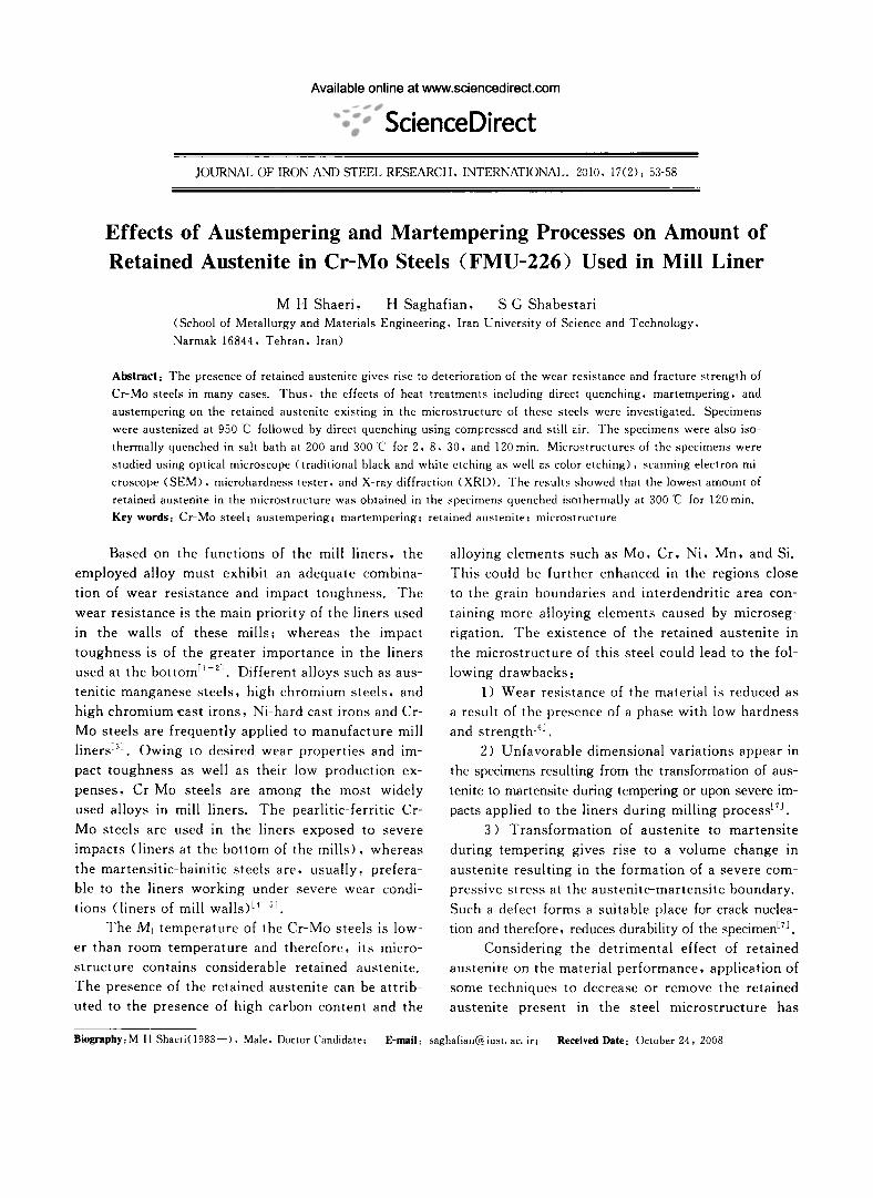
O. 78 O. 47 O. 95 2. 17 O.29 O. 2 0.015 0.008 Fig. 1 shows the microstructure of the speci
mens in the as-cast condition and as-quenched in the
compressed air, still air, and salt bath (at different
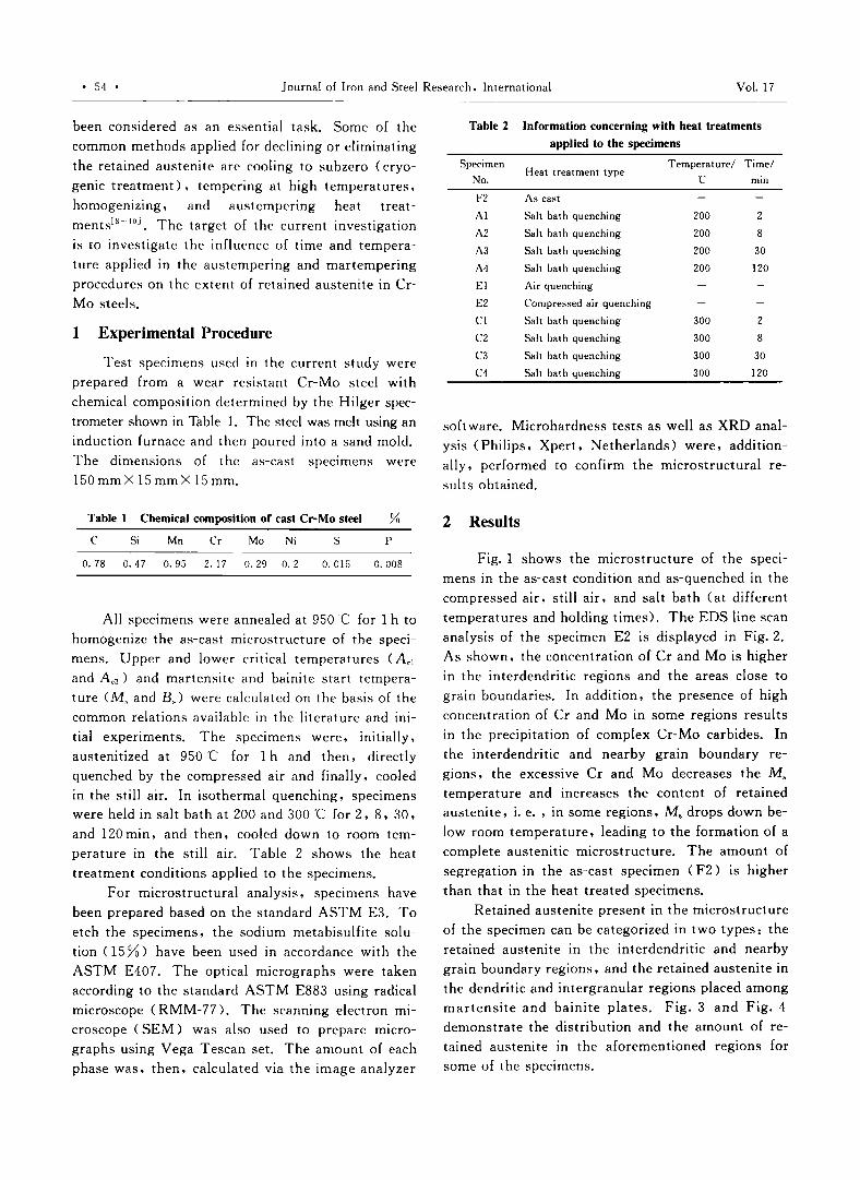
temperatures and holding times>' The £DS line scan
analysis of the specimen £2 is displayed in Fig. 2.As shown, the concentration of Cr and Mo is higher
in the interdendritic regions and the areas close to
grain boundaries. In addition, t he presence of high
concentration of Cr and Mo in some regions results
in the precipitation of complex Cr-Mo carbides. In
the interdendritic and nearby grain boundary re
gions, the excessive Cr and Mo decreases the M s
temperature and increases the content of retainedaustenite, i. e. , in some regions, Ms drops down be
low room temperature, leading to the formation of a
complete austenitic microstructure. The amount ofsegregation in the as-cast specimen (F2) is higher
than that in the heat treated specimens.
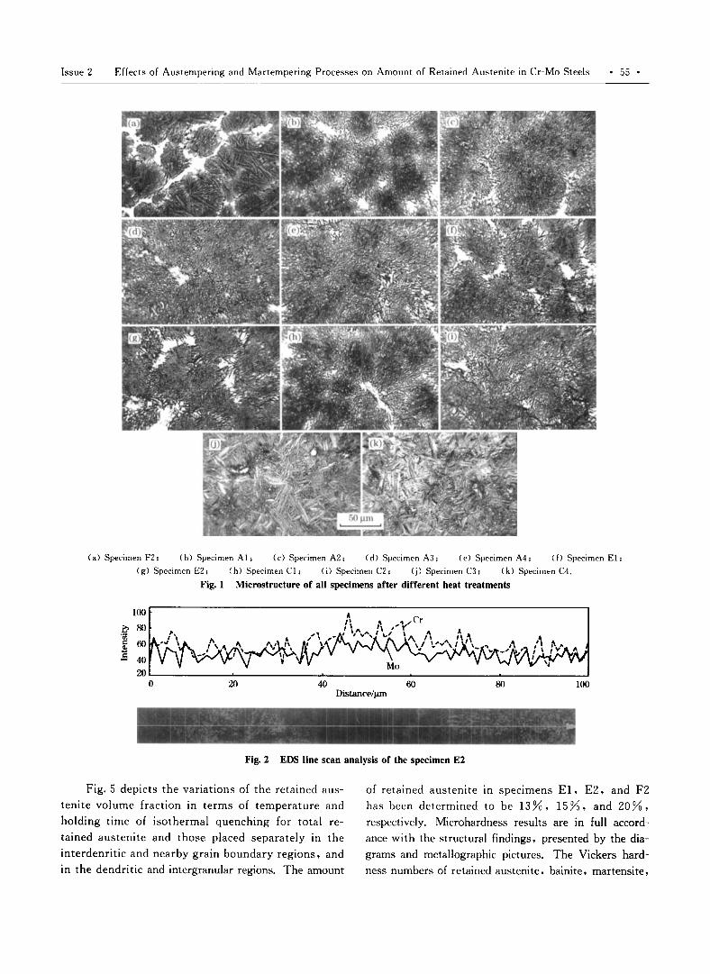
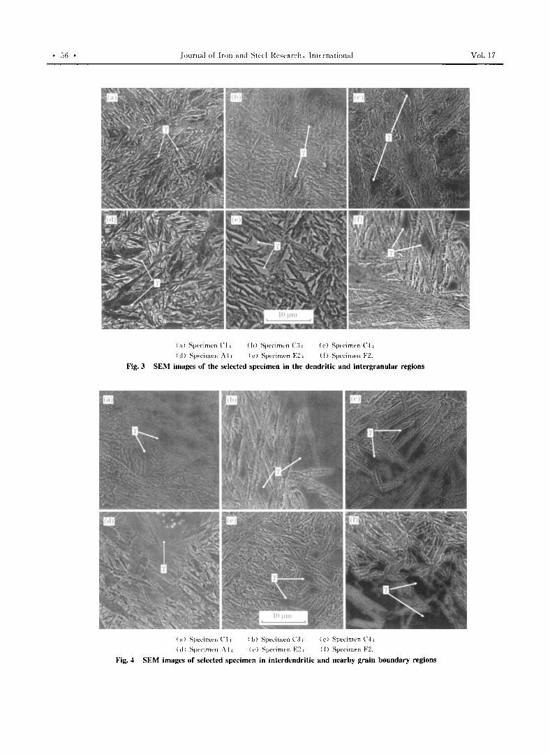
Retained austenite present in the microstructure
of the specimen can be categorized in two types: the
retained austenite in the interdendritic and nearbygrain boundary regions, and the retained austenite in
the dendritic and intergranular regions placed among
martensite and bainite plates. Fig. 3 and Fig. 4
demonstrate the distribution and the amount of re
tained austenite in the aforementioned regions for
some of the specimens.
Issue 2 Effects of Austempering and Martempering Processes on Amount of Retained Austenite in Cr-Mo Steels • 55 •
(a) Specimen F2, (b) Specimen AI, (c) Specimen A2, (d) Specimen A3, ( e) Specimen A4, (f) Specimen E1,
(g) Specimen E2; (h) Specimen Cl , (i) Specimen C2, (j) Specimen C3, Ck) Specimen C4.
Fig. 1 Microstructure of all specimens after different heat treatments
10080604020
100
080.~ 60~
.s 4020'-- -'- "-- ---"' ......... --'
oDistance/um
Fig. 2 EDS line scan analysis of the specimen E2
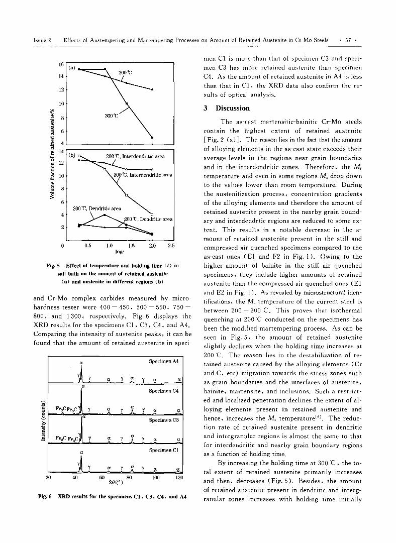
Fig. 5 depicts the variations of the retained aus
tenite volume fraction in terms of temperature and
holding time of isothermal quenching for total re
tained austenite and those placed separately in the
interdenritic and nearby grain boundary regions. and
in the dendritic and intergranular regions. The amount
of retained austenite In specimens E1. E2. and F2
has been determined to be 13%. 15%. and 20%.
respectively. Microhardness results are in full accord
ance with the structural findings. presented by the dia
grams and metallographic pictures. The Vickers hard
ness numbers of retained austenite. bainite. martensite.
• 56 • Journal of Iron and Steel Rl'~l'ar("h. lntvrnational
(,,) Sperinu-r: C 1; (h) Specimen C~: (c) Specimen C-l:
( d) Specimen .'\'1 ; (t') Specime-n F:2; (f) Specimen F2.
Fig. 3 SEM images of the selected specimen in the dendritic and intergranular regions
( ,,) Speci men C I ; ( h) Specimen C3; (c) Specimen ('4:
( d) Specirnen 1\1: ( (') Sperinu-n E2; (f) Specimen F2.
}'ig.4 SEM images of selected specimen in interdendritic and nearby grain boundary regions
Vol. 17
Issue 2 Effects of Austernpering and Martempering Processes on Amount of Retained Austenite in Cr- Mo Steels • 57 •
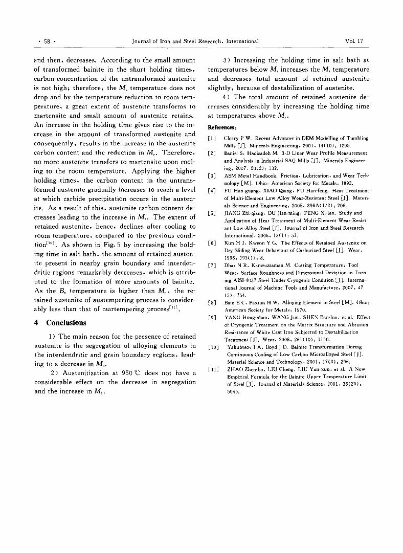
Fig. 6 XRD results for the specimens CI. C3. C4. and A4
Fig. 5 Effect of temperature and holding time (t) in
salt bath on the amount of retained austenite
(a) and austenite in different regions (b)
men Cl is more than that of specimen C3 and speci
men C3 has more retained austenite than specimen
C4. As the amount of retained austenite in A4 is less
than that in Cl , the XRD data also confirm the re
sults of optical analysis.
The as-cast martensitic-bainitic Cr-Mo steels
contain the highest extent of retained austenite
[Fig. 2 (a)]. The reason lies in the fact that the amount
of alloying elements in the as-cast state exceeds their
average levels in the regions near grain boundaries
and in the interdendritic zones. Therefore. the MEtemperature and even in some regions M, drop down
to the values lower than room temperature. During
the austenitization process. concentration gradients
of the alloying elements and therefore the amount of
retained austenite present in the nearby grain bound
ary and interdendrtic regions are reduced to some ex
tent. This results in a notable decrease in the a
mount of retained austenite present in the still and
compressed air quenched specimens compared to the
as-cast ones (El and F2 in Fig. 1 ). Owing to the
higher amount of bainite in the still air quenched
specimens. they include higher amounts of retained
austenite than the compressed air quenched ones (El
and E2 in Fig. 1). As revealed by microstructural iden
tifications. the M, temperature of the current steel is
between 200 - 300C. This proves that isothermal
quenching at 200C conducted on the specimens has
been the modified martempering process. As can be
seen in Fig. 5. the amount of retained austenite
slightly declines when the holding time increases at
200C. The reason lies in the destabilization of re
tained austenite caused by the alloying elements (Cr
and C. etc) migration towards the stress zones such
as grain boundaries and the interfaces of austenite.
bainite. martensite. and inclusions. Such a restrict
ed and localized penetration declines the extent of al
loying elements present in retained austenite and
hence. increases the M, temperature'". The reduc
tion rate of retained austenite present in dendritic
and intergranular regions is almost the same to that
for interdendritic and nearby grain boundary regions
as a function of holding time.
By increasing the holding time at 300 'C • the to
tal extent of retained austenite primarily increases
and then. decreases (Fig. 5). Besides. the amount
of retained austenite present in dendritic and interg
ranular zones increases with holding time initially
3 Discussion
1201008020/(°)
6040
16(a)
14
12
10
~ 8'2~
~ 6"0Q;
4c3ClJ 14... (b)....0
12c0',=<..;
10ol..::Q;
§ 8"0::>
6300 't, Dendritic area
4
~ti'~"2
0 0.5 1.0 1.5 2.0 2.5log/
ex Specimen A4
Y Y Y exex Y ex exex
Specimen C4
Fe"CFe"CY Y <; Y A Y ex exex
Specimen C3
YAFe"C Fe"C Y ?: Y Y ex ex
ex Specimen Cl
YY Xex Y Y ex ex
20
and Cr-Mo complex carbides measured by rmcro
hardness tester were 400 - 450. 500 - 550. 750
800. and 1 300. respectively. Fig. 6 displays the
XRD results for the specimens Ct , C3. C4. and A4.
Comparing the intensity of austenite peaks. it can be
found that the amount of retained austenite in speci-
• 58 • Journal of Iron and Steel Research. International Vol. 17
and then, decreases. According to the small amount
of transformed bainite in the short holding times,
carbon concentration of the untransformed austenite
is not high; therefore, the M. temperature does not
drop and by the temperature reduction to room tem
perature, a great extent of austenite transforms to
martensite and small amount of austenite retains.
An increase in the holding time gives rise to the in
crease in the amount of transformed austenite and
consequently, results in the increase in the austenite
carbon content and the reduction in M.. Therefore,
no more austenite transfers to martensite upon cool
ing to the room temperature. Applying the higher
holding times, the carbon content in the untrans
formed austenite gradually increases to reach a level
at which carbide precipitation occurs in the austen
ite. As a result of this, austenite carbon content de
creases leading to the increase in M.. The extent of
retained austenite, hence, declines after cooling to
room temperature, compared to the previous condition! 10]. As shown in Fig. 5 by increasing the hold
ing time in salt bath. the amount of retained austen
ite present in nearby grain boundary and interden
dritic regions remarkably decreases, which is attrib
uted to the formation of more amounts of bainite.
As the B. temperature is higher than M., the re
tained austenite of austempering process is consider
ably less than that of martempering process- "].
4 Conclusions
1) The main reason for the presence of retained
austenite is the segregation of alloying elements in
the interdendritic and grain boundary regions, lead
ing to a decrease in M..2) Austenitization at 950'C does not have a
considerable effect on the decrease in segregation
and the increase in M•.
3) Increasing the holding time in salt bath at
temperatures below M. increases the M. temperature
and decreases total amount of retained austenite
slightly, because of destabilization of austenite.
4) The total amount of retained austenite de
creases considerably by increasing the holding time
at temperatures above M •.
References I
[I] Cleary P W. Recent Advances in DEM Modelling of Tumbling
Mills [JJ. Minerals Engineering. 2001. 14( 10): 1295.
[2J Banisi S. Hadizadeh M. 3-D Liner Wear Profile Measurement
and Analysis in Industrial SAG Mills [JJ. Minerals Engineer
ing. 2007. 20(2): 132.
[3J ASM Metal Handbook. Friction. Lubrication. and Wear Tech
nology [MJ. Ohio: American Society for Metals. 1992.
[4J FU Han-guang , XIAO Qiang. FU Han-Ieng, Heat Treatment
of Multi-Element Low Alloy Wear-Resistant Steel [JJ. Materi
als Science and Engineering. 2005. 396AO/2): 206.
[5J JIANG Zhi-qiang , DU Jian-ming , FENG Xi-Ian. Study and
Application of Heat Treatment of Multi-Element Wear-Resist
ant Low-Alloy Steel [JJ. Journal of Iron and Steel Research
International. 2006. 130): 57.
[6J Kim H J. Kweon Y G. The Effects of Retained Austenite on
Dry Sliding Wear Behaviour of Carburized Steel [JJ. Wear.
1996. 1930): 8.
[7J Dhar N R. Kamruzzaman M. Cutting Temperature. Tool
Wear. Surface Roughness and Dimensional Deviation in Turn
ing AISI-4037 Steel Under Cryogenic Condition [JJ. Interna
tional Journal of Machine Tools and Manufacture. 2007. 47
(5): 754.
[8J Bain E C. Paxton H W. Alloying Element in Steel [M]. Ohio:
American Society for Metals. 1970.
[9J YANG Hong-shan. WANG Jun. SHEN Bao-luo , et al. Effect
of Cryogenic Treatment on the Matrix Structure and Abrasion
Resistance of White Cast Iron Subjected to Destabilization
Treatment [JJ. Wear. 2006. 261(0): 1150.
[10J Yakubtsov I A. Boyd J D. Bainite Transformation During
Continuous Cooling of Low Carbon Microalloyed Steel [JJ.Material Science and Technology. 2001. 17(3): 296.
[IIJ ZHAO Zhen-bo , LIU Cheng. LIU Yun-xun , et al. A New
Empirical Formula for the Bainite Upper Temperature Limit
of Steel [j]. Journal of Materials Science. 2001. 36(20):
5045.
Related Documents