A STUDY ON THE EFFECT OF AUSTEMPERING TEMPERATURE, TIME AND COPPER ADDITION ON THE MECHANICAL PROPERTIES OF AUSTEMPERED DUCTILE IRON A THESIS SUBMITTED IN PARTIAL FULFILMENT OF THE REQUIREMENT FOR THE DEGREE OF Master of Technology In Metallurgical and Materials Engineering Submitted By Sandeep Kumar Sahoo Roll No. 208 MM 102 Department of Metallurgical and Materials Engineering National Institute of Technology, Rourkela-769008 May 2012

Welcome message from author
This document is posted to help you gain knowledge. Please leave a comment to let me know what you think about it! Share it to your friends and learn new things together.
Transcript

A STUDY ON THE EFFECT OF AUSTEMPERING TEMPERATURE, TIME AND COPPER ADDITION ON
THE MECHANICAL PROPERTIES OF AUSTEMPERED DUCTILE IRON
A THESIS SUBMITTED
IN PARTIAL FULFILMENT OF THE REQUIREMENT FOR THE DEGREE OF
Master of Technology In
Metallurgical and Materials Engineering
Submitted By
Sandeep Kumar Sahoo Roll No. 208 MM 102
Department of Metallurgical and Materials Engineering National Institute of Technology, Rourkela-769008
May 2012

A STUDY ON THE EFFECT OF AUSTEMPERING TEMPERATURE, TIME AND COPPER ADDITION ON THE MECHANICAL PROPERTIES OF AUTEMPERED
DUCTILE IRON
A THESIS SUBMITTED
IN PARTIAL FULFILMENT OF THE REQUIREMENT FOR THE DEGREE OF
Master of Technology In
Metallurgical and Materials Engineering
Submitted By Sandeep Kumar Sahoo
Roll No. 208 MM 102
Under the guidance of
Prof. S. Sen Prof. S.C. Patnaik Dept. of Metallurgical & Materials Engg. Dept. of Metallurgical & Materials Engg.
NIT, Rourkela I.G.I.T, Sarang
DEPARTMENT OF METALLURGICAL & MATERIALS ENGINEERING NATIONAL INSTITUTE OF TECHNOLOGY, ROURKELA

NATIONAL INSTITUTE OF TECHNOLOGY, ROURKELA
CERTIFICATE
This is to certify that the thesis entitled “A Study on the Effect of
Austempering Temperature, Time and Copper Addition on the
Mechanical Properties of Austempered Ductile Iron ” submitted by Mr.
Sandeep Kumar Sahoo, Roll No. 208MM102 in partial fulfillment of the
requirements for the award of Master of Technology in Metallurgical and Materials
Engineering with specialization in “Metallurgical and Materials Engineering” at
National Institute of Technology, Rourkela (Deemed University) is an authentic
work carried out by him under our supervision and guidance. To the best of our
knowledge, the matter embedded in the thesis has not been submitted to any other
university/Institute for the award of any Degree.
Supervisor Co-Supervisor Prof. S. Sen Prof. S. C.Patnaik Met. & Mat. Engg. Head of the Deptt. National Institute of Technology, Met. & Mat. Engg. Rourkela-769008 I.G.I.T, Sarang, Dhenkanal-759146

Acknowledgement
I take this opportunity to express my deep regards and sincere gratitude to
my guide Prof. Sudipta Sen, Deptt. Met & Mat Engg., NIT, Rourkela for his
valuable guidance, untiring efforts and meticulous attention at all stages during my
course of work.
I would also like to convey my deep regards to my co-guide Dr. S. C.
Patnaik, Prof. & Head, Met & Mat Engg., I.G.I.T, Sarang for his patience,
constant motivation and regular monitoring of the work and inputs, for which this
work has come to fruition.
I express my gratitude to Prof. B. C. Ray, Head of the Department for
providing me the necessary facilities in the department.
I am thankful to Prof. B. B. Verma for his invaluable advice, constant help,
encouragement and inspiration.
I am also thankful to all the deptt. staff of both the institute for their co-
operation in experimental work.
Sandeep Kumar Sahoo

CONTENTS LIST OF FIGURES i
LIST OF TABLES iii
ABSTRACT iv
1. INTRODUCTION 1
2. LITERATURE REVIEW 2.1. Cast Iron 2 2.2. Ductile Cast Iron 4
2.2.1. Heat Treatment of Ductile Iron 6 2.2.1.1. Austenitizing the Ductile Cast Iron 7 2.2.1.2. Austempering of Ductile Cast Iron 8
2.3. Austempered Ductile Cast Iron (ADI) 11
2.3.1. Microstructure of ADI 14 2.3.2. Graphite in ADI 15 2.3.3. Copper in ADI 18 2.3.4. Properties of ADI compared to steel and cast iron 20 2.3.5. Applications of ADI 22
2.4. Aim of the work 25
3. EXPERIMENTAL PROCEDURE 3.1. Tensile Test 26 3.2. Hardness Test 28 3.3. Impact Test 28 3.4. Heat Treatment 30 3.5. Microstructure Study 31
4. RESULTS AND DISCUSSION
4.1. Mechanical Properties 4.1.1. Tensile Test 33 4.1.2. Hardness Test 38 4.1.3. Impact Test 40
4.2. Microstructural Observations 43
5. CONCLUSIONS 45
6. FUTURE WORK 46
REFERENCES 47

i
LIST OF FIGURES Figure 2.1 The graphite in different forms in the microstructure of cast iron
Figure 2.2 The austempering process
Figure 2.3 Time-Temp Curve of Bainite formation
Figure 2.4 Austempering Procedure
Figure 2.5 Isothermal transformation diagram of a processing sequence for austempering
Figure 2.6 The carbon content in bainitic α-phase vs. the transformation temperature
Figure 2.7 The tetragonality of bainitic α-phase lattice as a function of the transformation temperature
Figure 2.8 ADI Microstructure consisting of acicular ferrite in high carbon austenite matrix called Ausferrite
Figure 2.9 Different forms of graphite
Figure 2.10 Iron Carbon Diagram
Figure 2.11 Elongation vs. austempering time for a group of ductile iron alloys
Figure 2.12 Austempered microstructures etched in 2% nital
Figure 2.13 Tensile strengths and elongations in austempered ductile iron compared with other ductile irons.
Figure 3.1 Tensile specimen specifications
Figure 3.2 Dimensions for Charpy impact testing Figure 3.3 Arrangement for Charpy impact testing Figure 4.1 Effect of austempering time on tensile strength of Ductile Iron without Cu austempered at different temperatures
Figure 4.2 Effect of austempering time on Elongation of Ductile Iron without Cu austempered at different temperatures
Figure 4.3 Effect of austempering time on tensile strength of Ductile Iron with Cu austempered at different temperatures

ii
Figure 4.4 Effect of austempering time on Elongation of Ductile iron with Cu austempered at different temperatures
Figure 4.5 Effect of austempering time on Hardness of Ductile Iron without Cu austempered at different temperatures
Figure 4.6 Effect of austempering time on Hardness of Ductile Iron with Cu austempered at different temperatures
Figure 4.7 Effect of austempering time on Impact Toughness of Ductile Iron without Cu austempered at different temperatures
Figure 4.8 Effect of austempering time on Impact Toughness of Ductile Iron with Cu austempered at different temperatures
Figure 4.9 SEM microstructures of ADI austempered at 350°C for 1.5 hrs

iii
LIST OF TABLES Table 2.1 Partial list of castings produced in regular ductile iron
Table 2.2 List of castings produced in ADI
Table 3.1 Chemical composition of Ductile irons (Grade A)
Table 3.2 Chemical composition of Ductile irons (Grade B)
Table 3.3 The Austempering Window
Table 4.1 Tensile test results of as cast Ductile Iron samples
Table 4.2 Mechanical properties of austempered samples (without Cu)
Table 4.3 Mechanical properties of austempered samples (with Cu)
Table 4.4 Hardness of ADI without copper
Table 4.5 Hardness of ADI with copper
Table 4.6 Toughness values for ADI without Cu
Table 4.7 Toughness values for ADI with Cu

iv
Abstract The most rapidly growing area of cast technology is that of ADI or Austempered Ductile
Iron. ADI is a heat treated Ductile Iron or S.G. iron with a unique micro-structure: Ausferrite
which consists of high carbon Austenite and Bainitic ferrite with graphite nodules dispersed in it.
This unique microstructure yields excellent properties: high strength, toughness, good wear
resistance, good machinability and all that at low cost. The use of this type of cast iron as an
engineering material has been increasing day by day since its discovery. These properties can be
achieved upon adequate heat treatment which yields optimum microstructure for a given
chemical composition. But this type of treatment is bit tricky, since it requires controlled heating
and isothermal holding of the material.
In this work an investigation has been conducted on ductile iron with and without Copper
additions and austempered in a range of time and temperature. An attempt has been made to
study the effect of austempering time and temperature and the influence of copper addition on
the mechanical properties of ADI. The tensile strength was found to increase with decreasing
austempering temperature with maximum tensile strength seen in samples austempered at lower
temperatures, 250°C and shorter times. Maximum ductility was obtained after austempering for
1.5 hours. An increase in the ductility of ADI was found on copper addition. Hardness of both
the samples was found to be decreasing with increasing austempering time and temperature, and
toughness of ADI was seen to be increasing with increasing time and temperature and was more
prominent in case of ADI samples with copper.
Key words: ADI, austempering, ausferrite, elongation, toughness

Introduction

1
1. Introduction The material which offers the design engineer the best combination of low cost, design
flexibility, good machinability, high strength to weight ratio & good toughness, wear resistance
is Austempered Ductile Iron (ADI) [1]. Austempered Ductile Irons are an interesting class of
materials because of their unique microstructure and interesting properties. When subjected to
austempering treatment ductile iron transforms to a microstructure consisting of ferrite and
stabilized austenite rather than ferrite and carbide as in austempered steels. Because of the
presence of stabilized austenite, ADI exhibits excellent combination of strength and ductility,
together with good fatigue and wear properties [2,3]. Compared to the conventional grades of
Ductile Iron, ADI delivers twice the strength for a given level of ductility in the form of
elongation. But achieving excellent mechanical properties of the ADI material is not an easy task
as they depend on austempered microstructure which is a function of its processing window. The
optimum combination of high carbon austenite and bainitic ferrite of ADI makes it possible to
compete against steel forgings and other engineering alloys in terms of mechanical properties,
physical properties, weight saving and all that at low cost. ADI offers superior combination of
properties because it can be cast like any other member of the Ductile Iron family, thus offering
all the production advantages of a conventional Ductile Iron casting. The ductile Iron casting is
subsequently subjected to the austempering process to produce mechanical properties that are
superior to conventional ductile iron and forged steel. Due to its vast area of applications,
extensive works are being carried out now-a-days to study the processing and characterization of
this material.

Literature Review
Cast Iron
Ductile Cast Iron
o Heat Treatment of Ductile Iron
Austenitizing the Ductile Cast Iron
Austempering of Ductile Cast Iron
Austempered Ductile Cast Iron (ADI)
o Microstructure of ADI
o Graphite in ADI
o Copper in ADI
o Properties of ADI compared to steel and cast iron
o Applications of ADI
Aim of the work

2
2. Literature Review 2.1. Cast Iron
ADI stands for Austempered Ductile Iron and comes under the cast iron family. Cast iron
is the eutectiferrous Iron-Carbon alloy i.e. eutectic reaction takes place during its solidification.
As the liquidus line of iron-carbon diagram moves downward till the eutectic composition
melting of cast iron becomes easier. The ductility of cast iron is very low. These alloys cannot be
mechanically worked at room temperature. Most of the cast irons are not malleable at any
temperature. However, they melt readily and they can be cast into complicated shapes. Then they
are usually machined to final dimensions. Since casting is the only suitable process for shaping
these alloys therefore they are called cast irons. Plain Iron carbon alloys with carbon up to 2.11
wt % in iron are called steels and beyond that the alloys are called cast irons. The cast irons are
brittle. Theoretically the carbon content of cast iron can lie in between 2.11 % to 6.67 %. As
higher carbon contents tend to make the cast iron more brittle, the industrial cast irons have
carbon normally in the range of 2.11% to 4.0% [2, 4].
Cast iron is very similar in structure and composition to blast furnace pig iron, except that
pig iron contains mechanically held slag and large amount of gases. The pig iron finds
application to cast mould for steel-ingot, and therefore is called cast iron. Cast irons are
essentially re melted pig iron, the composition of which has undergone some adjustments during
melting process, by mixing it with cast iron scrap, steel-scrap etc. The melting unit may be
cupola, electric arc or induction furnace etc.
The term “Cast iron” refers not to a single material, but to a family of materials whose
major constituent is iron with important amount of carbon and silicon. Cast irons are natural
composite materials whose properties are determined by their microstructures- the stable and
meta-stable phases formed during solidification or subsequent heat treatment [5]. The best
method to classify cast iron is the metallographic structure. The several variables which lead to
the different types of cast irons are as given under.
• Carbon content

3
• Alloying element
• Impurity content
• Cooling rate during and after freezing
• Heat treatment after casting
These variables influence the form and shape of the carbon. Carbon in cast iron can be present in
two forms:
• Combined form (Metastable)- cementite (Fe3C) as in white cast iron
• Free form (stable)- graphite as in gray cast iron
As cementite is very brittle it makes white cast iron brittle and finds limited applications
where only wear resistance is of importance. But graphite is soft; again if in spheroidal form as
in case of ductile iron it increases the mechanical properties. But formation of graphite in cast
iron is not spontaneous as that of Fe3C metastable phase. Kinetically it is easier to produce Fe3C
(6.67 wt %C) rather than graphite (100 wt %C). So it is needed to adjust the processing window
and use of graphitisers like Si, Ni and spherodisers like Mg, Ce for the formation of spheroidal
graphite in cast iron [4].
The shape and distribution of the graphite will greatly influence the physical and
mechanical properties of the cast iron. Based on the shape and form of the carbon in the cast iron
and alloying additions the different types of cast irons are as follows:
• White cast iron
• Malleable cast iron
• Gray cast iron
• Ductile cast iron
• Alloy cast iron
Although the common cast irons are brittle and have lower strength than steels yet they
are cheap and can be cast more readily. The cast irons also have other useful properties. Further,
by proper alloying, good foundry control, and through appropriate heat treatment, the properties
of cast iron may be varied over a wide range. Significant developments in foundry control have
led to the production of huge tonnage of cast iron with consistent properties [5].

4
2.2. Ductile Cast Iron
Nodular Iron or Spherodised Graphite (SG) iron is known as Ductile Iron which was
patented in 1948. After a decade of intensive development work, in the 1950’s, ductile iron had a
phenomenal increase in the use as an engineering material during the 1960’s, and the rapid
increase in commercial application continues today [4].
SG iron derives its name as it has graphite in the form of spheroid embedded in the steel
matrix, normally of ferrite, or pearlite. And in the as-cast form, it exhibits measurable ductility.
By contrast, neither white cast iron nor grey cast iron exhibits significant ductility. Nodular cast
iron differs from malleable iron in the way that it is usually obtained as a result of solidification
and not through heat treatment in the solid state. The spheroids in nodular iron are more rounded
than the irregular temper carbon aggregates found in malleable cast iron.
The total carbon content of nodular cast iron is the same as in gray cast iron. Spheroidal
graphite particles form during solidification due to the presence of small amount of certain
alloying element. These nodules are produced by treating the molten alloy with magnesium, or
cerium or a combination of two elements such as Ca, Ba, Li, and Zr causing spheroidal graphite
to grow during solidification. Since these elements have a strong affinity for sulfur, the base iron
alloy sulfur content must be below 0.015% for treatment to be effective. Ductile iron having a
maximum of 10% pearlite in the as cast matrix is known as ferrite iron. This structure gives the
maximum ductility, toughness and machinability.
A matrix structure which is largely pearlite can be produced as cast or by normalizing.
Normalizing is carried out by air cooling from temperature of 870 to 900oC. Pearlite ductile irons
are stronger but less ductile than ferrite iron. A martensite matrix may be obtained by quenching
in oil or water from 870 to 927oC. The quenched structures are usually tempered after hardening
to the desired strength and hardness level.
Austenite ductile iron is highly alloy type which retains their austenitic structure down to
at least -60°C. These irons are used because of its high corrosion resistance and good creep
properties at elevated temperature.

5
It was found that by adding magnesium to the melt before pouring caused the graphite to
form nodules rather than flakes. This produced a new material with excellent tensile strength and
ductility. With the addition of the mechanical properties of this material with the advantages
already offered by cast iron led to it finding its way into almost every major area of engineering,
and in many cases replacing existing steel castings or forgings due to achievable cost savings.
The matrix of ductile irons can be varied from a ferritic structure which is soft and
ductile, through pearlitic structures which are harder and higher strength to a very hard, higher
strength and comparatively tough tempered martensitic or bainitic structure. Thus, a wide range
of combinations of strength and ductility can be achieved. The general grades of ductile iron
commonly have ferritic, ferritic and pearlitic, or pearlitic structures.
The different grades are produced by controlling the matrix structure around the graphite
either the as cast or by subsequent heat treatment processes. Only minor compositional
differences exist among the regular grades, and these adjustments are made to promote the
desired matrix microstructures which ultimately enhance their properties. Alloy addition may be
made to help in controlling the matrix structure as-cast to provide response to heat treatment.
Experiments have shown that proper heat treatment methods can improve the properties
of Cast Iron. And in some cases it may even overshadow the advantages of steel over Cast Iron.
A large number of researchers are working on austempered Cast Iron which shows very good
combination of properties.
(a) Flakes in Gray Cast Iron (b) Spheroids in SG Iron
Figure 2.1 The graphite in different forms in the microstructure of cast iron

6
2.2.1. Heat Treatment of Ductile Iron
Nodular cast irons are primarily heat treated to create matrix microstructures and
associated mechanical properties not readily obtained in the as-cast condition. As-cast matrix
microstructures usually consist of ferrite or pearlite or combinations of both, depending on cast
size and composition. The normalizing, hardening, and austempering heat treatment, involve
austenitization, followed by controlled cooling or isothermal reaction, or a combination of the
two. The heat-treatments can produce a variety of microstructures and greatly improve the
mechanical properties of ductile cast iron. These microstructures can be separated into two broad
classes:
• Those in which the matrix phase is the thermodynamically stable body-centered cubic,
ferrite structure
• Those with a matrix phase that is a meta-stable face-centered cubic, austenite structure.
The former are usually generated by the annealing, normalizing and tempering, or
quenching and tempering processes.
The latter are generated by austempering, an isothermal reaction process resulting in a
product called austempered ductile iron (ADI).
Figure: 2.2: The austempering process [1]

7
Other heat treatments in common industrial practice include stress-relief annealing and
selective surface heat treatment. Stress-relief annealing does not involve major micro-structural
transformations. And selective surface treatment processes like flame and induction surface
hardening involve micro-structural transformations but only in selectively controlled parts of the
casting [6].
2.2.1.1. Austenitizing the Ductile Cast Iron
The objective of austenitizing is to produce an austenitic matrix with as uniform carbon
content as possible prior to thermal processing. For a typical ductile cast iron, it must be heated
above the upper critical temperature so that the austenitizing temperature is in two-phase
(austenite and graphite) region. This temperature varies with alloy content. The austenite carbon
content in equilibrium with graphite increases with an increase in austenitizing temperature. This
ability to select (within limits) the carbon content of the austenite matrix makes austenitizing
temperature control important in processes that depend on carbon in the matrix to drive a
reaction. The hardenability or austemperability of Ductile Iron depends to a significant degree on
matrix carbon content. The composition, the original microstructure, and the section size of the
Ductile Iron determine the time required for austenitizing.
A typical Iron-Carbon diagram with 2% Si content shows as austenitizing temperature
increases, so does the matrix carbon content. The matrix carbon content also depends on type
and amount of alloying element present and their location in the matrix. The most important
determinant of matrix carbon content in ductile irons is the silicon content. As Silicon content in
ductile iron increases for a given austenitizing temperature, the carbon content in the matrix
decreases [7].
2.2.1.2. Austempering of Ductile Cast Iron
For optimum strength and ductility of Ductile cast Iron an austempered structure of
austenite and ferrite may be produced. The austempered matrix is responsible for a significantly
better tensile strength along with good ductility than is possible with any other grade of ductile

8
cast iron. To obtain these desirable properties a careful attention to section size and the time-
temperature exposure during austenitizing and austempering is required [7].
Figure 2.3 Time-Temp Curve of Bainite formation
The Austempering process consists of the following steps.
• Heating the Ductile Iron castings to austenitizing temperature.
• Holding at austenitizing temperature to dissolve carbon in austenite.
• Quenching quickly to austempering temperature to avoid pearlite formation.
• Holding at austempering temperature in molten salt bath for isothermal transformation to
ausferrite.
• Air cooling to room temperature

9
Figure 2.4 Austempering Procedure [8]
• The austenitizing times and temperatures (842° to 927° C) are controlled to ensure
formation of fine grained austenite and uniform carbon content in the matrix. The precise
temperature is grade dependant.
• Quench time must be controlled within a few seconds, to avoid formation of pearlite
around the carbon nodules, which would reduce mechanical properties. Quench
temperatures (235° to 400° C.) must be above the Ms temperature.
• In the austempering step which follows austenitizing, the temperature of the salt bath
must also be closely controlled. The austempering time must also be controlled, to avoid
over- or under-processing. By the end of this step, the desired ADI ausferrite structure
has developed.

10
Figure 2.5 Isothermal transformation diagram of a processing sequence for austempering [7].
The isothermal transformation diagram for a ductile cast iron, together with a processing
sequence depicting the production of ADI is shown in figure 2.5. In this process, austenitizing is
followed by rapid quenching, usually in molten salt, to the bainitic temperature range for a time
that allows the unique metastable carbon rich (~2%C) austenitic matrix (γH) to evolve
simultaneously with nucleation and growth of plate like ferrite (α) or ferrite plus carbide,
depending on the austempering temperature and time. This austempering reaction progresses to a
point at which the entire matrix has been transformed to the metastable product of carbon rich

11
(~2%C) austenitic matrix (γH) with bainitic ferrite (stage-I in figure 2.5), and then the product is
frozen by cooling to room temperature before the true bainitic ferrite plus carbide phase can
appear (stage-II in figure 2.5). In ductile cast irons, the presence of 2-3% Si prevents the rapid
formation of iron carbide (Fe3C). Hence the carbon rejected during ferrite formation in first stage
of the reaction retains in the austenite matrix, enriching it and stabilizing it thermally to prevent
martensite formation upon subsequent cooling. The processing sequence in figure 2.5 shows that
the austempering reaction is terminated before stage-II begins and it illustrates the decrease in
the Martensitic start (Ms) and Martensitic finish (Mf) temperatures as γH forms in stage-I. Care
should be taken to avoid formation of undesirable bainite as unlike steel, bainite in cast iron
microstructures exhibits lower toughness and ductility [7].
2.3. Austempered Ductile Cast Iron (ADI)
ADI, the most recent addition to the Ductile Iron family, is a sub-group of Ductile Irons
produced by giving conventional Ductile Iron a special austempering heat treatment. An
optimum combination of high carbon austenite and bainitic ferrite (ausferrite) confers excellent
mechanical properties to such cast irons on heat treatment making it possible to produce a family
of ADIs. This in turn allows a wide range of applications with ADI competing favorably against
steel forgings in terms of mechanical properties, manufacturing cost, physical properties and
weight saving.
ADI is nearly twice as strong as pearlitic Ductile Iron and it still retains high elongation
and toughness. This combination provides a material with superior wear resistance and fatigue
strength. Ductile iron castings are freely machinable before heat treatment. The casting
properties are upgraded after machining through austempering treatment.
The bainitic transformation starts at the interfaces with the nucleation and growth of
individual platelets of bainitic α-phase. The transformation progresses as a result of the
formation of new individual platelets within clusters, which are called sheaves. These individual
platelets are named ‘sub units’ or a sheaf. All subunits within a sheaf have the same
crystallographic orientation. It is thought that sub units grow without diffusion, but the excess of
carbon is quickly partitioned into the untransformed austenite [11].

12
It has been reported that two austenites with different carbon contents were found in the
austempered ductile iron (ADI) matrix structure, but it is not clear how the change of carbon
contents in both austenites affect the reaction [12]. The work of Kustuv and Taran [11] on ductile
iron has shown that the volume fraction of austenite in the matrix in the isothermal
transformation range between 400-250°C decreases (from 33 to 18%) with decrease of
transformation temperature. The variation of carbon content and the c/a ratio in the bainitic α-
phase against transformation temperature are given in figures 2.6 and 2.7 respectively.
Figure 2.6 The carbon content in bainitic α-phase vs. the transformation temperature [11]
It is clear from figure 2.6 that the decrease of isothermal temperature within an interval of
500-250°C leads to a higher carbon amount trapped in the bainitic α-phase at the termination of
isothermal transformation.

13
Figure 2.7 The tetragonality of bainitic α-phase lattice as a function of the transformation
temperature [11]
The tetragonality (c/a ratio) in the bainitic α-phase is found to decrease with increasing
temperature.
Different alloying elements have their individual effect and combinations of these
alloying elements are selected for their effect on different properties of ADI like hardenability,
elongation, toughness, tensile strength, hardness etc. by stabilizing different phases and
transformation behavior. Table 2.1 summarizes the effects of various alloying elements on the
austempering behavior of ADI.
Table 2.1 Effects of various alloying elements on the austempering behavior of
austempered ductile iron ADI [7].
Element Alloying effects
Carbon Increasing in the range 3-4% increases the tensile strength but has negligible
effect on elongation and hardness. Carbon should be controlled within the range
3.6-3.8%.

14
Silicon Silicon in ADI promotes graphite formation, decreases the solubility of carbon in
austenite, increases the eutectoid temperature and inhibits the formation of
bainitic carbide. Increasing the silicon content increases the impact strength of
ADI and lowers the ductile-brittle transition temperature. Silicon should be
within the range 2.4-2.8%.
Manganese Manganese can be both a beneficial and harmful element. It strongly increases
hardenability, but during solidification it segregates to cell boundaries where it
forms carbide and retards the austempering reaction. To improve properties and
reduce the sensitivity of ADI to section size and nodule count, it is advisable to
restrict the manganese level in ADI to less than 0.3%.
Copper Up to 0.8% Cu may be added to ADI to increase hardenability. Copper has no
significant effect on tensile properties but increases ductility at austempering
temperatures below 350°C.
Nickel Up to 2% Ni may be used to increase the hardenability of ADI. For austempering
temperatures below 350°C nickel reduces tensile strength slightly but increases
ductility and fracture toughness.
Molybdenum Molybdenum is the most potent hardenability agent in ADI and may be required
in heavy-section castings to prevent the formation of pearlite. However, both
tensile strength and ductility decreases as the molybdenum content is increased
beyond that required for hardenability. The level of molybdenum should be
restricted to not more than 0.2% in heavy-section castings.
2.3.1. Microstructure of ADI
ADI is a heat treated Ductile Iron with a unique micro-structure consisting of Ausferrite
which consists of high carbon Austenite and Bainitic ferrite with graphite nodules dispersed in it.
ADI is a ductile iron that has been heat treated by the austempering process to make it tougher
than regular ductile iron of half the strength. ADI is comparable in strength to heat treated
wrought steels, has exceptional wear and fatigue resistance and has the ability to be work
hardened. As the carbon rich austenite phase is stable in Austempered Ductile Iron it enhances
15
the bulk properties. Furthermore, while the austenite is thermodynamically stable, it can undergo
a strain-induced transformation when locally stressed, producing islands of hard martensite that
enhance wear properties. This behaviour contrasts with that of the metastable austenite retained
in steels, which can transform to brittle martensite [9].
Figure 2.8 ADI Microstructure consists of acicular ferrite in high carbon austenite matrix called
Ausferrite [10]
2.3.2. Graphite in ADI
Graphite is the stable form of pure carbon in cast iron. Its important physical properties
are low density, low hardness and high thermal conductivity and lubricity. Graphite shape, which
can range from flake to spherical, plays a significant role in determining the mechanical
properties of cast irons. The compact spheroid interrupts the continuity of matrix much less than
graphite flake and this results in higher strength and toughness compared with a similar structure
of gray cast iron. Figures 2.9 (a) and (b) show that graphite flakes act like cracks in the iron
matrix, while graphite spheroids act like “crack arresters", giving the respective irons
dramatically different mechanical properties [5].

16
(a) (b)
Figure 2.9 Different forms of graphite
In iron-carbon alloys, though graphite is more stable phase than cementite but kinetically,
it is easier to produce cementite than graphite. When graphite forms directly from the liquid, it is
called primary graphitization, but when the graphite forms from the dissociation of cementite, it
is called second stage graphitization. The formation of graphite from liquid takes place in a
narrow range of temperature interval (1153-1147°C for plain carbon) and also the formation of
graphite from austenite (738-727°C) i.e. under the condition of small under cooling. This
requires the alloy to be cooled slowly.
Nucleation of graphite requires much more energy and large amount of diffusion of
carbon to the nuclei and iron atoms away from it to get 100% carbon to segregate. So formation
of graphite from liquid in pure iron-carbon alloy is almost a rare reaction, unless the factors for
graphite formation are favorable. Commercial cast iron melt always contains fine particles of
inclusion, even particles of graphite. Nucleation of graphite on some of these inclusions needs
less energy than that required or nucleation of cementite and thus graphite crystal can be formed
kinetically even at temperatures below 1147oC.

17
Figure 2.10 Iron Carbon Diagram
Graphite thus can form not only from liquid or austenite (738-727°C), the metastable
cementite under favorable conditions, such as high temperatures can decompose to austenite +
graphite (above738°C) or ferrite + graphite (below 738°C). The former is a faster process, but
complete graphitization does not occur as 0.68% C remains dissolved in austenite, whereas the
latter is the slower process, but complete graphitization occurs.

18
2.3.3. Copper in ADI
Figure 2.11 Elongation vs. austempering time for a group of ductile iron alloys [7]
Nickel and Copper segregate to graphite nodule sites and do not form detrimental
carbides [7]. According to the experimental work of P. W. Shelton, A. A. Bonner [13] and
Olivera Eric [14] alloying with copper increases elongation and impact energy but decreases the
strength of ADI. According to their results it was seen that a straight forward addition of copper
to a conventionally produced and heat treated ADI had not produced the well defined copper
coated graphite nodules those were hoped for. In some cases the copper was associated with
graphite nodules, but not as a thin film. There were also isolated pools of copper present in the
microstructure comparable in size with graphite. The distribution and size of graphite spheroids
was similar however for both the materials, with no evidence that the copper addition influenced
either. Where there was porosity, a concave graphite surface or irregularity in the shape of the
graphite nodule, the copper was often attracted to those features.

19
Figure 2.12 Austempered microstructures, etched in 2% nital. (a) Plain ADI austenitised at
940°C and austempered at 320°C. (b) Copper enriched ADI austenitised at 900°C and
austempered at 290°C, showing nodules with copper-rich phase around all, or part of graphite
nodule. (c) Copper enriched ADI austenitised at 940°C and austempered at 320°C showing a
discrete copper globule, left of centre [14].

20
2.3.4. Properties of ADI compared to steel and cast iron
ADI is a proven cost-effective alternative to cast and forged steel and other members of its
family as it offers the following advantages:
Tensile Strength and Yield Strength of ADI are at least twice those of standard ductile
irons.
Fatigue Strength of ADI is typically 50% higher than that of standard ductile irons. It can
be further increased by shot peening or fillet rolling. The lower hardness grades of ADI
are suitable for structural applications [15].
The excellent impact and fracture-toughness properties of ADI make it ideal for
applications such as ground-engaging tools.
ADI weighs only 2.4 times more than aluminum and is 2.3 times stiffer. ADI is also 10%
less dense than steel. Therefore, the relative weight per unit of yield strength of ADI
when compared with that of various aluminums and steels, it is easy to see the
engineering and design advantages inherent in ADI [15].
The higher hardness grades of ADI have excellent wear characteristics. Unlike case-
hardened materials, typically the ADI is uniformly hardened throughout the part. Also,
ADI work-hardens when stressed. This produces a thin surface of very hard martensite
where wear resistance is most needed.
ADI is usually 15% to 20% less costly than steel forgings or castings. It is the most
economical way of obtaining tensile, yield, or fatigue strength. ADI often competes
favorably with heat-treated and alloy steels for heavy-duty applications where reliability
is crucial. It is a useful upgrade from standard grades of ductile iron. In some cases it
replaces manganese steel and nickel-chrome iron. Because of ADI's high strength-to-

21
weight ratio, it has even replaced aluminum where the design allows reduced section
sizes
Nearness to net shape reduces machining costs.
Tooling is less expensive with improved lead time when compared to forging dies.
The amount of energy required to produce A.D.I. can be up to 50% less than steel casting
and forging counterparts [15,16,17].
Figure 2.13 Tensile strengths and elongations in austempered ductile iron compared with other ductile irons [1].

22
2.3.5 Applications of ADI
Engineering applications of cast iron have been traditionally based upon gray (Flake
graphite) irons providing a range of tensile strengths between about 150 N/mm2 and 400 N/mm2
with recommended design stresses in tensile applications of 0.25 x tensile strength. Despite their
limited strength gray irons provided very useful combinations of properties, which have ensured
there wide continuing use. In fact gray irons still account for nearly 70 % of all iron castings
produced. In contrast ductile irons have tensile strengths ranging from 350 to 1500 N/mm2 with
good elongation and high toughness. They now account for about 25 % of iron casting
production serving in safety critical applications where they have replaced steel casting, forging
and fabrications with technical and cost advantage.
The main difference between ductile iron and gray iron is the morphology of graphite
particles which take on a nodular or almost spherical form after suitable treatments are made to
the melt. The major micro structural constituents of ductile iron are: the chemical and
morphological forms taken by carbon, and the continuous metal matrix in which the carbon
and/or carbides are dispersed.
All of the advantages of Ductile Iron, described have contributed to the growth of this
engineering material. The primary material that has been replaced is steel, in the form of
castings, forgings and fabrications. However, Ductile Iron parts have also replaced gray iron,
malleable iron and aluminium castings as well, proving that Ductile Iron is very cost effective.

23
Table 2.2 Partial list of castings produced in regular ductile iron [20]
(Casting weights from 10 grams to over 170 tons) Automotive and Agricultural
Axle housings Body bolsters Brake calipers Brake cylinder Camshafts Clutch drums Clutch plates Connecting rods Crankshafts Cultivator parts Cylinder bushings Differential carrier Differential case Exhaust manifolds Front wheel forks Gears & pinions
Hitch brackets Hubs Motorcycle components Pinion
Pinion flange Planet carrier Piston rings Plow shares Rocker arm Ring gears Spindles Wheels
Steering housings Tire molds Truck cab mount Steering knuckles
Yokes
Other Transportation and Construction
Anchors Axle housings Backhoe arms Back. stabilizers Bridge bearings Cable coupler Car journal boxes Charge buckets Chute plates Conveyor frames Covers Crawler sprockets Elevator buckets Hand tools Hoist drums Idlers Manhole covers Mill heads Pipe flanges Propellers Pole line hardware Railroad wheels Rollers Runway grates Swing pivots Track crossovers Tree grates
General Engineering
Actuating cams Armature spiders Barstock Bearing housings Die blocks Boiler segments Bolts Brackets Furnace grates Cams Clamp cylinders Commutator drums Bell cranks Compressor bodies Crusher hammers Damper frames Briquetting rams Dredge sprockets Forging dies Frames and jigs Crankcases Gyratory crushers Ingot molds Heater coils Hinges Hydraulic valves Insulator caps Lawn mower parts Lightening arresters Machine frames Mandrels Meter components Nuclear fuel container Nuts Oil manifolds Overhead switch gear Pile driver heads Pipe forming dies Pipe fittings Pistons Pressure pipe Press roll bodies Pump bodies Ratchets Resistance grids Rocker brackets Rolling mill rolls Rope clamps Rotors Rubber molds Sawmill beds Scaffold fittings Shafts Shear frames Spindles Suspension brackets Tank covers Thread guides Tunnel segments Turbine casing Turret heads Valves Vise frames Wheels
Worm gears Wood augers

24
Austempered Ductile Iron is increasingly the material of choice as designers and
engineers seek cost effective performance from their components and systems. In particular,
manufacturers engaged in moving parts and safety critical items have benefited from increased
strength, greater wear resistance, noise reduction and weight saving. [18,19].
ADI is now established in many major markets: Table 2.3 List of castings produced in ADI [20]
Agricultural Equipment
Digger points Fertilizer knives Corn grinder plates Planter rachet gear Pump cams Slip clutch parts Pump rotor Track shoes Tow hooks Snow plow shoe Link arm Eye bolts Jacking stand gear Sprockets Wear plates Hitches Sickle guards Wheel hubs Pavement breakers Wear guides Rollers Steering shafts Control arms Plow & till points
Automotive and Truck
Crankshafts Connecting rods Control arms Engine mount Diesel piston head CV joints Truck hub Tripot housing Timing gears Ring & pinion gears Steering knuckles Camshafts Differential housing Wheel spindle Rocker arms Shackle brackets Steering housing Tie rods Suspension arms Drive yokes Brake components U-bolt stop plates I-beams
Railroad
Track plate Brake caliper Top caps Mine car wheels Axle holder Wear shoes Spring holder Wheels Shock absorbers Brake blocks Shoes Engine parts
Machinery and Material Handling
Power trans. gears Conveyor link Pump components Conveyor link holder
Bearing block Crankshafts Chain sprockets Conveyor chains Cams Wedges Jackhammer
housing Mining wear parts
Wear pads Pole line hardware Sprockets Dies Rollers & Guides Bull gears Bevel gears Grates Spur gears Military Armor Projectiles Track shoes Rocket bodies Track guides Engine rotors Struts Suspension

25
2.4. Aim of the work
From the literature review it is seen that austempered ductile iron as an engineering
material has found increasing applications over the years since its discovery because of its
excellent mechanical properties such as high strength, toughness, good wear resistance, good
machinability and all that at low cost. The excellent mechanical properties of ADI material are
due to its unique microstructure of ausferrite which consists of high carbon austenite and
bainitic ferrite with graphite nodules dispersed in it. The austempered microstructure is a
function of the austempering time and temperature and therefore achieving excellent mechanical
properties depends on selection and control of proper austempering time, temperature and
alloying additions.
Therefore, an attempt has been made in the present work to study the effect of
austempering temperature, time and copper addition on the mechanical properties of
austempered ductile iron such as tensile strength, % elongation, hardness and impact toughness
by carrying out austempering treatment of ductile iron at 350°C, 300°C, and 250°C for 0.5hr,
1hr, 1.5hrs and 2hrs.

Experimental Procedure
Tensile Test
Hardness Test
Impact Test
Heat Treatment
Microstructure Study

26
3. Experimental Procedure For this work two types of ductile irons: one containing copper about 0.5 wt% (Grade A)
and the other without copper (Grade B), were collected from L & T, Kansbahal, Rourkela. The
detailed chemical compositions of these materials are as per the table 3.1 and table 3.2.
Table 3.1 Chemical composition of Ductile irons (Grade A)
Table 3.2 Chemical composition of Ductile irons (Grade B)
Elements C Si Mn S P Cr Ni Mo Cu Mg % 3.53 2.11 0.19 0.013 0.033 0.02 0.45 0.001 0.01 0.043
3.1 Tensile Test
The specimens were prepared from the procured samples by carrying out machining
operations such as grinding, turning and milling. This was done to obtain the required dimension
(grip dia=20mm, gauge dia=14mm, gauge length=70mm, grip length=50 mm) for 100 tonne
UTM testing.
Elements C Si Mn S P Cr Ni Mo Cu Mg % 3.54 2.33 0.24 0.013 0.030 0.02 0.14 0.001 0.51 0.044

27
20mm
50mm
14mm
70mm
Section to be machined for hardness testing
Figure 3.1 Tensile specimen specifications
The tensile test was carried out before and after the heat treatment

28
3.2. Hardness Test
The samples were taken for Brinell hardness test. The testing machine consists of a 10mm diameter steel ball indenter. A load of 3000 kgf was applied for 15 sec. The Brinell hardness number (BHN) is expressed as BHN =
Where, P = load applied (kgf)
D = Dia of the ball (mm) d = Dia of indentation (mm)
3.3. Impact Test
The Charpy impact test, also known as the Charpy v-notch test, is a standardized high
strain-rate test which determines the amount of energy absorbed by a material during fracture.
This absorbed energy is a measure of a given material's toughness and acts as a tool to study
temperature-dependent ductile-brittle transition. According to ASTM A370, EN 10045-1 and
ISO 148 the standard specimen size for Charpy impact testing is 10mm×10mm×55mm. In this
work following procedure was carried out for measurement of toughness.
Figure 3.2 Dimensions for Charpy impact testing

29
Figure 3.3 Arrangement for Charpy impact testing
The Charpy specimen was placed horizontally across supports with the notch away from
the hammer.
The indicator pointer was slided to the left until it indicated the maximum energy range
on the upper Charpy-Tension scale.
The pendulum arm was raised to the right until it is firmly supported by the latching
mechanism.
The pendulum was released by pushing upon the release knob. The hammer dropped,
striking the specimen, with a swing and the amount of energy absorbed by the test
specimen to break was provided by the indicator with a direct reading of toughness of the
specimen.

30
3.4. Heat Treatment
Nodular cast irons (or ductile, or spheroidal graphite iron) are primarily heat treated to
create matrix microstructures and associated mechanical properties not readily obtained in the as-
cast condition. As-cast matrix microstructures usually consist of ferrite or pearlite or
combinations of both, depending on cast section size and/or alloy composition. The principal
objective of the project is to carry out the heat treatment of SG cast Iron and then to compare the
mechanical properties. The heat treatment comprises two stage processing: Austenitizing and
Austempering
a) Required no. of specimens (for each observation at least 3 samples) were heated to the
temperature of 910° C in laboratory atmosphere in a laboratory resistance furnace for 1 h
so that the specimen got properly homogenized [23].
b) A salt bath was prepared by taking 50% NaNO3 and 50 % KnO3 salt mixture in a salt
bath furnace. The objective behind using NaNO3 and KNO3 is though the individual
melting points are high the mixture of these salts in the bath with 1:1 proportion form an
eutectic mixture and this eutectic reaction brings down the melting point of the mixture to
225° C. The salt remains in the liquid state in the temp range of 225-550° C [24-26].
c) After the specimens were properly homogenized at 910° C these were taken out of the
furnace and immediately put in the salt bath furnace where the containers with the salt
mixture were kept at 3500C, 3000C and 2500C.
d) In the salt bath the specimens were held for 0.5 hrs, 1 hr, 1.5 hrs and 2 hrs, as given in
table 3.3. In this time the austenite gets converted to required microstructures. The
objective behind choosing the maximum temperature of 350° C is that heat treating
within this temperature will give lower bainitic ferrite which is acicular in structure so
that the properties developed in the materials are excellent.
e) During transfer of the samples to the salt bath or cooling to room temperature, due to
slight oxidation of the surface of cast iron, there is every possibility of scale formation on
this surface. If the specimens are sent for testing with the scales in the surface then the
hardness value will vary and the specimen will not also be gripped properly in the

31
machine. To avoid these difficulties the surface of the specimens were polished to remove
the scales from the surface. After the scale removal the specimens were ready for the
further experimentations.
Table 3.3 The Austempering Window
Austenitizing Temperature Austempering Temperatures Holding time in Salt Bath
9100C 3500C 0.5Hrs
1.0Hrs
1.5Hrs
2.0Hrs
9100C 3000C 0.5Hrs
1.0Hrs
1.5Hrs
2.0Hrs
9100C 2500C 0.5Hrs
1.0Hrs
1.5Hrs
2.0Hrs
3.5. Microstructure Study
Preparation of cast iron specimens is difficult due to the need to properly retain the
graphite phase [21]. The specimens were subjected to coarse grinding using motor driven emery
belt. Coarse grinding is required to planarize the specimen and to reduce the damage created by
sectioning. The planar grinding step is accomplished by decreasing the abrasive grit/ particle size
sequentially to obtain surface finishes that are ready for polishing. The machine parameters,
which effect the preparation of metallographic specimens, should be taken care of, for example
grinding/polishing pressure, speed, and the direction of grinding/polishing. The other steps were
rough polishing using abrasive papers of successively finer grades. In order to ensure that the
previous rough grinding damage is removed when grinding by hand, the specimen should be

32
rotated 90 degrees and continually ground until all the scratches from the previous grinding
direction are removed. If necessary the abrasive paper can be replaced with a newer paper to
increase cutting rates. Then fine polishing was done in a cloth polishing mill using alumina
powder as polishing agent. The purpose of final polishing is to remove only surface damage. It
should not be used to remove any damage remaining from cutting and planar grinding. If the
damage from these steps is not complete, the rough polishing step should be repeated. Finally the
samples were etched for microstructure study. The purpose of etching is to optically enhance
micro-structural features such as grain size and phase features. Etching selectively alters these
micro-structural features based on composition, stress, or crystal structure. The most common
technique for etching is selective chemical etching. Chemical etching selectively attacks specific
micro-structural features. Here etchant used was nital (2% conc. Nitric acid in methanol
solution) and washed thoroughly and dried. Then the microstructures were taken for different
heat treated specimens using Scanning Electron Microscopy (SEM) with required magnifications
[22].

Results and Discussion
Mechanical Properties o Tensile Test o Hardness Test o Impact Test
Microstructural Observations

33
4. Results and Discussion 4.1. Mechanical Properties
4.1.1. Tensile Test The mechanical properties of ductile cast iron in the as cast condition as obtained from the tensile test are given in the table 4.1. Table 4.1 Tensile test results of as cast Ductile Iron samples
SAMPLES T.S (MPa) % Elongation
Without Cu 588 10.2
With Cu 732 7.14
As seen from the Table 4.1 copper addition results in a significant increase in the tensile
strength of as cast Ductile Iron from 588 MPa to 732 MPa but the ductility decreases from 10.2%
elongation to 7.14% elongation. This indicates that copper addition results in strengthening of as
cast Ductile Iron probably due to promoting and refining the pearlitic phase in comparison to as
cast (ferritic + pearlitic) condition.
The tension test results for the austempered ductile iron samples (without copper) are
listed in the table 4.2.
Table 4.2 Mechanical properties of austempered samples (without Cu)
SL No. Austempering window
Tensile Strength MPa
Elongation %
1 3500C/0.50hrs 1080 2.212 2 3500C/1.00hr 1040 2.663 3 3500C/1.50hrs 970 2.724 4 3500C/2.00hrs 953 2.498 5 3000C/0.50hrs 1107 2.000 6 3000C/1.00hr 1026 2.429 7 3000C/1.50hrs 994 2.857 8 3000C/2.00hrs 913 2.14 9 2500C/0.50hrs 1204 1.000 10 2500C/1.00hr 1202 1.286 11 2500C/1.50hrs 1165 1.857 12 2500C/2.00hrs 1061 1.857

34
Figure 4.1 Effect of austempering time on tensile strength of Ductile Iron without Cu
austempered at different temperatures
As seen in Figure 4.1 the tensile strength of ductile iron decreases with increasing
austempering time. In the stage –I of isothermal transformation (figure 2.5) it is reported [14]
that the amount of retained austenite increases with time. This increase in the amount of
stabilized austenite in the samples could be reason for decrease in the tensile strength of ductile
iron with increasing austempering time. Tensile strength increases with lower austempering
temperatures and maximum strength is seen in the samples austempered at 250°C. It is reported
[11] that austempering at lower temperatures leads to a higher carbon amount trapped in the
bainitic α–phase and therefore increasing the tetragonality of bainitic α-phase lattice and lower
volume fraction of austenite retained in the material, thus corroborating the results of higher
tensile strength seen in samples austempered at lower temperatures.

35
Figure 4.2 Effect of austempering time on Elongation of Ductile Iron without Cu austempered at different temperatures
From figure 4.2. it is seen that % Elongation of ADI samples increases with increasing
austempering temperatures indicating the formation of less distorted (less c/a ratio) of bainitic α-
phase and higher amount of retained austenite at higher temperatures [11]. The ductilty is found
to increase with increasing austempering time upto 1.5 hours due to increase in the amount of
retained austenite with austempering time and less martensite on subsequent cooling to room
temperature. Beyond 1.5 hours a decrease in ductility is seen in some samples due to start of the
Stage II of austempering reaction when retained austenite decomposes to bainitic ferrite and
carbide [14].

36
The tension test results for the austempered ductile iron samples (with copper) are listed in the
table 4.3.
Table 4.3 Mechanical properties of austempered samples (with Cu)
SL No. Austempering window
Tensile Strength MPa
Elongation %
1 3500C/0.50hrs 972 7.627 2 3500C/1.00hr 968 8.095 3 3500C/1.50hrs 959 8.128 4 3500C/2.00hrs 955 8.076 5 3000C/0.50hrs 979 7.543 6 3000C/1.00hr 965 7.857 7 3000C/1.50hrs 962 8.127 8 3000C/2.00hrs 953 8.032 9 2500C/0.50hrs 1027.5 7.215 10 2500C/1.00hr 1021.4 7.483 11 2500C/1.50hrs 995.8 7.811 12 2500C/2.00hrs 998.6 7.805
Figure 4.3 Effect of austempering time on tensile strength of Ductile Iron with Cu austempered at different temperatures

37
As seen in figure 4.3 the tensile strength of austempered ductile iron samples with Cu
shows the similar trend as in case of ductile irons without copper additions i.e. it decreases with
increasing austempering time due to increasing amount of stabilized austenite in the samples.
Tensile strength also increases with lower austempering temperatures due to formation of
acicular bainitic ferrite and maximum strength is seen in samples austempered at 250°C. The
tensile strength of austempered ductile iron samples with Cu is less in comparison to plain ADI.
It has been reported that copper stabilizes the austenite during austempering [27] thereby leading
to a product having lower tensile strength compared to plain ADI.
Figure 4.4 Effect of austempering time on Elongation of Ductile iron with Cu austempered at different temperatures
% Elongation of copper alloyed ADI is more in comparison to plain ADI. The elongation
is found to increase with increasing austempering tempareture in a same fasion as that of ADI
without copper additions and also increases with austempering time upto 1.5 hours.
During austempering copper probably increases the amount of bainitic α-phase and
stabilized austenite mixture in the samples and decreases the amount of martensite on subsequent
cooling to room temperature.

38
4.1.2. Hardness Test
The hardness values obtained from Brinell hardness tests are as follows:
The as received sample (without Cu) had the hardness of 162 BHN.
After austempering the hardness results obtained are listed in Table 4.4.
Table 4.4 Hardness of ADI without copper.
Austempering window Hardness
Temp (°C) Time (Hr) BHN (10 mm, 3000 Kgf)
350 0.5 287
1 273
1.5 258
2 245
300 0.5 292
1 274
1.5 262
2 248
250 0.5 322
1 308
1.5 296
2 271

39
Figure 4.5 Effect of austempering time on Hardness of Ductile Iron without Cu austempered at different temperatures The as received samples with copper had the hardness 187 BHN
After austempering the results obtained are listed in Table 4.5.
Table 4.5 Hardness of ADI with copper.
Austempering window Hardness
Temp (°C) Time BHN (10 mm,
3000 Kgf) 350 0.5 269
1 257 1.5 243 2 232
300 0.5 277 1 256
1.5 245 2 231
250 0.5 309 1 290
1.5 278 2 253
40
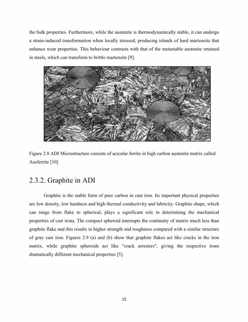
Figure 4.6 Effect of austempering time on Hardness of Ductile Iron with Cu austempered at
different temperatures.
From the figures 4.5 and 4.6 it is evident that the hardness value of ADI increases during
short times of austempering as during the subsequent cooling from austempering temperature to
room temperature the formation of martensite cannot be prevented. As austempering time
increases the carbon content of the austenite increases resulting in a decrease in Ms and Mf
temperatures [Figure 2.5]. With somewhat longer austempering time the amount of retained
austenite increases which results in decrease in hardness. Copper alloyed ADI samples exhibit
lower hardness compared to plain ADI samples.
4.1.3 Impact Test
The variation of toughness with austempering time and temperature for austempered
ductile iron samples without Cu are as shown in the table 4.6.
The as received sample of ductile iron without copper had the toughness (notched Charpy sample) value of 16J.

41
Table4.6 Toughness values for ADI without Cu.
Austempering window Toughness values Temp(°C) Time (Hr) Impact Energy(J)
350 0.5 13 1 16 1.5 20 2 24
300 0.5 13 1 15 1.5 18 2 20
250 0.5 12 1 13 1.5 17 2 18
Figure 4.7 Effect of austempering time on Impact Toughness of Ductile Iron without Cu austempered at different temperatures.

42
The toughness values for notched samples were found to increase with increasing
austempering time and increasing austempering temperatures due to the increase in ductility seen
in such samples.
The variation of toughness with austempering time and temperature for austempered
ductile iron samples with Cu are as shown in the table 4.7.
The as received sample of ductile iron with copper had the toughness (notched Charpy sample) value of 10 J.
Table 4.7 Toughness values for ADI with Cu.
Austempering window Toughness values Temp(°C) Time (Hr) Impact Energy(J)
350 0.5 24 1 37 1.5 40 2 45
300 0.5 22 1 34 1.5 38 2 41
250 0.5 21 1 31 1.5 35 2 37

43
Figure 4.8 Effect of austempering time on Impact Toughness of Ductile Iron with Cu austempered at different temperatures.
The toughness values for notched ADI samples with copper similarly increased with
increasing austempering time and higher austempering temperatures as in plain ADI samples
because of greater ductility of the samples austempered for longer times and at higher
temperatures. Copper alloyed ADI samples exhibited higher toughness values compared to plain
ADI because of the effect of copper in stabilizing the austenite during austempering resulting in
higher ductility [27].
4.2. Microstructural observations
The microstructures of ductile iron samples with and without copper austempered at 350°C were
studied under scanning electron microscope with 550x magnification.

44
(a) (b)
Figure 4.9 SEM microstructures of ADI austempered at 350°C for 1.5 hrs (a) without copper (b) with copper.
As seen in Figure 4.9 the heat-treated microstructures of both materials consist of
graphite nodules of different sizes in the matrix phase. From the microstructures it was seen that
copper addition does not cause any observable change to the austempered microstructure of plain
ADI. In some cases the copper is associated with the graphite nodules, but not necessarily as a
thin film.
Conclusions

45
5. Conclusions From the study on the effect of austempering temperature, time and copper addition on
the mechanical properties of austempered ductile iron the following conclusions could be drawn
1. Austempering significantly enhances the tensile strength of Ductile Iron with and without
copper additions and higher tensile strength was obtained in samples austempered at
lower temperatures of 250°C.
2. Ductility of Austempered Ductile Iron was found to increase with increasing
austempering time and maximum ductility was seen in samples austempered up to 1.5
hours.
3. Addition of copper significantly increases the ductility of Austempered Ductile Iron with
a slight decrease in tensile strength.
4. Hardness of both the plain ADI and copper alloyed ADI samples were found to increase
with decreasing austempering temperature and time.
5. Toughness of ADI increases with increasing time and temperature of austempering
treatment and was significantly higher in case of ADI samples with copper.

Future Work

46
6. Future work Austempered ductile iron has found enormous applications in recent years due to its high
strength and hardness, with good toughness. It has started to replace steel in some structural and
engineering applications. More work is needed to improve the properties like corrosion
resistance, relative abrasive resistance and hardenability of ductile iron through studies on the
effect of different alloying elements and heat treatment processes on the ductile iron.

References

47
References [1] Hughes I.C.H, “Austempered Ductile Irons - Their Properties & Significance”,
Materials & Design, Vol-6, No-3, 1985, 124-126.
[2] W.F. Smith, “Structure and Properties of Engineering Alloys”, second ed. Mc
Graw-Hill, 1993.
[3] Labreeque C & Gagne M. “Reviewed of Ductile Iron: Fifty years of Continuous
Development”, Canadian Metallurgical Quarterly, 37, 5, 1998 343-378.
[4] Singh V, “Physical Metallurgy”, Standard Publishers Distributors, 1999.
[5] Mullin J.D, “Ductile iron data for design engineers”, Rio tinto iron & titanium
inc., Montreal, Quebec, Canada, 1990.
[6] Rajan T.V, Sharma C.P, Sharma A, “Heat treatments-Principles and techniques”,
PHI, New Delhi, 2006.
[7] Davis J.R& associates, “Cast iron”, ASM Society Hand book, 1996.
[8] Kim Yoon-Jun, Shin Hochoel, “Investigation into mechanical properties of
austempered ductile cast iron (ADI) in accordance with austempering
temperature”, Materials Letters, Vol. 62, 2006, 357-360.
[9] “Austempered ductile iron”, http://www.aditreatments.com.
[10] Keough J. R, Hayrynen K. L, “Austempered cast irons”, Applied Process, Inc.,
Livonia, Michigan, 2004.
[11] Kustuv A, Taran Y, Uzlov J, Krimmel A, Evsyukov M, “Formation of bainite in
ductile iron”, Materials Science and Engineering, A 273-275, 1999, 480-484.

48
[12] Taran Y.N, Uzlov K.I, Kustuv, Bainitic reaction kinetics in austempered ductile
iron, A.Y, J Phys. (Fr.) IV 7, 1997, C 5-429.
[13] P.W. Shelton, A.A.Bonner, “The effect of copper addition to the mechanical
properties of austempered ductile iron (ADI)”, Material Processing Technology,
173, 2006, 269-274.
[14] Olivera Eric, Milan Jovanovic, Leposava S, Dragan Rajnovic, Slavica Zec, “The
austempering study of alloyed ductile iron”, Materials and Design, 27, 2006, 617-
622.
[15] Advanced cast products, http://www.advancedcast.com/adi-advantages.htm.
[16] http://www.durhamfoundry.com/austempered_ductile_iron.htm.
[17] http://www.wmlee.co.uk.
[18] Harding R. 2nd International conference on austempered ductile ASME gear
research institute. Ann Arbor (MI): ASME Gear Research Institute; 1986, 39-54.
[19] Kovacs B. Trans AFS 1990; 103:38.
[20] Mullin JD. “The market of ductile iron casting is still growing”, Sorelmetal
review, 83, 2006.
[21] Radzikowska J.M, “Effect of specimen preparation on evaluation of cast iron
microstructure”, Materials characterization, 54, 2005, 287-304.
[22] Donald C. Zipperian, “Metallographic Specimen Preparation Basics”, Pace
technology, 2001.
[23] Hafiz M, “Mechanical properties of SG iron subjected to variable and isothermal
Austempering temperatures heat treatment”, Materials science and engineering,
A340, 2003, 1-7.

49
[24] Dubal G.P, “Salt bath quenching”, Advanced materials & processes, 1999.
[25] Foreman R.W, “New developments in salt bath quenching”, Industrial heating,
1993 Vol. 60 (3), 41-47.
[26] Abdel-Hakim H.A., Attia A.A., Baraka A.M, “Dissolution susceptibility of oxide
species formed on mild steel during its oxidation in molten KNO3-NaNO3 eutectic
mixture”, Journal of Materials Engineering and performance, Vol. 11(3) 2002,
301-305.
[27] Silman G. I, Kamynin V.V, Goncharov V. V, “On the mechanism of copper effect on the structure formation in cast iron”, Material Science and Heat Treatment, vol. 49, 2007, 7-8.
Related Documents