Ý. KIRIK, N. ÖZDEMÝR: EFFECT OF PROCESS PARAMETERS ON THE MICROSTRUCTURE ... 825–832 EFFECT OF PROCESS PARAMETERS ON THE MICROSTRUCTURE AND MECHANICAL PROPERTIES OF FRICTION-WELDED JOINTS OF AISI 1040/AISI 304L STEELS VPLIV PROCESNIH PARAMETROV NA MIKROSTRUKTURO IN MEHANSKE LASTNOSTI TORNO VARJENIH SPOJEV JEKEL AISI 1040/AISI 304L Ýhsan Kirik 1 , Niyazi Özdemýr 2 1 Batman University, Department of Metallurgy and Material Engineering, 72060 Batman, Turkey 2 Fýrat University, Department of Metallurgy and Materials Engineering, 23119 Elazýð, Turkey alihsankirik@gmail.com Prejem rokopisa – received: 2014-09-17; sprejem za objavo – accepted for publication: 2014-10-17 doi:10.17222/mit.2014.235 Couples of AISI 304L and AISI 1040 steels were welded using the continuous-drive friction-welding process. The welded joints were manufactured using three different rotational speeds ((1300, 1500 and 1700) r/min), three different frictional pressures and three different frictional times. To determine microstructural changes, the interface regions of the welded samples were examined by scanning electron microscopy (SEM), X-ray diffraction (XRD) and energy dispersive spectrometry (EDS). Microhardness and tensile tests of the welded samples were conducted. The results show that the properties of the microstructures are significantly changed and the interface temperature increased with the frictional time. An excellent tensile strength was observed for the joint made at a rotational speed of 1700 r/min and a frictional time of 4 s. Keywords: friction welding, AISI 1040 steel, AISI 304L steel Jekli AISI 304L in AISI 1040 sta bili zvarjeni z uporabo kontinuirnega tornega procesa varjenja. Zvarjeni spoji so bili izdelani pri treh razli~nih hitrostih vrtenja ((1300, 1500 in 1700) r/min), treh razli~nih tornih tlakih in treh razli~nih tornih ~asih. Za dolo~itev mikrostrukturnih sprememb je bilo sti~no podro~je zvarjenega vzorca preiskano z vrsti~nim elektronskim mikroskopom (SEM), z rentgensko difrakcijo (XRD) in z energijsko disperzijsko rentgensko spektrometrijo (EDS). Izvr{eni so bili preizkusi mikrotrdote in natezni preizkusi varjenih vzorcev. Rezultati ka`ejo, da se mikrostruktura omembe vredno spremeni in da se temperatura stika povi{uje s ~asom trenja. Odli~na natezna trdnost stika je bila ugotovljena pri spoju s hitrostjo vrtenja 1700 r/min in pri tornem ~asu 4 s. Klju~ne besede: torno varjenje, jeklo AISI 1040, jeklo AISI 304L 1 INTRODUCTION Stainless steels are iron-based alloys containing 8–25 % nickel and 12–30 % chromium, resisting both corrosion and high temperature. Generally, stainless steels can be classified as martensitic, ferritic and austenitic. Auste- nitic stainless steels represent the largest group of stainless steels and are produced in higher tonnages than any other group. They have a good corrosion resistance in most environments. Austenitic stainless steel can be strengthened significantly by cold working and are often used in the applications requiring a good atmospheric or elevated-temperature corrosion resistance. In spite of a wide variety of austenitic stainless steel, the 300-series alloys, based on the 18Cr-8Ni system, are the oldest and most commonly used. 1–5 Type 304 is the foundation of this alloy series and, along with 304L, it represents the most commonly selected austenitic grade. Although austenitic alloys are generally considered to be very weldable, they are subjected to a number of weld- ability problems if proper precautions are not taken. Liquation cracking and weld solidification may occur depending on the composition of the base, the filler metal and the level of impurities, particularly S and P. In spite of the good general corrosion resistance of auste- nitic stainless steels, they may be subject to localized forms of corrosion at grain boundaries and in the heat- affected zone. For joining dissimilar materials, conven- tional fusion welding is used. However, this method has a lower efficiency when compared to the friction-weld- ing method. 5–7 The friction-welding process is a solid-state welding process producing welds due to a compressive-force con- tact of two workpieces: one is rotating and the other is stationary. 8,9 The heat is generated at the weld interface due to a continuous rubbing of the contact surfaces, while the temperature rises and softens the material. Eventually, the material at the interface starts to flow pla- stically and forms an upsetting. When a certain amount of upsetting occurs, the rotation is stopped and the compressive force is maintained or slightly increased to consolidate the joint. The fundamental parameters of the friction-welding (FW) process are the rotational speed, the frictional pressure and time, and the forging pressure and time. The advantages of friction welding are a high material saving, a short production time and the possi- Materiali in tehnologije / Materials and technology 49 (2015) 5, 825–832 825 UDK 621.791/.792:620.17:620.187:669.14 ISSN 1580-2949 Professional article/Strokovni ~lanek MTAEC9, 49(5)825(2015)

Welcome message from author
This document is posted to help you gain knowledge. Please leave a comment to let me know what you think about it! Share it to your friends and learn new things together.
Transcript
Ý. KIRIK, N. ÖZDEMÝR: EFFECT OF PROCESS PARAMETERS ON THE MICROSTRUCTURE ...825–832
EFFECT OF PROCESS PARAMETERS ON THEMICROSTRUCTURE AND MECHANICAL PROPERTIES OF
FRICTION-WELDED JOINTS OF AISI 1040/AISI 304L STEELS
VPLIV PROCESNIH PARAMETROV NA MIKROSTRUKTURO INMEHANSKE LASTNOSTI TORNO VARJENIH SPOJEV JEKEL
AISI 1040/AISI 304L
Ýhsan Kirik1, Niyazi Özdemýr2
1Batman University, Department of Metallurgy and Material Engineering, 72060 Batman, Turkey2Fýrat University, Department of Metallurgy and Materials Engineering, 23119 Elazýð, Turkey
Prejem rokopisa – received: 2014-09-17; sprejem za objavo – accepted for publication: 2014-10-17
doi:10.17222/mit.2014.235
Couples of AISI 304L and AISI 1040 steels were welded using the continuous-drive friction-welding process. The welded jointswere manufactured using three different rotational speeds ((1300, 1500 and 1700) r/min), three different frictional pressures andthree different frictional times. To determine microstructural changes, the interface regions of the welded samples wereexamined by scanning electron microscopy (SEM), X-ray diffraction (XRD) and energy dispersive spectrometry (EDS).Microhardness and tensile tests of the welded samples were conducted. The results show that the properties of themicrostructures are significantly changed and the interface temperature increased with the frictional time. An excellent tensilestrength was observed for the joint made at a rotational speed of 1700 r/min and a frictional time of 4 s.Keywords: friction welding, AISI 1040 steel, AISI 304L steel
Jekli AISI 304L in AISI 1040 sta bili zvarjeni z uporabo kontinuirnega tornega procesa varjenja. Zvarjeni spoji so bili izdelanipri treh razli~nih hitrostih vrtenja ((1300, 1500 in 1700) r/min), treh razli~nih tornih tlakih in treh razli~nih tornih ~asih. Zadolo~itev mikrostrukturnih sprememb je bilo sti~no podro~je zvarjenega vzorca preiskano z vrsti~nim elektronskimmikroskopom (SEM), z rentgensko difrakcijo (XRD) in z energijsko disperzijsko rentgensko spektrometrijo (EDS). Izvr{eni sobili preizkusi mikrotrdote in natezni preizkusi varjenih vzorcev. Rezultati ka`ejo, da se mikrostruktura omembe vrednospremeni in da se temperatura stika povi{uje s ~asom trenja. Odli~na natezna trdnost stika je bila ugotovljena pri spoju shitrostjo vrtenja 1700 r/min in pri tornem ~asu 4 s.Klju~ne besede: torno varjenje, jeklo AISI 1040, jeklo AISI 304L
1 INTRODUCTION
Stainless steels are iron-based alloys containing 8–25 %nickel and 12–30 % chromium, resisting both corrosionand high temperature. Generally, stainless steels can beclassified as martensitic, ferritic and austenitic. Auste-nitic stainless steels represent the largest group ofstainless steels and are produced in higher tonnages thanany other group. They have a good corrosion resistancein most environments. Austenitic stainless steel can bestrengthened significantly by cold working and are oftenused in the applications requiring a good atmospheric orelevated-temperature corrosion resistance.
In spite of a wide variety of austenitic stainless steel,the 300-series alloys, based on the 18Cr-8Ni system, arethe oldest and most commonly used.1–5 Type 304 is thefoundation of this alloy series and, along with 304L, itrepresents the most commonly selected austenitic grade.Although austenitic alloys are generally considered to bevery weldable, they are subjected to a number of weld-ability problems if proper precautions are not taken.Liquation cracking and weld solidification may occurdepending on the composition of the base, the filler
metal and the level of impurities, particularly S and P. Inspite of the good general corrosion resistance of auste-nitic stainless steels, they may be subject to localizedforms of corrosion at grain boundaries and in the heat-affected zone. For joining dissimilar materials, conven-tional fusion welding is used. However, this method hasa lower efficiency when compared to the friction-weld-ing method.5–7
The friction-welding process is a solid-state weldingprocess producing welds due to a compressive-force con-tact of two workpieces: one is rotating and the other isstationary.8,9 The heat is generated at the weld interfacedue to a continuous rubbing of the contact surfaces,while the temperature rises and softens the material.Eventually, the material at the interface starts to flow pla-stically and forms an upsetting. When a certain amountof upsetting occurs, the rotation is stopped and thecompressive force is maintained or slightly increased toconsolidate the joint. The fundamental parameters of thefriction-welding (FW) process are the rotational speed,the frictional pressure and time, and the forging pressureand time. The advantages of friction welding are a highmaterial saving, a short production time and the possi-
Materiali in tehnologije / Materials and technology 49 (2015) 5, 825–832 825
UDK 621.791/.792:620.17:620.187:669.14 ISSN 1580-2949Professional article/Strokovni ~lanek MTAEC9, 49(5)825(2015)
bility of joining different metals or alloys. This methodcan also be used to join the components that have circu-lar or non-circular cross-sections.10–17
In this study, parts of the AISI 304L austenitic stain-less steel and AISI 1040 carbon steel with equal dia-meters were welded using the friction-welding method.The strengths of the joints were determined with tensiletests and compared with those of the base materials.Then, the hardness variations and microstructures of thewelding zones were obtained and investigated usingmacro- and microphotographs.
2 EXPERIMENTAL PROCEDURES
The workpieces used in this work were Ø 12 mmrods of AISI 1040 and AISI 304L austenitic stainlesssteels. The nominal chemical compositions and mechani-cal properties of the materials used are shown in Tables1 and 2, respectively. The AISI 1040 medium-carbonsteel and the AISI 304L austenitic stainless steel werejoined with a PLC-controlled continuous-drive friction-welding machine using different rotational speeds,frictional times and frictional pressures, as indicated inTable 3. The temperature of the welded zone during the
Ý. KIRIK, N. ÖZDEMÝR: EFFECT OF PROCESS PARAMETERS ON THE MICROSTRUCTURE ...
826 Materiali in tehnologije / Materials and technology 49 (2015) 5, 825–832
Table 1: Chemical compositions of test materials in mass fractionsTabela 1: Kemijska sestava materialov za preizkuse v masnih dele`ih
MaterialsAlloying elements (w/%)
C Mn P S Cr Mo Ni FeAISI 1040 0.37–0.44 0.60–0.90 0.040 0.050 – – – BalanceAISI 304L 0.042 1.47 0.032 0.032 18.25 0.30 8.09 Balance
Table 2: Mechanical properties of parent materialsTabela 2: Mehanske lastnosti izhodnih materialov
Material Hardness (HV) Yield strength (MPa) Tensile strength (MPa)AISI 1040 165 215 630AISI 304L 210 380 700
Table 3: Process parameters used in friction weldingTabela 3: Procesni parametri, uporabljeni pri tornem varjenju
Samp. No
Welding parametersRotational
speed(r/min)
Frictionaltime(s)
Frictionalpressure(MPa)
Forgingpressure(MPa)
Forgingtime(s)
Axial short.(mm)
Max. temp.(oC)
Max.hardness
(HV)
Max. tensilestren.(MPa)
S1 1300 8 30 60 4 6 1204 362 371.414S2 1300 8 40 80 4 7 1189 311 412.431S3 1300 8 50 100 4 8 1105 400 483.223S4 1300 6 30 60 3 5 1176 348 387.026S5 1300 6 40 80 3 6 1102 317 559.276S6 1300 6 50 100 3 7 1152 312 600.061S7 1300 4 30 60 2 4 1214 330 580.338S8 1300 4 40 80 2 5 1124 277 599.821S9 1300 4 50 100 2 6 1182 254 617.106
S10 1500 8 30 60 4 7 1175 320 473.096S11 1500 8 40 80 4 8 1104 376 575.716S12 1500 8 50 100 4 9 1123 329 596.613S13 1500 6 40 60 3 6 1140 319 588.216S14 1500 6 40 80 3 7 1164 337 599.296S15 1500 6 50 100 3 8 1129 278 611.714S16 1500 4 30 60 2 4.5 1104 356 586.311S17 1500 4 40 80 2 5.5 1185 361 603.196S18 1500 4 50 100 2 6 1075 256 588.807S19 1700 8 30 60 4 8 1089 321 531.222S20 1700 8 40 80 4 9 1067 342 563.691S21 1700 8 50 100 4 10 1075 263 568.780S22 1700 6 30 60 3 7 1125 349 573.808S23 1700 6 40 80 3 7.5 1093 322 589.467S24 1700 6 50 100 3 8.5 1143 245 571.993S25 1700 4 30 60 2 4.5 1089 364 592.684S26 1700 4 40 80 2 5.5 1092 300 612.923S27 1700 4 50 100 2 6.5 1047 210 637.500
welding process was measured with an IGA 15 PLUSdevice. After the friction welding, the microstructuralchanges in the interface regions of the joints wereexamined with scanning electron microscopy (SEM),X-ray diffraction (XRD) and energy dispersive spectro-metry (EDS). Microhardness and tensile tests were con-
ducted and the fracture surfaces of the tensile-testsamples were investigated.
3 RESULTS AND DISCUSSIONS
3.1 Evaluation of macro- and microstructural proper-ties
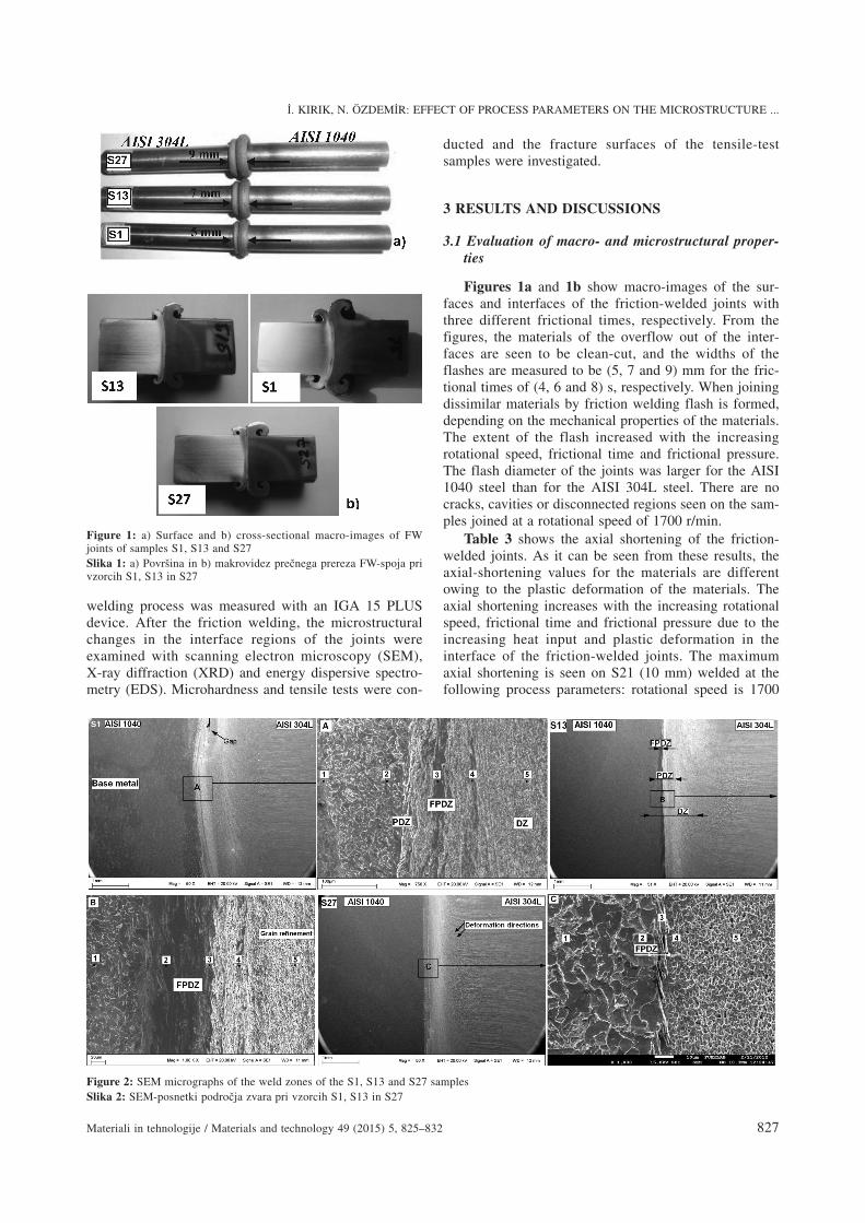
Figures 1a and 1b show macro-images of the sur-faces and interfaces of the friction-welded joints withthree different frictional times, respectively. From thefigures, the materials of the overflow out of the inter-faces are seen to be clean-cut, and the widths of theflashes are measured to be (5, 7 and 9) mm for the fric-tional times of (4, 6 and 8) s, respectively. When joiningdissimilar materials by friction welding flash is formed,depending on the mechanical properties of the materials.The extent of the flash increased with the increasingrotational speed, frictional time and frictional pressure.The flash diameter of the joints was larger for the AISI1040 steel than for the AISI 304L steel. There are nocracks, cavities or disconnected regions seen on the sam-ples joined at a rotational speed of 1700 r/min.
Table 3 shows the axial shortening of the friction-welded joints. As it can be seen from these results, theaxial-shortening values for the materials are differentowing to the plastic deformation of the materials. Theaxial shortening increases with the increasing rotationalspeed, frictional time and frictional pressure due to theincreasing heat input and plastic deformation in theinterface of the friction-welded joints. The maximumaxial shortening is seen on S21 (10 mm) welded at thefollowing process parameters: rotational speed is 1700
Ý. KIRIK, N. ÖZDEMÝR: EFFECT OF PROCESS PARAMETERS ON THE MICROSTRUCTURE ...
Materiali in tehnologije / Materials and technology 49 (2015) 5, 825–832 827
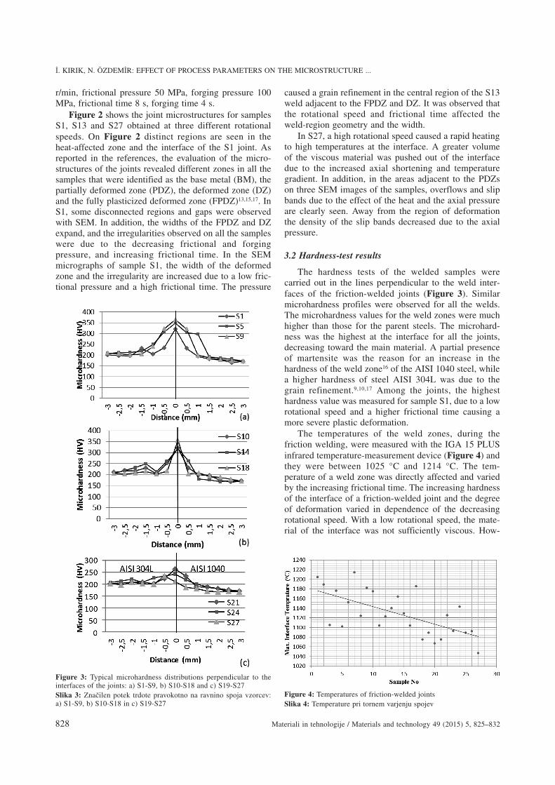
Figure 2: SEM micrographs of the weld zones of the S1, S13 and S27 samplesSlika 2: SEM-posnetki podro~ja zvara pri vzorcih S1, S13 in S27
Figure 1: a) Surface and b) cross-sectional macro-images of FWjoints of samples S1, S13 and S27Slika 1: a) Povr{ina in b) makrovidez pre~nega prereza FW-spoja privzorcih S1, S13 in S27
r/min, frictional pressure 50 MPa, forging pressure 100MPa, frictional time 8 s, forging time 4 s.
Figure 2 shows the joint microstructures for samplesS1, S13 and S27 obtained at three different rotationalspeeds. On Figure 2 distinct regions are seen in theheat-affected zone and the interface of the S1 joint. Asreported in the references, the evaluation of the micro-structures of the joints revealed different zones in all thesamples that were identified as the base metal (BM), thepartially deformed zone (PDZ), the deformed zone (DZ)and the fully plasticized deformed zone (FPDZ)13,15,17. InS1, some disconnected regions and gaps were observedwith SEM. In addition, the widths of the FPDZ and DZexpand, and the irregularities observed on all the sampleswere due to the decreasing frictional and forgingpressure, and increasing frictional time. In the SEMmicrographs of sample S1, the width of the deformedzone and the irregularity are increased due to a low fric-tional pressure and a high frictional time. The pressure
caused a grain refinement in the central region of the S13weld adjacent to the FPDZ and DZ. It was observed thatthe rotational speed and frictional time affected theweld-region geometry and the width.
In S27, a high rotational speed caused a rapid heatingto high temperatures at the interface. A greater volumeof the viscous material was pushed out of the interfacedue to the increased axial shortening and temperaturegradient. In addition, in the areas adjacent to the PDZson three SEM images of the samples, overflows and slipbands due to the effect of the heat and the axial pressureare clearly seen. Away from the region of deformationthe density of the slip bands decreased due to the axialpressure.
3.2 Hardness-test results
The hardness tests of the welded samples werecarried out in the lines perpendicular to the weld inter-faces of the friction-welded joints (Figure 3). Similarmicrohardness profiles were observed for all the welds.The microhardness values for the weld zones were muchhigher than those for the parent steels. The microhard-ness was the highest at the interface for all the joints,decreasing toward the main material. A partial presenceof martensite was the reason for an increase in thehardness of the weld zone16 of the AISI 1040 steel, whilea higher hardness of steel AISI 304L was due to thegrain refinement.9,10,17 Among the joints, the highesthardness value was measured for sample S1, due to a lowrotational speed and a higher frictional time causing amore severe plastic deformation.
The temperatures of the weld zones, during thefriction welding, were measured with the IGA 15 PLUSinfrared temperature-measurement device (Figure 4) andthey were between 1025 °C and 1214 °C. The tem-perature of a weld zone was directly affected and variedby the increasing frictional time. The increasing hardnessof the interface of a friction-welded joint and the degreeof deformation varied in dependence of the decreasingrotational speed. With a low rotational speed, the mate-rial of the interface was not sufficiently viscous. How-
Ý. KIRIK, N. ÖZDEMÝR: EFFECT OF PROCESS PARAMETERS ON THE MICROSTRUCTURE ...
828 Materiali in tehnologije / Materials and technology 49 (2015) 5, 825–832
Figure 4: Temperatures of friction-welded jointsSlika 4: Temperature pri tornem varjenju spojev
Figure 3: Typical microhardness distributions perpendicular to theinterfaces of the joints: a) S1-S9, b) S10-S18 and c) S19-S27Slika 3: Zna~ilen potek trdote pravokotno na ravnino spoja vzorcev:a) S1-S9, b) S10-S18 in c) S19-S27
ever, looking at the hardness values for all the samples,the hardness values for the AISI 304L austenitic stainlesssteels were higher than for the AISI 1040 medium-carbon steels due to the deformation hardening. Themain reasons for this difference are the heat-transfercapacity and the yield strength of the stainless steels thatare 60 % higher than those of the medium-carbonsteels.18,19 The lowest hardness and the lowest tempera-ture were obtained for specimen S27, at the rotationalspeed of 1700 r/min, frictional pressure of 50 MPa andfrictional time of 4 s.
3.3 Tensile-test results
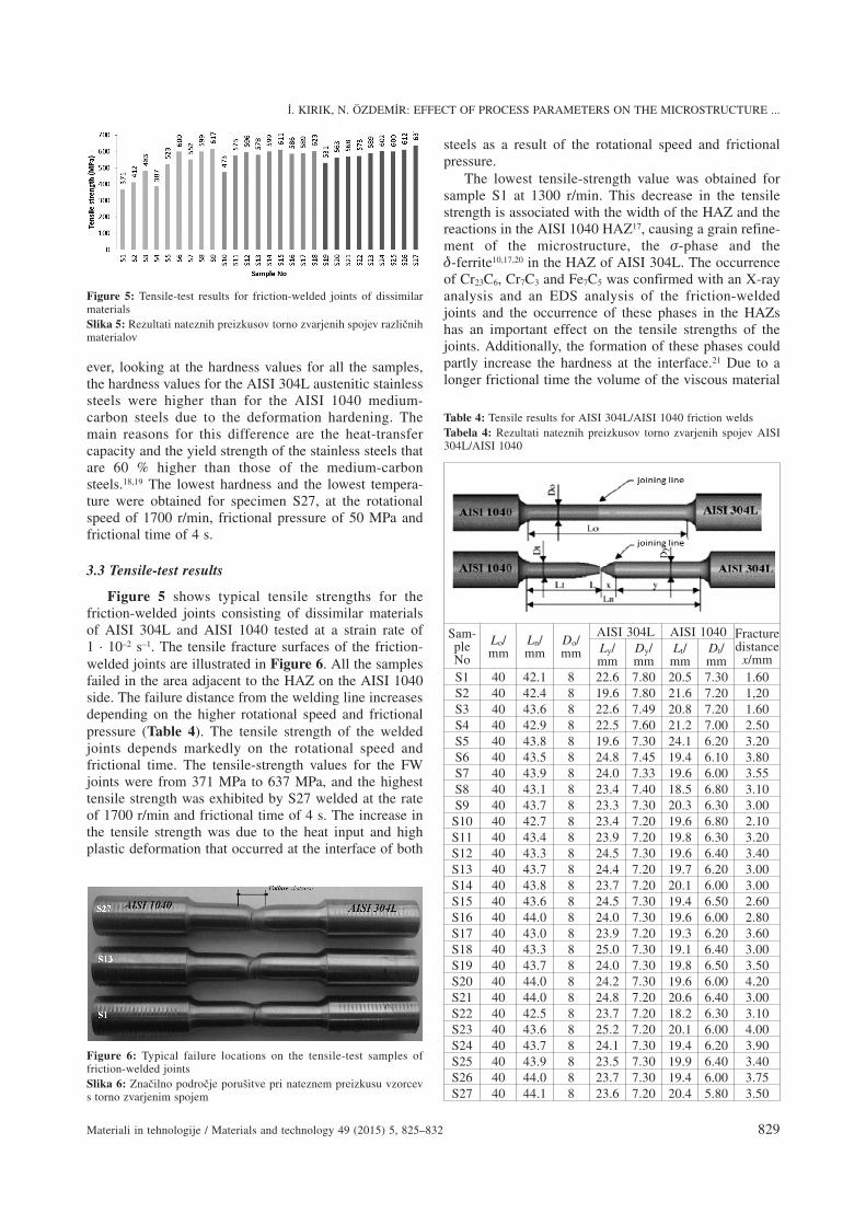
Figure 5 shows typical tensile strengths for thefriction-welded joints consisting of dissimilar materialsof AISI 304L and AISI 1040 tested at a strain rate of1 · 10–2 s–1. The tensile fracture surfaces of the friction-welded joints are illustrated in Figure 6. All the samplesfailed in the area adjacent to the HAZ on the AISI 1040side. The failure distance from the welding line increasesdepending on the higher rotational speed and frictionalpressure (Table 4). The tensile strength of the weldedjoints depends markedly on the rotational speed andfrictional time. The tensile-strength values for the FWjoints were from 371 MPa to 637 MPa, and the highesttensile strength was exhibited by S27 welded at the rateof 1700 r/min and frictional time of 4 s. The increase inthe tensile strength was due to the heat input and highplastic deformation that occurred at the interface of both
steels as a result of the rotational speed and frictionalpressure.
The lowest tensile-strength value was obtained forsample S1 at 1300 r/min. This decrease in the tensilestrength is associated with the width of the HAZ and thereactions in the AISI 1040 HAZ17, causing a grain refine-ment of the microstructure, the �-phase and the�-ferrite10,17,20 in the HAZ of AISI 304L. The occurrenceof Cr23C6, Cr7C3 and Fe7C5 was confirmed with an X-rayanalysis and an EDS analysis of the friction-weldedjoints and the occurrence of these phases in the HAZshas an important effect on the tensile strengths of thejoints. Additionally, the formation of these phases couldpartly increase the hardness at the interface.21 Due to alonger frictional time the volume of the viscous material
Ý. KIRIK, N. ÖZDEMÝR: EFFECT OF PROCESS PARAMETERS ON THE MICROSTRUCTURE ...
Materiali in tehnologije / Materials and technology 49 (2015) 5, 825–832 829
Figure 6: Typical failure locations on the tensile-test samples offriction-welded jointsSlika 6: Zna~ilno podro~je poru{itve pri nateznem preizkusu vzorcevs torno zvarjenim spojem
Figure 5: Tensile-test results for friction-welded joints of dissimilarmaterialsSlika 5: Rezultati nateznih preizkusov torno zvarjenih spojev razli~nihmaterialov
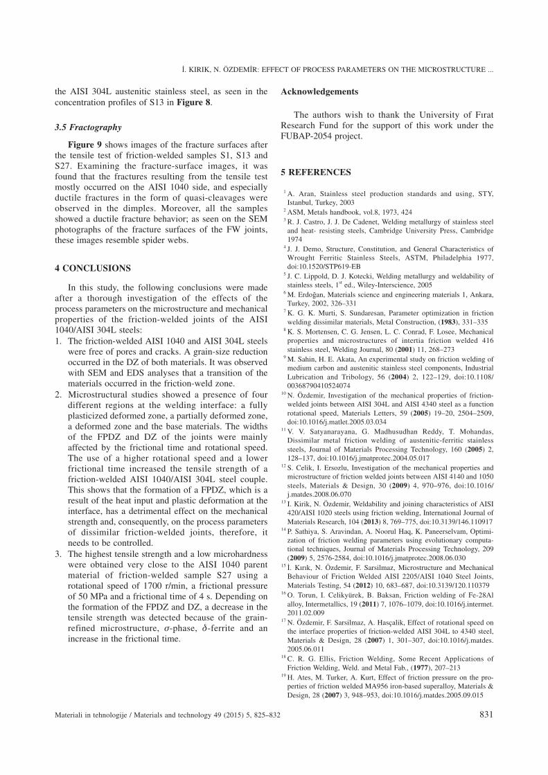
Table 4: Tensile results for AISI 304L/AISI 1040 friction weldsTabela 4: Rezultati nateznih preizkusov torno zvarjenih spojev AISI304L/AISI 1040
Sam-pleNo
Lo/mm
Ln/mm
Do/mm
AISI 304L AISI 1040 Fracturedistance
x/mmLy/mm
Dy/mm
Lt/mm
Dt/mm
S1 40 42.1 8 22.6 7.80 20.5 7.30 1.60S2 40 42.4 8 19.6 7.80 21.6 7.20 1,20S3 40 43.6 8 22.6 7.49 20.8 7.20 1.60S4 40 42.9 8 22.5 7.60 21.2 7.00 2.50S5 40 43.8 8 19.6 7.30 24.1 6.20 3.20S6 40 43.5 8 24.8 7.45 19.4 6.10 3.80S7 40 43.9 8 24.0 7.33 19.6 6.00 3.55S8 40 43.1 8 23.4 7.40 18.5 6.80 3.10S9 40 43.7 8 23.3 7.30 20.3 6.30 3.00
S10 40 42.7 8 23.4 7.20 19.6 6.80 2.10S11 40 43.4 8 23.9 7.20 19.8 6.30 3.20S12 40 43.3 8 24.5 7.30 19.6 6.40 3.40S13 40 43.7 8 24.4 7.20 19.7 6.20 3.00S14 40 43.8 8 23.7 7.20 20.1 6.00 3.00S15 40 43.6 8 24.5 7.30 19.4 6.50 2.60S16 40 44.0 8 24.0 7.30 19.6 6.00 2.80S17 40 43.0 8 23.9 7.20 19.3 6.20 3.60S18 40 43.3 8 25.0 7.30 19.1 6.40 3.00S19 40 43.7 8 24.0 7.30 19.8 6.50 3.50S20 40 44.0 8 24.2 7.30 19.6 6.00 4.20S21 40 44.0 8 24.8 7.20 20.6 6.40 3.00S22 40 42.5 8 23.7 7.20 18.2 6.30 3.10S23 40 43.6 8 25.2 7.20 20.1 6.00 4.00S24 40 43.7 8 24.1 7.30 19.4 6.20 3.90S25 40 43.9 8 23.5 7.30 19.9 6.40 3.40S26 40 44.0 8 23.7 7.30 19.4 6.00 3.75S27 40 44.1 8 23.6 7.20 20.4 5.80 3.50
transferred at the weld interface decreased and the tensilestrength was lowered (Figure 5). On the other hand, thetensile strength increased with a higher rotational speedand a lower frictional time. This shows that the forma-tion and the width of the FPDZ, which is a result of theheat input and plastic deformation at the interface, havedetrimental effects on the mechanical strength and,
consequently, on the process parameters of dissimilarfriction-welded joints.
3.4 X-ray and EDS analyses
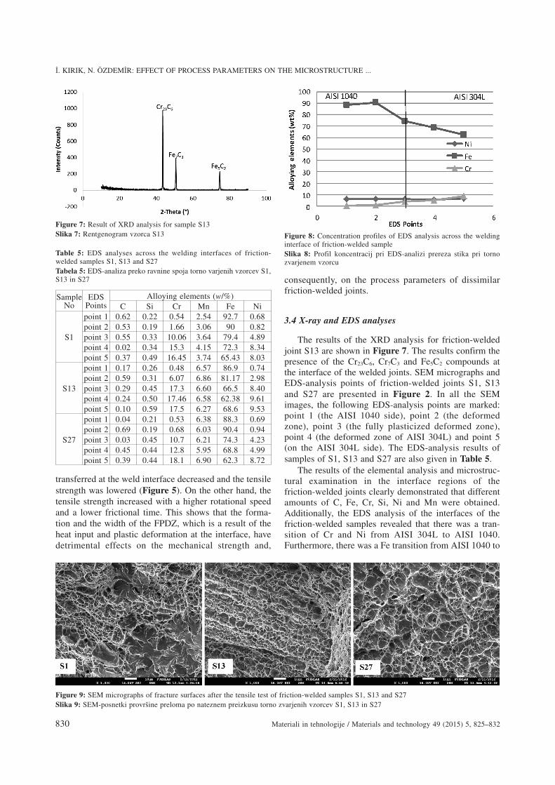
The results of the XRD analysis for friction-weldedjoint S13 are shown in Figure 7. The results confirm thepresence of the Cr23C6, Cr7C3 and Fe5C2 compounds atthe interface of the welded joints. SEM micrographs andEDS-analysis points of friction-welded joints S1, S13and S27 are presented in Figure 2. In all the SEMimages, the following EDS-analysis points are marked:point 1 (the AISI 1040 side), point 2 (the deformedzone), point 3 (the fully plasticized deformed zone),point 4 (the deformed zone of AISI 304L) and point 5(on the AISI 304L side). The EDS-analysis results ofsamples of S1, S13 and S27 are also given in Table 5.
The results of the elemental analysis and microstruc-tural examination in the interface regions of thefriction-welded joints clearly demonstrated that differentamounts of C, Fe, Cr, Si, Ni and Mn were obtained.Additionally, the EDS analysis of the interfaces of thefriction-welded samples revealed that there was a tran-sition of Cr and Ni from AISI 304L to AISI 1040.Furthermore, there was a Fe transition from AISI 1040 to
Ý. KIRIK, N. ÖZDEMÝR: EFFECT OF PROCESS PARAMETERS ON THE MICROSTRUCTURE ...
830 Materiali in tehnologije / Materials and technology 49 (2015) 5, 825–832
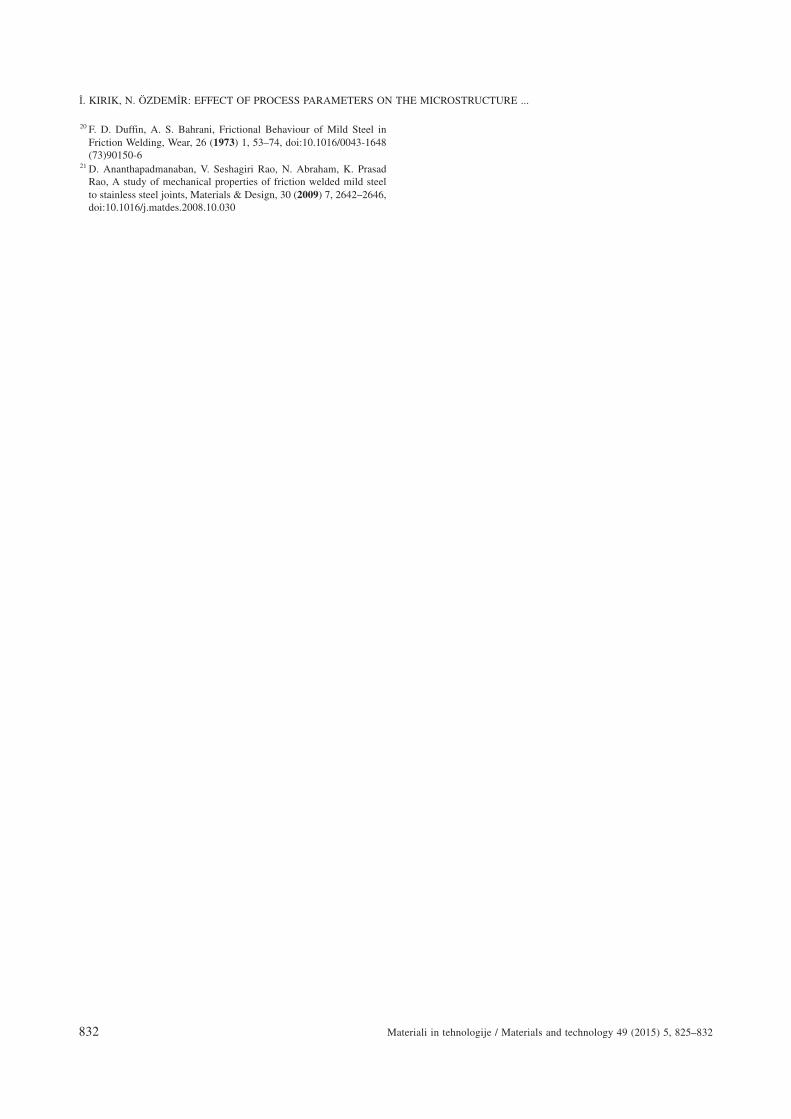
Figure 9: SEM micrographs of fracture surfaces after the tensile test of friction-welded samples S1, S13 and S27Slika 9: SEM-posnetki provr{ine preloma po nateznem preizkusu torno zvarjenih vzorcev S1, S13 in S27
Figure 8: Concentration profiles of EDS analysis across the weldinginterface of friction-welded sampleSlika 8: Profil koncentracij pri EDS-analizi prereza stika pri tornozvarjenem vzorcu
Figure 7: Result of XRD analysis for sample S13Slika 7: Rentgenogram vzorca S13
Table 5: EDS analyses across the welding interfaces of friction-welded samples S1, S13 and S27Tabela 5: EDS-analiza preko ravnine spoja torno varjenih vzorcev S1,S13 in S27
SampleNo
EDSPoints
Alloying elements (w/%)C Si Cr Mn Fe Ni
S1
point 1 0.62 0.22 0.54 2.54 92.7 0.68point 2 0.53 0.19 1.66 3.06 90 0.82point 3 0.55 0.33 10.06 3.64 79.4 4.89point 4 0.02 0.34 15.3 4.15 72.3 8.34point 5 0.37 0.49 16.45 3.74 65.43 8.03
S13
point 1 0.17 0.26 0.48 6.57 86.9 0.74point 2 0.59 0.31 6.07 6.86 81.17 2.98point 3 0.29 0.45 17.3 6.60 66.5 8.40point 4 0.24 0.50 17.46 6.58 62.38 9.61point 5 0.10 0.59 17.5 6.27 68.6 9.53
S27
point 1 0.04 0.21 0.53 6.38 88.3 0.69point 2 0.69 0.19 0.68 6.03 90.4 0.94point 3 0.03 0.45 10.7 6.21 74.3 4.23point 4 0.45 0.44 12.8 5.95 68.8 4.99point 5 0.39 0.44 18.1 6.90 62.3 8.72
the AISI 304L austenitic stainless steel, as seen in theconcentration profiles of S13 in Figure 8.
3.5 Fractography
Figure 9 shows images of the fracture surfaces afterthe tensile test of friction-welded samples S1, S13 andS27. Examining the fracture-surface images, it wasfound that the fractures resulting from the tensile testmostly occurred on the AISI 1040 side, and especiallyductile fractures in the form of quasi-cleavages wereobserved in the dimples. Moreover, all the samplesshowed a ductile fracture behavior; as seen on the SEMphotographs of the fracture surfaces of the FW joints,these images resemble spider webs.
4 CONCLUSIONS
In this study, the following conclusions were madeafter a thorough investigation of the effects of theprocess parameters on the microstructure and mechanicalproperties of the friction-welded joints of the AISI1040/AISI 304L steels:1. The friction-welded AISI 1040 and AISI 304L steels
were free of pores and cracks. A grain-size reductionoccurred in the DZ of both materials. It was observedwith SEM and EDS analyses that a transition of thematerials occurred in the friction-weld zone.
2. Microstructural studies showed a presence of fourdifferent regions at the welding interface: a fullyplasticized deformed zone, a partially deformed zone,a deformed zone and the base materials. The widthsof the FPDZ and DZ of the joints were mainlyaffected by the frictional time and rotational speed.The use of a higher rotational speed and a lowerfrictional time increased the tensile strength of afriction-welded AISI 1040/AISI 304L steel couple.This shows that the formation of a FPDZ, which is aresult of the heat input and plastic deformation at theinterface, has a detrimental effect on the mechanicalstrength and, consequently, on the process parametersof dissimilar friction-welded joints, therefore, itneeds to be controlled.
3. The highest tensile strength and a low microhardnesswere obtained very close to the AISI 1040 parentmaterial of friction-welded sample S27 using arotational speed of 1700 r/min, a frictional pressureof 50 MPa and a frictional time of 4 s. Depending onthe formation of the FPDZ and DZ, a decrease in thetensile strength was detected because of the grain-refined microstructure, �-phase, �-ferrite and anincrease in the frictional time.
Acknowledgements
The authors wish to thank the University of FýratResearch Fund for the support of this work under theFUBAP-2054 project.
5 REFERENCES
1 A. Aran, Stainless steel production standards and using, STY,Istanbul, Turkey, 2003
2 ASM, Metals handbook, vol.8, 1973, 4243 R. J. Castro, J. J. De Cadenet, Welding metallurgy of stainless steel
and heat- resisting steels, Cambridge University Press, Cambridge1974
4 J. J. Demo, Structure, Constitution, and General Characteristics ofWrought Ferritic Stainless Steels, ASTM, Philadelphia 1977,doi:10.1520/STP619-EB
5 J. C. Lippold, D. J. Kotecki, Welding metallurgy and weldability ofstainless steels, 1st ed., Wiley-Interscience, 2005
6 M. Erdoðan, Materials science and engineering materials 1, Ankara,Turkey, 2002, 326–331
7 K. G. K. Murti, S. Sundaresan, Parameter optimization in frictionwelding dissimilar materials, Metal Construction, (1983), 331–335
8 K. S. Mortensen, C. G. Jensen, L. C. Conrad, F. Losee, Mechanicalproperties and microstructures of intertia friction welded 416stainless steel, Welding Journal, 80 (2001) 11, 268–273
9 M. Sahin, H. E. Akata, An experimental study on friction welding ofmedium carbon and austenitic stainless steel components, IndustrialLubrication and Tribology, 56 (2004) 2, 122–129, doi:10.1108/00368790410524074
10 N. Özdemir, Investigation of the mechanical properties of friction-welded joints between AISI 304L and AISI 4340 steel as a functionrotational speed, Materials Letters, 59 (2005) 19–20, 2504–2509,doi:10.1016/j.matlet.2005.03.034
11 V. V. Satyanarayana, G. Madhusudhan Reddy, T. Mohandas,Dissimilar metal friction welding of austenitic-ferritic stainlesssteels, Journal of Materials Processing Technology, 160 (2005) 2,128–137, doi:10.1016/j.jmatprotec.2004.05.017
12 S. Celik, I. Ersozlu, Investigation of the mechanical properties andmicrostructure of friction welded joints between AISI 4140 and 1050steels, Materials & Design, 30 (2009) 4, 970–976, doi:10.1016/j.matdes.2008.06.070
13 I. Kirik, N. Özdemir, Weldability and joining characteristics of AISI420/AISI 1020 steels using friction welding, International Journal ofMaterials Research, 104 (2013) 8, 769–775, doi:10.3139/146.110917
14 P. Sathiya, S. Aravindan, A. Noorul Haq, K. Paneerselvam, Optimi-zation of friction welding parameters using evolutionary computa-tional techniques, Journal of Materials Processing Technology, 209(2009) 5, 2576-2584, doi:10.1016/j.jmatprotec.2008.06.030
15 Ý. Kýrýk, N. Özdemir, F. Sarsilmaz, Microstructure and MechanicalBehaviour of Friction Welded AISI 2205/AISI 1040 Steel Joints,Materials Testing, 54 (2012) 10, 683–687, doi:10.3139/120.110379
16 O. Torun, I. Celikyürek, B. Baksan, Friction welding of Fe-28Alalloy, Intermetallics, 19 (2011) 7, 1076–1079, doi:10.1016/j.intermet.2011.02.009
17 N. Özdemir, F. Sarsilmaz, A. Hasçalik, Effect of rotational speed onthe interface properties of friction-welded AISI 304L to 4340 steel,Materials & Design, 28 (2007) 1, 301–307, doi:10.1016/j.matdes.2005.06.011
18 C. R. G. Ellis, Friction Welding, Some Recent Applications ofFriction Welding, Weld. and Metal Fab., (1977), 207–213
19 H. Ates, M. Turker, A. Kurt, Effect of friction pressure on the pro-perties of friction welded MA956 iron-based superalloy, Materials &Design, 28 (2007) 3, 948–953, doi:10.1016/j.matdes.2005.09.015
Ý. KIRIK, N. ÖZDEMÝR: EFFECT OF PROCESS PARAMETERS ON THE MICROSTRUCTURE ...
Materiali in tehnologije / Materials and technology 49 (2015) 5, 825–832 831
20 F. D. Duffin, A. S. Bahrani, Frictional Behaviour of Mild Steel inFriction Welding, Wear, 26 (1973) 1, 53–74, doi:10.1016/0043-1648(73)90150-6
21 D. Ananthapadmanaban, V. Seshagiri Rao, N. Abraham, K. PrasadRao, A study of mechanical properties of friction welded mild steelto stainless steel joints, Materials & Design, 30 (2009) 7, 2642–2646,doi:10.1016/j.matdes.2008.10.030
Ý. KIRIK, N. ÖZDEMÝR: EFFECT OF PROCESS PARAMETERS ON THE MICROSTRUCTURE ...
832 Materiali in tehnologije / Materials and technology 49 (2015) 5, 825–832
Related Documents