EFFECT OF ADDITION OF CNTs ON PROPERTIES OF CONCRETE A Dissertation submitted In partial Fulfilment of the Requirements for the award of degree of MASTERS OF ENGINEERING IN CIVIL (STRUCTURES) ENGINEERING Submitted by GURPREET SINGH SETHI (ROLL NO. 801222005) Under the guidance of Dr. PREM PAL BANSAL Assistant Professor CIVIL ENGINEERING DEPARTMENT THAPAR UNIVERSITY, PATIALA- 147004 JULY 2014

Welcome message from author
This document is posted to help you gain knowledge. Please leave a comment to let me know what you think about it! Share it to your friends and learn new things together.
Transcript

EFFECT OF ADDITION OF CNTs
ON
PROPERTIES OF CONCRETE
A Dissertation submitted In partial Fulfilment of the Requirements for
the award of degree of
MASTERS OF ENGINEERING
IN
CIVIL (STRUCTURES)
ENGINEERING
Submitted by
GURPREET SINGH SETHI (ROLL NO. 801222005)
Under the guidance of
Dr. PREM PAL BANSAL
Assistant Professor
CIVIL ENGINEERING DEPARTMENT
THAPAR UNIVERSITY, PATIALA- 147004 JULY 2014

i

ii
ACKNOWLEDGEMENT
I express my deep gratitude and respects to my supervisor Dr. Prem Pal Bansal,
Assistant Professor in Civil Engineering Department, for their keen interest and
valuable guidance, stron motivation and constant encouragement during the course of
work. I thank him for their great patience, constructive criticism and myriad useful
suggestions apart from in valuable guidance to me. My first and foremost offering of
thanks goes to the architect who shaped my dreams into reality.
I would like to convey my sincere gratitude to my friends and colleagues for their
support, co-operation and their timely help and valuable discussions.
I owe my sincere thanks to all the staff members of Civil Engineering Department
for their support and encouragement. The meaning of my life and work is incomplete
without paying regards to my respected parents whose blessings and continuous
encouragement have shown me the path to achieve the goals.
And above all, I pay my regards to the Almighty for his love and blessings.
Gurpreet Singh Sethi
ME Civil (Structures)
Regd. No. 801222005
iii
ABSTRACT
Carbon nanotubes (CNTs) are now known to be the materials of 21st century and are
currently receiving a lot of interests due to its extremely good mechanical properties.
CNTs resemble single or multiple graphene sheets rolled up in a tube or a series of
tubes. The unique graphene structure endows CNTs with extraordinary
characteristics. While their density is less than that of steel or glass fiber, CNTs have
an elastic modulus in the terapascal range, yield strength of approximately 20-60GPa,
and yield strain of up to 10 percent. CNTs have high aspect ratios and strong van der
Waals self-attraction between nanotubes and tend to form CNT bundles. When CNTs
are used in concrete, they were expected to provide mechanical reinforcement
between hydration products of cement with nano-scale dimensions. CNTs/CNFs
achieves enhancement effect by nucleation, increasing the amount of C-S-H gel of
high hardness, improving pore structures, controlling nanoscale cracks, improving the
early strain capacity and reducing autogenous shrinkage etc. These mechanisms
would also improve the durability of cement-based materials.
In the present study, the effect of addition of CNTs on strength and durabilty
properties of concrete has been studied. Five different mixes were prepared, in which
fly ash was utilized in replacement with cement (20%) by weight and CNTs in
different percentages (0.025%, 0.048%, and 0.08%) to (cement + fly ash) by weight.
The evaluated strength properties (compressive strength, splitting tensile strength and
young’s modulus) and durability property (permeability) were compared with the
sample containing 20 percent fly ash only and with each other on different utilized
percentages of CNTs. Increase in compressive strength, splitting tensile strength and
young’s modulus was observed in the mix incorporating 0.08% CNTs and FA on
comparison with mixture containing 20 percent fly ash. Also the mix incorporating
0.08% CNTs and FA exhibited low permeability to chloride ions and hence enhancing
the durability properties of concrete mix.
iv
CONTENTS
Article No. Title Page No. CERTIFICATE ACKNOWLEDGEMENT ABSTRACT
CHAPTER 1 INTRODUCTION 1 1.1 General 1 1.2 Nanomaterials 1 1.3 Carbon Nanotubes 2 1.4 History of Carbon Nanotubes 2 1.5 Types of Nanotubes 5
1.5.1 Single Walled Carbon Nanotube 5 1.5.2 Multi Walled Carbon Nanotube 5 1.5.3 Torus 5 1.5.4 Nanobud 6 1.5.5 Graphenated Carbon Nanotubes (g-CNTs) 6 1.5.6 Nitrogen Doped Carbon Nanotubes 6 1.5.7 Peapod 7 1.5.8 Cup-Stacked Carbon Nanotubes 7 1.5.9 Extreme Carbon Nanotubes 7 1.6 Properties of Carbon Nanotubes 8
1.6.1 Strength 8 1.6.2 Kinetic Properties 8 1.6.3 Electrical Properties 9 1.6.4 Thermal Properties 9 1.6.5 Mechanical Properties 9 1.6.6 Toxicity 9 1.7 Synthesis 10
1.7.1 Arc Discharge 10 1.7.2 Laser Ablation 11 1.7.3 Plasma Torch 11 1.7.4 Chemical Vapour Deposition (CVD) 11 1.8 Applications of Carbon Nanotubes 13 1.9 Fly Ash 15
1.9.1 Classification of Fly Ash 15 1.10 Objective of Research 16 1.11 Orientation of Thesis 17
v
1.12 Summary 17
LIST OF FIGURES
Figure No. Title Page No. CHAPTER 1 INTRODUCTION 1
1.1 First observation of Carbon nanotubes by Roger bacon 3
CHAPTER 2 LITERATURE REVIEW 18
2.1 Comparison of compressive strength for different % of RHA and FA (Sathawane et al., 2013)
19
2.2 Compressive strength test results of eastbound pavement concrete specimens (Nassar et al., 2013)
20
2.3 Compressive strength (0% bottom ash) at various fly ash contents (Siddique et al., 2012)
21
2.4 Compressive strength (10% bottom ash) at various fly ash contents (Siddique et al., 2012)
21
2.5 Compressive strength (20% bottom ash) at various fly ash contents (Siddique et al., 2012)
21
2.6 Compressive strength (30% bottom ash) at various fly ash contents (Siddique et al., 2012)
22
2.7 Compressive strength variation with age in the SCC specimens (Dehwah, 2012)
22
2.8 Compressive strength with varying fly ash ratios (Boga and Topcu, 2012)
23
2.9 Relationship between compressive strength and percentage replacement of fly ash (w/cm=0.42) (Shuang, 2011)
25
2.10 Relationship between compressive strength and percentage replacement of fly ash (w/cm=0.38) (Shuang, 2011)
25
2.11 Relationship between compressive strength and percentage replacement of fly ash (w/cm=0.34) (Shuang, 2011)
26
2.12 Relationship between compressive strength and percentage replacement of fly ash (w/cm=0.30) (Shuang, 2011)
26
2.13 Compressive strength of carbon nanotubes-fly ash cement composites at 7, 28 and 60 days (Chaipanich et al., 2010)
28
2.14 Cylindrical compressive strength versus fiber type (Topcu and Canbaz, 2007)
29
vi
2.15 Cubic compressive strength versus fiber type (Topcu and Canbaz, 2007)
29
2.16 Comparison of split tensile strength for different % of RHA and FA at 28 days of curing (Sathawane et al., 2013)
31
2.17 Split tensile strength (0% bottom ash) at various fly ash contents (Siddique et al., 2012)
32
2.18 Split tensile strength (10% bottom ash) at various fly ash contents (Siddique et al., 2012)
32
2.19 Split tensile strength (20% bottom ash) at various fly ash contents (Siddique et al., 2012)
32
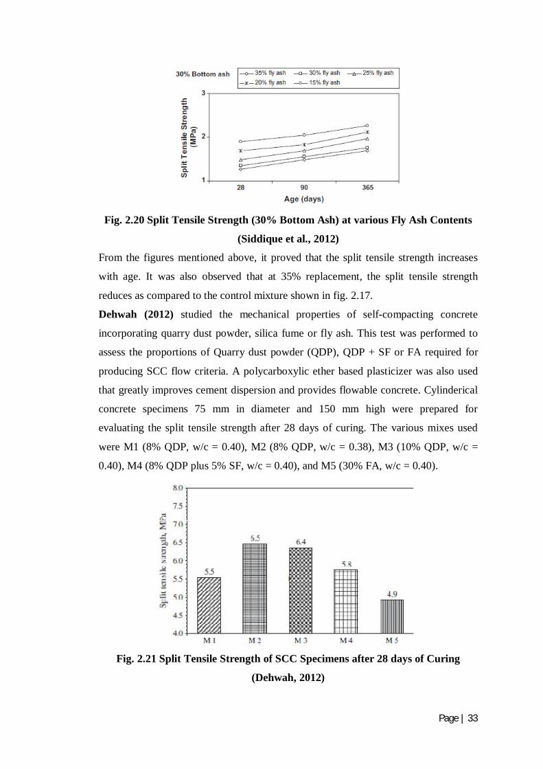
2.20 Split tensile strength (30% bottom ash) at various fly ash contents (Siddique et al., 2012)
33
2.21 Split tensile strength of SCC specimens after 28 days of curing (Dehwah, 2012)
33
2.22 The variation in concrete split tensile strengths with respect to fly ash ratio (Boga and Topcu, 2012)
34
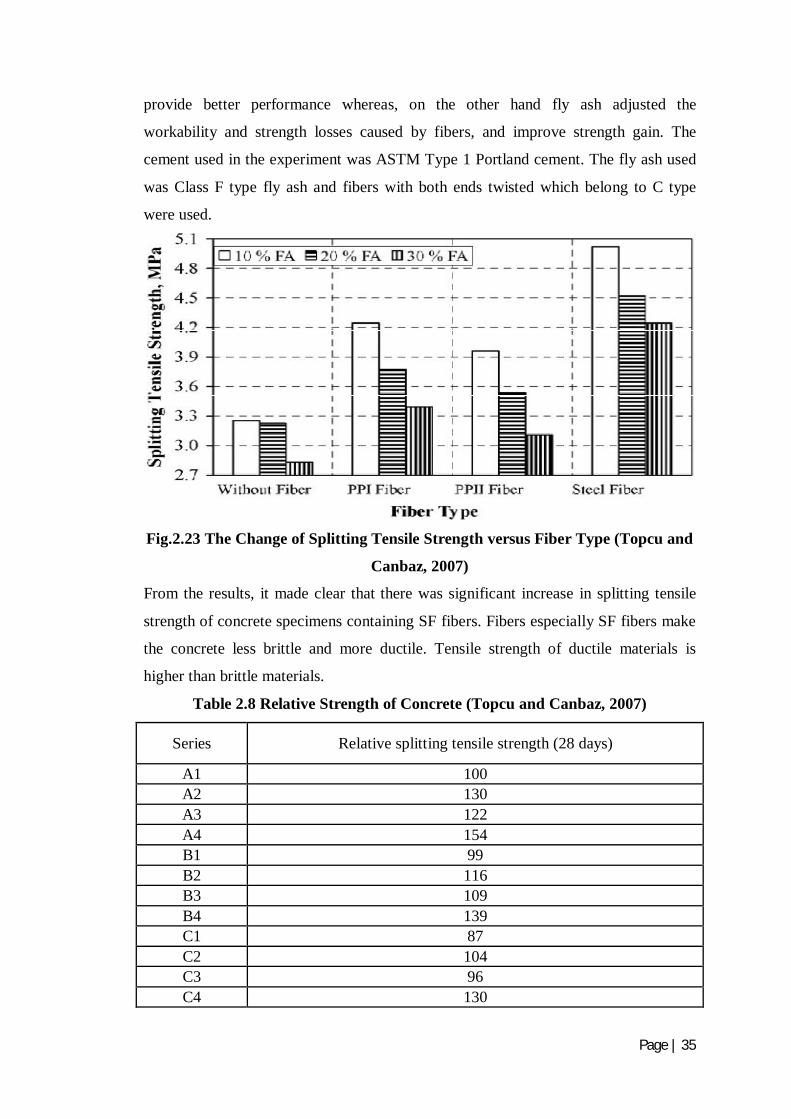
2.23 The change of split tensile strength versus fiber type (Topcu and Canbaz, 2007)
35
2.24 Split tensile strength versus age (Siddique, 2003) 36
2.25 Split tensile strength versus fly ash percentage (Siddique, 2003)
36
2.26 Tensile young’s modulus-equivalent age (Yoshitake et al., 2013)
37
2.27 Average modulus of elasticity for different MWCNTs composite specimens with the standard error of the mean (Abu Al-Rub et al., 2012)
38
2.28 Variation of the normalized Young’s modulus with the CNTs concentration for two different aspect ratios; long and short (Abu Al-Rub et al., 2012)
39
2.29 Modulus of Elasticity versus age (Siddique, 2003) 42
2.30 Modulus of Elasticity versus fly ash percentage (Siddique, 2003)
42
2.31 Chloride permeability test results of field and core concrete specimens (Nassar et al., 2013)
44
2.32 Change in total charge passed with respect to fly ash ratio (Boga and Topcu, 2012)
45
CHAPTER 3 EXPERIMENTAL PROGRAM 48 3.1 Setup for Compressive Strength 56 3.2 Setup for Split Tensile Strength 57 3.3 Setup for Young’s Modulus using Extensiometer 58

vii
3.4 Vacuum Desiccator’s Bowl 60 3.5 Setup for Rapid Chloride Permeability Test 60
CHAPTER 4 RESULTS AND DISCUSSIONS 61 4.1 Compressive strength at 7 days 62 4.2 Compressive strength at 28 days 62 4.3 Relation between compressive strength and % CNT 63
4.4 Relative compressive strength carbon nanotubes-fly ash cement composites to normal Portland cement at 28 days
63
4.5 Split tensile strength at 7 days 64
4.6 Split tensile strength at 28 days 65
4.7 Relation between split tensile strength and % CNT at 28 days
65
4.8 Relative split tensile strength carbon nanotubes-fly ash cement composites to normal Portland cement at 28 days
66
4.9 Relative Compressive strength and Split tensile strength to PC at 28 days
66
4.10 Young’s modulus at 7 days 68 4.11 Young’s modulus at 28 days 68
4.12 Relation between young’s modulus and %CNT at 28 days
69
4.13 Total charge passed in coulombs at 7 days 70 4.14 Total charge passed in coulombs at 28 days 70

viii
LIST OF TABLES
Table No. Title Page No. CHAPTER 1 INTRODUCTION 1
1.1 Requirements for fly ash and natural pozzolans for use as a mineral admixture in portland cement concrete as per ASTM C 618-93
16
CHAPTER 2 LITERATURE REVIEW 18 2.1 Concrete mix proportions (Sathawane et al., 2013) 19
2.2 Results of compressive strength with different % of FA+RHA (Sathawane et al., 2013)
19
2.3 Mix proportion (Karahan and Atis, 2011) 24
2.4 Compressive strength results (Karahan and Atis, 2011) 24
2.5 Mix proportions of carbon nanotubes-fly ash cement composites (Chaipanich et al., 2010)
27
2.6 Relative strength of concrete (Topcu and Canbaz, 2007) 30
2.7 Results of split tensile strength with different % of FA+RHA at 28 days of curing (Sathawane et al., 2013)
31
2.8 Relative strength of concrete (Topcu and Canbaz, 2007) 35
2.9 Mix proportion of concrete (Yoshitake et al., 2013) 37
2.10 Summary of obtained Young’s modulus values from the literature for CNT/cement composites (Abu Al-Rub et al., 2012)
40
2.11 Mix proportion (Karahan and Atis, 2011) 41
2.12 Young’s modulus test results (Karahan and Atis, 2011) 41
2.13 Modulus of Elasticity test results (Bouzoubaa et al., 2001) 43
2.14 ASTM 1202 limit values (Boga and Topcu, 2012) 44
2.15 Concrete mix proportion (Nath and Sarker, 2011) 46
2.16 Rapid Chloride Permeability Test results (Nath and Sarker, 2011) 46
2.17 Resistance to chloride-ion penetration (Bouzoubaa et al., 2001) 47

ix
CHAPTER 3 EXPERIMENTAL PROGRAM 48 3.1 Physical properties of Ordinary Portland cement 48
3.2 Physical properties of fine aggregates 49
3.3 Sieve analysis of fine aggregates 49
3.4 Physical properties of coarse aggregates 50
3.5 Sieve analysis of coarse aggregates 50
3.6 Physical properties of CNT 51
3.7 Mix proportion 53
3.8 Detailed descriptions of concrete mixes 53
3.9 Concrete Mixes 54
3.10 Chloride Ion Penetrability based on charge passed (ASTM 1202-97) 59
CHAPTER 4 RESULTS AND DISCUSSIONS 61 4.1 Compressive strength tested at 7 days and 28 days 61
4.2 Split tensile strength tested at 7 days and 28 days 64
4.3 Young’s modulus tested at 7 days and 28 days 67
4.4 Rapid Chloride Permeability Test at 7 days and 28 days 69
Page | 1
CHAPTER 1
INTRODUCTION
1.1 GENERAL
Concrete construction is likely to give trouble free service throughout in the design
life. However, these opportunities are not realised in many constructions because of
structural deficiency, material weakening, unexpected over loadings or physical
damage. Premature material weakening arises from number of causes, the most
common being when the constructional specifications are violated or due to the
exposure to the harsher service environment than those anticipated during the
planning and design stages. Physical damages can also arise from fire explosions etc.
Except in extreme cases, most of the structures require renovation to meet its
functional requirements by considering appropriate repair techniques.
In the present world, various types of measures are employed to repair the concrete
structures rather to build them again. These measures are retrofitting; FRP’s, etc. Also
along with these measures, nanotechnology plays a quite important role in the field of
researches. Various nanomaterials are fullerenes, quantum dots, nanowires, nonorods,
nanosilica. These are used as an additive in concrete and improve the mechanical and
durability properties of concrete. Fly ash being employed in concrete from the past
times also has a vital role in improving the strength properties of concrete. In the
earlier ages, fly ash has not much influence on strength because strength goes on
decreasing but at later ages, properties tend to increase. Hence this is also utilized in
concrete structures where strength at earlier ages is not an issue.
1.2 NANOMATERIALS
Nanomaterials are defined as materials with at least one external dimension in the size
range from approximately 1-100 nanometres. Nanoparticles that are naturally
occurring (e.g., volcanic ash, soot from forest fires) or are the incidental by-products
of combustion processes (e.g., welding, diesel engines) are usually physically and
chemically heterogeneous and often termed ultrafine particles. Engineered
nanoparticles are deliberately produced and designed with very definite properties
related to shape, size, surface properties and chemistry. These properties are reflected
in aerosols, colloids, or powders. Often, the behaviour of nanomaterials may depend
more on surface area than particle composition itself. Relative surface area is one of
the principal factors that enhance its reactivity, strength and electrical properties.

Page | 2
Engineered nanoparticles may be bought from commercial vendors or generated via
experimental procedures by researchers in the laboratory (e.g., CNTs can be produced
by laser ablation, HiPCO (high-pressure carbon monoxide, arc discharge, and
chemical vapor deposition (CVD)). Examples of engineered nanomaterials include:
carbon buckeyballs or fullerenes; carbon nanotubes; metal or metal oxide
nanoparticles (e.g., gold, titanium dioxide); quantum dots, nano silica, titanium
dioxide, nano clay, cerium dioxide, etc.
1.3 CARBON NANOTUBES
Carbon nanotubes (CNTs) are allotropes of carbon with a cylindrical nanostructure.
Nanotubes have been constructed with length-to-diameter ratio of up to
132,000,000:1, significantly larger than for any other material. These
cylindrical carbon molecules have unusual properties, which are valuable for
nanotechnology, electronics, optics and other fields of materials science and
technology. In addition to their thermal conductivity, mechanical
and electrical properties, carbon nanotubes are also found useful in other fields like as
they can be used as additives to various structural materials. For instance, nanotubes
form a tiny portion of the material(s) in some (primarily carbon fibre) baseball bats,
golf clubs, or car parts.
Nanotubes are members of the fullerene structural family. Their name is derived from
their long, hollow structure with the walls formed by one-atom-thick sheets of carbon,
called graphene. These sheets are rolled at specific and discrete ("chiral") angles, and
the combination of the rolling angle and radius decides the nanotube properties; for
example, whether the individual nanotube shell is a metal or semiconductor.
Nanotubes are categorized as single-walled nanotubes (SWNTs) and multi-walled
nanotubes (MWNTs). Individual nanotubes naturally align themselves into "ropes"
held together by van der Waals forces, more specifically, pi-stacking.
Applied quantum chemistry, specifically, orbital hybridization best describes
chemical bonding in nanotubes. The chemical bonding of nanotubes is composed
entirely of sp2 bonds, similar to those of graphite. These bonds, which are stronger
than the sp3 bonds found in alkanes and diamond, provide nanotubes with their unique
strength.
1.4 HISTORY OF CARBON NANOTUBES
Carbon nanotubes with nanoscale dimension (1-D) have been well-known over the
past 15 years. In the 1950s, there was an initial discovery of first carbon nanotubes by

Page | 3
Roger Bacon. He was credited with the first visual impression of the tubes of atoms
that roll up and are capped with fullerene molecules by many scientists in the field.
Fig. 1.1 First observation of Carbon nanotubes by Roger bacon
But at this early stage, nobody believed that whether his discovery could impact
scientific research or not.
In 1952 L. V. Radushkevich and V. M. Lukyanovich published clear images of 50 nm
diameter tubes made of carbon in the Soviet Journal of Physical Chemistry, but the
main problem arises that the article was published in Russian language. It was likely
that carbon nanotubes were produced before this date, but the discovery of
the transmission electron microscope (TEM) allowed direct visualization of these
structures.
Oberlin, Endo and Koyama published a paper in 1976 clearly showed hollow carbon
fibers with nanometer-scale diameters by the use of vapour-growth
technique. Additionally, the authors showed a TEM image of a nanotube consisting of
a single wall of graphene. Later, Endo has referred to this image as a single-walled
nanotube.
In 1979, John Abrahamson showed evidence of carbon nanotubes at the 14th Biennial
Conference of Carbon at Pennsylvania State University. The conference paper
described carbon nanotubes as carbon fibers that were produced on carbon anodes
during arc discharge. A characterization of these fibers was given as well as
hypotheses for their growth in a nitrogen atmosphere at low pressures.
In 1981, a group of Soviet scientists published the results of chemical and structural
characterization of carbon nanoparticles produced by a thermocatalytical

Page | 4
disproportionation of carbon monoxide. Using TEM images and XRD patterns, the
authors suggested that their “carbon multi-layer tubular crystals” were formed by
rolling graphene layers into cylinders. They speculated that by rolling graphene layers
into a cylinder, many different arrangements of graphene hexagonal nets were
possible. They suggested two possibilities of such arrangements: circular arrangement
(armchair nanotube) and a spiral, helical arrangement (chiral tube).
In 1987, Howard G. Tennett of Hyperion Catalysis was issued a U.S. patent for the
production of “cylindrical discrete carbon fibrils” with a “constant diameter between
about 3.5 and about 70 nanometers, length 102 times the diameter, and an outer region
of multiple essentially continuous layers of ordered carbon atoms and a distinct inner
core’’
In 1991, Iijima's discovered multi-walled carbon nanotubes in the insoluble material
of arc-burned graphite rods. On the other hand, Mintmire, Dunlap, White's predicted
that if single-walled carbon nanotubes could be made, then they would demonstrate
remarkable conducting properties.
In 1991, Iijima during his study on the synthesis of fullerenes by using electric arc
discharge technique discovered multi-walled carbon nanotubes (MWNTs), like as
Russian dolls, containing at least two graphene layers, and generally have inner
diameters of approximately 4 nm. Two years later, Iijima and Ichihashi of NEC and
Bethune and colleagues of the IBM Almaden Research Center in California
synthesized single-walled carbon nanotubes (SWNTs). The SWNTs were synthesized
by the same procedure of producing MWNTs but by adding transition-metal catalysts
to the carbon. The arc discharge technique was well-known to produce the famed
Buckminster fullerene on a preparative scale, and these results appeared to extend the
run of accidental discoveries relating to fullerenes. The appearance of SWNT’s
comparable to that of MWCNTs was quite different. The individual tubes have very
small diameters (typically ~ 1nm), and are curled and looped rather than straight. In
the early 1990s, two research groups examined electronic properties of individual
SWNTs. Many believe that Iijima's report in 1991 was of particular importance
because it brought carbon nanotubes into the awareness of the scientific community as
a whole.
Page | 5
1.5 TYPES OF NANOTUBES
1.5.1 Single Walled Carbon Nanotube
Single-walled nanotubes (SWNT) have a diameter of close to 1 nanometer, with a
tube length that can be many millions of times longer. The structure of a SWNT can
be conceptualized by wrapping a one-atom-thick layer of graphite called graphene
into a seamless cylinder.
1.5.2 Multi Walled Carbon Nanotube
Multi-walled nanotubes (MWNT) consist of multiple rolled layers (concentric tubes)
of graphene. There are two models that can be used to describe the structures of multi-
walled nanotubes. In the Russian Doll model, sheets of graphite are arranged in
concentric cylinders. In the Parchment model, a single sheet of graphite is rolled in
around itself, resembling a scroll of parchment or a rolled newspaper. The interlayer
distance in multi-walled nanotubes is close to the distance between graphene layers in
graphite, approximately 3.4 Å. The Russian Doll structure is observed more
commonly. Its individual shells can be described as SWNTs, which can be metallic or
semiconducting. Because of statistical probability and restrictions on the relative
diameters of the individual tubes, one of the shells, and thus the whole MWNT, is
usually a zero-gap metal.
Double-walled carbon nanotubes (DWNT) form a special class of nanotubes because
their morphology and properties are similar to those of SWNT but their resistance to
chemicals is significantly improved. This is especially important when grafting of
chemical functions at the surface of the nanotubes is required to add new properties to
the CNT. In the case of SWNT, covalent functionalization will break some
C=C double bonds, leaving "holes" in the structure on the nanotube and, thus,
modifying both its mechanical and electrical properties. In the case of DWNT, only
the outer wall is modified. DWNT synthesis on the gram-scale was first proposed in
2003 by the CCVD technique, from the selective reduction of oxide solutions in
methane and hydrogen.
1.5.3 Torus
A nanotorus is a carbon nanotube bent into a torus (doughnut shape). Nanotori are
predicted to have many unique properties, such as magnetic moments 1000 times
larger than previously expected for certain specific radii. Properties such as magnetic
moment, thermal stability, etc. vary widely depending on radius of the torus and
radius of the tube.

Page | 6
1.5.4 Nanobud
Carbon nanobuds are a newly created material combining two previously discovered
allotropes of carbon: carbon nanotubes and fullerenes. In this new material, fullerene-
like "buds" are covalently bonded to the outer sidewalls of the underlying carbon
nanotube. This hybrid material has useful properties of both fullerenes and carbon
nanotubes. In particular, they have been found to be exceptionally good field emitters.
In composite materials, the attached fullerene molecules may function as molecular
anchors preventing slipping of the nanotubes, thus improving the composite’s
mechanical properties.
1.5.5 Graphenated Carbon Nanotubes (g-CNTs)
Graphenated CNTs are a relatively new hybrid that combines graphitic foliates grown
along the sidewalls of multiwalled CNTs. Yu et al. reported on "chemically bonded
graphene leaves" growing along the sidewalls of CNTs. Stoner et al. described these
structures as "graphenated CNTs" and reported in their use for enhanced super
capacitor performance. Hsu et al. further reported on similar structures formed on
carbon fibre paper, also for use in super capacitor applications. The foliate density can
vary as a function of deposition conditions (e.g. temperature and time) with their
structure ranging from few layers of graphene (< 10) to thicker, more graphite-like.
The fundamental advantage of an integrated graphene-CNT structure is the high
surface area three-dimensional framework of the CNTs coupled with the high edge
density of graphene. Graphene edges provide significantly higher charge density and
reactivity than the basal plane, but they are difficult to arrange in three-dimensional,
high volume-density geometry. CNTs are readily aligned in high density geometry
(i.e., a vertically aligned forest) but lack high charge density surfaces—the sidewalls
of the CNTs are similar to the basal plane of graphene and exhibit low charge density
except where edge defects exist. Depositing a high density of graphene foliates along
the length of aligned CNTs can significantly increase the total charge capacity per
unit of nominal area as compared to other carbon nanostructures.
1.5.6 Nitrogen Doped Carbon Nanotubes
Nitrogen doped carbon nanotubes (N-CNTs), can be produced through 5 main
methods, Chemical Vapour Deposition, high-temperature and high-pressure reactions,
gas-solid reaction of amorphous carbon with NH3 at high temperature, solid
reaction, and solvo thermal synthesis.

Page | 7
N-CNTs can also be prepared by a CVD method of pyrolysizing melamine under Ar
at elevated temperatures of 800oC - 980oC. However synthesis via CVD and
melamine results in the formation of bamboo structured CNTs. XPS spectra of grown
N-CNTs reveals nitrogen in five main components, pyridinic nitrogen, pyrrolic
nitrogen, quaternary nitrogen, and nitrogen oxides. Furthermore synthesis temperature
affects the type of nitrogen configuration.
Nitrogen doping plays a pivotal role in Lithium storage. N-doping provides defects in
the walls of CNTs allowing for Li ions to diffuse into interwall space. It also increases
capacity by providing more favourable bind of N-doped sites. N-CNTs are also much
more reactive to metal oxide nanoparticle deposition which can further enhance
storage capacity, especially in anode materials for Li-ion
batteries. However Boron doped nanotubes has been shown to make batteries with
triple capacity. 1.5.7 Peapod
A Carbon peapod is a novel hybrid carbon material which traps fullerene inside a
carbon nanotube. It can possess interesting magnetic properties with heating and
irradiating. It can also be applied as an oscillator during theoretical investigations and
predictions.
1.5.8 Cup-Stacked Carbon Nanotubes
Cup-stacked carbon nanotubes (CSCNTs) differ from other quasi-1D carbon
structures, which normally behave as quasi-metallic conductors of electrons. CSCNTs
exhibit semiconducting behaviours due to the stacking microstructure of graphene
layers.
1.5.9 Extreme Carbon Nanotubes
The observation of the longest carbon nanotubes (18.5 cm long) was reported in 2009.
These nanotubes were grown on Si substrates using an improved chemical vapour
deposition (CVD) method and represent electrically uniform arrays of single-walled
carbon nanotubes.
The shortest carbon nanotube is an organic compound cycloparaphenylene, which
was synthesized in early 2009.
The thinnest carbon nanotube is armchair (2, 2) CNT with a diameter of 3 Å. This
nanotube was grown inside a multi-walled carbon nanotube. Assigning of carbon
nanotube type was done by combination of high-resolution transmission electron
Page | 8
microscopy (HRTEM), Raman spectroscopy and density functional theory (DFT)
calculations.
The thinnest freestanding single-walled carbon nanotube is about 4.3 Å in diameter.
Researchers suggested that it can be either (5, 1) or (4, 2) SWCNT, but exact type of
carbon nanotube remains questionable. (3, 3), (4, 3) and (5, 1) carbon nanotubes (all
about 4 Å in diameter) were unambiguously identified using aberration-
corrected high-resolution transmission electron microscopy inside double-walled
CNTs.
The highest density of CNTs was achieved in 2013, grown on a conductive titanium-
coated copper surface that was coated with co-catalysts cobalt and molybdenum at
lower than typical temperatures of 450 °C. The tubes averaged a height of 0.38 μm
and a mass density of 1.6 g cm-3. The material showed ohmic conductivity (lowest
resistance ∼22 kΩ).
1.6 PROPERTIES OF CARBON NANOTUBES
1.6.1 Strength
Carbon nanotubes are proved to be the strongest and stiffest materials due to the
covalent sp2 bonds formed between the individual carbon atoms. Due to this type of
bonding, the strength results are more favourable in terms of tensile strength and
elastic modulus. In 2000, a test was conducted on multi-walled carbon nanotube for
tensile properties and the test was succeeded to have strength of 63 GPa and in 2008,
tests revealed that individual CNT shells have strengths of up to 100 GPa, which is in
agreement with quantum/atomistic models. As individual CNT shells possess
extremely high strength, weak shear interactions between adjacent shells and tubes
lowers the strength of multi-walled carbon nanotubes and carbon nanotube bundles
only to few GPa’s. This limitation has been recently addressed by applying high-
energy electron irradiation, which crosslinks inner shells and tubes, and successfully
increases the strength of these materials to 60 GPa for multi-walled carbon nanotubes
and 17 GPa for double-walled carbon nanotube bundles.
1.6.2 Kinetic Properties
Multi-walled nanotubes are individual nanotubes shells placed concentrically within
one another. These reveal a striking telescoping property whereby an inner nanotube
core may slide, almost without friction, within its outer nanotube shell, thus
possessing an atomically perfect linear or rotational bearing. The precise positioning
of atoms of carbon to create useful machines is one of the true examples in molecular
Page | 9
nanotechnology. Already, this property has been utilized to create the world's smallest
rotational motor. Future applications such as a gigahertz mechanical oscillator are also
envisaged.
1.6.3 Electrical Properties
The unique electrical properties of carbon nanotubes are to a large extent derived
from their 1-D character and the peculiar electronic structure of graphite. They have
extremely low electrical resistance. Resistance occurs when an electron collides with
some defect in the crystal structure of the material though which it is passing. The
defect could be an impurity atom, a defect in the crystalline structure, or an atom
vibrating about its position in the crystal. Such collisions deflect the electron from its
path but the electrons inside a carbon nanotube are not so easily scattered because of
their small diameter and huge ratio of length to diameter ratio that can be up in the
millions or even higher. 1.6.4 Thermal Properties
CNT have now been shown to have thermal conductivity at least twice that of
diamond. CNT have the unique property of feeling cold to the touch, like metal, on
the sides with the tube ends exposed, but similar to wood on the other sides. The
specific heat and thermal conductivity of carbon nanotubes systems are determined
primarily by phonons. The measurements of the thermoelectric power (TEP) of
nanotubes systems give direct information for the type of carriers and conductivity
mechanisms.
1.6.5 Mechanical Properties
The carbon nanotubes are expected to have high stiffness and axial strength as a result
of carbon-carbon sp2 bonding. The practical application of the nanotubes requires the
study of the elastic response, the inelastic behaviour and buckling, yield strength and
fracture. Nanotubes are the stiffest known fibre, with a measured Young’s modulus of
1.4 TPa and elongation to failure of 20–30%, which projects to a tensile strength of
well above 100 GPa (possibly higher), by far the highest known. For comparison, the
Young’s modulus of high-strength steel is around 200 GPa, and its tensile strength is
1–2 GPa.
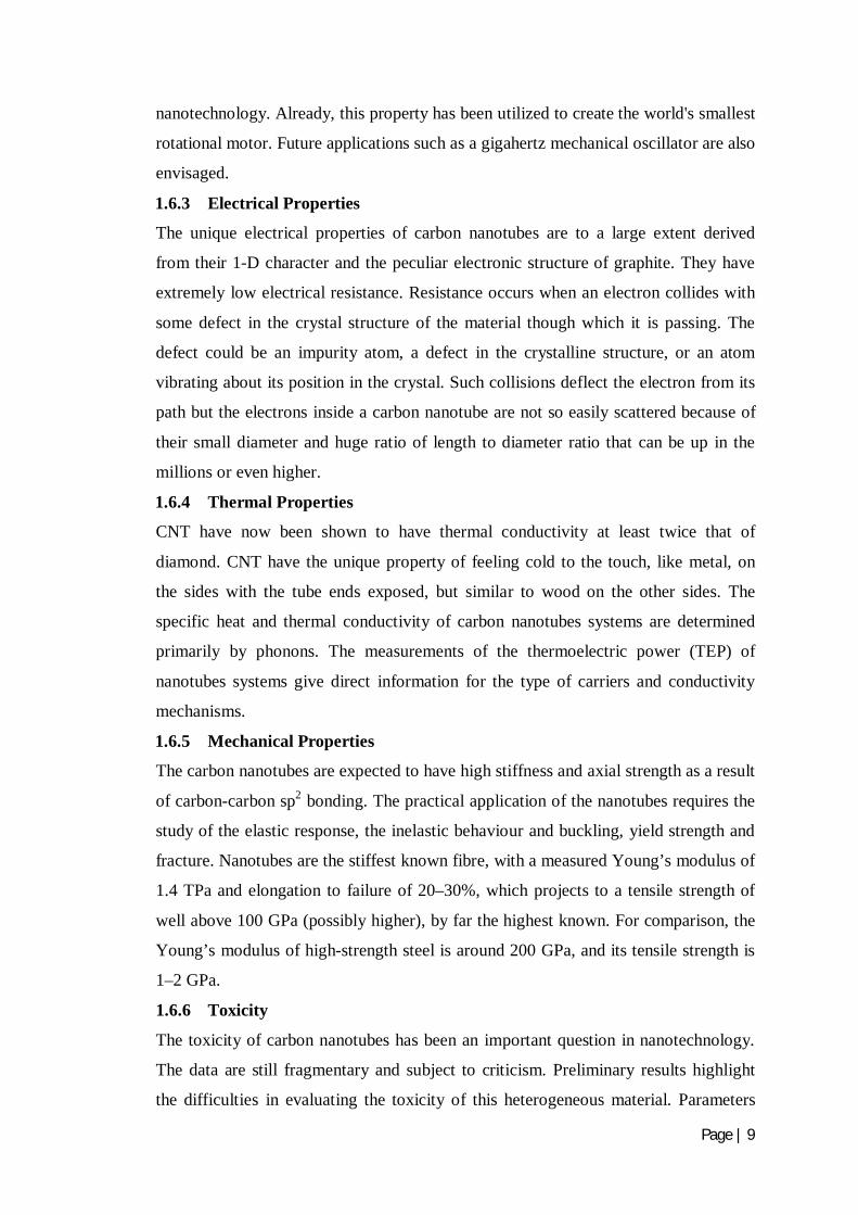
1.6.6 Toxicity
The toxicity of carbon nanotubes has been an important question in nanotechnology.
The data are still fragmentary and subject to criticism. Preliminary results highlight
the difficulties in evaluating the toxicity of this heterogeneous material. Parameters
Page | 10
such as structure, size distribution, surface area, surface chemistry, surface charge,
and agglomeration state as well as purity of the samples, have considerable impact on
the reactivity of carbon nanotubes. However, available data clearly show that, under
some conditions, nanotubes can cross membrane barriers, which suggests that, if raw
materials reach the organs, they can induce harmful effects such as inflammatory and
fibrotic reactions. Under certain conditions CNTs can enter human cells and
accumulate in the cytoplasm, can cause cell death. Results of rodent studies
collectively show that regardless of the process by which CNTs were synthesized and
the types and amounts of metals they contained, CNTs were capable of producing
inflammation, epithelioid granulomas (microscopic nodules), fibrosis and
biochemical/toxicological changes in the lungs. Comparative toxicity studies in which
mice were given equal weights of test materials showed that SWCNTs were more
toxic than quartz, which is considered a serious occupational health hazard when
chronically inhaled. The needle-like fibre shape of CNTs is similar to asbestos fibres.
This raises the idea that widespread use of carbon nanotubes may lead to pleural
mesothelioma, a cancer of the lining of the lungs orperitoneal mesothelioma, a cancer
of the lining of the abdomen.
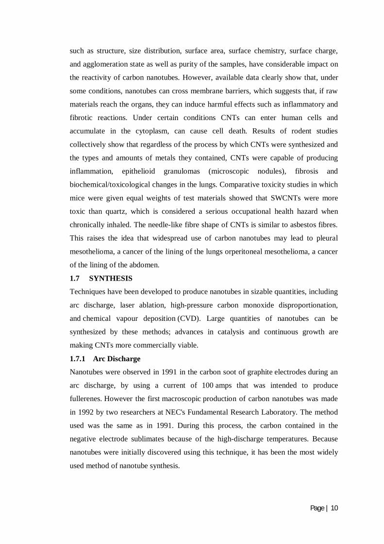
1.7 SYNTHESIS
Techniques have been developed to produce nanotubes in sizable quantities, including
arc discharge, laser ablation, high-pressure carbon monoxide disproportionation,
and chemical vapour deposition (CVD). Large quantities of nanotubes can be
synthesized by these methods; advances in catalysis and continuous growth are
making CNTs more commercially viable.
1.7.1 Arc Discharge
Nanotubes were observed in 1991 in the carbon soot of graphite electrodes during an
arc discharge, by using a current of 100 amps that was intended to produce
fullerenes. However the first macroscopic production of carbon nanotubes was made
in 1992 by two researchers at NEC's Fundamental Research Laboratory. The method
used was the same as in 1991. During this process, the carbon contained in the
negative electrode sublimates because of the high-discharge temperatures. Because
nanotubes were initially discovered using this technique, it has been the most widely
used method of nanotube synthesis.
Page | 11
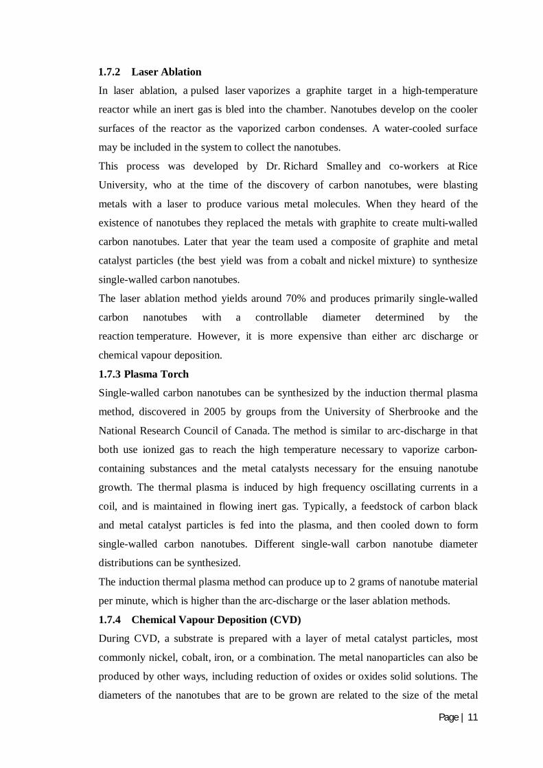
1.7.2 Laser Ablation
In laser ablation, a pulsed laser vaporizes a graphite target in a high-temperature
reactor while an inert gas is bled into the chamber. Nanotubes develop on the cooler
surfaces of the reactor as the vaporized carbon condenses. A water-cooled surface
may be included in the system to collect the nanotubes.
This process was developed by Dr. Richard Smalley and co-workers at Rice
University, who at the time of the discovery of carbon nanotubes, were blasting
metals with a laser to produce various metal molecules. When they heard of the
existence of nanotubes they replaced the metals with graphite to create multi-walled
carbon nanotubes. Later that year the team used a composite of graphite and metal
catalyst particles (the best yield was from a cobalt and nickel mixture) to synthesize
single-walled carbon nanotubes.
The laser ablation method yields around 70% and produces primarily single-walled
carbon nanotubes with a controllable diameter determined by the
reaction temperature. However, it is more expensive than either arc discharge or
chemical vapour deposition. 1.7.3 Plasma Torch
Single-walled carbon nanotubes can be synthesized by the induction thermal plasma
method, discovered in 2005 by groups from the University of Sherbrooke and the
National Research Council of Canada. The method is similar to arc-discharge in that
both use ionized gas to reach the high temperature necessary to vaporize carbon-
containing substances and the metal catalysts necessary for the ensuing nanotube
growth. The thermal plasma is induced by high frequency oscillating currents in a
coil, and is maintained in flowing inert gas. Typically, a feedstock of carbon black
and metal catalyst particles is fed into the plasma, and then cooled down to form
single-walled carbon nanotubes. Different single-wall carbon nanotube diameter
distributions can be synthesized.
The induction thermal plasma method can produce up to 2 grams of nanotube material
per minute, which is higher than the arc-discharge or the laser ablation methods.
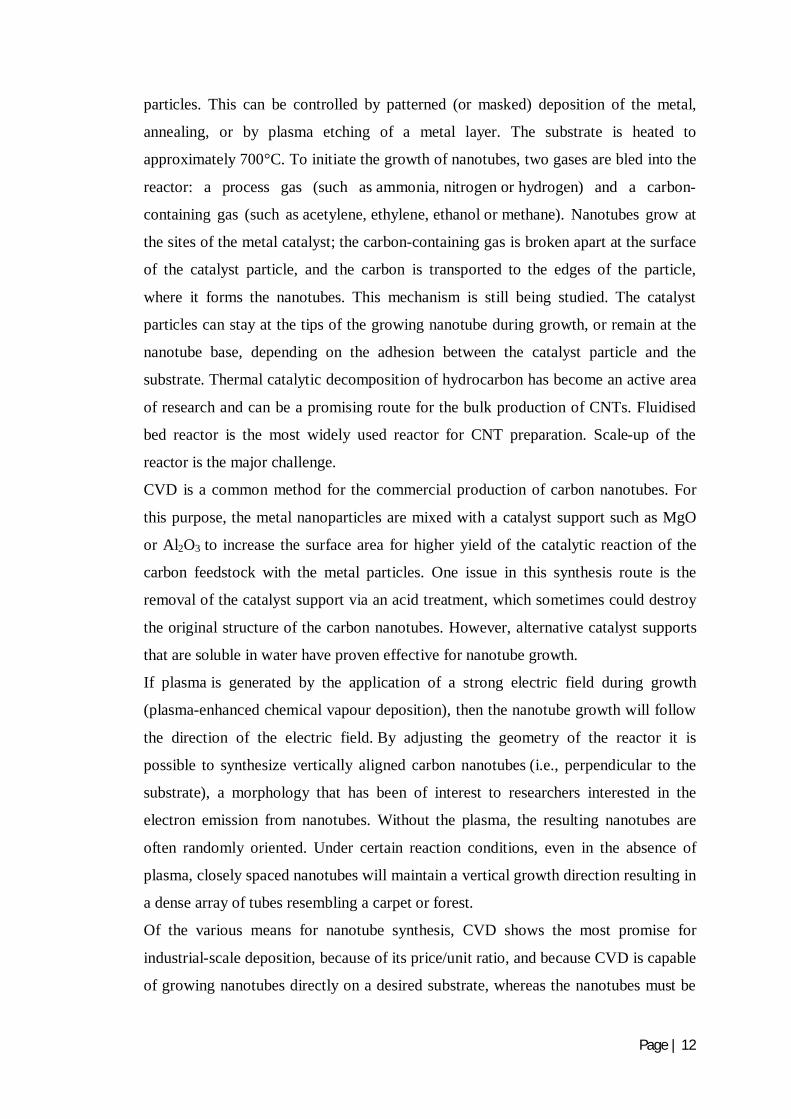
1.7.4 Chemical Vapour Deposition (CVD)
During CVD, a substrate is prepared with a layer of metal catalyst particles, most
commonly nickel, cobalt, iron, or a combination. The metal nanoparticles can also be
produced by other ways, including reduction of oxides or oxides solid solutions. The
diameters of the nanotubes that are to be grown are related to the size of the metal
Page | 12
particles. This can be controlled by patterned (or masked) deposition of the metal,
annealing, or by plasma etching of a metal layer. The substrate is heated to
approximately 700°C. To initiate the growth of nanotubes, two gases are bled into the
reactor: a process gas (such as ammonia, nitrogen or hydrogen) and a carbon-
containing gas (such as acetylene, ethylene, ethanol or methane). Nanotubes grow at
the sites of the metal catalyst; the carbon-containing gas is broken apart at the surface
of the catalyst particle, and the carbon is transported to the edges of the particle,
where it forms the nanotubes. This mechanism is still being studied. The catalyst
particles can stay at the tips of the growing nanotube during growth, or remain at the
nanotube base, depending on the adhesion between the catalyst particle and the
substrate. Thermal catalytic decomposition of hydrocarbon has become an active area
of research and can be a promising route for the bulk production of CNTs. Fluidised
bed reactor is the most widely used reactor for CNT preparation. Scale-up of the
reactor is the major challenge.
CVD is a common method for the commercial production of carbon nanotubes. For
this purpose, the metal nanoparticles are mixed with a catalyst support such as MgO
or Al2O3 to increase the surface area for higher yield of the catalytic reaction of the
carbon feedstock with the metal particles. One issue in this synthesis route is the
removal of the catalyst support via an acid treatment, which sometimes could destroy
the original structure of the carbon nanotubes. However, alternative catalyst supports
that are soluble in water have proven effective for nanotube growth.
If plasma is generated by the application of a strong electric field during growth
(plasma-enhanced chemical vapour deposition), then the nanotube growth will follow
the direction of the electric field. By adjusting the geometry of the reactor it is
possible to synthesize vertically aligned carbon nanotubes (i.e., perpendicular to the
substrate), a morphology that has been of interest to researchers interested in the
electron emission from nanotubes. Without the plasma, the resulting nanotubes are
often randomly oriented. Under certain reaction conditions, even in the absence of
plasma, closely spaced nanotubes will maintain a vertical growth direction resulting in
a dense array of tubes resembling a carpet or forest.
Of the various means for nanotube synthesis, CVD shows the most promise for
industrial-scale deposition, because of its price/unit ratio, and because CVD is capable
of growing nanotubes directly on a desired substrate, whereas the nanotubes must be
Page | 13
collected in the other growth techniques. The growth sites are controllable by careful
deposition of the catalyst.
1.8 APPLICATIONS OF CARBON NANOTUBES
Carbon nanotubes (CNTs) are extensively used in various sectors like Energy,
Medicine, Environment, Electronics and Civil Engineering applications.
A team of researchers at Rice University have developed electrodes made from
carbon nanotubes grown on graphene with very high surface area and very low
electrical resistance. They have also built a solar cell that uses graphene as
electrode while using buckyballs and carbon nanotubes to absorb light and
generate electrons.
Carbon nanotubes can also perform as a catalyst in a fuel cell by avoiding the use
of expensive platinum on which most catalysts are based.
Nanotubes and gold nanoparticles are used in sensors to detect proteins that
indicate the presence of oral cancer. Also it can be used in improving the healing
process for broken bones by providing a carbon nanotube scaffold that new bone
material can grow around, using nanotubes as a cellular scale needle to deliver
quantum dots and proteins into cancer cells.
As CNTs have high strength and flexibility, so their use also exist in aircraft
industry which includes highly stressed components, a lightweight, low power
anti-icing system.
Cables made from carbon nanotubes are strong enough to be used in building the
Space Elevator to drastically reduce the cost of lifting people and materials into
orbit.
CNTs also have tremendous range of applications in concrete structures
depending on the size and morphology of the fibrous carbons. As the size of CNT
particles is finer than cement particles, so these can be used in concrete as void
filler. On the other hand, we could say carbon nanotubes/nanofibres (CNTs/CNFs)
are used as nano-reinforcements in cement-based materials.
For load-bearing applications, CNT powders mixed with polymers or precursor
resins can increase stiffness, strength, and toughness. These enhancements depend
on CNT diameter, aspect ratio, alignment, dispersion, and interfacial interaction
with the matrix.
Page | 14
CNTs are also applicable to be used as additives in the organic precursors used to
form carbon fibres which have been used as reinforcements in high strength, light
weight, high performance composites. Theoretical studies have suggested that
SWNTs could have a Young’s modulus as high as 1TPa, which is basically the in-
plane value of defect free graphite.
Apart from strength characteristics nanotubes have shown promise in enhancing
the mechanical performance, the resistance to chloride penetration, and the self-
compacting properties of concrete and in reducing permeability and shrinkage.
The most important application of nanotubes based on their mechanical properties
will be as reinforcements in composite materials.
Makar et al. were among the first to indicate, using hardness measurements, that
CNTs can affect early-age hydration and that a strong bond is possible between
the cement paste and the CNTs. The main problem is in creating a good interface
between nanotubes and the polymer matrix and attaining good load transfer from
the matrix to the nanotubes, during loading. The reason for this is essentially
twofold. First, nanotubes are atomically smooth and have nearly the same
diameters and aspect ratios (length/diameter) as polymer chains. Second,
nanotubes are almost always organized into aggregates which behave differently
in response to a load, as compared to individual nanotubes.
The small and uniform dimensions of the nanotubes produce some interesting
applications. With extremely small sizes, high conductivity, high mechanical
strength and flexibility (ability to easily bend elastically), nanotubes may
ultimately become necessary in their use as nanoprobes.
Nowadays, researches have been carried out in using nanotubes as sensors
embedded in the concrete structures as crack detectors.
It has a wide range of scope in health monitoring applications of concrete
structures as well. Apart from these applications the major challenges that are being
faced in its usage are their availability and cost. For bulk applications, such as fillers
in composites, where the atomic structure has a much smaller impact on the resulting
properties, the quantities of nanotubes that can be manufactured still falls far short of
what industry would need. The market price of nanotubes is also too high presently
for any realistic commercial application. But it should be noted that the starting prices
for carbon fibres and fullerenes were also prohibitively high during their initial stages

Page | 15
of development, but have come down significantly in time. If CNTs are made easily
available in the market then they are prove to be the most innovative and
advantageous material in relation to concrete structures.
1.9 FLY ASH
Fly ash is one of the most extensively used by-product material in the construction
field resembling Portland cement (Pfeifer, 1969). It is an inorganic, non combustible,
finely divided residue collected or precipitated from the exhaust gases of any
industrial furnace (Halstead, 1986). Most of the fly ash particles are solid spheres and
some particles called cenospheres are hollow (Kosmatka et al., 2002). Also present
are plerospheres which are spheres containing smaller spheres inside. The particle size
in fly ash varies from less than 1µm to more than 100µm with the typical particle size
measuring less than 20µm. Their surface area is typically 300 to 500 m2/kg, although
some fly ashes can have surface areas as low as 200 m2/kg and as high as 700 m2/kg.
Fly ash is primarily silicate glass containing silica, alumina, iron and calcium. The
relative density or specific gravity of fly ash generally ranges between 1.9 and 2.8 and
the colour is generally gray or tans (Halstead, 1986).
1.9.1 Classification of Fly Ash
ASTM- C 618-93 categorizes natural pozzolans and fly ashes into the following three
categories:-
1. Class N Fly Ash: Raw or calcined natural pozzolans such as diatomaceous
earths, opaline chert and shale, stuffs, volcanic ashes and pumice come in this
category. Calcined kaolin clay and laterite shale also fall in this category of
pozzolans.
2. Class F Fly Ash: Fly ash normally produced from burning anthracite or
bituminous coal falls in this category. This class of fly ash exhibits pozzolanic
property but rarely if any, self hardening property.
3. Class C Fly Ash: Fly ash normally produced from lignite or sub-bituminous
coal is the only material included in this category. This class of fly ash has both
pozzolanic and varying degree of self cementitious properties. (Most Class C fly ash
ashes contain more than 15% CaO. But some Class C fly ashes may contain as little
as 10% CaO).
Page | 16
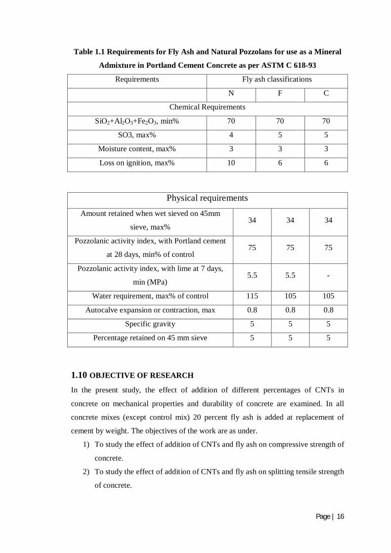
Table 1.1 Requirements for Fly Ash and Natural Pozzolans for use as a Mineral
Admixture in Portland Cement Concrete as per ASTM C 618-93
Requirements Fly ash classifications
N F C
Chemical Requirements
SiO2+Al2O3+Fe2O3, min% 70 70 70
SO3, max% 4 5 5
Moisture content, max% 3 3 3
Loss on ignition, max% 10 6 6
Physical requirements
Amount retained when wet sieved on 45mm
sieve, max% 34 34 34
Pozzolanic activity index, with Portland cement
at 28 days, min% of control 75 75 75
Pozzolanic activity index, with lime at 7 days,
min (MPa) 5.5 5.5 -
Water requirement, max% of control 115 105 105
Autocalve expansion or contraction, max 0.8 0.8 0.8
Specific gravity 5 5 5
Percentage retained on 45 mm sieve 5 5 5
1.10 OBJECTIVE OF RESEARCH In the present study, the effect of addition of different percentages of CNTs in
concrete on mechanical properties and durability of concrete are examined. In all
concrete mixes (except control mix) 20 percent fly ash is added at replacement of
cement by weight. The objectives of the work are as under.
1) To study the effect of addition of CNTs and fly ash on compressive strength of
concrete.
2) To study the effect of addition of CNTs and fly ash on splitting tensile strength
of concrete.

Page | 17
3) To study the effect of addition of CNTs and fly ash on young’s modulus of
concrete.
4) To study the effect of addition of CNTs and fly ash on permeability of
concrete.
1.11 ORIENTATION OF THESIS The thesis report consists of five chapters:
Chapter 1- Provides introduction about Carbon nanotubes and fly ash, their properties,
synthesis, applications etc.
Chapter 2- Deals with the study of various researchers on CNTs and Fly Ash and their
effect on different mechanical as well as durability properties.
Chapter 3- Details the scheme of experimentation, materials used and variables
involved. Information about concrete mix designs is also illustrated in this chapter.
Chapter 4- Presents the results, and their analysis for the strength properties such as
compressive strength, splitting tensile strength, modulus of elasticity and durability
property such as rapid chloride permeability test.
Chapter 5- Summarizes and concludes the findings of the study. Few
recommendations for further studies are also discussed.
References are placed at the end.
1.12 SUMMARY This chapter discussed about the (i) types, properties, applications of CNTs in civil
engineering work, (ii) different synthesis methods adopted, (iii) objective of thesis
and (iv) orientation of thesis.
Page | 18
CHAPTER 2
LITERATURE REVIEW
2.1 PRELIMINARY REMARKS
Nanotechnology is a science in its growing stage. In general, all of today’s practical
nanotechnologies are those using nanosized particles in so-called nanomaterials and
nanometer-size features on integrated circuits. In the world of nanotechnology,
nanomaterials either referred to as materials with nanoscale dimensions or bulk
materials containing nanosized particles. Nanoparticles are defined as particles whose
diameter is less than 100 nm. These materials exhibit various characteristics such as
extraordinary strength or unsuspected electrical, physical or chemical properties that
are completely different from those demonstrated by the same products with larger
dimensions. The reason behind this is the increased relative surface area of minute
particles. The unique multification properties of carbon nanotubes make them
promising reinforcements to many engineering materials. CNTs occur in two forms
either as single-walled carbon nanotubes (SWCNTs) or as multi-walled carbon
nanotubes (MWCNTs). SWCNTs are composed of a single graphite sheet rolled into
a long hollow cylinder, whereas MWCNTs are formed by positioning SWCNTs
concentrically one over the other. The average diameter of an individual SWCNT is
on the order of 1 nm whereas the average diameter of an individual MWCNT is on the
order of 10 nm. Their density is less than that of steel or glass fibre and also has an
elastic modulus in the range of terapascal and yield strength of approximately 20–60
GPa, and yield strain of up to 10%.
2.2 MECHANICAL PROPERTIES 2.2.1 Compressive Strength
Sathawane et al. (2013) detailed the combine effect of rice husk ash and fly ash on
concrete by 30% cement replacement. In this test, the combine proportion started
from 30% FA and 0% RHA mix together in concrete by replacement of cement with
the gradual increase of RHA by 2.5% and simultaneously gradual decrease of FA by
2.5%. The concrete specimens were tested after 7, 14, 28, 56 and 90 days of curing as
per IS: 516-1959. Their mix proportion shown as:

Page | 19
Table 2.1 Concrete Mix Proportions (Sathawane et al., 2013)
Material Quantity Proportion
Cement 435.45 kg/m3 1
Sand 476 kg/m3 1.1
Coarse Aggregates 1242.62 kg/m3 2.85
Water 191.6 kg/m3 0.44
Slump 75-100 mm ----
Table 2.2 Results of Compressive Strength with different % of FA+RHA
(Sathawane et al., 2013)
S. no.
Mix proportion Compressive strength after no. Of days of
curing in MPa
FA by %
of cement
RA by %
of cement 7 days 14 days 28 days 56 days 90 days
1 Control mixture 35.56 39.11 45.78 48 49.78
2 30 0 32.89 33.33 39.11 42.22 44.89
3 27.5 2.5 31.11 31.33 35.11 37.33 39.56
4 25 5 31.56 32.44 40.44 43.11 45.78
5 22.5 7.5 22.67 34.67 41.78 44.89 46.67
6 20 10 22.22 26.22 33.78 35.11 37.78
7 17.5 12.5 18.22 24.89 33.78 32.00 34.67
8 15 15 17.78 24.00 28.89 30.67 33.78
Fig. 2.1 Comparison of Compressive Strength for different % of RHA and FA
(Sathawane et al., 2013)
Page | 20
Based on the above results, it was concluded that the compressive strength increases
with increase in the percentage of Fly Ash and Rice Husk Ash up to replacement
(22.5% FA and7.5%% RHA) of cement in concrete for different mix proportions.
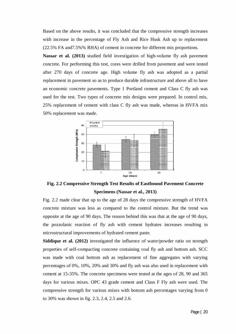
Nassar et al. (2013) studied field investigation of high-volume fly ash pavement
concrete. For performing this test, cores were drilled from pavement and were tested
after 270 days of concrete age. High volume fly ash was adopted as a partial
replacement in pavement so as to produce durable infrastructure and above all to have
an economic concrete pavements. Type 1 Portland cement and Class C fly ash was
used for the test. Two types of concrete mix designs were prepared. In control mix,
25% replacement of cement with class C fly ash was made, whereas in HVFA mix
50% replacement was made.
Fig. 2.2 Compressive Strength Test Results of Eastbound Pavement Concrete
Specimens (Nassar et al., 2013)
Fig. 2.2 made clear that up to the age of 28 days the compressive strength of HVFA
concrete mixture was less as compared to the control mixture. But the trend was
opposite at the age of 90 days. The reason behind this was that at the age of 90 days,
the pozzolanic reaction of fly ash with cement hydrates increases resulting in
microstructural improvements of hydrated cement paste.
Siddique et al. (2012) investigated the influence of water/powder ratio on strength
properties of self-compacting concrete containing coal fly ash and bottom ash. SCC
was made with coal bottom ash as replacement of fine aggregates with varying
percentages of 0%, 10%, 20% and 30% and fly ash was also used in replacement with
cement at 15-35%. The concrete specimens were tested at the ages of 28, 90 and 365
days for various mixes. OPC 43 grade cement and Class F Fly ash were used. The
compressive strength for various mixes with bottom ash percentages varying from 0
to 30% was shown in fig. 2.3, 2.4, 2.5 and 2.6.

Page | 21
Fig. 2.3 Compressive Strength (0% Bottom Ash) at Various Fly Ash Contents
(Siddique et al., 2012)
Fig. 2.4 Compressive Strength (10% Bottom Ash) at various Fly Ash Contents
(Siddique et al., 2012)
Fig. 2.5 Compressive Strength (20% Bottom Ash) at various Fly Ash Contents
(Siddique et al., 2012)
Page | 22
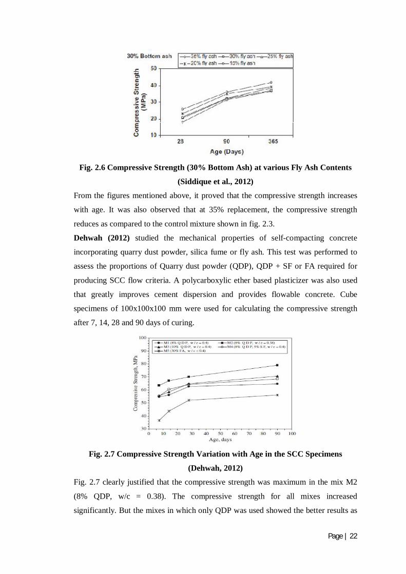
Fig. 2.6 Compressive Strength (30% Bottom Ash) at various Fly Ash Contents
(Siddique et al., 2012)
From the figures mentioned above, it proved that the compressive strength increases
with age. It was also observed that at 35% replacement, the compressive strength
reduces as compared to the control mixture shown in fig. 2.3.
Dehwah (2012) studied the mechanical properties of self-compacting concrete
incorporating quarry dust powder, silica fume or fly ash. This test was performed to
assess the proportions of Quarry dust powder (QDP), QDP + SF or FA required for
producing SCC flow criteria. A polycarboxylic ether based plasticizer was also used
that greatly improves cement dispersion and provides flowable concrete. Cube
specimens of 100x100x100 mm were used for calculating the compressive strength
after 7, 14, 28 and 90 days of curing.
Fig. 2.7 Compressive Strength Variation with Age in the SCC Specimens
(Dehwah, 2012)
Fig. 2.7 clearly justified that the compressive strength was maximum in the mix M2
(8% QDP, w/c = 0.38). The compressive strength for all mixes increased
significantly. But the mixes in which only QDP was used showed the better results as

Page | 23
compared to the mixes in which SF+QDP or FA were used. This indicated that 8-10%
QDP acted as better filler than FA or QDP+SF.
Boga and Topcu (2012) investigated the influence of fly ash on corrosion resistance
and chloride ion permeability of concrete. In this study, fly ash with varying
percentages like 0%, 15%, 30% and 45% was used in replacement to CEM 1 42.5R
cement to evaluate the compressive strength of concrete. The samples were tested for
28 and 56 days in two different conditions i.e air and water. 150x150x150 mm cube
specimens were prepared for investigating compressive strength.
Fig. 2.8 Compressive Strength with varying Fly Ash Ratios
(Boga and Topcu, 2012)
Under water curing conditions, compressive strength after 56 days showed better
results due to lengthening of cure conditions as compared to 28W. Similar is the case
for air curing conditions, due to lengthening of cure conditions, compressive strength
at 56 days showed better results as compared to 28 days because at later ages, fly ash
added reacts with Ca(OH)2 which in turn, formation of new CSH gel took place and
hence the bonding get enhanced.
Karahan and Atis (2011) investigated the durability properties of polypropylene
fiber reinforced fly ash concrete. Fly ash content used in the mix was 0%, 15%, and
30% in mass basis and fiber volume fraction was 0%, 0.05%, 0.10% and 0.20% in
volume basis. A polycarboxylic ether based plasticizer i.e. 1% of the cement content
was used.
Page | 24
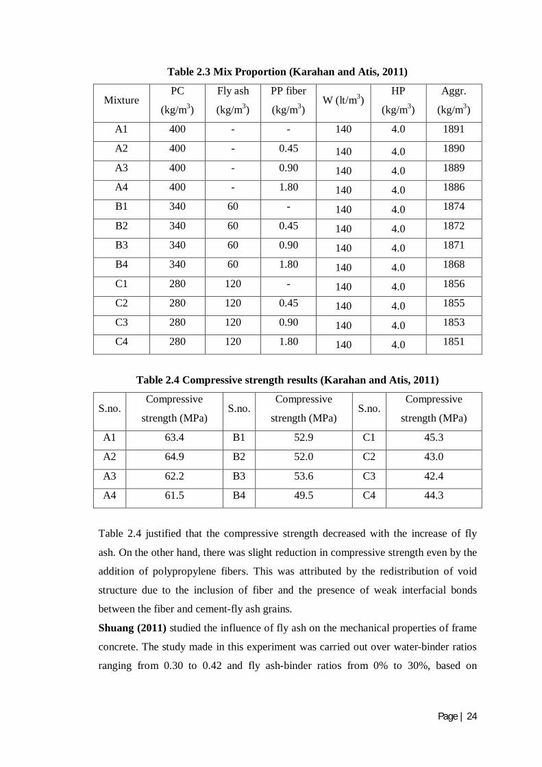
Table 2.3 Mix Proportion (Karahan and Atis, 2011)
Mixture PC
(kg/m3)
Fly ash
(kg/m3)
PP fiber
(kg/m3) W (lt/m3)
HP
(kg/m3)
Aggr.
(kg/m3)
A1 400 - - 140 4.0 1891
A2 400 - 0.45 140 4.0 1890
A3 400 - 0.90 140 4.0 1889
A4 400 - 1.80 140 4.0 1886
B1 340 60 - 140 4.0 1874
B2 340 60 0.45 140 4.0 1872
B3 340 60 0.90 140 4.0 1871
B4 340 60 1.80 140 4.0 1868
C1 280 120 - 140 4.0 1856
C2 280 120 0.45 140 4.0 1855
C3 280 120 0.90 140 4.0 1853
C4 280 120 1.80 140 4.0 1851
Table 2.4 Compressive strength results (Karahan and Atis, 2011)
S.no. Compressive
strength (MPa) S.no.
Compressive
strength (MPa) S.no.
Compressive
strength (MPa)
A1 63.4 B1 52.9 C1 45.3
A2 64.9 B2 52.0 C2 43.0
A3 62.2 B3 53.6 C3 42.4
A4 61.5 B4 49.5 C4 44.3
Table 2.4 justified that the compressive strength decreased with the increase of fly
ash. On the other hand, there was slight reduction in compressive strength even by the
addition of polypropylene fibers. This was attributed by the redistribution of void
structure due to the inclusion of fiber and the presence of weak interfacial bonds
between the fiber and cement-fly ash grains.
Shuang (2011) studied the influence of fly ash on the mechanical properties of frame
concrete. The study made in this experiment was carried out over water-binder ratios
ranging from 0.30 to 0.42 and fly ash-binder ratios from 0% to 30%, based on

Page | 25
concrete framework model theory. The compressive and flexural strengths were
determined after 28 days, 56 days and 90 days.
The results of compressive strength at different w/c ratios and with different
replacements of fly ash by weight with cement were shown in fig. 2.9, 2.10, 2.11, and
2.12 as:
Fig.2.9 Relationship between Compressive Strength and Percentage
Replacement of Fly Ash (w/cm=0.42) (Shuang, 2011)
Fig.2.10 Relationship between Compressive Strength and Percentage
Replacement of Fly Ash (w/cm=0.38) (Shuang, 2011)

Page | 26
Fig.2.11 Relationship between Compressive Strength and Percentage
Replacement of Fly Ash (w/cm=0.34) (Shuang, 2011)
Fig.2.12 Relationship between Compressive Strength and Percentage
Replacement of Fly Ash (w/cm=0.30) (Shuang, 2011)
Data from the figures above clearly showing that the 28 day compressive strength and
its corresponding mortar matrix was lower than that of control concrete and its
corresponding mortar matrix, but there was increase in strength after 56 days and 90
days. The reason behind this is as:

Page | 27
When fly ash is mixed with water, together with cement, it induces pozzolanic
reaction, in which glass phase silica (SiO2) and alumina (Al2O3) progressively react
with Ca(OH)2 formed by cement hydration, forming hydrates of calcium silicate. This
reduces the Ca(OH)2 content, which is weakness in concrete strength, while
increasing C–S–H gel, which is responsible for the formation of structure of hardened
cement. Therefore, in concrete containing fly ash, the hydration of cement forms the
hardened structure, and the pozzolanic reaction of fly ash. The reaction of SiO2 and
Al2O3 in fly ash depends on the concentration and content of Ca(OH)2 supply. The
higher the Ca(OH)2 concentration, the higher the rate of pozzolanic reaction. At the
late ages, the higher the Ca(OH)2 content, the longer that the pozzolanic reaction of
fly ash lasts.
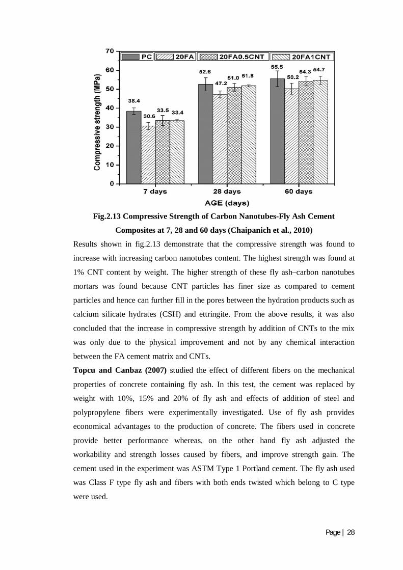
Chaipanich et al. (2010) investigated the compressive strength and microstructure of
carbon nanotubes-fly ash cement composites. In this experiment, carbon nanotubes of
0.5% and 1% by weight were added in a fly ash cement system to produce carbon
nanotubes–fly ash composites in the form of pastes and mortars. The mix proportion
of carbon nanotubes-fly ash cement composites adopted is shown in table 2.5 as:
Table 2.5 Mix Proportions of Carbon Nanotubes-Fly Ash Cement Composites
(Chaipanich et al., 2010)
Mix PC (%) FA (%) CNT (%) w/c
PC 100 - - 0.5
FA20 80 20 - 0.5
FA20:CNT0.5 80 20 0.5 0.5
FA20:CNT1 80 20 1 0.5
The ratio of water: cement blends: sand used was 0.5: 1: 3 for all mixes. The
specimens were tested after 7, 28 and 60 days and the corresponding results were
shown in fig. 2.13.
Page | 28
Fig.2.13 Compressive Strength of Carbon Nanotubes-Fly Ash Cement
Composites at 7, 28 and 60 days (Chaipanich et al., 2010)
Results shown in fig.2.13 demonstrate that the compressive strength was found to
increase with increasing carbon nanotubes content. The highest strength was found at
1% CNT content by weight. The higher strength of these fly ash–carbon nanotubes
mortars was found because CNT particles has finer size as compared to cement
particles and hence can further fill in the pores between the hydration products such as
calcium silicate hydrates (CSH) and ettringite. From the above results, it was also
concluded that the increase in compressive strength by addition of CNTs to the mix
was only due to the physical improvement and not by any chemical interaction
between the FA cement matrix and CNTs.
Topcu and Canbaz (2007) studied the effect of different fibers on the mechanical
properties of concrete containing fly ash. In this test, the cement was replaced by
weight with 10%, 15% and 20% of fly ash and effects of addition of steel and
polypropylene fibers were experimentally investigated. Use of fly ash provides
economical advantages to the production of concrete. The fibers used in concrete
provide better performance whereas, on the other hand fly ash adjusted the
workability and strength losses caused by fibers, and improve strength gain. The
cement used in the experiment was ASTM Type 1 Portland cement. The fly ash used
was Class F type fly ash and fibers with both ends twisted which belong to C type
were used.
Page | 29
Fig.2.14 Cylindrical Compressive Strength versus Fiber Type (Topcu and
Canbaz, 2007)
Fig.2.15 Cubic Compressive Strength versus Fiber Type (Topcu and Canbaz,
2007)
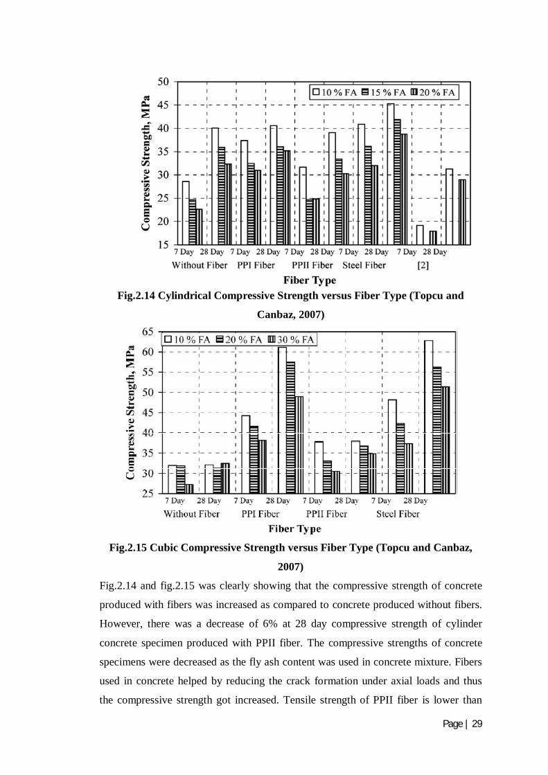
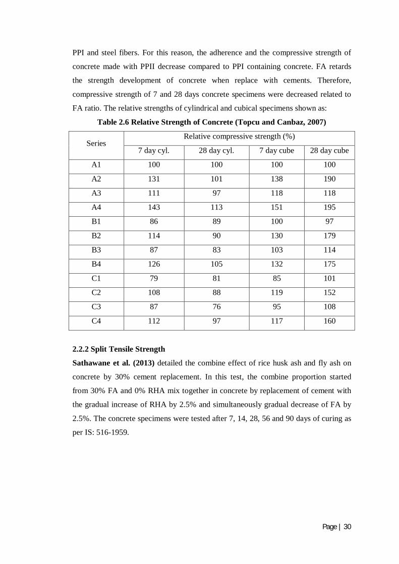
Fig.2.14 and fig.2.15 was clearly showing that the compressive strength of concrete
produced with fibers was increased as compared to concrete produced without fibers.
However, there was a decrease of 6% at 28 day compressive strength of cylinder
concrete specimen produced with PPII fiber. The compressive strengths of concrete
specimens were decreased as the fly ash content was used in concrete mixture. Fibers
used in concrete helped by reducing the crack formation under axial loads and thus
the compressive strength got increased. Tensile strength of PPII fiber is lower than
Page | 30
PPI and steel fibers. For this reason, the adherence and the compressive strength of
concrete made with PPII decrease compared to PPI containing concrete. FA retards
the strength development of concrete when replace with cements. Therefore,
compressive strength of 7 and 28 days concrete specimens were decreased related to
FA ratio. The relative strengths of cylindrical and cubical specimens shown as:
Table 2.6 Relative Strength of Concrete (Topcu and Canbaz, 2007)
Series Relative compressive strength (%)
7 day cyl. 28 day cyl. 7 day cube 28 day cube
A1 100 100 100 100
A2 131 101 138 190
A3 111 97 118 118
A4 143 113 151 195
B1 86 89 100 97
B2 114 90 130 179
B3 87 83 103 114
B4 126 105 132 175
C1 79 81 85 101
C2 108 88 119 152
C3 87 76 95 108
C4 112 97 117 160
2.2.2 Split Tensile Strength
Sathawane et al. (2013) detailed the combine effect of rice husk ash and fly ash on
concrete by 30% cement replacement. In this test, the combine proportion started
from 30% FA and 0% RHA mix together in concrete by replacement of cement with
the gradual increase of RHA by 2.5% and simultaneously gradual decrease of FA by
2.5%. The concrete specimens were tested after 7, 14, 28, 56 and 90 days of curing as
per IS: 516-1959.
Page | 31
Table 2.7 Results of Split Tensile Strength with different % Of FA+RHA at 28
days of Curing (Sathawane et al., 2013)
S.no.
Mix proportion Split tensile strength after 28
days of curing in MPa FA by % of cement RHA by % of
cement
1 Control mix 4.38
2 30 0 4.10
3 27.5 2.5 3.82
4 25 5 3.67
5 22.5 7.5 3.96
6 20 10 2.97
7 17.5 12.5 2.26
8 15 15 1.98
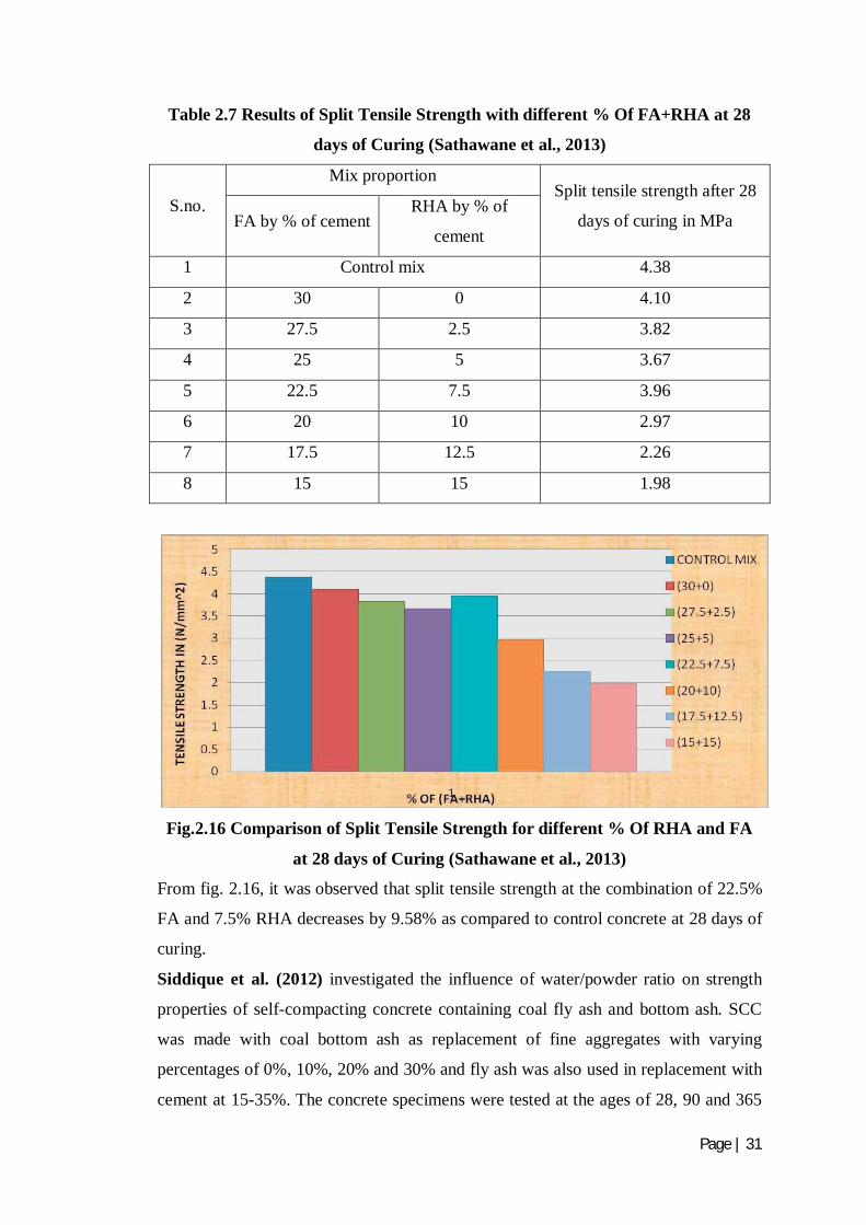
Fig.2.16 Comparison of Split Tensile Strength for different % Of RHA and FA
at 28 days of Curing (Sathawane et al., 2013)
From fig. 2.16, it was observed that split tensile strength at the combination of 22.5%
FA and 7.5% RHA decreases by 9.58% as compared to control concrete at 28 days of
curing.
Siddique et al. (2012) investigated the influence of water/powder ratio on strength
properties of self-compacting concrete containing coal fly ash and bottom ash. SCC
was made with coal bottom ash as replacement of fine aggregates with varying
percentages of 0%, 10%, 20% and 30% and fly ash was also used in replacement with
cement at 15-35%. The concrete specimens were tested at the ages of 28, 90 and 365
Page | 32
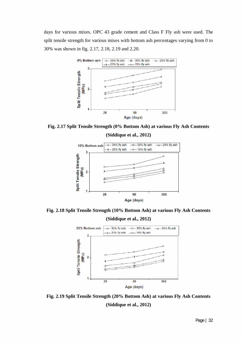
days for various mixes. OPC 43 grade cement and Class F Fly ash were used. The
split tensile strength for various mixes with bottom ash percentages varying from 0 to
30% was shown in fig. 2.17, 2.18, 2.19 and 2.20.
Fig. 2.17 Split Tensile Strength (0% Bottom Ash) at various Fly Ash Contents
(Siddique et al., 2012)
Fig. 2.18 Split Tensile Strength (10% Bottom Ash) at various Fly Ash Contents
(Siddique et al., 2012)
Fig. 2.19 Split Tensile Strength (20% Bottom Ash) at various Fly Ash Contents
(Siddique et al., 2012)
Page | 33
Fig. 2.20 Split Tensile Strength (30% Bottom Ash) at various Fly Ash Contents
(Siddique et al., 2012)
From the figures mentioned above, it proved that the split tensile strength increases
with age. It was also observed that at 35% replacement, the split tensile strength
reduces as compared to the control mixture shown in fig. 2.17.
Dehwah (2012) studied the mechanical properties of self-compacting concrete
incorporating quarry dust powder, silica fume or fly ash. This test was performed to
assess the proportions of Quarry dust powder (QDP), QDP + SF or FA required for
producing SCC flow criteria. A polycarboxylic ether based plasticizer was also used
that greatly improves cement dispersion and provides flowable concrete. Cylinderical
concrete specimens 75 mm in diameter and 150 mm high were prepared for
evaluating the split tensile strength after 28 days of curing. The various mixes used
were M1 (8% QDP, w/c = 0.40), M2 (8% QDP, w/c = 0.38), M3 (10% QDP, w/c =
0.40), M4 (8% QDP plus 5% SF, w/c = 0.40), and M5 (30% FA, w/c = 0.40).
Fig. 2.21 Split Tensile Strength of SCC Specimens after 28 days of Curing
(Dehwah, 2012)

Page | 34
Fig. 2.21 made clear that split tensile strength was maximum for the mix M2 followed
by M3, M4, M1 and M5. The increase in the split tensile strength of SCC specimens
was due to the better filling effect of the fine particles of QDP in the micro voids of
concrete. Thus the data signified that filling ability of 8-10% QDP was better than FA
or SF plus QDP.
Boga and Topcu (2012) investigated the influence of fly ash on corrosion resistance
and chloride ion permeability of concrete. In this study, fly ash with varying
percentages like 0%, 15%, 30% and 45% was used in replacement to CEM 1 42.5R
cement to evaluate the split tensile strength of concrete. The samples were tested for
28 and 56 days in two different conditions i.e air and water. Splitting tensile strength
was evaluated on cylindrical specimens of diameter100mm and 200mm length.
Fig. 2.22 The Variation in Concrete Splitting Tensile Strengths with respect to
Fly Ash Ratio (Boga and Topcu, 2012)
It was clearly shown in fig. 2.22 that the highest values were obtained from 56W
series in which 15% replacement of cement with FA considered. In W cure
conditions, the values of splitting strength were higher than A cure conditions. These
increases were 14.71%, 34.38%, 59.52% and 18.92%, respectively according to the
use of FA at 0%, 15%, 30% and 45% ratios replace by cement. The decrease in cure
A conditions was due to the increase in cure duration. Split tensile strength decreased
on the use of FA at 30% and 45% ratios.
Topcu and Canbaz (2007) studied the effect of different fibers on the mechanical
properties of concrete containing fly ash. In this test, the cement was replaced by
weight with 10%, 15% and 20% of fly ash and effects of addition of steel and
polypropylene fibers were experimentally investigated. Use of fly ash provides
economical advantages to the production of concrete. The fibers used in concrete
Page | 35
provide better performance whereas, on the other hand fly ash adjusted the
workability and strength losses caused by fibers, and improve strength gain. The
cement used in the experiment was ASTM Type 1 Portland cement. The fly ash used
was Class F type fly ash and fibers with both ends twisted which belong to C type
were used.
Fig.2.23 The Change of Splitting Tensile Strength versus Fiber Type (Topcu and
Canbaz, 2007)
From the results, it made clear that there was significant increase in splitting tensile
strength of concrete specimens containing SF fibers. Fibers especially SF fibers make
the concrete less brittle and more ductile. Tensile strength of ductile materials is
higher than brittle materials.
Table 2.8 Relative Strength of Concrete (Topcu and Canbaz, 2007)
Series Relative splitting tensile strength (28 days)
A1 100 A2 130 A3 122 A4 154 B1 99 B2 116 B3 109 B4 139 C1 87 C2 104 C3 96 C4 130

Page | 36
Siddique (2003) studied the effect of fine aggregate replacement with Class F fly ash
on the mechanical properties of concrete. Fine aggregates were replaced by Class F
fly ash with five percentages as 10%, 20%, 30%, 40% and 50%) by weight. Split
tensile strength was determined at 7, 14, 28, 56, 91and 365 days.
Fig. 2.24 Splitting Tensile Strength versus Age (Siddique, 2003)
Fig. 2.25 Splitting Tensile Strength versus Fly Ash Percentage (Siddique, 2003)
It was evident that split tensile strength of all mixes continued to increase with the
age. Fig. 2.24, fig. 2.25 made clear that there was increase in strength with the
increase in fly ash percentages; however, the rate of increase of strength is becoming
lesser with the increase in fly ash content. This trend is more obvious between 40%
and 50% replacement level. However, maximum strength at all ages occurs at 50%

Page | 37
fine aggregate replacement. The rate of increase in strength is more prominent after
28-days. This may be caused due to the late pozzolanic reaction for forming
pozzolanic C–S–H gel between the aggregates and cement fly ash resins.
2.2.3 Young’s Modulus
Yoshitake et al. (2013) studied uniaxial tensile strength and tensile Young’s modulus
of fly-ash concrete at early age. FA used was replaced with cement at replacement
ratio of 20%.
Table 2.9 Mix Proportion of Concrete (Yoshitake et al., 2013)
Mix ID FA0-N FA20-N FA20-S FA20-A FA20-W
w/b 0.59 0.59 0.59 0.59 0.59 C (kg/m3) 272 218 218 218 218
W (kg/m3) 160 160 160 160 160
FA (kg/m3) 0 54 54 54 54
S1 (kg/m3) 274 271 271 271 271
S2 (kg/m3) 274 271 271 271 271
S3 (kg/m3) 365 362 362 362 362
G1 (kg/m3) 590 586 586 586 586
G2 (kg/m3) 394 390 390 390 390
WRA
(kg/m3) 2.72 2.72 2.72 1.36 1.36
AEA (kg/m3) 0 0.27 0.27 0.41 0.41
Air 3.5% - 4.4% 4.5% 5.3%
Slump 7.5cm 11.5cm 4.0cm 11.5cm 13.6cm
Fig. 2.26 Tensile Young’s Modulus-Equivalent Age
(Yoshitake et al., 2013)

Page | 38
Fig. 2.26 shows the modulus develops with increasing equivalent age. The modulus of
fly-ash concrete cured in the field was equal to or greater than the modulus of fly-ash
concrete (FA20-N) made in the laboratory. The different moduli may be caused by the
definition of the equivalent age and/or drying condition of each prismatic specimen.
Abu Al-Rub et al. (2012) studied on the aspect ratio effect of multi-walled carbon
nanotubes reinforcements on the mechanical properties of cementitious
nanocomposites. This study focussed on the effect of different concentrations of long
multi-walled carbon nanotubes with high aspect ratios lies in the range of 1250-3750
and short multi-walled carbon nanotubes with aspect ratio of 157 in cement paste. The
specimens were tested after 7, 14 and 28 days. Three different batches of MWCNTs
i.e. long 0.1% MWCNT, short 0.1% MWCNT, short 0.04% MWCNT, long 0.04%
MWCNT, short 0.2% MWCNT were used.
Fig. 2.27Average Modulus of Elasticity for Different MWCNTs Composite
Specimens with the Standard Error of the Mean (Abu Al-Rub et al., 2012)
From fig. 2.27, it made clear that the young’s modulus decreases from 7 day curing to
14 day curing and then increased.

Page | 39
Fig. 2.28 Variation of the Normalized Young’s Modulus with the CNTs
Concentration for two Different Aspect Ratios; Long and Short (Abu Al-Rub et
al., 2012)
It is clearly seen from Fig. 2.28 that the Young’s modulus increases as the long-CNTs
concentration decreases, whereas the Young’s modulus increases as the short-CNTs
concentration increases. It is also noticeable that low concentrations of long-CNTs
can lead to a much higher increase in the Young’s modulus as compared to higher
concentrations of short-CNTs. The cause for decrease in young’s modulus is clear
from the fact that long- CNTs were difficult to disperse as compared to short CNTs.
Therefore, to make use of long -CNTs in the matrix, it is desirable to achieve better
dispersion since it is expected to lead to a much higher increase in the mechanical
properties due to higher SA/V ratio. These results show that the aspect ratio of CNTs
plays an important role in the reinforcement of cementitious materials.

Page | 40
Table 2.10 Summary of Obtained Young’s Modulus Values from the Literature
for CNT/Cement Composites (Abu Al-Rub et al., 2012)
CNTs:% weight
of cement
Nanocomposite
Young’s
modulus (MPa)
Control Young’s
modulus (MPa)
Water/cement
ratio
Aspect
ratio
Short CNTs
0.048 19.4 16.7 0.3 300
0.048 11.3 8.8 0.5 300
0.08 13 8.8 0.5 300
0.1 15.9 14.8 0.4 150
0.2 19.2 14.8 0.4 150
0.04 12.4 14.38 0.4 150
0.1 15.2 14.38 0.4 150
0.2 16.98 14.38 0.4 150
Long CNTs
0.025 22 16.7 0.3 1600
0.048 19 16.7 0.3 1600
0.025 13.8 8.8 0.5 1600
0.048 12.7 8.8 0.5 1600
0.2 17.5 23 0.4 2500
0.04 15.25 14.38 0.4 2500
0.1 12.99 14.38 0.4 2500
Karahan and Atis (2011) investigated the durability properties of polypropylene
fiber reinforced fly ash concrete. Fly ash content used in the mix was 0%, 15%, and
30% in mass basis and fiber volume fraction was 0%, 0.05%, 0.10% and 0.20% in
volume basis. A polycarboxylic ether based plasticizer i.e. 1% of the cement content
was used.
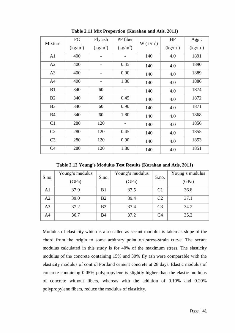
Page | 41
Table 2.11 Mix Proportion (Karahan and Atis, 2011)
Mixture PC
(kg/m3)
Fly ash
(kg/m3)
PP fiber
(kg/m3) W (lt/m3)
HP
(kg/m3)
Aggr.
(kg/m3)
A1 400 - - 140 4.0 1891
A2 400 - 0.45 140 4.0 1890
A3 400 - 0.90 140 4.0 1889
A4 400 - 1.80 140 4.0 1886
B1 340 60 - 140 4.0 1874
B2 340 60 0.45 140 4.0 1872
B3 340 60 0.90 140 4.0 1871
B4 340 60 1.80 140 4.0 1868
C1 280 120 - 140 4.0 1856
C2 280 120 0.45 140 4.0 1855
C3 280 120 0.90 140 4.0 1853
C4 280 120 1.80 140 4.0 1851
Table 2.12 Young’s Modulus Test Results (Karahan and Atis, 2011)
S.no. Young’s mudulus
(GPa) S.no.
Young’s mudulus
(GPa) S.no.
Young’s mudulus
(GPa)
A1 37.9 B1 37.5 C1 36.8
A2 39.0 B2 39.4 C2 37.1
A3 37.2 B3 37.4 C3 34.2
A4 36.7 B4 37.2 C4 35.3
Modulus of elasticity which is also called as secant modulus is taken as slope of the
chord from the origin to some arbitrary point on stress-strain curve. The secant
modulus calculated in this study is for 40% of the maximum stress. The elasticity
modulus of the concrete containing 15% and 30% fly ash were comparable with the
elasticity modulus of control Portland cement concrete at 28 days. Elastic modulus of
concrete containing 0.05% polypropylene is slightly higher than the elastic modulus
of concrete without fibers, whereas with the addition of 0.10% and 0.20%
polypropylene fibers, reduce the modulus of elasticity.
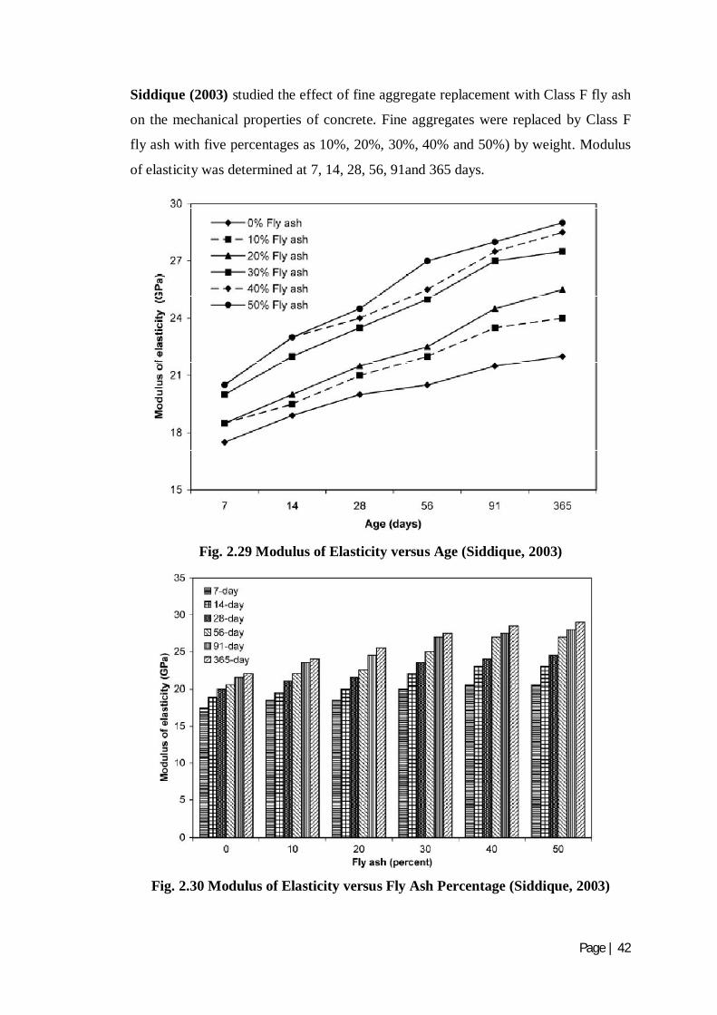
Page | 42
Siddique (2003) studied the effect of fine aggregate replacement with Class F fly ash
on the mechanical properties of concrete. Fine aggregates were replaced by Class F
fly ash with five percentages as 10%, 20%, 30%, 40% and 50%) by weight. Modulus
of elasticity was determined at 7, 14, 28, 56, 91and 365 days.
Fig. 2.29 Modulus of Elasticity versus Age (Siddique, 2003)
Fig. 2.30 Modulus of Elasticity versus Fly Ash Percentage (Siddique, 2003)
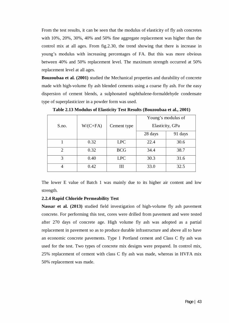
Page | 43
From the test results, it can be seen that the modulus of elasticity of fly ash concretes
with 10%, 20%, 30%, 40% and 50% fine aggregate replacement was higher than the
control mix at all ages. From fig.2.30, the trend showing that there is increase in
young’s modulus with increasing percentages of FA. But this was more obvious
between 40% and 50% replacement level. The maximum strength occurred at 50%
replacement level at all ages.
Bouzoubaa et al. (2001) studied the Mechanical properties and durability of concrete
made with high-volume fly ash blended cements using a coarse fly ash. For the easy
dispersion of cement blends, a sulphonated naphthalene-formaldehyde condensate
type of superplasticizer in a powder form was used.
Table 2.13 Modulus of Elasticity Test Results (Bouzoubaa et al., 2001)
S.no. W/(C+FA) Cement type
Young’s modulus of
Elasticity, GPa
28 days 91 days
1 0.32 LPC 22.4 30.6
2 0.32 BCG 34.4 38.7
3 0.40 LPC 30.3 31.6
4 0.42 III 33.0 32.5
The lower E value of Batch 1 was mainly due to its higher air content and low
strength.
2.2.4 Rapid Chloride Permeability Test
Nassar et al. (2013) studied field investigation of high-volume fly ash pavement
concrete. For performing this test, cores were drilled from pavement and were tested
after 270 days of concrete age. High volume fly ash was adopted as a partial
replacement in pavement so as to produce durable infrastructure and above all to have
an economic concrete pavements. Type 1 Portland cement and Class C fly ash was
used for the test. Two types of concrete mix designs were prepared. In control mix,
25% replacement of cement with class C fly ash was made, whereas in HVFA mix
50% replacement was made.
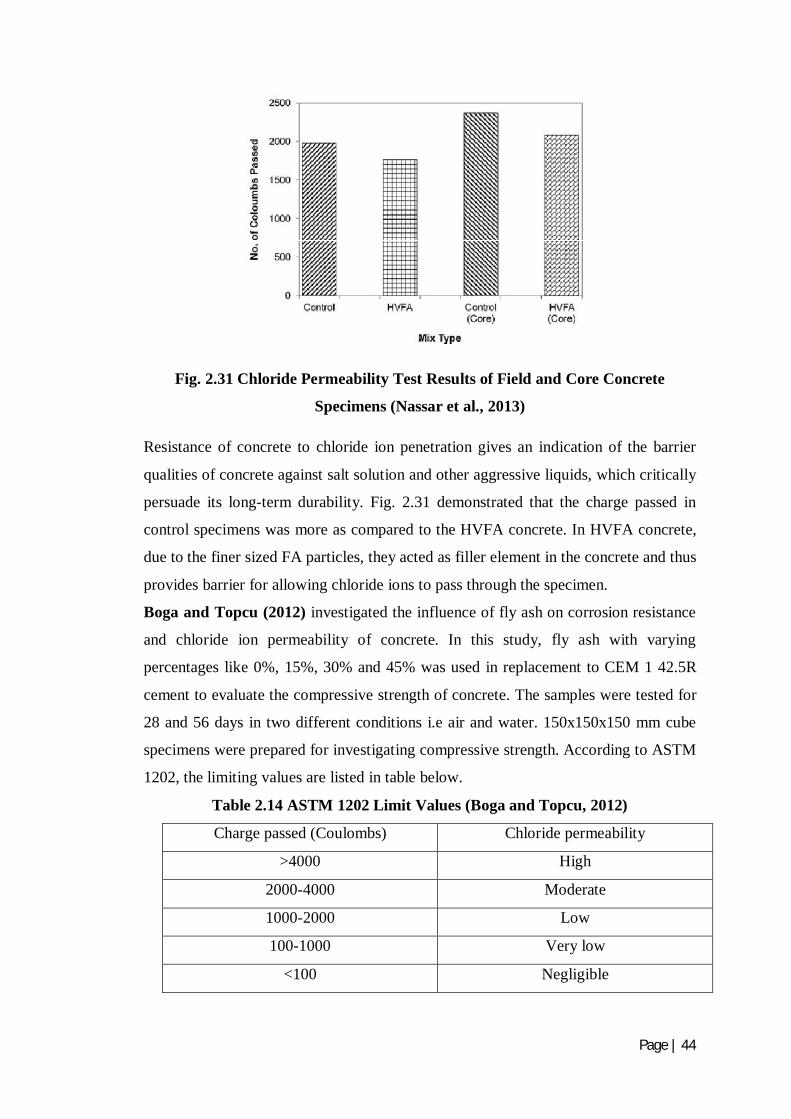
Page | 44
Fig. 2.31 Chloride Permeability Test Results of Field and Core Concrete
Specimens (Nassar et al., 2013)
Resistance of concrete to chloride ion penetration gives an indication of the barrier
qualities of concrete against salt solution and other aggressive liquids, which critically
persuade its long-term durability. Fig. 2.31 demonstrated that the charge passed in
control specimens was more as compared to the HVFA concrete. In HVFA concrete,
due to the finer sized FA particles, they acted as filler element in the concrete and thus
provides barrier for allowing chloride ions to pass through the specimen.
Boga and Topcu (2012) investigated the influence of fly ash on corrosion resistance
and chloride ion permeability of concrete. In this study, fly ash with varying
percentages like 0%, 15%, 30% and 45% was used in replacement to CEM 1 42.5R
cement to evaluate the compressive strength of concrete. The samples were tested for
28 and 56 days in two different conditions i.e air and water. 150x150x150 mm cube
specimens were prepared for investigating compressive strength. According to ASTM
1202, the limiting values are listed in table below.
Table 2.14 ASTM 1202 Limit Values (Boga and Topcu, 2012)
Charge passed (Coulombs) Chloride permeability
>4000 High
2000-4000 Moderate
1000-2000 Low
100-1000 Very low
<100 Negligible
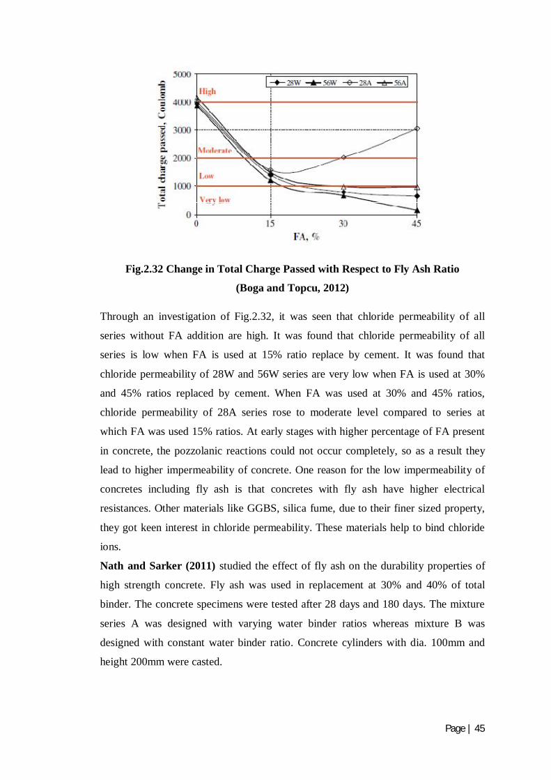
Page | 45
Fig.2.32 Change in Total Charge Passed with Respect to Fly Ash Ratio
(Boga and Topcu, 2012)
Through an investigation of Fig.2.32, it was seen that chloride permeability of all
series without FA addition are high. It was found that chloride permeability of all
series is low when FA is used at 15% ratio replace by cement. It was found that
chloride permeability of 28W and 56W series are very low when FA is used at 30%
and 45% ratios replaced by cement. When FA was used at 30% and 45% ratios,
chloride permeability of 28A series rose to moderate level compared to series at
which FA was used 15% ratios. At early stages with higher percentage of FA present
in concrete, the pozzolanic reactions could not occur completely, so as a result they
lead to higher impermeability of concrete. One reason for the low impermeability of
concretes including fly ash is that concretes with fly ash have higher electrical
resistances. Other materials like GGBS, silica fume, due to their finer sized property,
they got keen interest in chloride permeability. These materials help to bind chloride
ions.
Nath and Sarker (2011) studied the effect of fly ash on the durability properties of
high strength concrete. Fly ash was used in replacement at 30% and 40% of total
binder. The concrete specimens were tested after 28 days and 180 days. The mixture
series A was designed with varying water binder ratios whereas mixture B was
designed with constant water binder ratio. Concrete cylinders with dia. 100mm and
height 200mm were casted.

Page | 46
Table 2.15 Concrete Mix Proportion (Nath and Sarker, 2011)
Series Mix ID
Binder Superplasticiser
(kg/m3) w/b
Slump
(mm) FA (%) Cement
(kg/m3)
A
A-00 0 355 5.11 0.41 140
A-30 30 308 4.77 0.32 170
A-40 40 264 4.75 0.31 185
B
B-00 0 517 6.77 0.29 150
B-30 30 362 4.80 0.29 175
B-40 40 311 4.24 0.29 160
Table 2.16 Rapid Chloride Permeability Test Results (Nath and Sarker, 2011)
Mix ID Chloride permeability (Coulomb)
28 days 180 days
A-00 2722.0 1652.5
A-30 1757.5 573.0
A-40 1493.0 489.0
B-00 2070.5 910.0
B-30 1881.0 466.0
B-40 1574.0 566.5
Penetrability of Cl- reduced with the increase of fly ash in the mixtures. At 180 days,
the Cl- penetration level decreased to ‘Very Low’ for the fly ash concretes. The Cl-
penetration values of the fly ash concretes are less than those of the corresponding
control concretes at this age. The fly ash concretes in Series A resulted in 35% to 45%
reduced Cl- permeability to that of control concrete at 28 days which further reduced
as 65% to 70% in 180 days. Resistance to chloride penetration increased with the
increase in fly ash content from 30% to 40% of total binder. On the other hand, for
concretes of Series B, inclusion of fly ash reduced Cl- permeability up to 24% at 28
days which further reduced up to 48% at 180 days. The concrete with 40% fly ash has

Page | 47
shown slightly higher Cl- penetrability than that with 30% fly ash at 180 days.
However, they both were in the range of ‘very low’ value of charge passed.
Bouzoubaa et al. (2001) studied the Mechanical properties and durability of concrete
made with high-volume fly ash blended cements using a coarse fly ash. For the easy
dispersion of cement blends, a sulphonated naphthalene-formaldehyde condensate
type of superplasticizer in a powder form was used.
Table 2.17 Resistance to Chloride-Ion Penetration (Bouzoubaa et al., 2001)
S.no. W/(C+FA) Cement type Total charge passed, coulombs
28 days 91 days 365 days
1 0.32 LPC 1170 320 110
2 0.32 BCG 333 290 105
3 0.40 LPC 2580 2140 n.a
4 0.42 III 2432 2100 n.a
At 91 days, the total charge passed, in coulombs (C), was less than 400 C for the
HVFA concretes compared with > 2000 C for the control concrete. The concrete
made with the blended cement BCG (Mixture 2) showed higher resistance to the
chloride-ion penetration at 28 days than the mixture in which fly ash had been added
as a separate ingredient at the concrete mixer. However, at 91 days, the resistance of
these two HVFA concrete mixtures was similar.
2.3 SUMMARY Literature on the utilization of carbon nanotubes plus fly ash is not extensive. Only
few studies have been reported on their use to evaluate mechanical as well as
durability properties. Therefore, the present study put some contribution to the
literature for the same.
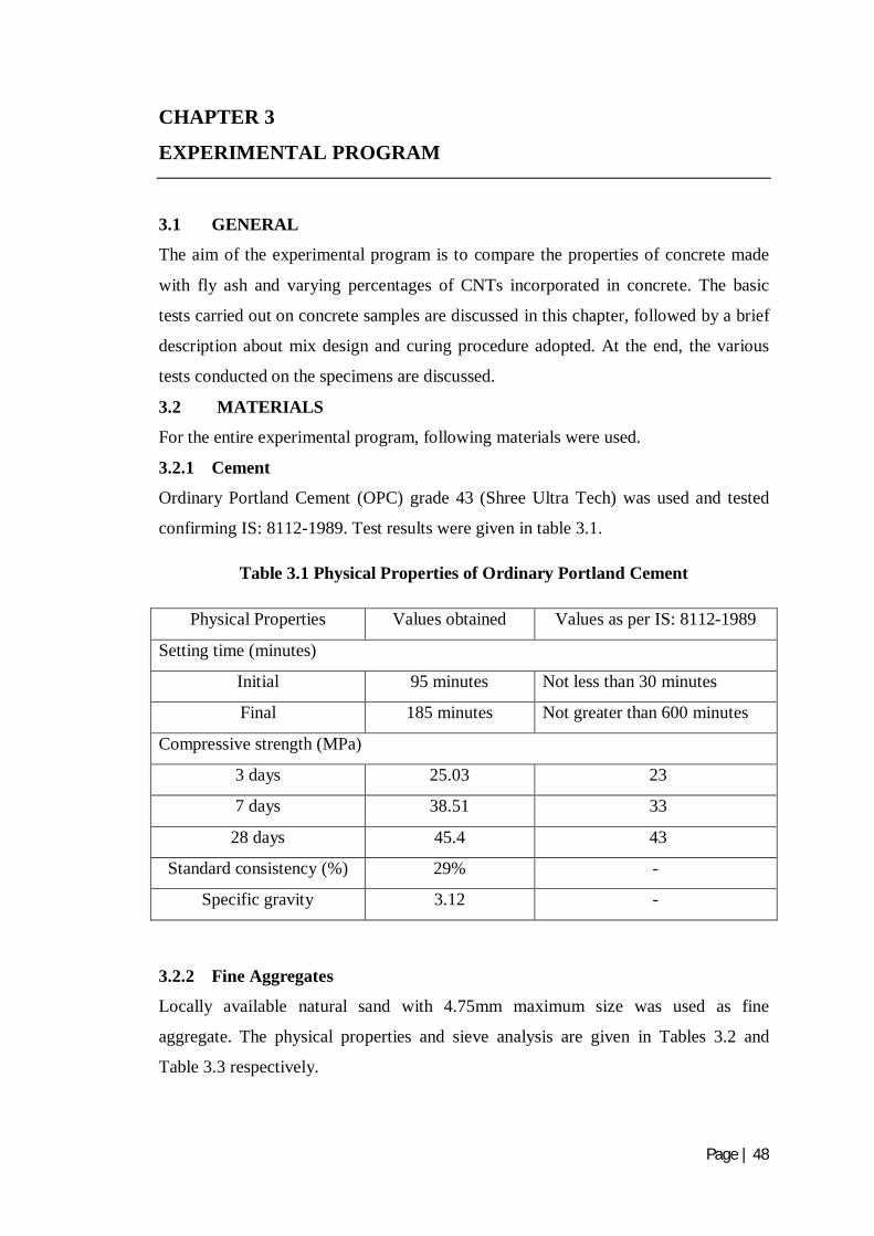
Page | 48
CHAPTER 3
EXPERIMENTAL PROGRAM
3.1 GENERAL
The aim of the experimental program is to compare the properties of concrete made
with fly ash and varying percentages of CNTs incorporated in concrete. The basic
tests carried out on concrete samples are discussed in this chapter, followed by a brief
description about mix design and curing procedure adopted. At the end, the various
tests conducted on the specimens are discussed.
3.2 MATERIALS
For the entire experimental program, following materials were used.
3.2.1 Cement
Ordinary Portland Cement (OPC) grade 43 (Shree Ultra Tech) was used and tested
confirming IS: 8112-1989. Test results were given in table 3.1.
Table 3.1 Physical Properties of Ordinary Portland Cement
Physical Properties Values obtained Values as per IS: 8112-1989
Setting time (minutes)
Initial 95 minutes Not less than 30 minutes
Final 185 minutes Not greater than 600 minutes
Compressive strength (MPa)
3 days 25.03 23
7 days 38.51 33
28 days 45.4 43
Standard consistency (%) 29% -
Specific gravity 3.12 -
3.2.2 Fine Aggregates
Locally available natural sand with 4.75mm maximum size was used as fine
aggregate. The physical properties and sieve analysis are given in Tables 3.2 and
Table 3.3 respectively.
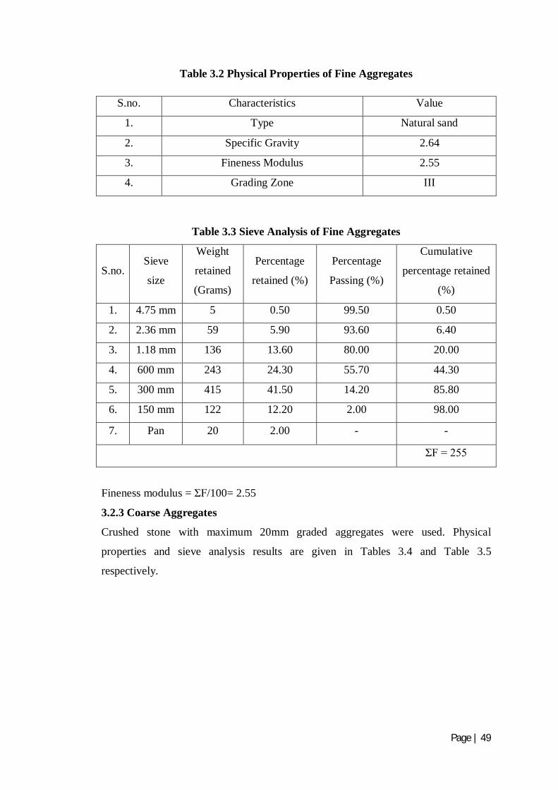
Page | 49
Table 3.2 Physical Properties of Fine Aggregates
S.no. Characteristics Value
1. Type Natural sand
2. Specific Gravity 2.64
3. Fineness Modulus 2.55
4. Grading Zone III
Table 3.3 Sieve Analysis of Fine Aggregates
S.no. Sieve
size
Weight
retained
(Grams)
Percentage
retained (%)
Percentage
Passing (%)
Cumulative
percentage retained
(%)
1. 4.75 mm 5 0.50 99.50 0.50
2. 2.36 mm 59 5.90 93.60 6.40
3. 1.18 mm 136 13.60 80.00 20.00
4. 600 mm 243 24.30 55.70 44.30
5. 300 mm 415 41.50 14.20 85.80
6. 150 mm 122 12.20 2.00 98.00
7. Pan 20 2.00 - -
ΣF = 255
Fineness modulus = ΣF/100= 2.55
3.2.3 Coarse Aggregates
Crushed stone with maximum 20mm graded aggregates were used. Physical
properties and sieve analysis results are given in Tables 3.4 and Table 3.5
respectively.
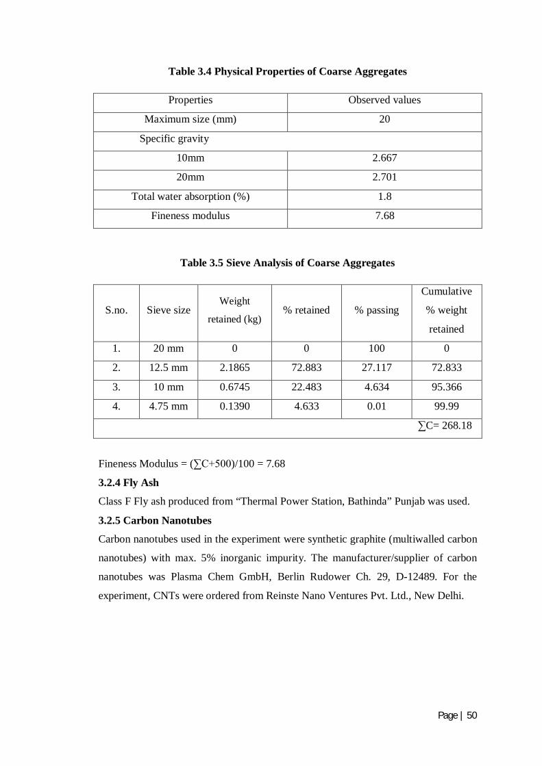
Page | 50
Table 3.4 Physical Properties of Coarse Aggregates
Properties Observed values
Maximum size (mm) 20
Specific gravity
10mm 2.667
20mm 2.701
Total water absorption (%) 1.8
Fineness modulus 7.68
Table 3.5 Sieve Analysis of Coarse Aggregates
S.no. Sieve size Weight
retained (kg) % retained
% passing
Cumulative
% weight
retained
1. 20 mm 0 0 100 0
2. 12.5 mm 2.1865 72.883 27.117 72.833
3. 10 mm 0.6745 22.483 4.634 95.366
4. 4.75 mm 0.1390 4.633 0.01 99.99
∑C= 268.18
Fineness Modulus = (∑C+500)/100 = 7.68
3.2.4 Fly Ash
Class F Fly ash produced from “Thermal Power Station, Bathinda” Punjab was used.
3.2.5 Carbon Nanotubes
Carbon nanotubes used in the experiment were synthetic graphite (multiwalled carbon
nanotubes) with max. 5% inorganic impurity. The manufacturer/supplier of carbon
nanotubes was Plasma Chem GmbH, Berlin Rudower Ch. 29, D-12489. For the
experiment, CNTs were ordered from Reinste Nano Ventures Pvt. Ltd., New Delhi.

Page | 51
Table 3.6 Physical Properties of CNTs
Physical property Observed Values
Form Powder
Colour Black
Carbon purity Min. 95%
Number of Walls 3-15
Outer diameter 5-20nm
Inner diameter 2-6nm
Length 1-10µm
Apparent density 0.15-0.35g/cm3
Loose agglomerate size 0.1-3mm
Flash point >290 ̊C
Danger of explosion At concentrations 50g/m3 and higher
Density at 20 C̊ 0,15 g/cm3
Water Insoluble
3.2.6 Water
Generally, water that is suitable for drinking is satisfactory for use in concrete. Water
from lakes and streams that contain marine life also usually is suitable. When water is
obtained from sources mentioned above, no sampling is necessary. When it is
supposed that water may contain sewage, mine water, or wastes from industrial plants
or canneries, it should not be used in concrete unless tests indicate that it is
satisfactory. In the present experimental programme, potable tap water is used for
casting.
3.3 DISPERSION OF CNTs
3.3.1 Ultrasonicator Bath As CNTs are insoluble in water, so to make their use as an additive in concrete, they
should dispersed in water by making use of ultrasonicator bath. CNTs got dispersed in
water after sonication in the bath tubs for 1 hour. In liquid, the rapid vibration of the
tip causes cavitation, the formation and violent collapse of microscopic bubbles. The
collapse of thousands of cavitation bubbles releases tremendous energy in the
cavitation field. Objects and surfaces within the cavitation field are “processed.” By

Page | 52
increasing the amplitude setting, cavitation intensity within the sample is also
increased. 3.4 METHODOLOGY ADOPTED FOR MIX DESIGN
Mix design is a process of selecting suitable ingredients for concrete and determining
their proportions which would produce economical concrete. The proportioning of the
ingredients of concrete is an important segment of concrete technology as it ensures
quality and economy. For obtaining the concrete of desired performance
characteristics, the component materials should be selected likewise. Then by
considering these components, appropriate mix design is prepared.
3.4.1 Design of Concrete Mix
The compressive strength is said to be the index of quality of concrete. Therefore the
design mix should be prepared keeping in view compressive strength of concrete with
adequate workability so that the fresh concrete can be properly mixed, placed and
compacted. The proportions for the mix were calculated adopting the requirements of
water as specified in IS: 10262-2009.
The following three steps must be followed for proportioning of concrete mixes.
(i) Selection of suitable ingredients-cement, supplementary cementing materials,
aggregates, and water and chemical admixtures (if required).
(ii) Determination of the relative quantities of components to have economical
concrete, that has desired rheological properties i.e. strength and durability.
(iii) Careful quality control of every phase of the concrete making process.
In the present study Mix Design (Design value at the age of 28 days) grade concrete is
done according to BIS: 10262-2009
Design mix
Degree of quality control expected at site = Good
Max. Size of aggregate used = 20mm
Water/cement = 0.5
Fly ash = 20% by weight of cement
Ingredients of concrete are listed in table 3.7
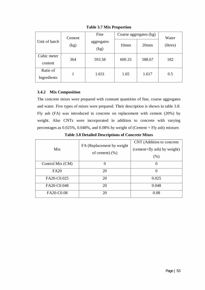
Page | 53
Table 3.7 Mix Proportion
Unit of batch Cement
(kg)
Fine
aggregates
(kg)
Coarse aggregates (kg) Water
(litres) 10mm 20mm
Cubic meter
content 364 593.58 600.33 588.67 182
Ratio of
Ingredients 1 1.631 1.65 1.617 0.5
3.4.2 Mix Composition
The concrete mixes were prepared with constant quantities of fine, coarse aggregates
and water. Five types of mixes were prepared. Their description is shown in table 3.8.
Fly ash (FA) was introduced in concrete on replacement with cement (20%) by
weight. Also CNTs were incorporated in addition to concrete with varying
percentages as 0.025%, 0.048%, and 0.08% by weight of (Cement + Fly ash) mixture.
Table 3.8 Detailed Descriptions of Concrete Mixes
Mix FA (Replacement by weight
of cement) (%)
CNT (Addition to concrete
(cement+fly ash) by weight)
(%)
Control Mix (CM) 0 0
FA20 20 0
FA20-C0.025 20 0.025
FA20-C0.048 20 0.048
FA20-C0.08 20 0.08
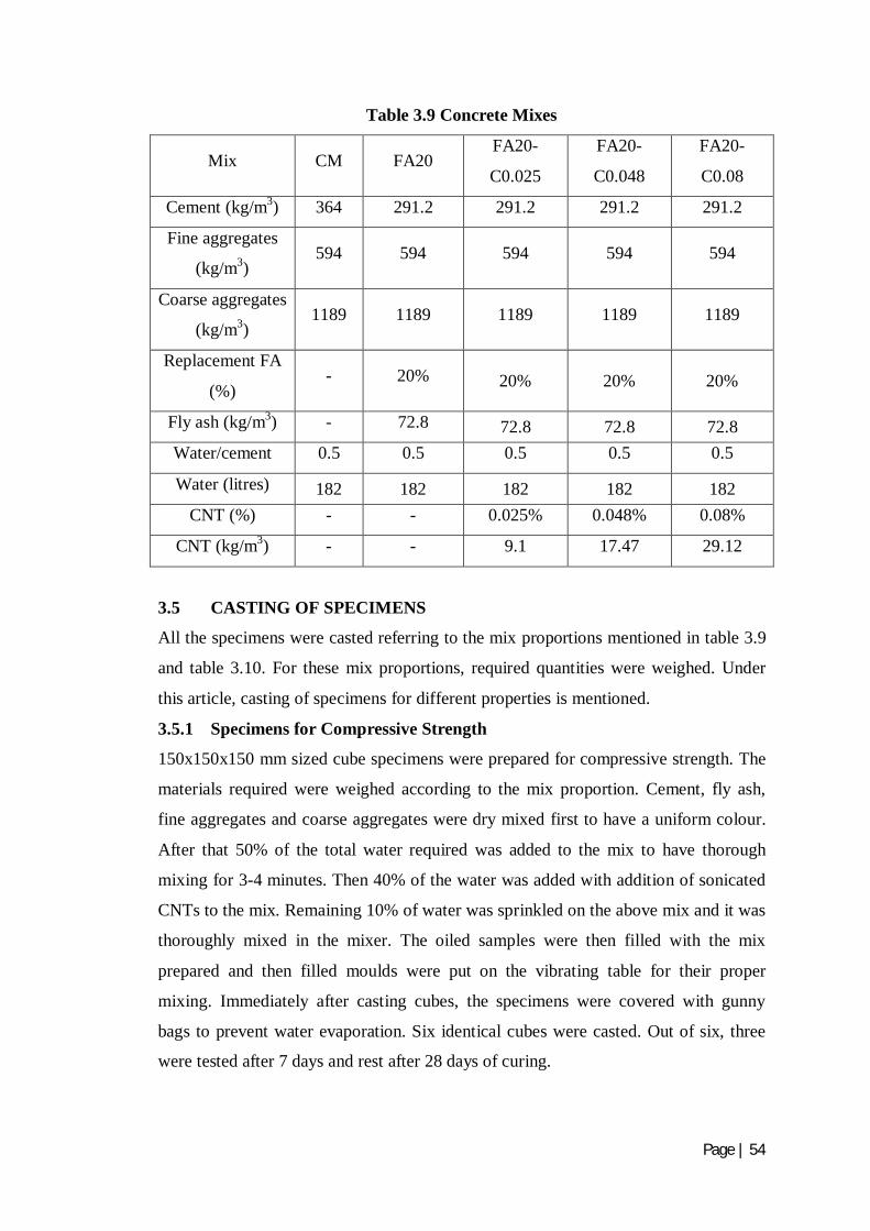
Page | 54
Table 3.9 Concrete Mixes
Mix CM FA20 FA20-
C0.025
FA20-
C0.048
FA20-
C0.08
Cement (kg/m3) 364 291.2 291.2 291.2 291.2
Fine aggregates
(kg/m3) 594 594 594 594 594
Coarse aggregates
(kg/m3) 1189 1189 1189 1189 1189
Replacement FA
(%) - 20% 20% 20% 20%
Fly ash (kg/m3) - 72.8 72.8 72.8 72.8 Water/cement 0.5 0.5 0.5 0.5 0.5
Water (litres) 182 182 182 182 182 CNT (%) - - 0.025% 0.048% 0.08%
CNT (kg/m3) - - 9.1 17.47 29.12
3.5 CASTING OF SPECIMENS
All the specimens were casted referring to the mix proportions mentioned in table 3.9
and table 3.10. For these mix proportions, required quantities were weighed. Under
this article, casting of specimens for different properties is mentioned.
3.5.1 Specimens for Compressive Strength
150x150x150 mm sized cube specimens were prepared for compressive strength. The
materials required were weighed according to the mix proportion. Cement, fly ash,
fine aggregates and coarse aggregates were dry mixed first to have a uniform colour.
After that 50% of the total water required was added to the mix to have thorough
mixing for 3-4 minutes. Then 40% of the water was added with addition of sonicated
CNTs to the mix. Remaining 10% of water was sprinkled on the above mix and it was
thoroughly mixed in the mixer. The oiled samples were then filled with the mix
prepared and then filled moulds were put on the vibrating table for their proper
mixing. Immediately after casting cubes, the specimens were covered with gunny
bags to prevent water evaporation. Six identical cubes were casted. Out of six, three
were tested after 7 days and rest after 28 days of curing.

Page | 55
3.5.2 Specimens for Split Tensile Strength
150x150x150 mm sized cube specimens were prepared for split tensile strength. The
materials required were weighed according to the mix proportion. Cement, fly ash,
fine aggregates and coarse aggregates were dry mixed first to have a uniform colour.
After that 50% of the total water required was added to the mix to have thorough
mixing for 3-4 minutes. Then 40% of the water was added with addition of sonicated
CNTs to the mix. Remaining 10% of water was sprinkled on the above mix and it was
thoroughly mixed in the mixer. The oiled samples were then filled with the mix
prepared and then filled moulds were put on the vibrating table for their proper
mixing. Immediately after casting cubes, the specimens were covered with gunny
bags to prevent water evaporation. Six identical cubes were casted. Out of six, three
were tested after 7 days and rest after 28 days of curing.
3.5.3 Specimens for Young’s Modulus
Diameter 150mm and 300mm length sized cylinder were casted for young’s modulus.
The materials required were weighed according to the mix proportion. Cement, fly
ash, fine aggregates and coarse aggregates were dry mixed first to have a uniform
colour. After that 50% of the total water required was added to the mix to have
thorough mixing for 3-4 minutes. Then 40% of the water was added with addition of
sonicated CNTs to the mix. Remaining 10% of water was sprinkled on the above mix
and it was thoroughly mixed in the mixer. The oiled samples were then filled with the
mix prepared and then filled moulds were put on the vibrating table for their proper
mixing. Immediately after casting cylinders, the specimens were covered with gunny
bags to prevent water evaporation. Six identical cylinders were casted. Out of six,
three were tested after 7 days and rest after 28 days of curing.
3.5.4 Specimens for Rapid Chloride Permeability
The resistance to chloride penetration of concrete was determined by casting cylinders
of size diameter 100mm and length 200mm. The materials required were weighed
according to the mix proportion. Cement, fly ash, fine aggregates and coarse
aggregates were dry mixed first to have a uniform colour. After that 50% of the total
water required was added to the mix to have thorough mixing for 3-4 minutes. Then
40% of the water was added with addition of sonicated CNTs to the mix. Remaining
10% of water was sprinkled on the above mix and it was thoroughly mixed in the
mixer. The oiled samples were then filled with the mix prepared and then filled
moulds were put on the vibrating table for their proper mixing. Immediately after

Page | 56
casting cylinders, the specimens were covered with gunny bags to prevent water
evaporation. Six identical cylinders were casted. Out of six, three were tested after 7
days and rest after 28 days of curing.
3.6 TESTING OF SPECIMENS
After casting, specimens were tested after 7 and 28 days of curing. Under this article,
the procedure followed for testing of specimens is mentioned for evaluating various
properties like compressive strength, splitting tensile strength, young’s modulus of
elasticity and rapid chloride permeability of concrete.
3.6.1 Mechanical Properties
3.6.1.1 Compressive Strength
Specimens were demoulded after 24 hours of casting. Then they were poured in
curing tank for the predefined time. At the age of testing, specimens were taken out of
the tank and allowed surface drying for 10-15 minutes. Specimens were tested in
Compression Testing Machine (CTM) at the load rate of 5 kN/sec specified as per IS:
516-1959. CTM has the capacity of 5000kN. The failure load was then evaluated.
Fig. 3.1 Setup for Compressive Strength
3.6.1.2 Split Tensile Strength
Specimens were demoulded after 24 hours of casting. Then they were poured in
curing tank for the predefined time. At the age of testing, specimens were taken out of

Page | 57
the tank and allowed surface drying for 10-15 minutes. Specimens were tested in
Universal testing machine (UTM) at the load rate of 70 kN/min. UTM has the load
capacity of 1000kN. The failure load was then evaluated. The formula used is
Split tensile strength = . ×
²
P = Failure load, in N
S = Side of cube, in mm
Fig. 3.2 Setup for Split Tensile Strength
3.6.1.3 Young’s Modulus
The modulus of elasticity or Young’s modulus is defined as the slope of the stress
strain curve with the proportional limit of a material. Specimens were demoulded
after 24 hours of casting. Then they were poured in curing tank for the predefined
time. At the age of testing, specimens were taken out of the tank and allowed surface
drying for 10-15 minutes. The young’s modulus was evaluated using extensiometer in
Universal testing machine (UTM). The extensiometer consist of two frames for
clamping to the specimens by means of three tightening screws. Two spacers hold the
two frames in positions. Dial gauge was already fitted on the extensiometer, which
provides deflection. The least count of dial guage was 0.025mm. 3 cycles of loading
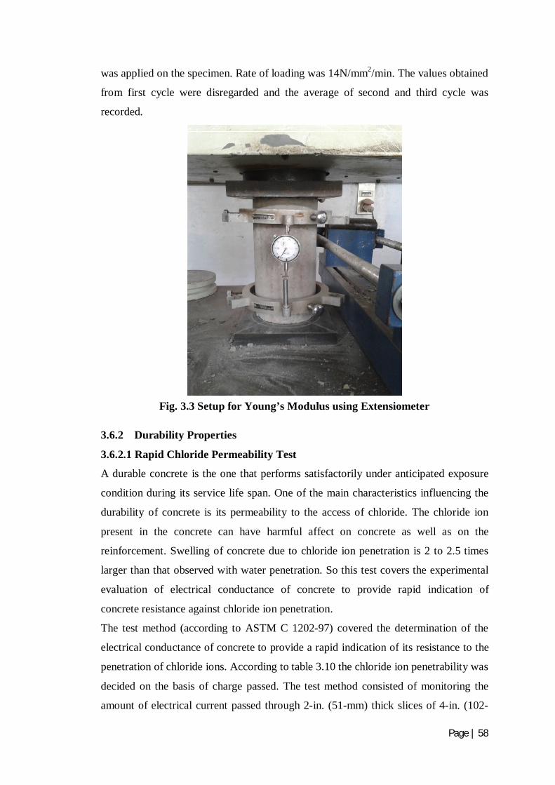
Page | 58
was applied on the specimen. Rate of loading was 14N/mm2/min. The values obtained
from first cycle were disregarded and the average of second and third cycle was
recorded.
Fig. 3.3 Setup for Young’s Modulus using Extensiometer
3.6.2 Durability Properties
3.6.2.1 Rapid Chloride Permeability Test
A durable concrete is the one that performs satisfactorily under anticipated exposure
condition during its service life span. One of the main characteristics influencing the
durability of concrete is its permeability to the access of chloride. The chloride ion
present in the concrete can have harmful affect on concrete as well as on the
reinforcement. Swelling of concrete due to chloride ion penetration is 2 to 2.5 times
larger than that observed with water penetration. So this test covers the experimental
evaluation of electrical conductance of concrete to provide rapid indication of
concrete resistance against chloride ion penetration.
The test method (according to ASTM C 1202-97) covered the determination of the
electrical conductance of concrete to provide a rapid indication of its resistance to the
penetration of chloride ions. According to table 3.10 the chloride ion penetrability was
decided on the basis of charge passed. The test method consisted of monitoring the
amount of electrical current passed through 2-in. (51-mm) thick slices of 4-in. (102-
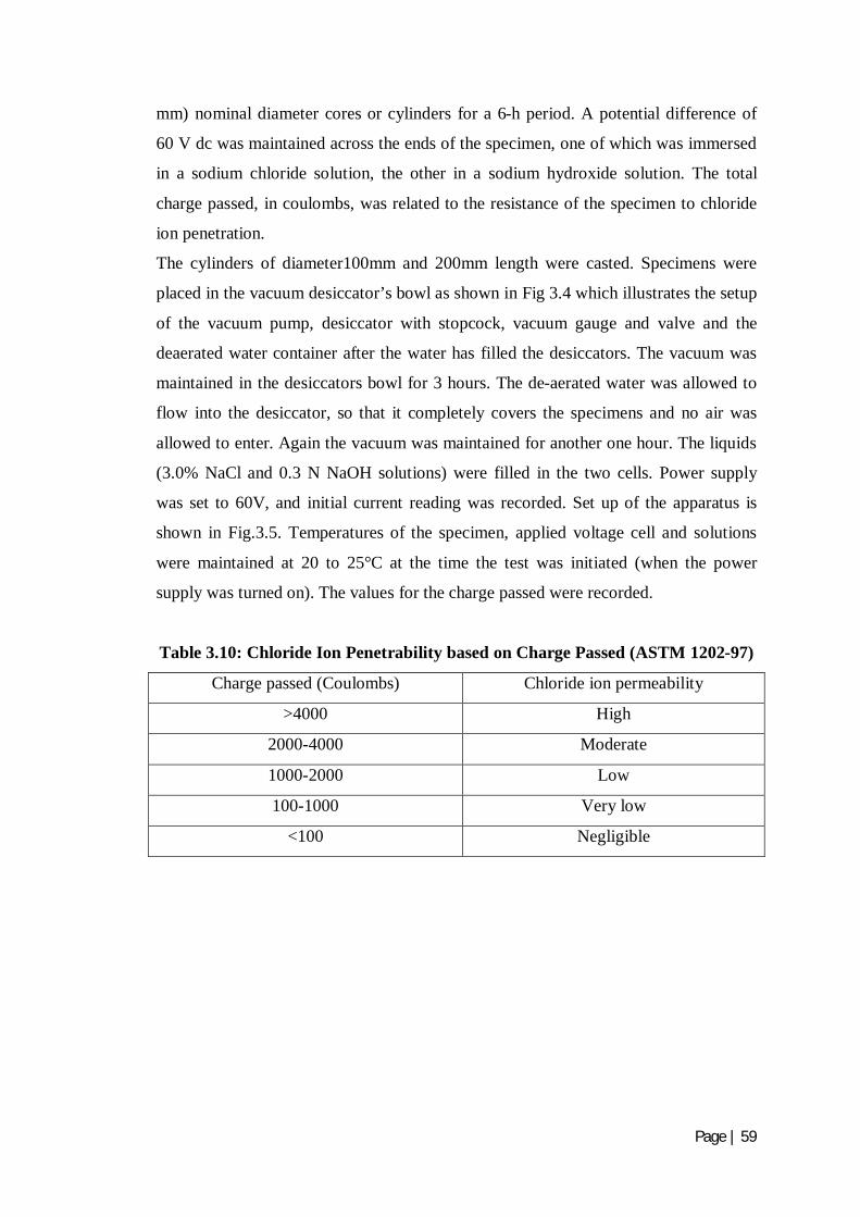
Page | 59
mm) nominal diameter cores or cylinders for a 6-h period. A potential difference of
60 V dc was maintained across the ends of the specimen, one of which was immersed
in a sodium chloride solution, the other in a sodium hydroxide solution. The total
charge passed, in coulombs, was related to the resistance of the specimen to chloride
ion penetration.
The cylinders of diameter100mm and 200mm length were casted. Specimens were
placed in the vacuum desiccator’s bowl as shown in Fig 3.4 which illustrates the setup
of the vacuum pump, desiccator with stopcock, vacuum gauge and valve and the
deaerated water container after the water has filled the desiccators. The vacuum was
maintained in the desiccators bowl for 3 hours. The de-aerated water was allowed to
flow into the desiccator, so that it completely covers the specimens and no air was
allowed to enter. Again the vacuum was maintained for another one hour. The liquids
(3.0% NaCl and 0.3 N NaOH solutions) were filled in the two cells. Power supply
was set to 60V, and initial current reading was recorded. Set up of the apparatus is
shown in Fig.3.5. Temperatures of the specimen, applied voltage cell and solutions
were maintained at 20 to 25°C at the time the test was initiated (when the power
supply was turned on). The values for the charge passed were recorded.
Table 3.10: Chloride Ion Penetrability based on Charge Passed (ASTM 1202-97)
Charge passed (Coulombs) Chloride ion permeability
>4000 High
2000-4000 Moderate
1000-2000 Low
100-1000 Very low
<100 Negligible
Related Documents