Efficient self-synchronised blind audio watermarking system based on time domain and FFT amplitude modification David Meg´ ıas Jordi Serra-Ruiz Mehdi Fallahpour Estudis d’Inform` atica, Multim` edia i Telecomunicaci´ o, Universitat Oberta de Catalunya, Rambla del Poblenou, 156, 08018 Barcelona (Spain), Tel.: +34 93 326 36 00 Fax: +34 93 356 88 22 {dmegias,jserrai,mfallahpour}@uoc.edu March 11, 2010 1

Welcome message from author
This document is posted to help you gain knowledge. Please leave a comment to let me know what you think about it! Share it to your friends and learn new things together.
Transcript

Efficient self-synchronised blind audio watermarking system based
on time domain and FFT amplitude modification
David Megıas Jordi Serra-Ruiz
Mehdi Fallahpour
Estudis d’Informatica, Multimedia i Telecomunicacio,
Universitat Oberta de Catalunya,
Rambla del Poblenou, 156,
08018 Barcelona (Spain),
Tel.: +34 93 326 36 00
Fax: +34 93 356 88 22
{dmegias,jserrai,mfallahpour}@uoc.edu
March 11, 2010
1

Abstract
Many audio watermarking schemes divide the audio signal into several blocks such that part of the watermark is
embedded into each of them. One of the key issues in these block-oriented watermarking schemes is to preserve the
synchronisation, i.e. to recover the exact position of each block in the mark recovery process. In this paper, a novel
time domain synchronisation technique is presented together with a new blind watermarking scheme which works
in the Discrete Fourier Transform (DFT or FFT) domain. The combined scheme provides excellent imperceptibility
results whilst achieving robustness against typical attacks. Furthermore, the execution of the scheme is fast enough to
be used in real-time applications. The excellent transparency of the embedding algorithm makes it particularly useful
for professional applications, such as the embedding of monitoring information in broadcast signals. The scheme is
also compared with some recent results of the literature.
Keywords: Audio Watermarking, Blind detection, Self-synchronisation, FFT, Transparency
1 Introduction
Digital watermarking deals with the problem of embedding information (a mark) into a digital object (the cover ob-
ject). This field of research has attracted the attention of the scientific community in the last few years. Different
watermarking methods have been suggested for different fields of application, such as copy and access control, au-
thentication and tampering detection, fingerprinting, ownership protection, proof of ownership, information carrier
and broadcast monitoring, among others. Watermarking schemes are often evaluated in terms of four basic properties,
namely, robustness, capacity, transparency and security (see [4] for some formal definitions of these properties).
Watermarking applications have been reported for different digital media including still images, audio and video.
This paper describes a novel audio watermarking scheme which can be applied for ownership protection, proof of
ownership, content monitoring or fingerprinting. The main aim of this research is to obtain an efficient watermarking
method with excellent transparency whilst preserving robustness against typical signal processing attacks. Efficiency
is a key feature in case that the scheme is intended to be applied in real-time systems.
Some remarkable audio watermarking results presented in [30, 29, 7, 10] provide good results in terms of robust-
ness and transparency, but they do not include an explicit synchronisation method. On the other hand, other audio
watermarking schemes divide the cover object into several blocks such that part of the watermark is embedded into
each of them. One of the key issues in these block-oriented watermarking schemes is to preserve the synchronisation,
i.e. to recover the exact position of each block in the mark recovery process. Many audio watermarking schemes in
the literature deal with the synchronisation problem.
In [15], an adaptive synchronisation method consisting of computing an index to maximise a function which de-
pends on the alignment of the embedded mark and the test signal is presented. This method is shown to be robust
2

against different attacks, but requires the computation of the alignment index for each sample, which increases the
computational time and makes its application in real-time systems difficult. A different technique for synchronisation
is suggested in [23], which performs an embedding procedure which works with the whole original signal and re-
quires a cycle correlation operation to be performed at the detector. This mechanism implies the calculation of cyclic
convolution via an FFT algorithm. [17] uses the spread spectrum technology in which the mark is represented by
patterns consisting of sinusoids which are phase-modulated by the elements of a pseudo-random sequence. In this
method, special header patterns are used to recover the synchronisation by maximising the autocorrelation. In order to
compute this autocorrelation, [17] suggests using the FFT with the re-sampling technique and, though this approach
can be quite efficient, it will probably involve more computational burden than most time-domain synchronisation
approaches. [16] suggests a watermarking scheme with inherent robustness against desynchronisation, since the mark
is embedded in the average of the low-frequency sub-band coefficients of the Discrete Wavelet Transform (DWT).
However, no specific method to recover the synchronisation of the embedded bits is presented. In [25], a method
which embeds both the synchronisation and the informational marks in the Discrete Cosine Transform (DCT) domain
is presented. In order to detect the synchronisation segments, the DCT must be applied within the search iteration,
making it unsuitable for real-time applications. In [14], a method which embeds the information mark in the largest
energy region of the DWT transform is presented. This method is based on the assumption that the acceptable attacks,
especially those consisting of cropping parts of the signal, leave those DWT coefficients unchanged. On the other
hand, the synchronisation is achieved applying some statistical methods to estimate the possible scale changes and/or
delays applied to a hypothetically attacked signal. Hence, no specific synchronisation marks are applied, but some
correlation indexes between the marked and the test signal are maximised. The method presented in [28] embeds
both the synchronisation and the information marks in the coefficients of the low-frequency sub-band of the DWT
transform, resulting in an enhanced robustness against common signal processing attacks. In addition, this method
exploits the time-frequency localisation feature of the DWT transform to reduce the computational burden required
for the search of the synchronisation marks. However, this method requires the modification of the segmentation of
the test signal in case that the synchronisation mark is not retrieved in each segment, which may be excessively time
consuming for mark retrieval in real-time applications.
Audio watermarking schemes with a time-domain synchronisation code and a separate watermarking segment have
been suggested in the literature [8, 26]. In [8], the synchronisation code is the 12-bit Barker code “111110011010”
which is embedded in the 13 least significative bits (LSB) of 12 consecutive audio samples. Although this allows
synchronisation to be performed in a very efficient way, the perceptual quality is damaged with many audible clicks at
the synchronisation positions. This method was improved in [26], where the 16-bit Barker code “1111100110101110”
is embedded by modifying the average of a few consecutive samples (five samples in the experiments given in the
3

paper). In fact, the average of these samples is quantised such that an odd number means a ‘1’ and an even number
is a ‘0’. Hence, the quantisation step determines the perceptibility of the mark. However, some audio files require a
large quantisation step to ensure robustness, which results, again, in audible clicks at the synchronisation positions.
The advantage of this kind of synchronisation marks [8, 26] is that the search can be performed in the time domain,
without computing any kind of transform. As the information mark is concerned, [26] embeds the information mark
in the DWT and DCT transform domains. The watermark extraction methods consists of exploring the test signal to
locate a synchronisation mark. Once such a mark has been found, the DWT and DCT transforms are used to extract
the information mark. The audible clicks introduced by both methods can be explained by the easily noticeable peak
distortions they introduce in some samples.
From a computational point of view, the ideas of [8, 26] provide a more efficient synchronisation compared to the
other referred schemes, but the significant audible distortions introduced by them are a relevant drawback when trans-
parency is an intended property. In this paper, we propose a novel time domain synchronisation technique. The chosen
approach makes it possible to use the detector algorithm in real-time applications, due to the efficiency of the time
domain search of the synchronisation marks. In addition, it provides excellent imperceptibility and robustness results,
as shown in the experiments. Apart from the self-synchronisation strategy, this paper presents a novel watermarking
scheme for the information mark. The new scheme stems from the results of the schemes presented in [18, 20, 6],
since it works in the Fast Fourier Transform (FFT) domain by introducing (small) modifications in the amplitude at
some selected frequencies. In addition, the detector for the new scheme is blind (in contrast to those of [18, 20]) and
its execution is fast enough to be used in real-time applications. Furthermore, the modifications introduced in the FFT
domain during the embedding process are minimal and the sorting of the FFT amplitudes is preserved, resulting on
an excellent imperceptibility whilst keeping robustness for the most usual signal processing attacks, as shown in the
experiments presented in Section 4.
The objective of the watermarking system presented in this paper is to introduce only small distortions in the audio
signal, leading to convenient imperceptibility results, as long as some of the embedded marks are recovered for each
file for usual attacks. Hence, it is considered preferable to loose some of the embedded marks as far as no perceptible
distortion is detected in the marked audio file. However, the system is still robust enough such that many of the
embedded marks are recovered after performing typical signal processing attacks.
This paper is organised as follows. Section 2 presents the embedding method for both the synchronisation and the
information marks. In Section 3, the detection of the synchronisation mark and the extraction method of the embedded
information bits are detailed. In Section 4, the suggested scheme is evaluated in terms of imperceptibility, capacity
and robustness, and it is compared with relevant recent results of the literature. Finally, Section 5 summarises the most
relevant conclusions and suggests some directions for future research.
4
2 Embedding method
The watermarking scheme suggested in this paper is described in the following sections.
The embedding process is divided in two separate parts, the embedding of synchronisation marks and the embed-
ding of the information (or protection) watermark. This process is outlined in Fig. 1, where L1 is the number of
samples used for embedding the synchronisation marks, L2 is the number of samples used for embedding the infor-
mation marks, and a gap (“Gap” in the figure) of variable (arbitrary) length separates two consecutive instances of the
embedded marks. This figure represents a segment of the audio file. The embedding positions occur different times
from the first sample (which would be represented farther to the left of the figure) to the end of the audio sequence
(farther to the right).
The synchronisation marks (“SYN” in the figure) are embedded in the time domain as described in Section 2.2,
whereas the information watermark is embedded in the frequency domain as shown in Section 2.3. The detection
process is described in Section 3.
2.1 Notation
The description of both the embedding and retrieval methods provided in the next sections is quite intricate, and a few
notational keys are provided here to make the readability of the paper easier:
s, t, u Sampled time domain audio signals
S Family of time domain audio signals
sn n-th Sample of the signal s
L1, L2, L3 Lengths (in samples) of segments of the audio signal
τs Sampling time
fs = 1/τs Sampling frequency
sstereo Stereo audio signal
sleft, sright Left and right channels of a stereo signal
S Spectrum of the signal s (as obtained using an FFT algorithm)
Sk k-th component of the spectrum S
Mk Magnitude of the k-th spectral component
α, β, γ, . . . Scalar values
σ Permutation function for a set
i, j, k, n Integer subscripts
SYN Synchronisation segment or word
W “Raw” watermark (or mark), with no error correction coding
5

W Encoded watermark (or mark)
B Generic bit sequence
bi i-th bit of the bit sequence B
|·| Magnitude of a complex number, length of a bit sequence, abso-
lute value of a scalar
C Correlation function
T Transparency function
A Family of attacks
Ai A given attack in the family A
2.2 Synchronisation marks
Synchronisation marks are a very relevant issue in practical implementation of audio watermarking schemes. Some
of the audio watermarking methods described in the literature (see [3] for a recent survey of audio watermarking
schemes) use the whole audio signal to embed the mark (in the time domain or in the frequency domain). This
possibility, however, entails two relevant drawbacks. On the one hand, the test signal to be checked for the presence
of the mark is usually required to be synchronised with the marked signal (even when the detector is blind), since
detectors are often position dependent. On the other hand, many of the watermarking methods which do not use
synchronisation marks require to work with the whole signal, which can be extremely costly from a computational
point of view. For example, a 5-minute song sampled 44100 times per second, with two channels and 16 bits (two
bytes) per sample requires 5·60·44100·2·2= 52 920 000 bytes (more than 50 MB) to be stored in the main memory.
If each sample is converted to a floating point number with double precision it will require 4 times this size (namely,
more than 200 MB). If complex mathematical operation, such as a Fourier transform or a Wavelet transform must be
applied to these data, the memory size requirements and the computational burden rocket dramatically. Of course, you
can always divide the signal into blocks of a convenient size prior to the mark embedding process. However, if no
synchronisation recovery system is introduced in the detector, the robustness of these methods against attacks which
alter the number of samples is often seriously weakened.
Synchronisation marks [11] are a convenient way to overcome these drawbacks. This technique makes it possible
to work with blocks of samples by introducing a synchronisation mark which signals the beginning (and sometimes
the end) of a given block. If the embedding and detection algorithms work with blocks of a few seconds instead
of minutes, the efficiency of the system in both memory usage and CPU time increases significantly. In addition,
synchronisation marks usually make it easier to recover the information mark from a (small) fragment of the marked
signal, which enhances the robustness of the system against different signal processing attacks.
6

However, the synchronisation marks must be easy to detect if an efficient watermarking scheme is required. The
simplest way to detect synchronisation mark is to perform some operation with a set of samples (from i to i+L1−1),
where L1 stands for the length, in samples, of the synchronisation mark. If the synchronisation mark is found, then
the presence of the protection mark will be checked in the coming L2 samples. If the synchronisation mark is not
detected, the operation is repeated for the set of samples starting in the next one (from i+ 1 to i+ L1).
In this paper, the samples sn of the original signal are assumed to be in the normalised range [−1, 1]. If they are
read from a RIFF-WAVE file with 16 bits per sample, the integer values can be divided by 215 in order to normalise
them.
The synchronisation method suggested in this paper embeds a given sequence of bits or its inverse1 in L1 = lnsyn
consecutive samples of the audio signal, where l is the length (in bits) of the synchronisation mark. Usually, in the
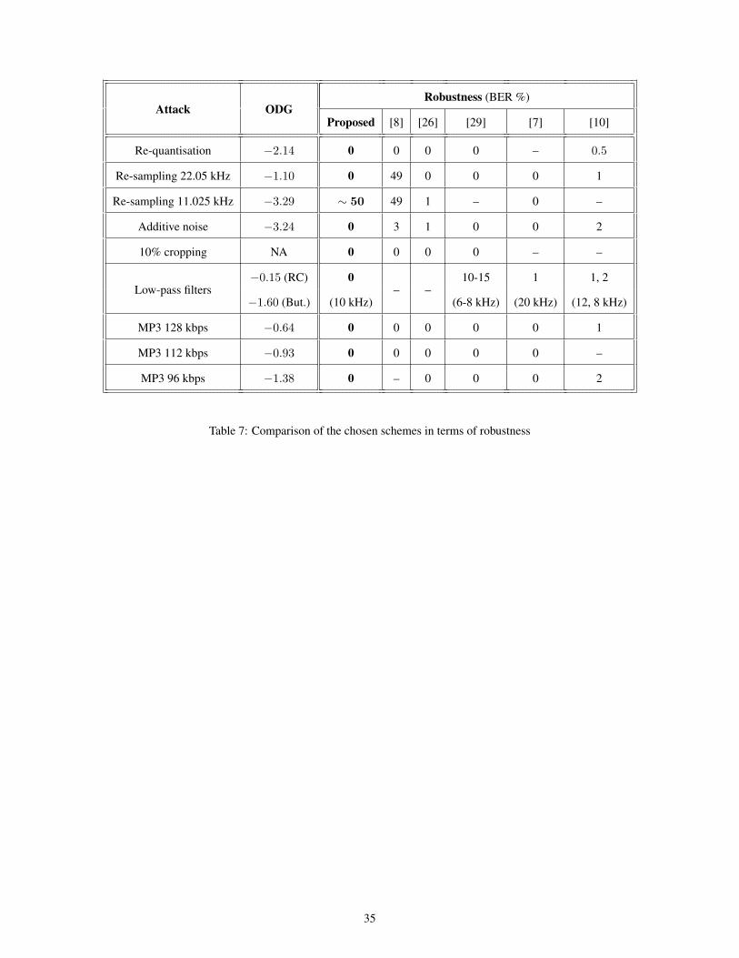
original signal nsyn consecutive samples (for small nsyn) behave as shown in the figure, with a small distance of the
average of internal samples (sp+1 and sp+2) with respect to the average of the extreme points (sp and sp+3). In order
to embed a ‘1’, the inner samples are changed such that their average is greater than that of the extreme points. To
embed a ‘0’, the same idea is applied but replacing the inner values by others slightly lower such that their average
is lower than that of the extreme points. In fact, the replacement is performed only if the embedding condition is not
satisfied, in order to avoid unnecessary distortions of the audio signal.
More precisely, the following embedding method is applied. Let us assume that the synchronisation bit must be
embedded into the samples sp, sp+1, . . . , sp+nsyn−1:
sint :=1
nsyn − 2
p+nsyn−2∑j=p+1
sj
sext :=sp + sp+nsyn−1
2
δ := max {δmin, ϕ |sext|} for some δmin > 0 (e.g. δmin = 10−3) and ϕ > 0 (e.g. ϕ = 0.05)
For j := p to p+ nsyn − 1 do
s′j := sj
EndFor
• To embed a ‘1’:
If sint < sext + δ then
d := sext + δ − sint
For j := p+ 1 to p+ nsyn − 2 do1Since negative and positive correlations are considered equivalent, both codes are equally detected.
7

s′j := sj + d
EndFor
EndIf
• To embed a ‘0’:
If sext < sint + δ then
d := sint + δ − sext
For j := p+ 1 to p+ nsyn − 2 do
s′j := sj − d
EndFor
EndIf
Note that this scheme guarantees that the difference between the average of the external and the inner samples is
at least δ for each synchronisation bit. For the particular case nsyn = 4, a simpler approach can be defined in terms
of the difference between sp + sp+3 and sp+1 + sp+2, but the equations given above can be used for any value of
nsyn ≥ 3.
In all cases, the extreme samples s′p and s′p+nsyn−1 remain unchanged. The tuning parameters for this synchroni-
sation method are nsyn (the number of consecutive samples to embed each bit), δmin (the minimum distance from the
average of the extreme points for bit-embedding) and ϕ (the distortion introduced with respect to the average of the
extreme points), and only nsyn is required for detection, as described in Section 3.
The embedding process of the synchronisation bits is depicted in Figure 2 (for nsyn = 4), where the red ball
represents the average of the extreme points and the green one represents that of the inner points. Please note that
the difference (δ) is deliberately exaggerated in order to make the embedding process more apparent in the figure. In
general, the distortion introduced by the synchronisation bits is much lower than this representation.
In case of stereo signals, the synchronisation mark is embedded in both channels at the same position. Each
channel may contain the positive SYN code (e.g. “11111001”) or the negative one (e.g. “00000110”) irrespective of
the code embedded in the counterpart. This provides robustness against some attacks such as the inversion of samples
(since both the positive and negative SYN codes are considered identical) or the extra stereo attacks in the Stirmark
Benchmark for Audio [13, 12]. The selection of the positive or negative code is performed randomly.
2.3 Mark embedding method
The mark embedding algorithm has been designed following the ideas of [18, 20, 6] to provide robustness against the
typical audio compression systems which rely on models of the Human Auditory System (HAS). The main ideas used
8

in those methods are the following:
1. The mark bits are embedded by disturbing the magnitude of the spectrum of the original signal at some selected
“marking” frequencies.
2. The marking frequencies and the disturbance are chosen to attain a tradeoff between transparency and robust-
ness.
The scheme provided in [18] is based on choosing a set of marking frequencies by comparing the spectra of the
original signal and a compressed-uncompressed version of it. In that scheme, the mark bits are embedded at the fre-
quencies for which both spectra are identical (within some tolerance). However, this choice disturbs the original signal
exactly at the most significant frequencies from a perceptual point of view, which is not convenient as transparency
is concerned. The scheme of [20] introduces some randomness in the process of selecting the marking frequencies,
which makes it possible to improve the transparency of the scheme at the price of loosing some robustness. All those
schemes need to compare the spectrum of the marked signal with that of the original one to recover the embedded
mark. That is, in all cases the detector is informed. On the other hand, [6] interpolates the FFT amplitudes at some
samples based on the neighbouring ones and, if the difference between the real and the interpolated values is lower
than a given threshold, the FFT samples are modified slightly to embed a hidden bit.
The method suggested in this paper inherits the convenient properties of the cited schemes, namely, to provide a
tradeoff between transparency and robustness and to achieve robustness against MP3 compression, but solves the main
drawback of [18, 20] schemes since the detector is blind. In addition, synchronisation marks are introduced making it
possible to work with blocks instead of the full audio signal as in [6].
The mark embedding procedure works as follows. Let L2 = |W |L3 be the size of the watermark embedding
(block), where |W | is the length (in bits) of the mark and L3 is the number of samples chosen to embed each bit.
Without loss of generality, L3 is assumed to be an even number to simplify the notation.
Let s be a fragment of L3 consecutive PCM samples of the original signal. It is assumed that the signal to
be marked is stereo: sstereo = [sleft, sright] and both channels (left and right) are summed up together into a new
“working” signal s = sleft + sright. This operation is a summation of each left sample with the corresponding right
counterpart, and not a concatenation of both signals. In the case of a mono signal, this step must be omitted. Let Sk be
the spectrum of s as computed using a Fast Fourier Transform (FFT) algorithm2 for k = 0, 1, 2, . . . , L3 − 1. Due to
the symmetry property of the FFT, SL3−k = S∗k , for k = 0, 1, 2, . . . , (L3/2)− 1, i.e. the second half of the sequence
Sk are the complex-conjugate values of the elements of the first half.
2Since the original fragment s is a sampled version of a continuous signal, there is a direct relationship between the interval k ∈ [0, N) and the
angular frequency ω ∈ [0, 2π/τ) rad/s, where τ is the sampling interval (usually 1/44100 seconds). Hence, Sk can be thought of as samples of
the spectrum of the continuous signal taken with the interval 2πτL3
.
9

To choose the marking frequencies (elements of Sk), the sequence{S1, S2, . . . , S(L3/2)−1
}is first sorted accord-
ing to magnitude, such that S′ satisfies |S′1| ≤ |S′2| · · · ≤∣∣∣S′(L3/2)−1
∣∣∣ and S′k = Sσ(k) for some permutation
σ : Z(L3/2)−1 −→ Z(L3/2)−1.
Note that the continuous component S0 is discarded since it is not a convenient embedding position. Now, four
consecutive elements of S′ are chosen for embedding a bit, namely S′m, S′m+1, S′m+2 and S′m+3 for a given m
(1 ≤ m ≤ (L3/2)− 3).
To simplify the notation, the following definition Mk = |S′k| is used for the magnitudes of the elements in S′k. The
embedding condition to be checked or enforced is the following:
1. Mm +Mm+3 > Mm+1 +Mm+2 to embed a ‘1’,
2. Mm+1 +Mm+2 > Mm +Mm+3 to embed a ‘0’.
In order to satisfy this condition (with some margin to avoid overlapping between embedded ones and zeroes) the
following condition will be actually enforced:
1. Mm +Mm+3 ≥ α(Mm+1 +Mm+2) to embed a ‘1’,
2. Mm+1 +Mm+2 ≥ α(Mm +Mm+3) to embed a ‘0’.
For some α > 1 (e.g. α = 1.1).
In this procedure, the larger m is, the more significant the disturbed frequencies are, and thus, the less transparent
the method becomes. It must be also taken into account that, for a given segment size (e.g. L3 = 512 samples), audio
compressors tend to preserve the frequencies with greater magnitudes (i.e. the last 10 or 20 elements of S′). Hence, a
convenient choice of m provides a tradeoff between robustness and transparency.
In case that the condition for the embedded bits is not satisfied, the changes to be made to the spectrum S′ are the
following3:
1. To embed a ‘1’ when Mm +Mm+3 < α(Mm+1 +Mm+2).
In this case, Mm and Mm+3 are increased until the condition is fulfilled whilst the sorting of the sequence S′
is preserved. The idea is to replace some Mi by M ′i such that
(a) M ′m ≤Mm+1 ≤Mm+2 ≤M ′m+3 ≤M ′m+4 ≤ · · · ≤M ′(L3/2)−1 and
(b) M ′m +M ′m+3 = α(Mm+1 +Mm+2).
In order to guarantee these conditions, the following method is applied:
3Whenever S′i is replaced by another value, its corresponding magnitude Mi must also be recomputed.
10

λ := min{αMm+1 +Mm+2
Mm +Mm+3,Mm+1
Mm
}S′m := λS′m (⇒Mm := λMm)
S′m+3 := λS′m+3 (⇒Mm+3 := λMm+3)
If (Mm +Mm+3) < α(Mm+1 +Mm+2) then
µ :=α(Mm+1 +Mm+2)−Mm
Mm+3
S′m+3 := µS′m+3 (⇒Mm+3 := µMm+3)
EndIf
j := m+ 3
While (Mj > Mj+1) and (j < (L3/2)− 1) do
γ := βMj
Mj+1for some β > 1 (e.g. β = 1.02)
S′j+1 := γS′j+1 (⇒Mj+1 := γMj+1)
j := j + 1
EndWhile
2. To embed a ‘0’ when Mm+1 +Mm+2 < α(Mm +Mm+3). In this case, Mm+1 and Mm+2 are increased until
the condition is fulfilled whilst the sorting of the sequence S′ is preserved. The idea is to replace some Mi by
M ′i such that
(a) Mm ≤M ′m+1 ≤M ′m+2 ≤M ′m+3 ≤M ′m+4 · · · ≤M ′(L3/2)−1 and
(b) (M ′m+1 +M ′m+2) = α(Mm +M ′m+3).
In order to guarantee these conditions, the following method is applied:
λ := min{αMm +Mm+3
Mm+1 +Mm+2,Mm+3
Mm+2
}S′m+1 := λS′m+1 (⇒Mm+1 := λMm+1)
S′m+2 := λS′m+2 (⇒Mm+2 := λMm+2)
If (Mm+1 +Mm+2) < α(Mm +Mm+3) then
µ :=αMm
Mm+1 +Mm+2 − αMm+3
S′m+1 := µS′m+1 (⇒Mm+1 := µMm+1)
S′m+2 := µS′m+2 (⇒Mm+2 := µMm+2)
S′m+3 := µS′m+3 (⇒Mm+3 := µMm+3)
11

EndIf
j := m+ 3
While (Mj > Mj+1) and (j < (L3/2)− 1) do
γ := βMj
Mj+1for some β > 1 (e.g. β = 1.02)
S′j+1 := γS′j+1 (⇒Mj+1 := γMj+1)
j := j + 1
EndWhile
Once some S′i have been chosen to be modified, the changes are performed to Sσ−1(i) and to its conjugate
SL3−σ−1(i). In the stereo case, the magnitude modification step is applied to both channels Sleft and Sright. Fi-
nally, the marked audio signal is converted to the time domain applying an inverse FFT algorithm. The whole process
is repeated |W | times (to |W | continuous blocks of L3 samples) until the whole mark has been embedded in a block
of size L2 = |W |L3.
Note, also, that the whole sorting permutation σ does not need to be performed, since only the m to (L3/2) −
1 largest (magnitude) values (and their position) are required. Although very efficient sorting methods exist, the
computational load required for the detector can be reduced if the complete sorting of the magnitude data is not
performed.
Finally, note that, after embedding, the modification of the chosen amplitudes is relatively low (and basically
determined by the parameter α). In addition, the sorting of the magnitudes of the modified frequencies is not
altered, since the modifications are performed in such a way that Mm ≤ Mm+1 ≤ Mm+2 ≤ Mm+3 (with the
values chosen for λ and µ) and the While loop (with the parameter β) guarantees that Mm+3 ≤ Mm+4 ≤ · · · ≤
Mm+(L3/2)−1. This is a very relevant issue, since, from a perceptual point of view, the sorting of the FFT magnitudes
is a key property. Hence, it is expected that the method provides excellent transparency (see the results in Section
4). Note, also, that this method is not based on changing the values of “neighbouring” (FFT) samples, as some other
systems do, since the ordering permutation σ is first applied to sort the FFT magnitudes. This is a significant difference
with other suggested schemes which do not guarantee that the order of the FFT samples is preserved after enforcing
the embedding condition.
The tuning parameters for the embedding process are L3, m, α and β, but only L3 and m are needed in the
detector. L3 is the number of samples used for embedding a bit of the hidden sequence, m is the embedding position
(the frequency from which the embedding condition is enforced), α must be a scalar value (greater than one) and
determines the gap used for ensuring the embedding condition and, finally, β is any scalar (greater than or equal
to one) used to guarantee that the frequency sorting is not modified after the embedding condition is enforced. An
analysis of the effect of these parameters is presented in Section 4.
12

In order to improve the robustness and consistency of the watermarking scheme, encoding techniques are often
used prior to embedding the mark into the cover object. In this paper, start of frame and end of frame delimiters
(“01111110”) are attached to the embedded mark to avoid false positives:
W = w1w2 . . . w|W |
= 01111110 w9w10 . . . w|W |−801111110.
In addition, following the ideas of [18, 19], Reed-Solomon Error Correction Codes (ECC) [27] have been used to
compute the actual embedded mark to enhance the robustness of the system against attacks:
W = ECC(coding parameters, W ).
2.4 Security concerns
The security of the system is provided through the use of a secret key which is required both for mark embedding and
mark extraction. The secret parameters required in the scheme are the following:
1. the synchronisation segment SYN and its length (l bits),
2. the number of samples nsyn used for embedding the synchronisation bits,
3. the length of the information mark |W |,
4. the number of samples L3 used to embed the bits of the information mark and
5. the position m of the ordered sequence of FFT magnitudes to embed the information bits.
Note that, without the value of the SYN code, it is not possible for attackers to determine which segments of the
audio segments contain the embedded information marks and, thus, makes it very difficult for them to attack the signal
in a precise way to erase the mark. Basically, an attacker could decide to disturb the spectrum of the signal at segments
of a given length to try to distort the embedded information, but this kind of attack would lead to a significantly
damaged signal which could be unusable for many applications (especially those which require high quality).
In addition, it must be taken into account that the method allows for a variable gap between mark embedding seg-
ments, which makes even more difficult for an attacker to erase the embedded content without introducing significant
distortions.
3 Mark extraction method
The objective of the mark detection algorithm is to determine whether an audio test signal t is a (possibly attacked)
version of the marked signal s. It is assumed that t is in PCM format or can be converted to it. As already remarked
13

above, the detection method described in this section is completely blind (it does not need either the original signal or
the mark W ).
The mark detection algorithm is divided into two steps:
1. Detect the synchronisation code sequence SYN (positive or negative) in the time domain.
2. Once the SYN segment has bee detected, the watermark must be extracted from the next L2 samples of the test
signal.
3.1 Detection of the synchronisation segment
The detection procedure is quite straightforward. The only parameter required to extract the synchronisation mark is
the number of samples nsyn to embed each bit. Let tp, tp+1, . . . and tp+nsyn−1 be nsyn consecutive samples of the
test signal. In order to retrieve a the embedded synchronisation bit, the following condition is checked:
tint :=1
nsyn − 2
p+nsyn−2∑j=p+1
tj
text :=tp + tp+nsyn−1
2
If tint > text then extract a ‘1’
else extract a ‘0’
EndIf
i.e. this method verifies if the average of the internal samples is greater than (‘1’) or lower than (‘0’) that of the extreme
points. After 16 groups of nsyn bits, the synchronisation code SYN′ is extracted.
The extracted code SYN′ is then compared to the original one (SYN) to determine whether a synchronisation mark
has been detected. A correlation measure is used to compare both bit sequences. Given two bit sequences B and B′
of the same length (|B| = |B′|), the correlation C is defined as follows:
C(B,B′) =1|B|
|B|∑i=1
(−1)bi⊕b′i
where ⊕ denotes an XOR operation. This measure yields 1 if all bits in B and B′ are identical and −1 if all bits are
different. In a random situation, the expected correlation value would be C(B,B′) = 0, since half of the bits of B
and B′ would be identical.
In order to report a positive detection of the synchronisation mark for stereo signals, the sequences SYN, SYN′left,
SYN′right are used as follows:
cleft :=∣∣C(SYN,SYN′left)
∣∣14

cright :=∣∣C(SYN,SYN′right)
∣∣cmax := max{cleft, cright}
cmin := min{cleft, cright}
If (cmin ≥ c1) and (cmax ≥ c2) then
SynDetected := true
else SynDetected := false
EndIf
where 0 ≤ c1 ≤ c2 ≤ 1 are tuning parameters (thresholds). If both c1 = c2 = 1 then the SYN segment must be
retrieved exactly at both channels. If c1 = 0 and c2 = 1 then the SYN word must be retrieved exactly only at one
of the two channels. Other choices of values for c1 and c2 provide different confidence levels for detecting the SYN
word. Note, also, that the “negative” correlations are reported as detection, due to the use of absolute values in the
definitions of cleft and cright. This provides robustness against sign changes in the samples (apart from some attacks
specifically designed for stereo signals).
If the SYN word is not detected (SynDetected is false) for a given block of L1 = lnsyn samples, the process
is repeated appending the next sample of the test signal and shifting one sample. Note that, after shifting exactly
nsyn samples, many of the previously computed embedded bits can be reused, which makes computations much more
efficient. In fact, any sample can be part of exactly nsyn different groups, which limits the number of checks to nsyn
times per sample. Hence, a small nsyn (e.g. nsyn ≤ 10) results in an efficient search of synchronisation codes.
Note, finally, that the only parameter needed for the detection of the SYN segments is the size nsyn.
3.2 Retrieval of the embedded information bits
Once the SYN word has been detected, the next L2 = |W |L3 samples of the test audio signal are examined in
order to retrieve the embedded information mark. |W | blocks of L3 consecutive samples are formed and tested to
recover the embedded bits. Let t0, t1, . . . , tL3−1 be the samples to be examined (in the stereo case, the left and right
channels are summed up to a working signal). To extract a bit, the spectrum Tk is obtained (FFT) and the sequence
Tk is sorted4 according to its magnitude such that the sequence T ′ with M ′k = |T ′k| satisfies that M ′k ≤ M ′k+1 for
k = 1, 2, . . . , (L3/2)− 1. The condition to retrieve an embedded bit is the following:
If M ′m +M ′m+3 > M ′m+1 +M ′m+2 then extract a ‘1’
4The sorting step can be avoided, since only the positions m, m+ 1, m+ 2 and m+ 3 are required.
15

else extract a ‘0’
EndIf
This procedure is repeated until |W | bits have been extracted. Note the extreme simplicity of this bit extraction
procedure, which allows a very efficient implementation of the (blind) detector. Once an estimation of the embedded
(coded) mark W ′ is obtained, the ECC is applied to compute an estimated raw (decoded) mark
W ′ = ECC−1(coding parameters,W ′).
Given the extracted decoded mark W ′, the first and last bytes are analysed and compared with the delimiters “01111110”.
If the delimiters are not exactly recovered then the SYN segment is considered a false positive and the search of SYN
segments continues with the next time sample. Hence, the segment of L2 samples will be examined again to look for
other SYN segments.
If the delimiters are found, the relevant bits w′8w′9 . . . w
′|W |−8
are returned and the process continues with the
samples after the segment of size L2, since the mark might be embedded farther on in the signal (Figure 1).
The only parameters needed to recover the embedded marks are the block sizes L3 and L2 = |W |L3, the position
m of the embedded bit (in the “sorted” frequency domain) and the coding parameters of the ECC.
4 Performance evaluation
The suggested method is evaluated in terms of capacity, transparency and robustness in this section. In addition, the
effect of the tuning parameters is analysed and a comparison with other schemes is reported.
Apart from these results, it must be taken into account that one of the key issues of the suggested scheme is the
efficiency in terms of CPU time. It is worth pointing out that both the embedding and retrieval processes can be
run in CPU time shorter than the file playing time, making it possible to apply the method in real-time scenarios
(such as broadcast monitoring).
4.1 Tuning parameters
The experimental settings of the proposed scheme chosen in this paper are the following:
1. SYN embedding: SYN = “1111100110101110” (or “0000011001010001”, l = 16 bits), nsyn = 4 bits, δmin =
10−3, ϕ = 0.05.
2. Mark embedding: L3 = 512, m = 249, α = 1.1, β = 1.02 and begin and end delimiters=“01111110”.
16

3. ECC: a Reed-Solomon (255, 249) code with capacity of correcting 3 symbols (bytes) has been used. The length
of the watermark has been set to∣∣∣W ∣∣∣ = 56 bits, including the start and end of frame delimiters:
W = RS(255, 249, W ),
which is the mark actually embedded using the embedding method described in Section 2. With this encoding,
the length of the embedded encoded mark is |W | = 104 bits. This ECC can correct from 3 (worst case) to 24
(best case) error bits, as far as only 3 bytes are affected by the errors.
4. SYN detection: c1 = 0.5, c2 = 0.8.
4.2 Capacity
Capacity is the amount of information that may be embedded and recovered in the audio stream. Several measures
have been suggested for capacity. Here, the retrieval capacity relative to the size of the marked signal [4] is used. If∣∣∣W ∣∣∣ = 56 bits, |delimiters| = 16 bits, l = |SYN| = 16 bits, nsyn = 4 samples, |W | = 104 bits, L3 = 512 samples
and τs = 1/44100 seconds per sample, the capacity can be obtained as follows:
capR =56− 16
(16 · 4 + 104 · 512)/44100= 33.09 bps.
It could be argued that the actual capacity is twice this value for stereo signals, since both channels are marked sep-
arately. However, since exactly the same information is embedded at both channels, the given equation is considered
correct even in the stereo case. In principle, this measure is independent of the marked signal, in the sense that two
marked signals with the same sampling time and the same marking parameters would yield exactly the same capacity.
In fact, the true capacity is slightly lower than 33.09 bps, since a small gap of 4096 × 2 samples is left unmarked
between two consecutive embedded marks. Taking this gap into account, the capacity decreases to 30.73 bps. Of
course, this maximum capacity would be reduced by bit errors which are not corrected by the ECC (for example if the
marked signal is attacked). With these values, each mark is embedded each 64 + 104 · 512 + 4096 = 57 408 samples
or 1.30 seconds.
4.3 Transparency
The proposed scheme has been tested against a great deal of scenarios, such as the Sound Quality Assessment Material
(SQAM) clips [5], full songs (classical, pop and rock music) and human voice.
The family of signals S used in this paper is formed by six audio clips (|S| = 6): three of the songs included
in the album Rust by No, Really [21], a fragment of a version Pachelbel’s Canon [22] and two clips included in the
SQAM collection: violin (pure instrument) and bass (human voice). The selected clips are entitled “Floodplain”
17

(3:13), “Stop Payment” (2:09), “Rust” (2:33), “Canon” (55.53 seconds), “Bass” (24.87 seconds) and “Violin” (30.07
seconds). Some of the original signals considered in this paper were available in MP3 format. In that case, the files
were decompressed to WAV using the LAME [1] software. The genre of the first three files is electric folk, whereas
the last three are classical music (quartet, instrument and voice).
Given a reference object u and a test object u′, the transparency function T (u, u′) provides a measure of the
perceptible distortion between u and u′ [4]. Without loss of generality, such a function may take values in the closed
interval [0, 1] where 0 provides the worst case and 1 is the best case (an observer does not perceive any significant
difference between u and u′). Many choices exists for the transparency function T for audio signals. Here the
Objective Difference Grade (ODG) based on the ITU-R Recommendation standard BS.1387 [9, 24] is used. The
computed ODG values are in the range [−4, 0], where 0 means imperceptible,−1 means perceptible but not annoying,
−2 means slightly annoying, −3 means annoying and −4 means very annoying. These values are mapped into the
interval [0, 1] as follows:
TODG(u, u′) = 1 +ODG(u, u′)
4. (1)
In order to evaluate the ODG, we have used the Opera software by Opticom [2]. The imperceptibility results are
shown in Table 1. The column “# marks” shows the number of embedded marks, “ODG” is the ODG measured from
the original signal to the marked one and TODG is the transparency function as per Equation 1. These results show
that the embedding process is almost perfectly transparent, since the average transparency yields traaveE = 0.92 (the
average ODG is −0.31 for these 6 files). In all cases, the ODG is between imperceptible and not annoying.
Note that the worst results are obtained for pure instruments and human voice. The reason for this behaviour is
that these files have a narrower spectrum compared to pop songs and quartet music. It is not a good idea to choose
the same values of the tuning parameters for all genres. If α is changed from 1.1 to 1.05 the distortion decreases and
the ODG for the “Bass” and “Violin” files becomes −0.32 and −0.25 respectively, whilst preserving good enough
robustness results.
Of course, apart from the ODG tests, all the marked files have been listened to by different people and no difference
from the original signal could be noticed. In addition, no audible clicks have been detected at the positions of the SYN
marks.
4.4 Robustness
In this paper, we have used the robustness measure provided in [4] which establishes a relationship between robustness
and the transparency of the attacks. Given the attacked (marked) object s′ = Ai(s), for a family of attacks A:
robrel(s) = 1− maxAi∈A
{T (s, s′) : detection in s′ is false} ,
18

that is, for a marked object s and all the attacks which destroy the mark, the one which produces less distortion in the
attacked object s′ (with respect to the marked one, s) determines how robust the scheme is. The subindex “rel” in the
previous equation is used because this measure is relative to a given marked signal s. For an absolute measure, the
average robustness (robave) over a family of signals can be used.
The robustness of the scheme (for both the synchronisation and the information marks) has been tested against a
large set of attacks, including the attacks in the SMBA [13, 12]. The suggested method is able to recover the embedded
marks for most of these attacks, and only those which produce strong disturbances which damage the perceptual quality
of the audio signal (with ODG in the “annoying” or “very annoying” range) are not survived.
The results provided in this section consider a set of attacks which are used to establish a comparison of the
suggested scheme with other works in the literature. The family of attacks used here is based on the set of attacks
described in [26], which provide a convenient framework to compare the suggested scheme with other systems. The
family A of attacks is thus formed as follows:
1. Marked signal: no attack.
2. Re-quantisation: from 16 bits per sample to 8 bits per sample (and back to 16 bits, with the 8 LSB equal to
zero).
3. Re-sampling 22.05 kHz: from 44.1 to 22.05 kHz and back to 44.1 kHz. The conversion back to 44.1 kHz in the
re-sampling attacks is required to recover the SYN marks correctly and, also, to compute the ODG value with
the Opera software. This applies also for the next attack.
4. Re-sampling 11.025 kHz: from 44.1 to 11.025 kHz and back to 44.1 kHz.
5. Additive noise: a zero-mean random noise with maximum amplitude of 0.004 per channel is added to the
marked signal. This noise is actually quite perceptible and the ODG results show that this attack is really
annoying.
6. 10% cropping: 10% of the samples are suppressed at a random position5.
7. RC Low-pass: low-pass filter of the first order with cut-off frequency of 10 kHz.
8. Butterworth: Butterworth low-pass filter of the tenth order with cut-off frequency of 10 kHz.
9. MP3 256 kbps: compressed with the LAME encoder and decompressed back to RIFF WAVE. This also applies
for the next attacks, for different bitrates.
10. MP3 192 kbps.
5The proposed scheme would be robust against any percent of cropping, due to the use of synchronisation marks.
19

11. MP3 128 kbps.
12. MP3 112 kbps.
13. MP3 96 kbps.
MP3 bitrates lower than 96 kbps have not been used since they yield poor audio quality (ODG ∈ [−4,−1]). Note
that, although the list has 13 elements, the first one cannot be considered an attack, since no disturbance is made to the
marked file.
These attacks disturb the marked audio file in such a way that some of the embedded bits may be flipped (the
embedding condition may be reversed). For example, with the MP3 192 kbps attack, the first instance of the mark
recovered from the attacked-marked Rust file provides the following results: the extracted synchronisation code for
the left channel is “0000011001010011” (one bit flipped) and that of the right channel is “0000011011010001” (one
bit flipped), with the flipped bits displayed in boldface and underlined. In spite of the flipped bits, the correlation
measure is high enough to detect the synchronisation code. As far as the information mark is concerned, 99 out of the
104 embedded bits are correctly extracted. The ECC used is able to revert the five flipped bits in the information mark
to recover the original embedded mark without bit errors. Hence, the use of correlation for the synchronisation marks
and ECC for the information mark makes the proposed scheme more robust against the attacks which flip some bits.
Once the set of attacks has been defined, a detection function for the mark must be specified. Here, we consider
that the mark is detected if it is retrieved without any single bit error by the method specified in Section 3 at least
once in the file. Note that the recovery of the embedded mark includes the application of the ECC to the extracted bit
string. Other detection functions could have been defined. For example, it may be requested that the longest segment
of the file for which the mark is not retrieved correctly does not exceed a given threshold. That would guarantee that
the mark is retrieved at least once for that threshold. Other methods could consider all the retrieved marks and then
use a voting scheme [18] to determine the correct value of each bit. In any case, such a decision would depend on the
specific application.
The robustness results are given for the family S described in Section 4.3 and the familyA of 12 attacks described
above. Table 2 shows the robustness results for the marked file “Rust”. The information displayed in the columns of
this table is the following:
• Name of the attack
• Number of embedded marks in the marked signal (before the attack)
• Number of retrieved marks in the attacked signal
• Mark detection: “Yes” if the mark is retrieved at least once, “No” otherwise
20

• Longest Undetected Segment (LUS): longest fragment of the file without detecting (all the bits of) an embedded
mark
• ODG: perceptual distortion between the marked signal and the attacked signal
• TODG: transparency between the marked signal and the attacked signal as computed from the ODG value
It is quite remarkable that only one of the attacks (highlighted in boldface in the table) removes all the copies of the
embedded mark. Not surprisingly, re-sampling the marked signal from 44.1 kHz to 11.025 kHz makes the embedded
marks undetectable. Note that this attack implies that only one of each four consecutive samples of the marked file
is preserved. Taking into account that every bit of the synchronisation mark has been embedded in four consecutive
samples (nsyn = 4), it is almost impossible that the synchronisation marks survive this kind of attack. There are
several simple modifications of the synchronisation scheme which could overcome this drawback. For example, the
points in Fig. 2 can be replaced by the mean of some (e.g. four) consecutive samples, thus making the method more
robust against hard re-sampling attacks. The re-sampling to 22.05 kHz attack is survived, since 26 marks (out of 117)
have been retrieved after the attack.
For the cropping attack, the ODG value is not provided because it would be 0 for the non-cropped parts of the file.
This attack is easily overcome since the only copies of the mark which are not retrieved are those which were present
in the cropped fragment.
As the MP3 attacks are concerned, as the bitrate decreases, the number of retrieved copies of the mark also gets
lower, and the length of the longest undetected segment increases. For the usual bitrates of 128 kbps, despite the good
imperceptible results of the scheme, the system is able to recover most of the embedded marks. For lower bitrates, the
longest undetected segment becomes longer (but also the quality of the attacked signal is significantly damaged). If
more robustness against MP3 compression is required, the parameters of the suggested method could be tuned, at the
price of reducing the transparency of the system.
With the values provided in Table 2, the robustness of the method (just for the “Rust” test signal) would be
robrel(s) = 1− 0.16 = 0.84, since the only attack which completely erases the embedded mark has a transparency of
0.16.
The robustness results for the other five files in the signal family S are provided in Table 3. This table shows
only the four attacks which erase the largest number of copies of the embedded marks for every marked file and, thus,
represent a worst case scenario for this watermarking scheme. The re-sampling to 11.025 kHz attack is able to remove
all the copies of the embedded mark for every test file but “Canon” and “Bass”, for which the robustness of the scheme
is 1, since all the attacks are survived (at least a copy of the embedded mark is exactly retrieved for all the attacks).
With these results, the average robustness of the scheme for this family of signals and attacks can be computed
as follows: robave = 16 (0.84 + 0.85 + 0.84 + 1 + 1 + 0.80) = 0.89. Hence, this method has been proved to achieve
21

remarkable results since both transparency (traaveE = 0.92) and robustness (robave = 0.89) yield results very close to 1
(the maximum value in both cases).
4.5 Tuning parameters
The suggested scheme depends on several tuning parameters which determine the capacity, transparency and robust-
ness of the system. In this section, the influence of some of these parameters on capacity and transparency is discussed.
The robustness of the scheme against the family of attacks A described in Section 4.4 is not significantly affected
by the values used in this section (which may be significant for other attacks) and, for this reason, the results only
report capacity and transparency.
The parameters of the information watermarking systems have much more effect than those of the synchronisation
marks, since the synchronisation segments are much shorter. Hence, only the results obtained for different values of
the parameters L3, m, and α are summarised in Table 4 for the file “Rust”. In addition, the parameter β has little effect
on the properties of the system, since it is only used when the sorting of the FFT amplitudes is altered after enforcing
the embedding condition and this occurs very occasionally.
The first row shows the results obtained with the tuning parameters discussed in the previous sections and is given
as a reference for comparing with the other rows. The results in the second row exhibit that, by increasing the number
of samples used to embed each information bit (from 512 to 1024), the capacity of the method decreases. Conversely,
the third row shows that decreasing L3 to 256 increases capacity as compared with the first row (in all cases, a gap
of 4096 samples has been left unmarked between two consecutive copies of the embedded mark). The transparency
results do not follow a monotonic behaviour with the variations fo L3, since also m (the embedding positions in the
frequency domain) must be changed. L3 = 512 provides better transparency than both L3 = 1024 and L3 = 256. It
must be taken into account that the chosen FFT bins may be less significant (m = 249 for L3 = 512) that those for
L3 = 256 (m3 = 121).
The fourth row shows that choosing more significant frequencies (m = 252 instead of m = 249) produces
more distortion (though the method could be more robust against some attacks). Finally, the effect of the distortion
(α) introduced to guarantee the embedding condition is analysed in the fifth row. Obviously, an increase in this
scaling parameter reverts on an increased distortion (lower ODG compared with the first row), but this choice may be
convenient for robustness if transparency is not the highest priority.
4.6 Comparison with other schemes
In this section, the suggested scheme is compared with other self-synchronised [8, 26] and not self-synchronised
[7, 29, 10] methods.
22

Table 5 shows the capacity and SNR results of the suggested scheme and the selected methods. [26] reports that
a 64× 64 (black and white) image is embedded in the audio clips, but they do not report a specific number of hidden
bits per second. All the other schemes (including the suggested one) yield very similar capacity results. In addition,
the capacity of the suggested scheme can be easily increased, as shown in Section 4.5, by making L3 shorter.
Unfortunately, the selected schemes do not report transparency results in terms of ODG and they just compute
SNR values. This makes it difficult to make an appropriate comparison of these schemes, since SNR is just a measure
of the noise power relative to the signal power and it is not closely correlated to human perception. SNR does not take
into account perceptual (HAS) models. For example, the SNR between a signal x and the same signal amplified a
10% (1.1x) is 20 dB. However, the ODG in such case would be 0 (no error), since the amplitude change only implies
a volume amplification of the signal without any significant degradation of audio quality (apart from some clipping if
the original signal is too loud). For this reason, the results given in the table do not exhibit the remarkable transparency
results of the suggested scheme.
In order to overcome this drawback, we have implemented the schemes of Table 5 which provide time-domain
synchronisation [8, 26] to provide a fair comparison and to analyse the ODG of these schemes. The implementation
have been performed in such a way that the all three schemes have exactly the same capacity (30.73 bps) to provide
a fair comparison. In order to match the capacity of the suggested scheme, after embedding the synchronisation
mark, the information mark is embedded in segments of 1664 × 2 samples and the signal remains unchanged for
the continuing samples until the next synchronisation mark. The synchronisation marks are located at a distance of
57408× 2 samples of each other. In addition, the information marks are formed by exactly the same 104 bits used for
the suggested scheme. The implementation details of the schemes [8, 26] are as follows:
• [8]: the synchronisation mark is the 12-bit Barker code provided in the paper (which fixes the 13 LSB of 12
consecutive samples). The quantisation step using after applying the DCT transform is S = 8192/65536 =
0.125. The DCT has been applied to a segment of 1664 samples and only the lowest 104 are modified for
embedding the 104 bits of the information mark. This operation has been performed for both the left and right
channels.
• [26]: the synchronisation mark is the same 16-bit Barker code used in the proposed scheme. The synchronisation
bits are embedded by quantising the average of five consecutive samples. The information mark is embedded
by quantising the lowest coefficients of the DCT computed for the cAAA coefficients of a three-level wavelet
decomposition with the Daubechies-1 filter of the original signal. As in the [8] case, the 104 bits are embedded
into a segment of 1664 samples. The AAA sub-band contains 1664/8 = 208 coefficients and then the DCT is
applied to them. The lowest 104 coefficients of the DCT are used for embedding. The lowest quantisation steps
suggested in [26] (S1 = S2 = 0.035) have been using for embedding, which provide more transparency. Again,
23

the embedding method has been applied for both the left and right channels.
Note that these implementations are very favourable for [8, 26], since they embed the mark in just 1664 samples
out each 57 408-sample segment. Hence, only a 2.90% of the file is actually marked, whether the remaining 97.10%
is unchanged. This is especially relevant if we take into account that the ODG computed using the Opera software is
an average of segments of 1024 samples. In this case, about 97% of the segments will provide an ODG of 0 with the
schemes [8, 26] as implemented for this comparative analysis. In addition, the choice of the tuning parameters for [26]
is the one that produces the best transparency (lowest quantisation steps).
The results of this comparison in terms of transparency is given in Table 6. The columns “Clicks” report whether
audible clicks can be heard or not in the marked files and “Tr.” shows if the marked file can be considered transparently
marked or not (“Yes” means ODG ' −1 and no annoying clicks). The minimum ODG for each file is highlighted
in boldface. Among the self-synchronising schemes analysed in this table ([8, 26] and the proposed scheme), only
the proposed method does not produce annoying audible clicks at the position of the synchronisation marks. The
comparative results for the six files of the family S are given in Table 6. It can be noticed that, despite the favourable
conditions for the other two schemes, the proposed scheme still produces the best ODG for the electric folk (pop)
music files. The results for the quartet classical music is still acceptable, though [26] provides better results, and the
pure instrument and voice files would require a more specific tuning. As shown in Section 4.3, the ODG for these two
files can be easily improved with an appropriate tuning. In addition, it is worth remarking that both [8, 26] produce
annoying audio clicks at the synchronisation points, whereas the synchronisation scheme of the proposed scheme is
completely transparent.
Fig. 3 compares the effect of the synchronisation marks for the same segment of audio. The synchronisation
code is embedded between the vertical (red) lines. It can be seen that, with the proposed scheme, the marked signal
is almost identical to the original one, whereas the other two schemes introduce significant (visible) distortion (the
original signal is plotted with a dashed line). This comparison shows why the proposed scheme does not produce
annoying clicks.
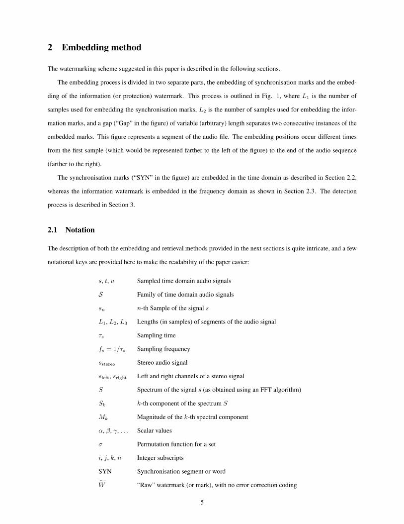
Table 7 compares the robustness of the chosen and the proposed schemes, where the “ODG” column shows the
average ODG obtained for these nine attacks for the six test files. All of these schemes provide similar robustness for
the chosen set of attacks. Note that the robustness results are given in bit error rate (BER) form which is common for
the reported works. For the proposed scheme, the BER is not directly obtained since repeat coding and error correcting
codes are used as detailed above. The BER values displayed in the table for the suggested scheme are 0 when the mark
is recovered (since it is only considered recovered if all bits are correct) and 50% (which is the worst possible value)
when the attack is considered successful (only for the re-sampling 11.025 kHz attack)6, although the real BER value
6Although the re-quantisation to 8 bits attack is able to erase the mark for the “Violin” file, it is just a single case and it removes the mark with
24

would not be so large. This table shows that the robustness of the suggested scheme is comparable to that of recent
audio watermarking systems.
5 Conclusions
A novel efficient blind watermarking scheme for audio with self-synchronisation is presented. This scheme combines
a time domain embedding of the synchronisation marks with a frequency domain embedding of the information mark.
The detection of the synchronisation mark can be implemented efficiently enough to apply the system in real-time
scenarios (such as broadcast monitoring). Furthermore, the time domain synchronisation technique does not produce
the audible clicks which have been detected in some of the methods described in the literature, making the proposed
scheme suitable for applications which require both efficiency and high audio quality. Once the synchronisation mark
is found, the FFT transform is applied to blocks of the audio stream in order to recover the embedded bits of the
information watermark.
The new scheme is shown to provide excellent imperceptibility (around 0.92 on an ODG-based transparency index
normalised in the interval [0, 1]) and robustness results (0.89 also in a [0, 1] range) against typical signal processing
attacks. In addition, the experiments have been performed for long audio files of pop music (of about 2-3 minutes
each) and also for some classical music clips. The method has been compared with other systems in the literature,
showing that it provides similar robustness and capacity results even though the main advantages of the method are its
excellent transparency and efficiency.
There are several directions to further the research presented in this paper. For example, the Reed-Solomon codes
used for error correction might be replaced by other codes which provide better correction results for non-consecutive
errors. Secondly, this watermarking scheme could be implemented in real scenarios for ownership, proof of ownership
or fingerprinting applications. Finally, the suggested scheme might be tested in a real-time application, such as in the
monitoring of (simulated) digital radio or television broadcasts.
Acknowledgement
This work is partially supported by the Spanish Ministry of Science and Innovation and the FEDER funds under the
grants TSI2007-65406-C03-03 E-AEGIS and CONSOLIDER-INGENIO 2010 CSD2007-00004 ARES.
References
[1] LAME Ain’t an MP3 Encoder. http://lame.sourceforge.net/. Last checked on March 11, 2010.
an ODG of −3.81. Thus, such attack has not been considered successful.
25

[2] Opera software by Opticom. http://www.opticom.de/products/opera.html. Last checked on
March 11, 2010.
[3] Nedeljko Cvejic and Tapio Seppanen, editors. Digital Audio Watermarking Techniques and Technologies: Ap-
plications and Benchmarks. IGI Global, 2007.
[4] Jana Dittmann, David Megıas, Andreas Lang, and Jordi Herrera-Joancomartı. Theoretical framework for a prac-
tical evaluation and comparison of audio watermarking schemes in the triangle of robustness, transparency and
capacity. Transactions on Data Hiding and Multimedia Security, Lecture Notes in Computer Science 4300:1–40,
October 2006.
[5] EBU. SQAM - Sound Quality Assessment Material, 2001. http://140.130.175.70/html/mpeg4/
sound.media.mit.edu/mpeg4/audio/sqam/index.html. Last checked on March 11, 2010.
[6] Mehdi Fallahpour and David Megıas. High capacity audio watermarking using FFT amplitude interpolation.
IEICE Electronics Express, 6(14):1057–1063, 2009.
[7] Mingquan Fan and Hongxia Wang. Chaos-based discrete fractional sine transform domain audio watermarking
scheme. Comput. Electr. Eng., 35(3):506–516, 2009.
[8] J.-W. Huang, Y Wang, and Y.-Q. Shi. A blind audio watermarking algorithm with self-synchronization. In
Proccedings of the IEEE International Symposium on Circuits and Systems, volume 3, pages 627–630, 2002.
[9] ITU-R. Recommendation BS.1387. Method for objective measurements of perceived audio quality, December
1998.
[10] Hyunho Kang, Koutarou Yamaguchi, Brian Kurkoski, Kazuhiko Yamaguchi, and Kingo Kobayashi. Full-index-
embedding patchwork algorithm for audio watermarking. IEICE - Trans. Inf. Syst., E91-D(11):2731–2734, 2008.
[11] Hyoung Joong Kim. Intelligent Watermarking Techniques, chapter 8 - Audio Watermarking Techniques. World
Scientific, 2004.
[12] A. Lang. StirMark Benchmark for Audio. http://amsl-smb.cs.uni-magdeburg.de. Last checked
on March 11, 2010.
[13] Andreas Lang, Jana Dittmann, Ryan Spring, and Claus Vielhauer. Audio watermark attacks: from single to
profile attacks. In MM&Sec ’05: Proceedings of the 7th workshop on Multimedia and security, pages 39–50,
New York, NY, USA, 2005. ACM Press.
[14] Zhang Li, Chen Li-min, and Qian Gong-bin. Self-synchronization adaptive blind audio watermarking. In Pro-
ceedings of the 12th International Conference on Multi-Media Modelling, January 2006.
26

[15] Yiqing Lin and W.H. Abdulla. A secure and robust audio watermarking scheme using multiple scrambling and
adaptive synchronization. In Proceedings of the 6th International Conference on Information, Communications
& Signal Processing, pages 1–5, 2007.
[16] Hai-yan Liu, Xue-feng Zheng, and Ying Wang. DWT-based audio watermarking resistant to desynchronization.
In Proceedings of the 7th IEEE International Conference on Computer and Information Technology, CIT 2007,
pages 745–748, October 2007.
[17] Z. Liu and A. Inoue. Audio watermarking techniques using sinusoidal patterns based on pseudorandom se-
quences. IEEE Trans. Circuits and Systems for Video Technology, 13(8):801–812, August 2003.
[18] D. Megıas, J. Herrera-Joancomartı, and J. Minguillon. A robust audio watermarking scheme based on MPEG
1 layer 3 compression. In Communications and Multimedia Security - CMS 2003, Lecture Notes in Computer
Science 2828, pages 226–238, Turin (Italy), October 2003. Springer-Verlag.
[19] D. Megıas, J. Herrera-Joancomartı, and J. Minguillon. Robust frequency domain audio watermarking: a tuning
analysis. In International Workshop on Digital Watermarking - IWDW 2004, Lecture Notes in Computer Science
3304, pages 244–258, Seoul (Korea), November 2004. Springer-Verlag.
[20] D. Megıas, J. Herrera-Joancomartı, and J. Minguillon. Total disclosure of the embedding and detection algo-
rithms for a secure digital watermarking scheme for audio. In ICICS’05: Proceedings of the Seventh Interna-
tional Conference on Information and Communication Security, Beijing, China, December 2005.
[21] No, Really. Rust. http://www.jamendo.com/en/album/7365. Last checked on March 11, 2010.
[22] Belle Arte Quartet. Canon in D – Pachelbel. http://www.classicalmusicva.com/BelleArte/
audio/belle_arte-pachelbel_canon_in_d.mp3. Last checked on March 11, 2010.
[23] Shifa Sun and Sam Kwong. A self-synchronisation blind audio watermarking algorithm. In Proceedings of
the International Symposium on Intelligent Signal Processing and Communication Systems, pages 133–136,
December 2005.
[24] T. Thiede, W. C. Treurniet, R. Bitto, C. Schmidmer, T. Sporer, J. G. Beerends, C. Colomes, M. Keyhl, G. Stoll,
K. Brandeburg, and B. Feiten. PEAQ – The ITU standard for objective measurement of perceived audio quality.
J. Audio Eng. Soc., 48(1-2):3–29, Jan.-Feb. 2000.
[25] Hong Wang, Yi Sun, Ling Lu, and Wenbing Shu. Anti-cropping synchronization audio digital watermark al-
gorithm based on watermark sequence number. In Proceedings of the 8th International Conference on Signal
Processing, volume 4, November 2006.
27

[26] X.-Y. Wang and H. Zhao. A novel synchronization invariant audio watermarking scheme based on DWT and
DCT. IEEE Transactions on Signal Processing, 54(12):4835–4840, December 2006.
[27] Stephen B. Wicker and Vijay K. Bhargava, editors. Reed-Solomon Codes and Their Applications. John Wiley &
Sons, Inc., New York, NY, USA, 1999.
[28] Shaoquan Wu, Jiwu Huang, Daren Huang, and Y.Q. Shi. Efficiently self-synchronized audio watermarking for
assured audio data transmission. IEEE Transactions on Broadcasting, 51(1):69–76, March 2005.
[29] Shijun Xiang, Hyoung Joong Kim, and Jiwu Huang. Audio watermarking robust against time-scale modification
and MP3 compression. Signal Process., 88(10):2372–2387, 2008.
[30] In-Kwon Yeo and Hyoung Joong Kim. Modified patchwork algorithm: a novel audio watermarking scheme.
IEEE Transactions on Speech and Audio Processing, 11(4):381–386, 2003.
28

Title Genre Time # marks ODG TODG
Floodplain Electric folk 3:13 146 0.00 1.00
Stop Payment Electric folk 2:09 99 0.00 1.00
Rust Electric folk 2:33 117 −0.10 0.98
Canon Classical (quartet) 0:55 41 −0.17 0.96
Bass Classical (voice) 0:25 19 −1.07 0.73
Violin Classical (instrument) 0:30 22 −0.55 0.86
Table 1: Transparency results
29

Attack # E # R Detected LUS (sec.) ODG TODG
Marked signal (no attack) 117 117 Yes 1.30 0.00 1.00
Re-quantisation 117 33 Yes 23.43 −1.85 0.54
Re-sampling 22.05 kHz 117 26 Yes 26.04 −1.63 0.59
Re-sampling 11.025 kHz 117 0 No Whole file −3.37 0.16
Additive noise 117 44 Yes 16.92 −3.60 0.10
10% cropping 117 105 Yes 1.62 NA NA
RC Low-pass 117 89 Yes 5.21 −0.21 0.95
Butterworth 117 7 Yes 108.05 −2.58 0.36
MP3 256 kbps 117 109 Yes 2.60 0.00 1.00
MP3 192 kbps 117 92 Yes 7.81 −0.04 0.99
MP3 128 kbps 117 60 Yes 19.53 −0.44 0.89
MP3 112 kbps 117 36 Yes 26.04 −0.69 0.83
MP3 96 kbps 117 13 Yes 52.07 −1.11 0.72
Table 2: Robustness results for the file “Rust”
30

Test file Attack # R (# E) Det. LUS ODG TODG
Floodplain
Re-sampling 11.025 kHz 0 (146) No Whole file −3.39 0.15
Butterworth 7 (146) Yes 156.21 −2.77 0.31
MP3 112 kbps 28 (146) Yes 28.64 −0.84 0.79
MP3 96 kbps 13 (146) Yes 74.20 −1.30 0.68
StopRe-sampling 22.05 kHz 19 (99) Yes 41.66 −1.87 0.53
Re-sampling 11.025 kHz 0 (99) No Whole file −3.38 0.16
PaymentButterworth 6 (99) Yes 106.75 −2.72 0.32
MP3 96 kbps 5 (99) Yes 108.05 −1.30 0.68
Canon
Re-sampling 22.05 kHz 15 (41) Yes 9.11 −0.41 0.90
Re-sampling 11.025 kHz 1 (41) Yes 50.77 −3.26 0.18
Butterworth 5 (41) Yes 27.34 −0.50 0.88
MP3 96 kbps 1 (41) Yes 44.39 −1.26 0.69
Bass
Re-sampling 11.025 kHz 1 (19) Yes 18.92 −2.91 0.27
Re-quantisation 5 (19) Yes 9.11 −3.17 0.21
Butterworth 4 (19) Yes 7.81 −0.67 0.83
MP3 96 kbps 1 (19) Yes 23.43 −1.49 0.63
Violin
Re-quantisation 0 (22) No Whole file −3.81 0.05
Re-sampling 11.025 kHz 0 (22) No Whole file −3.20 0.20
Additive noise 2 (22) Yes 20.83 −3.75 0.06
MP3 96 kbps 4 (22) Yes 14.32 −1.84 0.54
Table 3: Robustness results for the other test files (most damaging attacks)
31

L3 m α ODG TODG # marks Capacity (bps)
512 249 1.1 −0.10 0.98 117 30.73
1024 505 1.1 −0.13 0.97 60 15.94
256 121 1.1 −0.30 0.93 219 57.30
512 252 1.1 −0.50 0.88 117 30.73
512 249 1.25 −1.17 0.71 117 30.73
Table 4: Effect of the tuning parameters for the file “Rust”
32

Scheme Content Sync SNR (dB) Payload (bps)
[8] Short clips Yes 43.0 36
[26] Short clips Yes 43.1 –
[29] SQAM clips No 42.8 2
[7] Song No 30− 45 86
[10] Song No 25 43
Proposed Song + Quartet + SQAM clips Yes 25.70 30.73
Table 5: Comparison of the chosen schemes in terms of SNR and capacity
33

Title GenreProposed [8] [26]
ODG Clicks Tr. ODG Clicks Tr. ODG Clicks Tr.
Floodplain Electric folk 0.00 No Yes −0.31 Yes No −0.05 Yes No
Stop Payment Electric folk 0.00 No Yes −0.61 Yes No −0.11 Yes No
Rust Electric folk −0.10 No Yes −0.67 Yes No −0.15 Yes No
Canon Quartet −0.17 No Yes −0.31 Yes No 0.00 Yes No
Bass Voice −1.07 No Yes −0.05 Yes No 0.00 Yes No
Violin Instrument −0.55 No Yes −0.08 Yes No −0.12 Yes No
Table 6: Transparency comparison for the same capacity (30.73 bps)
34
Attack ODGRobustness (BER %)
Proposed [8] [26] [29] [7] [10]
Re-quantisation −2.14 0 0 0 0 – 0.5
Re-sampling 22.05 kHz −1.10 0 49 0 0 0 1
Re-sampling 11.025 kHz −3.29 ∼ 50 49 1 – 0 –
Additive noise −3.24 0 3 1 0 0 2
10% cropping NA 0 0 0 0 – –
Low-pass filters−0.15 (RC) 0
– –10-15 1 1, 2
−1.60 (But.) (10 kHz) (6-8 kHz) (20 kHz) (12, 8 kHz)
MP3 128 kbps −0.64 0 0 0 0 0 1
MP3 112 kbps −0.93 0 0 0 0 0 –
MP3 96 kbps −1.38 0 – 0 0 0 2
Table 7: Comparison of the chosen schemes in terms of robustness
35

Figure 1: Embedding segments
36
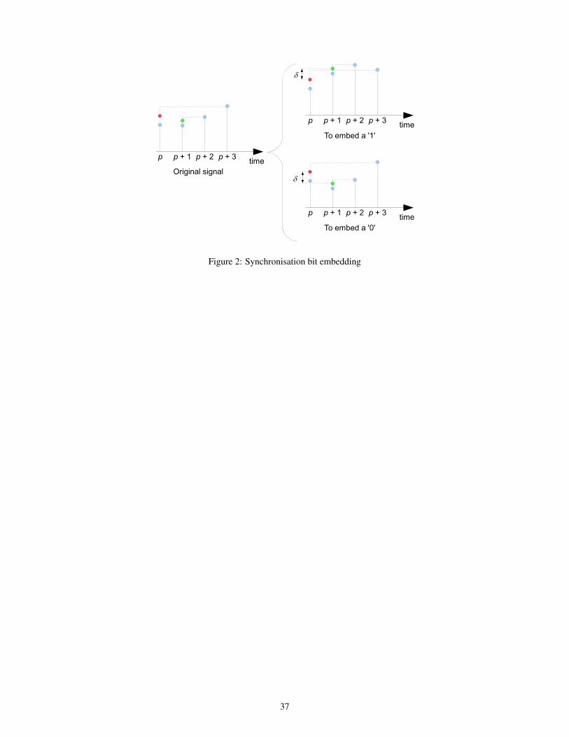
Figure 2: Synchronisation bit embedding
37

0 20 40 60 80 100 120 140 160−0.06
−0.05
−0.04
−0.03
−0.02
−0.01
0
0.01
0.02
0.03
0.04
Sample
Original signal
(a) Original
0 20 40 60 80 100 120 140 160−0.06
−0.05
−0.04
−0.03
−0.02
−0.01
0
0.01
0.02
0.03
0.04
Sample
Proposed scheme
(b) Proposed
0 20 40 60 80 100 120 140 160−0.4
−0.35
−0.3
−0.25
−0.2
−0.15
−0.1
−0.05
0
0.05
0.1
Sample
Huang et al. (2002)
(c) [8]
0 20 40 60 80 100 120 140 160−0.06
−0.05
−0.04
−0.03
−0.02
−0.01
0
0.01
0.02
0.03
0.04
Sample
Wang and Zhao (2006)
(d) [26]
Figure 3: Comparison of the synchronisation schemes
38
Related Documents