CIP-ICT PSP-2011-5 ICT FOR ENERGY EFFICIENCY IN PUBLIC BUILDINGS EDISON_D6.2.1_EDISON_Training_Activities_Description_document_v1.0.doc 1/72 SEVENTH FRAMEWORK PROGRAMME THEME 1- ICT FOR A LOW CARBON ECONOMY AND SMART MOBILITY Project acronym: EDISON Project full title: Energy Distribution Infrastructure for Ssl Operative Networks Grant agreement no.: 297386 (CIP-ICT PSP-2011-5) Grant agreement for: CIP – Pilot Actions EDISON Training Activities Description Document Number of deliverable: D6.2.1 Date of preparation of the deliverable (latest version): 07/01/2015 Date of approval of the deliverable by the Commission: dd/mm/2015 Dissemination Level: PU European Commission – Information Society and Media Directorate – General

Welcome message from author
This document is posted to help you gain knowledge. Please leave a comment to let me know what you think about it! Share it to your friends and learn new things together.
Transcript

CIP-ICT PSP-2011-5 ICT FOR ENERGY EFFICIENCY IN PUBLIC BUILDINGS
EDISON_D6.2.1_EDISON_Training_Activities_Description_document_v1.0.doc 1/72
SEVENTH FRAMEWORK PROGRAMME THEME 1- ICT FOR A LOW CARBON ECONOMY AND SMART MOBILITY
Project acronym: EDISON Project full title: Energy Distribution Infrastructure for Ssl Operative Networks Grant agreement no.: 297386 (CIP-ICT PSP-2011-5) Grant agreement for: CIP – Pilot Actions
EDISON Training Activities Description Document Number of deliverable: D6.2.1 Date of preparation of the deliverable (latest version): 07/01/2015 Date of approval of the deliverable by the Commission: dd/mm/2015 Dissemination Level: PU
European Commission – Information Society and Media Directorate – General

CIP-ICT PSP-2011-5 ICT FOR ENERGY EFFICIENCY IN PUBLIC BUILDINGS
EDISON_D6.2.1_EDISON_Training_Activities_Description_document_v1.0.doc 2/72
R E V I S I O N C H A R T A N D H I S T O R Y L O G
Versions
Version
number When Organisation name Comments
0.1 20/12/2014 VUB First version
0.2 05/01/2015 FUB Updated version
0.3 07/01/2015 VUB Updated version
0.9 07/01/2015 FUB, VUB Updated Version
1.0 07/01/2015 FUB Final version
Deliverable quality review
Date Comments
Steering Committee 07/01/2015
Project Manager 07/012015

CIP-ICT PSP-2011-5 ICT FOR ENERGY EFFICIENCY IN PUBLIC BUILDINGS
EDISON_D6.2.1_EDISON_Training_Activities_Description_document_v1.0.doc 3/72
Executive Summary The first objective is to report on how concepts, technologies and results of the EDISON
project are being communicated to both professionals and non-technical managers having
an interest in this field.
This training tool will enable the above mentioned target groups to understand:
• current and emerging needs in the area of electricity distribution that are on the basis of the
EDISON project;
• how the adopted technologies are useful to develop new services;
• environmental impact of the EDISON solution, especially if compared to existing ones;
• to facilitate on the basis of the results of Pilots user assessment the interaction with the
EDISON technology and technical solutions;
• how to use the stakeholder-based requirements to define the constraints of the EDISON-
based possible services.
The greater part of these aspects has been described through guideline instructions and
web-based multimedia tutorial (off-line help), and all of these tools are available via the
EDISON website.
In addition it has been reported the “cross fertilization” meetings with other EU projects in a
similar domain, and how these meetings helped exchange information, confront and
harmonisation among projects. Finally the participation in Standard Bodies meetings are
shortly reported.

CIP-ICT PSP-2011-5 ICT FOR ENERGY EFFICIENCY IN PUBLIC BUILDINGS
EDISON_D6.2.1_EDISON_Training_Activities_Description_document_v1.0.doc 4/72
T A B L E O F C O N T E N T S
EXECUTIVE SUMMARY ............................................................................................. 3
1. INTRODUCTION ................................................................................................ 7
1.1 Reference documents ........................................................................................ 8
2 OVERVIEW OF THE TRAINING MATERIALS .................................................. 9
2.1 Technical documentation and installation guidelines ......................................... 9
2.1.1 EDISON booklet ................................................................................................................... 9
2.1.2 EDISON installation manual ............................................................................................... 11
2.1.3 EDISON Software tool........................................................................................................ 19
2.2 Tutorials ........................................................................................................... 20
2.3 Interviews ........................................................................................................ 25
2.4 Scientific/technical training material ................................................................. 26
3 INTERACTIONS WITH SIMILAR PROJECTS AND RELATED INITIATIVES 29
3.1 ETSI workshop on Smart M2M Appliances ..................................................... 29
3.1.1 Workshop aim and topics .................................................................................................... 29
3.1.2 oneM2M work areas............................................................................................................ 30
3.1.3 M2M Service Layer Middleware ........................................................................................ 30
3.2 IEEE CASE Conference .................................................................................. 30
3.3 IEEE Online GreenComm 2013 ....................................................................... 31
3.4 IEEE SmartGridConference ............................................................................. 31
4 CONCLUSIONS ............................................................................................... 33
ANNEX – EDISON BOOKLET .................................................................................. 34

CIP-ICT PSP-2011-5 ICT FOR ENERGY EFFICIENCY IN PUBLIC BUILDINGS
EDISON_D6.2.1_EDISON_Training_Activities_Description_document_v1.0.doc 5/72
T A B L E O F F I G U R E S
FIG. 1: TOC OF EDISON BOOKLET ....................................................................................10
FIG. 2: FIRST EXTRACT OF EDISON TUTORIAL 1: FOCUS ON ELECTRICAL
INSTALLATION .............................................................................................................21
FIG. 3: SECOND EXTRACT OF EDISON TUTORIAL 1: FOCUS ON ELECTRICAL
INSTALLATION .............................................................................................................22
FIG. 4: FIRST EXTRACT OF EDISON TUTORIAL 2: FOCUS ON ICT ................................23
FIG. 5: SECOND EXTRACT OF EDISON TUTORIAL 2: FOCUS ON ICT ............................24
FIG. 6: EXAMPLE OF INTERVIEW WITH PROJECT MANAGER DARIO DI ZENOBIO ......25
FIG. 7: EXTRACT OF PAPER 2: EXPLANATION OF ELECTRICAL INSTALLATION ..........28
FIG. 8: EXTRACT OF PAPER 3: EXPLANATION ON ICT AND SOFTWARE ......................27
FIG. 9: HIGHLIGHTS FROM ETSI WORKSHOP BRUSSELS MAY 2014 ............................29
G L O S S A R Y
AC Alternating Current
CFL Compact Fluorescent Lamp
CPC Central Power Control
DC Direct Current
ICT Information and Communication Technology
LED Light Emitting Diode
M2M Machine to Machine
PIR Passive InfraRed
REST Representational State Transfer
RS Remote Station
RSP Relay Switching Panel
SANET Sensor and Actuator Network
SELV Safety Extra Low Voltage
SEP Smart Energy Platform
VUB Vrije Universiteit Brussel

CIP-ICT PSP-2011-5 ICT FOR ENERGY EFFICIENCY IN PUBLIC BUILDINGS
EDISON_D6.2.1_EDISON_Training_Activities_Description_document_v1.0.doc 6/72
P A R T I C I P A N T O R G A N I S A T I O N S
Participant organisation name Short name Country
FONDAZIONE UGO BORDONI FUB Italy
SIELTE SA SIE Romania
TSITALIA TSI Italy
BK TELEMATICS LTD BKT Greece
VRIJE UNIVERSITEIT BRUSSEL VUB Belgium
FONDAZIONE IDIS-CITTÀ DELLA SCIENZA IDIS Italy
COMUNE DI LETTOMANOPPELLO LMP Italy
COMUNE DI MANOPPELLO MNP Italy
COMUNE DI ROCCAMONTEPIANO RMP Italy
SEMPLE & MCKILLOP LTD SMK United Kingdom
ANCITEL SPA ANC Italy
ENEL SOLE S.R.L. ENSO Italy
TRAFFIC OBSERVATION VIA MANAGEMENT
LTD TOM United Kingdom
SOUTHERN HEALTH AND SOCIAL CARE
TRUST SHT United Kingdom

CIP-ICT PSP-2011-5 ICT FOR ENERGY EFFICIENCY IN PUBLIC BUILDINGS
EDISON_D6.2.1_EDISON_Training_Activities_Description_document_v1.0.doc 7/72
1. Introduction
This document will provide the activities performed to make potential interested parties
understand:
• current and emerging needs in the area of electricity distribution that are on the basis of
the EDISON project;
• how the adopted technologies are useful to develop new services;
• environmental impact of the EDISON solution, especially if compared to existing ones;
• how the results of the user assessment are useful to design accessible and
understandable user interaction with the technology.
• how to use the stakeholder-based requirements methodology developed in previous
WPs, to research the complex requirements and constraints for EDISON-based
services.
It also reports on result of interactions with similar projects and related initiatives.

CIP-ICT PSP-2011-5 ICT FOR ENERGY EFFICIENCY IN PUBLIC BUILDINGS
EDISON_D6.2.1_EDISON_Training_Activities_Description_document_v1.0.doc 8/72
1.1 Reference documents
[RD-1]: EDISON Analysis of Best Practices [D2.2.1]
[RD-2]: EDISON hardware & software design [D3.1.1]
[RD-3]: EDISON Sub-systems & LAB Tests Document [EDISON MS5]
[RD-4]: EDISON Pilot Description & EDISON model [D2.1.1]
[RD-5]: EDISON BOOKLET (Annex to D5.1.1)
[RD-6]: Di Zenobio Dario, De Caro Niccolo, Thielemans Steffen, Steenhaut Kris “EDISON:
An Innovative Lighting Architecture Facilitating Building Automation”, IEEE
International Conference on Automation Science and Engineering (CASE 2013),
Madison Wisconsin USA, August 17-21 2013, pp: 237 - 242, eds: Michael Yu Wang,
published by: IEEE Explore, ISBN-ISSN: 978-1-4799-1515-6, 2013
[RD-7]:Celidonio M, Di Zenobio D, Fionda E, Pulcini L, Sergio E: “The EDISON Project:
Enhanced Energy Saving Solution for Lighting using DC Power Supply”; IEEE
Online conference on green communications, 29-31 October 2013.
[RD-8]:Celidonio M. ; Fionda E.;Pulcini L.;Sergio E. ; Di Zenobio D. “A centralised DC power
supply solution for LED lighting networks.”; Energy Conference (ENERGYCON),
2014, Pages: 1137 – 1143, DOI: 10.1109/ENERGYCON.2014.6850566; IEEE
Explore 2014.
[RD-9]:Thielemans Steffen, Di Zenobio Dario, Steenhaut Kris: “Lighting In The Building: A
DC Smart Grid”, IEEE International Conference on Smart Grid Communications,
Venice November 2014 pp: 157 - 162, 2014.
[RD-10]:Jörg Swetina, Guang Lu, Philip Jacobs, François Ennesser, and Jaeseung Song
“Toward A Standardized Common M2m Service Layer Platform: Introduction to
OneM2M” IEEE Wireless Communications • June 2014, Pp20-26

CIP-ICT PSP-2011-5 ICT FOR ENERGY EFFICIENCY IN PUBLIC BUILDINGS
EDISON_D6.2.1_EDISON_Training_Activities_Description_document_v1.0.doc 9/72
2 Overview of the training materials
2.1 Technical documentation and installation guidelines
2.1.1 EDISON BOOKLET
The main goal of the EDISON booklet is to give evidence of any practical aspect handled in
the implementation of the EDISON solution in the Pilot actions realized in the context of the
project, in order to provide all the criteria and the guidelines for replicating the solution
implementation in any category of building, considering the different environmental
constraints, planning alternatives, lighting and energy requirements, which the building might
present.
To this aim, an index of the main topics discussed in the booklet (see Annex 1) is provided:
1. the main features of the basic components of the EDISON platform (Section 2 of the
booklet.
2. the technical alternatives appropriate to the nature and structural characteristics of the
building of interest, considering all the constraints deriving from the existing electrical
infrastructure in retrofitting action (Section 3 of the booklet)
3. regulatory and installing matters, such as prerequisites, cabling details, electrical plant
configuration, etc. to cope with in EDISON implementation (Section 4 of the booklet)
4. advantage of the experiences gained in the case studies, that address both retrofitting
and new installations, reported in Section 5.
Fig.1 shows the table of contents of the EDISON booklet.

CIP-ICT PSP-2011-5 ICT FOR ENERGY EFFICIENCY IN PUBLIC BUILDINGS
EDISON_D6.2.1_EDISON_Training_Activities_Description_document_v1.0.doc 10/72
Fig. 1: ToC of EDISON booklet

CIP-ICT PSP-2011-5 ICT FOR ENERGY EFFICIENCY IN PUBLIC BUILDINGS
EDISON_D6.2.1_EDISON_Training_Activities_Description_document_v1.0.doc 11/72
2.1.2 EDISON INSTALLATION MANUAL
The main goal of the EDISON installation manual is to give technical and safety guidelines
for technicians in order to be able to install the EDISON solution in a safe and optimal way. It
draws the attention on safety issues.
NOTE: EDISON Smart Energy Platform (SEP) includes components, communications
system, and auxiliary ports, which operate in safety extra-low voltage (SELV) circuits. To find
out which cable to use with which interface, see the components and their integrating
procedure guide (Sections 2,4 Booklet).
2.1.2.1 SITE PREREQUISITES AND INSTALLATION
For the safe installation and operation of any EDISON device (CPC, RS, lamp, fixture,
sensor, actuator), ensure that the site is properly prepared before beginning the hardware
installation.
The following information will help you ensure that the site is properly prepared:
a) Check at the Main Switch Board the lighting electrical network is completely
separated from the appliances network.
b) Check the power at your site, in the Main Switch Board, to ensure that you are
receiving clean power (free of spikes and noise). Install a power conditioner if
necessary.
c) Choose a site for the electronic parts of EDISON solution that maintains an ambient
temperature of 0 – 40°C (32 – 104°F). Any device is intended for use in a normal
office environment. For more extreme conditions, verify that temperature, humidity,
and power conditions meet the specifications for each EDISON device, reported on
the box of the component. For other specifications, see the hardware guide of the
device.
d) The EDISON platform relies on the building’s safety features for protection against
short-circuit, over-current and earth (grounding) fault, for the AC interface to the main
network. Ensure that the building’s safety features are properly rated for the CPC
Master requirements.
e) Ensure that the device is installed in a secure location where access to the device is
limited to authorized personnel.
In case PV or alternative energy DC source are used, the steps b and d could be avoided.

CIP-ICT PSP-2011-5 ICT FOR ENERGY EFFICIENCY IN PUBLIC BUILDINGS
EDISON_D6.2.1_EDISON_Training_Activities_Description_document_v1.0.doc 12/72
2.1.2.2 GENERAL INFORMATION ABOUT INSTALLATION.
For the professional installation and connection, please consult the relevant laws and
regulations. The requirements of the safety regulations of electrical engineering, the
local employer’s liability insurance association and the international standard IEC 60204 are
to be taken into full consideration.
Mounting location
The EDISON modules must be mounted in control cabinets which is sealed to at least IP54.
The units must be snapped onto a 35 mm mounting rail, which is grounded, as the part of the
circuit operating at 220VAC, the DC circuits must not be grounded. If it is used outside of a
control cabinet a housing with a protection category of IP54 and a mounting rail capability is
recommended.
Cable and wires
The wires of the DC circuits (in the lighting infrastructure, CPC, RS, etc.) must be securely
separated and guided away from the wires of the AC section.
Supply voltage
To safeguard the controller, the DC terminal should be protected with an external fuse and
automatic circuit breaker . The controller and the components should be offline before
beginning the installation.
The supply voltage must conform to the requirements of EN 60204-1, it must bridge a 20 ms
interruption of the supply network. When considering the supply voltage, it must be SELV
(Safety-Extra-Low-Voltage)
NOTE: it is recommended to place any EDISON smart device on a desktop or wall-mount it
in a rack, box, according to its intended use as specified in the hardware guide for the
device.
Both the location of the chassis and the layout of your equipment rack or wiring room are
extremely important for proper system operation.
Devices placed too close together will cause inadequate ventilation and render areas of the
device inaccessible for system maintenance during any system malfunctions or shutdowns.
When planning site lighting layout and equipment locations, follow the precautions described
below to help avoid equipment failures and reduce the possibility of environmentally caused

CIP-ICT PSP-2011-5 ICT FOR ENERGY EFFICIENCY IN PUBLIC BUILDINGS
EDISON_D6.2.1_EDISON_Training_Activities_Description_document_v1.0.doc 13/72
shutdowns. If you are experiencing shutdowns or unusually high errors with your existing
equipment, these precautions might help to isolate the cause of the failures and prevent
future problems:
• Ensure that the room in which systems operate has adequate air circulation. Electrical
equipment generates heat. Natural air temperature might not be sufficient to cool the
equipment to acceptable operating temperatures without an additional ventilation
system (see the Pilot report of VUB restaurant, etc.).
• Choose a site with a dry, clean, well-ventilated, and air-conditioned area.
2.1.2.3 WARNINGS
• Restricted Access Area Warning
Only trained and qualified personnel should install or replace the EDISON devices.
Any device is intended for installation in restricted access areas.
A restricted access area is an area to which access can be gained only by service
personnel through the use of a special tool, lock and key, or other means of security,
and which is controlled by the authority responsible for the location.
• Lighting Activity
Do not work on the devices, or connect or disconnect any device, during lighting
activity.
• Fire Suppression and Fire Suppression Equipment
In the event of an electrical hazard or fire, first turn off power to the equipment at the
source. Then use a Type C fire extinguisher to extinguish the fire. Type C fire
extinguishers use noncorrosive fire retardants such as carbon dioxide (CO2) and
Halotron™ and are most effective for suppressing electrical fires. Type C fire
extinguishers displace the oxygen from the point of combustion to eliminate the fire.
For extinguishing fire on or around equipment that draws air from the environment for
cooling, use this type of inert oxygen displacement extinguisher instead of an
extinguisher that leaves residue on equipment.
2.1.2.4 EDISON SENSOR/ACTUATOR NETWORK (SANET) INSTALLATION MANUAL
This manual reports some information about technical aspects and installation of sensors
and actuators that can be applied in the EDISON platform.

CIP-ICT PSP-2011-5 ICT FOR ENERGY EFFICIENCY IN PUBLIC BUILDINGS
EDISON_D6.2.1_EDISON_Training_Activities_Description_document_v1.0.doc 14/72
A wide selection of occupancy and vacancy sensors, commonly referred to as "motion
sensors" or "motion light sensors" for commercial and residential applications, could be used
in EDISON solution, as mentioned in the booklet. These state-of-the-art devices use passive
infrared, ultrasonic or a combined multi-sensing technology. From wall and ceiling mount to
wall switch (wired and wireless as well), the commercial motion sensors enhance
convenience, security and provide smart energy saving solutions for both indoor and outdoor
use. It could be useful to recall the main features and functionalities of the lighting sensors
(presence and daylight) compliant with EDISON solution.
It should be noticed that with the presence detectors every option is open for energy-efficient
and intelligent lighting control. In addition to classic use for lighting control in offices, corridors
and public buildings, it can be also controlled heating and air-conditioning based on
presence.
This is how EDISON saves on energy and considerably reduce CO2 emissions. Presence
detectors react to the smallest of movements and measure room brightness at the same
time. If no more movement is detected, or an individually set brightness value is exceeded,
the presence detector automatically switches off the signal-relay (Ohmic contact).
Some useful tips and advice on the selection, installation and set-up of presence/luminosity
(often all in one) detectors are listed below:
.
a) Technology: How does a presence detector work?
b) Light measurement: Real daylight measurement, mixed light measurement and
constant light control
c) Application: Which is the right presence detector?
d) Installation: Correct installation of presence detector
e) Set-up: Correct setting of presence detector
f) Further information on presence detectors
a) Technology: How does a presence detector work?
Presence detectors – also referred to as PIR (Passive InfraRed) – work according to the
same principle as . The detectors log thermal radiation in their environment or in their
detection area. If thermal radiation is detected in the monitored area in the event, for
example, of a person approaching the presence detector, the presence detector converts
them into a measureable, electric signal and the signal-relay is switched on.
The difference between motion and presence detectors is in the sensor sensitivity. Presence
detectors have clearly more sensitive sensors than motion detectors and log the smallest of
movements. The sensitive sensors divide the detection area of a presence detector

CIP-ICT PSP-2011-5 ICT FOR ENERGY EFFICIENCY IN PUBLIC BUILDINGS
EDISON_D6.2.1_EDISON_Training_Activities_Description_document_v1.0.doc 15/72
evenly into up to 1000 areas. Like a chessboard, the areas are pulled through the entire
detection area. Even minor changes in the thermal image, such as typing on the keyboard in
the large office area, are logged. A motion detector, on the other hand, only reacts to larger
changes in the thermal image and is therefore primarily only suitable for being used outdoors
or indoor with the help of some software tool (as in EDISON). Another difference between
motion and presence detectors is the light measurement. A motion detector measures
brightness once if the light is switched on because of a movement. If it continues to log
movement, e.g. in the morning in an office, the light remains switched on although daylight
would have been sufficient and the set brightness value has long since been
exceeded. Contrary to this, the presence detectors permanently measure the brightness: If
an individually set brightness value is exceeded, the presence detector switches off - even if
it detects movement. Apart from energy costs, this also saves on a lot of CO2.
In addition to the conventional 230 version, presence detectors are also available as 24
VDC, 12 VDC version (both usable in EDISON) or as KNX presence detector.
b)Light measurement
The lighting control with presence detectors based, in part, on the logged movements and on
the other on the light measurement. Presence detectors permanently measure the brightness
in the room. Through such permanent light measurement the presence detector is in a
position not only to switch on signal-relay when there is not enough daylight, but also to
switch off again when there is sufficient daylight. It sounds very easy, in fact the presence
detector must be able to assess, when artificial light is switched on, whether after switching
off there is enough daylight. There are two different methods available: "Real daylight
measurement" and "Mixed light measurement".
Mixed light measurement
When measuring mixed light the presence detector measures the total between artificial light
and daylight. To switch off the artificial light when there is increasing daylight at the right
moment, the presence detector must know the proportion of artificial light. This value can be
learned by the detector automatically by constantly analyzing the lighting switching
processes in the room. This enables it to calculate the current daylight intensity at any time
from the total measured brightness. The advantage of mixed light measurement is that it
works with every light source: LEDs, halogen and fluorescent lamps can be used. The mixed
light measurement is the basis for the constant light control. Typical application
fields: production buildings where a specific brightness level is legally stipulated.

CIP-ICT PSP-2011-5 ICT FOR ENERGY EFFICIENCY IN PUBLIC BUILDINGS
EDISON_D6.2.1_EDISON_Training_Activities_Description_document_v1.0.doc 16/72
Constant light control
When measuring mixed light, the presence detector constantly measures the total daylight
and artificial light. It adjusts the desired brightness value from these two light sources. On a
misty or rainy morning the available daylight is less and the proportion of artificial light is
selected to be higher by the presence detector to reach the desired brightness level in the
room. If the sun breaks through over the course of the morning and there is increased light
through the windows, the presence detector reduces the proportion of artificial light. The
brightness level in the room therefore remains constant, regardless of the incidence of
daylight.
c) Application: Which presence detector is the right one?
When choosing the right presence detector the use in the room plays a decisive role: is it
a "lounge with seated persons" or a "transit area with walking persons" that is to be
monitored?
Seated activities: Presence detector for ceiling mounting
A ceiling mounted presence detector is suitable for an office, a classroom or a conference
room. From the ceiling the presence detector has an "unobstructed view" of everyone and
their movement. Since the distance between people and the presence detector is
limited throughout the entire detection area there is an equally high detection sensitivity.
Walking movements: Presence detector for wall mounting
For the detection of walking persons in corridors or hallways presence detectors for wall
mounting are ideal with a detection area of 180° or a ceiling model with far-reaching
detection areas. With the wall mounting the detection areas are transmitted horizontally in
the room and expand a considerable distance. This means that even walking movements
diagonal to the presence detector at a distance can be captured. If someone goes straight up
to the presence detector the sensitivity is reduced.
d) Installation: correct installation of presence detector
The following points should be taken into account during installation to enable optimum
functionality and avoiding sources of interference:
Anything that can limit the view of the presence detector should be avoided: e.g. hanging
lights, partitions, shelves or even large plants.
Sudden temperature changes in the environment of the presence detector caused by the
switching on or off of fan heaters or fans simulate movement.

CIP-ICT PSP-2011-5 ICT FOR ENERGY EFFICIENCY IN PUBLIC BUILDINGS
EDISON_D6.2.1_EDISON_Training_Activities_Description_document_v1.0.doc 17/72
Lights which are coming on or going off in the vicinity of the detection area (e.g. light bulbs
and halogen lamps at a distance of <1 m) simulate movement and can lead to incorrect
switchings.
Automatically moving objects such as machines, robots etc. simulate movement signals
(possible temperature differences e.g. watch robots or similar.)
Objects which are slow to heat up do not compromise the operation of the presence detector:
Heating radiators (lateral distance from lines and radiators > 0.5 m),
Room air-conditioning systems provided that warm incoming air is not directed at the
presence detector,
Sunlit surface
e) Set up: Correct setting of presence detector
If the presence detector is installed it is possible to proceed to adjust the lux values. This is
carried out using a potentiometer on the device. Some presence detectors can also be easily
set and corrected from the ground via remote control. Since "too dark" or "too light" varies
according to personal perception, the setting of the correct lux value individually is very
different. Here is a short summary of different light scenarios and their lux values:
Bright sunny day 100,000 lx
Overcast summer day 20,000 lx
In the shade in the summer 10,000 lx
Operating theatre 10,000 lx
Overcast winter's day 3,500 lx
TV studio lighting 1,000 lx
Office/room lighting 500 lx
Corridor lighting 100 lx
Street lighting 15 lx
Candle at a distance of approx. 1
meter
1 lx
Full moon 0,25 lx
Clear night sky (new moon) 0,001 lx
f) Further information on presence detectors
The sensors are usually available as Automatic-ON (occupancy) or Manual-ON (vacancy)
models. In EDISON only automatic-ON sensors are used.
AUTOMATIC–ON OPERATION (Occupancy Sensors)

CIP-ICT PSP-2011-5 ICT FOR ENERGY EFFICIENCY IN PUBLIC BUILDINGS
EDISON_D6.2.1_EDISON_Training_Activities_Description_document_v1.0.doc 18/72
Occupancy sensors switch goes ON automatically when motion is detected. This information
is sent to the RS board (Arduino) that switch the lights ON as long as the device detects
activity in the sensor zone. Lights may also be switched OFF at any time by manually
pressing the Aut/Man selector.
For the aspects regarding this installation manual it is important to know that the sensor
should have:
- Screw terminals for easier installation
- Variety of models for control of LED, CFL, Incandescent, Halogen, Fluorescent ballast
or Motor loads could be used.
- 180° Field of View, up to 900 sq. ft. coverage to make these devices suitable for use in
large areas such as basements, garages and living rooms
- Low profile design blends in with walls for a discreet appearance
- Ambient light override (optional) prevents occupancy sensors from switching ON when
there is ample natural sunlight
- Adjustable delayed OFF time which can be set for 30 seconds, 5 minutes, 15 minutes
or 30 minutes (step by step) or from 10sec to 30 min. continuously for effective
energy management
- Neutral not required for EDISON technical compatibility.
- IPV05, IPV02 Compliant.
- Switching technology: Relay Sensor – IPS02 / IPV02 / IPS05 / IPV05
- Single pole only
- Relay-based sensor for reliable switching
- No neutral required for ease of installation in homes where neutral is not available or,
as in EDISON, only 2 supply wires are used
- No Ground required for operation
About the other features, normal ranges are acceptable (Operating Temperature 0°C to
40°C, Relative Humidity 20% to 90% non-condensing, Storage Temperature -10°C to 85°C).
About the daylight sensor when separated from the presence: technical general
characteristics as above; normally it could be operated under software control tool (as in
EDISON). See further sensor features reported in the EDISON booklet.
About other sensors devoted to services different from lighting or presence control, their
characteristics depend on the service they are devoted to.

CIP-ICT PSP-2011-5 ICT FOR ENERGY EFFICIENCY IN PUBLIC BUILDINGS
EDISON_D6.2.1_EDISON_Training_Activities_Description_document_v1.0.doc 19/72
2.1.3 EDISON SOFTWARE TOOL
This section explains how the software has to be configured and loaded on the different
components. A customized firmware on each Remote Station, depending on the pilot
specifications (being the number and type of sensors and actuators different in each site),
must be developed.
How to proceed:
If not yet installed,
1) install the Arduino IDE software from the provided CD/USB or from www.arduino.cc.
This guide is based on Arduino v1.0 but is likely compatible with more recent versions.
The required drivers for the Arduino devices are also provided in this installation;
2) copy the required libraries, provided on CD/USB, to the Arduino IDE software
installation. These libraries contain critical code required for compiling the EDISON RS
firmware. The typical Arduino installation path is: “c:/Program Files
(x86)/Arduino/libraries”;
3) open the Arduino IDE software and navigate to File -> Open in order to open the
desired Arduino sketch (source code). Multiple example sketches are available for
typical EDISON pilot installations. In case an EDISON installer has made the
installation, the used Arduino sketches should be provided on the CD/USB;
4) make the required changes in the sketch to match the exact EDISON pilot
configuration. This configuration includes among others the type of sensors and
actuators, the pin layout, Modbus address, etc. Modification of this configuration is
relatively easy due to the modular structure. See the examples for further information
which component has which function.
Once the configuration is completed it is time to compile the modified firmware which can be
done by Sketch -> Verify/Compile. In case of an error, either the required EDISON libraries
are not installed correctly in the Arduino IDE, or there is an error due to incorrectly modifying
the sketch.
The final step is to upload the firmware to the Arduino board. Attach an Arduino board
through USB with the computer and open the Arduino IDE. Select the corresponding serial
port via the menu Tools -> Serial port. Furthermore make sure that Tools -> Board is set to
Arduino. We have now configured the IDE to communicate with the Arduino board.
Upload the firmware via File -> Upload. In case there is an error, it is likely due to the
selection of a wrong serial port, or due to the lack of the (correct) drivers.

CIP-ICT PSP-2011-5 ICT FOR ENERGY EFFICIENCY IN PUBLIC BUILDINGS
EDISON_D6.2.1_EDISON_Training_Activities_Description_document_v1.0.doc 20/72
2.2 Tutorials
Two tutorials are available on the project’s web site. The first one introduces the EDISON
concept and explains the advantages of the solution in terms of cost and energy efficiency. It
has a focus on the electrical installation aspects. It also discussed the communication and
ICT issues.

CIP-ICT PSP-2011-5 ICT FOR ENERGY EFFICIENCY IN PUBLIC BUILDINGS
EDISON_D6.2.1_EDISON_Training_Activities_Description_document_v1.0.doc 21/72
Fig. 2: First extract of EDISON tutorial 1: focus on Electrical installation

CIP-ICT PSP-2011-5 ICT FOR ENERGY EFFICIENCY IN PUBLIC BUILDINGS
EDISON_D6.2.1_EDISON_Training_Activities_Description_document_v1.0.doc 22/72
Fig. 3: Second extract of EDISON tutorial 1: focus on Electrical installation

CIP-ICT PSP-2011-5 ICT FOR ENERGY EFFICIENCY IN PUBLIC BUILDINGS
EDISON_D6.2.1_EDISON_Training_Activities_Description_document_v1.0.doc 23/72
Fig. 4: First extract of EDISON tutorial 2: focus on ICT

CIP-ICT PSP-2011-5 ICT FOR ENERGY EFFICIENCY IN PUBLIC BUILDINGS
EDISON_D6.2.1_EDISON_Training_Activities_Description_document_v1.0.doc 24/72
Fig. 5: Second extract of EDISON tutorial 2: focus on ICT
CIP-ICT PSP-2011-5 ICT FOR ENERGY EFFICIENCY IN PUBLIC BUILDINGS
EDISON_D6.2.1_EDISON_Training_Activities_Description_document_v1.0.doc 25/72
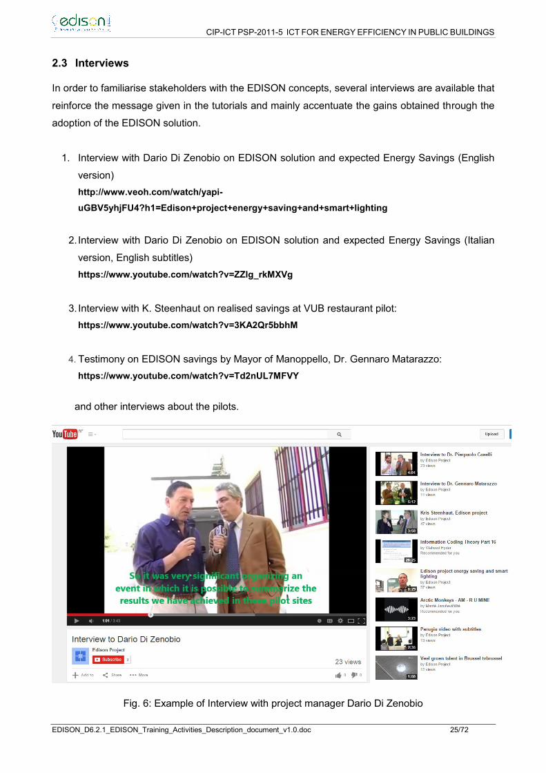
2.3 Interviews
In order to familiarise stakeholders with the EDISON concepts, several interviews are available that
reinforce the message given in the tutorials and mainly accentuate the gains obtained through the
adoption of the EDISON solution.
1. Interview with Dario Di Zenobio on EDISON solution and expected Energy Savings (English
version)
http://www.veoh.com/watch/yapi-
uGBV5yhjFU4?h1=Edison+project+energy+saving+and+smart+lighting
2. Interview with Dario Di Zenobio on EDISON solution and expected Energy Savings (Italian
version, English subtitles)
https://www.youtube.com/watch?v=ZZlg_rkMXVg
3. Interview with K. Steenhaut on realised savings at VUB restaurant pilot:
https://www.youtube.com/watch?v=3KA2Qr5bbhM
4. Testimony on EDISON savings by Mayor of Manoppello, Dr. Gennaro Matarazzo:
https://www.youtube.com/watch?v=Td2nUL7MFVY
and other interviews about the pilots.
Fig. 6: Example of Interview with project manager Dario Di Zenobio

CIP-ICT PSP-2011-5 ICT FOR ENERGY EFFICIENCY IN PUBLIC BUILDINGS
EDISON_D6.2.1_EDISON_Training_Activities_Description_document_v1.0.doc 26/72
2.4 Scientific/technical training material
To get a scientific description of the EDISON solution, its strengths and unique features, 4
technical scientific papers are available and a fifth one will be submitted.
Paper 1 [RD-6] introduces the EDISON approach in a general way and discusses the advantages
compared to other solutions.
Paper 2 [RD-9] again summarizes the unique features of the EDISON solution and shows which
services are made available through the EDISON platform. It introduces the four layered structure
of the Edison platform which consists of a Sensing and Actuating layer and SANET (Sensing and
Actuating Network), A networking layer (Ethernet, PowerLAN, WIFI etc…), a service layer
(exposing the different services offered by the EDISON platform) and an Application layer with
APIs offered to the end-user (e.g. building manager). The interfacing with the EDISON sensor and
actuating/measurement services is done through a RESTful interface; meaning that the
sensors/actuators are reachable through an HTTP like web interface. REST stands for
Representational State Transfer. (It is sometimes spelled "ReST") It relies on a stateless, client-
server, cacheable communications protocol -- and in virtually all cases, the HTTP protocol is
used. REST is an architecture style for designing networked applications.
Paper 3 and 4 [RD-7, RD-8] discuss the overall architecture of the EDISON solution focusing on all
the electrical components and the ICT components and the way they are put together to realize the
EDISON platform.
Paper 5 has been prepared and will be submitted to IEEE consumer electronics and will focus on
the realization of the SANET and its integration in the EDISON solution.

CIP-ICT PSP-2011-5 ICT FOR ENERGY EFFICIENCY IN PUBLIC BUILDINGS
EDISON_D6.2.1_EDISON_Training_Activities_Description_document_v1.0.doc 27/72
Fig. 7: Extract of paper 2: Explanation on ICT and software

CIP-ICT PSP-2011-5 ICT FOR ENERGY EFFICIENCY IN PUBLIC BUILDINGS
EDISON_D6.2.1_EDISON_Training_Activities_Description_document_v1.0.doc 28/72
Fig. 8: Extract of paper 3: explanation of electrical installation

29
3 Interactions with similar projects and related initiatives
3.1 ETSI workshop on Smart M2M Appliances
3.1.1 WORKSHOP AIM AND TOPICS
The ETSI workshop on Smart M2M Appliances took place on 27 & 28 May 2014 in Brussels. The
workshop was attended by K. Steenhaut and project leader D. Di Zenobio.
This workshop is important to understand in which way the standardisation of the semantics for a
service based (RESTfull) approach is going to evolve.
This workshop allowed us to discuss with manufacturers and solution providers for smart building
and smart appliances. The talk given by Manuel Díaz Rodriguez entitled “Costs of connecting
appliances in EEBuildings” proposed several approaches amongst which an approach similar to
EDISON was considered a good option.
Fig. 9: Highlights from ETSI workshop Brussels May 2014
( source: http://www.etsi.org/news-events/events/760-2014-05-dg-connect-etsi-workshop-on-smart-appliances )
The ETSI M2M workshop vision is well summarized in the abstract of [M2M]:
“At present, most M2M solutions in different industries use proprietary systems that often comprise
all layers, from physical to application, to provide their specialized M2M services to customers.
These proprietary systems make it difficult to extend systems to support new services, integrate
new data, and interoperate with other M2M systems. This issue motivated various standard
organizations to establish a new partnership project, the “oneM2M Global Initiative,” to
standardize a common M2M service layer platform for globally applicable and access-independent
M2M services.”

30
On July 24, 2012 seven of the world’s leading ICT Standards Development Organizations (SDOs)
launched a new global organisation: the oneM2M partnership project: http://www.oneM2M.org
oneM2M is working to unify the Global M2M Community, by enabling the federation and
interoperability of M2M systems, across multiple networks and topologies. A global standard
across various industry verticals is necessary to ensure easier use of M2M technology, data
interoperability, and efficient development of M2M systems.
It is important to be aware of this evolution, in particular for allowing the EDISON RESTfull API to
be translated into the core standard for M2M that is under development. More interesting details
can be found in [RD-10].
3.1.2 ONEM2M WORK AREAS
WG1 – Requirements
• Input accepted on more than 100 service requirements
WG2 – Architecture
• Distilling service‐layer architectural options
WG3 – Protocols
• Assessing protocols for service layer, and interoperability
WG4 – Security
• Ensuring Security and Privacy aspects are considered
WG5 – Management & Semantics
• Providing device management; Working on semantic library
3.1.3 M2M SERVICE LAYER MIDDLEWARE
Supporting secure end-to-end data/control exchange between M2M devices and customer
applications by providing functions for remote provisioning & activation, authentication,
encryption, connectivity setup, buffering, synchronization, aggregation and device
management. It is a software layer that:
sits between M2M applications and communication HW/SW that provides data transport
normally rides on top of IP
provides functions that M2M applications across different industry segments
3.2 IEEE CASE Conference
The IEEE CASE conference took place in Madison (Wisconsin-US) from 17th till 20th of August
2013.

31
The IEEE CASE conference is the flagship conference of IEEE Robotics and Automation Society.
The conference aims to bring together researchers in automation from both industry and
academia, together with industrial practitioners, to present and discuss the latest advances and
developments in automation science and engineering.
The IEEE CASE conference was attended by K. Steenhaut and project leader D. Di Zenobio who
presented the Edison project [RD-6].
3.3 IEEE Online GreenComm 2013
IEEE OnlineGreenComm Conference was held from 3 to 6th of November 2014. The Conference
was completely online and covered a wide spectrum of research subjects, including green
methodologies and architectures for communication technologies, communication technologies as
enablers for green solutions, energy efficient in Smart Grid comunications and energy
management.
The Information and Communications Technology sector (ICT) is one of the sectors with the
highest potential to reduce the growing worldwide electricity consumption if appropriate measures
are taken in a timely manner. IEEE OnlineGreenComm addressed this challenge not only from a
technical perspective, but adopted the philosophy of an integrated online approach where online
conferencing complemented the already established processes for online paper handling and
publication. In contrast to physical attendance and in view of the technical subjects addressed by
IEEE OnlineGreenComm, this integrated conferencing philosophy provided a more suitable
approach from an ecological point of view in which “energy efficiency is discussed energy-
efficiently”.
Massimo Celidonio from FUB, during this Conference, presented a paper entitled: “The EDISON
Project: Enhanced Energy Saving Solution for Lighting using DC Power Supply” [RD-7] mainly
focused on the innovative solution of using DC power supply for the lighting infrastructure.
3.4 IEEE SmartGridConference
This IEEE SmartGridComm Conference on Smart Grid Communication was held in Venice from
from 3 to 6th of November 2014. This event provided a forum to discuss all aspects that are
relevant to smart grid communication and information technologies, bringing together researchers
and practitioners from academia, industry, and government institutions, with backgrounds in
communication, energy, control, signal processing, and information systems to exchange ideas,
explore enabling technologies, discuss innovative designs, and share field trial experiences and
lessons learned. http://sgc2014.ieee-smartgridcomm.org/

32
As summarised on the above mentioned website the latest evolutions in the context of ICT for
smart grids are being discussed:
“The evolution of today’s electricity grids into smart grids is a key element for the sustainable
economic, environmental and societal growth worldwide. The migration to smarter grids requires
the integration and exploitation of information and communication technologies. However, it is not
obvious which communication technologies will be integrated into electricity grids and in what way.
Communication systems need to be seen as part of a larger system of systems, including in
particular energy, control, and information processing systems to support two-way energy flows,
the automatic management of power outages, the integration of renewable energy sources and
allowing the consumers to play an active role in energy production and consumption. The overlap
of disciplines is part of the specific challenge and appeal of smart grid communications research
and development.”
Steffen Thielemans (VUB) presented the EDISON idea and the obtained ICT contribution in the
energy savings, together with project leader Dario Di Zenobio [RD-9]. Some suggestions from the
audience (e.g. on automatic configuration) are being taken into account.

33
4 Conclusions
The training material available in relation to the EDISON project is devoted to several types of
audiences.
The stakeholders who just want to have a global idea on the implementation effort/cost and the
benefits in terms of energy usage can concentrate on the EDISON leaflets, flyers and the
interviews.
The stakeholders who want a deeper technical insight in the functioning of the solution can consult
the tutorials and the EDISON booklet. For a deeper study, they can consult the technical/scientific
papers published on the project.
Technicians who will be responsible for implementing EDISON at their premises must consult,
apart from the present training manual, the booklet together the above mentioned installation
guidelines dealing with electrical ICT and software installation.
The EDISON project team has linked with several initiatives on standardization from physical level
till application level. Obviously the training activity has been complementary to a full dissemination
the project idea and results. In any meeting further than just presenting the EDISON solution, on
the basis of results, documentation a strong exchange of information took place. Vigorously any
partner has supported the solution and has provided to interested audience all the general
technical information, by illustrating the advantages and benefits. On the basis of such an
experience and obviously the one matured in the pilots activity, it was possible to summarize in a
document the most important indications for implementing the EDISON solution and to highlight
the critical parts of the platform implementation.
This variagated activity has requested, apart from the mandatory involvement of the partners
managing the training task, the collaboration of all the other partners as well and mainly of the
Project Manager even not planned in the DoW.

34
ANNEX – EDISON Booklet

35
SEVENTH FRAMEWORK PROGRAMME THEME 1- ICT FOR A LOW CARBON ECONOMY AND SMART MOBILITY
Project acronym: EDISON Project full title: Energy Distribution Infrastructure for Ssl Operative Networks Grant agreement no.: 297386 (CIP-ICT PSP-2011-5) Grant agreement for: CIP – Pilot Actions
Guidelines Booklet
Date of preparation of the document (latest version): 09/10/2014
European Commission – Information Society and Media Directorate - General

36
1 Introduction
The main goal of the document is to give evidence of any practical aspect handled in the
implementation of the EDISON solution in the Pilot actions realized in the context of the project, in
order to provide all the criteria and the guidelinesfor replicating the solution implementation in any
category of building, considering the different environmental constraints, planning alternatives,
lighting and energy requirements, which the building might present.
To this aim, after a brief overview about the main features of the basic components of the EDISON
platform in section 2, the section 3 describes the technical alternatives appropriate to the nature
and structural characteristics of the building of interest, also taking advantage from the experiences
gained in the case studies reported in section 5, referred to the most representative project Pilots.
Finally, in section 4 are gathered both regulatory and installing matters (prerequisites, cabling
details, configuration, etc.).

37
2 Components
The goal of the EDISON project is to design and validate the proposed solution of energy efficiency
for public buildings, by integrating a DC energy distribution system with advanced ICT components
and systems in order to realize a Smart Energy Platform (SEP) which allows the reduction of
energy losses and consumptions.
The wired infrastructure resulting from the implementation of the EDISON platform constitutes a
sort of widespread integrated power line/digital network, indicated as “PowerLAN” in the rest of the
present document. In particular, the functionality of this smart network, and related data, is
managed by an intelligent monitoring and controlling system, integrated in specific electric panels,
named Central Power Control (CPC), which are connected to the LED luminaires through
Remote Stations (RSs), located into standardlight Switch Boxes (SBs).
2.1 Basic elements
The basic elements of the EDISON platform are, as above mentioned, the CPC and the RS.
The CPC feeds all the lighting sections linked to it, ensuring the correct provision of the illumination
service in the areas of interest, and manages all the actuators and ICT components which are
included in the lighting infrastructures, by means of an opportunely dimensioned number of
Remote Stations (RS). In their turn, the RSs are in charge of switching on/off the corresponding
lamps enclosed in the lighting section they control, on the basis of the information gathered about
the status of the sensors (light and presence) operating in the same lighting section.
These operations are made possible by means of a low voltage DC pair of wires (Line + Neutral),
48 VDC, used for feeding the LED lamps, in addition to another pair of wires, the AC third wire
(Earth) of the existing lighting infrastructure coupled with the common Neutral wire, used as
“DATA” wires in the PowerLAN (see Figure 1).
The collected data are, consequently, transmitted via wired (where necessary wireless as well) link
from the CPC to a Supervision Centre, using PowerLine modems (PLC) or Wi-Fi devices, with the
goal to allow the monitoring and recording of all the information related to the lighting network
status.
Both the CPC and RS elements will be briefly described in the following subsections, providing
details on their way of exchanging data.

38
Figure 1: General architecture of the EDISON platform
2.1.1 ELECTRICAL CABLE FEATURES
The PowerLAN can be implemented both in wireless and wired mode.
The first case can be adopted in presence of sensors and/or actuators that are not directly
connected to the PowerLAN for both data and power supply. In this situation the CPC
communicates with them via a wireless interface (WiFi), allowing to cover every hard-to-reach
corner of the building.
On the contrary, for the second case the wires requested to connect the EDISON components
should have the following requirements:
- 1.5 mm2 two wires (L+N) for feeding the lamps;
- 1.5 mm2 two wires (N+E) for managing the data transmission.
The tripolar cable size is the one currently adopted in the lighting infrastructure of a building and
are compliant with the requirement of sustaining a current load similar to the one resulting fromthe
traditional 220 VAC feedings. The
reduced power load requested by LED lamps with respect to the commonly used fluorescent
lamps, in fact, allows to have almost the same current load also in presence of a reduced voltage
feeding (from 220 VAC to 48 VDC).
Further specifications will be provided in section 4.2.

39
Figure 2: Tripolar cable requested to connect the EDISON components
2.1.2 REMOTE STATION
The RS, in its more complete version, is a device able to control the status of the sensors
connected to it (up to a maximum of 4 units), and to switch on/off the lamps located in proximity of
them by means of a dedicated firmware which enables the reception of an appropriate command
from a supervision centre or, in alternative, enables an autonomous dimmering command on the
basis of the brightness degree of the corresponding lighting section.
Figure 3: RS block diagram

40
It is integrated on a standard DIN box, and includes:
- a microcontroller board (e.g. Arduino) which could manage a single or multiple lighting
sections (up to a maximum of 4 units), piloting the LED dimmable drivers used to feed the
LED lamps with a constant current;
- an automatic/manual and on/off switch/relay for each lighting section to toggle from
Automatic to Manual (A/M) function mode, in order to avoid false or uncontrolled
commutation of the A/M switch.
The connections of the wires, the ones illustrated in the previous Figure 2, are indicated in the data
sheet included in any RS Box. In particular, all the connections towards:
LED Lamps (two wires: blue and brown)
Actuators and Sensors (blue and yellow/green)
are made via the existing electrical tripolar cable.
2.1.3 CENTRAL POWER CONTROL
This EDISON main component feeds directly each linked lighting section with DC voltage supply
and allows to the supervision centre to force the ON/OFF switching of the lamps, making possible
the information exchange with the corresponding RSs via the EDISON data communication link
(blue and yellow/green) implementing ModBus or LIN communication protocol. In the existing
Pilots ModBus protocol has been chosen.
Furthermore, when the lighting infrastructure is not directly powered by renewable energy sources,
also the AC/DC conversion is performed inside the CPC.
It can be ideally divided into three sections, which include, as indicated in Figure 4:
- Circuit breaker, in order to guarantee protection from damage caused by overload or short
circuit;
- AC/DC converters, dimensioned according to the total power requested by the controlled
lighting sections;
- Smart power meters, in order to record the power consumptions, making the measured data
available to the supervision centre;
- Ethernet switch, PLC module, or Wi-Fi devices, to allow the wired or wireless communication
with the RSs and/or the Supervision Centre;
- Microcontroller board (Raspberry PI, Arduino Ethernet), which allows the remote control of
multiple RS, by recording, and forwarding to the Supervision Centre, the information
received from the RSs.

41
Figure 4: General CPC block diagram
2.1.4 SMART METERS
Smart Metering System is a basic block of the EDISON Smart Energy Platform (SEP), devoted to
the measurement of the energy consumptions of the lighting infrastructure of the building, also to
increase awareness among users of their behaviour in relation to the use of the lighting system.
In particular, the EDISON smart metering system combines automatic data storage with monitoring
and reporting features, in order to transmit collected data to a supervision centre, which can be
remotely managed and contributes to make these data available in graphic format with a
predetermined granularity (from hourly to yearly) for selected time periods.
For this reason, it is a software-driven system supporting an RS485 output (for communicate with a
remote PC) and implementing the MODBUS protocol which is a very popular application layer
messaging protocol for client/server communication used by metering systems and sensors.
In alternative, the smart meter can also be connected to a remote PC through a wireless
connection.

42
3 Technical aspects
3.1 Architectural configurations
In order to be integrated with the existing lighting infrastructures of the building in which it can be
adopted, the EDISON solution has been designed to operate in three different configurations:
a) the first reference model addresses plants where the lighting infrastructure is separated from
the EMF infrastructure (as it is mandatory respecting the rules) and a single electrical
switchboard panel controls the overall electrical network (see Figure 5).
Figure 5: Electrical Network with a single electrical switchboard panel
This configuration consists of one CPC and one RS for each lighting section (where the
lighting section is the part of the lighting network controlled by a switch, and normally
included in a room), generally located at the Junction Box. The CPC includes a Smart
Metering System able to measure the power consumptions and making available the
measured data to the supervision centre. The RS includes a switch/relay to toggle from
Automatic to Manual (A/M) operation (see Figure 6).
Every single lighting section (including RS, sensors and LED lamps) is fed by the L and N
wires, while the data exchange is performed through the Earth and Neutral wires (DATA
cable).

43
Figure 6: First architectural solution of the EDISON platform
b) The second one addresses plants where the separation of the lighting and EMF
infrastructures is not available at the main switchboard, but is performed locally. It means
that a master electrical switchboard panel controls local slave panels; this means that a
multihierarchical CPC architecture should be implemented for data exchange (see Figure
7):
Figure 7: Electrical Network with Master & Slave electrical switchboard panels
This configuration consists of a CPC-Master (Main Switchboard), a CPC-Slave for each
building section (group of rooms, floor, etc.) and a RS for each lighting section. The CPC-
Master is in charge of measuring the power consumptions, making available the measured
data to the supervision centre. In addition, it allows the wired communication between the
CPC-Slave and the supervision centre. No AC/DC conversion is performed at this level.

44
The CPC-Slave feeds and manages several lighting sections by controlling the
corresponding RS units. It receives the general information of the lighting section, the
status of sensors, from the RS and communicates them to the supervision centre by means
of wired (X10 standard) or wireless ( WiFi standard) links.
The RS is in charge of turning on/off the lamps according to the sensors status. In addition
it elaborates, records and forwards the information received from sensors to the CPC-Slave
(see Figure 8).
Figure 8: Second architectural solution of the EDISON platform
c) The last reference model addresses plants where the lighting infrastructure operates with a
relay system (see Figure 9).
Figure 9: Electrical Network with a relay system
In this case, the RS is included in the CPC and the lamps of a lighting section are turned
on/off by means of a relay inside the CPC. In other words, the CPC manages the whole
lighting infrastructure by controlling a battery of relay switches (see Figure 10).
In each lighting section, sensors are feeded by the DC power supply provided by the CPC
(L+N wires) and their status is sent to the microcontroller through the corresponding DATA
wire (Earth wire).

45
Figure 10: Third architectural solution of the EDISON platform
As a result of what above mentioned, it is evident that all the three described configurations have
the following common key features:
Line + Neutral wires are used for the 48VDC power supply;
Earth wire is used as data communication bus in the PowerLAN;
compliance with SELV systems.
3.2 Software tools
Although the EDISON idea is basically an hardware solution designed to directly contribute to
reduce energy losses and consumptions in public buildings, its effectiveness is strictly linked to the
functionalities of the software tools proposed in the project for allowing the control and managing of
the data exchange realized through the SEP, with the aim of giving evidence of the expected
results in terms of energy saving, efficiency, real-time operations, etc..
These software tools run on a specific supervision centre where all the data originated in the ICT
components and systems integrated in the electrical power supply infrastructure of the building are
collected, and are essentially of two types: an energy monitor software, specifically developed in
the context of the EDISON project, and an ICT software tool, which is based on a commercial
solution opportunely modified with the aim of making it interoperable with EDISON devices.
The first one is based on Java language, able to run on multiple environments (windows pc, mac,
Linux etc.), and is part of a system devoted to the measurement and data logging of energy
consumptions of the lighting elements of the building after EDISON implementation, making these
data available for accurately calculating energy savings derived from the use of the EDISON
platform.
From an architectural point of view, this energy monitoring system consists of the following parts
(see Figure 11):
• Energy Meter;
• RS485 to Ethernet Converter;
• Energy Meter Application;
• Database;
• Energy Monitor Software.

46
Figure 11: Smart metering architecture in EDISON
In particular, the energy monitor software runs on a PC server with the role of managing all the
meters operating in the building, reading all available parameters, processing them and finally
storing the data on a local Database. The PC Server communicates with the meters through a
MODBUS protocol, by means of a TCP/IP interface.
Additionally, this software tool is responsible for processing and presenting to the user the data
gathered from the energy meters (both real time measurements and historical data), allowing
readings based on hourly, daily, weekly, monthly and yearly timeframe (see Figure 12 and Figure
13).
Figure 12: Energy consumption per day for one week

47
Figure 13: Active power for phase 1 and 2 for time period of 24h
Data storage is made on a MySQL Database that can work with different metering systems as well
as different kind of sensors (temperature, presence, light intensity etc.). It consists of multiple
tables and has triggers for detecting changes in the CPC smart meters (addition of new meters, re-
configurations, etc.) which are used to update the metering application tool.
The second software tool adopted in the EDISON project, the ICT software tool selected for
monitoring the installed sensors and controlling the status of LED lamps, is OpenRemote, which
allows to visualize and control each component of the lighting section.
It is an open source tool configured via the Ready Access Portal (RAP) graphics capability, which provides the building manager to improve the building energy management. The whole lighting infrastructure of the building can be supervised and controlled through any pc or mobile device.
The software tool consists of:
The controller
The database
The graphical user interface
The database and the open remote controller run on a dedicated server located at the
Supervision Centre Office. The controller is responsible for :
Checking the status of each lighting section
Checking the status of the presence/motion sensors
Turning on /off the lamps in each section
In Figure 14 and Figure 15 are shown some screen shots of the software interfaces
developed for a specific EDISON Pilot.

48
Figure 14: OpenRemote Home Screen
Figure 15: Main Screen of the Software for controlling the led lamps

49
4 Installation aspects
The AC-DC power supply infrastructure, which feeds the LED lamps of a building to be compliant
to the one proposed in the EDISON solution, has to use (mandatory) a combination of:
- a centralized AC/DC converter to feed the LED drivers,
- a group of drivers (DC/CC) fed by the same converter, designed to feed the LED lamps with the
requested DC current (e.g. 500mA, 700mA, 1000mA, etc.).
The possibility to have the driver not inside the tube, but externally, represents a strong advantage
because it allows separating the more vulnerable to failure LED drivers from the more expensive
diodes inside the LED tube, as well as keeping the heat produced by the AC-DC converter far
away from the LED PCBs. So doing, the EDISON approach allows to implement a hybrid
distribution layer, where the low-voltage power supply network does not replace the AC one in a
building, but complements it, with the goal to efficiently aggregate or eliminate multiple AC to DC
conversions, thereby making devices simpler, safer and more flexible in use, and this operation
cannot be simply carried out in the old tube socket.
The user must do some re-wiring, and may need an electrician. An EDISON “Help Desk “, for
technical training and assistance, will be activated in the early 2015, and will be supported by
TSItalia and Sielte.
4.1 Prerequisites of the lighting infrastructure
One of the key aspect of the EDISON solution is represented by its capability to be implemented
both in energy retrofitting actions, replacing the existing lighting power supply infrastructure with “a
48 VDC Extra Low Voltage Lighting Power Distribution Network”, and in new buildings
construction, making the corresponding lighting infrastructure “native EDISON” compliant.
In this last case, obviously, the implementation of the EDISON platform results easier, being not
influenced by constraints due to the pre-existing infrastructure.
On the contrary, in the first case it should be taken into account a well defined set of prerequisites
which need to be considered in the designing phase of the EDISON platform for the specific
building, especially in presence of an historical building with more stringent constraints.
More in detail:
1- Separation between EMF and lighting system;
2- The lighting infrastructure is compliant with one of the 3 identified architectural models;
3- One junction box for a maximum of two rooms is required;
4- Earthing;
5- Wires dimensions.
4.2 Regulatory aspects: current regulations, electrical schemes and cabling reference models
Electrical cables are the elements devoted to the lighting system’s power supply. They are usually
made of copper and grouped in 3 or more wires: Phase/Line (brown), Neutral (blue) and Earth
(green-yellow).
Common cables have diameters of 2,5mm2 and 4mm2, which allow a maximum current of 16A and
20A respectively. Due to the cables resistance, in fact, a voltage drop is induced when there is

50
current going through the cable and, consequently, a power dissipation. This voltage drop can play
an important role in case of high current and cable length, especially when a low starting voltage,
like 48V, is used.
Conductor Cross
Sectional Area in mm2 Material Application
1.5 mm2 Copper Lighting/fan circuit
2.5 mm2 Copper 13A socket outlet circuit
4.0 mm2 – 6.0 mm2 Copper
General Power Circuit
(example: water heater, cooker unit,
motor/pump)
16.0 mm2 / 25.0 mm2 Copper Main Circuit
Table 1: Minimum cross sectional areas of conductors based on their applications
Function Cable colour
Phase of Single Phase Circuit Red, Yellow or Blue
Red Phase of Three Phase
Circuit Red
Yellow Phase of Three Phase
Circuit Yellow
Blue Phase of Three Phase
Circuit Blue
Neutral of Circuit Black
Protection/Earthing Conductor Green or Green-Yellow
Table 2: Functions and colour identification of non flexible cables
N° of cores Function Cable colour
1, 2 or 3 Phase Conductor Brown
Neutral Conductor Blue
Protection
Conductor Green or Green-Yellow
4 or 5 Phase Conductor Brown or Black
Neutral Conductor Blue
Protection
Conductor Green or Green-Yellow
Table 3: Functions and colour identification of flexible cables
Flexible cables of cross sectional area less than 4.0 mm2 are used in installations for electrical
accessories such as ceiling roses, lamp fixtures or attachments, socket plugs for mobile
appliances, etc..
Flexible cables shall not be used for permanent wiring.
Flexible cables for the permanent use of electrical appliances should not exceed 3 meters in
length.
4.2.1 CENELEC REGULATIONS
As confirmed by the approval of the Belgian division of CENELEC, the European committee for
electrotechnical standardization, the third wire, labeled as earth, in a SELV (Safety Extra Low-

51
voltage) environment may be used for different purposes than providing earthing, according to IEC
60364 standard.
In particular, it has been stated that is possible to use this wire in combination with the ground wire
for communication purposes, without interference on the communication channel that is originating
from switching devices like step-down converters, LED drivers, etc.
4.2.2 ELV SYSTEMS
The International Electrotechnical Commission (IEC) defines a circuit as an “Extra Low Voltage”
(ELV) circuit if the electrical potential of any conductor against earth (GND) is not more than either
50 volts for AC, or ripple-free 120 volts for DC under dry conditions, in accordance with IEC 60449,
as reported in Table 4.
IEC voltage range AC DC Defining
Risk
High voltage (supply system) > 1000 Vrms > 1500 V electrical
arcing
Low voltage (supply system) 50 – 1000 Vrms 120 – 1500
V
electrical
shock
Extra-low voltage (supply system) < 50 Vrms < 120 V low risk
Table 4: Voltage limit specified in IEC 60449
These ELV systems have been then classified in three main groups:
• Separated/Safety Extra Low Voltage (SELV): electrical system in which the voltage cannot
exceed ELV under normal conditions, and under single-fault conditions, including earth faults in
other circuits (see Figure 16);
• Protected Extra Low Voltage (PELV): electrical system in which the voltage cannot exceed ELV
under normal conditions, and under single-fault conditions, except earth faults in other circuits
(see Figure 17);
• Functional Extra Low Voltage (FELV): describes any other extra-low-voltage circuit that does
not fulfill the requirements for a SELV or PELV circuit (see Figure 18).
Figure 16: SELV system

52
Figure 17: PELV system
Figure 18: FELV system
In the EDISON solution the resulting lighting power supply infrastructure is compliant with SELV
systems, making possible quick and safe installations of lighting fixtures and other low voltage
devices.
4.3 Survey of the building
The first step to be taken in order to implement the EDISON solution in a building is the survey of
the location, based on a stepwise process aimed at getting a detailed description of the target site,
from geographical data and building architecture, to the electrical network infrastructure.
More in detail, it should be gathered information covering different topics, like:
- logistic information (geographical data, building typology, etc.) ;
- statistics related to people attending the sites;
- energy consumptions;
- internal building architecture;
- description of the lighting infrastructure;
- overview of the existing lighting points.
To this aim, a table summarizing the main actions that should be planned in order to ensure a
correct survey of the building, preparatory for the adoption of the EDISON platform, is reported in
the following.
# ACTIONS TO BE DONE HOW TO CARRY OUT THE ACTION
1
Collection of relevant
geographical/environmental
information of the site
Running of positioning/mapping software tools
Analysis of pictures
Interviews with people normally attending the location

53
2
Collection of logistic information, as
well as any kind of
requirement/impairment/constraint
of the building (especially linked to
the electrical infrastructure)
Plan a meeting with the owner of the building in order
to collect all the necessary information, like: - number and positioning of brightness/presence
sensors that could be installed in each environment;
- rooms/environments that need peculiar lighting conditions (i.e., lights turned on all the day, etc.);
- lighting infrastructure specific requirements (i.e. emergency lights, etc.);
- other specific information
3 Collection of topographical material
concerning the building
Provisioning of printed topographical maps from
building managers, eventually integrated with
additional measurements resulting from the use of
appropriate tools
Assessment of the brightness level of the interested
rooms (due to daylight), in different period of the day
4 Collection of photographic material
of the site
Collection of pictures related to internal and external
areas of the building to be involved
5 Collection of information about the
electrical infrastructure of the site
Gathering of all the information concerning the lighting
points, switch boxes, conduits, electrical cables,
lamps typology, etc., preferably through the
involvement of an electrician with a good knowledge
of the building electrical infrastructure
6 Collection of all relevant statistical
data related to the site
Gathering of information concerning the following
aspects (estimation):
- number of people daily attending the building
- working periods of the lamps during a day (in
hours)
- average number of daylight hours available in
different season periods of the year
Table 5: Actions necessary for the survey of the EDISON solution in a building
On the basis of the collected information it will be possible to proceed with the designing of the
EDISON solution in the structure, eventually reproducing the building environments using a
specific graphic tool (e.g., the open-source software Blender, used for 3D modelling and animation,
jointly to WebGL, that is a JavaScript API for rendering interactive 3D graphics).
4.4 Installation procedure
4.4.1 WIRING OF ELECTRICAL THREADS
The connections among CPC, RS, existing switches and LDD-led drivers have to be performed
using a terminal block, with a minimum of seven positions, which will be located in the junction box
of the room near the existing lighting switches. The following sections show how to wire each
EDISON component to the terminal box.
4.4.2 WIRING OF THE REMOTE STATION
The RS block allows the switching from Automatic to Manual Mode and viceversa.

54
According to Figure 19, RS block consists of two 2-way switches (Double Pole Toggle Switch,
DPTS), which are connected with CPC, LED drivers, and the existing manual ON/OFF switches
(Single Pole Toggle Switch, SPTS).
Figure 19: Remote Station (not smart version) – Block scheme
4.4.3 WIRING OF THE LED DRIVER
LDD-LED driver consists of five connectors:
- three input connectors for +/- 48VDC and control;
- two output connectors for supplying the LED lamps.
Figure 20: LDD-led driver block scheme
It has to be wired to the terminal block, located in the Junction Box (JB), as shown in Figure 21.

55
Figure 21: JB - Led driver connection
4.4.4 WIRING OF THE EXISTING ON/OFF SWITCH BOX
The current ON/OFF switches (SPTS), one for each lighting section, have to be connected to the
A/M switches, installed inside the Junction Box, related to the 2 lighting sections, in order to avoid
any false commutation from manual to automatic status that could happen if the switches would
have been installed in the existing ON/OFF switch box.
Figure 22: Switch box connections
4.4.5 WIRING OF THE CPC
The junction box is connected to the CPC by three wires (see Figure 23):
+ 48 VDC;
- 48 VDC;
CONTROL.

56
Figure 23: CPC - JB connection
4.4.6 WIRING OF INTERNAL CONNECTIONS IN THE CPC
4.4.6.1 AC POWER SUPPLY
The AC power supply has to be wired as shown in Figure 24.
Figure 24: AC power supply connection
4.4.6.2 DC POWER SUPPLY
DC power supply may be provided through the use of two wires:
- Positive 48 V;
- Negative 48 V.
They need to be wired as shown in Figure 25.

57
Figure 25: DC power supply
4.4.6.3 CONTROL WIRES OF THE LIGHTING SECTIONS & SENSORS
The control cables need to be wired in the CPC as detailed in Figure 26; specific data sheet,
reporting wires colour code for any country, is included in the switchbox.
Figure 26: Terminal block connections

58
5 Case studies
The main goal of this section is to support all the information included in this booklet with some
reference cases based on real experiences of the EDISON platform implementation. In this way, it
will be easier the assessment of the concrete effectiveness of the proposed solution in different
situations, which might be influenced by different environmental constraints, planning alternatives,
lighting and energy requirements, etc. From these experiences, in fact, it should be possible to
extract information usable for different settings, obviously after making a preliminary comparative
analysis with the situation of interest.
Accordingly, with the aim to restrict the range of comparison as well as the range of the most
relevant parameters to be compared in different applications, three main categories of intervention,
distinguished for building typology and use, have been reported in the following paragraphs as
reference case studies, and in particular:
- an office area (SHT healthcare offices );
- a school building (LMP school);
- a building open to the public attendance (VUB restaurant).
5.1 SHT healthcare offices
5.1.1 PILOT OVERVIEW
The Pilot action has been developed in the Bocombra Lodge, a small office building providing
support services and social care to children and young adults in a residential area on the outskirts
of the Craigavon city, in Northern Ireland. This site is a 2-storey building, with the EDISON platform
installed only in the ground floor reception office, which represents the first point of contact for all
visitors to the building and has a total floor area of approximately 28 m2. It includes 2 neighbouring
rooms addressed to different activities:
- a reception office,
- and a lobby.
Figure 27 shows the planimetry of the ground floor of the Pilot building, where the interested area
is highlighted.

59
Figure 27: Planimetry of the Bocombra Lodge’s ground floor
5.1.2 ELECTRICITY FEATURES OF THE BUILDING
According to the existing electrical infrastructure, where a separation between the Electro Motive
Force (EMF) system and the Lighting System (LS) is already present in the building no retrofitting
of power grid has been necessary.
Obviously, due to the restricted area involved in the Pilot action, just one switch control panel
located in the floor allows to control the power line feeding the lamps of the two rooms above
mentioned.
5.1.3 IMPLEMENTATION OF THE EDISON SOLUTION
The EDISON solution implemented in this Pilot site is based on the Configuration 1 – Lighting
network with single electrical control panel reported in [RD-2].
A 48V DC power supply is provided by the single CPC installed in the Pilot area, which includes a
power system composed by two AC/DC converters connected in parallel, able to feed the lighting
sections for a maximum of 240 Watts. Additionally, it measures the energy power consumptions
related to the EDISON lighting infrastructure and sends the measured data to the supervision
centre through the RS485-Ethernet interface.
The CPC manages two lighting sections by means of a microprocessor board (ARDUINO Ethernet,
based on an ATmega328 processor), which controls RS devices and sensors. It receives the
information about the luminosity level and/or the presence/absence of users inside the rooms from
the sensors and the information about the current operational mode, automatic or manual, by the
RS. In manual mode the lighting points are managed by the traditional switch box, whilst in
automatic mode the lights are automatically turned ON or OFF accordingly to the current state of
presence and lighting sensors located in the room (e.g near the RS box), or by a remote override.
Sensor interface is a stepdown power module, composed by a set of resistors integrated in a
Printed Circuit Board module, providing the appropriate power supply to the sensor (12 VDC).

60
The information about the status of the sensors are transmitted by means of an analog signal, 1-5
VDC range, current loop, through a CPC/RS interface.
Table 6 summarizes the EDISON key elements installed in the SHT Pilot site (CPC and RS),
whose corresponding positioning is highlighted in Figure 28.
Floor Num. of CPC Num. of RS
GROUND 1 2
Table 6: UK/SHT/01 - EDISON components installed in the Pilot

61
Figure 28: UK/SHT/01 - EDISON implementation

CIP-ICT PSP-2011-5- D 2.2.1 ICT FOR ENERGY EFFICIENCY IN PUBLIC BUILDINGS/EDISON
62
5.2 School of Lettomanoppello
5.2.1 PILOT OVERVIEW
The Pilot action has been developed in the Istituto Comprensivo (Nursery and Primary School) of
the Lettomanoppello Municipality. This site involves a single building that is structured into two
floors, including 46 rooms over a surface of about 1455 m2. Both of the floor present a similar
structure, over which different typologies of rooms are located, and more specifically:
- Class rooms;
- Administrative Offices;
- Meeting rooms;
- Refectory/Cantina;
- Store rooms;
- Bathrooms;
- Corridors & hall;
- Stairwell.
5.2.2 ELECTRICITY FEATURES OF THE BUILDING
In the existing electrical infrastructure of the building a separation between the Electro Motive
Force (EMF) systems and the Lighting System (LS) is already present on both the floors, avoiding
the recourse to any retrofitting action before the real implementation of the EDISON solution.
Figure 29: Electrical panel in the LMP school building
Each floor is equipped with a single switchboard, geometrically positioned in the centre of the floor,
which includes a couple of automatic switches devoted to the managing of the right side and left
side of the floor electric infrastructure, respectively (see Figure 30 and Figure 31).
Additionally, the master switchboard of the building is located on the ground floor and provides the
possibility to manage the entire electrical power system of the building.
The power distribution network of the building is performed according to a ring logic, with junction
boxes located along the corridors, in correspondence of each room of both the sides of the two
floors. More in detail, each room contains at least one own junction box adjacent to each corridor
junction box.
Note that the lighting power line is separated from the socket line as well as from the emergency
lighting line and that the electric meter, specifically installed for the project purposes, has been
placed inside the master switchboard at the ground floor.

CIP-ICT PSP-2011-5- D 2.2.1 ICT FOR ENERGY EFFICIENCY IN PUBLIC BUILDINGS/EDISON
63
Figure 30: Switchboard on the ground floor
Figure 31: Switchboard on the first floor

CIP-ICT PSP-2011-5- D 2.2.1 ICT FOR ENERGY EFFICIENCY IN PUBLIC BUILDINGS/EDISON
64
5.2.3 IMPLEMENTATION OF THE EDISON SOLUTION
On the basis of the electrical configuration of the existing lighting infrastructure, described in the
previous sub-paragraph, the EDISON solution implemented in this Pilot site corresponds to the one
indicated as Configuration 2 – Lighting network with main and secondary electrical control panels
among the ones reported in [RD-2].
Consequently, two different types of CPC have been installed: CPC-Master and CPC-Slave.
The CPC-Master consists of:
- a smart meter;
- a RS-485/Ethernet smart meter interface;
- a PLC module;
- an Ethernet switch;
- an AC power switch.
Accordingly, each CPC-Slave has been dimensioned taking into account of the global amount of
power absorbed by the lighting sections it controls (where approximately each room in the building
represents a specific lighting section), and consists of:
- a power system (composed by three AC/DC converters connected in parallel, it feeds up to four
lighting sections for a maximum of 360 Watts);
- a microprocessor board (which is an ARDUINO Ethernet board, based on an ATmega328
processor);
- a CPC-Slave/lighting section interface;
- a PLC module;
- a CPC-Slave/RS interface;
- an AC power switch.
The communication between CPC-Master and CPC-Slave is made available by means of a PLC
modem.
The CPC-Slave/RS interface is aimed to link each lighting section with the microprocessor board in
order to remotely control the switching on/off of the corresponding LED lamps (by means of two
digital signals) and to use the same wire in order to send information about the status of the
sensors to the microprocessor board (by means of an analog signal, 1-5 VDC range, current loop).
This interface consists of passive components (integrated on a PCB module) which provide the
proper power supply to the sensor and/or actuators installed in the linked lighting section.
The luminaires located in the corridors of the two floors and in the stairwell represent an ad-hoc
lighting section whose corresponding CPC-slave is a relay panel, operating at 48VDC in place of
230VAC, in order to limit the intervention on the existing lighting infrastructure.
The smart meter included in each CPC-Master measures the energy power consumptions related
to the lighting systems of the corresponding floor, and the measured data are sent to the
supervision centre by means of the RS485-Ethernet interface.
The CPC-Slave feeds and manages the reference lighting sections through a microprocessor
board which processes the information about the luminosity level and/or the presence/absence of
users inside the rooms coming from sensors and RS devices.
The RS is able to control up to two lighting subsections inside the room and to allow the user to
select the desired operative mode by means of a switch/relay (Figure 32 shows the component
installed in the Pilot site) to toggle from Automatic to Manual (A/M) mode, or viceversa,
communicating the corresponding data to the supervision centre.

CIP-ICT PSP-2011-5- D 2.2.1 ICT FOR ENERGY EFFICIENCY IN PUBLIC BUILDINGS/EDISON
65
Figure 32: BTicino toggle switch
An example of integration of CPC Slave in the panel box is reported in Figure 33, while Figure 34
shows a typical installation of the RS with the sensor related to a single lighting section (room).
Figure 33: IT/LMP/02 – CPC Slave integration connections in the panel box
Figure 34: IT/LMP/02 - Example of implemented RS

CIP-ICT PSP-2011-5- D 2.2.1 ICT FOR ENERGY EFFICIENCY IN PUBLIC BUILDINGS/EDISON
66
Finally, Table 7 summarizes the EDISON key elements installed in the LMP Pilot site (CPC-
Master, CPC-Slave and RS), whose corresponding positioning is highlighted in Figure 35 and
Errore. L'origine riferimento non è stata trovata. Figure 36 for ground and first floor,
respectively.
Floor Num. of CPC-Master Num. of CPC-Slave Num. of RS
GROUND 1 5 15
FIRST 1 5 17
Table 7: IT/LMP/02 - EDISON components installed in the Pilot

CIP-ICT PSP-2011-5- D 2.2.1 ICT FOR ENERGY EFFICIENCY IN PUBLIC BUILDINGS/EDISON
67
Figure 35: IT/LMP/02 - EDISON implementation at the ground floor

CIP-ICT PSP-2011-5- D 2.2.1 ICT FOR ENERGY EFFICIENCY IN PUBLIC BUILDINGS/EDISON
68
Figure 36: IT/LMP/02 - EDISON implementation at the first floor

CIP-ICT PSP-2011-5- D 6.2.1 ICT FOR ENERGY EFFICIENCY IN PUBLIC BUILDINGS/EDISON
69
5.3 VUB Restaurant
5.3.1 PILOT OVERVIEW
The Pilot action has been developed in a section of the student restaurant inside the campus of the
Vrije Universiteit Brussels, in Belgium. The area involved by the project is located on the ground
floor of the building hosting the restaurant, and it extends over a surface of about 1000 square
meters.
Due to the peculiar structure of the Pilot site, which is practically constituted by a very large open
space in place of well-defined rooms (see Figure 37), a section composed of two patios (the
orange one and the blue one) plus surroundings has been chosen to measure the energy
consumption without the EDISON solution, in order to make a real-time comparison with another
section of the same Pilot area, consisting in two patios (green and yellow) plus surroundings, in
which the EDISON platform has been installed. In fact, both sections have the same dimension
and a very similar number of lighting points.
Figure 37: Internal view of the site building
5.3.2 ELECTRICITY FEATURES OF THE BUILDING
In the existing electrical infrastructure of the building a separation between the Electro Motive
Force (EMF) systems and the Lighting System (LS) is already present, avoiding the recourse to
any retrofitting action before the actual implementation of the EDISON solution.
There is only one central switch box for the whole restaurant, which is located in the kitchen.
Figure 38 shows the planimetry of the restaurant, highlighting in blue the area where the EDISON
solution has not been implemented (reference area), and in red the area, with comparable
characteristics, where the EDISON solution has been implemented.
N

CIP-ICT PSP-2011-5- D 6.2.1 ICT FOR ENERGY EFFICIENCY IN PUBLIC BUILDINGS/EDISON
70
Figure 38: Restaurant map
5.3.3 IMPLEMENTATION OF THE EDISON SOLUTION
EDISON solution in VUB restaurant Pilot is based on Configuration 3: a lighting network with a
control panel based on relay switching system reported in [RD-2].
The EDISON lighting system consists of six lighting sections, managed by a single electrical relay
panel. The highlighted area in Figure 39 is where the EDISON LED lamps have been positioned.
Figure 39: EDISON area in the VUB restaurant
The CPC and RS have been installed in correspondence of the red cross and manage the six
sections. In addition 18 presence sensors have been adequately positioned in the demo area (see
Figure 40), in order to allow the lighting sections to operate in automatic mode.
Reference Area

CIP-ICT PSP-2011-5- D 6.2.1 ICT FOR ENERGY EFFICIENCY IN PUBLIC BUILDINGS/EDISON
71
The CPC and RS implementation in the restaurant is a special case since both are combined at
the same location, and this arrangement allows several easy connections between the modules.
For example, the data connection between the RS and the CPC is via USB cable instead of the
general case (MODBUS), because both are closely located.
The CPC box is extended with a relay panel that switches the six sections and is controlled by the
RS. A specific switch, placed in the CPC, is used to select the desired operational mode, automatic
or manual.
Figure 40: Map of LED lights, sections and sensors in the VUB restaurant pilot
The CPC includes two SDR-480-48 switched power supplies, produced by Mean Well, which have
been installed to power the EDISON lighting system. These power supplies are not used in
parallel, but each module is devoted to feed three sections. In this way, only a part of the system
might have problems in case of malfunctioning of one power supply.
Additionally, the CPC contains further components which contribute to develop the other functions
in charge of this device, and more specifically:
- two IME Conto D4-Pd smart meters, whose measurements are sent to the supervision centre
through an RS485/Ethernet interface,
- a Raspberry Pi, which provides the interface between Ethernet and the MODBUS application
layer, running on the RS. The communication between the Raspberry Pi and RS, located in
the same box, is carried out by means of a normal USB cable.
From the RS side, an Arduino UNO is used to collect and process information from the sensors
and to control the lighting system by switching the relays. This is made possible by the Modbus
software running on it, which allows remote control and monitoring.

CIP-ICT PSP-2011-5- D 6.2.1 ICT FOR ENERGY EFFICIENCY IN PUBLIC BUILDINGS/EDISON
72
Finally, the RS/Relay Interface is a circuit printed board, with passive components and industrial
connectors, made as an Arduino shield, that can be plugged on top of the Arduino UNO. It is able
to activate the relay switching on the led lamps if the sensor detects the presence of a person.
Related Documents