EDC UNIT-4 Question&answer GRIET-ECE G.Surekha Page 1 UNIT-IV TRANSISTOR BIASING AND STABILIZATION 1. What is the need for biasing? In order to produce distortion free output in amplifier circuits, the supply voltages and resistances establish a set of dc voltage V CEQ and I CQ to operate the transistor in the active region. These voltages and currents are called quiescent values which determine the operating point or Q-point for the transistor. The process of giving proper supply voltages and resistances for obtaining the desired Q-Point is called Biasing. The circuits used for getting the desired and proper operating point are known as biasing circuits. To establish the operating point in the active region biasing is required for transistors to be used as an amplifier. For analog circuit operation, the Q-point is placed so the transistor stays in active mode (does not shift to operation in the saturation region or cut-off region) when input is applied. For digital operation, the Q-point is placed so the transistor does the contrary - switches from "on" to "off" state. Often, Q-point is established near the center of active region of transistor characteristic to allow similar signal swings in positive and negative directions. Q-point should be stable. In particular, it should be insensitive to variations in transistor parameters (for example, should not shift if transistor is replaced by another of the same type), variations in temperature, variations in power supply voltage and so forth. The circuit must be practical: easily implemented and cost-effective. 2. Explain Thermal Runaway. THERMAL RUN AWAY: Collector current I C = I B + ( +1) I CBO , I B , I CBO all increases with temperature I CBO doubles for every 10 C rise in temperature Collector current causes junction temperature to rise, which in term rises I CBO rise in Ic. This cumulative process leads to collector current to increase further and transistor may be destroyed. This phenomenon is called thermal Run away. There are several approaches to mitigate bipolar transistor thermal runaway. For example, Negative feedback can be built into the biasing circuit so that increased collector current leads to decreased base current. Hence, the increasing collector current throttles its source. Heat sinks can be used that carry away extra heat and prevent the base–emitter temperature from rising. The transistor can be biased so that its collector is normally less than half of the power supply voltage, which implies that collector –emitter power dissipation is at its maximum value. Runaway is then impossible because increasing collector current leads to a decrease in dissipated power. www.jntuworld.com www.jntuworld.com

Welcome message from author
This document is posted to help you gain knowledge. Please leave a comment to let me know what you think about it! Share it to your friends and learn new things together.
Transcript
EDC UNIT-4 Question&answer
GRIET-ECE G.Surekha Page 1
UNIT-IV TRANSISTOR BIASING AND STABILIZATION
1. What is the need for biasing?
In order to produce distortion free output in amplifier circuits, the supply voltages and
resistances establish a set of dc voltage VCEQ and ICQ to operate the transistor in the active
region. These voltages and currents are called quiescent values which determine the
operating point or Q-point for the transistor. The process of giving proper supply voltages
and resistances for obtaining the desired Q-Point is called Biasing. The circuits used for
getting the desired and proper operating point are known as biasing circuits. To establish
the operating point in the active region biasing is required for transistors to be used as an
amplifier. For analog circuit operation, the Q-point is placed so the transistor stays in
active mode (does not shift to operation in the saturation region or cut-off region) when
input is applied. For digital operation, the Q-point is placed so the transistor does the
contrary - switches from "on" to "off" state. Often, Q-point is established near the center
of active region of transistor characteristic to allow similar signal swings in positive and
negative directions. Q-point should be stable. In particular, it should be insensitive to
variations in transistor parameters (for example, should not shift if transistor is replaced
by another of the same type), variations in temperature, variations in power supply
voltage and so forth. The circuit must be practical: easily implemented and cost-effective.
2. Explain Thermal Runaway.
THERMAL RUN AWAY:
Collector current IC = IB + ( +1) ICBO
, IB, ICBO all increases with temperature
ICBO doubles for every 10 C rise in temperature
Collector current causes junction temperature to rise, which in term rises
ICBO rise in Ic. This cumulative process leads to collector current to increase
further and transistor may be destroyed. This phenomenon is called thermal Run
away.
There are several approaches to mitigate bipolar transistor thermal runaway. For example,
Negative feedback can be built into the biasing circuit so that increased collector current
leads to decreased base current. Hence, the increasing collector current throttles its
source.
Heat sinks can be used that carry away extra heat and prevent the base–emitter
temperature from rising.
The transistor can be biased so that its collector is normally less than half of the power
supply voltage, which implies that collector–emitter power dissipation is at its maximum
value. Runaway is then impossible because increasing collector current leads to a
decrease in dissipated power.
www.jntuworld.com
www.jntuworld.com

EDC UNIT-4 Question&answer
GRIET-ECE G.Surekha Page 2
3. Define Stability factor?
STABILITY FACTOR (S)
The extent to which the collector current IC is stabilized with varying Ico is measured
by stability factor S.
It is defined as the rate of change of collector current to the change in Ico, keeping IB
and B as constant.
, &C
B
CO
IS I
I Constant Or C
co
dIS
dI
Collector current Ic = IB + ( +1) ICO - (1)
Differencing eqn. (1) with repeat to Ic.
( 1)c coB
c c c
dI d Id I
dI dI dI
1 ( 1) COB
C C
DIdI
dI dI
11 B
c
dI
dI S
Or 1
1
SdIB
dIc
‘S’ should be as small as possible to have better stability
Stability Factor S’ and S”.
' , &c c
BE BE
dI IS Ico
dV V constant
" , &c cco BE
dI IS I V
d constant
4. Mention the methods of transistor biasing? Or what are the t ypes of bias circuits
for BJT amplifiers
Five common biasing circuits are used with bipolar transistor amplifiers:
www.jntuworld.com
www.jntuworld.com

EDC UNIT-4 Question&answer
GRIET-ECE G.Surekha Page 3
1 Fixed Bias or base resistor Bias
2 Emitter-feedback bias
3 Collector to Base bias or collector feet back bias
4 Collector-emitter feedback bias
5 Self-bias or emitter bias or potential divides Bias.
5. Explain Fixed Bias circuit.
1. Fixed bias (base bias)
Fig.1 Fixed bias (Base bias)
In the given circuit,
VCC = IBRB + VBE…………………(1)
Therefore,
IB = (VCC – VBE)/RB………………..(2)
For a given transistor, VBE does not vary significantly during use. As VCC is of fixed value, on
selection of RB, the base current IB is fixed. Therefore this type is called fixed bias type of circuit.
Also for given circuit,
VCC = ICRC + VCE
Therefore,
VCE = VCC - ICRC
www.jntuworld.com
www.jntuworld.com

EDC UNIT-4 Question&answer
GRIET-ECE G.Surekha Page 4
Stability Factor S = 1
1dIB
dIC
Since IB is not depending on Ic as per equation (2).
11
1 (0)S ……………. (3)
Since is a large quality and varies from device to device. This is very poor circuit for
stability for bias.The common-emitter current of a transistor is an important parameter in
circuit design, and is specified on the data sheet for a particular transistor. It is denoted as
β.
Because IC = β IB
we can obtain IC as well. In this manner, operating point given as (Vce,IC) can be set for given
transistor.
Merits:
It is simple to shift the operating point anywhere in the active region by merely changing
the base resistor (RB).
A very small number of components are required.
Demerits:
The collector current does not remain constant with variation in temperature or power
supply voltage. Therefore the operating point is unstable.
Changes in Vbe will change IB and thus cause RB to change. This in turn will alter the gain
of the stage.
When the transistor is replaced with another one, considerable change in the value of β
can be expected. Due to this change the operating point will shift.
For small-signal transistors (e.g., not power transistors) with relatively high values of β
(i.e., between 100 and 200), this configuration will be prone to thermal runaway. In
particular, the stability factor, which is a measure of the change in collector current with
changes in reverse saturation current, is approximately β+1. To ensure absolute stability
of the amplifier, a stability factor of less than 25 is preferred, and so small-signal
transistors have large stability factors.
Usage:
www.jntuworld.com
www.jntuworld.com
EDC UNIT-4 Question&answer
GRIET-ECE G.Surekha Page 5
Due to the above inherent drawbacks, fixed bias is rarely used in linear circuits (i.e., those
circuits which use the transistor as a current source). Instead, it is often used in circuits where
transistor is used as a switch. However, one application of fixed bias is to achieve crude
automatic gain control in the transistor by feeding the base resistor from a DC signal derived
from the AC output of a later stage.
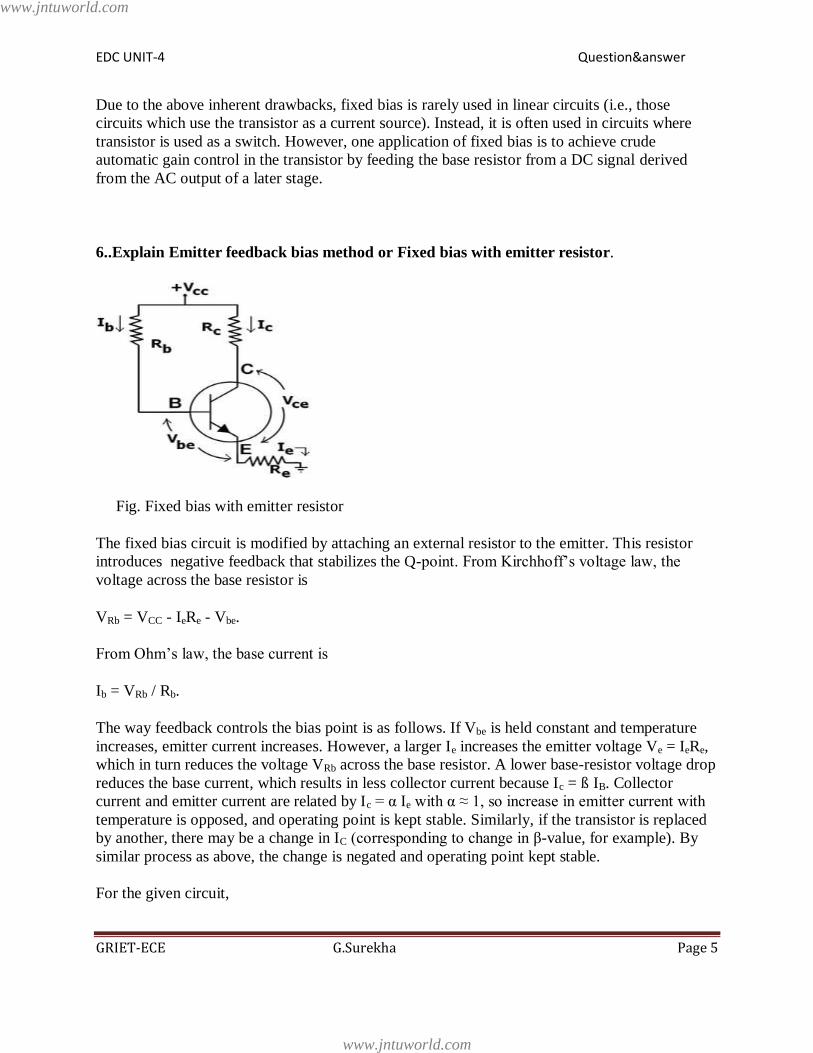
6..Explain Emitter feedback bias method or Fixed bias with emitter resistor.
Fig. Fixed bias with emitter resistor
The fixed bias circuit is modified by attaching an external resistor to the emitter. This resistor
introduces negative feedback that stabilizes the Q-point. From Kirchhoff’s voltage law, the
voltage across the base resistor is
VRb = VCC - IeRe - Vbe.
From Ohm’s law, the base current is
Ib = VRb / Rb.
The way feedback controls the bias point is as follows. If Vbe is held constant and temperature
increases, emitter current increases. However, a larger Ie increases the emitter voltage Ve = IeRe,
which in turn reduces the voltage VRb across the base resistor. A lower base-resistor voltage drop
reduces the base current, which results in less collector current because Ic = ß IB. Collector
current and emitter current are related by Ic = α Ie with α ≈ 1, so increase in emitter current with
temperature is opposed, and operating point is kept stable. Similarly, if the transistor is replaced
by another, there may be a change in IC (corresponding to change in β-value, for example). By
similar process as above, the change is negated and operating point kept stable.
For the given circuit,
www.jntuworld.com
www.jntuworld.com
EDC UNIT-4 Question&answer
GRIET-ECE G.Surekha Page 6
IB = (VCC - Vbe)/(RB + (β+1)RE).
Stability Factor S = 1
1dIB
dIC
Hence stability factor for this method is
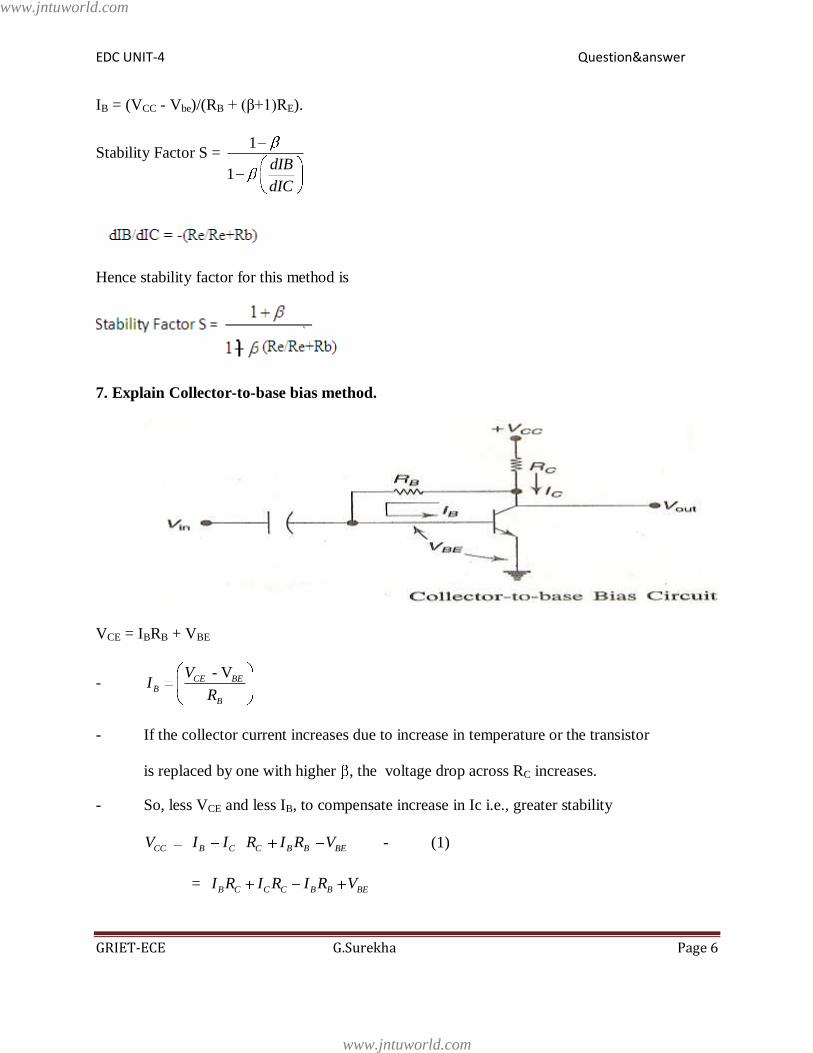
7. Explain Collector-to-base bias method.
VCE = IBRB + VBE
- - VCE BE
B
B
VI
R
- If the collector current increases due to increase in temperature or the transistor
is replaced by one with higher , the voltage drop across RC increases.
- So, less VCE and less IB, to compensate increase in Ic i.e., greater stability
CC B C C B B BEV I I R I R V - (1)
= B C C C B B BEI R I R I R V
www.jntuworld.com
www.jntuworld.com

EDC UNIT-4 Question&answer
GRIET-ECE G.Surekha Page 7
= B C B C C BEI R R I R V
Or CC BE C CB
V V I RI
RC RB - (2)
CIB
IC C B
Rd
d R R - (3)
Stability Factor:
1
1 B
C
SdI
dI
Putting the value of dIB / dIC from equation (3)
1 1
1 1C C
C B C B
SR R
R R R R
Note: 1) Value of S is less than that of fixed bias (which is S = 1+ )
2. S can be made small and stability improved by making RB small or RC large.
If Rc is small S = 1 + , i.e., stability is poor.
Merits:
Circuit stabilizes the operating point against variations in temperature and β (i.e.
replacement of transistor)
Demerits:
In this circuit, to keep Ic independent of β, the following condition must be met:
which is the case when
www.jntuworld.com
www.jntuworld.com

EDC UNIT-4 Question&answer
GRIET-ECE G.Surekha Page 8
As β-value is fixed (and generally unknown) for a given transistor, this relation can be
satisfied either by keeping Rc fairly large or making Rb very low.
If Rc is large, a high Vcc is necessary, which increases cost as well as precautions
necessary while handling.
If Rb is low, the reverse bias of the collector–base region is small, which limits the
range of collector voltage swing that leaves the transistor in active mode.
The resistor Rb causes an AC feedback, reducing the Voltage gain of the amplifier. This
undesirable effect is a trade-off for greater Q-point stability.
Usage: The feedback also decreases the input impedance of the amplifier as seen from the base,
which can be advantageous. Due to the gain reduction from feedback, this biasing form is used
only when the trade-off for stability is warranted.
8. Explain Collector-Emitter Feedback bias method.
VCE = IBRB + VBE
- - VCE BE
B
B
VI
R
- If the collector current increases due to increase in temperature or the transistor
www.jntuworld.com
www.jntuworld.com
EDC UNIT-4 Question&answer
GRIET-ECE G.Surekha Page 9
is replaced by one with higher , the voltage drop across RC increases.
- So, less VCE and less IB, to compensate increase in Ic i.e., greater stability
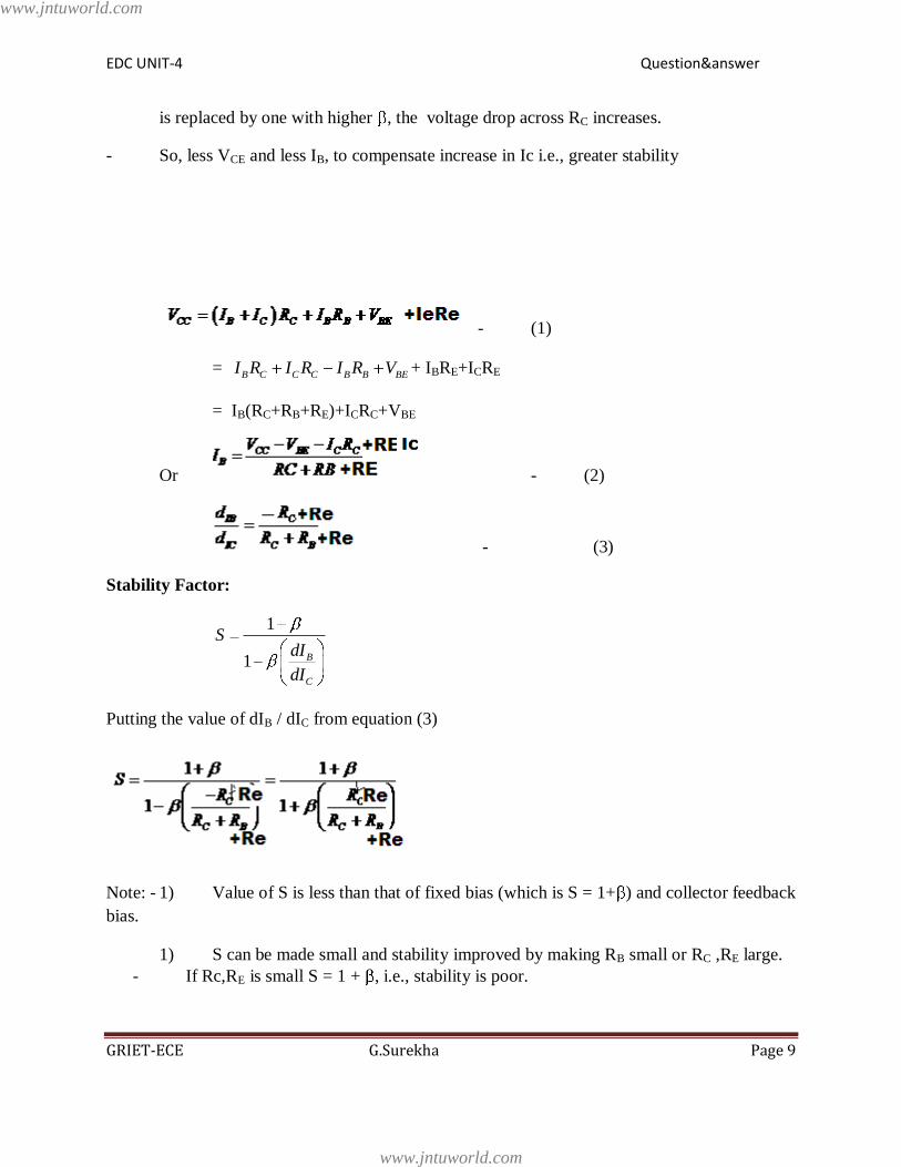
- (1)
= B C C C B B BEI R I R I R V + IBRE+ICRE
= IB(RC+RB+RE)+ICRC+VBE
Or - (2)
- (3)
Stability Factor:
1
1 B
C
SdI
dI
Putting the value of dIB / dIC from equation (3)
Note: - 1) Value of S is less than that of fixed bias (which is S = 1+ ) and collector feedback
bias.
1) S can be made small and stability improved by making RB small or RC ,RE large.
- If Rc,RE is small S = 1 + , i.e., stability is poor.
www.jntuworld.com
www.jntuworld.com
EDC UNIT-4 Question&answer
GRIET-ECE G.Surekha Page 10
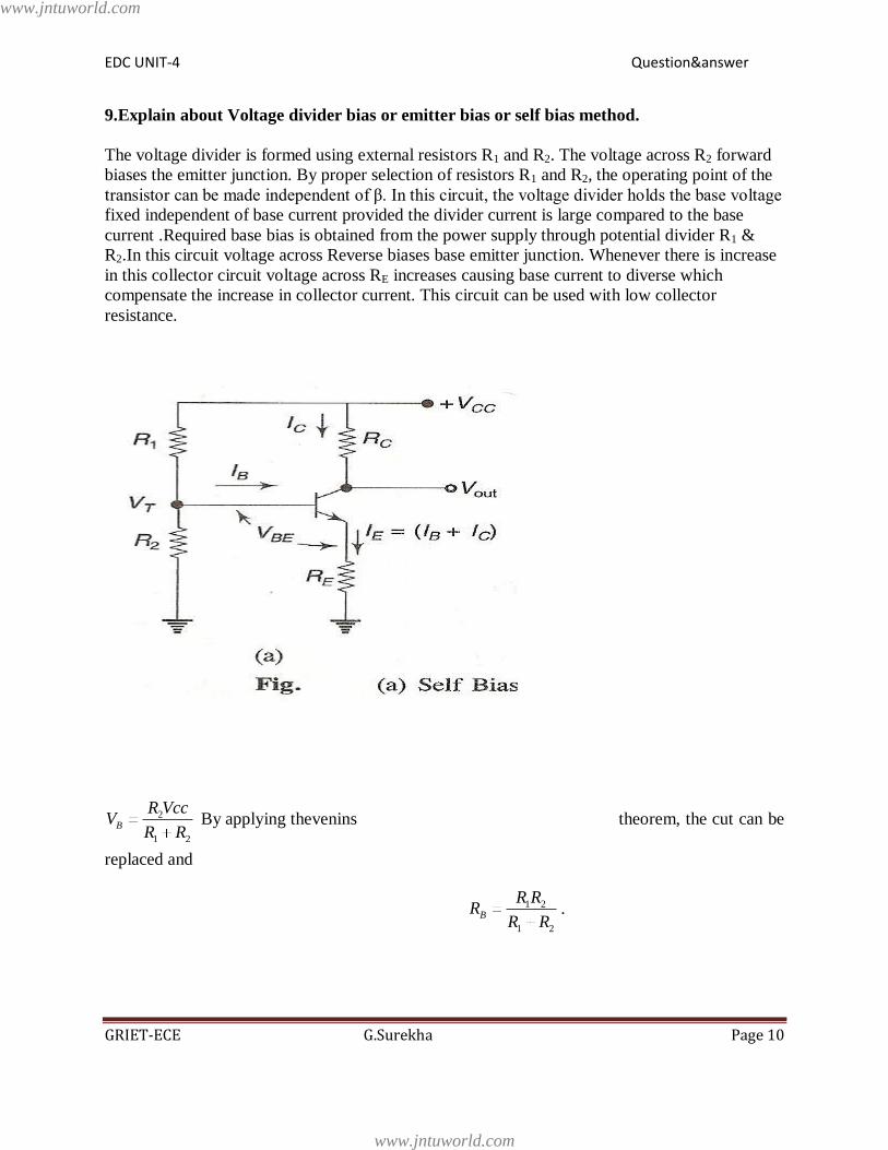
9.Explain about Voltage divider bias or emitter bias or self bias method.
The voltage divider is formed using external resistors R1 and R2. The voltage across R2 forward
biases the emitter junction. By proper selection of resistors R1 and R2, the operating point of the
transistor can be made independent of β. In this circuit, the voltage divider holds the base voltage
fixed independent of base current provided the divider current is large compared to the base
current .Required base bias is obtained from the power supply through potential divider R1 &
R2.In this circuit voltage across Reverse biases base emitter junction. Whenever there is increase
in this collector circuit voltage across RE increases causing base current to diverse which
compensate the increase in collector current. This circuit can be used with low collector
resistance.
2
1 2
B
R VccV
R R By applying thevenins theorem, the cut can be
replaced and
1 2
1 2
B
R RR
R R.
www.jntuworld.com
www.jntuworld.com

EDC UNIT-4 Question&answer
GRIET-ECE G.Surekha Page 11
.
Equivalent Circuit: writing loop equation for the basic loop shown
= IBRB + VBE + RE(IB+IC)
= IBRB + VBE + IBRE + ICRE
= IB(RB+RE) + VBE + ICRE
Or IB(RB+RE) = VB – VBE - ICRE
ICRE
Differencing wrt. Ic,
C EB B BE
B E
C C C C
dI RdI dV dVR R
dI dI dI dI
Or ( ) 0 0B
B E E
c
dIR R R
dI
Or B E
c B E
dI R
dI R R - (1)
Stability Factor
1
1 B
c
SdI
dI
www.jntuworld.com
www.jntuworld.com

EDC UNIT-4 Question&answer
GRIET-ECE G.Surekha Page 12
Putting the value of dIB / dIC from equation (1)
1 1 1
1 1B E EE E
B EB E B E
SR R RR R
R RR R R R
Dividing N & D by RE
1 1
(1 ) (2)
1
B E B
E E
B E E B
E E
R R R
R RS
R R R R
R R
If 1 0 1
0, (1 ) 11 0 1
B
E
RS
R (3)
If 1
, 1 11
B
E
RS
R
So, (a) for smaller value of RB stability is better, but large power will be wasted in R1
& R2. S is independent of β.
(b)For fixed RB/RE, S increases with (see eqn. 2) i.e., stability decreases with
increase in .
Merits:
Unlike above circuits, only one dc supply is necessary.
Operating point is almost independent of β variation.
Operating point stabilized against shift in temperature.
Demerits:
As β-value is fixed for a given transistor, this relation can be satisfied either by keeping
RE fairly large, or making R1||R2 very low.
If RE is of large value, high VCC is necessary. This increases cost as well as
precautions necessary while handling.
www.jntuworld.com
www.jntuworld.com
EDC UNIT-4 Question&answer
GRIET-ECE G.Surekha Page 13
If R1 || R2 is low, either R1 is low, or R2 is low, or both are low. A low R1 raises
VB closer to VC, reducing the available swing in collector voltage, and limiting
how large RC can be made without driving the transistor out of active mode. A
low R2 lowers Vbe, reducing the allowed collector current. Lowering both resistor
values draws more current from the power supply and lowers the input resistance
of the amplifier as seen from the base.
AC as well as DC feedback is caused by RE, which reduces the AC voltage gain of the
amplifier. A method to avoid AC feedback while retaining DC feedback is discussed
below.
Usage:
The circuit's stability and merits as above make it widely used for linear circuits.
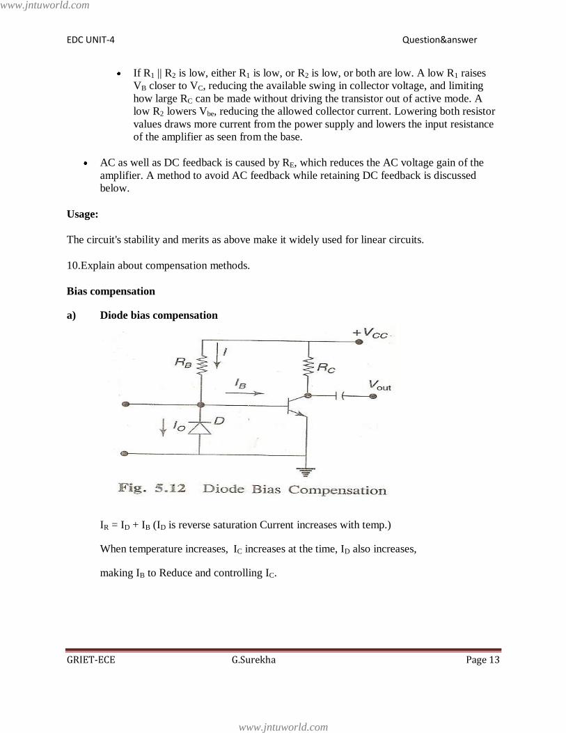
10.Explain about compensation methods.
Bias compensation
a) Diode bias compensation
IR = ID + IB (ID is reverse saturation Current increases with temp.)
When temperature increases, IC increases at the time, ID also increases,
making IB to Reduce and controlling IC.
www.jntuworld.com
www.jntuworld.com

EDC UNIT-4 Question&answer
GRIET-ECE G.Surekha Page 14
b) Thermistor Bias compensation: -
- RT is having negative temp. Coefficient
i.e., temperature RT .RT
- When temperature increases RT decreases
thereby reducing base bias voltage &
base current and hence collect to current.
c) Sensistor Bias compensation.
- Rs is sensistor (resistance) having
positive temperature coefficient.
- When temp. Rs. VR2
Base bias voltage Base current . Collector current controlled.
Problems
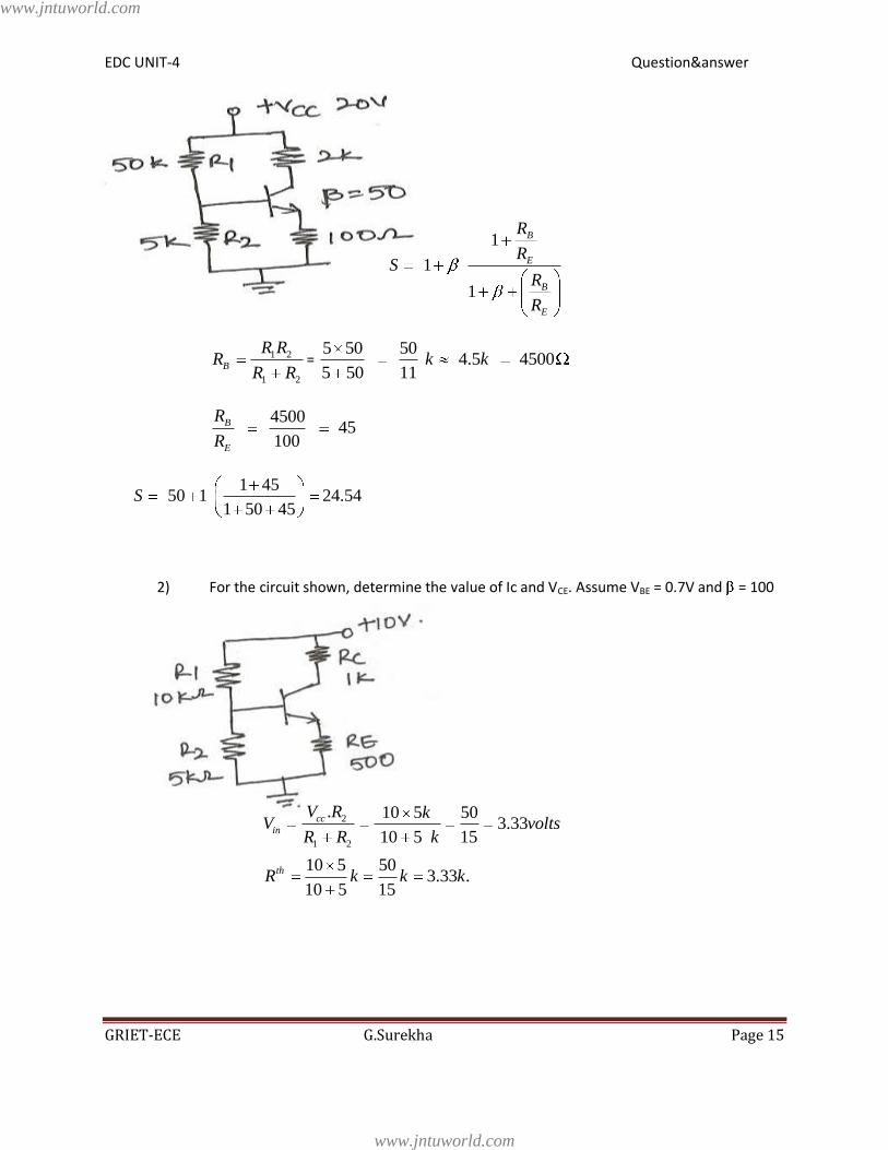
1. Find out stability factor of the circuit given below:
Stability factor of self-biased Circuit given by:
www.jntuworld.com
www.jntuworld.com
EDC UNIT-4 Question&answer
GRIET-ECE G.Surekha Page 15
1
1
1
B
E
B
E
R
RS
R
R
1 2
1 2
B
R RR
R R=
5 50 50 4.5 4500
5 50 11k k
4500
45100
B
E
R
R
1 4550 1 24.54
1 50 45S
2) For the circuit shown, determine the value of Ic and VCE. Assume VBE = 0.7V and = 100
2
1 2
. 10 5 503.33
10 5 15
10 5 503.33 .
10 5 15
cc
in
th
V R kV volts
R R k
R k k k
www.jntuworld.com
www.jntuworld.com
EDC UNIT-4 Question&answer
GRIET-ECE G.Surekha Page 16
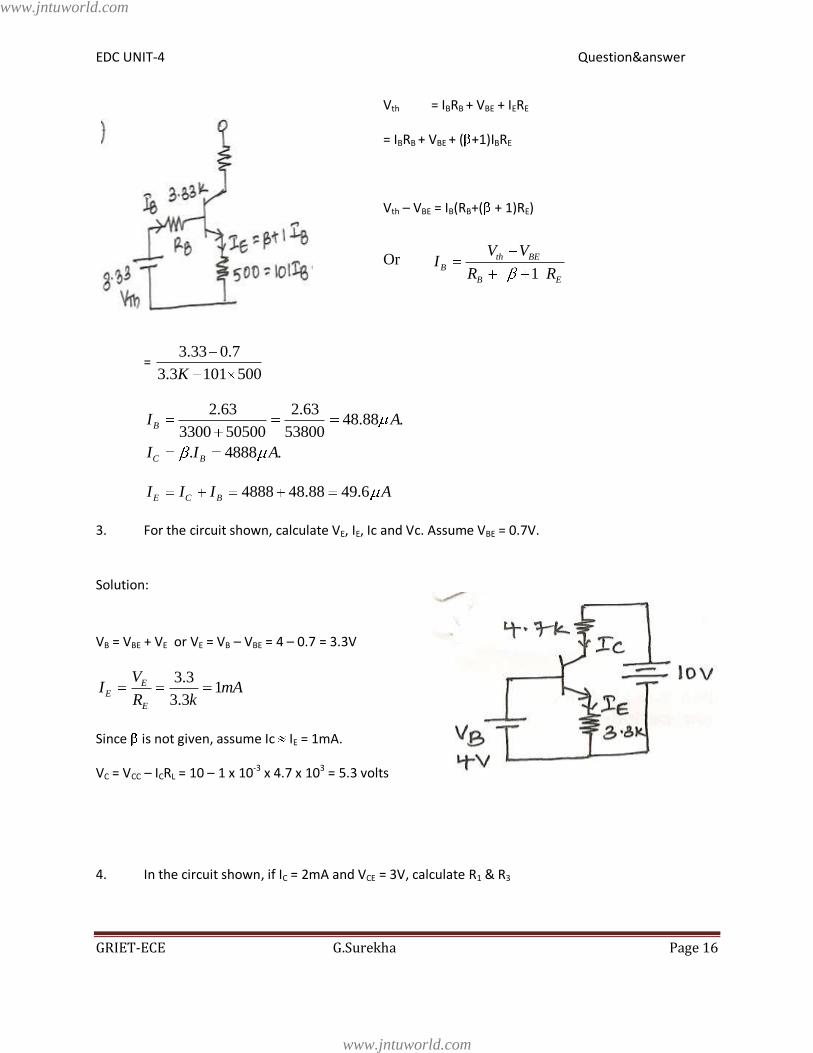
Vth = IBRB + VBE + IERE
= IBRB + VBE + ( +1)IBRE
Vth – VBE = IB(RB+( + 1)RE)
Or 1
th BE
B
B E
V VI
R R
= 3.33 0.7
3.3 101 500K
2.63 2.6348.88 .
3300 50500 53800
. 4888 .
B
C B
I A
I I A
4888 48.88 49.6E C BI I I A
3. For the circuit shown, calculate VE, IE, Ic and Vc. Assume VBE = 0.7V.
Solution:
VB = VBE + VE or VE = VB – VBE = 4 – 0.7 = 3.3V
3.31
3.3
E
E
E
VI mA
R k
Since is not given, assume Ic IE = 1mA.
VC = VCC – ICRL = 10 – 1 x 10-3 x 4.7 x 103 = 5.3 volts
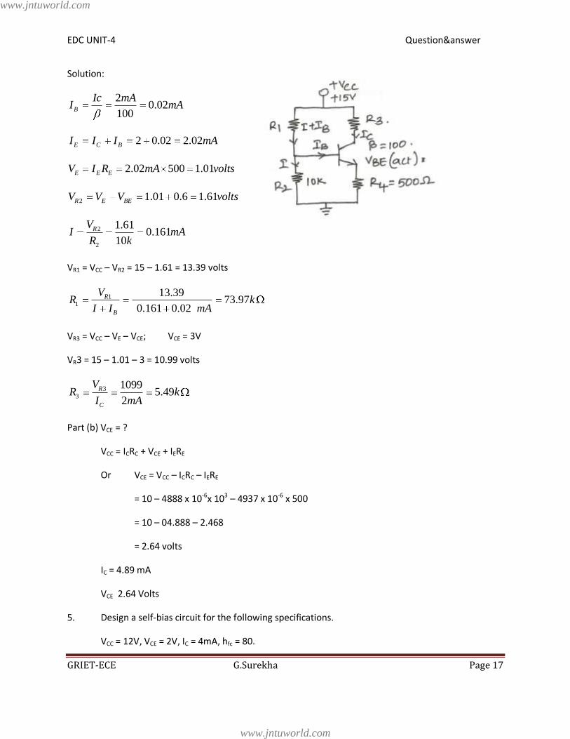
4. In the circuit shown, if IC = 2mA and VCE = 3V, calculate R1 & R3
www.jntuworld.com
www.jntuworld.com
EDC UNIT-4 Question&answer
GRIET-ECE G.Surekha Page 17
Solution:
20.02
100B
Ic mAI mA
2 0.02 2.02E C BI I I mA
2.02 500 1.01E E EV I R mA volts
2 1.01 0.6 1.61R E BEV V V volts
2
2
1.610.161
10
RVI mA
R k
VR1 = VCC – VR2 = 15 – 1.61 = 13.39 volts
1
1
13.3973.97
0.161 0.02
R
B
VR k
I I mA
VR3 = VCC – VE – VCE; VCE = 3V
VR3 = 15 – 1.01 – 3 = 10.99 volts
3
3
10995.49
2
R
C
VR k
I mA
Part (b) VCE = ?
VCC = ICRC + VCE + IERE
Or VCE = VCC – ICRC – IERE
= 10 – 4888 x 10-6x 10³ – 4937 x 10-6 x 500
= 10 – 04.888 – 2.468
= 2.64 volts
IC = 4.89 mA
VCE 2.64 Volts
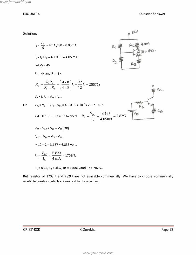
5. Design a self-bias circuit for the following specifications.
VCC = 12V, VCE = 2V, IC = 4mA, hfc = 80.
www.jntuworld.com
www.jntuworld.com
EDC UNIT-4 Question&answer
GRIET-ECE G.Surekha Page 18
Solution:
IB = CI = 4mA / 80 = 0.05mA
IE = IC + IB = 4 + 0.05 = 4.05 mA
Let VB = 4V.
R2 = 4k and R1 = 8K
1 2
1 2
4 8 322667
4 8 12B
R RR k k
R R
VB = IBRB + VBE + VRE
Or VRE = VB – IBRB – VBE = 4 – 0.05 x 10-3 x 2667 – 0.7
= 4 – 0.133 – 0.7 = 3.167 volts 3.167
7.824.05
RE
E
E
VR
I mA
VCC = VRC + VCE + VRE (OR)
VRC = VCC – VCE - VRE
= 12 – 2 – 3.167 = 6.833 volts
Rc = RC
C
V
I =
6.833
4 mA = 1708 .
R1 = 8k , R2 = 4k , Rc = 1708 and Rc = 782 .
But resistor of 1708 and 782 are not available commercially. We have to choose commercially
available resistors, which are nearest to these values.
www.jntuworld.com
www.jntuworld.com
Related Documents