1 EX/P5-14 ECH Power Deposition at 3 rd Harmonic in high Elongation TCV Discharges Sustained by 2 nd Harmonic Current Profile Broadening A. Pochelon 1 , G. Arnoux 1 , Y. Camenen 1 , A. Scarabosio 1 , S. Alberti 1 , F. Hofmann 1 , A. Manini 1 , R. Behn 1 , P. Bosshard 1 , P. Blanchard 1 , S. Coda 1 , T.P. Goodman 1 , M.A. Henderson 1 , J.-Ph. Hogge 1 , A. Karpushov 1 , J.-M. Moret 1 , E. Nelson-Melby 1 , L. Porte 1 , O. Sauter 1 , A. Sushkov 2 , M.Q. Tran 1 . 1) Centre de Recherches en Physique des Plasmas, Association EURATOM-Confédération Suisse, Ecole Polytechnique Fédérale de Lausanne EPFL, 1015 Lausanne, Switzerland 2) RRC Kurchatov, Moscow e-mail contact of main author: [email protected] Abstract. This paper summarises the present effort aimed at developing high elongation heated discharges and testing their confinement properties at normalised currents for which the highest ideal MHD β -limits are predicted. 2 nd harmonic (X2) far off-axis ECH/CD is used to stabilise the plasma vertically at high elongation by broadening the current profile in stationary conditions (during the current flat top and over several current diffusion times). Current broadening is maximal for a power deposition in a narrow region (~a/5), for a finite toroidal injection angle and for high plasma density using upper lateral launchers to minimise refraction. In these discharges which are twice X2 overdense in the centre, 3 rd harmonic (X3) is injected from a top launcher to deposit power in the centre and increase the central pressure, simultaneously with far off-axis X2. Using modulated X3, full absorption is measured by the diamagnetic probe. Absorption higher than calculated by thermal ray tracing is occasionally found, indicating absorption on the electron bulk as well as in the suprathermal electron population sometimes with a hollow deposition profile. The high sensitivity of the power coupling to the beam angle stresses the need for developing a mirror feedback scheme [1] to increase the coupling efficiency in transient heating scenarios. 1. Introduction Plasma shaping, and in particular elongation, is a means to improve tokamak performance [2]. Highly elongated discharges tend to be vertically unstable and can only be stabilised by providing sufficient current density close to the plasma edge [3]. For Ohmic discharges, this is achieved by operating at a low safety factor q edge (2.2<κ<2.8, I N =I p /aB~2.8- 3.5MA/mT). However, in order to reach maximum β-values predicted by ideal MHD for highly elongated plasmas, one has to produce discharges at intermediate I N values, of the order of 2MA/mT. For these values Ohmic discharges are vertically unstable, but TCV plasmas can be maintained stable by current profile broadening using far off-axis 2 nd harmonic X-mode ECH/CD (X2) [4-7]. This leads to highly elongated discharges (κ~2.48) at low current and high safety factor (I N ~1.05MA/mT, q edge ~10) using 3/4 of the upper lateral port installed EC power [8]. X3 power has been coupled to the plasma in ohmic condition and in combination with X2 ECW [9-12]. In this paper we are using simultaneously far off-axis 2 nd harmonic ECW for plasma shaping and 3 rd harmonic (X3), with the aim of measuring and optimising the coupling of X3 power deposition. 2. Experimental set-up TCV is equipped with 4.5MW ECH nominal power for 2s pulse length: 3MW at the 2 nd harmonic and 1.5MW at the 3 rd harmonic. The X2 system consists of six 475kW gyrotrons at 82.7GHz with six independent low field side (LFS) launchers, four upper lateral and two equatorial, steerable during the discharge. The X3 system consists of three 420kW gyrotrons at 118GHz using a single top launcher, also steerable during the discharge. The cut-off densities of X2 and X3 waves are 4.25 and 11.5 10 19 m -3 respectively. Using power modulation techniques, the total absorbed power is measured by a diamagnetic loop (DML) [13,14], and the local deposition is measured with a 64 channels soft X-ray wire chamber (MPX) filled with Xenon, sensitive between 2-25keV (10% efficiency limits) [14,15]. The level of the suprathermal electron population is obtained by comparing HFS ECE radiation temperatures, T e ECE , with the Thomson temperatures T e [10].

Welcome message from author
This document is posted to help you gain knowledge. Please leave a comment to let me know what you think about it! Share it to your friends and learn new things together.
Transcript

1 EX/P5-14
ECH Power Deposition at 3rd Harmonic in high Elongation TCV DischargesSustained by 2nd Harmonic Current Profile Broadening
A. Pochelon1, G. Arnoux1, Y. Camenen1, A. Scarabosio1, S. Alberti1, F. Hofmann1,A. Manini1, R. Behn1, P. Bosshard1, P. Blanchard1, S. Coda1, T.P. Goodman1,M.A. Henderson1, J.-Ph. Hogge1, A. Karpushov1, J.-M. Moret1, E. Nelson-Melby1, L. Porte1,O. Sauter1, A. Sushkov2, M.Q. Tran1.
1) Centre de Recherches en Physique des Plasmas, Association EURATOM-Confédération Suisse,Ecole Polytechnique Fédérale de Lausanne EPFL, 1015 Lausanne, Switzerland2) RRC Kurchatov, Moscow
e-mail contact of main author: [email protected]
Abstract. This paper summarises the present effort aimed at developing high elongation heated discharges andtesting their confinement properties at normalised currents for which the highest ideal MHD β-limits arepredicted. 2nd harmonic (X2) far off-axis ECH/CD is used to stabilise the plasma vertically at high elongation bybroadening the current profile in stationary conditions (during the current flat top and over several currentdiffusion times). Current broadening is maximal for a power deposition in a narrow region (~a/5), for a finitetoroidal injection angle and for high plasma density using upper lateral launchers to minimise refraction. In thesedischarges which are twice X2 overdense in the centre, 3rd harmonic (X3) is injected from a top launcher todeposit power in the centre and increase the central pressure, simultaneously with far off-axis X2. Usingmodulated X3, full absorption is measured by the diamagnetic probe. Absorption higher than calculated bythermal ray tracing is occasionally found, indicating absorption on the electron bulk as well as in thesuprathermal electron population sometimes with a hollow deposition profile. The high sensitivity of the powercoupling to the beam angle stresses the need for developing a mirror feedback scheme [1] to increase thecoupling efficiency in transient heating scenarios.
1. Introduction
Plasma shaping, and in particular elongation, is a means to improve tokamakperformance [2]. Highly elongated discharges tend to be vertically unstable and can only bestabilised by providing sufficient current density close to the plasma edge [3]. For Ohmicdischarges, this is achieved by operating at a low safety factor qedge (2.2<κ<2.8, IN=Ip/aB~2.8-3.5MA/mT). However, in order to reach maximum β-values predicted by ideal MHD forhighly elongated plasmas, one has to produce discharges at intermediate IN values, of theorder of 2MA/mT. For these values Ohmic discharges are vertically unstable, but TCVplasmas can be maintained stable by current profile broadening using far off-axis 2nd
harmonic X-mode ECH/CD (X2) [4-7]. This leads to highly elongated discharges (κ~2.48) atlow current and high safety factor (IN~1.05MA/mT, qedge~10) using 3/4 of the upper lateralport installed EC power [8]. X3 power has been coupled to the plasma in ohmic condition andin combination with X2 ECW [9-12]. In this paper we are using simultaneously far off-axis2nd harmonic ECW for plasma shaping and 3rd harmonic (X3), with the aim of measuring andoptimising the coupling of X3 power deposition.
2. Experimental set-up
TCV is equipped with 4.5MW ECH nominal power for 2s pulse length: 3MW at the2nd harmonic and 1.5MW at the 3rd harmonic. The X2 system consists of six 475kW gyrotronsat 82.7GHz with six independent low field side (LFS) launchers, four upper lateral and twoequatorial, steerable during the discharge. The X3 system consists of three 420kW gyrotronsat 118GHz using a single top launcher, also steerable during the discharge. The cut-offdensities of X2 and X3 waves are 4.25 and 11.5 1019m-3 respectively.
Using power modulation techniques, the total absorbed power is measured by adiamagnetic loop (DML) [13,14], and the local deposition is measured with a 64 channels softX-ray wire chamber (MPX) filled with Xenon, sensitive between 2-25keV (10% efficiencylimits) [14,15]. The level of the suprathermal electron population is obtained by comparingHFS ECE radiation temperatures, Te ECE, with the Thomson temperatures Te [10].
2 EX/P5-14
3. High elongation stabilised by far off-axis ECH/CD X2
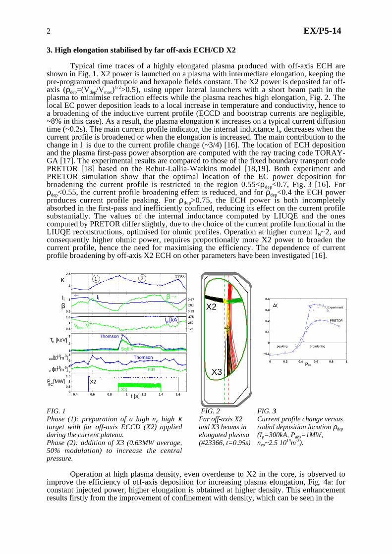
Typical time traces of a highly elongated plasma produced with off-axis ECH areshown in Fig. 1. X2 power is launched on a plasma with intermediate elongation, keeping thepre-programmed quadrupole and hexapole fields constant. The X2 power is deposited far off-axis (ρdep=(Vdep/Vmax)
1/2>0.5), using upper lateral launchers with a short beam path in theplasma to minimise refraction effects while the plasma reaches high elongation, Fig. 2. Thelocal EC power deposition leads to a local increase in temperature and conductivity, hence toa broadening of the inductive current profile (ECCD and bootstrap currents are negligible,~8% in this case). As a result, the plasma elongation κ increases on a typical current diffusiontime (~0.2s). The main current profile indicator, the internal inductance li, decreases when thecurrent profile is broadened or when the elongation is increased. The main contribution to thechange in li is due to the current profile change (~3/4) [16]. The location of ECH depositionand the plasma first-pass power absorption are computed with the ray tracing code TORAY-GA [17]. The experimental results are compared to those of the fixed boundary transport codePRETOR [18] based on the Rebut-Lallia-Watkins model [18,19]. Both experiment andPRETOR simulation show that the optimal location of the EC power deposition forbroadening the current profile is restricted to the region 0.55<ρdep<0.7, Fig. 3 [16]. Forρdep<0.55, the current profile broadening effect is reduced, and for ρdep<0.4 the ECH powerproduces current profile peaking. For ρdep>0.75, the ECH power is both incompletelyabsorbed in the first-pass and inefficiently confined, reducing its effect on the current profilesubstantially. The values of the internal inductance computed by LIUQE and the onescomputed by PRETOR differ slightly, due to the choice of the current profile functional in theLIUQE reconstructions, optimised for ohmic profiles. Operation at higher current IN~2, andconsequently higher ohmic power, requires proportionally more X2 power to broaden thecurrent profile, hence the need for maximising the efficiency. The dependence of currentprofile broadening by off-axis X2 ECH on other parameters have been investigated [16].
2
2.5
0.5
1
0.5
1
1.5
1
2
3
0.4 0.6 0.8 1 1.2 1.4 1.62
4
6
8
0.4 0.6 0.8 1 1.2 1.4 1.60
0.5
1
1.5
t [s]
I [kA]p
li
κ
V [V]loop
P [MW]EC
e l 019m-3]
T [keV]e
eo[ 019m-3]1
[1
β
X2
X3
Thomson
Soft X
125
250
375
0.33
0.67
Thomson
FIR
βli
23366
[%]
---><---
1 2
X2
X30 0.2 0.4 0.6 0.8 1
−0.1
0
0.1
0.2
0.3
0.4
Experiment
PRETOR
ρdep
∆l i*
peaking broadening
FIG. 1Phase (1): preparation of a high ne high κtarget with far off-axis ECCD (X2) appliedduring the current plateau.Phase (2): addition of X3 (0.63MW average,50% modulation) to increase the centralpressure.
FIG. 2Far off-axis X2and X3 beams inelongated plasma(#23366, t=0.95s)
FIG. 3Current profile change versusradial deposition location ρdep
(Ip=300kA, Pabs=1MW,neo~2.5 1019m-3).
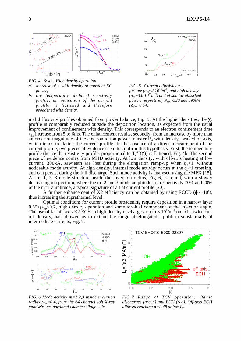
Operation at high plasma density, even overdense to X2 in the core, is observed toimprove the efficiency of off-axis deposition for increasing plasma elongation, Fig. 4a: forconstant injected power, higher elongation is obtained at higher density. This enhancementresults firstly from the improvement of confinement with density, which can be seen in the
3 EX/P5-14
2.2 2.4 2.6 2.8 3 3.2
1.9
2
2.1
2.2
2.3
2.4
κ2 gyrotrons
3 gyrotro
ns
n l [1019m-3]e
390kA
0 0.2 0.4 0.6 0.8 10
0.5
1
1.5
2
2.5
3
3.5
4
x 104
ρvol
T
[eV
]
e3/2
3/2
n =2.2eo19
n =2eo19
n =3.4eo19
#22304#22509#22510
300kA
0.4 0.5 0.6 0.7 0.8 0.9 10
5
10
15
20
25
300kA
22306, 22515. t=1.4s
ρvol
χ[m /s]2
e
520<P <590kWabs
n =eo19
3.7
2
n =eo19
FIG. 4a & 4b High density operation:a) increase of κ with density at constant EC
power,b) the temperature deduced resistivity
profile, an indication of the currentprofile, is flattened and thereforebroadened with density.
FIG. 5 Current diffusivity χe
for low (neo~2 1019m-3) and high density(neo~3.6 1019m-3) and at similar absorbedpower, respectively Pabs~520 and 590kW(ρdep~0.54).
mal diffusivity profiles obtained from power balance, Fig. 5. At the higher densities, the χeprofile is comparably reduced outside the deposition location, as expected from the usualimprovement of confinement with density. This corresponds to an electron confinement timeτEe increase from 5 to 6ms. The enhancement results, secondly, from an increase by more thanan order of magnitude of the electron to ion power transfer Pei with density, peaked on axis,which tends to flatten the current profile. In the absence of a direct measurement of thecurrent profile, two pieces of evidence seem to confirm this hypothesis. First, the temperatureprofile (hence the resistivity profile, proportional to Te
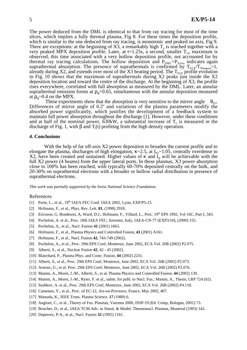
3/2(ρ)) is flattened, Fig. 4b. The secondpiece of evidence comes from MHD activity. At low density, with off-axis heating at lowcurrent, 300kA, sawteeth are lost during the elongation ramp-up when qo>1, withoutnoticeable mode activity. At high density, internal mode activity occurs at the qo~1 crossing,and can persist during the full discharge. Such mode activity is analysed using the MPX [15].An m=1, 2, 3 mode structure inside the inversion radius, Fig. 6, is found, with a slowlydecreasing m-spectrum, where the m=2 and 3 mode amplitude are respectively 70% and 20%of the m=1 amplitude, a typical signature of a flat current profile [20].
A further enhancement of X2 efficiency can be obtained by using ECCD (ϕ~±10o),thus increasing the suprathermal level.
Optimal conditions for current profile broadening require deposition in a narrow layer0.55<ρdep<0.7, high density operation and some toroidal component of the injection angle.The use of far off-axis X2 ECH in high-density discharges, up to 8 1019m-3 on axis, twice cut-off density, has allowed us to extend the range of elongated equilibria substantially atintermediate currents, Fig. 7.
−0.8 −0.6 −0.4 −0.2 0 0.2 0.4 0.6 0.80
0.02
0.04
0.06
0.08
0.1
0.12
−0.8 −0.6 −0.4 −0.2 0 0.2 0.4 0.6 0.8−4
−2
0
2
4
ampl
itide
PS
D [a
.u.]
phas
e [r
ad]
ρvol
ρvol
m=3
m=2
m=1
m=1
m=3
m=2
#22621480kA
A x 5m=3
0.7s
κ
I =
I/aB
[MA
/mT
]N
TCV SHOTS 5000-22897
OH
ECHoff-axis
FIG. 6 Mode activity m=1,2,3 inside inversionradius ρinv=0.4, from the 64 channel soft X-raymultiwire proportional chamber diagnostic.
FIG. 7 Range of TCV operation: Ohmicdischarges (green) and ECH (red). Off-axis ECHallowed reaching κ=2.48 at low IN.

4 EX/P5-14
4. X3 power deposition in high elongation discharges
High-elongation high-density discharges, overdense to X2 in the core, are developedultimately for β-limit and confinement studies. They provide the target plasmas for X3heating and deposition studies. The discharges have high neTe to maximise X3 absorption andhigh κ to enhance the absorption by the geometrical effect of shallow incidence on theresonance.
In discharge 23366, see Fig. 1 (390kA, ϕX2=+10o, neo~6->7 1019m-3, Pabs_X2= 1.41MWdeposited at ρdep= 0.7 to 0.5), we apply 0.63MW average X3 power with half of the powermodulated at 337Hz. The elongation reached with X2, κmax~2.43, is limited by verticalstability. Later, during the X3 phase, the central deposition peaks the current profile. Theresulting increase of li and decrease of κ can only be partly compensated by the shaping coils:keeping the elongation constant, while X3 peaks the current profile, leads to an increase of thevertical instability growth rate, limiting the maximal stable elongation.
The optimal poloidal mirror angle θX3 is found by maximising the soft X-raytemperature in a mirror angle sweep. The optimal X3 power modulation frequency (337Hz),yielding reliable results for both the DML and MPX, gives a phase of the response close to90o.
0 0.1 0.2 0.3 0.4 0.5 0.6 0.7 0.8 0.9 10
1
2
3
4
5
6
P EC
(W/m
3 W)
TORAY Power density W/m3 W
t=0.95s, P = 62%
t=0.95s, P = 98%
t=1.25s, P = 59%
t=1.25s, P = 97%
ρvol
23366
X2
X3
1.25s
1.25s
0.95s
0.95s
abs X3
abs X2
abs X3
abs X2
FIG. 9 X2 and X3 beamsa) at start of X3 (neo= 5.8 1019m-3) andb) at t=1.25s (neo=6.4 1019m-3)
0.9 1 1.1 1.2 1.30
200
400
Pow
er [k
W]
MECH (335 Hz) time window for shot 23366
P TORAYP DML
0.9 1 1.1 1.2 1.3
−0.5
0
0.5
Time [s]
ρ(ψ
)
deposition profile0.9 1 1.1 1.2 1.31
2
3
4
Te
[keV
]
Temax
thomson
Te−X
0.2 0.3 0.4 0.5 0.6 0.7
0.5
1
1.5
2
2.5
ρvol
e E
CE
e T
hom
TT
[keV
]
0.5s OH
0.95s X3/X2
1.3s X3/X2
0.9s X2
23366
FIG. 8a) X3 absorbed power from DML and from
ray tracing.b) Electron temperature from Thomson and
soft X-ray,c) Power deposition profile on the MPX,
showing different power deposition profilewidth, from peaked to hollow.
FIG. 10 Te ECE (plain) > Te Thomson (dashed) profilesindicating suprathermal emission during X2/X3:1) t=0.5s, ohmic Te Thom,2) t=0.9s, X2: Te ECE max. just inside ρdep=0.59,
schem. indicated, peaking toward axis,remark Te Thom(ρ) broadened by X2,
3) t=0.95s, X3/X2: Te ECE ~ Te Thom in centre,bigger at ρdep>0.5; strong X3 bulk heatingt=1.3s, X3/X2: Te ECE > Te Thom at ρdep>0.6,centre unknown.
5 EX/P5-14
The power deduced from the DML is identical to that from ray tracing for most of the timeslices, which implies a fully thermal plasma, Fig 8. For these times the deposition profile,which is similar to the one deduced from ray tracing, is monotonic and peaked on axis, Fig 9.There are exceptions: at the beginning of X3, a remarkably high Te is reached together with avery peaked MPX deposition profile. Later, at t=1.25s, a second, smaller TeX maximum isobserved, this time associated with a very hollow deposition profile, not accounted for bythermal ray tracing calculations. The hollow deposition and PDML>PToray indicates againsuprathermal absorption. The presence of suprathermals is confirmed by TECE/TThomson>1,already during X2, and extends over most of the X3 heating period. The TECE profile evolutionin Fig. 10 shows that the maximum of suprathermals during X2 peaks just inside the X2deposition location and toward the centre of the discharge. At the beginning of X3, the profilerises everywhere, correlated with full absorption as measured by the DML. Later, an annularsuprathermal emission forms at ρψ=0.65, simultaneous with the annular deposition measuredat ρψ~0.4 on the MPX.
These experiments show that the absorption is very sensitive to the mirror angle θX3.Differences of mirror angle of 0.2o and variations of the plasma parameters modify theabsorbed power significantly, which justifies the development of a feedback system tomaintain full power absorption throughout the discharge [1]. However, under these conditionsand at half of the nominal power, 630kW, a substantial increase of Te is measured in thedischarge of Fig. 1, with β and Ti(t) profiting from the high density operation.
4. Conclusions
With the help of far off-axis X2 power deposition to broaden the current profile and toelongate the plasma, discharges of high elongation, κ~2.5, at IN,~1.05, centrally overdense toX2, have been created and sustained. Higher values of κ and IN will be achievable with thefull X2 power (4 beams) from the upper lateral ports. In these plasmas, X3 power absorptionclose to 100% has been reached, with typically 60-70% deposited centrally on the bulk, and20-30% on suprathermal electrons with a broader or hollow radial distribution in presence ofsuprathermal electrons.
This work was partially supported by the Swiss National Science Foundation.
References[1] Porte, L., et al., 19th IAEA FEC Conf. IAEA 2002, Lyon, EXP/P5-15.
[2] Hofmann, F., et al., Phys. Rev. Lett. 81, (1998) 2918.
[3] Ericsson, G, Bondeson, A, Ward, D.J., Hofmann, F., Villard, L., Proc. 19th EPS 1992, Vol 16C, Part I, 343.
[4] Pochelon, A. et al., Proc. 18th IAEA FEC, Sorrento, Italy, IAEA-CN-77 (EXP3/10), (2000) 155.
[5] Pochelon, A., et al., Nucl. Fusion 41 (2001) 1663.
[6] Hofmann, F., et al., Plasma Physics and Controlled Fusion, 43 (2001) A161.
[7] Hofmann, F., et al., Nucl. Fusion 42, 743-749 (2002).
[8] Pochelon, A., et al., Proc. 29th EPS Conf, Montreux, June 2002, ECA Vol. 26B (2002) P2.075.
[9] Alberti, S., et al., Nuclear Fusion 42, 42 - 45 (2002).
[10] Blanchard, P., Plasma Phys. and Contr. Fusion, 44 (2002) 2231.
[11] Alberti, S., et al., Proc. 29th EPS Conf, Montreux, June 2002, ECA Vol. 26B (2002) P2.073.
[12] Arnoux, G., et al. Proc. 29th EPS Conf, Montreux, June 2002, ECA Vol. 26B (2002) P2.076.
[13] Manini, A., Moret, J.-M., Alberti, S., et al. Plasma Physics and Controlled Fusion, 44 (2002) 139.
[14] Manini, A., Moret, J.-M., Ryter, F. et al., subm. for publ. to Nucl. Fus.; Manini, A., Thesis, LRP 724 (02).
[15] Sushkov, A. et al., Proc. 29th EPS Conf, Montreux, June 2002, ECA Vol. 26B (2002) P4.118.
[16] Camenen, Y., et al., Proc. of EC-12, Aix-en-Provence, France, May 2002, 407.
[17] Matsuda, K., IEEE Trans. Plasma Science. 17 (1989) 6.
[18] Angioni, C., et al., Theory of Fus. Plasmas, Varenna 2000, ISSP-19 (Ed. Comp, Bologna, 2001) 73.
[19] Boucher, D., et al., IAEA TCM Adv. in Simul. & Model. Thermonucl. Plasmas, Montreal (1993) 142.
[20] Duperrex, P-A., et al., Nucl. Fusion 32 (1992) 1161.
Related Documents