ECEN 468 Advanced Digital System Design Lecture 17: RTL Design 1 Instructor: J. Hu

Welcome message from author
This document is posted to help you gain knowledge. Please leave a comment to let me know what you think about it! Share it to your friends and learn new things together.
Transcript

Digital Design 2e Copyright © 2010 Frank Vahid
ECEN 468 Advanced Digital System Design
Lecture 17: RTL Design
1 Instructor: J. Hu

Digital Design 2e Copyright © 2010 Frank Vahid
2
High-Level State Machines (HLSMs) • Some behaviors too complex for
equations, truth tables, or FSMs • Ex: Soda dispenser
– c: bit input, 1 when coin deposited – a: 8-bit input having value of
deposited coin – s: 8-bit input having cost of a soda – d: bit output, processor sets to 1
when total value of deposited coins equals or exceeds cost of a soda
• FSM can’t represent… – 8-bit input/output – Storage of current total – Addition (e.g., 25 + 10)
a s
c d Soda
dispenser processor
25
1 0 25
1
1
50 0
0
0
0 tot: 25 tot: 50
a
a s
c d Soda
dispenser processor
5.2

Digital Design 2e Copyright © 2010 Frank Vahid
3
HLSMs • High-level state machine
(HLSM) extends FSM with: – Multi-bit input/output – Local storage – Arithmetic operations
Inputs: c (bit), a (8 bits), s (8 bits) Outputs: d (bit) // '1' dispenses soda Local stor a g e : tot (8 bits)
W ait
Disp
Init
d:='0' tot:=0 c’*(tot<s)’ c' * ( tot<s )
d:='1'
c
tot:=tot+a
SodaDispenser
8 8 a s
c d
Soda dispenser processor
• Conventions – Numbers:
• Single-bit: '0' (single quotes) • Integer: 0 (no quotes) • Multi-bit: “0000” (double quotes)
– == for equal, := for assignment – Multi-bit outputs must be
registered via local storage – // precedes a comment
a

Digital Design 2e Copyright © 2010 Frank Vahid
4
Ex: Cycles-High Counter • P = total number (in binary) of cycles that m is 1 • Capture behavior as HLSM
– Preg required (multibit outputs must be registered) • Use to hold count P
m CountHigh clk
32
S_Clr
S_Wt m'
S_Inc m
m m'
Preg := 0
Preg := Preg + 1
// Clear Preg to 0s
// Wait for m == '1'
// Increment Preg
CountHigh Inputs : m (bit) Outputs : P (32 bits) Local storage: Preg
(c)
S_Clr Preg := 0 // Clear Preg to 0s
CountHigh Inputs : m (bit) Outputs : P (32 bits) Local storage: Preg
(a)
?
S_Clr
S_Wt m'
m
Preg := 0 // Clear Preg to 0s
// Wait for m == '1'
CountHigh Inputs : m (bit) Outputs : P (32 bits) Local storage: Preg
(b) ?
a
Note: Could have designed directly using an up-counter. But, that methodology is ad hoc, and won't work for more complex examples, like the next one. a
Preg

Digital Design 2e Copyright © 2010 Frank Vahid
5
Example: Laser-Based Distance Measurer
• Laser-based distance measurement – pulse laser, measure time T to sense reflection – Laser light travels at speed of light, 3*108 m/sec – Distance is thus D = (T sec * 3*108 m/sec) / 2
Object of interest
D
2D = T sec * 3*108 m/sec sensor
laser T (in seconds)
a

Digital Design 2e Copyright © 2010 Frank Vahid
6
Example: Laser-Based Distance Measurer
• Inputs/outputs – B: bit input, from button, to begin measurement – L: bit output, activates laser – S: bit input, senses laser reflection – D: 16-bit output, to display computed distance
sensor
laser T (in seconds)
Laser-based distance measurer 16
from button
to display S
L
D
B to laser
from sensor

Digital Design 2e Copyright © 2010 Frank Vahid
7
Example: Laser-Based Distance Measurer
• Declare inputs, outputs, and local storage – Dreg required for multi-bit output
• Create initial state, name it S0 – Initialize laser to off (L:='0') – Initialize displayed distance to 0 (Dreg:=0)
Laser- based
distance measurer 16
from button
to display S
L
D
B to laser
from sensor a
Inputs : B (bit), S (bit) Outputs : L (bit), D (16 bits) Local storage: Dreg(16)
S0 ?
L := '0' // laser off Dreg := 0 // distance is 0
DistanceMeasurer
(required)
(first state usually initializes the system)
Recall: '0' means single bit, 0 means integer

Digital Design 2e Copyright © 2010 Frank Vahid
8
Example: Laser-Based Distance Measurer
• Add another state, S1, that waits for a button press – B' – stay in S1, keep waiting – B – go to a new state S2
Q: What should S2 do? A: Turn on the laser a
Laser- based
distance measurer 16
from button
to display S
L
D
B to laser
from sensor
S0
L := '0' Dreg := 0
S1 ?
B' // button not pressed
B // button pressed
S0
DistanceMeasurer ...

Digital Design 2e Copyright © 2010 Frank Vahid
9
Example: Laser-Based Distance Measurer
• Add a state S2 that turns on the laser (L:='1') • Then turn off laser (L:='0') in a state S3
Q: What do next? A: Start timer, wait to sense reflection a
Laser- based
distance measurer 16
from button
to display S
L
D
B to laser
from sensor DistanceMeasurer
...
S0 S1 L := '0' Dreg := 0
S2 L := '1'
// laser on
S3 L := '0'
// laser off
B'
B

Digital Design 2e Copyright © 2010 Frank Vahid
10
Example: Laser-Based Distance Measurer
• Stay in S3 until sense reflection (S) • To measure time, count cycles while in S3
– To count, declare local storage Dctr – Initialize Dctr to 0 in S1. In S2 would have been O.K. too.
• Don't forget to initialize local storage—common mistake – Increment Dctr each cycle in S3
Laser-based distance measurer 16
f r om button
t o display S
L
D
B t o laser
f r om sensor
a
S0 S1 S2 S3 L := '0'
Dreg := 0 L := '1' L := '0'
Dctr := Dctr + 1 // count cycles
Dctr := 0 // reset cycle
count
B' S' // no reflection
B S // reflection
?
Inputs : B (bit), S (bit) Outputs : L (bit), D (16 bits) Local storage: Dreg, Dctr (16 bits)
DistanceMeasurer

Digital Design 2e Copyright © 2010 Frank Vahid
11
Example: Laser-Based Distance Measurer
• Once reflection detected (S), go to new state S4 – Calculate distance – Assuming clock frequency is 3x10⁸, Dctr holds number of meters, so
Dreg:=Dctr/2
• After S4, go back to S1 to wait for button again
a
S0 S1 S2 S3 L := '0'
Dreg := 0 L := '1' L := '0'
Dctr := Dctr+1 Dreg := Dctr/2 // calculate D
Dctr := 0
B' S'
B S S4
Inputs : B (bit), S (bit) Outputs : L (bit), D (16 bits) DistanceMeasurer Local storage: Dreg, Dctr (16 bits)
Laser-based
distance measurer 16
from button
to display S
L
D
B t o laser
from sensor

Digital Design 2e Copyright © 2010 Frank Vahid
12
HLSM Actions: Updates Occur Next Clock Cycle • Local storage updated on clock edges only
– Enter state on clock edge – Storage writes in that state occur on next clock edge – Can think of as occurring on outgoing transitions
• Thus, transition conditions use the OLD value, not the newly-written value – Example:
S3 Dctr := Dctr+1
S'
S
S3 Dctr := Dctr+1
S' /
S /
Dctr := Dctr+1
S0 S1 P := '1'
Jreg := Jreg + 1 P := '0'
Jreg := 1
B'
B
Inputs : B (bit) Outputs : P (bit) // if B, 2 cycles high Local storage: Jreg (8 bits)
!(Jreg<2) Jreg<2 ? 1
S0
1 2
S1
2
S1 clk clk
Jreg
B
S0
P
3
( a ) ( b )
3

Digital Design 2e Copyright © 2010 Frank Vahid
13
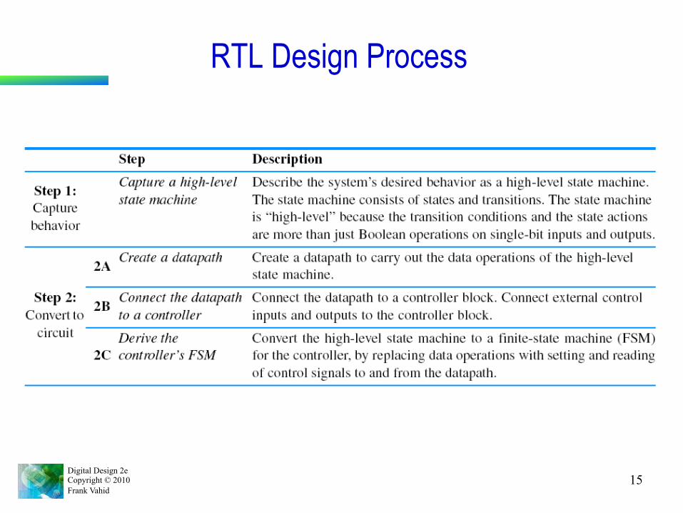
RTL Design Process • Capture behavior • Convert to circuit
– Need target architecture – Datapath capable of HLSM's
data operations – Controller to control datapath
5.3
External data outputs
External control inputs
Controller ...
External control
outputs ...
Datapath ...
DP control inputs
DP control outputs
...
...
...
External data inputs

Digital Design 2e Copyright © 2010 Frank Vahid
14
Ctrl/DP Example for Earlier Cycles-High Counter
(a)
First clear Preg to 0s Then increment Preg for each
clock cycle that m is 1 P
Preg m CountHigh
(b)
S_Clr
S_Wt m'
S_Inc m
m m'
Preg := 0
Preg := Preg + 1
//Clear Preg to 0s
//Wait for m=='1'
//Increment Preg
CountHigh Inputs : m (bit) Outputs : P (32 bits) LocStr : Preg (32 bits)
Preg Q I
ld clr
A B S
add1
P
000...00001
? Preg_clr Preg_ld
m
DP
CountHigh
(c)
32
32
S_Clr
S_Wt m'
S_Inc m
m m'
Preg_clr = 1 Preg_ld = 0
Preg_clr = 0 Preg_ld = 0
Preg_clr = 0 Preg_ld = 1
(d)
//Preg := 0
//Wait for m=1
//Preg:=Preg+1
Controller
CountHigh
P
Preg Q I
ld clr
A B S
add1
000...00001
Preg_clr Preg_ld
DP
m
32
32
We created this HLSM earlier
Create DP
Connect with controller
Derive controller
a
a
a
Digital Design 2e Copyright © 2010 Frank Vahid
15
RTL Design Process
Digital Design 2e Copyright © 2010 Frank Vahid
16
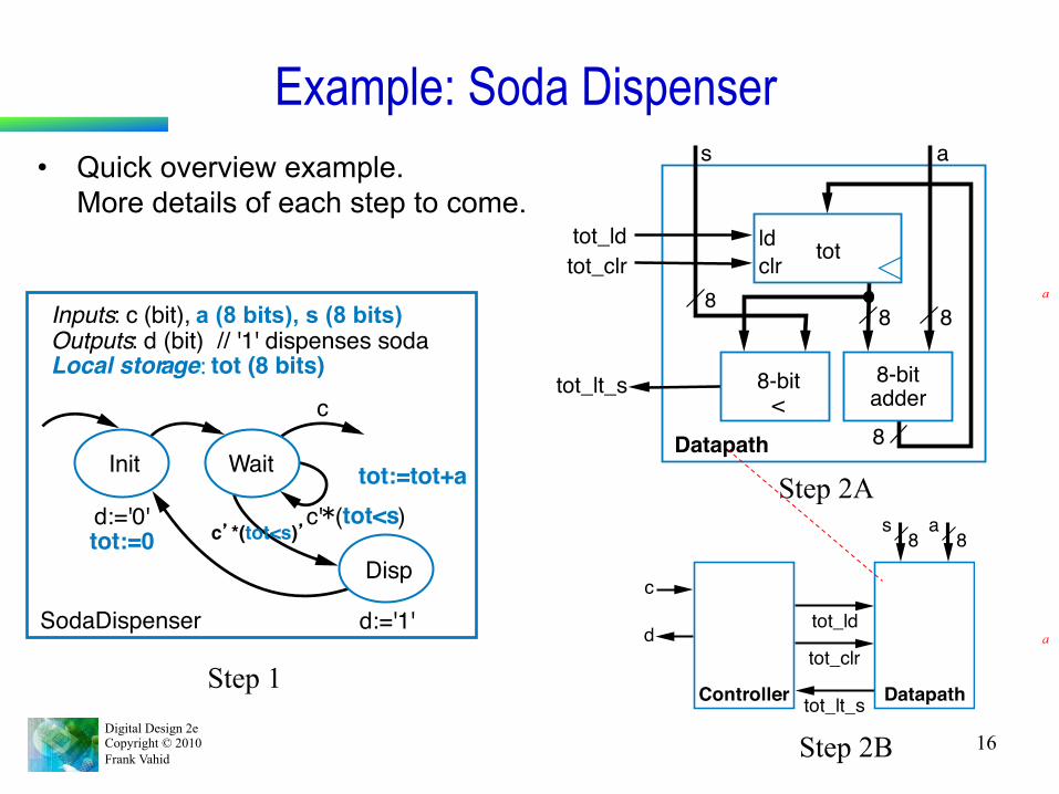
Example: Soda Dispenser • Quick overview example.
More details of each step to come.
Inputs : c (bit), a (8 bits), s (8 bits) Outputs : d (bit) // '1' dispenses soda Local stor a g e : tot (8 bits)
W ait
Disp
Init
d:='0' tot:=0 c’*(tot<s)’ c' * ( tot<s )
d:='1'
c
tot:=tot+a
SodaDispenser
Step 1
Step 2A
8
8
8
s
8
a
Datapath
tot_ld tot_clr
tot_lt_s
ld clr tot
8-bit <
8-bit adder
tot_lt_s
tot_clr
tot_ld
Controller Datapath
s
c
d
a8 8
Step 2B
a
a

Digital Design 2e Copyright © 2010 Frank Vahid
17
Example: Soda Dispenser • Quick overview example.
More details of each step to come.
Inputs : c (bit), a (8 bits) , s (8 bits) Outputs : d (bit) // '1' dispenses soda Local stor a g e : tot (8 bits)
W ait
Disp
Init
d:='0' tot:=0 c’*(tot<s)’ c' * ( tot<s )
d:='1'
c
tot:=tot+a
SodaDispenser
Step 1
tot_lt_s
tot_clr
tot_ld
Controller Datapath
s
c
d
a8 8
Step 2B
Step 2C
Inputs : c, tot_lt_s (bit) Outputs : d, tot_ld , tot_clr (bit)
Wait
Disp
Init d=0
tot_clr=1 c' * tot_lt_s’ c ʹ′ * tot_lt_s
d=1
c
tot_ld=1
c d
tot_ld tot_clr tot_lt_s
Controller
Add

Digital Design 2e Copyright © 2010 Frank Vahid
18
Example: Soda Dispenser • Quick overview example.
More details of each step to come.
Step 2C
Inputs : c, tot_lt_s (bit) Outputs : d, tot_ld , tot_clr (bit)
Wait
Disp
Init d=0
tot_clr=1 c ʹ′ * tot_lt_s
ʹ′
c ʹ′ * tot_lt_s
d=1
c
tot_ld=1
c d
tot_ld tot_clr tot_lt_s
Controller
Add
d000000000
1
000000001
0
111100000
0
n0111111001
0
n1000010110
0
010101010
0
c001100110
0
s1000000001
1
s0000011110
1
tot_lt_s
tot_ld
tot_clr
Init
Wait
Add
Disp
Use controller (Finite State Machine) design process to complete the design
a

Digital Design 2e Copyright © 2010 Frank Vahid
19
RTL Design Process—Step 2A: Create a datapath • Sub-steps
– HLSM data inputs/outputs à Datapath inputs/outputs. – HLSM local storage item à Instantiated register
• "Instantiate": Add new component ("instance") to design – Each HLSM state action and transition condition data computation à
Datapath components and connections • Also instantiate multiplexors as needed
• Need component library from which to choose
A B S
add reg Q I
ld clr A B
lt cmp eq gt
mux2x1 Q
I 1 s0
I 0
S = A+B (unsigned) A<B: lt=1 A=B: eq=1 A>B: gt=1
s0=0: Q= I 0 s0=1: Q= I 1
clk^ and clr=1: Q=0 clk^ and ld=1: Q= I else Q stays same
shift<L/R> I
Q
shiftL1: <<1 shiftL2: <<2 shiftR1: >>1 ...

Digital Design 2e Copyright © 2010 Frank Vahid
20
Step 2A: Create a Datapath—Simple Examples
Preg Q I
ld clr
A B S add2
A B S add1
X Y Z (a)
Preg = X + Y + Z
X + Y
X + Y + Z
X Y Z
P
0 1
Preg
P DP
Preg = Preg + X
X
P
Preg
Preg Q I
ld clr
A B S add1
X (b)
0 1
P
DP
Preg=X+Y; regQ=Y+Z
X Y Z
P Preg
Q regQ
Preg Q I
ld clr
A B S add2 A B
S add1
X Y (c)
0 1
P
regQ Q I
ld clr 0 1
Q
Z DP
k=0: Preg = Y + Z k=1: Preg = X + Y
X Y Z
P Preg
Preg Q I
ld clr
A B S add2 A B
S add1
X Y (d)
0 1
P
Z
mux2x1 Q
I 1 s0
I 0
k
k
DP
a

Digital Design 2e Copyright © 2010 Frank Vahid
21
Laser-Based Distance Measurer—Step 2A: Create a Datapath
• HLSM data I/O à DP I/O • HLSM local storage à reg • HLSM state action and
transition condition data computation à Datapath components and connections
a
S0 S1 S2 S3
L := '0'Dreg := 0
L := '1' L := '0'Dctr := Dctr+1
Dreg := Dctr/2// calculate D
Dctr := 0
B' S'
B SS4
Inputs: B (bit), S (bit) Outputs: L (bit), D (16 bits)DistanceMeasurerLocal storage: Dreg, Dctr (16 bits)
Datapath
Dreg_clr Dreg_ld Dctr_clr Dctr_ld
clr ld
Q
I Dreg: reg(16)
A B S Add1: add(16)
clr ld
Q Dctr: reg(16)
I
1 16
16 Shr1: shiftR1(16)
I Q
16
16
16 D

Digital Design 2e Copyright © 2010 Frank Vahid
22
Laser-Based Distance Measurer—Step 2B: Connecting the Datapath to a Controller
D
B L
S
16 to display
from button Controller
to laser from sensor
Dreg_clr Dreg_ld
Dctr_clr
Dctr_ld
Datapath
300 MHz Clock a
Digital Design 2e Copyright © 2010 Frank Vahid
23
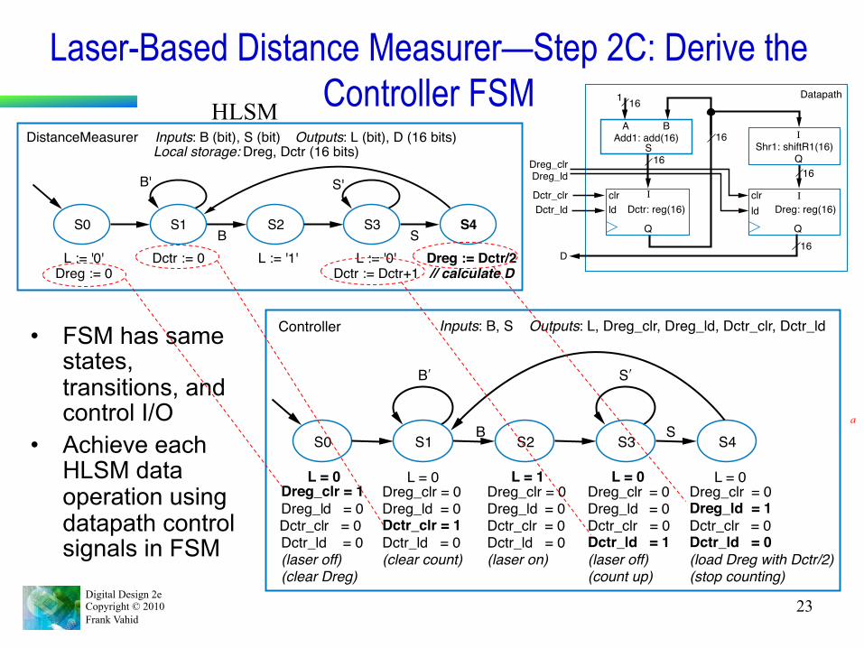
Laser-Based Distance Measurer—Step 2C: Derive the Controller FSM
• FSM has same states, transitions, and control I/O
• Achieve each HLSM data operation using datapath control signals in FSM
S0 S1 S2 S3
L := '0'Dreg := 0
L := '1' L := '0'Dctr := Dctr+1
Dreg := Dctr/2// calculate D
Dctr := 0
B' S'
B SS4
Inputs: B (bit), S (bit) Outputs: L (bit), D (16 bits)DistanceMeasurerLocal storage: Dreg, Dctr (16 bits)
Inputs : B, S Outputs : L, Dreg_clr, Dreg_ld, Dctr_clr, Dctr_ld
S0 S1 S2 S3 L = 0 L = 1 L = 0 L = 0
B ʹ′ S ʹ′
B S S4
Dreg_clr = 1 Dreg_l d = 0 Dctr_cl r = 0 Dctr_ld = 0 (laser off ) (clear Dreg)
Dreg_clr = 0 Dreg_ld = 0 Dctr_clr = 0 Dctr_ld = 1 (laser off) (count up)
Dreg_clr = 0 Dreg_ld = 0 Dctr_clr = 1 Dctr_ld = 0 (clear count)
L = 0 Dreg_clr = 0 Dreg_ld = 1 Dctr_clr = 0 Dctr_ld = 0 (load Dreg with Dctr/2) (stop counting)
Dreg_clr = 0 Dreg_ld = 0 Dctr_clr = 0 Dctr_ld = 0 (laser on)
Controller
clrld
clrld
Q Q
IDctr: reg(16) Dreg: reg(16)
16
16
D
Datapath
Dreg_clr
Dctr_clrDctr_ld
Dreg_ld
Shr1: shiftR1(16)
A B
SAdd1: add(16)
I
1
16
16
16
I
Q
HLSM
a

Digital Design 2e Copyright © 2010 Frank Vahid
24
Laser-Based Distance Measurer—Step 2C: Derive the Controller FSM
• Same FSM, using convention of unassigned outputs implicitly assigned 0
Inputs: B, S Outputs: L, Dreg_clr, Dreg_ld, Dctr_clr, Dctr_ld
S0 S1 S2 S3
L = 0 L = 1 L = 0
B¢ S¢
B S
Dreg_clr = 1(laser off)(clear Dreg)
Dctr_ld = 1(laser off)(count up)
Dctr_clr = 1(clear count)
Dreg_ld = 1Dctr_ld = 0(load Dreg with Dctr/2)(stop counting)
(laser on)
S4
Controller
Some assignments to 0 still shown, due to their importance in understanding desired controller behavior

Digital Design 2e Copyright © 2010 Frank Vahid
25
More RTL Design • Additional datapath components
5.4
A B
Ssub
S = A-B(signed)
upcntQ
incclr
clk^ and clr=1: Q=0clk^ and inc=1: Q=Q+1else Q stays same
A B
Pmul
P = A*B(unsigned)
RF
R_d
W_eW_a
W_d
R_eR_a
clk^ and W_e=1: RF[W_a]= W_dR_e=1: R_d = RF[R_a]
A
Qabs
Q = |A|(unsigned)
(signed)

Digital Design 2e Copyright © 2010 Frank Vahid
26
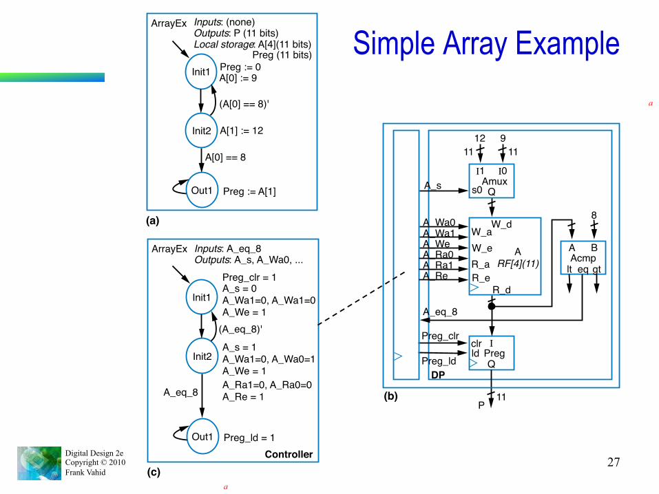
RTL Design Involving Register File or Memory • HLSM array: Ordered list of items
– Ex: Local storage: A[4](8-bit) – 4 8-bit items – Accessed using notation "A[i]", i is index – A[0] := 9; A[1] := 8; A[2] := 7; A[3] := 22
• Array contents now: <9, 8, 7, 22> • X := A[1] will set X to 8 • Note: First element's index is 0
• Array can be mapped to instantiated register file or memory
Digital Design 2e Copyright © 2010 Frank Vahid
27
Simple Array Example
Preg Q I
ld clr
P
Preg_clr Preg_ld
DP (b) 11
A RF[4](11)
R_d
W_e W_a W_d
R_e R_a
Amux Q
I 1 s0
I 0
9 12
A_Wa0 A_Wa1 A_We A_Ra0 A_Ra1 A_Re
A_s
11 11
A B lt Acmp
eq gt
8
A_eq_8
Controller (c)
Init1
Init2
Out1
A_s = 0 A_Wa1=0, A_Wa1=0 A_We = 1
Preg_ld = 1
ArrayEx Inputs : A_eq_8 Outputs : A_s, A_Wa0, ...
A_s = 1 A_Wa1=0, A_Wa0=1 A_We = 1
A_eq_8
(A_eq_8)'
Preg_clr = 1
A_Ra1=0, A_Ra0=0 A_Re = 1
(a)
Init1
Init2
Out1
A[0] := 9
Preg := A[1]
ArrayEx Inputs : (none) Outputs : P (11 bits) Local storage : A[4](11 bits)
A[1] := 12 A[0] == 8
(A[0] == 8)'
Preg := 0 Preg (11 bits)
a
a

Digital Design 2e Copyright © 2010 Frank Vahid
28
RTL Example: Video Compression – Sum of Absolute Differences
• Video is a series of frames (e.g., 30 per second) • Most frames similar to previous frame
– Compression idea: just send difference from previous frame
Digitized frame 2
1 Mbyte
Frame 2
Digitized frame 1
Frame 1
1 Mbyte ( a )
Digitized frame 1
Frame 1
1 Mbyte ( b )
Only difference: ball moving
a Difference of 2 from 1
0.01 Mbyte
Frame 2
Just send difference

Digital Design 2e Copyright © 2010 Frank Vahid
29
RTL Example: Video Compression – Sum of Absolute Differences
• Need to quickly determine whether two frames are similar enough to just send difference for second frame – Compare corresponding 16x16 “blocks”
• Treat 16x16 block as 256-byte array – Compute the absolute value of the difference of each array item – Sum those differences – if above a threshold, send complete frame
for second frame; if below, can use difference method (using another technique, not described)
Frame 2 Frame 1 compare Each is a pixel, assume represented as 1 byte (actually, a color picture might have 3 bytes per pixel, for intensity of red, green, and blue components of pixel)
Digital Design 2e Copyright © 2010 Frank Vahid
30
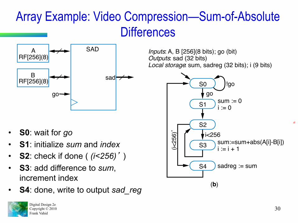
Array Example: Video Compression—Sum-of-Absolute Differences
a
!go
(i<25
6)’
S0
S1
S2
S3
S4
go sum := 0 i := 0
i<256 sum:=sum+abs(A[i]-B[i]) i := i + 1
sadreg := sum
( b )
Inputs : A, B [256](8 bits); go (bit) Outputs : sad (32 bits) Local storage : sum, sadreg (32 bits); i (9 bits)
A RF[256](8)
go
SAD
sad B RF[256](8)
• S0: wait for go • S1: initialize sum and index • S2: check if done ( (i<256)’ ) • S3: add difference to sum,
increment index • S4: done, write to output sad_reg
Digital Design 2e Copyright © 2010 Frank Vahid
31
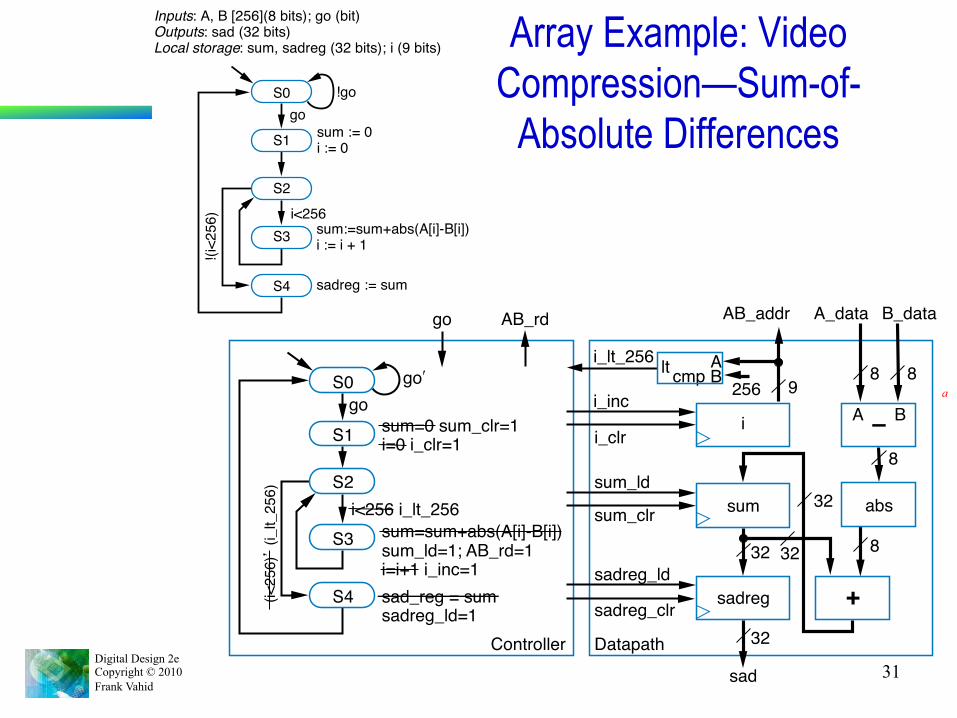
Array Example: Video Compression—Sum-of-
Absolute Differences !go
!(i<2
56)
S0
S1
S2
S3
S4
gosum := 0i := 0
i<256sum:=sum+abs(A[i]-B[i])i := i + 1
sadreg := sum
Inputs: A, B [256](8 bits); go (bit)Outputs: sad (32 bits)Local storage: sum, sadreg (32 bits); i (9 bits)
S0
S1
S2
S3
S4
go ʹ′ go
go AB_rd
sum=0 sum_clr=1 i=0 i_clr=1
i<256 i_lt_256
(i<25
6)’ (i
_lt_
256)
sum=sum+abs(A[i]-B[i]) sum_ld=1; AB_rd=1 i=i+1 i_inc=1 sad_reg = sum sadreg_ld=1
Controller
a
i_lt_256
i_inc i_clr
sum_ld sum_clr
sadreg_ld
Datapath
sum
sadreg
sad
AB_addr A_data B_data
cmp 9
32
8
8
8 8
32 32
32
i –
+
abs
sadreg_clr
lt 256
A B
A B

Digital Design 2e Copyright © 2010 Frank Vahid
32
Circuit vs. Microprocessor • Circuit: Two states (S2 & S3) for each i, 256 i’sà 512 clock cycles • Microprocessor: Loop (for i = 1 to 256), but for each i, must move
memory to local registers, subtract, compute absolute value, add to sum, increment i – say 6 cycles per array item à 256*6 = 1536 cycles
• Circuit is about 3 times (300%) faster (assuming equal cycle lengths)
S3 sum:=sum+abs(A[i]-B[i]) i:=i+1
S2 i<256
(i<256)’

Digital Design 2e Copyright © 2010 Frank Vahid
33
Data Dominated RTL Design Example • Data dominated design: Extensive DP,
simple controller • Control dominated design: Complex
controller, simple DP • Example: Filter
– Converts digital input stream to new digital output stream
– Ex: Remove noise • 180, 180, 181, 180, 240, 180, 181 • 240 is probably noise, filter might replace
by 181 – Simple filter: Output average of last N
values • Small N: less filtering • Large N: more filtering, but less sharp
output
1212Y
clk
Xdigital filter

Digital Design 2e Copyright © 2010 Frank Vahid
34
Data Dominated RTL Design Example: FIR Filter • FIR filter
– “Finite Impulse Response” – Simply a configurable weighted
sum of past input values – y(t) = c0*x(t) + c1*x(t-1) + c2*x(t-2)
• Above known as “3 tap” • Tens of taps more common • Very general filter – User sets
the constants (c0, c1, c2) to define specific filter
• RTL design – Step 1: Create HLSM
• Very simple states/transitions
12 12 Y
clk
X digital filter
y(t) = c0*x(t) + c1*x(t-1) + c2*x(t-2)
Init FC
Yreg := c0*xt0 + c1*xt1 + c2*xt2xt0 := Xxt1 := xt0xt2 := xt1
Yreg := 0xt0 := 0xt1 := 0xt2 := 0c0 := 3c1 := 2c2 := 2
Local storage: xt0, xt1, xt2, c0, c1, c2 (12 bits);Inputs: X (12 bits) Outputs: Y (12 bits)
FIR filter
Yreg (12 bits)
Assume constants set to 3, 2, and 2

Digital Design 2e Copyright © 2010 Frank Vahid
35
FIR Filter • Step 2A: Create datapath
• Step 2B: Connect Ctrlr/DP (as earlier examples)
• Step 2C: Derive FSM – Set clr and ld lines appropriately
xt0 xt1 xt2
x(t-2)x(t-1)x(t)
Datapath for 3-tap FIR filter
X
Y
clk
c0 c1 c2
* *
+
*
+Yreg
Yreg_ld
c0_ld c1_ld c2_ld
xt0_ld
xt0_clr
... ...
Yreg_clr
3 2 2
12
12
Init FC
Yreg := c0*xt0 + c1*xt1 + c2*xt2xt0 := Xxt1 := xt0xt2 := xt1
Yreg := 0xt0 := 0xt1 := 0xt2 := 0c0 := 3c1 := 2c2 := 2
Local storage: xt0, xt1, xt2, c0, c1, c2 (12 bits);Inputs: X (12 bits) Outputs: Y (12 bits)
FIR filter
Yreg (12 bits)

Digital Design 2e Copyright © 2010 Frank Vahid
36
Circuit vs. Microprocessor • Comparing the FIR circuit to microprocessor instructions
– Microprocessor • 100-tap filter: 100 multiplications, 100 additions. Say 2 instructions
per multiplication, 2 per addition. Say 10 ns per instruction. • (100*2 + 100*2)*10 = 4000 ns
– Circuit • Assume adder has 2 ns delay, multiplier has 20 ns delay • Longest path goes through one multiplier and two adders
– 20 + 2 + 2 = 24 ns delay • 100-tap filter, following design on previous slide, would have about a
34 ns delay: 1 multiplier and 7 adders on longest path – Circuit is more than 100 times faster (4000/34). Wow.
y(t) = c0*x(t) + c1*x(t-1) + c2*x(t-2)

Digital Design 2e Copyright © 2010 Frank Vahid
37
Determining Clock Frequency • Designers of digital circuits
often want fastest performance – Means want high clock
frequency • Frequency limited by longest
register-to-register delay – Known as critical path – If clock is any faster, incorrect
data may be stored into register – Longest path on right is 2 ns
• Ignoring wire delays, and register setup and hold times, for simplicity
5.5
a
+
b
c
2 ns del a y
clk

Digital Design 2e Copyright © 2010 Frank Vahid
38
Critical Path • Example shows four paths
– a to c through +: 2 ns – a to d through + and *: 7 ns – b to d through + and *: 7 ns – b to d through *: 5 ns
• Longest path is thus 7 ns • Fastest frequency
– 1 / 7 ns = 142 MHz
a
+ *
c d
5 ns del a y
2 ns del a y
Max (2,7,7,5) = 7 ns
a b
2 ns
2 ns
7 ns
7
ns

Digital Design 2e Copyright © 2010 Frank Vahid
39
Critical Path Considering Wire Delays • Real wires have delay too
– Must include in critical path • Example shows two paths
– Each is 0.5 + 2 + 0.5 = 3 ns • Trend
– 1980s/1990s: Wire delays were tiny compared to logic delays
– But wire delays not shrinking as fast as logic delays
• Wire delays may even be greater than logic delays!
• Must also consider register setup and hold times, also add to path
• Then add some time to the computed path, just to be safe – e.g., if path is 3 ns, say 4 ns instead
a
a
+
b
c
2 ns
0.5 ns 0.5 ns
0.5 ns
clk
3 ns
3 ns

Digital Design 2e Copyright © 2010 Frank Vahid
40
A Circuit May Have Numerous Paths • Paths can exist
– In the datapath – In the controller – Between the
controller and datapath
– May be hundreds or thousands of paths
• Timing analysis tools that evaluate all possible paths automatically very helpful
Combinational logic
c tot_lt_s
clk
n1
d tot_ld
tot_lt_s
t ot_clr
s0 s1
n0
State register
s
8 8
8
8
a
ld clr tot
Datapath
8-bit <
8-bit adder
( a )
( c )
( b ) a
Related Documents