Introduction 1 ECE 4890 Fall 2012: Design Project RFPs Revised 10/25/2012 Introduction This document contains inputs received from the outside sponsors, faculty members, and other in- terested parties, with regard to senior design project ideas. The names of the submitters is available by request. When you have formed a possible design team, request project contact information from Dr. Wickert, and proceed to interview the submitter/customer for more details, and perhaps the formation of a preliminary requirements specification. As more RFPs are submitted to me, they will be integrated into this document. Check back for additions and changes. RFPs Project 1: BLE Prototypes for Interface Testing with an iOS Device Problem Statement Since October 2011, mass market mobile devices have started including Bluetooth Low Energy chipsets. This represents a substantial opportunity for hardware and device manufacturers and will advance the use of wireless sensor arrays in consumer applications. The purpose of this project is to create two Bluetooth Low Energy prototype products, to charac- terize key performance metrics of the products, and to wirelessly connect the products to an Apple iOS-based device. Project Need First, the student team must design a custom Printed Circuit Board using Eagle software that houses a Bluetooth Low Energy radio and an ultrasonic sensor. The board shall not exceed 1.5” x 1.5” square and must contain a rechargeable battery compatible with Texas Instrument’s induction charging system. The team must use Nordic Semiconductor’s nRF51822 integrated BLE radio with ARM Core. The team will design a schematic and layout that encompasses these parts into a full-custom design. The team will create a second board with identical requirements but housing a small DC motor. Both products will require a full custom schematic design. Second, the student team must characterize key performance metrics of the products, including battery life as it relates to sample rate, BLE radio link latency, antenna strength as it relates to dis- tance, accuracy of the ultrasonic sensor, and torque characteristics of the chosen motor. Third, the student team must wirelessly connect both products to an Apple iOS-based mobile de- vice. The student teams will generate a test application that will be used to help characterize the key metrics. Each product requires the student team to generate distinct SDKs that would provide high-level developer access to the two products.

Welcome message from author
This document is posted to help you gain knowledge. Please leave a comment to let me know what you think about it! Share it to your friends and learn new things together.
Transcript

Introduction 1
ECE 4890 Fall 2012: Design Project RFPsRevised 10/25/2012
IntroductionThis document contains inputs received from the outside sponsors, faculty members, and other in-terested parties, with regard to senior design project ideas. The names of the submitters is available by request. When you have formed a possible design team, request project contact information from Dr. Wickert, and proceed to interview the submitter/customer for more details, and perhaps the formation of a preliminary requirements specification.
As more RFPs are submitted to me, they will be integrated into this document. Check back for additions and changes.
RFPs
Project 1: BLE Prototypes for Interface Testing with an iOS Device
Problem StatementSince October 2011, mass market mobile devices have started including Bluetooth Low Energy chipsets. This represents a substantial opportunity for hardware and device manufacturers and will advance the use of wireless sensor arrays in consumer applications.
The purpose of this project is to create two Bluetooth Low Energy prototype products, to charac-terize key performance metrics of the products, and to wirelessly connect the products to an Apple iOS-based device.
Project NeedFirst, the student team must design a custom Printed Circuit Board using Eagle software that houses a Bluetooth Low Energy radio and an ultrasonic sensor. The board shall not exceed 1.5” x 1.5” square and must contain a rechargeable battery compatible with Texas Instrument’s induction charging system. The team must use Nordic Semiconductor’s nRF51822 integrated BLE radio with ARM Core. The team will design a schematic and layout that encompasses these parts into a full-custom design. The team will create a second board with identical requirements but housing a small DC motor. Both products will require a full custom schematic design.
Second, the student team must characterize key performance metrics of the products, including battery life as it relates to sample rate, BLE radio link latency, antenna strength as it relates to dis-tance, accuracy of the ultrasonic sensor, and torque characteristics of the chosen motor.
Third, the student team must wirelessly connect both products to an Apple iOS-based mobile de-vice. The student teams will generate a test application that will be used to help characterize the key metrics. Each product requires the student team to generate distinct SDKs that would provide high-level developer access to the two products.

RFPs 2
As a stretch goal, the team will combine two of the motor products and one of the ultrasonic prod-ucts to create a simple robot that may be driven by an Apple iOS-based mobile device.
Team MakeupThe company will provide access to nRF51822 Evaluation Boards and the Apple iOS SDK. Stu-dents should be able to use the free version of Eagle PCB as their CAD tool. A budget will be given to the teams to support purchasing components, having custom PCBs fabricated, and having surface mount performed.
The team should consist of at least a single Electrical Engineering student with hardware develop-ment skills, a single Electrical engineering student with firmware development skills, and a Com-puter Engineering student with interest in taking “starter code” provided by the company to build a full-custom iOS application.
Project 2: Micro Position Controller
Project DescriptionThe system required is a microcontroller/driver system used to remotely operate stepping motor-driven automatic probe/antenna connivance. The system is used to measure the performance of anechoic and semi-anechoic chambers used by commercial and government users. (See block diagram for general overview of the system.) A fully anechoic chamber is used to design antennas and measure RCS (radar cross section), whereas semi-anechoic chambers are a controlled envi-ronment used to measure the EMI (electromagnetic interference) potentially generated by com-mercial electronic devices. The system controls positioning in two axes. (Three-axis control may be desired for future uses.) The various positioning track/masts and carriages are mostly dielectric/low-reflective materials (such as plastic and fiberglass) interchangeable with the Micro Position Controller positioning system.
Specifications/Requirements
• System Controller – An assembly consisting of microcontroller, axis drivers (for supplying power stepping motors) and a dc power supply.
• Control communications from the laptop to the system controller consists of fiber optic inter-face link, with the system controller being located in a remote location. The system controller is used to power and actuate one of a number of dual axis positioning systems used to re-motely control RF shielded anechoic chamber performance measurements. Control software on the laptop is written in LabVIEW. A USB-to-serial converter connects the laptop to the fiber optic link.
• PC/Fiber optic modem is a standard USB Fiber optic modem available “off the shelf” from a company like National Instruments. The fiber optic connectors should be of common industry standard. The fiber optic cable should be above average quality and strength as it is used in rugged environments and repeatedly used, but fully dielectric.
• Cabling- Cable from system controller to positioning hardware should be as small gauge as possible using high reliability connectors- “Cannon” plug type.

RFPs 3
• The system should be ultra reliable, ruggedized, and as compact as possible. The system is transported and shipped in shipping cases around the world, so nothing can be delicate. It should be as simple as practical.
• When the system is in use, it will be slaved to computer control. During set up and trouble-shooting, it is important to be able to control the system from within the anechoic chamber, independent from the laptop. A hand held keypad is suggested, but a small netbook or touch screen/pad can be considered. The system service must be non-interrupted when switching from keypad (inside anechoic chamber) to computer control (inside control room).
• Motion control software may reside in the laptop, and is uploaded to the system control-ler at startup or may reside in the controller, whichever is most reliable. At a minimum, the controller should have the ability to accept simple commands like a specific (x,y) coordinate to move to. A simple program would move the motors to a pre-specified location, wait for a command, then move to the next pre-specified position. This maintains consistency across different tests, as well as simplifying the test procedure and/or laptop software, e.g., com-mand can be “MOVE” to go to the next position rather than “GOTO (x,y)” where x and y change at each position.
• Consideration should be given to the suppression of RF interference from the system control-ler and cabling. As the motors draw high current, strong EMI may be generated.
Tentative budget is $3000.
Project 3: Verilog Linting ToolA linting tool is a tool that checks that a verilog design can be synthesized, simulated, tested, and adheres to company specified coding guidelines. A verilog design that is synthesizable can be translated to gates and implemented in an ASIC or FPGA. Testbenches are typically not synthesiz-able.
An example of a commercial linting tool is Synopsys’s Leda RTL Checker. Details on Leda can be found at http://www.synopsys.com/tools/verification/functionalveri-fication/pages/leda.aspx. UCCS has Leda installed on the Linux server LATS2.
Project NeedStudents in the ECE 4242/5242 Advanced Digital Design Methodology course often find that their coding style is not synthesizable and does not adhere to coding guidelines like number of com-ments, usage of the compiler directive. ̀ default_nettype none, etc. When they take a follow on course to ECE 4242/5242 like 4200 Advanced Digital Design Methodology lab or 4211/5211 Rapid Prototyping with FPGA’s they often find that their designs have to be completely rewritten to be synthesizable. It is desired to provide this feedback earlier in the ECE 4242/5242 class.
Project DescriptionThis project involves creating a linting tool to check for synthesizability and adherence to coding guidelines. The tool should be able to be used on a windows based PC using only a minimum of freely available software. Portability to a Linux based OS would be a plus. The tool is intended
RFPs 4
to be installed on any machine that students create their design on. This could be a personal PC, RATS, or the machines in EN229 or EN233. A web-based tool might be a good solution.
There are 3 main tasks to this project:
1. Create the linting tool2. Create test cases for the linting tool. These test cases will be written in verilog and will contain
code that should pass or fail when the linting tool is run on them as well as expected output.3. Create a testing environment that will run the test cases created in 2 and compare the output
(i.e. warnings/errors) of the linting tool against expected output.
Team MakeupThe team should be made up of at least 1 computer engineer with strong software skills. A team of size 2 is appropriate, but 3 can also be accomodated. The team members need to have earned a B or better in ECE 4242 and should preferably be taking or have taken 4200 and/or 4211/5211.
Project 4: Solar-Powered BLE Weather Station
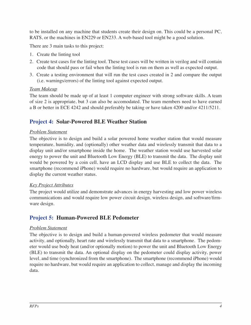
Problem StatementThe objective is to design and build a solar powered home weather station that would measure temperature, humidity, and (optionally) other weather data and wirelessly transmit that data to a display unit and/or smartphone inside the home. The weather station would use harvested solar energy to power the unit and Bluetooth Low Energy (BLE) to transmit the data. The display unit would be powered by a coin cell, have an LCD display and use BLE to collect the data. The smartphone (recommend iPhone) would require no hardware, but would require an application to display the current weather status.
Key Project AttributesThe project would utilize and demonstrate advances in energy harvesting and low power wireless communications and would require low power circuit design, wireless design, and software/firm-ware design.
Project 5: Human-Powered BLE Pedometer
Problem StatementThe objective is to design and build a human-powered wireless pedometer that would measure activity, and optionally, heart rate and wirelessly transmit that data to a smartphone. The pedom-eter would use body heat (and/or optionally motion) to power the unit and Bluetooth Low Energy (BLE) to transmit the data. An optional display on the pedometer could display activity, power level, and time (synchronized from the smartphone). The smartphone (recommend iPhone) would require no hardware, but would require an application to collect, manage and display the incoming data.
RFPs 5
Key Project Attributes The project would utilize and demonstrate advances in energy harvesting and low power wireless communications and would require low power circuit design, wireless design, and software/firm-ware design.
Project 6: Wireless Shelf Display
Problem StatementThe objective is to design and build a shelf labelling system that uses long range battery-assisted passive UHF RFID to display product pricing and product information. The shelf unit would in-clude an RFID chip to communicate with a host/reader system, a microcontroller and a low power display. The RFID chip could also be used to harvest energy from the RFID reader (and/or dedi-cated charger) field so that the product would not require traditional (non-green) batteries to power the display. A supercapacitor or other energy storage technology could be used. The reader system would send data to the display and collect diagnostic status from the display (i.e. error status and/or stored energy level/low battery).
Key Project AttributesThe project would utilize and demonstrate advances in energy harvesting and long range RFID and would require low power circuit design, wireless design, and software/firmware design.
Project 7: Remote Operation of Battery Lab Thermal Chambers
Problem StatementThe High-Capacity Battery Research and Controls Laboratory (HCBRTL) at UCCS houses test and measurement equipment that can be used to gather data from battery cells, modules, and packs in simulated real-world operating environments (cf. http://mocha-java.uccs.edu/HCBRTL). There are presently nine environmental (thermal) chambers in the laboratory, which are used to keep bat-teries at a constant desired ambient temperature during testing.
Each of these chambers is presently operated manually using the front panel on the unit. This is not desirable because it requires that we travel to the laboratory to monitor performance and to change setpoints—we would also like the capability of changing the setpoints and monitoring chamber temperatures remotely. The chambers have serial RS-232 interfaces that can be con-nected to a supervisory computer to enable remote operation.
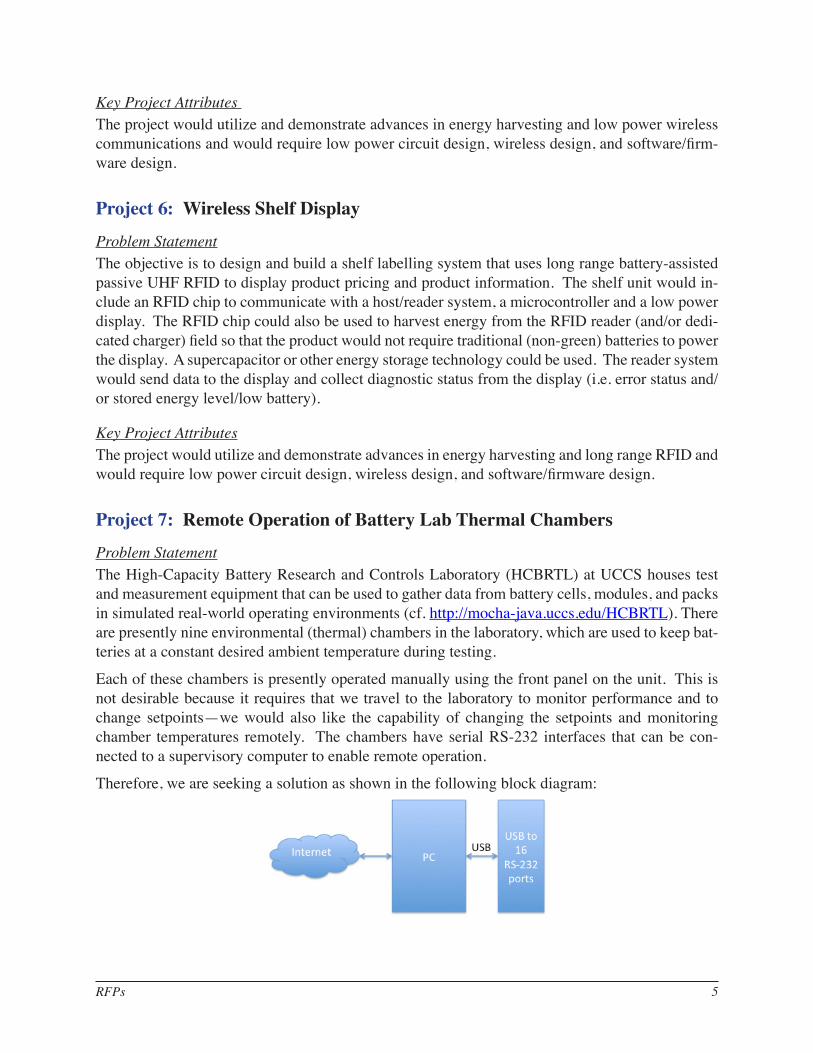
Therefore, we are seeking a solution as shown in the following block diagram:

RFPs 6
The USB interface of a PC will connect to a commercial-off-the-shelf (COTS) USB-to-16-port-serial interface. The ports of this interface will be connected to individual thermal chambers. Software on the PC, written in C# (to be compatible with future plans for the laboratory), will monitor the thermal chamber operating points, and will command the thermal chambers to change their setpoints on user demand.
The PC will also host a web site where the present status of all thermal chambers is presented and continuously updated. The user can log in to this web site remotely, using authenticated login, and change the thermal chamber set points.
There are two major components to the design: (1) the Internet web-page interface to view cur-rent operating conditions and to change setpoints, and (2) the RS-232 chamber interface to query chamber temperatures and to change setpoints. This breakdown works naturally for a two-member team. For a three-member team, there is an additional requirement for an iPod Touch/iPhone HTML5 application that can monitor and operate the chambers.
Specifications
• The solution must work with Watlow 96 thermal-chamber controllers, Watlow F4 thermal-chamber controllers, and EZT-560i thermal-chamber controllers.
• The solution must work with up to 16 different thermal chambers simultaneously.
• The solution must be configurable with a simple text file (stating which ports are used, assign-ing names to chambers on each used port, identifying which thermal-chamber controller type is associated with each port).
• Update rate for all monitored temperatures and setpoints must be at least 0.5 Hz.
• Internet access when changing setpoints and turning a chamber on/off must be secure. Net-work security must not be minimized.
• The code written to monitor and operate the temperature chambers must be written in C# and must operate on a Windows 7 operating system. The PC must use an Apache web server, and all hosted web pages must auto-refresh as data changes.
• The web interface must show all sixteen channels, names of chambers on each channel (if connected), present setpoint for each chamber, present operating temperature for each cham-ber, and must allow changing setpoints and turning chamber on and off.
• iPod Touch/iPhone application for optional third member: Must provide same functionality as web interface, but in an easier-to-use application.
• Stretch goal: Log error/alarm conditions when chamber is operating out of bounds.
Project 8: True Wireless Security Camera
Project AbstractThis project proposal describes a ‘true’ wireless security camera which would be able to relay a video feed over a wireless LAN back to a viewing station. ‘True’ wireless refers to the fact that the camera is not tethered to cables for either power or data transmission. The device could be centered

RFPs 7
upon a small, low powered, computer, powered by a portable power source. It would have the ca-pability to be placed in locations that normal cameras would not be able to reach.
This project will require a multi-disciplinary team to pool their competencies in order to succeed. Below are summarized how different types of expertise can help to make the design a reality.
Electrical EngineeringDesign a power source which will meet the voltage and current needs of the computer with periph-erals. Also, students could design circuitry which would alert the computer that the power source is almost depleted and that it should shut itself down safely. Battery and Solar power could be two possible options.
Computer EngineeringChoose an embedded computer board which meets the needs of the project, taking into account constraints such as available interfaces, ease of programmability, monetary cost, power usage, and performance.
Higher Level SoftwareStudents would need to design software which would interface with the camera device, and stream back data over the wireless connection to another endpoint. The Data Reciever/Controller end-point would also need to run some software to display the video and remote control the device. Experience will be gained in embedded programming, interacting with image data, and designing/selecting a network communications protocol for use in the data transfer.
Computer NetworkingAn understanding of the constraints of wireless networking will help to create a design that has realistic performance requirements. Also, knowledge of the networking stack, including TCP, UDP and IP will aid in designing an efficient communications scheme.

RFPs 8
Cost EstimatesMaterials Estimated Cost (low) Estimated Cost (high)
Embedded computer board $50 $100802.11 Wireless adaptor $20 $70
USB Camera $30 $70Power source materials $80 $200
TOTAL $180 $440
End Product performance goals:
• Image Framerate:
– Minimally: 1 snapshot per second delivered to viewing apparatus.
– Stretch: Real time (or minimally delayed) 30 frames per second video.
• Operation time from a battery source
– Minimally: 1 hour of battery operation.
– Stretch: Maximize the battery life by employing solar cells, or aggressive power saving techniques.
• Camera Distance from Base Station:
– Minimally: Ensure correct operation of the camera up to 50 feet from the nearest access point.
– Stretch: Employ more advanced wireless antennas to increase the reliable transmission distance.
• Image Viewing:
– Minimally: Enable the user to view the output of the system on a device that is located on the same Local Area Network as the camera.
– Stretch: Enable access from any internet enabled device, taking into consideration needs for user authentication and data privacy.
Project 9: Frame Mangler
IntroductionThe smooth operation of network protocols and applications depends upon a reliable network. However, actual networks often exhibit faults. Thus, it is worthwhile to be able to characterize the behavior of a protocol or application in the presence of a faulty network. For example, a protocol or application may have provisions for retransmission, forward error correction (FEC), session re-establishment and the like that are theoretically sound, but robust product verification demands that the efficacy of these protocols be tested empirically as well. However, products that simulate network faults are often large, highly sophisticated, expensive, and difficult to operate. The goal of

RFPs 9
the present project is to create a small, simple, low-cost device to reliably simulate a basic fault in a constrained test environment, such as an office cubicle or small electronics lab.
Requirements1. Support in-line connection between two copper Ethernet links (RJ45/8P8C)2. Support at least 10Mbps full-duplex link speed3. Support sufficient throughput and add sufficiently small latency to allow realistic operation of
network applications4. Able to pass Ethernet frames through the device without changing any bits5. Able to drop incoming frames in at least one direction6. Able to corrupt incoming frames (electrically valid and properly framed, but with altered data)
in at least one direction7. Able to drop or corrupt a user-configured percentage of frames8. Small and light enough to be readily portable9. Substantially cheaper BOM than simply buying a netbook and USB Ethernet adapter
Sample Stretch Goals1. 100Mbps link speed support2. Line-rate operation at 10Mbps (no undesired packet dropping if a 10Mbps link is saturated
with minimum-sized frames)3. Power Over Ethernet pass-through4. Powering the device with Power Over Ethernet or USB for long-term operation5. Selective corruption of user-configured byte ranges within each packet6. Configurable option to regenerate valid Ethernet frame check sequences for corrupted frames
(simulating e.g. a memory fault at OSI Layer 3 or above)7. Pocket-sized enclosure
Project 10: Cloud Control
Project Abstract Routinely in the consumer and commercial world, there are physical devices and events that are desirable to both detect and control. From a consumer perspective, for example, it may be desir-able to detect if one’s garage door is open, or if one’s irrigation system is running, or if there are lights currently turned on or off in one’s home. Furthermore, with that knowledge of the physical state there is often a case where one would like to change that physical state (i.e. turn the lights on/off or open/close a garage door). While these types of remote control systems have been in place for many years (remote garage door openers for example) there have been fewer advancements that bridge the gap between physical devices and the cloud.
The purpose of this project is to create a product/system that bridges the gap between the physical world and the cloud. This allows users of the product to both detect and control devices from a cloud portal from anywhere in the world.

RFPs 10
ProductThe project upon completion will output the following items:
• An IP-enabled device capable of both receiving input from a sensor and relaying this infor-mation to a cloud service and receiving commands from the cloud to perform the action of closing a relay that performs some action in the physical world.
• The cloud-based software capable of both displaying the input from the IP-enabled device and sending commands to the IP-enabled device to close or open the relay.
• Stretch goal: time permitting the project member(s) will write a smart-phone application to interface with the cloud service thus allowing control of the physical state from the users’ smart phone.
Constraints and Design TradeoffsThis project encapsulates a wide variety of design tradeoffs to be decided by the team completing the project. Some of these tradeoffs include power consumption, scope, and cost. Time permitting, the students will face the stretch challenge of dealing with security issues including authentication of the commanding device/user and ensuring secure communication.
Areas of Engineering
• Embedded Systems Design
• Software Development
• Network Communication
• Systems Design
• Security
What the Student GainsThis project provides the student(s) with exposure to wide spectrum of disciplines from low-end embedded device to the cloud. This exposure teaches the student about the challenges that arise with system integration, design tradeoffs, and coordinated team work. In short, this project encapsulates many of the necessary skills needed to be a successful engineer while allowing the student(s) to produce a meaningful and useful product.

RFPs 11
Cloud control concept.
Project 11: Automatic Bird Deflector
Project AbstractBirds, while often beautiful to observe and generally non-destructive, can be an obnoxious pest to homeowners. While many birds nesting near homeowners are often unnoticed, there are certain nesting locations on or near a home that can be both destructive to the home and unsightly. Some examples of these locations include above the front door, in gutters, dryer vents, or in holes pecked into the siding of a home.
The purpose of this project is to design a low-cost, low-power, disposable, and effective automatic bird deflector.
ProductThe product to be produced by the student or students is a small, low powered device capable of detecting motion triggering some audible or visual deterring feedback. For example, the product might detect motion within some short distance and then play a loud noise like a buzzer or an audio clip recording of the bird’s natural predator. The product must be small, low cost, and low power allowing it to be easily concealed and battery powered for extended periods of time (ideally lasting for time on the order of months).
RFPs 12
Constraints and Design TradeoffsThis project encapsulates a wide variety of design tradeoffs including tradeoffs between power, cost, and performance with the ultimate goal of making a viable product. Engineering fields en-capsulated by this project include circuit design, PCB layout, manufacturing, cost analysis, and power analysis.
What the Student GainsThis project provides the student(s) with exposure to product design under the constraints of being both low cost and low power while maintaining functionality with the purpose of creating a usable, useful, and potentially marketable product.
Project 12: Class-D Garage Band Guitar Amp
IntroductionGuitar amplifiers are often heavy, expensive and typically generate a lot of heat. They are increas-ingly manufactured in foreign countries where manufacturing costs are lower. This project is to design a low cost, very high tech amplifier that could be made using simple automatic board as-sembly techniques resulting in a low cost device that can be made in the USA.
Users of traditional guitar amps, based on vacuum tube designs often tout the pure clean sound and dislike the harsh sound of a semiconductor amplifier. They will tell you this as they crank the volume up to the max, push in the ‘overdrive’ button and smash out a big chord. With modern ana-lytical tools we can determine what the characteristics of a ‘traditional’ amp are – how it sounds, how it clips at high levels and so on. We can develop algorithms to simulate that. If the customer wants a sound like vacuum tubes, we can do that.

RFPs 13
ProductThe product will be a demonstration of a class-D fully digital guitar amplifier. It will be based on a commercially available FPGA development board (such as the Digilent Spartan 3 board) and make use of a switching H-bridge output stage. Since this is a demonstration of the technology it need not operate at high power but the design must target at least 1000W.
The requirements section below provides more details.
Areas of EngineeringThis project potentially uses some aspects of each of the following engineering areas:
• Linear electronics design
• Digital electronics design
• RF electronics design (output stage)
• Human factors (the knobs, switches, displays that form the user interface)
• FPGA programming
• Embedded microcontroller programming (in assembler)
• Digital signal processing
• Mechanical design (the case, heat dissipation)
RequirementsWriting solid, testable requirements is a challenge. Some of those listed here might not quite reach those goals.
• The signal processing chain of the amplifier will be entirely digital
• The output stage will be a PWM H-bridge design
• The design should target a sample rate of at least 44.1 kHz (the CD audio standard) with a 16-bit data channel. (See constraints below)
• The prototype output stage will be capable of driving at least 10W RMS into a 4ohm speaker
• RF radiation from the output stage will be designed to achieve FCC requirements for house-hold electronics. (I.e. we don’t want a new radio station)
• The amplifier will support at least one analog line input for a signal of nominal 100 mV RMS
• The amplifier may support an S/PDIF digital input (http://en.wikipedia.org/wiki/S/PDIF)
• The amplifier should provide a line level analog output (100mV RMS) containing the same signal as sent to the digital output stage. (This is to support early testing and comparison with a conventional amp)
• The amplifier may provide an S/PDIF digital output signal containing the same signal as sent to the PWM output stage.
• The digital processing chain will implement DSP modules to provide the following

RFPs 14
• Volume control (required) (goes all the way to 11)
• Bass and treble control (minimum) with a range of +/- 12dB
• Frequency equalizer (optional)
• Overdrive effect (optional)
• Compressor/Limiter (optional)
• Echo (optional)
• Other – at the student’s discretion
• A user interface which makes use of the development board LCD and buttons/switches:
• Volume control
• Tone control (or equalizer control)
• Selection of input source (analog/digital)
• Selection of effects
• (Optional) a FFT spectrum display using the VGA output on the development board
• At least an overload indication using the LCD or an LED
ConstraintsTypical FPGA development boards such as the Digilent Spartan 3 board do not have large FPGAs nor do they support the very high clock speeds necessary for high fidelity. The prototype should strive to achieve the best possible fidelity with the facilities available on the development board. This likely means a low clock speed and a narrower digital data bus. I.e. instead of a 44.1 kHz sample rate and 16 bits, we might accept 20 kHz and 10 bits (or whatever).
Really high output powers require special power supplies, high voltages, high currents and close attention to detail. While the design must target a 1000W final design, the prototype produced here need not produce more than 10W of output to demonstrate the digital principles of the amplifier.
GuidanceThe expected components of the system are shown in the following figure:

RFPs 15
The major functional blocks:
• 100mV analog line input
• S/PDIF digital input
• input selector
• volume control
• tone control(s)
• effects
• 100mV analog line output
• S/PDIF digital output
• PWM output driver
• LCD
• Input switches
• picoblaze microcontrollerTo achieve CD audio quality (44.1 kHz 16-bit) with a PWM design requires a very high clock rate. A PWM H-bridge design which prevents overlap of the driving signals for the arms of the bridge (to avoid high current spikes in the supply lines) may require very fine timing. The Digilent demo board is not capable of clocking the FPGA at 1GHz so some compromise of sample rate and num-ber of data bits is needed. This is a guitar amp so we can afford to lose some fidelity. It may also be worth considering a bass guitar (only) version which does not need the usual 20 kHz top end.
Related Documents