ECAD Import Module User’s Guide

Welcome message from author
This document is posted to help you gain knowledge. Please leave a comment to let me know what you think about it! Share it to your friends and learn new things together.
Transcript
ECAD Import ModuleUser’s Guide

C o n t a c t I n f o r m a t i o n
Visit the Contact COMSOL page at www.comsol.com/contact to submit general inquiries, contact Technical Support, or search for an address and phone number. You can also visit the Worldwide Sales Offices page at www.comsol.com/contact/offices for address and contact information.
If you need to contact Support, an online request form is located at the COMSOL Access page at www.comsol.com/support/case. Other useful links include:
• Support Center: www.comsol.com/support
• Product Download: www.comsol.com/product-download
• Product Updates: www.comsol.com/support/updates
• COMSOL Blog: www.comsol.com/blogs
• Discussion Forum: www.comsol.com/community
• Events: www.comsol.com/events
• COMSOL Video Gallery: www.comsol.com/video
• Support Knowledge Base: www.comsol.com/support/knowledgebase
Part number: CM023601
E C A D I m p o r t M o d u l e U s e r ’ s G u i d e © 1998–2018 COMSOL
Protected by patents listed on www.comsol.com/patents, and U.S. Patents 7,519,518; 7,596,474; 7,623,991; 8,457,932; 8,954,302; 9,098,106; 9,146,652; 9,323,503; 9,372,673; and 9,454,625. Patents pending.
This Documentation and the Programs described herein are furnished under the COMSOL Software License Agreement (www.comsol.com/comsol-license-agreement) and may be used or copied only under the terms of the license agreement.
Support for implementation of the ODB++® Format was provided by Mentor Graphics Corporation pursuant to the ODB++ Solutions Development Partnership General Terms and Conditions. ODB++ is a trademark of Mentor Graphics Corporation.
COMSOL, the COMSOL logo, COMSOL Multiphysics, COMSOL Desktop, COMSOL Server, and LiveLink are either registered trademarks or trademarks of COMSOL AB. All other trademarks are the property of their respective owners, and COMSOL AB and its subsidiaries and products are not affiliated with, endorsed by, sponsored by, or supported by those trademark owners. For a list of such trademark owners, see www.comsol.com/trademarks.
Version: COMSOL 5.4

C o n t e n t s
C h a p t e r 1 : I n t r o d u c t i o n
About this Guide 6
About the ECAD Import Module. . . . . . . . . . . . . . . . . 6
Where Do I Access the Documentation and Application Libraries? . . . . 6
C h a p t e r 2 : I m p o r t i n g E C A D F i l e s
Importing IPC-2581 and ODB++® Files 12
File Formats for Printed Circuit Boards (PCBs) . . . . . . . . . . . 12
Extruding Layers . . . . . . . . . . . . . . . . . . . . . . . 13
Import Settings for IPC-2581 and ODB++® Files . . . . . . . . . . 13
Importing GDS-II Files 20
The GDS-II File Format . . . . . . . . . . . . . . . . . . . . 20
Extruding Layers . . . . . . . . . . . . . . . . . . . . . . . 21
Import Settings for GDS-II Files . . . . . . . . . . . . . . . . . 21
Importing NETEX-G Files 27
The NETEX-G File Format . . . . . . . . . . . . . . . . . . . 27
Creating NETEX-G Files for Import into COMSOL. . . . . . . . . . 27
Extruding Layers . . . . . . . . . . . . . . . . . . . . . . . 29
Import Settings for NETEX-G Files . . . . . . . . . . . . . . . . 29
Meshing an Imported Geometry 35
Troubleshooting ECAD Import 36
Tuning Import Settings. . . . . . . . . . . . . . . . . . . . . 36
Problems when Extruding Layers . . . . . . . . . . . . . . . . . 36
Problems with Several Geometry Objects . . . . . . . . . . . . . 37
C O N T E N T S | 3

4 | C O N T E N T S
C h a p t e r 3 : P r o g r a m m i n g a n d C o m m a n d R e f e r e n c e
Commands Grouped by Function 40
Import . . . . . . . . . . . . . . . . . . . . . . . . . . . 40

1
I n t r o d u c t i o n
Welcome to the ECAD Import Module! This User’s Guide details features and functionality available with the product.
This introductory chapter is About this Guide.
5

Abou t t h i s Gu i d e
This documentation covers the ECAD Import Module.
About the ECAD Import Module
This product extends the functionality of COMSOL Multiphysics by enabling modeling using imported ECAD design files.
The import capabilities cover the GDS II, NETEX-G, ODB++®, and ODB++(X) file formats and include the creation of 3D geometry during the import operation.
Where Do I Access the Documentation and Application Libraries?
A number of internet resources have more information about COMSOL, including licensing and technical information. The electronic documentation, topic-based (or context-based) help, and the application libraries are all accessed through the COMSOL Desktop.
T H E D O C U M E N T A T I O N A N D O N L I N E H E L P
The COMSOL Multiphysics Reference Manual describes all core physics interfaces and functionality included with the COMSOL Multiphysics license. This book also has instructions about how to use COMSOL Multiphysics and how to access the electronic Documentation and Help content.
Opening Topic-Based HelpThe Help window is useful as it is connected to many of the features on the GUI. To learn more about a node in the Model Builder, or a window on the Desktop, click to highlight a node or window, then press F1 to open the Help window, which then displays information
If you are reading the documentation as a PDF file on your computer, the blue links do not work to open an application or content referenced in a different guide. However, if you are using the Help system in COMSOL Multiphysics, these links work to other modules (as long as you have a license), application examples, and documentation sets.
6 | C H A P T E R 1 : I N T R O D U C T I O N

about that feature (or click a node in the Model Builder followed by the Help button ( ). This is called topic-based (or context) help.
To open the Help window:
• In the Model Builder, Application Builder, or Physics Builder click a node or window and then press F1.
• On any toolbar (for example, Home, Definitions, or Geometry), hover the mouse over a button (for example, Add Physics or Build All) and then press F1.
• From the File menu, click Help ( ).
• In the upper-right corner of the COMSOL Desktop, click the Help( ) button.
To open the Help window:
• In the Model Builder or Physics Builder click a node or window and then press F1.
• On the main toolbar, click the Help ( ) button.
• From the main menu, select Help>Help.
A B O U T T H I S G U I D E | 7

Opening the Documentation Window
T H E A P P L I C A T I O N L I B R A R I E S W I N D O W
Each application includes documentation with the theoretical background and step-by-step instructions to create a model application. The applications are available in COMSOL as MPH-files that you can open for further investigation. You can use the step-by-step instructions and the actual applications as a template for your own modeling and applications. In most models, SI units are used to describe the relevant properties, parameters, and dimensions in most examples, but other unit systems are available.
Once the Application Libraries window is opened, you can search by name or browse under a module folder name. Click to view a summary of the application and its properties, including options to open it or a PDF document.
Opening the Application Libraries WindowTo open the Application Libraries window ( ):
To open the Documentation window:
• Press Ctrl+F1.
• From the File menu select Help>Documentation ( ).
To open the Documentation window:
• Press Ctrl+F1.
• On the main toolbar, click the Documentation ( ) button.
• From the main menu, select Help>Documentation.
The Application Libraries Window in the COMSOL Multiphysics Reference Manual.
• From the Home toolbar, Windows menu, click ( ) Applications
Libraries.
• From the File menu select Application Libraries.
To include the latest versions of model examples, from the File>Help menu, select ( ) Update COMSOL Application Library.
8 | C H A P T E R 1 : I N T R O D U C T I O N
C O N T A C T I N G C O M S O L B Y E M A I L
For general product information, contact COMSOL at [email protected].
To receive technical support from COMSOL for the COMSOL products, please contact your local COMSOL representative or send your questions to [email protected]. An automatic notification and case number is sent to you by email.
C O M S O L W E B S I T E S
Select Application Libraries from the main File> or Windows> menus.
To include the latest versions of model examples, from the Help menu select ( ) Update COMSOL Application Library.
COMSOL website www.comsol.com
Contact COMSOL www.comsol.com/contact
Support Center www.comsol.com/support
Product Download www.comsol.com/support/download
Product Updates www.comsol.com/support/updates
Discussion Forum www.comsol.com/community
Events www.comsol.com/events
COMSOL Video Gallery www.comsol.com/video
Support Knowledge Base www.comsol.com/support/knowledgebase
A B O U T T H I S G U I D E | 9

10 | C H A P T E R 1 : I N T R O D U C T I O N

2
I m p o r t i n g E C A D F i l e s
ECAD file formats have been designed to transfer information necessary for the manufacturing of printed circuit boards (PCBs), integrated circuits (ICs) and microelectromechanical systems (MEMS) devices. You can import data from ECAD files to generate geometry for simulation. During the import of an ECAD file geometric objects are generated based on the 2D layouts and stackup information found in the files.
In this section:
• Importing IPC-2581 and ODB++® Files
• Importing GDS-II Files
• Importing NETEX-G Files
• Meshing an Imported Geometry
• Troubleshooting ECAD Import
11

12 | C H A P T E R
Impo r t i n g I P C - 2581 and ODB++® F i l e s
In this section:
• File Formats for Printed Circuit Boards (PCBs)
• Extruding Layers
• Import Settings for IPC-2581 and ODB++® Files
File Formats for Printed Circuit Boards (PCBs)
The IPC-2581 and OBD++® file formats can handle most of the information needed to manufacture a PCB. For generating a geometry for simulation only some of this information is needed, such as the layout of copper layers, the board outline, and layer stackup information.
An ECAD file for PCBs may also include layers with 2D layouts that specify, for example, the vias and component outlines on the board. You can also import these layers. In a file, the 2D layouts consist of shapes, also called symbols that build the geometry of copper traces and pads. A large number of symbols are specified by the supported PCB formats, for example, lines, circles, rectangles, and surfaces to name a few.
T H E O D B + + ® F O R M A T
ODB++ exists in two different format versions:
• A directory structure with several files, each containing parts of information about the PCB. An entire PCB layout is often distributed as zipped or unzipped tar archives.
• A single XML file containing all information organized in a hierarchy of XML tags. This file format is usually referred to as ODB++(X).
2 : I M P O R T I N G E C A D F I L E S

The ODB++ import reads the layer list and the first step in the file. From the first step the layer features and the board outline are extracted, but the package information is skipped. Multiple step files are not supported.
Extruding Layers
To obtain a 3D geometry for the board the 2D layouts from the ODB++ file archive are extruded, according to the layer stackup information, using one of two methods. A special extrude operation can automatically connect the imported layers to generate a single geometry object after the import. The extruded layers correspond to domains in the resulting object. If the 2D layouts are such that the special extrude algorithm cannot be used a second method is available that performs several extrude operations to generate one geometry object per layer. See how to select the import method in Grouping of Geometries.
Import Settings for IPC-2581 and ODB++® Files
To add an Import node, from the Home or Geometry toolbar, click Import ( ). In the Import section of the Settings window, set the type of file to import to ECAD file. You can also skip this step as the type of the selected file is automatically recognized by the code. Click Browse to locate the file to import, or enter the path to the file. Before clicking the Import button consider to review and configure the import options, especially the layer thickness information, since in many cases the IPC-2581 files and ODB++ archives do not include all necessary information to construct a 3D geometry.
The length unit in the file is detected and displayed in the Settings window. To use the unit in the file as the length unit for the geometry sequence select the Update geometry
unit check box. The check box is selected by default if the Import node is added as the first node in the geometry sequence. The length unit of the geometry sequence is set to inch when the length unit mil is detected in the selected file.
Microwave Filter on PCB: Application Library path RF_Module/Filters/
pcb_microwave_filter_with_stress
I M P O R T I N G I P C - 2 5 8 1 A N D O D B + + ® F I L E S | 13

14 | C H A P T E R
G R O U P I N G O F G E O M E T R I E S
To determine the extrusion method used for generating the 3D geometry from the 2D layouts select one of the available alternatives from the Grouping of geometries list:
• All. This alternative is available only in 3D. The import algorithm extrudes in one operation all imported copper and dielectric layers into a single 3D geometric object. From each copper layer, the imported symbols, such as lines, pads, and surfaces, are combined before extrusion. The copper and dielectric layers become domains in the resulting object. To be able to connect the layers, the algorithm requires that the 2D layouts fulfill certain rules. If the import fails, switch to the By
layer grouping option.
• By layer. Use this alternative to extrude each layer separately. The imported symbols, such as lines, pads, or surfaces, from the copper layers are combined before extrusion. Several geometric objects, one for each imported copper and dielectric layer, are output by the import.
• No grouping. Use this alternative to import and extrude individually each symbol from the copper layers. The import results in separate objects for imported symbols and dielectric layers.
When using the No grouping alternative you have the option to import line symbols as curve objects by selecting the Ignore line width check box.
Note: Using the ignore line width option you can construct geometric objects for components on the board from the information on layers with component outlines. To do this configure an Import node to import only the component outline layer. Select the No grouping method, and the Ignore line width check box. Also select the Manual control of elevations check box, and set the elevation to an appropriate value, but keep the default zero layer thickness. After the import use geometry operations to convert the component outline curve objects to surface objects, and extrude those to 3D components.
C O P P E R L A Y E R S
The Type of import list specifies how to treat copper layers. The Full 3D option imports all copper layers with a thickness according to the Layers to import table. With the Metal
shell options copper layers are imported as embedded boundaries between dielectric regions. As illustrated in the figure below, this setting does not affect the thickness and
2 : I M P O R T I N G E C A D F I L E S

elevation of the dielectric layers, which are always extruded according to the data in the Layers to import table.
Figure 2-1: Cross-section of a PCB with three copper layers after Full 3D import, to the left, and Metal shell import, to the right.
C O N T R O L L I N G T H E L A Y E R S T A C K U P
The import can read stackup information from the PCB file, such as the thickness for copper and dielectric layers. The layer information is displayed in the Layers to import table. Sometimes the layer thickness is not included in the export from the ECAD program, so the layers get the default zero thickness. Therefore it is recommended that these values are checked before importing.
Select the Manual control of elevations check box to enable the repositioning of layers in the stackup. This check box is enabled when Grouping of geometries is set to By layer or No grouping. When the Manual control of elevations check box is cleared, the z positions of the layers are calculated automatically from the layer Thickness values.
Select the Show names from file check box to display the layer names as included in the PCB file. This is useful after assigning new layer names that are used in the COMSOL application.
Inner layer
Top dielectric
Top layer
Inner dielectric
Bottom layer
Inner layer
Top dielectric
Top layer
Inner dielectric
Bottom layer
Type of import: Full 3D Type of import: Metal shell
For 3D imports, when the geometry grouping All and the import type Metal shells are used together, an isolated copper layer cannot be imported if the import also includes another solid (dielectric) layer. In this case use the By layer grouping, or add two Import features to the geometry sequence, one to import the copper layer, and a second one for the solid layers.
I M P O R T I N G I P C - 2 5 8 1 A N D O D B + + ® F I L E S | 15

16 | C H A P T E R
The Layers to import table contains the following columns:
• The Name column displays the layer names from the file. You can edit the entries to give more descriptive names to the layers. The names that appear here are used to name the resulting geometry objects and the selections when the Layer selections check box is selected under Selections of Resulting Entities.
• The Name in file column is visible only when you select the Show names from file check box above the table. The Name in file column always displays the layer name from the PCB file, even after editing the Name column.
• The Type column declares the type of layers. Depending on their type, the import treats layers differently during import. For example, the geometry from a layer of type Metal is extruded only if the Type of import is set to Full 3D. A union of the objects from the Outline layer is used as the PCB outline to determine the extent of the dielectric layers. The Drill layer type means that the objects in the layer define drilled via holes through the PCB.
• The values in the Thickness column are used as the extrusion distances for the layers. Layer elevations are also calculated based on these values when Manual control of
elevations is not enabled. The values in the layer Thickness column can always be changed prior to import.
• The values in the Elevation column control the lower z positions of the layers. By adjusting the values you can adjust the position of layers in the stackup. The Elevation column is only displayed when Manual control of elevations is enabled.
• The Import column. Clear the check box for layers that do not need to be imported.
To save the layers table to a text file, click the Save to File button ( ) under the table. To load layer table information from a text file, click the Load from File button ( ) under the table. Only the editable data in the table is affected when loading from file. Layer data in the file that does not match the existing layers in the table is ignored. To reset the thickness and elevation values in the table to the last read data from the PCB file click the Reset Thickness and Elevation button ( ). To select the Import check box in the table for all copper and dielectric layers click the Select All Metal and Dielectric
Layers for Import button ( ). Click the Clear All Imports button ( ) to clear all check boxes in the Import column.
D I E L E C T R I C L A Y E R S
When the PCB file includes the outline of the PCB board in the file the dielectric regions are generated to the shape of the board. Even if the dielectric layers are selected for import in the Layers to import table, the import and extrusion of the corresponding
2 : I M P O R T I N G E C A D F I L E S

objects or domains can be turned off by clearing the Import dielectric regions check box.
I N T E R N A L B O U N D A R I E S
By default the Keep interior boundaries check box is cleared to instruct the import to remove all interior boundaries on the imported layers. This keeps the geometry complexity to a minimum and can also make the import more robust in some situations.
C O P P E R T E X T
Select the Ignore text objects check box to skip all objects in a PCB file that have the TEXT tag set. It is common that PCB layouts have text written in copper. Such objects increase the problem size and are usually of no interest in a physical simulation.
R E P A I R
Geometry repair is controlled via the Repair imported data check box and the Repair
tolerance list. Change the Repair tolerance from Automatic to Relative to manually specify a tolerance in the Relative repair tolerance edit field. Automatic means a relative repair tolerance of 10−6.
When selected, the geometry repair is active when combining the objects to generate the geometry of each layer and also when the layers are combined together. By increasing the repair tolerance, problems with short edges arising when combining the objects can sometimes be circumvented. A repair tolerance that is too high may however lead to breaking the geometry. As a guideline, the relative tolerance should be kept between 10−5 to 10−8. Values at the lower end of this interval may result in faster import at the cost of a higher number of short edges being present in the imported geometry. Note that after the import short edges can automatically be removed from the geometry using the Remove Details feature, see Remove Details in the COMSOL Multiphysics Reference Manual. For an example of using the Remove Details feature on imported PCB geometry see the tutorial Importing and Meshing a PCB Geometry from an ODB++ Archive found in the Application Libraries for the ECAD Import Module.
S E L E C T I O N S O F R E S U L T I N G E N T I T I E S
If you want to make the resulting entities contribute to a cumulative selection, select a cumulative selection from the Contribute to list (the default, None, gives no contribution), or click the New button to create a new cumulative selection (see Cumulative Selections in the COMSOL Multiphysics Reference Manual).
I M P O R T I N G I P C - 2 5 8 1 A N D O D B + + ® F I L E S | 17
18 | C H A P T E R
Select the Resulting objects selection check box to create predefined selections (for all levels — objects, domains, boundaries, edges, and points — that are applicable) in subsequent nodes in the geometry sequence. To also make all or one of the types of resulting entities (domains, boundaries, edges, and points) that the resulting objects consist of available as selections in all applicable selection lists (in physics and materials settings, for example), choose an option from the Show in physics list: All levels, Domain
selection, Boundary selection, Edge selection, or Point selection. The default is Domain
selection, which is suitable for use with materials and physics defined in domains. For use with a boundary condition, for example, choose Boundary selection. These selections do not appear as separate selection nodes in the model tree. Select Off to not make any selection available outside of the geometry sequence.
Select the Layer selections check box to create predefined selections — for domains, boundaries, and objects — in subsequent nodes in the geometry sequence for each imported layer in the PCB file. The boundary selection for drill layers include all boundaries of the objects, whereas for all other layer types only the horizontal boundaries are included in the selection.
To make the resulting entities that the layers consist of available as selections in all applicable selection lists (in physics and materials settings, for example), choose an option from the Show in physics list: All levels, Domain selection, or Boundary selection. The default is All levels, which makes predefined selections available on all applicable levels, suitable for use with materials and physics defined in domains and boundaries. For use with a boundary condition, for example, choose Boundary selection. These selections do not appear as separate selection nodes in the model tree. Select Off to not make any selection available outside of the geometry sequence.
N E T S E L E C T I O N S
The sections Domain Net Selections (in 2D and 3D) and Boundary Net Selections (in 3D), contain a table that lists the generated selections for the imported nets. Net selections are generated when importing IPC-2581 and ODB++ files. The tables contain the following columns, ordered from left to right:
• Name - This column contains the name of the selection.
• Keep - The check box in this column is cleared by default, and determines whether the selection will be available for use in geometry features following the Import feature.
• Physics - The check box in this column is selected by default. Provided that also the Keep check box has been selected, it determines whether the selection will be available in all applicable selection lists in physics and materials settings, for example.
2 : I M P O R T I N G E C A D F I L E S

If the Import node has been added under the Plane Geometry node of a Work Plane, this column header is titled 3D. If the Import node has been added to a geometry part, this column header is titled Instances.
• Contribute to - Select a cumulative selection from the list in this column to make the resulting entities contribute to a cumulative selection. The default, None, gives no contribution. Contributing to a cumulative selection does not require that the Keep check box has been selected.
Click the New Cumulative Selection button under the tables to create a new cumulative selection (see Cumulative Selections in the COMSOL Multiphysics Reference Manual).
The entities in a selection are highlighted in yellow in the Graphics window when the selection is clicked in the table. To zoom in on the selection use the Zoom to Selection button in the Graphics toolbar.
The net selection names are derived from the net and layer names imported from the PCB file. For example, for a net with the name NET on a board with three copper layers (SIG1, GND, SIG2), two dielectric layers (SIG1.DIEL, GND.DIEL), and two drill layers (DRILL1, DRILL2), the following selections are generated: NET.SIG1, NET.GND, NET.SIG2, NET.DRILL1_SIG1_DIEL, NET.DRILL1_GND_DIEL, NET.DRILL2_SIG1_DIEL, NET.DRILL2_GND_DIEL, and NET. The selection NET is the union of all other selections for this net. If the name of a net is the same as the name of a layer, for example GND, the suffix _N is attached to the name of the net selection to avoid a name clash between net and layer selections.
Empty net selections are not generated, i.e. a selection for the net is generated only when the intersection of the net and the layer contains entities. For entities that do not belong to a net the selection NONET is generated.
The boundary net selections include only the horizontal boundaries for the copper and dielectric layers, and both vertical and horizontal boundaries for the drill layers. Note that edge and vertex selections are not generated for nets.
I M P O R T I N G I P C - 2 5 8 1 A N D O D B + + ® F I L E S | 19
20 | C H A P T E R
Impo r t i n g GDS - I I F i l e s
In this section:
• The GDS-II File Format
• Extruding Layers
• Import Settings for GDS-II Files
The GDS-II File Format
The GDS-II file format is commonly used for mask layout production used in the manufacturing process of semiconductor devices and MEMS devices. The file is a binary file, containing information about drawing units, geometric objects made of polygons, and object drawing hierarchy. The drawing hierarchy is made up of a library of cell definitions, where each cell can be instantiated (drawn several times) with scaling, translation, mirroring, and rotation. It is also possible to repeat a cell as an array of drawn objects. This is very useful for mask layouts of integrated circuits, which often consist of millions of transistors. There are usually only a few transistor configurations present on the layout, and each transistor configuration only has to be defined once. You can configure the import to include only selected cells, see Cell Selection. Geometric objects in the cells belong to different layers which represent different steps in the manufacturing process. Geometric objects can also be assigned data types that are sometimes used group together objects.
F I L E E X T E N S I O N
The file extension of the GDS-II format is usually .gds, and the ECAD import requires it to be so, otherwise it cannot identify the file as a GDS-II file. If the file has a different extension, it must be changed to .gds before importing the file.
S U P P O R T E D F E A T U R E S
There are several record types in a GDS-II file that are of no interest in a geometry import and these are ignored. There are also a few record types that actually could be imported as a geometric object, but are also ignored. One such example is the Text record, which produce a lot of mesh elements and is usually of no interest in a simulation. Below is a list of the supported record types:
• Boundary: a closed polyline object
• Box: a box object
2 : I M P O R T I N G E C A D F I L E S
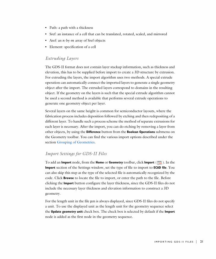
• Path: a path with a thickness
• Sref: an instance of a cell that can be translated, rotated, scaled, and mirrored
• Aref: an n-by-m array of Sref objects
• Element: specification of a cell
Extruding Layers
The GDS-II format does not contain layer stackup information, such as thickness and elevation, this has to be supplied before import to create a 3D structure by extrusion. For extruding the layers, the import algorithm uses two methods. A special extrude operation can automatically connect the imported layers to generate a single geometry object after the import. The extruded layers correspond to domains in the resulting object. If the geometry on the layers is such that the special extrude algorithm cannot be used a second method is available that performs several extrude operations to generate one geometry object per layer.
Several layers on the same height is common for semiconductor layouts, where the fabrication process includes deposition followed by etching and then redepositing of a different layer. To handle such a process scheme the method of separate extrusions for each layer is necessary. After the import, you can do etching by removing a layer from other objects, by using the Difference button from the Boolean Operations submenu on the Geometry toolbar. You can find the various import options described under the section Grouping of Geometries.
Import Settings for GDS-II Files
To add an Import node, from the Home or Geometry toolbar, click Import ( ). In the Import section of the Settings window, set the type of file to import to ECAD file. You can also skip this step as the type of the selected file is automatically recognized by the code. Click Browse to locate the file to import, or enter the path to the file. Before clicking the Import button configure the layer thickness, since the GDS-II files do not include the necessary layer thickness and elevation information to construct a 3D geometry.
For the length unit in the file μm is always displayed, since GDS-II files do not specify a unit. To use the displayed unit as the length unit for the geometry sequence select the Update geometry unit check box. The check box is selected by default if the Import node is added as the first node in the geometry sequence.
I M P O R T I N G G D S - I I F I L E S | 21

22 | C H A P T E R
C E L L S E L E C T I O N
Data contained in GDS-II files is organized in hierarchical structure consisting of cells. Select a cell name from the Cell to import list to limit the import to the selected cell beneath the top cell in the hierarchy. Use the default choice in this list to import the top cell. By default all sub-cells below the selected cell are imported. To import only one sub-cell type, select the cell from the Filter by subcell list. The difference between selecting a cell and filtering the top cell by the same cell is that the latter alternative includes all instances of the selected cell, whereas the first case only includes the selected instance of the cell.
G R O U P I N G O F G E O M E T R I E S
The import operation can construct a single 3D geometric object with separate domains for the layers and the various objects on the layers. You also have the option to import each layer into its own geometric object, or to import each object from the layers in the file into its own geometric object. To determine which method to use select one of the available alternatives from the Grouping of geometries list:
• All. This alternative is available only in 3D. Use it to group all imported layers and the object contained on those into a single geometric object. To construct the 3D geometric object the import algorithm extrudes and combines all layers directly. The imported objects, and layers become domains in the resulting geometric object.
• By layer. Use this alternative to combine the imported objects from each layer into a single geometric object. Several geometric objects, one for each imported layer, are output by the import.
• No grouping. Use this alternative to import each object from the layers into individual geometric objects. To construct the geometric objects the import performs a union of all the segments.
With the Type of import setting the extrusion of layers can be switched on or off. The Full 3D option imports all layers with a thickness, as specified in the Layers to import table. With the Metal shell option layers are imported as embedded surfaces in one surface object (with grouping All), one surface object per layer (with grouping By
layer), or one surface object per imported object (with grouping No grouping).
C O N T R O L L I N G T H E L A Y E R S T A C K U P
Since layer stackup information is not included in GDS-II files, the layers are assigned a default zero thickness in the Layers to import table. These values can be edited before importing the GDS-II file.
2 : I M P O R T I N G E C A D F I L E S
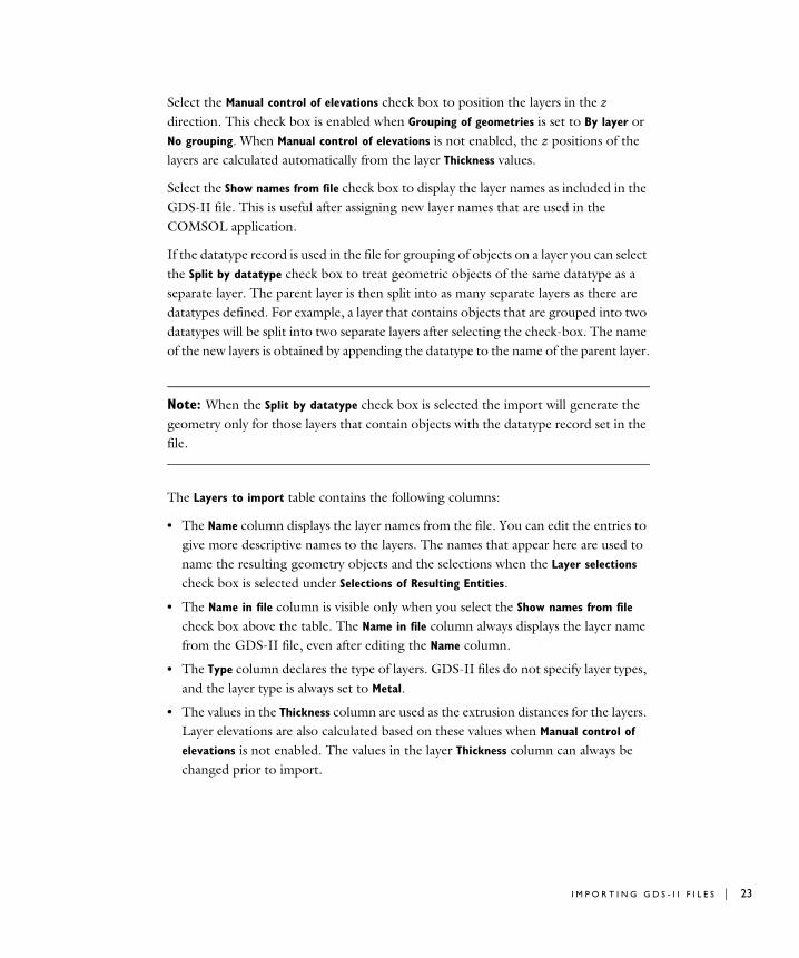
Select the Manual control of elevations check box to position the layers in the z direction. This check box is enabled when Grouping of geometries is set to By layer or No grouping. When Manual control of elevations is not enabled, the z positions of the layers are calculated automatically from the layer Thickness values.
Select the Show names from file check box to display the layer names as included in the GDS-II file. This is useful after assigning new layer names that are used in the COMSOL application.
If the datatype record is used in the file for grouping of objects on a layer you can select the Split by datatype check box to treat geometric objects of the same datatype as a separate layer. The parent layer is then split into as many separate layers as there are datatypes defined. For example, a layer that contains objects that are grouped into two datatypes will be split into two separate layers after selecting the check-box. The name of the new layers is obtained by appending the datatype to the name of the parent layer.
Note: When the Split by datatype check box is selected the import will generate the geometry only for those layers that contain objects with the datatype record set in the file.
The Layers to import table contains the following columns:
• The Name column displays the layer names from the file. You can edit the entries to give more descriptive names to the layers. The names that appear here are used to name the resulting geometry objects and the selections when the Layer selections check box is selected under Selections of Resulting Entities.
• The Name in file column is visible only when you select the Show names from file check box above the table. The Name in file column always displays the layer name from the GDS-II file, even after editing the Name column.
• The Type column declares the type of layers. GDS-II files do not specify layer types, and the layer type is always set to Metal.
• The values in the Thickness column are used as the extrusion distances for the layers. Layer elevations are also calculated based on these values when Manual control of
elevations is not enabled. The values in the layer Thickness column can always be changed prior to import.
I M P O R T I N G G D S - I I F I L E S | 23

24 | C H A P T E R
• The values in the Elevation column control the lower z positions of the layers. By adjusting the values you can adjust the position of layers in the stackup. The Elevation column is only displayed when Manual control of elevations is enabled.
• The Import column. Clear the check box for layers that do not need to be imported.
To save the layers table to a text file, click the Save to File button ( ) under the table. To load layer table information from a text file, click the Load from File button ( ) under the table. Only the editable data in the table is affected when loading from file. Layer data in the file that does not match the existing layers in the table is ignored.
I N T E R I O R B O U N D A R I E S
By default the Keep interior boundaries check box is cleared to instruct the import to remove all interior boundaries on the imported layers. This keeps the geometry complexity to a minimum and can also make the import more robust in some situations.
A R C R E C O G N I T I O N
Recognition of arcs and straight lines can significantly reduce the complexity of imported layouts from GDS files. With the Recognize arcs set to Automatic, all polygon chains that represent arcs are identified and replaced with more efficient curve objects, and polygon segments that lie on a single straight line are recognized and joined into a single straight segment.
With Recognize arcs set to Manual, the following settings will help you fine tune the process of the merging of segments into a single circular arc:
• Minimum angle between segments: this parameter prohibits merging of two adjacent polygon segments to a circular arc if the angle between them is less than the provided number.
• Maximum angle between segments: this prohibits merging of two adjacent polygon segments to a circular arc if the angle between them is greater than the provided number.
• Maximum curvature deviation: this prohibits merging a polygon segment to the constructed circular arc if that would (relatively) change the curvature by more than the provided number.
2 : I M P O R T I N G E C A D F I L E S

• Maximum length deviation: this prohibits merging of two adjacent polygon segments to a circular arc if the relative difference between the lengths is greater than the provided number.
• Maximum deviation from circle: the allowed maximum relative error between the polygon segments and the constructed circular arc.
In manual arc recognition mode, the Find straight lines check box controls whether to convert several polygon segments that lie on a straight line into a single straight segment. This option uses the number in the Minimum angle between segments field to determine if a group of segments lie on the same straight line.
R E P A I R
Geometry repair is controlled via the Repair imported data check box and the Repair
tolerance list. Change the Repair tolerance from Automatic to Relative to manually specify a tolerance in the Relative repair tolerance edit field. The geometry repair allows to repair incorrectly drawn objects, such as polygons with (small) gaps.
If selected, the geometry repair is also active when combining the imported objects in a cell or layer. By increasing the repair tolerance, problems with short edges arising when combining the objects can sometimes be circumvented.
S E L E C T I O N S O F R E S U L T I N G E N T I T I E S
If you want to make the resulting entities contribute to a cumulative selection, select a cumulative selection from the Contribute to list (the default, None, gives no contribution), or click the New button to create a new cumulative selection (see Cumulative Selections in the COMSOL Multiphysics Reference Manual).
Select the Resulting objects selection check box to create predefined selections (for all levels — objects, domains, boundaries, edges, and points — that are applicable) in subsequent nodes in the geometry sequence. To also make all or one of the types of resulting entities (domains, boundaries, edges, and points) that the resulting objects consist of available as selections in all applicable selection lists (in physics and materials settings, for example), choose an option from the Show in physics list: All levels, Domain
selection, Boundary selection, Edge selection, or Point selection. The default is Domain
selection, which is suitable for use with materials and physics defined in domains. For use with a boundary condition, for example, choose Boundary selection. These selections do not appear as separate selection nodes in the model tree. Select Off to not make any selection available outside of the geometry sequence.
I M P O R T I N G G D S - I I F I L E S | 25
26 | C H A P T E R
Select the Layer selections check box to create predefined selections — for domains, boundaries, and objects — in subsequent nodes in the geometry sequence for each imported layer in the GDS file. To also make all of one of the resulting entities that the layers consist of available as selections in all applicable selection lists (in physics and materials settings, for example), choose an option from the Show in physics list: All
levels, Domain selection, or Boundary selection. The default is All levels, which makes predefined selections available on all applicable levels, suitable for use with materials and physics defined in domains and boundaries. For use with a boundary condition, for example, choose Boundary selection. These selections do not appear as separate selection nodes in the model tree. Select Off to not make any selection available outside of the geometry sequence.
Select the Cell selections check box to create predefined selections — for domains and boundaries — in subsequent nodes in the geometry sequence for each imported cell in the GDS file. To also make all of one of the resulting entities that the cells consist of available as selections in all applicable selection lists (in physics and materials settings, for example), choose an option from the Show in physics list: All levels, Domain
selection, or Boundary selection. The default is Domain selection, if available, which is suitable for use with materials and physics defined in domains. For use with a boundary condition, for example, choose Boundary selection. These selections do not appear as separate selection nodes in the model tree. Select Off to not make any selection available outside of the geometry sequence.
2 : I M P O R T I N G E C A D F I L E S
Impo r t i n g NETEX -G F i l e s
In this section:
• The NETEX-G File Format
• Creating NETEX-G Files for Import into COMSOL
• Extruding Layers
• Import Settings for NETEX-G Files
The NETEX-G File Format
The NETEX-G file format is a special format produced by the application NETEX-G by Artwork (www.artwork.com). NETEX-G can read and process Gerber and drill files that are widely used when sending PCB layouts to manufacturing. The output file is an ASCII file with a GDS-II like structure, containing information about the layout of each layer, the layer thickness, vias, and dielectric layers. The geometric objects are defined and instantiated in the same way as in a GDS-II file; see The GDS-II File Format for a description of that format.
F I L E E X T E N S I O N
The file extension of the NETEX-G format is not set, but the ECAD import requires it to be .asc, otherwise it cannot identify the file as a NETEX-G file. If the file has a different extension, change the name before importing it.
B O N D W I R E S
A NETEX-G file can contain information about bond wires according to the JEDEC standard. It is possible to define the bond wire as a JEDEC3 or a JEDEC4 model. These models define the bond wire as 3- or 4-segment paths with user-supplied coordinates and elevations. In a NETEX-G file the bond wires connect layers to a special die layer, representing the semiconductor die. Bond wires can be imported using three different complexity levels, see Importing Bond Wires.
Creating NETEX-G Files for Import into COMSOL
This is a brief description of the main steps to produce a NETEX-G file for import into COMSOL Multiphysics. For specific details, see the NETEX-G documentation.
I M P O R T I N G N E T E X - G F I L E S | 27

28 | C H A P T E R
G E R B E R L A Y E R F I L E S
The first type of input files to NETEX-G is a collection of Gerber files, one for each layer. The ECAD software generates these files when the PCB layout is sent to manufacturing. The layer files do not contain any information about layer thickness, layer materials, dielectrics, and electrical connectivity (nets). Furthermore, a standard PCB layout usually consists of a large number of conductors, vias, and symbols printed in metal that are not important for a finite element simulation. With NETEX-G the size of the exported layout can be reduced in the following ways:
• Defining a region to include in the export. This region is drawn directly on a top view of the layout.
• Exclude entire layers from the layout.
• Selecting electrical nets to include in the export in addition to the selected region.
• It is also possible to let NETEX-G include nets in the proximity of the selected nets.
Because the Gerber layer files do not contain any physical information about the layer and dielectrics, this information must be specified in NETEX-G.
Some of these steps can also be done during import to COMSOL Multiphysics, for example, excluding layers from the import and changing the thickness and elevation of the layers.
D R I L L F I L E S
The connectivity between the layers is defined through drilled holes, known as vias. A via can go through the entire circuit board or just between certain layers. Most ECAD programs use the Excellon drill file format to specify the vias, which contains information about via diameter and position. Before generating the final output file from NETEX-G, it is necessary to convert all drill files to Gerber format and include them to the export project in NETEX-G. For each drill file, it is also necessary to specify between which layers the hole goes. Within NETEX-G a tool can be called that directly converts the Excellon drill format into Gerber. After the conversion, also specify the source and destination layers for the drill file.
N E T E X - G E X P O R T S E T T I N G S
To reduce the complexity of the output file it is recommended that vias are exported as circles and not as polygons. Although the arc recognition utility can detect these polygons, the former option is more robust.
2 : I M P O R T I N G E C A D F I L E S

Extruding Layers
To obtain a 3D geometry for the board the 2D layouts from the NETEX-G file are extruded, according to the layer stackup information, using one of two methods. A special extrude operation can automatically connect the imported layers to generate a single geometry object after the import. The extruded layers correspond to domains in the resulting object. If the 2D layouts are such that the special extrude algorithm cannot be used a second method is available that performs several extrude operations to generate one geometry object per layer. See how to select the import method in Grouping of Geometries.
Import Settings for NETEX-G Files
To add an Import node, from the Home or Geometry toolbar, click Import ( ). In the Import section of the Settings window, set the type of CAD file to import to ECAD file. You can also skip this step as the type of the selected file is automatically recognized by the code. Click Browse to locate the file to import, or enter the path to the file. Before clicking the Import button consider to review and configure the import settings.
The length unit in the file is detected and displayed in the Settings window. To use the unit in the file as the length unit for the geometry sequence select the Update geometry
unit check box. The check box is selected by default if the Import node is added as the first node in the geometry sequence.
N E T S E L E C T I O N
In a manner similar to cells in GDS-II files, data contained in NETEX-G files is organized in hierarchical structure consisting of electrical nets. Select a net name from the Net to import to limit the import to the selected electrical net beneath the top net in the hierarchy. Use the default choice in this list to import the top net. By default all sub-nets below the selected net are imported. To import only one sub-net type, select the net from the Filter by subnet list. The difference between selecting a net and filtering the top net by the same net is that the latter alternative includes all instances of the selected net, whereas the first case only includes the selected instance of the net.
I M P O R T I N G N E T E X - G F I L E S | 29

30 | C H A P T E R
G R O U P I N G O F G E O M E T R I E S
To determine the extrusion method used for generating the 3D geometry from the 2D layouts in the file select one of the available alternatives from the Grouping of geometries list:
• All. This alternative is available only in 3D. The import algorithm extrudes in one operation all imported copper and dielectric layers into a single 3D geometric object. From each copper layer, the imported nets are combined before extrusion. The copper and dielectric layers become domains in the resulting object. To be able to connect the layers, the algorithm requires that the 2D layouts fulfill certain rules. If the import fails, switch to the By layer grouping option.
• By layer. Use this alternative to extrude each layer separately. The imported nets from the copper layers are combined before extrusion. Several geometric objects, one for each imported copper and dielectric layer, are output by the import.
• No grouping. Use this alternative to import and extrude individually each geometric shape that makes up the electrical nets from the copper layers. The import results in separate objects for the imported shapes, nets and layers.
C O P P E R L A Y E R S
The Type of import list specifies how to treat metal (copper) layers. The Full 3D option imports all copper layers with a thickness according to the Layers to import table. With the Metal shell options copper layers are imported as embedded boundaries between dielectric regions. As illustrated in the figure below, this setting does not affect the
2 : I M P O R T I N G E C A D F I L E S
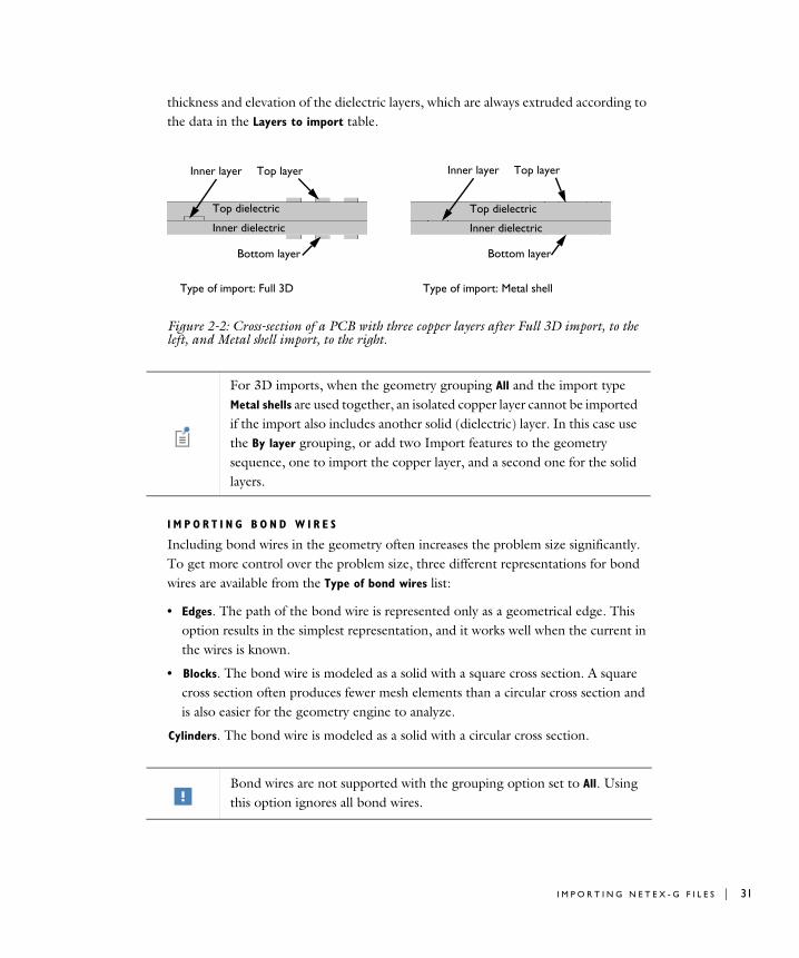
thickness and elevation of the dielectric layers, which are always extruded according to the data in the Layers to import table.
Figure 2-2: Cross-section of a PCB with three copper layers after Full 3D import, to the left, and Metal shell import, to the right.
I M P O R T I N G B O N D W I R E S
Including bond wires in the geometry often increases the problem size significantly. To get more control over the problem size, three different representations for bond wires are available from the Type of bond wires list:
• Edges. The path of the bond wire is represented only as a geometrical edge. This option results in the simplest representation, and it works well when the current in the wires is known.
• Blocks. The bond wire is modeled as a solid with a square cross section. A square cross section often produces fewer mesh elements than a circular cross section and is also easier for the geometry engine to analyze.
Cylinders. The bond wire is modeled as a solid with a circular cross section.
Inner layer
Top dielectric
Top layer
Inner dielectric
Bottom layer
Inner layer
Top dielectric
Top layer
Inner dielectric
Bottom layer
Type of import: Full 3D Type of import: Metal shell
For 3D imports, when the geometry grouping All and the import type Metal shells are used together, an isolated copper layer cannot be imported if the import also includes another solid (dielectric) layer. In this case use the By layer grouping, or add two Import features to the geometry sequence, one to import the copper layer, and a second one for the solid layers.
Bond wires are not supported with the grouping option set to All. Using this option ignores all bond wires.
I M P O R T I N G N E T E X - G F I L E S | 31
32 | C H A P T E R
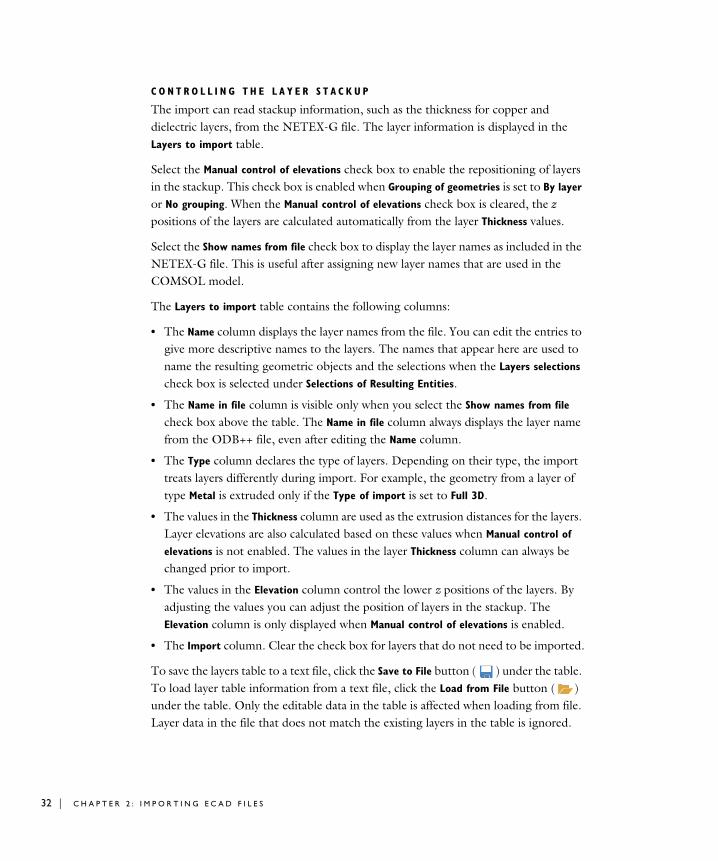
C O N T R O L L I N G T H E L A Y E R S T A C K U P
The import can read stackup information, such as the thickness for copper and dielectric layers, from the NETEX-G file. The layer information is displayed in the Layers to import table.
Select the Manual control of elevations check box to enable the repositioning of layers in the stackup. This check box is enabled when Grouping of geometries is set to By layer or No grouping. When the Manual control of elevations check box is cleared, the z positions of the layers are calculated automatically from the layer Thickness values.
Select the Show names from file check box to display the layer names as included in the NETEX-G file. This is useful after assigning new layer names that are used in the COMSOL model.
The Layers to import table contains the following columns:
• The Name column displays the layer names from the file. You can edit the entries to give more descriptive names to the layers. The names that appear here are used to name the resulting geometric objects and the selections when the Layers selections check box is selected under Selections of Resulting Entities.
• The Name in file column is visible only when you select the Show names from file check box above the table. The Name in file column always displays the layer name from the ODB++ file, even after editing the Name column.
• The Type column declares the type of layers. Depending on their type, the import treats layers differently during import. For example, the geometry from a layer of type Metal is extruded only if the Type of import is set to Full 3D.
• The values in the Thickness column are used as the extrusion distances for the layers. Layer elevations are also calculated based on these values when Manual control of
elevations is not enabled. The values in the layer Thickness column can always be changed prior to import.
• The values in the Elevation column control the lower z positions of the layers. By adjusting the values you can adjust the position of layers in the stackup. The Elevation column is only displayed when Manual control of elevations is enabled.
• The Import column. Clear the check box for layers that do not need to be imported.
To save the layers table to a text file, click the Save to File button ( ) under the table. To load layer table information from a text file, click the Load from File button ( ) under the table. Only the editable data in the table is affected when loading from file. Layer data in the file that does not match the existing layers in the table is ignored.
2 : I M P O R T I N G E C A D F I L E S

D I E L E C T R I C R E G I O N S
The Import dielectric regions check box controls if the import engine also includes the dielectric layers. It is possible to define the PCB outline using left, right, top, and bottom margins for the dielectric material. They define the distance between the exterior of the PCB and the bounding box of all metal layers. The Import dielectric
regions check box is disabled when Manual control of elevations is enabled.
I N T E R I O R B O U N D A R I E S
By default the Keep interior boundaries check box is cleared to instruct the import to remove all interior boundaries on the imported layers. This keeps the geometry complexity to a minimum and can also make the import more robust in some situations.
A R C R E C O G N I T I O N
Recognition of arcs and straight lines can significantly reduce the complexity of imported layouts from NETEX-G files. With the Recognize arcs set to Automatic, all polygon chains that represent arcs are identified and replaced with more efficient curve objects. With the fields appearing when setting this to Manual, the arc recognition can be fine tuned. In manual mode, the Find straight lines check box controls whether to convert several polygon segments that lie on a single straight line into a single straight segment. This option uses the number in the Minimum angle between segments field to determine if a group of segments lies on the same straight line.
R E P A I R
Geometry repair is controlled via the Repair imported data check box and the Repair
tolerance list. Change the Repair tolerance from Automatic to Relative to manually specify a tolerance in the Relative repair tolerance edit field. The geometry repair allows to repair incorrectly drawn objects, such as polygons with (small) gaps.
If selected, the geometry repair is also active when combining the imported objects in a net or layer. By increasing the repair tolerance, problems with short edges arising when combining the objects can sometimes be circumvented.
S E L E C T I O N S O F R E S U L T I N G E N T I T I E S
If you want to make the resulting entities contribute to a cumulative selection, select a cumulative selection from the Contribute to list (the default, None, gives no contribution), or click the New button to create a new cumulative selection (see Cumulative Selections in the COMSOL Multiphysics Reference Manual).
I M P O R T I N G N E T E X - G F I L E S | 33

34 | C H A P T E R
Select the Resulting objects selection check box to create predefined selections (for all levels — objects, domains, boundaries, edges, and points — that are applicable) in subsequent nodes in the geometry sequence. To also make all or one of the types of resulting entities (domains, boundaries, edges, and points) that the resulting objects consist of available as selections in all applicable selection lists (in physics and materials settings, for example), choose an option from the Show in physics list: All levels, Domain
selection, Boundary selection, Edge selection, or Point selection. The default is Domain
selection, which is suitable for use with materials and physics defined in domains. For use with a boundary condition, for example, choose Boundary selection. These selections do not appear as separate selection nodes in the model tree. Select Off to not make any selection available outside of the geometry sequence.
Select the Layer selections check box to create predefined selections — for domains, boundaries, and objects — in subsequent nodes in the geometry sequence for each imported layer in the NETEX-G file. To also make all of one of the resulting entities that the layers consist of available as selections in all applicable selection lists (in physics and materials settings, for example), choose an option from the Show in physics list: All
levels, Domain selection, or Boundary selection. The default is All levels, which makes predefined selections available on all applicable levels, suitable for use with materials and physics defined in domains and boundaries. For use with a boundary condition, for example, choose Boundary selection. These selections do not appear as separate selection nodes in the model tree. Select Off to not make any selection available outside of the geometry sequence.
Select the Net selections check box to create predefined selections — for domains and boundaries — in subsequent nodes in the geometry sequence for each imported net in the NETEX-G file. To also make all of one of the resulting entities that the nets consist of available as selections in all applicable selection lists (in physics and materials settings, for example), choose an option from the Show in physics list: All levels, Domain
selection, or Boundary selection. The default is Domain selection, if available, which is suitable for use with materials and physics defined in domains. For use with a boundary condition, for example, choose Boundary selection. These selections do not appear as separate selection nodes in the model tree. Select Off to not make any selection available outside of the geometry sequence.
2 : I M P O R T I N G E C A D F I L E S

Me sh i n g an Impo r t e d Geome t r y
The imported geometry often consists of objects with very high aspect ratios, which are hard to mesh with a free tetrahedron mesh generator. As a result, it is often necessary to use interactive meshing of the imported geometry in a by-layer fashion.
The following section describes this procedure in general terms.
This procedure assumes that the top and bottom layers are metal layers. All metal layers can often be meshed using swept meshing, but dielectric layers usually cannot be meshed that way. Begin by meshing from the bottom or top layer, starting with a boundary mesh. Then mesh layer by layer, where each metal layer gets a swept mesh, and each dielectric layer (with vias) gets a free mesh.
The dielectric layers cannot use a swept mesh because the source and target boundaries usually do not look the same. If there is a surrounding air domain it is usually not possible to use swept meshes for the metal layers either. Use tetrahedra or convert the swept mesh to tetrahedra before meshing the surrounding domain.
Meshing and Convert in the COMSOL Multiphysics Reference Manual.
M E S H I N G A N I M P O R T E D G E O M E T R Y | 35

36 | C H A P T E R
T r oub l e s h oo t i n g ECAD Impo r t
In this section:
• Tuning Import Settings
• Problems when Extruding Layers
• Problems with Several Geometry Objects
Tuning Import Settings
D E L E T E I N T E R I O R E D G E S
A complex layout produces a large number of faces that can be hard to render. A simple way to reduce the number of faces is to clear the Keep interior boundaries check box in the ECAD import options. This removes all faces internal to the nets within a layer.
R E M O V I N G F E A T U R E S
Remove all features that are not important for the simulation. This is usually best to do before the import in NETEX-G or in the ECAD software. When importing with Grouping of geometries set to No grouping it is possible to manually delete certain objects after import, but it is recommended to do this only for relatively simple geometries.
Problems when Extruding Layers
Most ECAD or EDA programs support design rule checks (DRC), which test the entire layout and check that all features (vias, conductors, and components) are separated according to certain rules. With such checks the layout is free from overlapping vias and conductors touching other conductors or vias. This also ensures that the special extrude functionality of the ECAD import works properly. If the file contains such design-rule violations, the extrude might fail and throw an error message stating that it could not handle the topology of the layout.
The best approach to handle such problems is to perform a DRC with your ECAD software and produce new layout files. If this is not possible, import the layout in 2D and try to identify the problematic features. They can either be in a single layer or at the interface between two adjacent layers. When identified, it is possible to remove them manually using a text editor if a NETEX-G or ODB++(X) file is being imported. It can be hard to find a certain feature, but use either the coordinate or the net
2 : I M P O R T I N G E C A D F I L E S

information to find it. The GDS format is a binary file format so it is very difficult to edit the file manually.
Problems with Several Geometry Objects
If the special extrude functionality is not used, you get several geometry objects, for example, one for each layer if By layer is selected from the Grouping of geometries list. After a CAD import COMSOL Multiphysics is in the Geometry branch of the model tree. When you continue to the Materials branch if the model tree or to a physics interface node or the Mesh branch, the program tries to combine all the objects into one geometry, and this operation might fail if the objects are very complex and have high aspect rations. Resolve this either by trying the option All in the Grouping of
geometries list. This creates one combined geometry object by using the special extrude functionality, and with only one object this.
Another possibility is to use assemblies, because then COMSOL Multiphysics does not have to combine the objects (parts). This is controlled by the Form Union/Assembly node in the Geometry branch of the model tree. When using an assembly, use identity pairs to connect the interfaces between the layers.
As a final option, do not import the dielectric layers. The import then leaves isolated metal layers that have to connect with coupling variables.
T R O U B L E S H O O T I N G E C A D I M P O R T | 37

38 | C H A P T E R
2 : I M P O R T I N G E C A D F I L E S
3
P r o g r a m m i n g a n d C o m m a n d R e f e r e n c e
In this section you find detailed COMSOL API reference information for the geometry features in the ECAD Import Module.
In this section:
• Commands Grouped by Function
39
40 | C H A P T E R
Command s G r oup ed b y Fun c t i o n
Commands for File Import
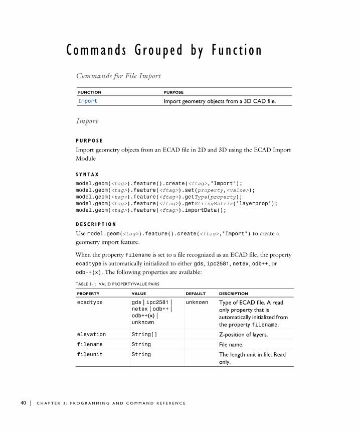
Import
P U R P O S E
Import geometry objects from an ECAD file in 2D and 3D using the ECAD Import Module
S Y N T A X
model.geom(<tag>).feature().create(<ftag>,"Import");model.geom(<tag>).feature(<ftag>).set(property,<value>);model.geom(<tag>).feature(<ftag>).getType(property);model.geom(<tag>).feature(<ftag>).getStringMatrix("layerprop");model.geom(<tag>).feature(<ftag>).importData();
D E S C R I P T I O N
Use model.geom(<tag>).feature().create(<ftag>,"Import") to create a geometry import feature.
When the property filename is set to a file recognized as an ECAD file, the property ecadtype is automatically initialized to either gds, ipc2581, netex, odb++, or odb++(x). The following properties are available:
FUNCTION PURPOSE
Import Import geometry objects from a 3D CAD file.
TABLE 3-1: VALID PROPERTY/VALUE PAIRS
PROPERTY VALUE DEFAULT DESCRIPTION
ecadtype gds | ipc2581 | netex | odb++ | odb++(x) | unknown
unknown Type of ECAD file. A read only property that is automatically initialized from the property filename.
elevation String[] Z-position of layers.
filename String File name.
fileunit String The length unit in file. Read only.
3 : P R O G R A M M I N G A N D C O M M A N D R E F E R E N C E

grouping all | layer | none layer The grouping of the imported layers, where all returns one single object, and layers gives you one object per layer. In 2D, all is the same as layer.
height String[] Thickness of layers.
importlayer String[] The entries in the array govern if the corresponding layer is to be imported. Each entry value is either "on" or "off".
importtype full3d | shell full3d Determine if metal layers are imported as solid or faces in 3D.
intbnd on | off on Keep interior boundaries on layers.
layername String[] The user names for the layers. Empty string implies the name is taken from the ECAD file.
manualelevation on | off off Manual control of elevations.
repairgeom on | off on Repair imported objects.
repairtol double 1e-5 (for GDS and Netex-G)
1e-6 (for ODB++ and IPC-2581
Repair tolerance, relative to size of union of imported objects. Setting this property will automatically set repairtoltype to relative and repairgeom to on.
repairtoltype auto | relative auto Determine if repair tolerance is set automatically or manually by the repairtol property.
selresult on | off off Create selections of all resulting objects.
TABLE 3-1: VALID PROPERTY/VALUE PAIRS
PROPERTY VALUE DEFAULT DESCRIPTION
C O M M A N D S G R O U P E D B Y F U N C T I O N | 41

42 | C H A P T E R
The file specified by filename can be of any of the following formats:
The imported objects are represented using COMSOL’s geometry modeler.
selresultshow all | obj | dom | bnd | edg | pnt | off
The highest available entity level except obj; usually dom.
Show selections of resulting objects in physics, materials, and so on, or in part instances. obj is not available in a component’s geometry. dom, bnd, and edg are not available in all features.
sellayer on | off on Create layer selections.
sellayershow all | dom | bnd | off
all Show layer selections in physics, materials, and so on, and in part instances (when sellayer is on). This property is not available in a work plane’s Plane Geometry.
updategeomunit Boolean true or false
The default is true if the feature is the first in the geometry sequence, else false. If true the geometry sequence unit will be updated to the fileunit value when performing the import.
contributeto String none Tag of cumulative selection to contribute to.
createselection on | off off Create selections.
TABLE 3-2: SUPPORTED FILE FORMATS
FILE FORMAT FILE EXTENSIONS ECADTYPE
GDS .gds gds
IPC-2581 .cvg,.xml ipc2581
NETEX-G .asc netex
ODB++® .zip, .tar, .tgz, .tar.tgz
odb++
ODB++(X) .xml odb++(x)
TABLE 3-1: VALID PROPERTY/VALUE PAIRS
PROPERTY VALUE DEFAULT DESCRIPTION
3 : P R O G R A M M I N G A N D C O M M A N D R E F E R E N C E

The property ecadtype determines which properties are available, see Table 3-2 for supported types. The property ecadtype is read only, and it is automatically initialized from the property filename, according to Table 3-2.
The property importlayer determines which layers to import. It is a string array of the same length as the number of layers, holding the strings on or off. The property is initialized with a valid default when setting the property filename.
To inspect available layers in a file, use the method
model.geom(<tag>).feature(<ftag>).getStringMatrix("layerprop");
It returns a String[][], with the same number of rows as the number of layers, that contains information about each layer.
The property height determines the height of all layers. It is a string array of the same length as the number of layers, holding string representations of the layer height, for example 1[mm]. The property is initialized with a valid default when setting the property filename.
The property manualelevation controls how imported layers are positioned in the Z direction. When manualelevation is off, the imported layers are stacked on top of each other with no gaps, so the Z positions are computed from the height property. When manualelevation is on and grouping is set to layer or none, the imported layers are positioned in the Z direction as specified by the elevation property. To switch to manual control of elevations it is recommended to first set manualelevation to on, then set the values for the height and elevation properties.
The property elevation determines the Z-position of all layers. It is a string array of the same length as the number of layers, holding string representations of the layer elevation. The property is initialized with a valid default on these occasions:
• when setting the property filename,
• when setting the property manualelevation to off,
• when manualelevation is off, and the value of the height property is changed,
• when manualelevation is off, and the value of the importtype property is changed.
If selresult is set to on, a selection is created for all resulting entities of each type (object, domain, boundary, edge, and point), for use in the geometry sequence. To access the object selection, use model.geom(<tag>).selection(<ftag>), where <tag> is the geometry tag and <ftag> is the feature tag. To access the other selections,
C O M M A N D S G R O U P E D B Y F U N C T I O N | 43

44 | C H A P T E R
use model.geom(<tag>).selection(<ftag>.<lvl>), where <tag> is the geometry tag, <ftag> is the feature tag, and <lvl> is one of dom, bnd, edg, or pnt. If, in addition, selresultshow is set to a value other than off, all or some of these selections appear for use outside the geometry sequence. To access these selections, use model.selection(<tag>_<ftag>_<lvl>), where <tag> is the geometry tag, <ftag> is the feature tag, and <lvl> is one of dom, bnd, edg, or pnt.
If sellayer is set to on, a selection is created for all resulting entities of the types object, domain, and boundary, of each layer, for use in the geometry sequence. To access the object selections, use model.geom(<tag>).selection(<ftag>_<otag>), where <otag> is a tag derived from the name of the imported layer. <otag> is derived by replacing space and dot characters with underscore characters and removing other characters that are not numbers or uppercase or lowercase English characters (A–Z and a–z). Additionally, if required to make <otag> unique, _<m> is appended, where <m> is an integer. To access the other selections, use model.geom(<tag>).selection(<ftag>_<otag>.dom) or model.geom(<tag>).selection(<ftag>_<otag>.bnd), where <otag> is a tag derived from the name of the imported layer. If, in addition, sellayershow is set to a value other than off, all or some of these selections appear for use outside the geometry sequence.
To access these selections, use model.selection(<tag>_<ftag>_<otag>_dom) or model.selection(<tag>_<ftag>_<otag>_bnd), where <otag> is a tag derived from the name of the imported layer.
If the file type is GDS, you can create additional selections for each imported cell by using the properties selcell and selcellshow.
If the file type is NETEX-G, you can create additional selections for each imported net by using the properties selnet and selnetshow.
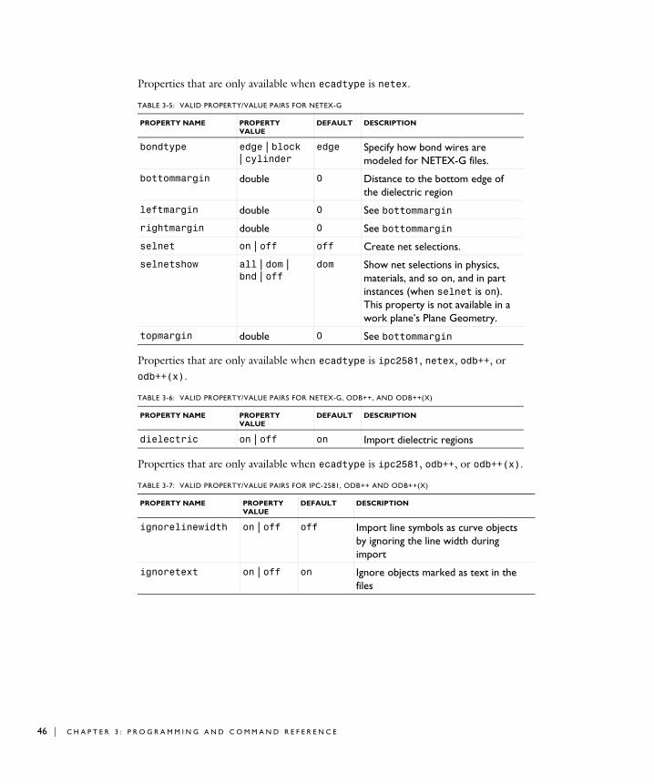
Properties that are only available when ecadtype is gds or netex.
TABLE 3-3: VALID PROPERTY/VALUE PAIRS FOR GDS AND NETEX-G
PROPERTY NAME PROPERTY VALUE
DEFAULT DESCRIPTION
arcdistancetol double 0.3 Tolerance for segment length deviation.
arcmaxangle double 36 Maximum angle for segments.
arcminangle double 3.6 Minimum angle for segments to part of an arc.
3 : P R O G R A M M I N G A N D C O M M A N D R E F E R E N C E

When findarcs is auto or manual, line segments are combined to form arcs. If findarcs is manual, the properties arcdistancetol, arcradiustol, arcminangle, arcmaxangle, and findlines can be used to tune the arc recognition algorithm, otherwise the algorithm tries to determine optimal parameters
Properties that are only available when ecadtype is gds.
arcmaxcircledev double 1e-3 Maximum allowed point deviation from a circle, relative to the circle radius.
arcradiustol double 0.4 Tolerance for arc curvature.
cell String top net Name of top net or cell to import.
cellfilter String all Name of net or cell to include. Leave empty to include all nets or cells below the top net.
findarcs auto | manual | off
auto Control arc recognition.
findlines on | off on Turn on straight line recognition. Only available when findarcs is manual.
TABLE 3-4: VALID PROPERTY/VALUE PAIRS FOR GDS
PROPERTY NAME PROPERTY VALUE
DEFAULT DESCRIPTION
selcell on | off off Create cell selections.
selcellshow all | dom | bnd | off
dom Show cell selections in physics, materials, and so on, and in part instances (when selcell is on). This property is not available in a work plane’s Plane Geometry.
splitbydatatype on | off off Treat datatypes as separate layers
TABLE 3-3: VALID PROPERTY/VALUE PAIRS FOR GDS AND NETEX-G
PROPERTY NAME PROPERTY VALUE
DEFAULT DESCRIPTION
C O M M A N D S G R O U P E D B Y F U N C T I O N | 45
46 | C H A P T E R
Properties that are only available when ecadtype is netex.
Properties that are only available when ecadtype is ipc2581, netex, odb++, or odb++(x).
Properties that are only available when ecadtype is ipc2581, odb++, or odb++(x).
TABLE 3-5: VALID PROPERTY/VALUE PAIRS FOR NETEX-G
PROPERTY NAME PROPERTY VALUE
DEFAULT DESCRIPTION
bondtype edge | block | cylinder
edge Specify how bond wires are modeled for NETEX-G files.
bottommargin double 0 Distance to the bottom edge of the dielectric region
leftmargin double 0 See bottommargin
rightmargin double 0 See bottommargin
selnet on | off off Create net selections.
selnetshow all | dom | bnd | off
dom Show net selections in physics, materials, and so on, and in part instances (when selnet is on). This property is not available in a work plane’s Plane Geometry.
topmargin double 0 See bottommargin
TABLE 3-6: VALID PROPERTY/VALUE PAIRS FOR NETEX-G, ODB++, AND ODB++(X)
PROPERTY NAME PROPERTY VALUE
DEFAULT DESCRIPTION
dielectric on | off on Import dielectric regions
TABLE 3-7: VALID PROPERTY/VALUE PAIRS FOR IPC-2581, ODB++ AND ODB++(X)
PROPERTY NAME PROPERTY VALUE
DEFAULT DESCRIPTION
ignorelinewidth on | off off Import line symbols as curve objects by ignoring the line width during import
ignoretext on | off on Ignore objects marked as text in the files
3 : P R O G R A M M I N G A N D C O M M A N D R E F E R E N C E

Properties that are only available when ecadtype is ipc2581 or odb++.
You can use the net selection tag as a key when setting array elements in the other properties by using set(property,<ntag>, value), where <ntag> is a tag derived from the name of the net selection.
To access net selections, use model.selection(<tag>_<ftag>_<ntag>_dom) or model.selection(<tag>_<ftag>_<ntag>_bnd), where <ntag> is the tag of the net selection.
TABLE 3-8: VALID PROPERTY/VALUE PAIRS FOR IPC-2581 AND ODB++
PROPERTY NAME PROPERTY VALUE
DEFAULT DESCRIPTION
selnetkeepbnd on | off empty Keep boundary net selections
selnetkeepdom on | off empty Keep domain net selections
selnetnamebnd String[] empty Names of boundary net selections (read-only)
selnetnamedom String[] empty Names of domain net selections (read-only)
selnettagbnd String[] empty Tags of boundary net selections (read-only, hidden in GUI)
selnettagdom String[] empty Tags of domain net selections (read-only, hidden in GUI)
selnetcontributetobnd String[] empty Tags of cumulative selection to contribute to (or none to not contribute), for boundary net selections
selnetcontributetodom String[] empty Tags of cumulative selection to contribute to (or none to not contribute), for domain net selections
selnetshowbnd on | off empty Show boundary net selections in physics, materials, and so on; in part instances; or in 3D from a plane geometry
selnetshowdom on | off empty Show domain net selections in physics, materials, and so on; in part instances; or in 3D from a plane geometry
C O M M A N D S G R O U P E D B Y F U N C T I O N | 47

48 | C H A P T E R
3 : P R O G R A M M I N G A N D C O M M A N D R E F E R E N C E
Related Documents