EC465 MEMS Module 1 MEMS and Microsystems: Applications – Multidisciplinary nature of MEMS – principles and examples of Micro sensors and micro actuators – micro accelerometer –comb drives - Micro grippers –micro motors, micro valves, micro pumps , Shape Memory Alloys. 1 Module 1 MEMS and Microsystems: Applications – Multidisciplinary nature of MEMS – principles and examples of Micro sensors and micro actuators – micro accelerometer –comb drives - Micro grippers –micro motors, micro valves, micro pumps , Shape Memory Alloys. Review of Mechanical concepts: Stress, Strain, Modulus of Elasticity, yield strength, ultimate strength – General stress strain relations – compliance matrix. Overview of commonly used mechanical structures in MEMS - Beams, Cantilevers, Plates, Diaphragms – Typical applications

Welcome message from author
This document is posted to help you gain knowledge. Please leave a comment to let me know what you think about it! Share it to your friends and learn new things together.
Transcript

EC465 MEMS
Module 1
MEMS and Microsystems: Applications – Multidisciplinary nature of MEMS – principles and examples of Micro sensors and micro actuators – micro accelerometer –comb drives - Micro grippers –micro motors, micro valves, micro pumps , Shape Memory Alloys.
1
Module 1
MEMS and Microsystems: Applications – Multidisciplinary nature of MEMS – principles and examples of Micro sensors and micro actuators – micro accelerometer –comb drives - Micro grippers –micro motors, micro valves, micro pumps , Shape Memory Alloys.
Review of Mechanical concepts: Stress, Strain, Modulus of Elasticity, yield strength, ultimate strength – General stress strain relations – compliance matrix. Overview of commonly used mechanical structures in MEMS - Beams, Cantilevers, Plates, Diaphragms – Typical applications
Text Books
• Tai-Ran Hsu, MEMS and Microsystems Design and
Manufacture, TMH, 2002
• Chang Liu, Foundations of MEMS, Pearson 2012
2

References
• Mark Madou, “Fundamentals of Micro fabrication”, CRC Press, New York,
1997
• Stephen D. Senturia, Microsystem design, Springer (India), 2006.
• Chang C Y and Sze S. M., “VLSI Technology”, McGraw-Hill, New York,
2000
• Julian W Gardner, “Microsensors: Principles and Applications”, John Wiley
& Sons, 1994
• Thomas B. Jones, Electromechanics and MEMS, Cambridge University
Press, 2001
3

What are MEMS?
Tai-Ran Hsu, MEMS and Microsystems
Design and Manufacture, TMH, 2002 4
Micro Electro Mechanical System
Integration of mechanical elements, sensors,
actuators and electronics on a common silicon
substrate through microfabrication technology

• constructed to achieve a certain engineering function or functions by electromechanical or electrochemical means
• contains components of sizes ranging from 1 µm to 1mm.
Available MEMS products include:
• Micro sensors (acoustic wave, biomedical, chemical, inertia, optical, pressure, radiation, thermal, etc.)
• Micro actuators (valves, pumps and microfluidics; electrical and optical relays and switches; grippers, tweezers and tongs; linear and rotary motors, etc.)
• Read/write heads in computer storage systems.
• Inkjet printer heads.
• Micro device components (e.g., palm-top reconnaissance aircrafts, mini robots and toys, micro surgical and mobile telecom equipment,
etc.)
5 Tai-Ran Hsu, MEMS and Microsystems
Design and Manufacture, TMH, 2002

Components
Tai-Ran Hsu, MEMS and Microsystems
Design and Manufacture, TMH, 2002 6
Microelectronics
• It receives, processes, and makes decisions
• data comes from microsensors
Microsensors
• constantly gather data from environment
• pass data to microelectronics for processing
• can monitor mechanical, thermal, biological,
chemical, optical, and magnetic readings
Microactuator
• acts as trigger to activate external device
• microelectronics will tell microactuator to activate device
Microstructures
• extremely small structures built onto surface of chip

How small are MEMS devices?
They can be of the size of a rice grain, or smaller!
7 Tai-Ran Hsu, MEMS and Microsystems
Design and Manufacture, TMH, 2002
Fig 1: Micro cars (Courtesy of Denso Research Laboratories, Denso Corporation,
Aichi, Japan)

Fig 2: Inertia Sensor for Automobile “Air Bag” Deployment System
8 Tai-Ran Hsu, MEMS and Microsystems
Design and Manufacture, TMH, 2002

Tai-Ran Hsu, MEMS and Microsystems
Design and Manufacture, TMH, 2002 9
Fig3: MEMS in Automobiles

MEMS
Core elements in MEMS
• A sensing or/and actuating element
• A signal transduction unit
10 Tai-Ran Hsu, MEMS and Microsystems
Design and Manufacture, TMH, 2002

MEMS as microsensors
11 Tai-Ran Hsu, MEMS and Microsystems
Design and Manufacture, TMH, 2002

MEMS as microactuators
12 Tai-Ran Hsu, MEMS and Microsystems
Design and Manufacture, TMH, 2002

Microsystems
13 Tai-Ran Hsu, MEMS and Microsystems
Design and Manufacture, TMH, 2002

Commercial MEMS and Microsystems Products
14 Tai-Ran Hsu, MEMS and Microsystems
Design and Manufacture, TMH, 2002

Comparison of Microelectronics and Microsystems
15 Tai-Ran Hsu, MEMS and Microsystems
Design and Manufacture, TMH, 2002

The Multi-disciplinary Nature of Microsystems
Engineering
16 Tai-Ran Hsu, MEMS and Microsystems
Design and Manufacture, TMH, 2002

Working Principles of MEMS and
Microsystems ● Minute sensors are expected to detect a variety of signals associated with:
• Accelerations (velocity and forces),
Biological and biomedical Chemical,
• Forces (e.g., microaccelerometers and gyroscopes) Optical,
• Pressure,
• Thermal (temperatures), etc.
• Input samples may be: motion of a solid, pressurized liquids or gases,
• biological and chemical substances.
● Due to the minute sizes, microactuators work on radically different principles
than the conventional electromagnetic means, such as solenoids and ac/dc
motors.
Instead, electrostatic, thermal, piezoelectric and shape-memory alloys are
extensively used in microactuations.
17 Tai-Ran Hsu, MEMS and Microsystems
Design and Manufacture, TMH, 2002

Working Principles for Microsensors
Micro Sensing
Element
Input
Signal
Transduction Unit
Output
Signal
Power
Supply
18 Tai-Ran Hsu, MEMS and Microsystems
Design and Manufacture, TMH, 2002

a) Acoustic Wave Sensors Acoustic wave sensor does not related to the sensing of acoustic waves transmitted in
solids or other media, as the name implies.
Primary application of these sensors is to act like “band filters” in mobile telephones and base stations.
Other applications include:
Sensing of torques and tire pressures
Sensing biological and chemical substances
Sensing vapors, humidity and temperature
Monitor fluid flow in microfluidics
2 sets of “Interdigital Transducers” (IDT)
are created on a piezoelectric layer attached
to a tiny substrate as shown
Energize by an AC source to the “Input IDT”
will close and open the gaps of the finger
electrodes, and thus surface deformation/
stresses transmitting through the piezo- electric
material
The surface deformation/stresses will cause
the change of finger electrodes in the
“Output IDT”
Any change of material properties (chemical
attacks) or geometry due to torques will alter
the I/O between the “Input IDT” and “Output IDT.”
The sensing of contact environment or
pressure can thus be accomplished 19

b) BioMEMS
The term “BioMEMS” has been a popular terminology in the MEMS
industry in recent years due to the many break-through in this
technology, which many believe to be a viable lead to mitigate the sky-
rocketing costs in healthcare costs in many industrialized countries.
BioMEMS include the following three major areas:
(1) Biosensors for identification and measurement of biological
substances,
(2) Bioinstruments and surgical tools, and
(3) Bioanalytical systems for testing and diagnoses.
20 Tai-Ran Hsu, MEMS and Microsystems
Design and Manufacture, TMH, 2002

Major Technical Issues in BioMEMS Products:
(1) Functionality for the intended biomedical operations.
(2) Adaptive to existing instruments and equipment.
(3) Compatibility with biological systems of the patients.
(4) Controllability, mobility, and easy navigation for operations such as those required in laparoscope's surgery.
(5) Fabrication of MEMS structures with high aspect ratio (defined as the ratio of the dimensions in the depth of the structure to the dimensions of the surface)
Note: Almost all bioMEMS products are subjected to the approval for marketing by the FDA (Food and Drug Administration) of the US government.
21 Tai-Ran Hsu, MEMS and Microsystems
Design and Manufacture, TMH, 2002

Biomedical Sensors and Biosensors
These sensors are extensively used in medical diagnosis, environmental
protection, drug discovery and delivery, etc.
1. Biomedcial Sensors
For the measurements of biological substances in the sample and also for
medical diagnosis purposes.
Input signal: Biological sample (e.g., blood samples or body fluids typically in
minute amount in µL or nL)
Microsensing element: a chemical that reacts with the sample.
Transduction unit: the product of whatever the chemical reactions between
the sample and the chemical in the sensing element will
convert itself into electrical signal (e.g. in milli volts, mV).
Output signal: The converted electrical signal usually in mV. 22 Tai-Ran Hsu, MEMS and Microsystems
Design and Manufacture, TMH, 2002

Ag/AgCl Reference electrode
Example of a biomedical sensor:
A sensor for measuring the glucose concentration of a patient. Pt electrode
Blood sample
H+ H+ H+
Polyvinyl alcohol solution
H+ H+ V
i
Working principle:
●The glucose in patient’s blood sample reacts with the O2 in the polyvinyl
alcohol solution and produces H2O2.
●The H2 in H2O2 migrates toward Pt film in a electrolysis process, and builds up
layers at that electrode.
●The difference of potential between the two electrodes due to the build-up of
H2 in the Pt electrode relates to the amount of glucose in the blood sample.
23 Tai-Ran Hsu, MEMS and Microsystems
Design and Manufacture, TMH, 2002

2. Biosensors
B B B B
These sensors work on the principle of interactions between the
biomolecules in the sample and the analyte (usually in solution) in the
sensor.
Signal transduction is carried out by the sensing element as shown below:
ANALYTE
B B
B
Sensor
Chemical
Optical
Thermal
Resonant
Electrochemical
ISFET (Ion Sensitive
Field Effect Transducer )
Output
Signals
Biomolecule B
Supply Biomolecule Layer
24 Tai-Ran Hsu, MEMS and Microsystems
Design and Manufacture, TMH, 2002

c) Chemical Sensors
• Work on simple principles of chemical reactions between the sample, e.g. O2
and the sensing materials, e.g., a metal.
• Signal transduction is the changing of the physical properties of the sensing
materials after specific type of chemical reactions.
There are four (4) common types of chemical sensors:
(1) Chemiresistor sensors: eg:phthalocyanine used with Cu to sense NH3 and NO2
(2) Chemicapacitor sensors eg: polyphenylacetylene to sense CO,CO2,N2,CH4
Chemically
Sensitive
Polyimide
Metal Insert
Metal Electrodes
Input current
or voltage Output:
Change of Resistance
Input Voltage Output:
Capacitance Change
Measurand Gas
25 Tai-Ran Hsu, MEMS and Microsystems
Design and Manufacture, TMH, 2002

c) Chemical Sensors-Cont’d
(3) Chemimechanical sensors:
Work on certain materials (e.g. polymers) that change shapes when they are exposed
to chemicals. Measuring the change of the shape of the sensing materials determines
the presence of the chemical. Eg: moisture sensor using pyraline
(4) Metal oxide gas sensors:
Sensing materials: certain semiconducting materials, e.g., SnO2 change their
electrical resistance when exposed to certain chemicals.
SnO2
SiO2
Electric Contact
Silicon Substrate
Measurand Gas
26 Tai-Ran Hsu, MEMS and Microsystems
Design and Manufacture, TMH, 2002

Semiconducting Metals Catalyst Additives Gas to be Detected
BaTiO3/CuO La2O3, CaCO3 CO2
SnO2 Pt + Sb CO
SnO2 Pt Alcohols
SnO2 Sb2O3 H2, O2, H2S
SnO2 CuO H2S
ZnO V, Mo Halogenated hydrocarbons
WO3 Pt NH3
Fe2O3 Ti-doped + Au CO
Ga2O3 Au CO
MoO3 None NO2, CO
In2O3 None O3
Available metal oxide gas sensors:
c) Chemical Sensors-Cont’d
27 Tai-Ran Hsu, MEMS and Microsystems
Design and Manufacture, TMH, 2002

4) Optical Sensors
●These sensors are used to detect the intensity of lights.
●It works on the principle of energy conversion between the photons in the
incident light beams and the electrons in the sensing materials.
●The following four (4) types of optical sensors are available:
Photon Energy
Semiconductor B
Semiconductor A R
Photon Energy
R (a) Photovoltaic junction (b) Photoconductive device
Vout
_
+
R Photon Energy
p-Material
n-Material
Bias Voltage
Reverse
Bias
Voltage
Junction
p n
Photon Energy
Leads
(c) Photodiodes
Semiconductor A is
more transparent to
photon energy in
incident light
28 Tai-Ran Hsu, MEMS and Microsystems
Design and Manufacture, TMH, 2002

(d) Phototransistors
Silicon (Si) and Gallium arsenide (GaAs) are common sensing materials.
GaAs has higher electron mobility than Si- thus higher quantum efficiency.
Other materials, e.g. Lithium (Li), Sodium (Na), Potassium (K) and
Rubidium (Rb) are used for this purpose.
4) Optical Sensors contd..
p n p
Base
Photon Energy
n p
p
Base
Emitter Collector Emitter
Pho
ton E
ner
gy
29 Tai-Ran Hsu, MEMS and Microsystems
Design and Manufacture, TMH, 2002

●Micro pressure sensors are used to monitor and measure minute gas pressure in
environments or engineering systems, e.g. automobile intake pressure to the
engine.
●They are among the first MEMS devices ever developed and produced for “real world” applications.
●Micro pressure sensors work on the principle of mechanical bending of thin
silicon diaphragm by the contact air or gas pressure.
5) Pressure Sensors
Cavity Cavity
Silicon Die
with
Diaphrag
m
Constraint
Base
Measurand
Fluid Inlet
(a) Back side pressurized (b) Front side pressurized
Measurand
Fluid Inlet
30 Tai-Ran Hsu, MEMS and Microsystems
Design and Manufacture, TMH, 2002

● The strains associated with the deformation of the diaphragm are measured
by tiny “piezoresistors” placed in “strategic locations” on the diaphragm.
Silicon Diaphragm
Pyrex Glass
Constraining Base or Metal
Header
Metal Casing
Passage for
Pressur ized
Medium
Silicone gel
Metal film Dielectric layer
Wire bond Piezoresistors
Die
Attach
Interconnect
R R3
R4
1 R 2
Metal Pad Metal Pad
1 2 3 4 R , R , R , R = Piezoresistors
Top view of silicon die
Vin
R1(+ve) R3 (+ve)
R4(-ve)
+
- a Vo
R2(-ve)
b
Wheatstone bridge for signal transduction
● These tiny piezoresistors are made from doped
silicon. They work on the similar principle as
“foil strain gages” with much smaller sizes (in
µm), but have much higher sensitivities and
resolutions.
R1 R4 R2 R3
R1 R3 Vin Vo
R ,R = resistance induced by longitudinal and transverse stresses 1 3
R2,R4 = reference resistors
5) Pressure Sensors Contd..
31 Tai-Ran Hsu, MEMS and Microsystems
Design and Manufacture, TMH, 2002

● Other ways of transducing the deformation of the diaphragm to electronic
output signals are available, e.g.,
Cavity
Cons traint
Base
Meas urand
Fluid Inlet
V
Metallic
Electrode
Metallic
Electrode
Silicon Die
Silicon Cover
Vibrating beam:
(n-type Si wafer,40 m wide
x 600 m long x 6 m thick)
Silicon die (400 m thick)
Constraint base Pressurized
medium
Diffused p-type
electrode Silicon diaphragm 1200 m sq.x 100 m thick By resonant vibration (for
higher resolutions) Signal
output: Shift of resonance
frequencies by change of
stresses in lower plate
electrode by applied pressure
loading
Signal output: capacitance changes (for higher temperature applications)
A r o d
C
= Relative permittivity = 1.0 with air r
o = Permittivity in vacuum = 8.85 pF/m
A = Overlap area
D = Gap between plate electrodes
5) Pressure Sensors Contd..
32 Tai-Ran Hsu, MEMS and Microsystems
Design and Manufacture, TMH, 2002
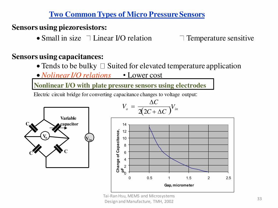
Two Common Types of Micro Pressure Sensors
Sensors using piezoresistors:
Small in size Linear I/O relation Temperature sensitive
Sensors using capacitances:
Tends to be bulky Suited for elevated temperature application
Nolinear I/O relations • Lower cost
Nonlinear I/O with plate pressure sensors using electrodes
Electric circuit bridge for converting capacitance changes to voltage output:
C
Vo Vin
C C
C
Variable
capacitor
in o V V 22C C
14
12
10
8
6
4
2
0
0 0.5 2 2.5 1 1.5
Gap, micrometer
Ch
an
ge
of
Ca
pa
cit
an
ce
,
pF
33 Tai-Ran Hsu, MEMS and Microsystems
Design and Manufacture, TMH, 2002

● Major problems in pressure sensors are in the system packaging
and protection of the diaphragm from the contacting
pressurized media, which are often corrosive, erosive, and at
high temperatures.
5) Pressure Sensors Contd..
34 Tai-Ran Hsu, MEMS and Microsystems
Design and Manufacture, TMH, 2002

6) Thermal Sensors ●Thermal sensors are used to monitor, or measure temperature in an
environment or of an engineering systems.
●Common thermal sensors involve thermocouples and thermopiles.
● Thermal sensors work on the principle of the electromotive forces (emf)
generated by heating the junction made by dissimilar materials (beads):
Bead
Heat Metal Wire A
Metal Wire B
V Voltage Output
V
Voltage Output
Metal Wire A
Metal Wire B
Cold
Junction Hot
Junction
Heat
i
i
i i
(a) A thermocouple (b) A dual junction thermocouple
The generated voltage (V) by a temperature rise at the bead (∆T) is:
V T
where β = Seebeck coefficient 35 Tai-Ran Hsu, MEMS and Microsystems
Design and Manufacture, TMH, 2002

The Seebeck coefficients for various thermocouples are:
Type Wire Materials Seebeck
Coefficient
(V/oC)
Range (oC) Range (mV)
E Chromel/Constantan 58.70 at 0oC -270 to 1000 -9.84 to 76.36
J Iron/Constantan 50.37 at 0oC -210 to 1200 -8.10 to 69.54
K Chromel/Alumel 39.48 at 0oC -270 to 1372 -6.55 to 54.87
R Platinum (10%)-Rh/Pt 10.19 at 600oC -50 to 1768 -0.24 to 18.70
T Copper/Constantan 38.74 at 0oC -270 to 400 -6.26 to 20.87
S Pt (13%)-Rh/Pt 11.35 at 600oC -50 to 1768 -0.23 to 21.11
Common thermocouples are of K and T types
Thermal Sensors contd..
36 Tai-Ran Hsu, MEMS and Microsystems
Design and Manufacture, TMH, 2002

Ho
t J
un
cti
on
Reg
ion
, Th
Thermopiles are made of connecting a series of thermocouples in parallel:
Thermocouples
Cold Junction
Region, Tc
V
The induced voltage (∆V) by the temperature change at the hot junction (∆T) is:
V N T
with N = number of thermocouple pairs in the thermopile.
Thermal Sensors contd..
37 Tai-Ran Hsu, MEMS and Microsystems
Design and Manufacture, TMH, 2002

A micro thermal sensor:
3.6 mm
Hot
Junction
Region
3.6
mm
Diaphragm: 1.6 mm dia x
1.3 m thick
32 Thermocouples
16 m wide
Cold Junction
Region
Top view 20
m
Hot Junction
Region
Thermocouples
Diaphragm
Silicon Rim
Support
Elevation
● 32 polysilicon-gold thermocouples
● dimension of thermopile is:
3.6 mm x 3.6 mm x 20 µm thick
● Typical output is 100 mV
● Response time is 50 ms
Thermal Sensors contd..
38 Tai-Ran Hsu, MEMS and Microsystems
Design and Manufacture, TMH, 2002

Working Principles for Microactuators
Micro
Actuating
Element
Output Action
Transduction Unit
Power
Supply
Power supply: Electrical current or voltage
Transduction unit: To covert the appropriate form of power supply into
the desired form of actions of the actuating element
Actuating element: A material or component that moves with power
supply
Output action: Usually in a prescribed motion
39 Tai-Ran Hsu, MEMS and Microsystems
Design and Manufacture, TMH, 2002

Actuators
• A mechanical device for moving or controlling something
• Important part of microsystem
• Four principal means of actuation
1. Thermal forces
2. Shape memory alloys
3. Piezoelectric crystals
4. Electrostatic forces
An actuator is designed to deliver a desired motion when driven by a
power source
Eg: electric relay, inkjet printer heads
• Driving power for actuators depends on its application
Eg: on-off switches deflection of bimetallic strip as a result of
resistance heating the strip with passing electric current
Motors, solenoid devices electromagnetic induction 40

Actuation Using Thermal Forces ● Solids deform when they are subjected to a temperature change (∆T)
● A solid rod with a length L will extend its length by ∆L = α∆T, in which α =
coefficient of thermal expansion (CTE) – a material property.
● When two materials with distinct CTE bond together and is subjected to a
temperature change, the compound material will change its geometry
as illustrated below with a compound beam (bimetallic strip)
Heat
1 2
1
2
●It will return to its original shape after the removal of the heat
●These compound beams are commonly used as microswitches, relays,
microclamps and valves in MEMS products.
41 Tai-Ran Hsu, MEMS and Microsystems
Design and Manufacture, TMH, 2002

Actuation Using Shape Memory Alloys (SMA)
Constraint Base
● SMA are the materials that have a “memory” of their original geometry (shape) at a
typically elevated temperature of production.
● These alloys are deformed into different geometry at typically room temperature.
● The deformed SMA structures will return to their original shapes when they are heated
to the elevated temperature at their productions.
● Nitinolor or Ti-Ni alloys are common SMAs.
● A microswitch actuated with SMA:
Shape Memory Alloy Strip
e.g. TiNi or Nitinolor
Resistance Heating Strip
Silicon Cantilever Beam
42 Tai-Ran Hsu, MEMS and Microsystems
Design and Manufacture, TMH, 2002

Actuation Using Piezoelectric Crystals
●A certain crystals, e.g., quartz exhibit an interesting behavior when subjected
to a mechanical deformation or an electric voltage. piezoelectric effect
●This behavior may be illustrated as follows:
V
Mechanical
Forces
Ap
pli
ed
Vo
ltag
e, V
Induced Mechanical
Deformation
Mechanical force induced
electric voltage
Electric voltage induced
mechanical deformation
●This peculiar behavior makes piezoelectric crystals an ideal candidate for
microactuation as illustrated in the following case:
43 Tai-Ran Hsu, MEMS and Microsystems
Design and Manufacture, TMH, 2002

A micro relay or microelectrical switch
Constraint Base
V
Electrodes
Piezoelectric
Silicon Cantilever Beam
Actuation Using Piezoelectric Crystals
44 Tai-Ran Hsu, MEMS and Microsystems
Design and Manufacture, TMH, 2002

Actuation Using Electrostatic Forces
● Electrostatic Force between Two Particles
● The Coulomb’s Law: The electrostatic force F is defined as the electrical
force of attraction or repulsion induced by an electric field E
A (with charge q)
B (with charge q’)
1 qq'
4 r 2 F The attraction or repulsive force:
where ε = permittivity of the medium between the two particles
= 8.85 x 10⁻¹² C2/N-m2 or 8.85 pF/m in vacuum (= εo)
r = Distance between the particles (m)
45 Tai-Ran Hsu, MEMS and Microsystems
Design and Manufacture, TMH, 2002

●Electrostatic Force Normal to Two Electrically Charged Plates:
V
Gap, d
Length, L
●The induced capacitance, C : d
WL d
r o r o C A
●The induced normal force, Fd is:
2 d 2 F d
1 r o WL
V 2
in which εr = relative permittivity of the dielectric material between the two
plates
Actuation Using Electrostatic Forces
46 Tai-Ran Hsu, MEMS and Microsystems
Design and Manufacture, TMH, 2002

● Electrostatic Force Parallel to Two Misaligned Electrically Charged
Plates:
d
L
Fd Fw
FL
W V
● Force in the “Width” direction:
2 d F w
1 r o L
V 2
● Force in the “Length” direction:
F L
1 r o W V 2
2 d
Actuation Using Electrostatic Forces
47 Tai-Ran Hsu, MEMS and Microsystems
Design and Manufacture, TMH, 2002

• These electrostatic forces are prime driving forces of
micro motors, comb drivers in micro grippers.
• Drawback of electrostatic actuation: force
generated by this method is usually low in magnitude.
• Application limited to actuators for optical switches,
microgrippers.
Tai-Ran Hsu, MEMS and Microsystems
Design and Manufacture, TMH, 2002 48
Actuation Using Electrostatic Forces

Microgrippers An essential component in microrobots in assembly
microassemblies and surgery
V
V
Closing
the gap,d
V
Aligning the
electrodes,L
Electrodes
Two gripping methods:
Gripping Arms
The normal plate electrodes
V - Not practical b/c
requiring more space.
The sliding plate electrodes
- Popular method. Can have
many sets to make “Comb drive” actuators
Applications of Microactuators
49 Tai-Ran Hsu, MEMS and Microsystems
Design and Manufacture, TMH, 2002

A Typical Microgripper with “Comb drive” Actuators:
Closure Arm
400 µm
100 µm
Drive Arm
10 µm V
160
140
120
100
80
60
40
20
0 0 20 100 120 40 60 80
Number of Electrode Pairs
Re
qu
ire
d V
olt
ag
e,
v
Arrangement of electrodes:
Drastic reduction in required
actuation voltage with increase
of number of pairs of electrodes:
50 Tai-Ran Hsu, MEMS and Microsystems
Design and Manufacture, TMH, 2002

Micromotors
Unlike traditional motors, the driving forces for micro motors is primarily the parallel
electrostatic forces between pairs of misaligned electrically charged plates (electrodes), as
will be demonstrated in the following two cases:
Linear stepping motors:
● Two sets of electrodes in the form of plates separated by dielectric material (e.g.
quartz film).
● One electrode set is fixed and the other may slide over with little friction.
● The two sets have slightly different pitch between electrodes Pitch:
w+w/3
Fixed set
electrodes:
Moving set
electrodes:
A’ B’ C’ D’ W/3
Dielectric material
B C D A
W W
W Step Movements
Applications of Microactuators
51 Tai-Ran Hsu, MEMS and Microsystems
Design and Manufacture, TMH, 2002

● Energize the set A-A’ will generate a force pulling A’ over A due to initial misalignment.
● Once A and A’ are aligned, the pair B and B’ become misaligned.
● Energize the misaligned B-B’ will generate electrostatic force pulling B’ over B.
● It is now with C’ and C being misaligned.
● Energize C’ and C will produce another step movement of the moving set over the
stationary set.
● Repeat the same procedure will cause continuous movements of the moving sets
● The step size of the motion = w/3, or the size of preset mismatch of the pitch between
the two electrode sets.
Fixed set
e lectrodes:
Moving set
e lectrodes:
A’ B’ C’ D’
Pitch:
w+w/3 W/3
Dielectric material
B C D A
W W
W Step Movements
Applications of Microactuators
52 Tai-Ran Hsu, MEMS and Microsystems
Design and Manufacture, TMH, 2002

Rotary stepping motors:
● Involve two sets of electrodes- one set for the rotor and the other for the stator.
● Dielectric material between rotor and stator is air.
● There is preset mismatch of pitches of the electrodes in the two sets.
Applications of Microactuators
53 Tai-Ran Hsu, MEMS and Microsystems
Design and Manufacture, TMH, 2002

Stator
Rotor Gear for
transmitting
torque
● Working principle of this rotary motor is similar to that in linear motors.
A micro motor produced by Karlsruhe Nuclear Research Center, Germany:
Applications of Microactuators
54 Tai-Ran Hsu, MEMS and Microsystems
Design and Manufacture, TMH, 2002

Microvalves
Electric Resistance
Heating Rings Flexible Silicon Diaphragm
Si licon
Base
Constraint Base
INLET FLOW
FLOW OUTLET Centerline
● A special microvalve designed by Jerman in 1990.
● Circular in geometry, with diaphragm of 2.5 mm in diameter x 10 µm thick.
● The valve is actuated by thermal force generated by heating rings.
● Heating ring is made of aluminum films 5 µm thick.
● The valve has a capacity of 300 cm3/min at a fluid pressure of 100 psig.
● Power consumption is 1.5 W.
Applications of Microactuators
55 Tai-Ran Hsu, MEMS and Microsystems
Design and Manufacture, TMH, 2002

Micropumps
Low Pressure
Fluid Inlet High Pressure
Fluid Outlet
Electrode
O utlet
Che ck
Valve
Pumping Chamber Inlet Che ck
Valve
Constraint
Base
V
1. Electrostatically actuated micropump:
● An electrostatic actuated pump in 1992.
● The pump is of square geometry with 4 mm x 4mm x 25 µm thick.
● The gap between the diaphragm and the electrode is 4 µm.
● Pumping rate is 70 µL/min at 25 Hz.
Deformable Silicon
Diaphragm
Applications of Microactuators
56 Tai-Ran Hsu, MEMS and Microsystems
Design and Manufacture, TMH, 2002

F V
Flexible Tube
Wall
2. Piezoelectrically actuated pump:
● An effective way to pump fluid through capillary tubes.
● Tube wall is flexible.
● Outside tube wall is coated with piezoelectric crystal film, e.g. ZnO with
aluminum interdigital transducers (IDTs).
● Radio-frequency voltage is applied to the IDTs, resulting in mechanical
squeezing in section of the tube (similar to the squeezing of toothpaste)
● Smooth flow with “uniform” velocity profile across the tube cross section.
Piezoelectric coating
with transducer
Flow
57 Tai-Ran Hsu, MEMS and Microsystems
Design and Manufacture, TMH, 2002

Microaccelerometers
● Accelerometers are used to measure dynamic forces associated with
moving objects.
● These forces are related to the velocity and acceleration of the moving objects.
● Traditionally an accelerometer is used to measure such forces.
● A typical accelerometer consists of a “proof mass” supported by a spring and a
“dashpot” for damping of the vibrating proof mass:
The accelerometer is
attached to the vibrating
solid body
Spring
k
Mass
M Dashpot
with
dampin
g C Vibrating
Solid Body
58 Tai-Ran Hsu, MEMS and Microsystems
Design and Manufacture, TMH, 2002

Spring
k
Mass
M
Dashpot
with
damping
C
Vibrating
Solid Body
The accelerometer is attached
to the vibrating solid body
The instantaneous displacement of the mass y(t)
induced by the attached moving solid body is
measured and recorded with respect to time, t.
The associated velocity, V(t) and the acceleration
α(t) may be obtained by the following derivatives:
d 2 y(t)
dt dt dt 2
dy(t ) dy(t ) V (t) and (t)
The associated dynamic force of induced by the moving solid is thus obtained by using
the Newton’s law, i.e. F(t) = M α(t), in which M = the mass of the moving solid.
In miniaturizing the accelerometers to the micro-scale, there is no room for the coil
spring and the dashpot for damping on the vibrating mass.
Alternative substitutes for the coil spring, dashpot, and even the proof mass need to
be found.
Microaccelerometers contd..
59 Tai-Ran Hsu, MEMS and Microsystems
Design and Manufacture, TMH, 2002

● There are two types micro accelerometers available.
(1) The cantilever beam accelerometer:
Mass, M
Piezoresistor Silicon Cantilever
Beam
Constraint Base
Casing
Constraint Base
Vibrating Base
In this design: Cantilever beam = coil spring;
Surrounding viscous fluid = dashpot for damping of the proof mass
The movement of the proof mass is carried out by the attached piezoresistor.
Microaccelerometers contd..
60 Tai-Ran Hsu, MEMS and Microsystems
Design and Manufacture, TMH, 2002

(2) Balanced force micro accelerometer:
● This is the concept used in the “air-bag” deployment sensor in automobiles
● In this design: Plate beam = proof mass;
Two end tethers = springs
Surrounding air = dashpot
● The movement of the proof mass is carried out by measuring the change of
capacitances between the pairs of electrodes.
Stationary
electrodes
Moving electrode
Microaccelerometers contd..
61 Tai-Ran Hsu, MEMS and Microsystems
Design and Manufacture, TMH, 2002

Review of Mechanical concepts
62 Thomas B. Jones, Electromechanics and
MEMS, Cambridge University Press, 2001

Chang Liu, Foundations of MEMS, Pearson
2012
63
Stress
• Stress is developed in response to mechanical loading.
• Newton’s three laws of motion is the foundation for analyzing the
static and dynamic behaviors of MEMS devices under loading.
• These laws are used to analyze force distribution inside a material,
which gives rise to stress and strain.

Chang Liu, Foundations of MEMS, Pearson
2012
64
Fig: Force balance analysis

Chang Liu, Foundations of MEMS, Pearson
2012
65
• Consider a bar firmly embedded in a brick wall with an axial force F
applied at the end.
• Since the force is transmitted through the bar to the wall, the wall must
produce a reaction according to the Newton’s Third Law.
• The wall would act on the left end of the bar with an unknown force.
• To expose and quantify this force, we imaginarily remove the wall, and
replace it with the actions it imparts on the bar.
• This free-body diagram of the bar clearly reveals that the wall must
provide an axial force with equal magnitude but opposite direction to the
applied force, so that the total force on the bar is zero to maintain its
stationary status (Newton’s First Law).
• We can use this technique to expose and quantify hidden forces and
stresses at any section.
• Since the bar is in equilibrium, any part of it must be in equilibrium as
well.
• We can pick an arbitrary section of interest, and imaginarily cut the bar
into two halves.
• Since a force is applied at the free end of the bar, an equal but opposite
force must develop at the cross section.

Chang Liu, Foundations of MEMS, Pearson
2012
66
Fig: Force and moment balance analysis.

Chang Liu, Foundations of MEMS, Pearson
2012
67
• Now let us consider the same bar under a force acting in the transverse
direction.
• Isolate the bar: The sum of forces and moments acting on the isolated
bar must be zero.
• For the net force to be zero, a force of same magnitude but opposite
sign must act on the end of the bar attached to the wall.
• The pair of force, however, creates a torque (also referred to as a couple
or a moment in mechanics) with the magnitude being F times L, the
length of the bar.
• A reactive torque, with the magnitude of F times L but opposite sign,
must act on the end of the bar attached to the wall.
The imaginarily cut section on the piece to the left would have exactly
opposite force and torque as the opposing surface (according Newton’s Third Law).
• The magnitude of the sum of torques on the left-hand piece is equal to ,
which equals the force multiplied by the length of the left-hand piece.
• The net force and torque acting on the left hand piece are both zero.

Chang Liu, Foundations of MEMS, Pearson
2012
68
Definitions of Stress and Strain
Mechanical stresses fall into two categories
1. normal stress
2. shear stress.
Fig: Normal stress and shear stress.

Chang Liu, Foundations of MEMS, Pearson
2012
69
• If we pull on the rod in its longitudinal direction, it will
experience tension and the length of the rod will increase.
• The internal stress in the rod is exposed if we make an imaginary cut
through the rod at section.
• The intensity of this force is called the stress.
• If the stress acts in a direction perpendicular to the cross section, it is
called a normal stress.
• The normal stress, commonly denoted as is defined as the force applied on
a given area (A).
The SI unit of stress is N/m2 or Pa.
• A normal stress can be tensile (as in the case of pulling along the rod) or
compressive (as in the case of pushing along the rod).
• The polarity of normal stress can also be determined by
isolating an infinitesimally small volume inside the bar.
• If the volume is pulled in one particular axis, the stress is tensile; if the
volume is pushed, the stress is compressive.

Chang Liu, Foundations of MEMS, Pearson
2012
70
• The unit elongation of the rod represents the strain.
• In this case, it is called normal strain since the direction of the strain is
perpendicular to the cross section of the beam.
• Suppose the steel bar has an original length L0. Under a given normal
stress the rod is extended to a length of L.
• The resultant strain in the bar is defined as

Chang Liu, Foundations of MEMS, Pearson
2012
71
• The applied longitudinal stress along the x-axis not only produces a
longitudinal elongation in the direction of the stress, but a reduction of
cross-sectional area as well.
• The relative dimensional change in the y and z directions can be
expressed as εy and εz.
• This general material characteristic is captured by a term called the
Poisson’s ratio, which is defined as the ratio between transverse and
longitudinal elongations.

Chang Liu, Foundations of MEMS, Pearson
2012
72
• Stress and strain are closely related.
• Under small deformation, the stress and the strain terms are proportional to
each other according to the Hooke’s law.
• The proportion constant, E, is called the modulus of elasticity.
• The modulus of elasticity, often called the Young’s modulus, is an intrinsic
property of a material.
• It is a constant for a given material, irrespective of the shape and
dimensions of the mechanical element.
• Atoms are held together with atomic forces.
• If one imagines inter-atomic force acting as springs to provide restoring
force when atoms are pulled apart or pushed together, the modulus of
elasticity is the measure of the stiffness of the inter-atomic spring near the
equilibrium point.

73
• Shear stresses can be developed under different force loading conditions.
• One of the simplest ways to generate a pure shear loading is illustrated in
the Figure, with a pair of forces acting on opposite faces of a cube
Chang Liu, Foundations of MEMS, Pearson
2012

74
• The magnitude of the shear stress is defined as
The unit of τ is N/m2
• Shear stress has no tendency to elongate or shorten the element in the x,
y, and z directions.
• Shear stresses produce a change in the shape of the element.
• The original element shown here, which is a rectangular parallelepiped, is
deformed into an oblique parallelepiped.
• Shear strain ϒ, defined as the extent of rotational displacement, is
• The shear stress is unit less
• It represents the angular displacement expressed in the unit of radians.
Chang Liu, Foundations of MEMS, Pearson
2012

75
• The shear stress and strain are also related to each other by a
proportional constant, called the shear modulus of elasticity, G.
• The expression of G is simply the ratio of τ and ϒ
The unit of G is N/m2.
• The value of G depends on the material, not the shape and dimensions
of an object.
• For a given materials, E, G, and the Poisson’s ratio are linked through
the relationship
Chang Liu, Foundations of MEMS, Pearson
2012

76
Stress and Strain relation
• Stress–strain relation is decided
by a tensile test.
• A rod with precise dimensions,
calibrated crystalline
orientation and smooth surface
finish is subjected to a tension
force applied in the
longitudinal direction.
• The amount of relative
displacement and the applied
stress are plotted on a stress-
strain curve until the beam
breaks.
Fig: generic stress-strain curve
Chang Liu, Foundations of MEMS, Pearson
2012

77
Inferences from stress-strain curve
1. At low levels of applied stress and strain, the stress value increases
proportionally with respect to the developed strain, with the
proportional constant being the Young’s modulus.
2. This segment of the stress-strain curve is called the elastic
deformation regime.
3. If the stress is removed, the material will return to its
original shape.
4. This force loading can be repeated for many times.
5. As the stress exceeds a certain level, the material enters the plastic
deformation regime.
6. In this regime, the amount of stress and strain does not follow a linear
relationship anymore.
7. Furthermore, deformation cannot be fully recovered after the external
loading is removed.
Bend a metal paper clip wire slightly, it will always return to its
original shape.
If the wire is bent beyond a certain angle, the clip will never return to
original shapes again.
Chang Liu, Foundations of MEMS, Pearson
2012

78
Inferences from stress-strain curve
8. Plastic deformation is said to have occurred.
9. Stress-strain curves for materials in compression differ from those in
tension
10. The stress-strain curve has two noticeable points—yield point and
fracture point.
11. Before the yield point is reached, the material remains elastic.
12. Between the yield point and the fracture point, the specimen undergoes
plastic deformation.
13. At the fracture point, the specimen suffers from irreversible failure.
14. The y-coordinate of the yield point is the yield strength of the
material.
15. The y-coordinate of the fracture point is designated the ultimate
strength (or the fracture strength) of the material.
A material is strong if it has high yield strength or ultimate strength
silicon is even stronger than stainless steel.
Chang Liu, Foundations of MEMS, Pearson
2012

79
• For many metals the generic
relationship depicted in previous
figure is true.
• All materials do not exhibit this
generic stress–strain relationship.
• Some representative curves for
different classes of materials are
shown in Figure.
• Includes brittle materials (such as
silicon) and soft rubber, both are
used extensively in MEMS.
Fig: Stress-strain relation
Chang Liu, Foundations of MEMS, Pearson
2012

80
Important properties
• Ductility is an important mechanical property.
• It is a measure of the degree of plastic deformation that has been
sustained at the point of fracture.
• A material that experiences very little or no plastic deformation
upon fracture is termed brittle.
• Silicon is a brittle material, which fails in tension with only little
elongation after the proportional limit is exceeded.
• Ductility may be expressed quantitatively as either percent
elongation or percent reduction in area.
Chang Liu, Foundations of MEMS, Pearson
2012

81
Important properties
• Toughness is a mechanical measure of the ability of a material to
absorb energy up to fracture.
• For a static situation, toughness may be ascertained from the result
of the tensile stress-strain test.
• It is the area under the stress-strain curve up to the point of fracture.
• For a material to be tough, it must display both strength and
ductility.
• Resilience is the capacity of a material to absorb energy when it is
deformed elastically and then, upon unloading, to have this energy
recovered.
Chang Liu, Foundations of MEMS, Pearson
2012

Chang Liu, Foundations of MEMS, Pearson
2012
82
Stress and Strain relation
• Stress and strain are tensors.
• Their relationship can be conveniently expressed in matrix form in which
stress and strain are expressed as vectors.
To visualize vector components of stress and strain, let us isolate a unit cube
from inside a material and consider stress components acting on it.

Chang Liu, Foundations of MEMS, Pearson
2012
83
• A cube has six faces.
• Consequently, there are 12 possible shear force components—two for each face.
These are not all independent
• Each pair of shear stress components acting on parallel faces but along the same
axis have equal magnitude and opposite directions for force balance (Newton’s first law).
• This reduces the number of independent shear stress components to six.
• Each component is identified by two subscript letters.
• The first letter in the subscript indicates the normal direction of the facet on
which the stress is applied to, while the second letter indicates the direction of
the stress component.
• Based on torque balance, two shear stress components acting on two facets but
pointing towards a common edge have the same magnitude.
τxy=τyx τxz=τzx τzy=τyz
• In other words, equal shear stresses always exist on mutually perpendicular
planes.
• The independent number of shear stress components is reduced to three.

Chang Liu, Foundations of MEMS, Pearson
2012
84
• There are six possible normal stress components—one for each face of a
cube.
• Under equilibrium conditions, the normal stress components acting on
opposite facets must have the same magnitude and point to opposite
directions.
• Therefore, there are three independent normal stress components.
• Normal stress components are labeled σ with two subscript letters.
Overall, in a rectangular coordinate system under motion equilibrium, there
are three independent normal stresses and three shear ones.
1. Normal stress components σxx, σyy, and σzz are simply noted as T1, T2 and
T3 respectively.
2. Shear stress components τyz, τxz, and τxy are simply noted as T4, T5 and T6
respectively.

Chang Liu, Foundations of MEMS, Pearson
2012
85
• Correspondingly, there are three independent strains ( through ) and three
shear strains ( through ).
• The general matrix equation between stress and strain, is
• In short-hand form, the expression is
• The coefficient matrix C is called the stiffness matrix.

Chang Liu, Foundations of MEMS, Pearson
2012
86
• The strain matrix is a product of the compliance matrix, S, and the stress
tensor, according to the following matrix expression
• The expression in short hand form is
• The compliance matrix S is the inverse of the stiffness matrix.
In short hand notation,
Note the stiffness matrix is denoted by the letter C, whereas the compliance
matrix is denoted by the letter S
Related Documents