EasyBuild- Assembly Manual Enclosure for Desktop CNC /3D Systems STEPCRAFT 300/ 420 Original assembly manual date of 01.07.2017

Welcome message from author
This document is posted to help you gain knowledge. Please leave a comment to let me know what you think about it! Share it to your friends and learn new things together.
Transcript
EasyBuild-Assembly
Manual
Enclosure for Desktop CNC /3D Systems
STEPCRAFT 300/ 420
Original assembly manualdate of 01.07.2017
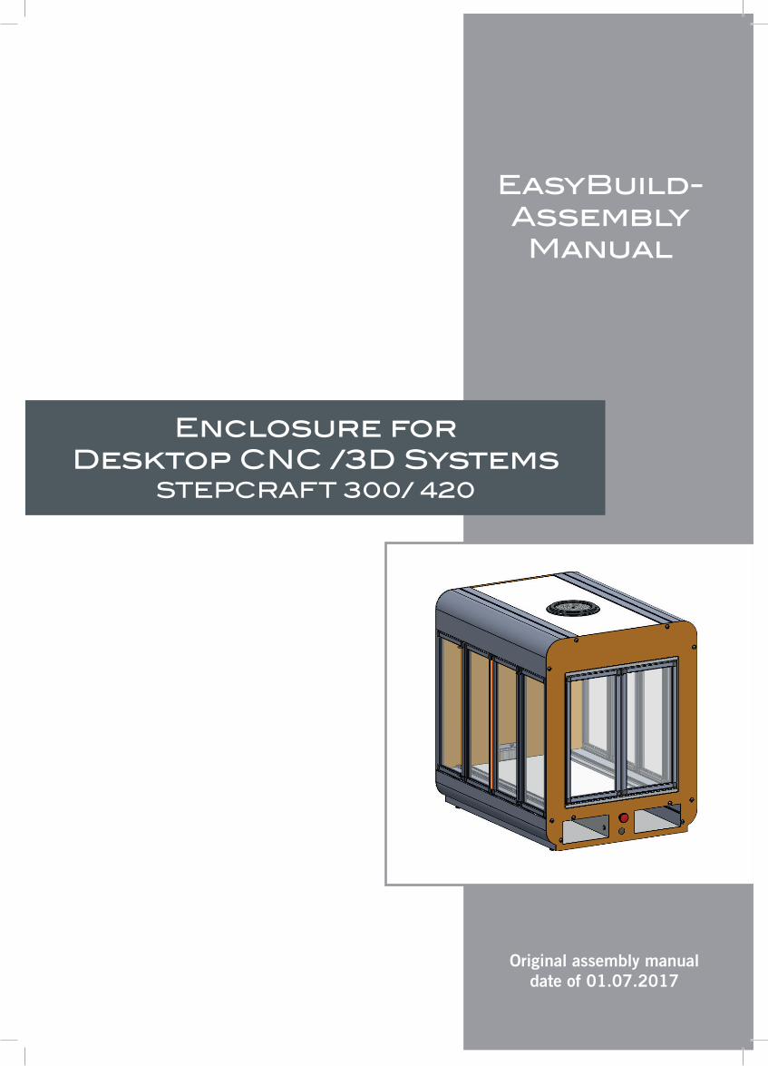
Dear customer,
thank you very much for purchasing our high-quality kit of an enclosure of your Stepcraft Desktop CNC /3D System. This manual will take you through every step of the assembly.
Please read the entire manual carefully before starting assembly. This way, you obtain an overview of the steps required which will help you avoid unneccessary mistakes. Please take care to use the the correct parts in the correct orientation as some parts differ only minimally. Please let a second person assist you in the assembly.
Before beginning the assembly process, please verify that you have all of the required parts in your kit using the list below. Stepcraft provides video support with certain assembly steps. Simply scan the related QR code with your smartphone. If you do not have a smartphone, please enter the following URL in your web browser: www.stepcraft-systems.com/enclosure/xx-xx (replace xx-xx with the number under the QR code).
STEPCRAFT has taken extreme care to ensure the correctness of the information contained in this manual. We accept no liability for damage in materials or injury to persons caused by assembling the enclosure. You are responsible for the safe operation of your Stepcraft Desktop CNC /3D System and its accessories.
2 3
4 6
8
1
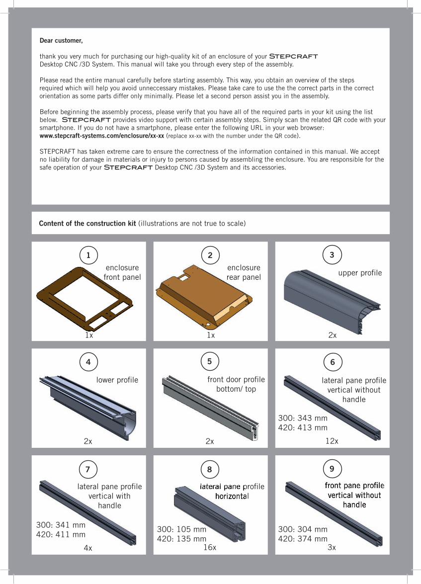
enclosure front panel
1x
Content of the construction kit (illustrations are not true to scale)
1x
enclosure rear panel
2x
upper pro�le
lower pro�le lateral pane pro�le vertical without
handle
lateral pane pro�le horizontal
lateral pane pro�le horizontal
9
front pane pro�le vertical without
handle
front pane pro�le vertical without
handle
5
front door pro�le bottom/ top
7
lateral pane pro�le vertical with
handle
2x 2x 12x
4x 16x 3x
300: 343 mm420: 413 mm
300: 105 mm420: 135 mm
300: 341 mm420: 411 mm
300: 304 mm420: 374 mm
13
16
1514
17 18
23 24
1110
front pane pro�le vertical with
handle
front pane pro�le horizontal
12
rubber seal (silicone)
connection pro�le (silicone)
side pane front pane
8x 2x
1x
base plate base plate partition
25 26
slot nut, lockable
slot nut, loose slot nut, loose external
6x 6x
machine table
pivot pin
front pane
2x
19 20 21
1x
top plate plastic corner
45x
circular brush
1x 4x
1x
1x
22
strip brush cable outlet
1x 4x 20x
300: 120 mm420: 165 mm
300: 302 mm420: 372 mm
300: 4,50 m420: 5,50 m
300: 0x420: 2x
300: 311 x 127 mm420: 381 x 172 mm
300: 225 x 563 mm420: 315 x 683 mm
300: 244 x 563 mm420: 334 x 683 mm
300: 373 x 563 mm420: 463 x 683 mm
300: 350 x 112 mm420: 420 x 142 mm
(silicone)
black300: 1,9 m420: 2 m
orange300: 0,8 m420: 0,9 m

37
32 33 34 35 36
�ange screw, M5 x 12 mm
2x 2x6x6x20x
spacer,M5 x 50 mm
1x
42 43 44 45 46
47 48 49 50 51
38 39 40 41
cam lock screwwooden dowel cam screw
end switch with cable supply
locking nut, M5
set screw,M4 x 5 mm
�ange screw, M6 x 20 mm
emergency switch emergency switch cable
cable conduit 6/4 mm
hole plug 8 mm
hole plug 36 mm
15 pin Sub-D cable
grounding cable set incl. serrated
lock washer
4x
3x 1x
1x1x
27 28 29 30 31
door handle
spacer M3 x 10 mm
4x 4x 6x
socket head screw, M6 x 30 mm
pressure pin
10x
plastic foot
1x
1x 1x
controller board
button head cap screw, M3 x 6 mm
wood screw 3,5 x 15 mm
3x
10x
300: 0x420: 4x
300: 0x420: 4x
300: 0x420: 4x
2,60 m
socket head screw, M5 x 30 mm
300: 0,75 m420: 0,88 m
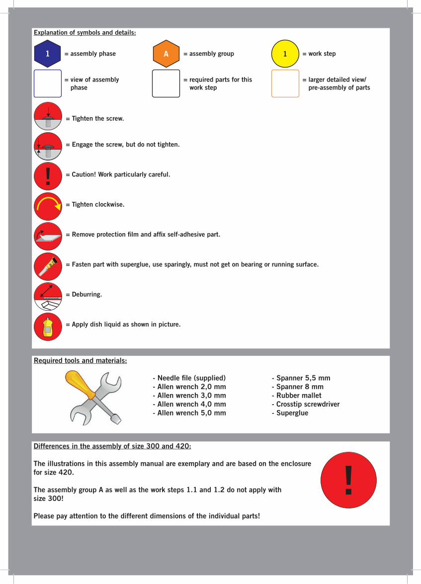
Explanation of symbols and details:
Required tools and materials:
- Needle �le (supplied) - Spanner 5,5 mm - Allen wrench 2,0 mm - Spanner 8 mm - Allen wrench 3,0 mm - Rubber mallet - Allen wrench 4,0 mm - Crosstip screwdriver - Allen wrench 5,0 mm - Superglue
1 A 1= assembly phase = assembly group = work step
= view of assembly phase
= required parts for this work step
= larger detailed view/ pre-assembly of parts
= Tighten the screw.
= Engage the screw, but do not tighten.
= Caution! Work particularly careful.
= Tighten clockwise.
= Remove protection �lm and af�x self-adhesive part.
= Fasten part with superglue, use sparingly, must not get on bearing or running surface.
= Deburring.
= Apply dish liquid as shown in picture.
!
Differences in the assembly of size 300 and 420:
The illustrations in this assembly manual are exemplary and are based on the enclosure for size 420.
The assembly group A as well as the work steps 1.1 and 1.2 do not apply with size 300!
Please pay attention to the different dimensions of the individual parts!
!

1
41
2x
39
2x
1.1
4016
17
1x
A
4x1x
! Please produce 2x !
Base frameAssembly group A and work steps 1.1 and 1.2 only
apply for size 420!
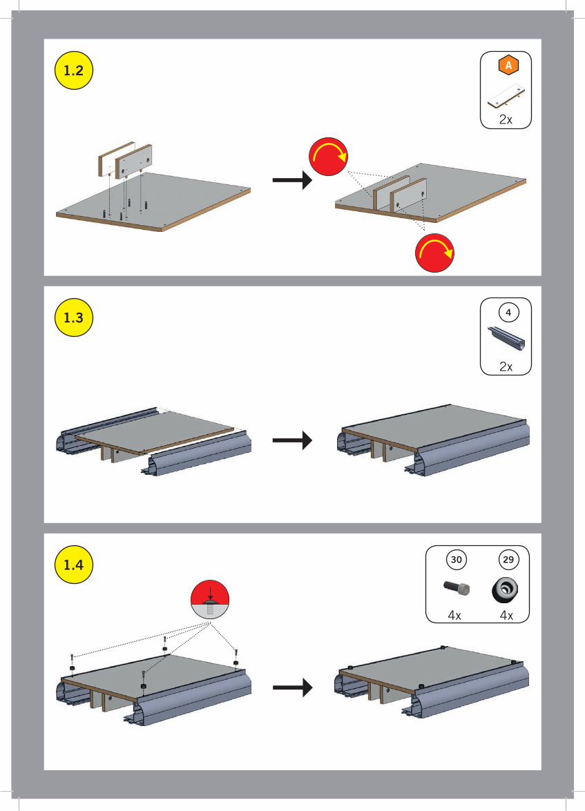
1.2
1.3
4
1.4
2930
A
2x
4x 4x
2x
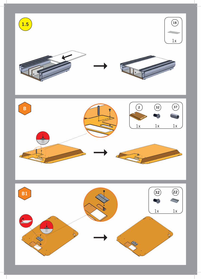
1.5
18
37322B
2232B1
1x 1x
1x1x1x
1x

1.6
33
B
Preparatory steps for all doors:
6x1x
B
Before attaching the plastic corners it is especially important that the leading edges of all pro�les are deburred with the supplied needle �le in order to avoid blocking due to plastic chips.
!

12
20
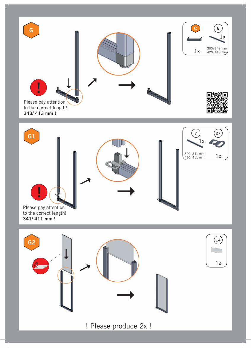
C
C1
C2
8 20
300: 105 mm420: 135 mm
Please pay attention to the correct length! 105/ 135 mm !
!!
For an easier assembly of the plastic corners, please turn the pro�le and use the rubber mallet to �x it to the corner!
! Please produce 16x !
1x
1x
300: 107 mm420: 137 mm
1x

27
14
D
D1
D2
6
!
Please pay attention to the correct length! 343/ 413 mm !
Please pay attention to the correct length! 341/ 411 mm !
!
7
C
! Please produce 2x !
1x
1x
1x
1x
1x
300: 343 mm420: 413 mm
300: 341 mm420: 411 mm

14
E
E1
E2
6
!Please pay attention to the correct length! 343/ 413 mm !
Please pay attention to the correct length! 343/ 413 mm !
!
6
C
! Please produce 2x !
1x
1x
1x
1x
300: 343 mm420: 413 mm
300: 343 mm420: 413 mm

6
14
F
F1
F2
6
!Please pay attention to the correct length! 343/ 413 mm !
Please pay attention to the correct length! 343/ 413 mm !
!
C
! Please produce 2x !
1x
1x
1x
1x
300: 343 mm420: 413 mm
300: 343 mm420: 413 mm
14
G
G1
G2
6
!Please pay attention to the correct length! 343/ 413 mm !
Please pay attention to the correct length! 341/ 411 mm !
!
C
277
! Please produce 2x !
1x
1x
1x
1x
1x300: 343 mm420: 413 mm
300: 341 mm420: 411 mm
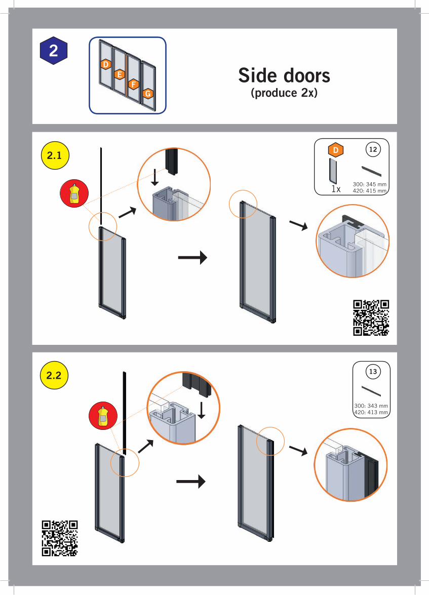
2
12
2.2 13
2.1
D
1x
Side doors(produce 2x)
300: 345 mm420: 415 mm
300: 343 mm420: 413 mm
DE
FG

13
C2.3
2.4
2.5
27
E
1x1x
1x
300: 345 mm420: 415 mm
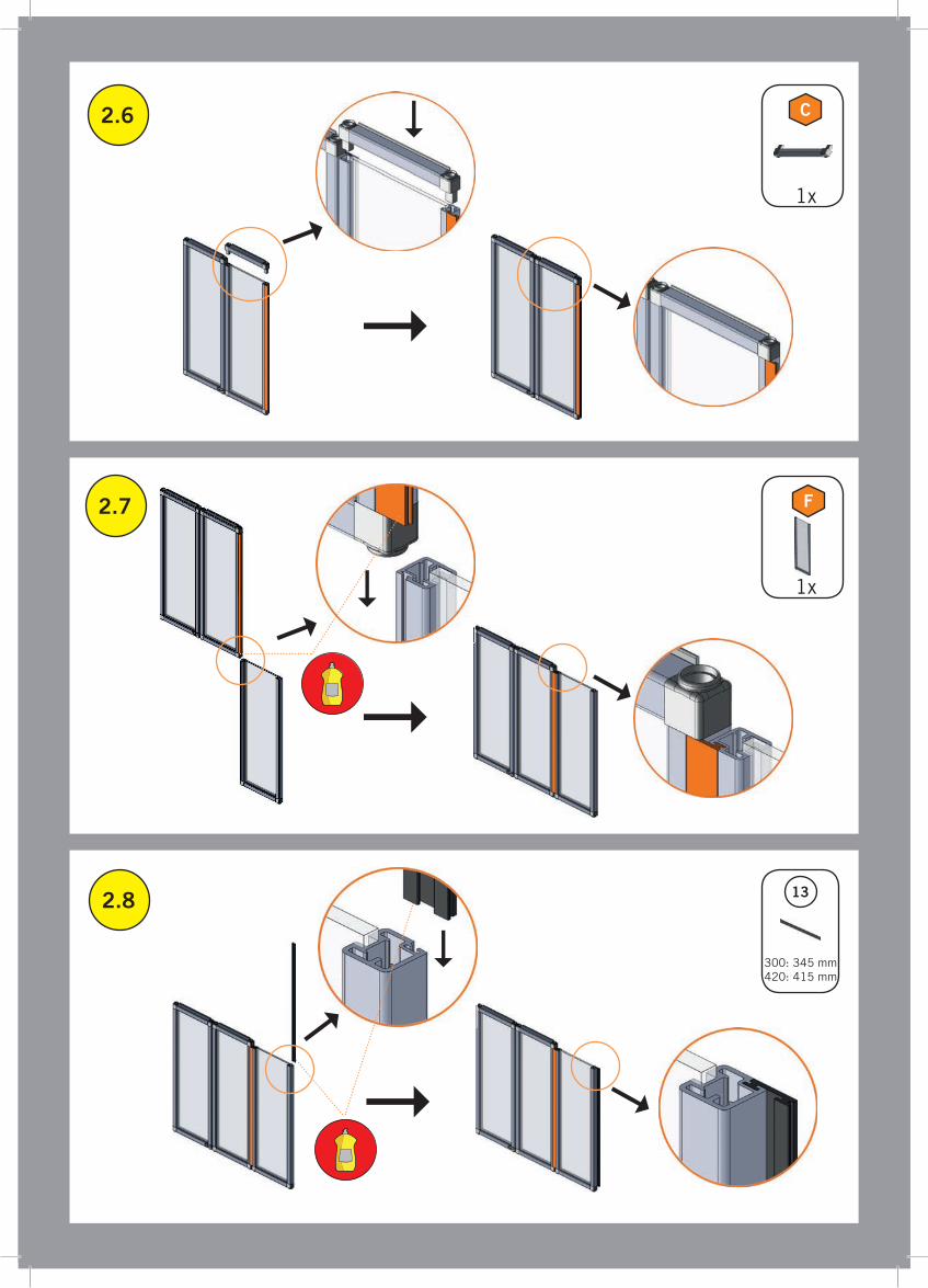
C2.6
2.7
2.8
F
13
1x
1x
300: 345 mm420: 415 mm

12
C2.9
2.10
2.11
G
1x
1x
300: 345 mm420: 415 mm

2.13
2.14
C 27
2826
2826
2.12
1x 1x
4x 2x
4x 2x
! Please produce 2x !

3
34
3.2
1x
3.1
1x
2423
1x
25
1x1x1x
2
Upper frame
1
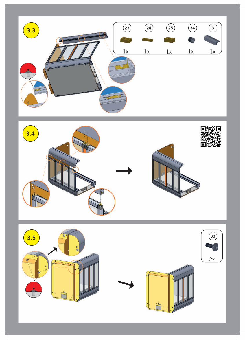
3.3
3.4
3.5
3
33
2x
342423 25
1x1x 1x1x1x
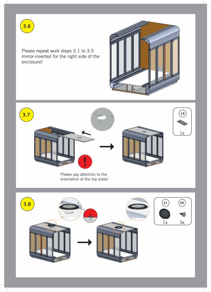
3.6
3.7
3.8 50
Please repeat work steps 3.1 to 3.5 mirror-inverted for the right side of the enclosure!
19
21
1x
1x
3x
Please pay attention to the orientation of the top plate!
!
12
20
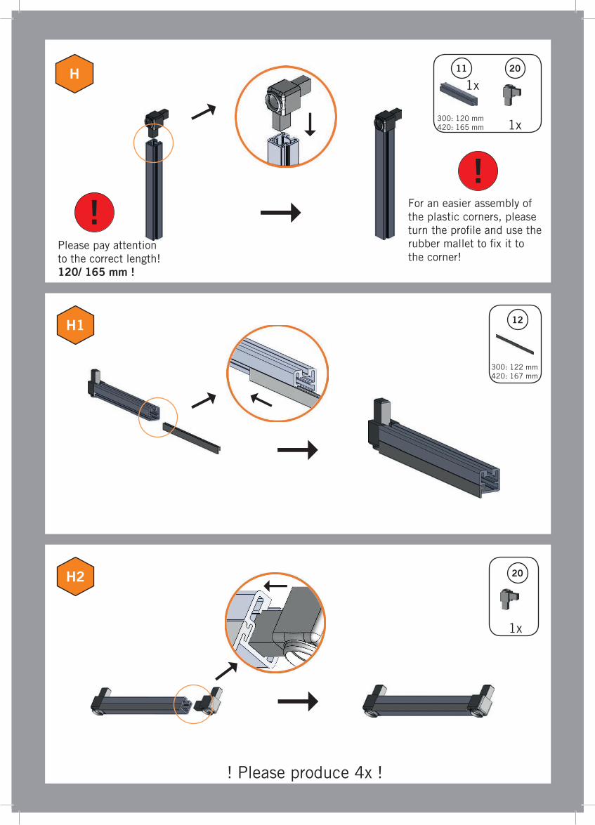
H
H1
H2
11 20
Please pay attention to the correct length! 120/ 165 mm !
!!
! Please produce 4x !
1x
1x
1x
300: 120 mm420: 165 mm
300: 122 mm420: 167 mm
For an easier assembly of the plastic corners, please turn the pro�le and use the rubber mallet to �x it to the corner!
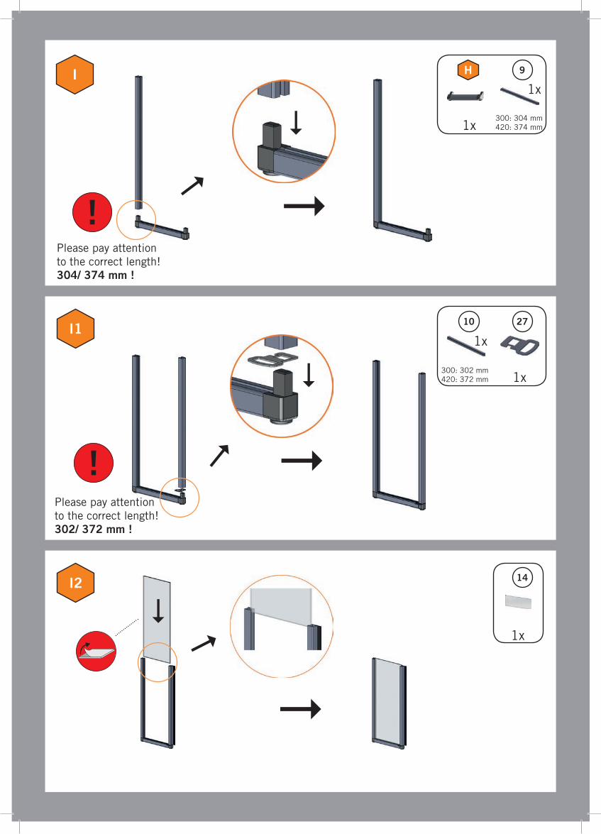
14
I
I1
I2
9
!Please pay attention to the correct length! 304/ 374 mm !
Please pay attention to the correct length! 302/ 372 mm !
!
H
2710
1x
1x
1x
1x
1x
300: 304 mm420: 374 mm
300: 302 mm420: 372 mm

9
14
J
J1
J2
9
!Please pay attention to the correct length! 304/ 374 mm !
Please pay attention to the correct length! 304/ 374 mm !
!
H
1x
1x
1x
1x
300: 304 mm420: 374 mm
300: 304 mm420: 374 mm
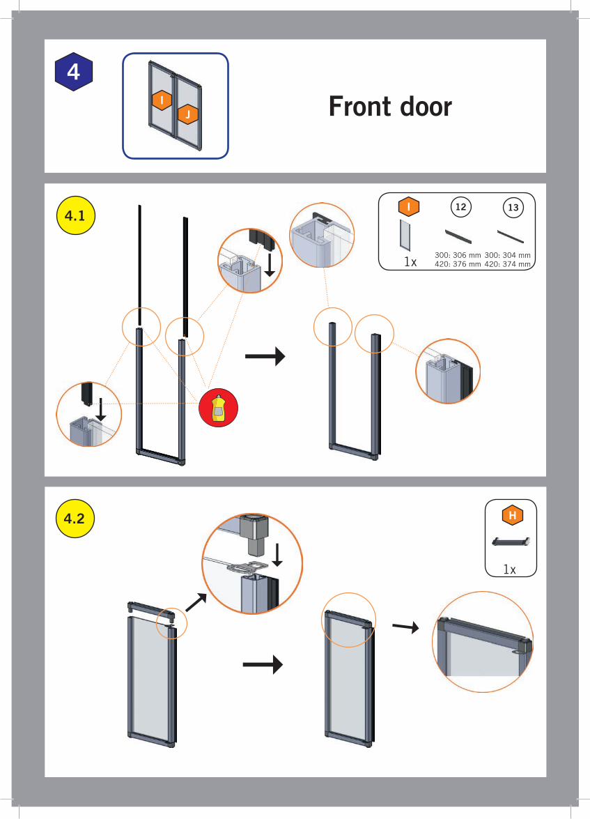
4
13
4.2
4.1
12I
H
Front door
1x
1x300: 304 mm420: 374 mm
300: 306 mm420: 376 mm
IJ

4.3
J
H4.5
4.4 12
1x
1x
300: 306 mm420: 376 mm
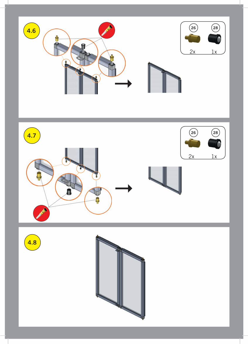
4.6
4.7
4.8
2826
2826
1x
1x2x
2x

K
L
L1
2523 345
2523 345
42
43
1x1x 1x1x
1x 1x1x1x
1x
!
Guide the cable end �rstly th-rough the cable conduit and afterwards carefully through the pro�le.
300: 875 mm420: 1115 mm
5
475.2
5.1
441
1x 1x 1x
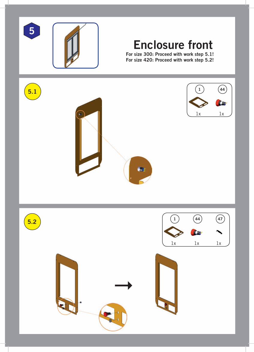
Enclosure frontFor size 300: Proceed with work step 5.1!For size 420: Proceed with work step 5.2!
441
1x 1x

5.3
Please degrease the surface �rst!
5.5 45
1x 1x
5 43
5.44L
1x 1x
Size 300: Size 420:
Size 300: Please shorten the cable conduit and pull it carefully over the emergency switch cable.
!
K
1x
300: 613 mm420: not applicable
!
!
Please degrease surface �rst!

6.1
6
3 35
1x 6x
Final assembly
6.2 4342
Guide the cable end �rstly through the cable conduit and afterwards through the pro�le.
2x! 300: 548 mm420: 668 mm
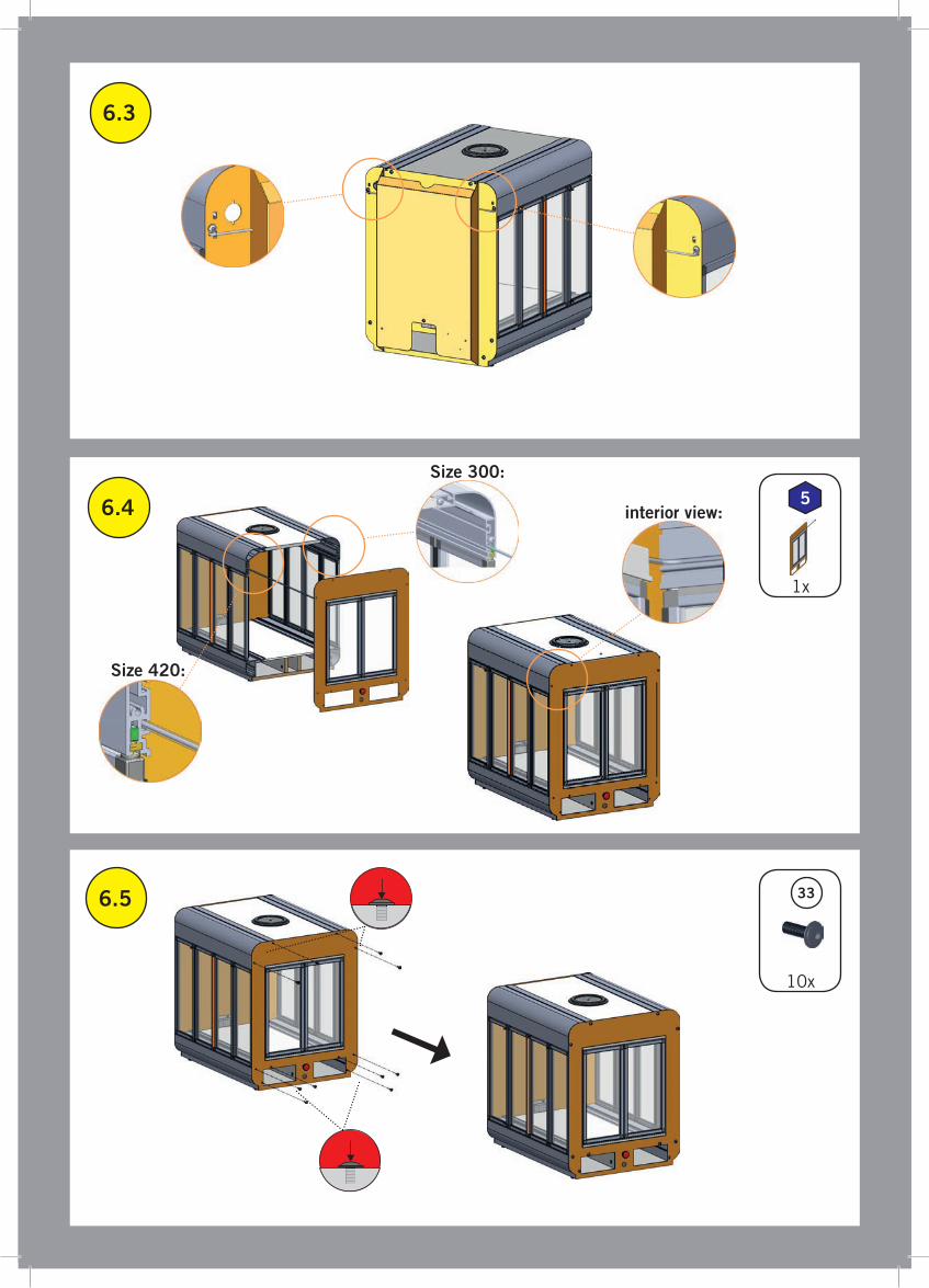
6.3
6.4
6.5 33
10x
1x
5
Size 300:
Size 420:
interior view:

6.6
6.7
3836
2x 2x
Desktop CNC /3D System
Insertion tool/ Switch-Box
Emergency stop
LED power (opt.)
LED switch (opt.)
12V power (opt.)
Doo
r ri
ght
Doo
r fr
ont
Doo
r le
ft

6.8
6.9
4838
2x 1x
31
6x
With the socket head screws M5 x 30 mm the Stepcraft Desktop CNC /3D System, control devices or the Switch-Box and drawers can be �xed in their �nal position in the enclosure.

STEPCRAFT GmbH & Co. KGAn der Beile 258708 MendenGermany
Phone: +49 (2373) 179 11 60Fax: +49 (2373) 179 11 [email protected]
© STEPCRAFT 2017
Enclosure for Desktop CNC /3D Systems
STEPCRAFT 300/ 420
Related Documents