Final Geotechnical Engineering Report East Riverfront Transportation Improvement City of Richmond, Virginia DMY Project Number: GEO 123015.10 November 15, 2016 Prepared for Whitman, Requardt & Associates, LLP (WRA) 9030 Stony Point Parkway, Suite 220 Richmond, VA 23235 Prepared by DMY Inc. 14241 Midlothian Turnpike, Suite 230 Midlothian, VA 23113

Welcome message from author
This document is posted to help you gain knowledge. Please leave a comment to let me know what you think about it! Share it to your friends and learn new things together.
Transcript
Final Geotechnical Engineering Report
East Riverfront Transportation Improvement
City of Richmond, Virginia
DMY Project Number: GEO 123015.10
November 15, 2016
Prepared for
Whitman, Requardt & Associates, LLP (WRA)
9030 Stony Point Parkway, Suite 220 Richmond, VA 23235
Prepared by
DMY Inc. 14241 Midlothian Turnpike, Suite 230
Midlothian, VA 23113

November 15, 2016 Whitman, Requardt & Associates, LLP (WRA) 9030 Stony Point Parkway, Suite 220 Richmond, VA 23235 Attention: Mr. Mark S. Vasco, P. E.
Associate Re: Final Geotechnical Engineering Report
East Riverfront Transportation Improvement City of Richmond, Virginia
DMY Project Number: GEO 123015.10
Dear Mr. Vasco: DMY Inc. is pleased to submit this final geotechnical engineering report for the proposed East Riverfront Transportation Improvement project located in the City of Richmond, Virginia. We are pleased to transmit herewith an electronic copy of our report. This report describes the exploratory procedures, field and laboratory findings, and presents our engineering recommendations and comments related to the design and construction of the project. The appendices contain a site location map, a boring location plan, logs of test borings and laboratory test results. Representative soil samples obtained during the course of this exploration will be held at this office for a period of six (6) months and will then be discarded unless otherwise notified. We appreciate the opportunity to offer these services. If you have any questions regarding this report or if we may be of further assistance to you, please contact our office at (804)-381-4800. Respectfully yours, DMY Inc. John Z. Ding, P.E. Richard M. Simon, P.E., Ph.D. Principal Engineer Senior Principal Geotechnical Engineer

FINAL GEOTECHNICAL ENGINEERING REPORT East Riverfront Transportation Improvement City of Richmond, Virginia
Table of Contents 1.0 Introduction 1.1 Project Information …………………………………………… ................... 3 1.2 Purpose and Scope……………………………………………………… .... 3 2.0 Subsurface Investigations
2.1 Field Explorations ................................................................................. 4 2.2 Laboratory Testing ................................................................................ 4
3.0 Subsurface Conditions 3.1 Regional Geology……………………………………………………… ....... 7 3.2 Soil Stratification…………………………………… .................................. 7 3.3 Groundwater ………………………………………… ............................ …8 4.0 Engineering Recommendations 4.1 General………………………………………………………....................... 9 4.2 Pavement Design…………………… ..................................................... 9 4.2.1 General ..................................................................................... 9 4.2.2 Pavement Section ................................................................... 10 4.3 Retaining Wall .................................................................................... 10 4.4 Signal Post Foundation ....................................................................... 11 4.5 Seismic Conditions ………………………………………… ................. …12 5.0 Construction Considerations .................................................................... 13 6.0 Limitations of Liability……………………………………………………… ...... 15
DMYGEO123015.10 1

FINAL GEOTECHNICAL ENGINEERING REPORT East Riverfront Transportation Improvement City of Richmond, Virginia
List of Tables 2-1 Boring Details 2-2 Laboratory Test Items and Related Standards 2-3 Atterberg Limits Test Results 2-4 Sieve Analysis Test Results 2-5 Proctor and CBR Test Results 4-1 Summary of the Pavement Design Parameters 4-2 General Traffic Data Inputs for Pavement Design 4-3 Drilled Shaft Foundation for Signal Posts 4-4 Recommended AASHTO Seismic Design Parameters List of Figures 1 Site Vicinity Map 2 Boring Location Plan List of Appendices A Unified Soil Classification System (USCS) and Boring Logs B Laboratory Test Results C ESALs Calculation and AASHTO Pavement Design Sheet
DMYGEO123015.10 2

FINAL GEOTECHNICAL ENGINEERING REPORT East Riverfront Transportation Improvement City of Richmond, Virginia
Section 1
Introduction
1.1 Project Information The planned East Riverfront Transportation Improvement Project includes the relocation of Dock Street from Pear Street to Pebbles Street; E. Main Street streetscape from Pebble Street to Nicholson Street; and Nicholson Street from the E. Main Street intersection to Williamsburg Avenue. The design services will in generally include streetscape, bike lanes, parking lanes, ornamental lights and travel lanes, curb and gutter, and sidewalks with a roundabout, pavement design, and other traffic related details. To accommodate the grade change of the relocated Dock Street, a retaining wall of maximum 20 feet high and approximately 325 feet long is required along the existing Dock Street. It also requires engineered fill up to 20 feet high. 1.2 Purpose and Scope This report has been prepared to summarize the results of the geotechnical field and laboratory exploration and office study to provide geotechnical recommendations related to the design and construction of the project. The scope of the geotechnical study included a review of the available geotechnical related information and site geological literature, field and laboratory testing, and an engineering evaluation of the materials and conditions encountered at the site. The following sections of this report present engineering recommendations regarding the design and construction of the project.
DMYGEO123015.10 3

FINAL GEOTECHNICAL ENGINEERING REPORT East Riverfront Transportation Improvement City of Richmond, Virginia
Section 2
Subsurface Explorations
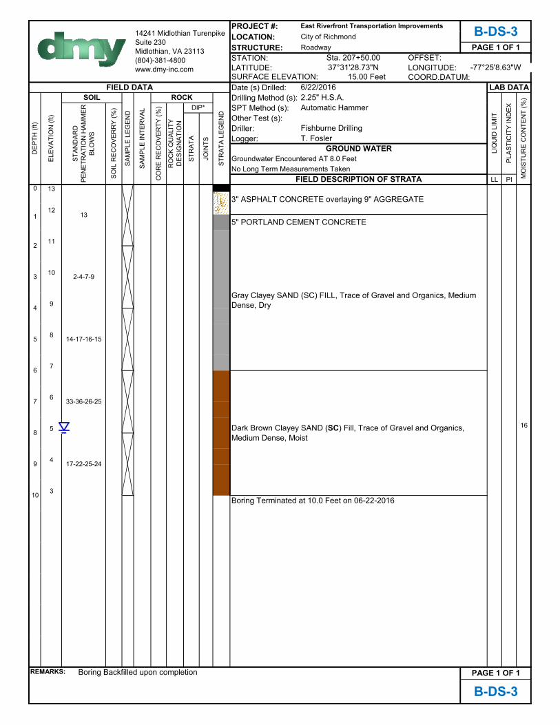
2.1 Field Explorations Fishburne Drilling, Inc., under subcontract to DMY, Inc., completed sixteen (16) soil borings in the field along the new alignment of the Dock Street, E. Main Street, and Nicholson Street segments. The soil borings were drilled at the project site employing split spoon sampling techniques per ASTM D 1586 using conventional hollow stem augers powered by an All-Terrain Vehicle (ATV) mounted drill rig. The soil sampling and penetration procedures were performed by driving a standard 1⅜-inch inside diameter, 2-inch outside diameter split spoon sampler with a 140-lb. automatic hammer falling from a height of 30 inches. The number of hammer blows required to drive the sampler 6 inches was recorded for a total of 18 inches. The penetration resistance value (N value) is the summation of the last two 6-inch increments. The standard penetration test N values are recorded on the boring logs. The results of the standard penetration tests indicate the comparative consistency of the cohesive soils and relative density of the cohesionless soils, and are used as an index to derive soil parameters from various empirical correlations. The soil samples obtained were visually classified by DMY using terms and descriptions in the Appendices. Selected samples were transported to a geotechnical laboratory for engineering testing. Table 2-1 lists the details of the boring locations and depths completed in the field.
2.2 Laboratory Testing
The soil samples obtained during the drilling operations were placed in labeled sample containers that were sealed to limit moisture loss. The DMY geotechnical engineer performed visual classification of the samples in accordance with ASTM D-2488 and the VDOT Manual of Instructions, using the Unified Soil Classification System (USCS). Representative samples were tested for the purpose of classification and index properties. The types of tests and related standards are listed in Table 2-2. The test results are summarized in Tables 2-3, 2-4, and 2-5. A detailed log of each boring, including laboratory test results, visual examination of the samples, and driller observations are provided in Appendix B of this report.
DMYGEO123015.10 4

FINAL GEOTECHNICAL ENGINEERING REPORT East Riverfront Transportation Improvement City of Richmond, Virginia
TABLE 2-1 Boring Details
Boring Number
Soil Boring Depth (feet) Station*
Boring Coordinates
Latitude (N) Longitude (W)
B-DS-1 10 203+50.0 37°31'32.81” -77°25'11.83” B-DS-2 10 205+50.0 37°31'30.37” -77°25'9.90 B-DS-3 10 207+50.0 37°31'28.73” -77°25'8.63” B-RW-1 20 206+85.0 37°31'28.96” -77°25'8.68” B-RW-2 15 209+10.0 37°31'27.02” -77°25'7.37” B-EM-1 10 14+00.0 37°31'27.92” -77°25'7.22” B-EM-2 10 15+50.0 37°31'27.02” -77°25'5.90” B-EM-3 10 18+10.0 37°31'25.27” -77°25'4.80” B-EM-4 10 20+20.0 37°31'23.88” -77°25'3.10” B-EM-5 10 22+80.0 37°31'21.46” -77°25'0.68” B-EM-6 10 24+85.0 37°31'19.17” -77°24'59.33” B-EM-7 10 27+50.0 37°31'17.34” -77°24'58.29” B-EM-8 10 29+20.0 37°31'14.79” -77°24'57.17” B-SP-1 30 301+75.0 37°31'13.41” -77°24'56.19” B-SP-2 30 31+85.0 37°31'12.99” -77°24'56.43” B-SP-3 30 31+70.0 37°31'12.81” -77°24'57.75
*The Station was estimated based on the existing site features.
TABLE 2-2 Laboratory Test Items and Related Standards
Type of Test Standard
Soil Natural Moisture Contents ASTM D2216
Atterberg Limits ASTM D4318
Sieve Analysis ASTM D422
Standard Proctor ASTM D698
California Bearing Ratio ASTM D1883
DMYGEO123015.10 5

FINAL GEOTECHNICAL ENGINEERING REPORT East Riverfront Transportation Improvement City of Richmond, Virginia
TABLE 2-3 Atterberg Limit Test Results
Boring No. Sample Depth Atterberg Limits Moisture
Content USC
S LL PL PI
B-DS-1 4.0’-10.0’ 52 26 26 25 CH
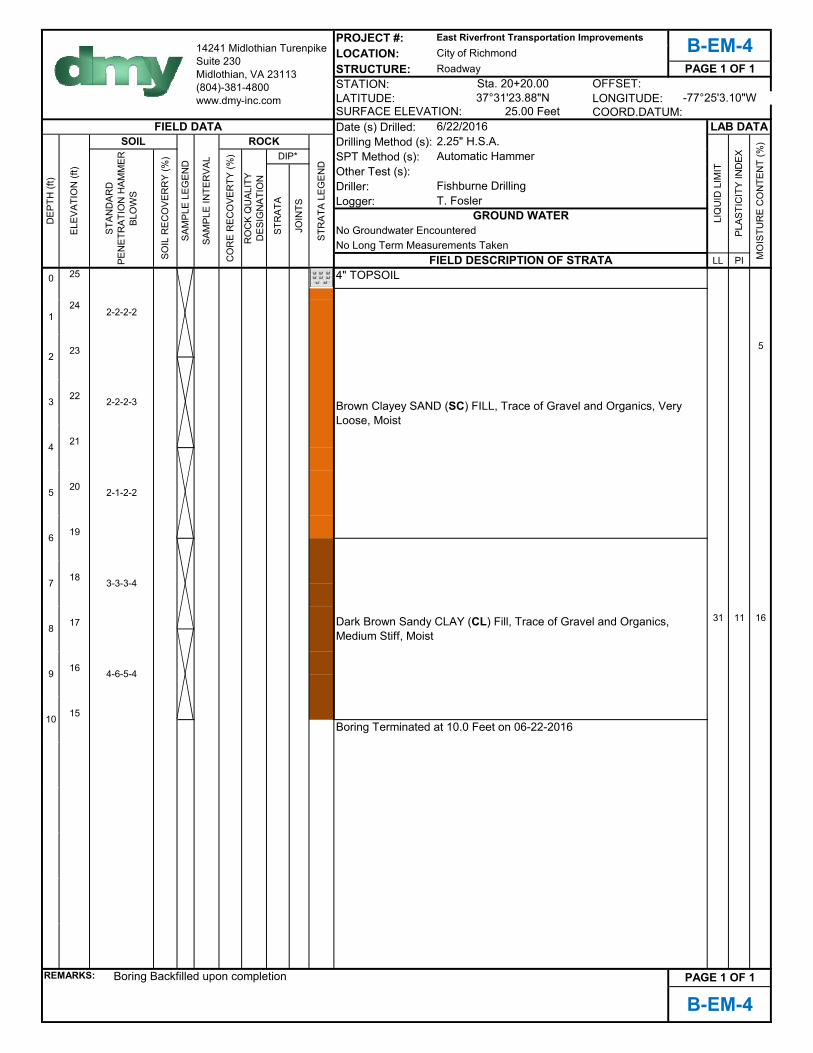
B-EM-4 6.0’-10.0’ 31 20 11 16 CL
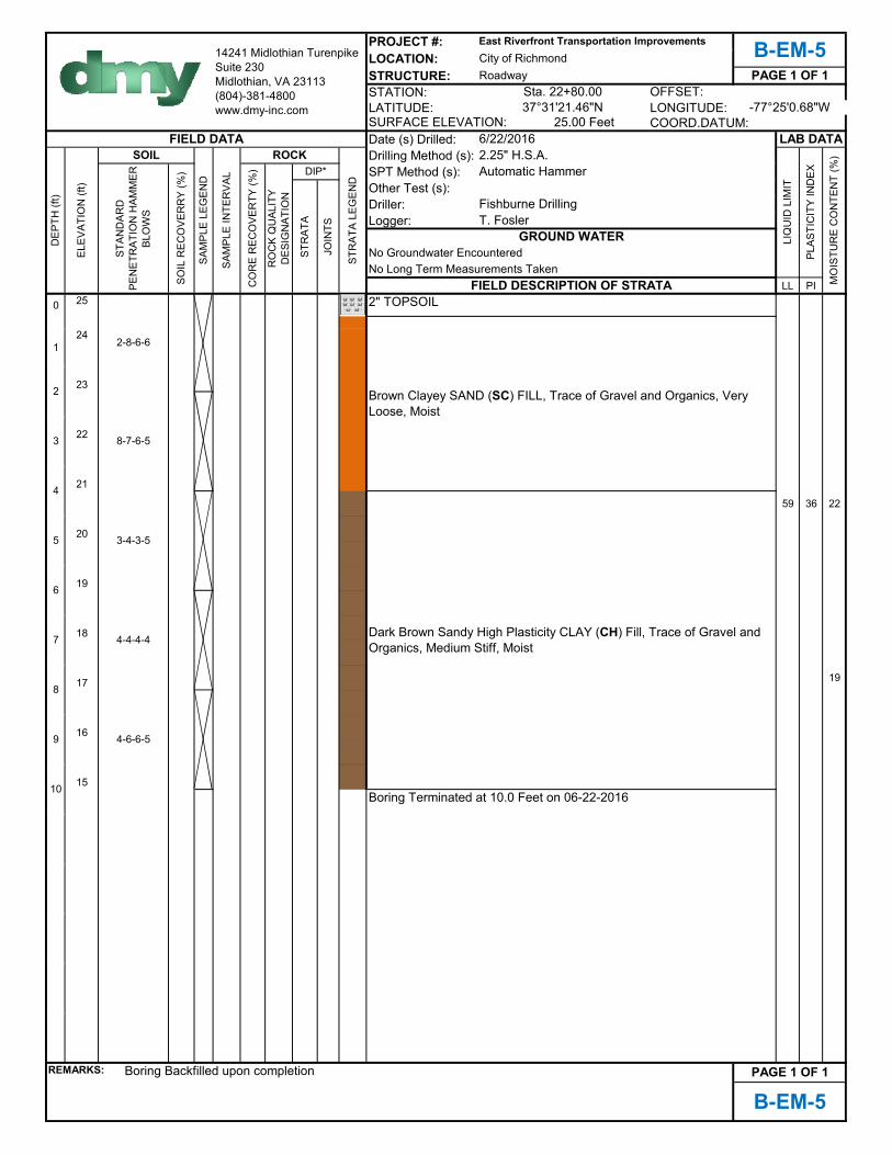
B-EM-5 4.0’-10.0’ 59 23 36 22 CH
B-SP-2 8.0’-13.0’ 25 16 9 16 CL
TABLE 2-4 Particle Size Analysis Test Results
Boring No. Sample Depth
Percent Passing Sieve Size (%) Moisture
Content USCS No.4 No.40 No.200
B-DS- 3 2.0’ 95.0 65.2 33.9 15.1 SC
B-RW-1 6.0’ 87.3 54.0 28.9 21.4 SC
B-RW-2 4.0’ 96.0 52.5 26.9 18.4 SM
B-SP-2 23.0’ 96.7 59.5 32.9 16.1 SC
TABLE 2-5 Proctor and CBR Test Results
Sample Location
Depth (ft) Description
Maximum Dry
Density (pcf)
Optimum Moisture Content
(%)
CBR (%)
Natural Moisture Content
(%)
B-EM-2 0.5-1.7
Brown Elastic Silt 95.8 22.8 3.4 22.0
DMYGEO123015.10 6
FINAL GEOTECHNICAL ENGINEERING REPORT East Riverfront Transportation Improvement City of Richmond, Virginia
Section 3
Subsurface Conditions 3.1 Regional Geology The Project site is located in the Coastal Plain Physiographic province within the extents of the Chesapeake Group Geologic Formation. This formation generally consists of alluvial soils classifying fine- to coarse-grained sand, silt, and clay. Portions of Dock and Main Streets are as close as 250 feet from the edge of the James River. The James River typically operates at a stage of Elev. 2 to 15 with major flooding at Elev. 22 or above. The Coastal Plain extends from the Fall Zone near Richmond (approximately one mile northwest of the project site) eastward to the Atlantic Ocean. Through the Fall Zone, the larger streams cascade to sea level off the resistant igneous and metamorphic rocks of the Piedmont Province to the west. The original site subsurface soils are no longer representative locally, especially within the upper 10 to 15 feet, due to the alteration during previous site development. Existing man-made fill can be quite variable in depth, composition and consistency, and the engineering properties of such material can be difficult to assess. 3.2 Soil Stratification The proposed roadway realignments for East Riverfront Transportation Improvements stretches over different soil profiles due to significant grade changes. The subsurface conditions encountered at the boring locations are shown on the test boring records in the appendices. These test boring records represent our interpretation of the subsurface conditions based on visual interpretation of field samples by a DMY geotechnical engineer and laboratory test results of the field samples. The lines designating the interfaces between various strata on the test boring records represent the approximate interface locations. The actual transitions between strata may be gradual, abrupt or slightly different depths. Dock Street Fishburne Drilling completed three (3) borings along the relocated Dock Street. The soils generally consisted of man-made fills to the boring terminus at 10 feet below the existing ground surface. The fills consisted of loose to medium dense gray clayey sand underlain by dark brown clayey sand or gray high-plasticity clay. The Standard Penetration Test (SPT) resistances generally ranged from 7 blows per foot (bpf) to 51 bpf. The moisture content ranged from 16 to 30 percent.
DMYGEO123015.10 7

FINAL GEOTECHNICAL ENGINEERING REPORT East Riverfront Transportation Improvement City of Richmond, Virginia East Main Street Fishburne Drilling completed eight (8) borings along the relocated East Main Street. The soils generally consisted of man-made fills to the boring terminus at 10 feet below the existing ground surface. The fills consisted of very loose to very dense brown clayey sand underlying brown sandy lean clay or dark brown high-plasticity clay. The SPT resistances generally ranged from 2 bpf to 22 bpf. The moisture content ranged from 5 to 34 percent. Retaining Wall Fishburne Drilling completed two (2) borings along the proposed retaining wall on the existing Dock Street. The soils generally consisted of man-made fills underlying alluvial sandy lean clay or silty sand to the boring terminus at 20 feet below the existing ground surface. The fills consisted very loose to very dense gray clayey sand and silty sand underlying light brown silty sand or brown clayey sand. The SPT resistances generally ranged from 2 bpf to over 50 bpf. The moisture content ranged from 5 to 18 percent. Signal Posts Fishburne Drilling completed three (3) borings were performed at each proposed signal post location. The soils generally consisted of man-made fills underlying gray alluvial silty sand or clayey sand to the boring terminus at 30 feet below the existing ground surface. The fills consisted of very loose to very dense brown silty sand or clayey sand underlying brown sandy lean or brown clayey sand. The SPT resistances generally ranged from 3 bpf to over 47 bpf. The moisture content ranged from 9 to 39 percent. 3.3 Groundwater Several borings completed for this study encountered groundwater. DMY judges this water to be perched water in the isolated soil stratum. The groundwater conditions observed, or lack thereof, reflect the conditions at the time of our exploration only. The highest groundwater levels are typically encountered in late winter and early spring. Fluctuations of the groundwater table should be expected to occur both seasonally and annually due to variations in rainfall, evaporation, transpiration, construction activity, and other site-specific factors.
DMYGEO123015.10 8

FINAL GEOTECHNICAL ENGINEERING REPORT East Riverfront Transportation Improvement City of Richmond, Virginia
Section 4 Engineering Recommendations
4.1 General The following conclusions and recommendations are based on the previously discussed project information, observations at the site, analysis of the laboratory results, interpretation of the field data obtained during the investigation and our experience with similar subsurface conditions. They are subject to the limitations set forth in Section 6 below. If the proposed construction scheme varies from that described, DMY requests the opportunity to review these recommendations. 4.2 Pavement Design 4.2.1 General We understand that some portion of the new roadway will be constructed on the existing roadway subgrade. Based on the field exploration and laboratory test results, the existing roadway subgrade was in fair condition and appears suitable to support the new pavement. Where new pavement subgrade is required, it should be suitably compacted and prepared using VDOT criteria for the roadway earthwork activities. Site work activities undertaken during the wetter portion of the year could require soil modification or stabilization to establish a proper subgrade for new fills and pavement base if aeration and drying are not permitted by seasonal weather conditions. Depending on the construction schedule, lime, cement, or other forms of soil modification or stabilization, including undercut and replacement with suitable subbase should be considered. DMY obtained design criteria from the Guidelines for 1993 AASHTO Pavement Design prepared by VDOT Materials Division. DMY developed design ESAL using the traffic data provided by WRA. Table 4-1 and 4-2 summarize DMY’s design ESAL calculations. Based on the field exploration results and laboratory testing results for the soil sample collected from the existing East Main Street, DMY adopted a California Bearing Ratio of 3.8 for the pavement design. Please note that if borrow materials are needed for the pavement subgrade, a minimum CBR value of 4.0 is required.
TABLE 4-1 Summary of the Pavement Design Parameters
Initial Serviceability
Terminal Serviceability Reliability Standard
Deviation
4.2 2.8 85% 0.49
DMYGEO123015.10 9
FINAL GEOTECHNICAL ENGINEERING REPORT East Riverfront Transportation Improvement City of Richmond, Virginia
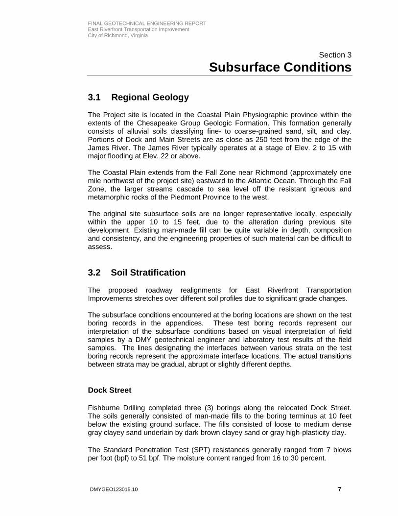
TABLE 4-2 General Traffic Data Inputs for Pavement Design
Pavement Design Life (Undivided Primary) 20 years
Current ADT (East Main/Dock Street) 8008/9268
ESAL Factor for Trailer Trucks 1.05
ESAL Factor for Single Unit Trucks 0.46
ESAL Factor for Passenger Cars 0.0002
Percent Trailer Trucks 1.0%
Percent Single Unit Trucks 2.0%
Percent Passenger Cars 97%
ESALs (East Main/Dock Street) 916,299/1,060,472
4.2.2 Pavement Section To meet the required structural number, DMY considered several combined pavement sections for the design. It is our opinion that an intermediate asphalt layer be incorporated into the design to facilitate the possible staged construction. Based on the design parameters and traffic data provided, considering the minimum layer thickness required by VDOT, DMY recommends the following pavement section for the relocated Dock Street and East Main Street new roadway:
Surface: 2.0” (220 lbs./S.Y.) Asphalt Concrete, Type SM-12.5D Intermediate: 2.0” (220 lbs./S.Y.) Asphalt Concrete, Type IM-19.0D Bituminous Base: 4.0” Asphalt Concrete, Type BM-25.0A Aggregate Subbase: 10.0” Aggregate Base Material, Type I, No. 21-B
Please note that Standard UD-2 underdrains and outlets are required on all raised medians. The aggregate base material (Type I, Size #21-B) should be connected to a longitudinal pavement drain (UD-4) with outlets or day lighted (to the face of the ditch) to provide for positive lateral drainage 4.3 Retaining Wall The relocated Dock Street will require significant roadway fill to establish grade match to the new roundabout construction.
DMYGEO123015.10 10

FINAL GEOTECHNICAL ENGINEERING REPORT East Riverfront Transportation Improvement City of Richmond, Virginia Based on the latest conceptual design plan provided to us, the highest fill section will be located at approximately Station 208+10 on the relocated Dock Street, where over 25 feet of fill is required. Based on the field exploration and our understanding of the project, we recommend that Mechanical Stabilized Earth (MSE) wall be considered for the design. The amount of pressure exerted by backfill on the retaining walls depends upon the height of the wall, drainage provisions, type of backfill, and method of placing the backfill. The backfill should be compacted in accordance with VDOT specifications. It is also recommended that the granular backfill be placed with a restricted tamping and compacting. In placing the backfill material, no heavy vibratory roller should pass within five (5) feet of back of the wall. Excessive tamping or compacting the granular backfill in thin layers will increase the lateral earth pressure. Within 5-feet of the wall, hand operated equipment such as a vibratory plate or walk behind roller should be used to compact the fill. In general, the loosely placed lift thickness for a granular backfill may be no greater than eight (8) inches. However, lift thickness for the hand-operated equipment should not exceed six (6) inches to promote suitable compaction. Lateral earth pressure coefficients for active, at rest and passive conditions and equivalent fluid pressure for active condition were estimated for recommended backfill materials. DMY also recommends following earth pressure coefficients be considered:
Friction angle φ = 30° Total unit weight γ = 135 pcf Active condition: Ka = 0.34 Equivalent fluid pressure: Gh = 46 pcf (active condition) Passive condition: Kp = 3.00 Coefficients of sliding: f = 0.36
These parameters do not include local or uniform surcharge loads which should be applied along top of walls that support sidewalks, pavements, or other loading conditions not typically included in standard wall design calculations. We understand that WRA will be responsible for the wall design. The wall should be designed in accordance with AASHTO LRFD (2014) 4.4 Signal Post Foundation Based on the soils encountered in the field, DMY recommends that drilled shafts be designed to support the signal posts. Table 4-3 lists the recommended bearing capacity related to the shaft size and tip elevations.
DMYGEO123015.10 11

FINAL GEOTECHNICAL ENGINEERING REPORT East Riverfront Transportation Improvement City of Richmond, Virginia
TABLE 4-3 Drilled Shaft Foundation for Signal Posts
Signal Post Location Drilled Shaft
Diameter
Approximate Tip
Elevation Bearing Capacity
(kips)
NW of E. Main and Nicholson
42”
EL 10.0 80
NE of E. Main and Nicholson EL 10.0 85
SE of E. Main and Nicholson EL 6.0 95
4.5 Seismic Conditions For seismic design, the subsurface condition at this site can be classified as Site Class E as determined using SPT N-values (AASHTO LRFD Bridge Design Specifications, 7th Edition, 2014). Various seismic design parameters for the site are presented in Table 4-4 below.
TABLE 4-4 Recommended AASHTO Seismic Design Parameters
AASHTO Seismic Design Parameter Value AASHTO Code Reference
Site Class E Table 3.10.3.1-1
Seismic Zone 1 Table 3.10.6.1. Tables 3.10.3.2-3, & Equation 3.10.4.2-6
Peak Ground Acceleration Coefficient. (PGA) 0.035 Figure 3.10.2.1-1
Spectral Acceleration Coefficient 0.2 sec (S2) 0.09 Figure 3.10.2.1-2
Spectral Acceleration Coefficient 1.0 sec (S1) 0.035 Figure 3.10.2.1-3
DMYGEO123015.10 12

FINAL GEOTECHNICAL ENGINEERING REPORT East Riverfront Transportation Improvement City of Richmond, Virginia
Section 5
Construction Considerations For the proposed new pavement subgrade, once the existing pavement structures, topsoil, and any other unsuitable soils are removed, the Geotechnical Engineer should observe the exposed subgrade soils. The exposed soils should be compared with those encountered in the soil test borings. Significant differences should be brought to the attention of the engineer for the appropriate recommendations. Prior to the placement of the embankment fill, the exposed subgrade soil should be proof-rolled. Proof rolling should be performed to determine if soft zones or unsuitable soils are present to provide a suitable base for placement of fill. We recommend a rubber-tired, fully loaded, tandem-axle dump truck with a fully loaded weight greater than 25 tons to be used for performing proof-rolling operations. Fill soils should be placed in maximum 8-inch-thick loose lifts and compacted to at least 95 percent of maximum dry soil unit weight as determined by the laboratory compaction test (VTM-1). The upper 6 inches of pavement subgrade should be compacted to a minimum of 100 percent of the maximum dry unit weight. Soil moisture during placement should be maintained within VDOT’s Specifications of ±2 percentage points of the optimum moisture content determined from the laboratory compaction tests. Any unsuitable soils undercut within 1 feet of the final pavement subgrade elevation should be replaced with VDOT select material Type I (minimum CBR of 30). Where fill materials will be placed to widen existing fills, or placed against sloping ground, the contractor must scarify the existing soil subgrade. New fill must be benched or keyed into the existing material (see VDOT Road and Bridge Specification Section 303.04(h)). In confined areas, such as utility trenches, portable compaction equipment and thin lifts of 3 to 4 inches will likely be required to achieve the specified degrees of compaction. Based on the results of moisture content testing during construction, some soils within the project limits may require additional working or treatment (drying, modification/stabilization) in event of rainy periods. However, we recommend that the contractor have equipment on site during earthwork for both wetting and drying fill soils as the soil moisture levels can significantly change during earthwork operations. The moisture content of clays and silts is difficult to adjust (when compared to sands) for the purposes of obtaining proper compaction. Additionally, the nature of a confined space such as culvert excavation typically limits compaction techniques to hand-operated equipment, whose dynamic action is usually adequate for densifying sands but may not be adequate to place clays and silts. For signal post drilled shaft construction, the bottom of the drilled shaft excavation must be flat; steps in the bearing surface, or a sloping bearing surface, are not acceptable. The drilled shaft excavation must be thoroughly cleaned of loose sand, clay and silt. Cleanout may be performed by a cleanout bucket, or other methods acceptable to the Engineer. Final bottom should be inspected. At the time of concrete placement, a minimum of 50 percent of the base of the shaft should have
DMYGEO123015.10 13
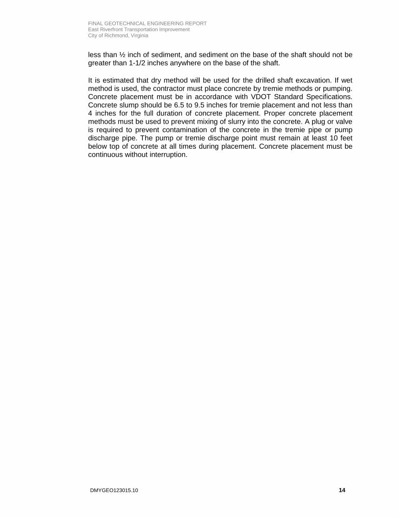
FINAL GEOTECHNICAL ENGINEERING REPORT East Riverfront Transportation Improvement City of Richmond, Virginia less than ½ inch of sediment, and sediment on the base of the shaft should not be greater than 1-1/2 inches anywhere on the base of the shaft. It is estimated that dry method will be used for the drilled shaft excavation. If wet method is used, the contractor must place concrete by tremie methods or pumping. Concrete placement must be in accordance with VDOT Standard Specifications. Concrete slump should be 6.5 to 9.5 inches for tremie placement and not less than 4 inches for the full duration of concrete placement. Proper concrete placement methods must be used to prevent mixing of slurry into the concrete. A plug or valve is required to prevent contamination of the concrete in the tremie pipe or pump discharge pipe. The pump or tremie discharge point must remain at least 10 feet below top of concrete at all times during placement. Concrete placement must be continuous without interruption.
DMYGEO123015.10 14

FINAL GEOTECHNICAL ENGINEERING REPORT East Riverfront Transportation Improvement City of Richmond, Virginia
Section 6
Limitations of Liability
This report has been prepared for the exclusive use of Whitman, Requardt & Associates, LLP (WRA) , City of Richmond, VDOT, and other team members for the project. Our conclusions and recommendations have been rendered in a manner consistent with the level of care and skill ordinarily exercised by members of the geotechnical engineering profession in the Commonwealth of Virginia at the time of our study. We make no other warranty, express or implied. Conclusions and recommendations presented in this report are based upon the available soil information, currently accepted engineering principles, and design details furnished by the client. DMY should be notified of any revisions to the scope of this project so that these revisions may be evaluated against the subsurface conditions. DMY will submit a written supplementary report to confirm the recommendations contained herein or to address changes to our recommendations. The soils encountered in the borings varied between boring locations. Other discontinuity in soil type and geology may exist, including abrupt strata changes and soil strength variations. The extent of these variations may not be fully determined from the borings or site reconnaissance. Additional variations may not become apparent until mass excavation commences. It is recommended that the owner retain the services of the DMY to observe the construction.
DMYGEO123015.10 15

East Riverfront Transportation Improvements
City of Richmond, Virginia Figure 1
Project Site Vicinity Map
DMY Project No. GEO 123015.10
Project Site

Brick Paver
Sidewalk
C/L Creek
270'
R276'
R
= POT 100+00.00 PEEBLES ST.= POT 209+33.90 DOCK ST.PT 14+82.84 MAIN ST.
R
BL: XX NW, NE, SW, SE
GD
15"
"
"
"
"
"
"
"
"
"
T/Tg
6"W
CATV
10"SFM
2"G
E
12"SAN.
MH
/ /
"
"
"
"
"
"
"
"
"
MH
EP
"
"
"
"
"
"
"
"
E
GV
T
"
"
"
"EXISTING SIDEWALK
"
"
"
"
"
WM
WV
LP
"
SU
RV
EY
ED
BY: ..
CIT
Y
OF
RIC
HM
ON
D..
Curb & Gutter
Sidewalk
Basin
Sewer Manhole
Storm Sewer
Sanitary Sewer
Sanitary Sewer (Gravity)
Electric Line
Gas Line
Telephone/Telegraph
TV Cable
Water Line
Tree / Exist. Tree To Be Removed / Stump
Property Line Asphalt
Curb & Gutter
Basin
Manhole
Proposed Sewer
Utility Pole
Property Pin
Cornerstone
Fence
Edge of Pavement
Fire Hydrant
Alley Crossing/Driveway
Coping
Existing Curb Cut Ramp
-:LEGEND:-Proposed Conc. Sidewalk
Brick Sidewalk
Water ValveCastings:
Water Meter
Gas Valve
Gas Drip
Telephone Manhole
Electric Manhole
Proposed Curb Cut Ramp
Decorative Light
Conduit
Conduit (Conc. Encased)
Retaining Wall
(Force Main)
Technical Administrative
Surveys Superintendent
Project Engineer
Maintenance Engineer
City Traffic Engineer Director of Public Works
Transportation / Public Works
Deputy Director for
Capital Project Administrator
CHECKED BY:
REVIEWED BY FIELD NOTES SCALE DATE SHEET DRAWING NO.REFERENCES REVISIONS
1. Lot dimensions in parentheses are from deed.
20 ,2. Property owners correct as of
3. Ordinance Number
4. Adopted
5. Accepted
NOTES Existing Curb
DEPARTMENT OF PUBLIC WORKS
RICHMOND, VIRGINIA 0-28708
CIP:XXX-XXX-XXXX
APRIL 2016
EAST RIVERFRONT TRANSPORTATION IMPROVEMENT
DESIGN BY:
DRAWN BY:
SU
PE
RVIS
ED
BY:
DESCRIPTIONPROPOSEDEXISTING
ROADWAY LIGHTING LEGEND
J
E
CONDUIT RUN IDENTIFIER
JUNCTION BOX
CONDUIT
DECORATIVE LUMINAIRE ON ALUMINUM POLE IN BLACK COLOR)
DECORATIVE LIGHT POLE AND LUMINAIRE (RICHMOND LANTERN
UTILITY POLE
CONVENTIONAL ROADWAY LUMINAIRE AND BRACKET ARM ON
THESE PLANS ARE UNFINISHED
AND UNAPPROVED AND ARE NOT
TO BE USED FOR ANY TYPE
OF CONSTRUCTION OR THE
ACQUISITION OF RIGHT OF WAY.
NOT TO SCALE 10(1)
LIGHTING
GENERAL NOTES - LIGHTING
2"
L
REFERENCED
CONSTRUCTION BASELINESTATION, OFFSET
STATION AND POLE TYPE IDENTIFIER
(N/A FOR DECORATIVE POLES)
POLE STANDARD
LP-1, BW
___________ CONST. B
STA. 123+45.6, 78.9' LEFT
(N/A FOR DECORATIVE POLES)
BW=BREAKAWAY, NBW=NON-BREAKAWAY
2" -EMPTYFOR ROADWAY LIGHTING
INDICATES PROPOSED CONDUIT
MOUNTING HEIGHT
POLE NUMBER
LUMINAIRE IDENTIFIER
LIGHT POLES)
FOR DECORATIVE
(NOT APPLICABLE
ARM LENGTH
LUMINAIRE WATTAGE
XX - 250W - XX'xXX'
E. CARY S
TREET PE
AR
ST
RE
ET
DOCK STREET
DOCK STREET
E. M
AIN STREET
PEEBLES
STREET
E. MAIN STREET
E. MAIN STREET
E. MAIN STREET
NIC
HOLS
ON ST
RE
ET
30% PLANS
LIGHTING PLAN
INDICATES EXISTING STREET LIGHT TO BE REMOVEDR
E INDICATES EXISTING STREET LIGHT TO REMAIN
WORKS AND DEPARTMENT OF PUBLIC UTILITIES.
REMOVAL. THE CONTRACTOR SHALL COORDINATE REMOVAL WITH THE CITY OF RICHMOND DEPARTMENT OF PUBLIC THE CONTRACTOR SHALL REMOVE THE EXISTING LUMINAIRES, BRACKET ARMS AND UTILITY POLES DESIGNATED FOR
LOCATIONS WHERE PROPOSED CONDUIT WILL CROSS CONDUIT DESIGNATED TO BE ABANDONED.OR THE CONTENTS THEREOF. THESE CONDITIONS SHALL APPLY AT ALL SUCH CONDUIT CROSSINGS EXCEPT THOSE HAND-DIG THE TRENCH AND SHALL TAKE ADEQUATE CARE NOT TO DAMAGE THE EXISTING CONDUIT, UTILITY LINE AT LOCATIONS WHERE PROPOSED CONDUIT CROSSES EXISTING CONDUIT OR UTILITIES THE CONTRACTOR SHALL
STRENGTH.
NOTED ON PLANS. ALL CONDUITS SHALL BE FURNISHED WITH A PULL STRING WITH A 500 POUND MINIMUM PULL PLANS. ALL UNDERGROUND CONDUITS SHALL BE SCHEDULE 40, RIGID POLYVINYL CHLORIDE UNLESS OTHERWISE ALL UNDERGROUND CONDUITS SHALL BE INSTALLED IN ACCORDANCE WITH STD. ECI-1 UNLESS OTHERWISE NOTED ON
INLETS, MANHOLES, AND OTHER OBSTRUCTIONS.
CONDUITS SHALL BE INSTALLED WITH THE LARGE RADIUS OFFSETS (5' MINIMUM RADIUS) TO BYPASS DRAINAGE
LOCATING ALL EXISTING UTILITIES AND LIGHTING SYSTEMS BEFORE PROCEEDING WITH THE WORK.SHOWN ARE NOT GUARANTEED TO BE COMPLETE OR ACCURATELY LOCATED. THE CONTRACTOR IS RESPONSIBLE FOR CERTAIN UTILITIES WITHIN THE VICINITY OF THIS CONTRACT AREA ARE SHOWN ON THE PLANS. THE UTILITIES
ALL JUNCTION BOXES SHALL BE PROVIDED WITH A MEANS FOR DRAINAGE.
TO INSTALLATION.
THE LOCATIONS OF ALL EQUIPMENT SHALL BE STAKED OUT IN THE FIELD AND APPROVED BY THE ENGINEER PRIOR
GROUND RODS SHALL BE INSTALLED AT ALL POLE FOUNDATIONS AND JUNCTION BOXES.
CONDITIONS.
CONDUITS SHOWN ON THESE PLANS ARE DIAGRAMMATIC AND ACTUAL CONDUIT RUNS SHALL CONFORM TO THE FIELD
MASTER CIRCUITS THAT THE CITY OF RICHMOND DPU WILL PROVIDE TO EACH LIGHT POLE.
LUMINAIRES SHALL NOT REQUIRE A PHOTOCELL OR PHOTOEYE CONTROL. PHOTOCONTROL IS PRESENT ON THE
NOTICE SHALL BE GIVEN PRIOR TO NEEDING INSPECTION.
CONDUITS PRIOR TO TRENCHES BEING CLOSED OR ENCASEMENT CONCRETE BEING POURED. AT LEAST TWO WEEKS THE CONTRACTOR SHALL CONTACT ROBERT PARHAM WITH THE CITY OF RICHMOND AT 804-363-3437 TO INSPECT
COMPLETION OF LIGHT POLE AND LUMINAIRE INSTALLATION.
804-646-7000 TO ENERGIZE THE LIGHT POLES. AT LEAST 4 WEEKS NOTICE SHALL BE GIVEN PRIOR TO THE CONTRACTOR SHALL CONTACT BRIAN CULVER WITH THE CITY OF RICHMOND DPU STREET LIGHT SECTION AT
POLES AFTER INSTALLATION BY THE CONTRACTOR.
PUBLIC UTILITIES (DPU) STREET LIGHT SECTION WILL INSTALL ALL ELECTRICAL WIRING AND ENERGIZE LIGHT CONCRETE ENCASEMENT, JUNCTION BOXES, LIGHT POLES AND LUMNAIRES. THE CITY OF RICHMOND DEPARTMENT OF THE CONTRACTOR SHALL BE RESPONSIBLE FOR THE INSTALLATION OF ALL LIGHT POLE FOUNDATIONS, CONDUITS,
13.
12.
11.
10.
9.
8.
7.
6.
5.
4.
3.
2.
1.
TRAFFIC ENGINEER
Baltimore, Maryland
Whitman, Requardt & Associates
10(3)
10(4)
10(5)
10(6)
10(7)
10(8)
JDC
JDC
KWF
B-SP-1
B-SP-2
B-SP-3
B-EM-8
BORING LOCATION PLAN
B-DS-1 B-DS-2 B-DS-3
B-EM-1
B-EM-2 B-EM-3
B-EM-4 B-EM-5B-EM-6
B-EM-7
B-RW-1
Note:
Boring Location (16 Total)
B- Boring Number
B-RW-2
John-PC
Soil Boring
John-PC
Soil Boring
John-PC
Soil Boring
John-PC
Soil Boring
John-PC
Soil Boring
John-PC
Soil Boring
John-PC
Soil Boring
John-PC
Soil Boring
John-PC
Soil Boring
John-PC
Soil Boring
John-PC
Soil Boring
John-PC
Soil Boring
John-PC
Soil Boring
John-PC
Soil Boring
John-PC
Soil Boring
John-PC
Soil Boring
John-PC
Soil Boring
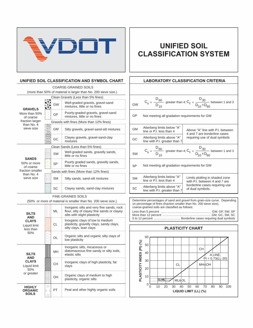
UNIFIED SOIL CLASSIFICATION AND SYMBOL CHART LABORATORY CLASSIFICATION CRITERIA
PLASTICITY CHART
COARSE-GRAINED SOILS
FINE-GRAINED SOILS
(more than 50% of material is larger than No. 200 sieve size.)
(50% or more of material is smaller than No. 200 sieve size.)
Well-graded gravels, gravel-sandmixtures, little or no fines
greater than 4;
greater than 4;
between 1 and 3
between 1 and 3
=
=
=
=
Clean Gravels (Less than 5% fines)
C
C
C
C
D
D
D
D
D
D
D
D
D
D
u
u
c
c
60
60
30
30
x
x
10
10
10
10
60
60
Clean Sands (Less than 5% fines)
Above "A" line with P.I. between4 and 7 are borderline casesrequiring use of dual symbols
Limits plotting in shaded zonewith P.I. between 4 and 7 areborderline cases requiring useof dual symbols.
Determine percentages of sand and gravel from grain-size curve. Dependingon percentage of fines (fraction smaller than No. 200 sieve size),coarse-grained soils are classified as follows:
Less than 5 percentMore than 12 percent5 to 12 percent
GW, GP, SW, SPGM, GC, SM, SC
Borderline cases requiring dual symbols
Gravels with fines (More than 12% fines)
Sands with fines (More than 12% fines)
Well-graded sands, gravelly sands,little or no fines
Silty gravels, gravel-sand-silt mixturesAtterberg limits below "A"line or P.I. less than 4
Atterberg limits below "A"line or P.I. less than 4
Atterberg limits above "A"line with P.I. greater than 7
Atterberg limits above "A"line with P.I. greater than 7
Silty sands, sand-silt mixtures
Inorganic silts and very fine sands, rockflour, silty of clayey fine sands or clayeysilts with slight plasticity
Inorganic clays of low to mediumplasticity, gravelly clays, sandy clays,silty clays, lean clays
Inorganic silts, micaceous ordiatomaceous fine sandy or silty soils,elastic silts
Peat and other highly organic soils
Poorly-graded gravels, gravel-sandmixtures, little or no fines Not meeting all gradation requirements for GW
Not meeting all gradation requirements for GWPoorly graded sands, gravelly sands,little or no fines
Clayey gravels, gravel-sand-claymixtures
Clayey sands, sand-clay mixtures
Inorganic clays of high plasticity, fatclays
Organic silts and organic silty clays oflow plasticity
Organic clays of medium to highplasticity, organic silts
60
50
40
30
20
10
00 10 20 30 40 50
LIQUID LIMIT (LL) (%)
CL
CL+ML
CH
PL
AS
TIC
ITY
IND
EX
(P
I) (
%)
60 70 80 90 100
GW GW
GRAVELS
SANDS
SILTSAND
CLAYS
SILTSAND
CLAYS
HIGHLYORGANIC
SOILS
More than 50%of coarse
fraction largerthan No. 4sieve size
50% or moreof coarse
fraction smallerthan No. 4sieve size
Liquid limitless than
50%
Liquid limit50%
or greater
SW SW
GM GM
SM SM
ML
MH
PT
GP GP
SPSP
GC GC
SC SC
CL
CH
OL
OH
MH&OH
A LINE:PI = 0.73(LL-20)
ML&OL
UNIFIED SOILCLASSIFICATION SYSTEM
CH -
Fat Clay
CL -
Lean Clay
FL -Fill
GC - Clayey
Gravel
GM - Silty
Gravel
GP - Poorly-
graded Gravel
GW - Well-
Graded Gravel
ML - Silt
SC -
Clayey Sand
CL-ML
GC-GM
SW - Well-
Graded Sand
SM - Silty
Sand
SP - Poorly-
Graded Sand
Pavement/Soils
ASPH-
ASPHALT PVT
CONC-
CONCRETE PVT
GP-GC
GP-GM
GW-GC
GW-GM
SP-SC
SP-SM
SW-SC
SW-SM
AND -
Andesite
BST -
Basalt
CAV -
Cavity
DBS -
Diabase
DRT -
Diorite
GBR -
Gabbro
GGE -
Gouge SPT
Core
Grab
No
Recovery
Other
SLS -
Siltstone
SST-SHL -
Interbedded
Sandstone/Shale
MYL -
Mylonite
PHY -
Phyllite
RHY -
Rhyolite
SCH -
Schist
SedimentaryRocks
MetamorphicRocks
SamplingIgneousRocks
MATERIAL AND SAMPLESYMBOLS LIST
GNS -
Gneiss
Auger
Undisturbed
CGL -
Conglomorate
COL -
Coal
GWK -
Graywacke
LST -
Limestone
SHL -
Shale
SST -
Sandstone
CLST - Cherty
Limestone
SLT -
Slate
GRD -
Granodiorite
GRN
Granite
POR -
Porphyry
SE -
Shell Bed
UCY -
Underclay
SST-SLS -
Interbedded
Sandstone/Siltstone
MH -
Elastic Silt
MH/CH
MH/ML
MH/SM
ML/CL
ML/GM
ML/SM
GM/GP
GM/ML
GM/SM
HWR
Highly Weathered
Rock
MST
Mudstone
BRC -
Breccia
Misc.
SHDS
Shaly Dolostone
CHK
Chalk
SHLS-Shaly
Limestone
MSH
Silty Shale
Page 1of 2
SSHL
Sandy Shale
Vane

Pavement/SoilsSedimentary
RocksMetamorphic
RocksSampling
IgneousRocks
MATERIAL AND SAMPLESYMBOLS LIST
TOPS-
TOPSOIL CH/CL CH/MH CH/SC
CL/ML CL/SC CL/CHCRA
Crushed Aggregate
GC/SC
GP/GW
GP/SPGW/GP ML/MH
OH
Organic
OH/OL
OL
OrganicOL/OHPT
Peat
SC/CH
SC/CL
SC/GC SC-SM
BLD-Boulder
Bed
CHT
Charnocktite
DLS
Dolostone
LST-DLS-
Interbedded
Limestone/Dolostone
MSLS
Metasiltstone
MSST
Metasandstone
QZT -
Quartzite
MBST
Metabasalt
SPS
Soapstone
MBL
Marble
Page 2 of 2
SP/SW SM/GM SM/MH
SM/ML SM/SC SP/GP SW/SP
CHRT

PROJECT #:LOCATION:STRUCTURE:STATION:LATITUDE: LONGITUDE:
Date (s) Drilled:Drilling Method (s):SPT Method (s):Other Test (s):Driller:Logger:
LL PI
0 17
2716
15
14
13
30
12
11
10
9
8 52 26 25
7
REMARKS:
Roadway
LAB DATASURFACE ELEVATION:
LIQ
UID
LIM
IT
T. Fosler
PAGE 1 OF 1
PLAS
TIC
ITY
IND
EX
MO
ISTU
RE
CO
NTE
NT
(%)
37°31'32.81"NCOORD.DATUM:
OFFSET:Sta. 203+50.00-77°25'11.83"W
17.00 Feet
DIP*
5
3
7
B-DS-1
Boring Backfilled upon completion
5-4-5-2
Dark Gray Clayey SAND (SC) FILL, Trace of Gravel and Organics, Loose, Wet
Gray High- Plasticity Sandy CLAY (CH) FILL, Trace of Gravel, Medium Stiff, Wet
9-5-4-3
2
3-4-10-71
9
10
4" TOPSOIL
Boring Terminated at 10.0 Feet on 06-22-2016
Gray High- Plasticity Sandy CLAY (CH) FILL, Trace of Gravel, Medium Stiff, Wet
6
11-4-3-6
4
5-3-4-4
Dark Gray Clayey SAND (SC) FILL, Trace of Gravel and Organics, Loose to Medium Dense, Moist
PAGE 1 OF 1
8
14241 Midlothian Turenpike Suite 230Midlothian, VA 23113(804)-381-4800 www.dmy-inc.com
ROCK
East Riverfront Transportation ImprovementsB-DS-1City of Richmond
SAM
PLE
LEG
END
SOIL
REC
OVE
RR
Y (%
)
SAM
PLE
INTE
RVA
L
STR
ATA
LEG
END
JOIN
TS
GROUND WATERGroundwater Encountered Encountered at 5.5 Feet
Automatic Hammer2.25" H.S.A.
FIELD DATA
DEP
TH (f
t)
CO
RE
REC
OVE
RTY
(%)
RO
CK
QU
ALIT
Y D
ESIG
NAT
ION
6/22/2016
No Long Term Measurements TakenFIELD DESCRIPTION OF STRATA
STAN
DAR
D
PEN
ETR
ATIO
N H
AMM
ER
BLO
WS
ELEV
ATIO
N (f
t)
SOIL
Fishburne Drilling
STR
ATA

PROJECT #:LOCATION:STRUCTURE:STATION:LATITUDE: LONGITUDE:
Date (s) Drilled:Drilling Method (s):SPT Method (s):Other Test (s):Driller:Logger:
LL PI0 15
14
13
12
11 22
10
9
8
7
6
5
REMARKS:
LAB DATASURFACE ELEVATION:
LIQ
UID
LIM
IT
T. Fosler
PAGE 1 OF 1
PLAS
TIC
ITY
IND
EX
MO
ISTU
RE
CO
NTE
NT
(%)
37°31'30.37"NCOORD.DATUM:
OFFSET:Sta. 205+50.00-77°25'9.90"W
15.00 Feet6/22/2016
5
3
7
Roadway
9
10
No Long Term Measurements TakenFIELD DESCRIPTION OF STRATA
STAN
DAR
D
PEN
ETR
ATIO
N H
AMM
ER
BLO
WS
12-91
4" ASPHALT CONCRETE overlaying 8" AGGREGATE
Gray Clayey SAND (SC) FILL, Trace of Gravel and Organics, Medium Dense, Dry
8
ELEV
ATIO
N (f
t)
4-5-5-7
2
SOIL
6
4-4-8-8
4
B-DS-2
Boring Backfilled upon completion
11-10-10-9
PAGE 1 OF 1
Boring Terminated at 10.0 Feet on 06-22-2016
Dark Brown Clayey SAND (SC) Fill, Trace of Gravel and Organics, Medium Dense, Moist
9-9-10-10
14241 Midlothian Turenpike Suite 230Midlothian, VA 23113(804)-381-4800 www.dmy-inc.com
ROCK
East Riverfront Transportation ImprovementsB-DS-2City of Richmond
SAM
PLE
LEG
END
SOIL
REC
OVE
RR
Y (%
)
SAM
PLE
INTE
RVA
L
STR
ATA
LEG
END
JOIN
TS
GROUND WATERNo Groundwater Encountered
Automatic Hammer2.25" H.S.A.
FIELD DATA
Fishburne Drilling
STR
ATA
DEP
TH (f
t)
CO
RE
REC
OVE
RTY
(%)
RO
CK
QU
ALIT
Y D
ESIG
NAT
ION
DIP*
PROJECT #:LOCATION:STRUCTURE:STATION:LATITUDE: LONGITUDE:
Date (s) Drilled:Drilling Method (s):SPT Method (s):Other Test (s):Driller:Logger:
LL PI0 13
12
11
10
9
8
7
6
5 16
4
3
REMARKS:
6/22/2016
2-4-7-9
2
SOIL
Fishburne Drilling
STR
ATA
DEP
TH (f
t)
CO
RE
REC
OVE
RTY
(%)
RO
CK
QU
ALIT
Y D
ESIG
NAT
ION
14241 Midlothian Turenpike Suite 230Midlothian, VA 23113(804)-381-4800 www.dmy-inc.com
ROCK
East Riverfront Transportation ImprovementsB-DS-3City of Richmond
SAM
PLE
LEG
END
SOIL
REC
OVE
RR
Y (%
)
SAM
PLE
INTE
RVA
L
STR
ATA
LEG
END
JOIN
TS
GROUND WATERGroundwater Encountered AT 8.0 Feet
Automatic Hammer2.25" H.S.A.
FIELD DATA
Gray Clayey SAND (SC) FILL, Trace of Gravel and Organics, Medium Dense, Dry
PAGE 1 OF 1
Boring Terminated at 10.0 Feet on 06-22-2016
Dark Brown Clayey SAND (SC) Fill, Trace of Gravel and Organics, Medium Dense, Moist
B-DS-3
Boring Backfilled upon completion
6
14-17-16-15
4
No Long Term Measurements TakenFIELD DESCRIPTION OF STRATA
33-36-26-25
STAN
DAR
D
PEN
ETR
ATIO
N H
AMM
ER
BLO
WS
131
3" ASPHALT CONCRETE overlaying 9" AGGREGATE
5" PORTLAND CEMENT CONCRETE
8
ELEV
ATIO
N (f
t)
17-22-25-249
10
DIP*
5
3
7
Roadway
LAB DATASURFACE ELEVATION:
LIQ
UID
LIM
IT
T. Fosler
PAGE 1 OF 1
PLAS
TIC
ITY
IND
EX
MO
ISTU
RE
CO
NTE
NT
(%)
37°31'28.73"NCOORD.DATUM:
OFFSET:Sta. 207+50.00-77°25'8.63"W
15.00 Feet
PROJECT #:LOCATION:STRUCTURE:STATION:LATITUDE: LONGITUDE:
Date (s) Drilled:Drilling Method (s):SPT Method (s):Other Test (s):Driller:Logger:
LL PI
0 27
26
25
24
23 14
22
21
20
19
18
17
REMARKS:
Roadway
LAB DATASURFACE ELEVATION:
LIQ
UID
LIM
IT
T. Fosler
PAGE 1 OF 1
PLAS
TIC
ITY
IND
EX
MO
ISTU
RE
CO
NTE
NT
(%)
37°31'27.92"NCOORD.DATUM:
OFFSET:Sta. 14+00.00-77°25'7.22"W
No Groundwater Encountered
Automatic HammerDIP*
5
3
7
B-EM-1
Boring Backfilled upon completion
4-6-6-5
PAGE 1 OF 1
8
9
10
4-4-6-4
2
6
5-4-5-3
4
3-6-6-4
4-6-5-41
27.00 Feet
14241 Midlothian Turenpike Suite 230Midlothian, VA 23113(804)-381-4800 www.dmy-inc.com
ROCK
East Riverfront Transportation ImprovementsB-EM-1City of Richmond
SAM
PLE
LEG
END
SOIL
REC
OVE
RR
Y (%
)
SAM
PLE
INTE
RVA
L
STR
ATA
LEG
END
JOIN
TS
GROUND WATER
FIELD DATA
ELEV
ATIO
N (f
t)
SOIL
Fishburne Drilling
STR
ATA
DEP
TH (f
t)
CO
RE
REC
OVE
RTY
(%)
RO
CK
QU
ALIT
Y D
ESIG
NAT
ION
6/22/2016
No Long Term Measurements TakenFIELD DESCRIPTION OF STRATA
STAN
DAR
D
PEN
ETR
ATIO
N H
AMM
ER
BLO
WS
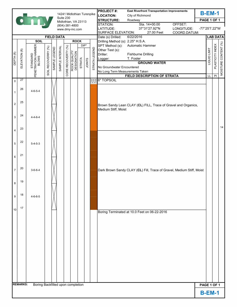
6" TOPSOIL
Brown Sandy Lean CLAY (CL) FILL, Trace of Gravel and Organics, Medium Stiff, Moist
Dark Brown Sandy CLAY (CL) Fill, Trace of Gravel, Medium Stiff, Moist
Boring Terminated at 10.0 Feet on 06-22-2016
2.25" H.S.A.

PROJECT #:LOCATION:STRUCTURE:STATION:LATITUDE: LONGITUDE:
Date (s) Drilled:Drilling Method (s):SPT Method (s):Other Test (s):Driller:Logger:
LL PI
0 25
24
23
22
21
20
19 7
18
17
16
15
REMARKS:
Roadway
LAB DATASURFACE ELEVATION:
LIQ
UID
LIM
IT
T. Fosler
PAGE 1 OF 1
PLAS
TIC
ITY
IND
EX
MO
ISTU
RE
CO
NTE
NT
(%)
37°31'27.02"NCOORD.DATUM:
OFFSET:Sta. 15+50.00-77°25'5.90"W
Groundwater Encountered at 9.5 Feet
Automatic HammerDIP*
5
3
7
B-EM-2
Boring Backfilled upon completion
5-8-6-4
PAGE 1 OF 1
8
9
10
3-4-3-4
2
6
4-3-2-1
4
2-4-5-17
2-3-2-31
25.00 Feet
14241 Midlothian Turenpike Suite 230Midlothian, VA 23113(804)-381-4800 www.dmy-inc.com
ROCK
East Riverfront Transportation ImprovementsB-EM-2City of Richmond
SAM
PLE
LEG
END
SOIL
REC
OVE
RR
Y (%
)
SAM
PLE
INTE
RVA
L
STR
ATA
LEG
END
JOIN
TS
GROUND WATER
2.25" H.S.A.FIELD DATA
ELEV
ATIO
N (f
t)
SOIL
Fishburne Drilling
STR
ATA
DEP
TH (f
t)
CO
RE
REC
OVE
RTY
(%)
RO
CK
QU
ALIT
Y D
ESIG
NAT
ION
6/22/2016
No Long Term Measurements TakenFIELD DESCRIPTION OF STRATA
STAN
DAR
D
PEN
ETR
ATIO
N H
AMM
ER
BLO
WS
6" TOPSOIL
Boring Terminated at 10.0 Feet on 06-22-2016
Dark Brown Sandy CLAY (CL) Fill, Trace of Gravel and Organics, Medium Stiff, Moist
Brown Clayey SAND (SC) FILL, Trace of Gravel and Organics, Medium Dense, Moist
Brown Clayey SAND (SC) FILL, Trace of Gravel, Medium Dense, Moist

PROJECT #:LOCATION:STRUCTURE:STATION:LATITUDE: LONGITUDE:
Date (s) Drilled:Drilling Method (s):SPT Method (s):Other Test (s):Driller:Logger:
LL PI
0 23
22
21
20
19
18
17
16
15 26
14
13
REMARKS:
Roadway
LAB DATASURFACE ELEVATION:
LIQ
UID
LIM
IT
T. Fosler
PAGE 1 OF 1
PLAS
TIC
ITY
IND
EX
MO
ISTU
RE
CO
NTE
NT
(%)
37°31'25.27"NCOORD.DATUM:
OFFSET:Sta. 18+10.00-77°25'4.80"W
No Groundwater Encountered
Automatic HammerDIP*
5
3
7
B-EM-3
Boring Backfilled upon completion
11-5-5-3
PAGE 1 OF 1
8
9
10
2-2-1-2
2
6
2-2-2-1
4
2-2-2-3
2-2-1-11
23.00 Feet
14241 Midlothian Turenpike Suite 230Midlothian, VA 23113(804)-381-4800 www.dmy-inc.com
ROCK
East Riverfront Transportation ImprovementsB-EM-3City of Richmond
SAM
PLE
LEG
END
SOIL
REC
OVE
RR
Y (%
)
SAM
PLE
INTE
RVA
L
STR
ATA
LEG
END
JOIN
TS
GROUND WATER
2.25" H.S.A.FIELD DATA
ELEV
ATIO
N (f
t)
SOIL
Fishburne Drilling
STR
ATA
DEP
TH (f
t)
CO
RE
REC
OVE
RTY
(%)
RO
CK
QU
ALIT
Y D
ESIG
NAT
ION
6/22/2016
No Long Term Measurements TakenFIELD DESCRIPTION OF STRATA
STAN
DAR
D
PEN
ETR
ATIO
N H
AMM
ER
BLO
WS
4" TOPSOIL
Boring Terminated at 10.0 Feet on 06-22-2016
Brown Clayey SAND (SC) FILL, Trace of Gravel and Organics, Very Loose, Moist
Dark Brown Sandy CLAY (CL) Fill, Trace of Gravel and Organics, Soft, Moist
Dark Brown Clayey SAND (SC) FILL, Trace of Gravel, Medium Dense, Moist
PROJECT #:LOCATION:STRUCTURE:STATION:LATITUDE: LONGITUDE:
Date (s) Drilled:Drilling Method (s):SPT Method (s):Other Test (s):Driller:Logger:
LL PI
0 25
24
23 5
22
21
20
19
18
17 31 11 16
16
15
REMARKS:
4" TOPSOIL
Boring Terminated at 10.0 Feet on 06-22-2016
Brown Clayey SAND (SC) FILL, Trace of Gravel and Organics, Very Loose, Moist
Dark Brown Sandy CLAY (CL) Fill, Trace of Gravel and Organics, Medium Stiff, Moist
2.25" H.S.A.FIELD DATA
ELEV
ATIO
N (f
t)
SOIL
Fishburne Drilling
STR
ATA
DEP
TH (f
t)
CO
RE
REC
OVE
RTY
(%)
RO
CK
QU
ALIT
Y D
ESIG
NAT
ION
6/22/2016
No Long Term Measurements TakenFIELD DESCRIPTION OF STRATA
STAN
DAR
D
PEN
ETR
ATIO
N H
AMM
ER
BLO
WS
25.00 Feet
14241 Midlothian Turenpike Suite 230Midlothian, VA 23113(804)-381-4800 www.dmy-inc.com
ROCK
East Riverfront Transportation ImprovementsB-EM-4City of Richmond
SAM
PLE
LEG
END
SOIL
REC
OVE
RR
Y (%
)
SAM
PLE
INTE
RVA
L
STR
ATA
LEG
END
JOIN
TS
GROUND WATER
2-2-2-3
2
6
2-1-2-2
4
3-3-3-4
2-2-2-21
B-EM-4
Boring Backfilled upon completion
4-6-5-4
PAGE 1 OF 1
8
9
10
DIP*
5
3
7
Roadway
LAB DATASURFACE ELEVATION:
LIQ
UID
LIM
IT
T. Fosler
PAGE 1 OF 1
PLAS
TIC
ITY
IND
EX
MO
ISTU
RE
CO
NTE
NT
(%)
37°31'23.88"NCOORD.DATUM:
OFFSET:Sta. 20+20.00-77°25'3.10"W
No Groundwater Encountered
Automatic Hammer
PROJECT #:LOCATION:STRUCTURE:STATION:LATITUDE: LONGITUDE:
Date (s) Drilled:Drilling Method (s):SPT Method (s):Other Test (s):Driller:Logger:
LL PI
0 25
24
23
22
21
59 36 22
20
19
18
17 19
16
15
REMARKS:
Roadway
LAB DATASURFACE ELEVATION:
LIQ
UID
LIM
IT
T. Fosler
PAGE 1 OF 1
PLAS
TIC
ITY
IND
EX
MO
ISTU
RE
CO
NTE
NT
(%)
37°31'21.46"NCOORD.DATUM:
OFFSET:Sta. 22+80.00-77°25'0.68"W
No Groundwater Encountered
Automatic HammerDIP*
5
3
7
B-EM-5
Boring Backfilled upon completion
4-6-6-5
PAGE 1 OF 1
8
9
10
8-7-6-5
2
6
3-4-3-5
4
4-4-4-4
2-8-6-61
25.00 Feet
14241 Midlothian Turenpike Suite 230Midlothian, VA 23113(804)-381-4800 www.dmy-inc.com
ROCK
East Riverfront Transportation ImprovementsB-EM-5City of Richmond
SAM
PLE
LEG
END
SOIL
REC
OVE
RR
Y (%
)
SAM
PLE
INTE
RVA
L
STR
ATA
LEG
END
JOIN
TS
GROUND WATER
FIELD DATA
ELEV
ATIO
N (f
t)
SOIL
Fishburne Drilling
STR
ATA
DEP
TH (f
t)
CO
RE
REC
OVE
RTY
(%)
RO
CK
QU
ALIT
Y D
ESIG
NAT
ION
6/22/2016
No Long Term Measurements TakenFIELD DESCRIPTION OF STRATA
STAN
DAR
D
PEN
ETR
ATIO
N H
AMM
ER
BLO
WS
2" TOPSOIL
Boring Terminated at 10.0 Feet on 06-22-2016
2.25" H.S.A.
Brown Clayey SAND (SC) FILL, Trace of Gravel and Organics, Very Loose, Moist
Dark Brown Sandy High Plasticity CLAY (CH) Fill, Trace of Gravel and Organics, Medium Stiff, Moist
PROJECT #:LOCATION:STRUCTURE:STATION:LATITUDE: LONGITUDE:
Date (s) Drilled:Drilling Method (s):SPT Method (s):Other Test (s):Driller:Logger:
LL PI
0 27
26
25
24
23
22
21
20
19
18
17
REMARKS:
4" TOPSOIL
Boring Terminated at 10.0 Feet on 06-21-2016
Dark Brown Clayey SAND (SC) Fill, Trace of Gravel and Organics, Very Loose, Moist
Brown Clayey SAND (SC) FILL, Trace of Gravel and Organics, Loose, Moist
Brown Sandy CLAY (CL) FILL, Trace of Gravel and Organics, Medium Stiff, Moist
2.25" H.S.A.FIELD DATA
ELEV
ATIO
N (f
t)
SOIL
Fishburne Drilling
STR
ATA
DEP
TH (f
t)
CO
RE
REC
OVE
RTY
(%)
RO
CK
QU
ALIT
Y D
ESIG
NAT
ION
6/21/2016
No Long Term Measurements TakenFIELD DESCRIPTION OF STRATA
STAN
DAR
D
PEN
ETR
ATIO
N H
AMM
ER
BLO
WS
27.00 Feet
14241 Midlothian Turenpike Suite 230Midlothian, VA 23113(804)-381-4800 www.dmy-inc.com
ROCK
East Riverfront Transportation ImprovementsB-EM-6City of Richmond
SAM
PLE
LEG
END
SOIL
REC
OVE
RR
Y (%
)
SAM
PLE
INTE
RVA
L
STR
ATA
LEG
END
JOIN
TS
GROUND WATER
4-5-5-5
2
6
4-4-4-3
4
2-3-2-3
2-3-4-21
B-EM-6
Boring Backfilled upon completion
2-2-2-2
PAGE 1 OF 1
8
9
10
DIP*
5
3
7
Roadway
LAB DATASURFACE ELEVATION:
LIQ
UID
LIM
IT
T. Fosler
PAGE 1 OF 1
PLAS
TIC
ITY
IND
EX
MO
ISTU
RE
CO
NTE
NT
(%)
37°31'19.17"NCOORD.DATUM:
OFFSET:Sta. 24+85.00-77°24'59.33"W
No Groundwater Encountered
Automatic Hammer
PROJECT #:LOCATION:STRUCTURE:STATION:LATITUDE: LONGITUDE:
Date (s) Drilled:Drilling Method (s):SPT Method (s):Other Test (s):Driller:Logger:
LL PI
0 27
26
25
24
23 34
22
21
20
19
18
17
REMARKS:
Roadway
LAB DATASURFACE ELEVATION:
LIQ
UID
LIM
IT
T. Fosler
PAGE 1 OF 1
PLAS
TIC
ITY
IND
EX
MO
ISTU
RE
CO
NTE
NT
(%)
37°31'17.34"NCOORD.DATUM:
OFFSET:Sta. 27+50.00-77°24'58.29"W
No Groundwater Encountered
Automatic HammerDIP*
5
3
7
B-EM-7
Boring Backfilled upon completion
2-2-1-1
PAGE 1 OF 1
8
9
10
4-4-3-3
2
6
2-3-1-2
4
2-2-1-1
3-3-3-31
27.00 Feet
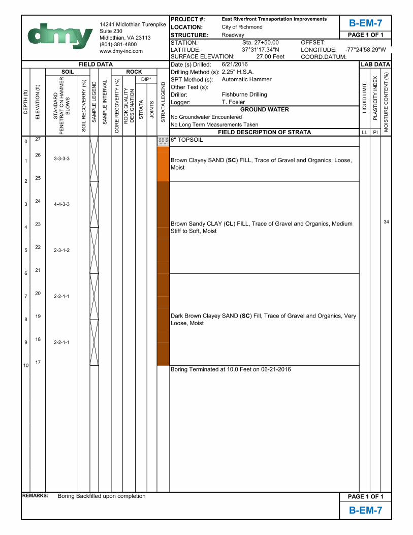
14241 Midlothian Turenpike Suite 230Midlothian, VA 23113(804)-381-4800 www.dmy-inc.com
ROCK
East Riverfront Transportation ImprovementsB-EM-7City of Richmond
SAM
PLE
LEG
END
SOIL
REC
OVE
RR
Y (%
)
SAM
PLE
INTE
RVA
L
STR
ATA
LEG
END
JOIN
TS
GROUND WATER
2.25" H.S.A.FIELD DATA
ELEV
ATIO
N (f
t)
SOIL
Fishburne Drilling
STR
ATA
DEP
TH (f
t)
CO
RE
REC
OVE
RTY
(%)
RO
CK
QU
ALIT
Y D
ESIG
NAT
ION
6/21/2016
No Long Term Measurements TakenFIELD DESCRIPTION OF STRATA
STAN
DAR
D
PEN
ETR
ATIO
N H
AMM
ER
BLO
WS
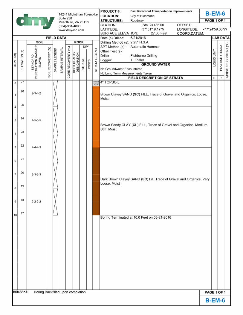
6" TOPSOIL
Boring Terminated at 10.0 Feet on 06-21-2016
Dark Brown Clayey SAND (SC) Fill, Trace of Gravel and Organics, Very Loose, Moist
Brown Clayey SAND (SC) FILL, Trace of Gravel and Organics, Loose, Moist
Brown Sandy CLAY (CL) FILL, Trace of Gravel and Organics, Medium Stiff to Soft, Moist
PROJECT #:LOCATION:STRUCTURE:STATION:LATITUDE: LONGITUDE:
Date (s) Drilled:Drilling Method (s):SPT Method (s):Other Test (s):Driller:Logger:
LL PI0 28
27
26
25
24 16
23
22
21
20
19
18
REMARKS:
Roadway
LAB DATASURFACE ELEVATION:
LIQ
UID
LIM
IT
T. Fosler
PAGE 1 OF 1
PLAS
TIC
ITY
IND
EX
MO
ISTU
RE
CO
NTE
NT
(%)
37°31'14.79"NCOORD.DATUM:
OFFSET:Sta. 29+20.00-77°24'57.17"W
28.00 Feet
DIP*
5
3
7
3-4-5-59
10
6
6-4-2-2
4
No Long Term Measurements TakenFIELD DESCRIPTION OF STRATA
1-2-2-2
STAN
DAR
D
PEN
ETR
ATIO
N H
AMM
ER
BLO
WS
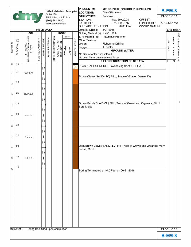
10-20-271
3" ASPHALT CONCRETE overlaying 9" AGGREGATE
Brown Clayey SAND (SC) FILL, Trace of Gravel, Dense, Dry
8
ELEV
ATIO
N (f
t)
PAGE 1 OF 1
Boring Terminated at 10.0 Feet on 06-21-2016
Dark Brown Clayey SAND (SC) Fill, Trace of Gravel and Organics, Very Loose, Moist
Brown Sandy CLAY (CL) FILL, Trace of Gravel and Organics, Stiff to Soft, Moist
B-EM-8
Boring Backfilled upon completion
14241 Midlothian Turenpike Suite 230Midlothian, VA 23113(804)-381-4800 www.dmy-inc.com
ROCK
East Riverfront Transportation ImprovementsB-EM-8City of Richmond
SAM
PLE
LEG
END
SOIL
REC
OVE
RR
Y (%
)
SAM
PLE
INTE
RVA
L
STR
ATA
LEG
END
JOIN
TS
GROUND WATERNo Groundwater Encountered
Automatic Hammer2.25" H.S.A.
FIELD DATA 6/21/2016
12-15-8-9
2
SOIL
Fishburne Drilling
STR
ATA
DEP
TH (f
t)
CO
RE
REC
OVE
RTY
(%)
RO
CK
QU
ALIT
Y D
ESIG
NAT
ION
PROJECT #:LOCATION:STRUCTURE:STATION:LATITUDE: LONGITUDE:
Date (s) Drilled:Drilling Method (s):SPT Method (s):Other Test (s):Driller:Logger:
LL PI0 14
1
11
10
9
8
7
6
5
4
3
2
1 5
0
-1
REMARKS:
Brown Clayey SAND (SC) FILL, Trace of Gravel and Organics, Loose, Wet
124" AGGREGATE
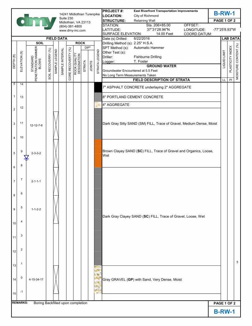
Dark Gray Silty SAND (SM) FILL, Trace of Gravel, Medium Dense, Moist
2.25" H.S.A.FIELD DATA
ELEV
ATIO
N (f
t)
SOIL
Fishburne Drilling
STR
ATA
DEP
TH (f
t)
CO
RE
REC
OVE
RTY
(%)
RO
CK
QU
ALIT
Y D
ESIG
NAT
ION
8" PORTLAND CEMENT CONCRETE
12-12-7-6
2
7" ASPHALT CONCRETE underlaying 2" AGGREGATE
Automatic Hammer
STAN
DAR
D
PEN
ETR
ATIO
N H
AMM
ER
BLO
WS
6/22/2016
Retaining Wall
LAB DATASURFACE ELEVATION:
LIQ
UID
LIM
IT
PAGE 1 OF 2
PLAS
TIC
ITY
IND
EX
MO
ISTU
RE
CO
NTE
NT
(%)
37°31'28.96"N
B-RW-1
Boring Backfilled upon completion PAGE 1 OF 2
15
8
14
11
12
13
9
10
Dark Gray Clayey SAND (SC) FILL, Trace of Gravel, Loose, Wet
Gray GRAVEL (GP) with Sand, Very Dense, Moist4-15-34-17
1-1-2-2
2-1-1-1
4
13
DIP*
5
3
7
T. Fosler
6
2-3-3-2
COORD.DATUM:
OFFSET:Sta. 206+85.00-77°25'8.93"W
No Long Term Measurements TakenFIELD DESCRIPTION OF STRATA
14.00 Feet
14241 Midlothian Turenpike Suite 230Midlothian, VA 23113(804)-381-4800 www.dmy-inc.com
ROCK
East Riverfront Transportation ImprovementsB-RW-1City of Richmond
SAM
PLE
LEG
END
SOIL
REC
OVE
RR
Y (%
)
SAM
PLE
INTE
RVA
L
STR
ATA
LEG
END
JOIN
TS
GROUND WATERGroundwater Encountered at 5.5 Feet
PROJECT #:LOCATION:STRUCTURE:STATION:LATITUDE: LONGITUDE:
Date (s) Drilled:Drilling Method (s):SPT Method (s):Other Test (s):Driller:Logger:
LL PI15 -1
-2
-3
-4
-5
-6
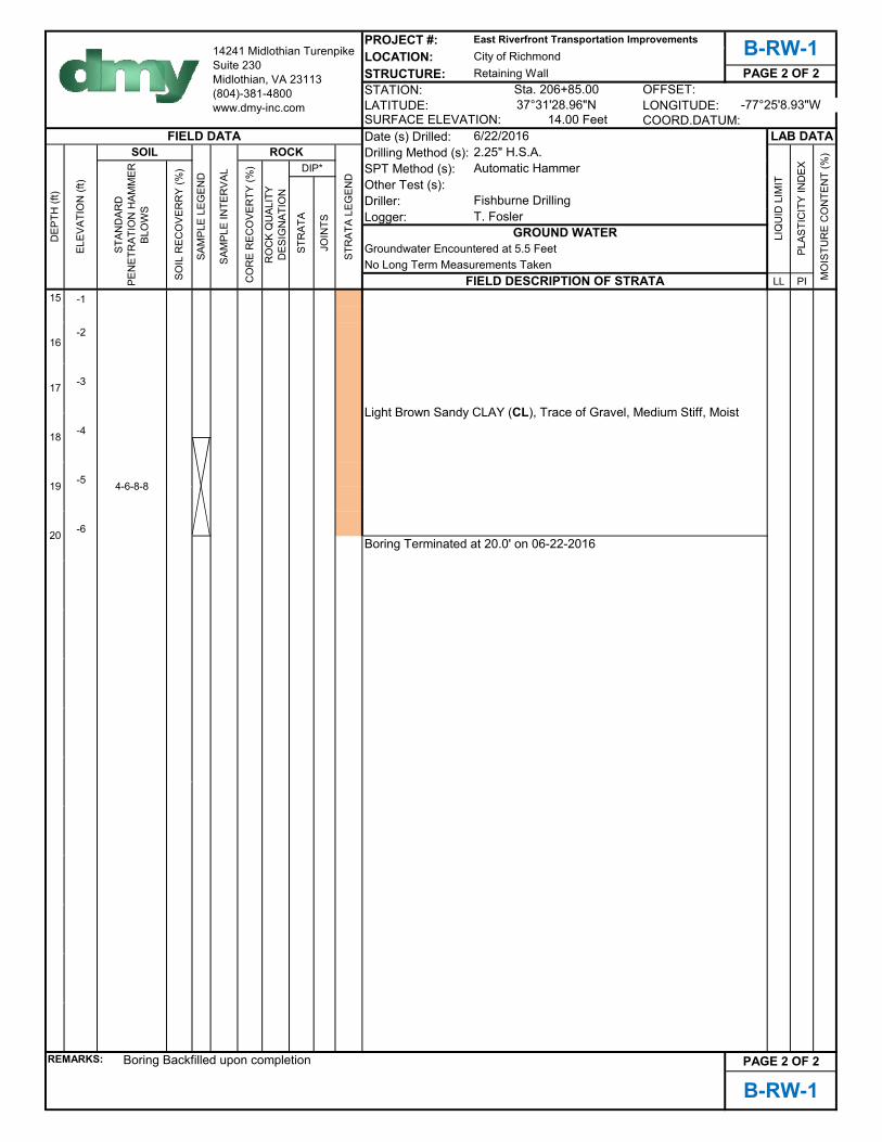
REMARKS: PAGE 2 OF 2
B-RW-1
Boring Backfilled upon completion
4-6-8-8
16
17
18
20
19
FIELD DATA 6/22/2016 LAB DATA
DEP
TH (f
t)
ELEV
ATIO
N (f
t)
SOIL
SAM
PLE
LEG
END
SAM
PLE
INTE
RVA
L
ROCK
STR
ATA
LEG
END
2.25" H.S.A.
LIQ
UID
LIM
IT
PLAS
TIC
ITY
IND
EX
MO
ISTU
RE
CO
NTE
NT
(%)
STAN
DAR
D
PEN
ETR
ATIO
N H
AMM
ER
BLO
WS
SOIL
REC
OVE
RR
Y (%
)
14241 Midlothian Turenpike Suite 230Midlothian, VA 23113(804)-381-4800 www.dmy-inc.com
East Riverfront Transportation Improvements
37°31'28.96"N
CO
RE
REC
OVE
RTY
(%)
RO
CK
QU
ALIT
Y D
ESIG
NAT
ION
DIP* Automatic Hammer
STR
ATA
JOIN
TS
Fishburne DrillingT. Fosler
GROUND WATER
B-RW-1City of RichmondRetaining Wall PAGE 2 OF 2
Sta. 206+85.00 OFFSET:-77°25'8.93"W
SURFACE ELEVATION: 14.00 Feet COORD.DATUM:
Groundwater Encountered at 5.5 FeetNo Long Term Measurements Taken
FIELD DESCRIPTION OF STRATA
Light Brown Sandy CLAY (CL), Trace of Gravel, Medium Stiff, Moist
Boring Terminated at 20.0' on 06-22-2016

PROJECT #:LOCATION:STRUCTURE:STATION:LATITUDE: LONGITUDE:
Date (s) Drilled:Drilling Method (s):SPT Method (s):Other Test (s):Driller:Logger:
LL PI0 12
1
9
8
7
6
18
5
4
3
2
1
0
-1
-2
-3
REMARKS:
COORD.DATUM:
OFFSET:Sta. 209+10.00-77°25'7.37"W
No Long Term Measurements TakenFIELD DESCRIPTION OF STRATA
12.00 Feet
2.25" H.S.A.DIP*
5
3
7
T. Fosler
6
1-1-2-2
B-RW-2
Boring Backfilled upon completion PAGE 1 OF 1
15
8
14
11
12
13
9
10
Light Brown Silty SAND (SM) with Gravel, Very Dense, Moist
Gray Silty SAND (SM) FILL, Trace of Gravel, Very Dense, Moist
Boring Terminated at 15.0 Feet on 06-22-2016
14241 Midlothian Turenpike Suite 230Midlothian, VA 23113(804)-381-4800 www.dmy-inc.com
ROCK
East Riverfront Transportation ImprovementsB-RW-2City of Richmond
SAM
PLE
LEG
END
SOIL
REC
OVE
RR
Y (%
)
SAM
PLE
INTE
RVA
L
STR
ATA
LEG
END
JOIN
TS
GROUND WATERNo Groundwater Encountered
Automatic Hammer
STAN
DAR
D
PEN
ETR
ATIO
N H
AMM
ER
BLO
WS
6/22/2016
Retaining Wall
LAB DATASURFACE ELEVATION:
LIQ
UID
LIM
IT
PAGE 1 OF 1
PLAS
TIC
ITY
IND
EX
MO
ISTU
RE
CO
NTE
NT
(%)
37°31'27.02"N
FIELD DATA
ELEV
ATIO
N (f
t)
SOIL
Fishburne Drilling
STR
ATA
DEP
TH (f
t)
CO
RE
REC
OVE
RTY
(%)
RO
CK
QU
ALIT
Y D
ESIG
NAT
ION
5-2-2-3
2
9" ASPHALT CONCRETE
50/2
4
11
10
7" PORTLAND CEMENT CONCRETE underlaying 3" AGGREGATE
12-15-20-20
2-3-5-7
Light Brown Silty SAND (SM) FILL, Trace of Gravel, Medium Dense to Loose, Moist

PROJECT #:LOCATION:STRUCTURE:STATION:LATITUDE: LONGITUDE:
Date (s) Drilled:Drilling Method (s):SPT Method (s):Other Test (s):Driller:Logger:
LL PI0 24
23
22
21
20 10
19
18
17
16
15
14
13
12
11
10
9
REMARKS:
14241 Midlothian Turenpike Suite 230Midlothian, VA 23113(804)-381-4800 www.dmy-inc.com
ROCK
East Riverfront Transportation Improvements
1
2.25" H.S.A.FIELD DATA
ELEV
ATIO
N (f
t)
SOIL
Fishburne Drilling
STR
ATA
DEP
TH (f
t)
CO
RE
REC
OVE
RTY
(%)
RO
CK
QU
ALIT
Y D
ESIG
NAT
ION
B-SP-1
37°31'13.41"NCOORD.DATUM:
OFFSET:Sta. 301+75.00-77°24'56.19"W
23.70 Feet
City of RichmondPAGE 1 OF 2
6/21/2016
Signal Post
LAB DATASURFACE ELEVATION:
7
2
4-5-7-5
T. FoslerSA
MPL
E LE
GEN
D
SOIL
REC
OVE
RR
Y (%
)
4
5
2" TOPSOIL
Brown Silty SAND (SM) FILL, Trace of Gravel and Organics, Loose to Medium Dense, Moist
Light Brown Sandy CLAY (CL) FILL, Trace of Gravel and Organics, Soft, Wet
4-4-2-2
13
9
6
10
MO
ISTU
RE
CO
NTE
NT
(%)
LIQ
UID
LIM
IT
1-2-7-11
3-4-6-4
4-6-4-3
1-2-4-5
Brown Silty SAND (SM) FILL, Trace of Gravel, Caly, and Organics, Loose to Medium Dense, Moist
STR
ATA
LEG
END
JOIN
TS
GROUND WATERGroundwater Encountered at 12.0 Feet
Automatic Hammer
No Long Term Measurements TakenFIELD DESCRIPTION OF STRATA
B-SP-1
Boring Backfilled upon completion
DIP*
Gray Silty SAND (SM), Trace of Gravel, Medium Dense to Dense, Moist
PLAS
TIC
ITY
IND
EX
SAM
PLE
INTE
RVA
L
PAGE 1 OF 2
15
8
3
STAN
DAR
D
PEN
ETR
ATIO
N H
AMM
ER
BLO
WS
14
11
12

PROJECT #:LOCATION:STRUCTURE:STATION:LATITUDE: LONGITUDE:
Date (s) Drilled:Drilling Method (s):SPT Method (s):Other Test (s):Driller:Logger:
LL PI15 9
8
7
6
5
4
3
2
1
0
-1
-2
-3
-4
-5
-6
REMARKS:
Boring Terminated at 30.0' on 06-21-2016
Grey Silty SAND (SM), Trace of Gravel, Dense to Medium Dense, Moist
PAGE 2 OF 2
B-SP-1
Boring Backfilled upon completion
29
30
6-15-19-24
6-8-10-11
19
24
25
26
6-16-27-20
27
28
Groundwater Encountered at 12.0 FeetNo Long Term Measurements Taken
FIELD DESCRIPTION OF STRATA
20
21
22
23
16
17
18
Grey Silty SAND (SM), Trace of Gravel, Medium Dense to Very Dense, Moist
FIELD DATA 6/21/2016 LAB DATA
DEP
TH (f
t)
ELEV
ATIO
N (f
t)
SOIL
SAM
PLE
LEG
END
SAM
PLE
INTE
RVA
L
ROCK
STR
ATA
LEG
END
2.25" H.S.A.
LIQ
UID
LIM
IT
PLAS
TIC
ITY
IND
EX
MO
ISTU
RE
CO
NTE
NT
(%)
STAN
DAR
D
PEN
ETR
ATIO
N H
AMM
ER
BLO
WS
SOIL
REC
OVE
RR
Y (%
)
14241 Midlothian Turenpike Suite 230Midlothian, VA 23113(804)-381-4800 www.dmy-inc.com
East Riverfront Transportation Improvements
37°31'13.41"N
CO
RE
REC
OVE
RTY
(%)
RO
CK
QU
ALIT
Y D
ESIG
NAT
ION
DIP* Automatic Hammer
STR
ATA
JOIN
TS
Fishburne DrillingT. Fosler
GROUND WATER
B-SP-1City of RichmondSignal Post PAGE 2 OF 2
Sta. 301+75.00 OFFSET:-77°24'56.19"W
SURFACE ELEVATION: 23.70 Feet COORD.DATUM:

PROJECT #:LOCATION:STRUCTURE:STATION:LATITUDE: LONGITUDE:
Date (s) Drilled:Drilling Method (s):SPT Method (s):Other Test (s):Driller:Logger:
LL PI0 26
25
24
23
22
21
20 39
19
18 25 9 16
17
16
15
14
13
12
11
REMARKS:
6/21/2016
No Long Term Measurements TakenFIELD DESCRIPTION OF STRATA
STAN
DAR
D
PEN
ETR
ATIO
N H
AMM
ER
BLO
WS
SOIL
Fishburne Drilling
STR
ATA
DEP
TH (f
t)
CO
RE
REC
OVE
RTY
(%)
RO
CK
QU
ALIT
Y D
ESIG
NAT
ION
Gray Silty SAND (SM), Trace of Gravel, Loose, Moist
2-1-1-2
26.00 Feet
14241 Midlothian Turenpike Suite 230Midlothian, VA 23113(804)-381-4800 www.dmy-inc.com
ROCK
East Riverfront Transportation ImprovementsB-SP-2City of Richmond
SAM
PLE
LEG
END
SOIL
REC
OVE
RR
Y (%
)
SAM
PLE
INTE
RVA
L
STR
ATA
LEG
END
JOIN
TS
15
8
14
11
12
13
9
10
4
4-4-3-4
-/-/-3-51
5
3
B-SP-2
Boring Backfilled upon completion
1-2-2-1
4-4-5-4
2
6
4-2-3-4
Sta. 31+85.00
Brown Sandy Lean CLAY (CL) FILL, Trace of Gravel and Organics, Medium Stiff, Moist
DIP*
4" ASPHALT CONCRETE underlaying 5" GRAVEL
PAGE 1 OF 2
GROUND WATERGroundwater Encountered at 5.5 Feet
Automatic Hammer2.25" H.S.A.
FIELD DATA
ELEV
ATIO
N (f
t)
-77°24'56.43"W
7
Signal Post
LAB DATA
Brown Sandy Lean CLAY (CL) FILL, Trace of Gravel and Organics, Soft to Very Soft, Wet
Light Brown Silty SAND (SM) FILL, Trace of Gravel, Medium Dense, Moist
SURFACE ELEVATION:
LIQ
UID
LIM
IT
T. Fosler
PAGE 1 OF 2
PLAS
TIC
ITY
IND
EX
MO
ISTU
RE
CO
NTE
NT
(%)
37°31'12.99"NCOORD.DATUM:
OFFSET:

PROJECT #:LOCATION:STRUCTURE:STATION:LATITUDE: LONGITUDE:
Date (s) Drilled:Drilling Method (s):SPT Method (s):Other Test (s):Driller:Logger:
LL PI15 11
10
9
8
7
6
5
4
3
2
1 16
0
-1
-2
-3
-4
REMARKS:
Boring Terminated at 30.0' on 06-21-2016
Grey Clayey SAND (SC), Trace of Gravel, Very Dense to Medium Dense, Moist
PAGE 2 OF 2
B-SP-2
Boring Backfilled upon completion
29
30
12-24-50/6
4-5-6-8
19
24
25
26
11-19-19-17
27
28
Groundwater Encountered at 5.5 FeetNo Long Term Measurements Taken
FIELD DESCRIPTION OF STRATA
20
21
22
23
16
17
18
Grey Silty SAND (SM), Trace of Gravel, Medium Dense to Very Dense, Moist
FIELD DATA 6/21/2016 LAB DATA
DEP
TH (f
t)
ELEV
ATIO
N (f
t)
SOIL
SAM
PLE
LEG
END
SAM
PLE
INTE
RVA
L
ROCK
STR
ATA
LEG
END
2.25" H.S.A.
LIQ
UID
LIM
IT
PLAS
TIC
ITY
IND
EX
MO
ISTU
RE
CO
NTE
NT
(%)
STAN
DAR
D
PEN
ETR
ATIO
N H
AMM
ER
BLO
WS
SOIL
REC
OVE
RR
Y (%
)
14241 Midlothian Turenpike Suite 230Midlothian, VA 23113(804)-381-4800 www.dmy-inc.com
East Riverfront Transportation Improvements
37°31'12.99"N
CO
RE
REC
OVE
RTY
(%)
RO
CK
QU
ALIT
Y D
ESIG
NAT
ION
DIP* Automatic Hammer
STR
ATA
JOIN
TS
Fishburne DrillingT. Fosler
GROUND WATER
B-SP-2City of RichmondSignal Post PAGE 2 OF 2
Sta. 31+85.00 OFFSET:-77°24'56.43"W
SURFACE ELEVATION: 26.00 Feet COORD.DATUM:

PROJECT #:LOCATION:STRUCTURE:STATION:LATITUDE: LONGITUDE:
Date (s) Drilled:Drilling Method (s):SPT Method (s):Other Test (s):Driller:Logger:
LL PI0 25
24
23
22
21
20
19
18
17
16
15
14
13
12
11
10
REMARKS:
6/21/2016
14241 Midlothian Turenpike Suite 230Midlothian, VA 23113(804)-381-4800 www.dmy-inc.com
ROCK
East Riverfront Transportation ImprovementsB-SP-3City of Richmond
SAM
PLE
LEG
END
SOIL
REC
OVE
RR
Y (%
)
SAM
PLE
INTE
RVA
L
STR
ATA
LEG
END
JOIN
TS
GROUND WATERGroundwater Encountered at 14.0 Feet
Automatic Hammer2.25" H.S.A.
10
1-2-3-5
3-3-2-3
4-3-2-1
25.00 Feet
1
FIELD DATA
ELEV
ATIO
N (f
t)
SOIL
Fishburne Drilling
STR
ATA
DEP
TH (f
t)
CO
RE
REC
OVE
RTY
(%)
RO
CK
QU
ALIT
Y D
ESIG
NAT
ION
STAN
DAR
D
PEN
ETR
ATIO
N H
AMM
ER
BLO
WS
5-7-5-4
2
4" TOPSOIL
6
2-1-2-2
4
Brown Silty SAND (SM) FILL, Trace of Gravel, Medium Dense, Moist
Gray Sandy Lean CLAY (CL) FILL, Trace of Gravel and Organics, Soft to Very Soft, Wet
Brown Silty SAND (SM), Trace of Gravel, Loose to Medium Dense, Moist
4-3-3-2
PAGE 1 OF 2
15
8
14
B-SP-3
Boring Backfilled upon completion
11
12
13
9
DIP*
5
3
7
Signal Post
LAB DATASURFACE ELEVATION:
LIQ
UID
LIM
IT
T. Fosler
PAGE 1 OF 2
PLAS
TIC
ITY
IND
EX
MO
ISTU
RE
CO
NTE
NT
(%)
37°31'12.81"NCOORD.DATUM:
OFFSET:Sta. 31+70.00-77°24'57.75"W
No Long Term Measurements TakenFIELD DESCRIPTION OF STRATA

PROJECT #:LOCATION:STRUCTURE:STATION:LATITUDE: LONGITUDE:
Date (s) Drilled:Drilling Method (s):SPT Method (s):Other Test (s):Driller:Logger:
LL PI15 10
9
8
7 9
6
5
4
3
2
1
0
-1
-2
-3
-4
-5
REMARKS:
Boring Terminated at 30.0' on 06-21-2016
PAGE 2 OF 2
B-SP-3
Boring Backfilled upon completion
29
30
11-11-11-13
24
25
26
15-21-32-39
27
28
16
17
18
20
21
22
23
14-26-50/5
19
FIELD DATA 6/21/2016 LAB DATA
DEP
TH (f
t)
ELEV
ATIO
N (f
t)
SOIL
SAM
PLE
LEG
END
SAM
PLE
INTE
RVA
L
ROCK
STR
ATA
LEG
END
2.25" H.S.A.
LIQ
UID
LIM
IT
PLAS
TIC
ITY
IND
EX
MO
ISTU
RE
CO
NTE
NT
(%)
STAN
DAR
D
PEN
ETR
ATIO
N H
AMM
ER
BLO
WS
SOIL
REC
OVE
RR
Y (%
)
14241 Midlothian Turenpike Suite 230Midlothian, VA 23113(804)-381-4800 www.dmy-inc.com
East Riverfront Transportation Improvements
37°31'12.81"N
CO
RE
REC
OVE
RTY
(%)
RO
CK
QU
ALIT
Y D
ESIG
NAT
ION
DIP* Automatic Hammer
STR
ATA
JOIN
TS
Fishburne DrillingT. Fosler
GROUND WATER
B-SP-3City of RichmondSignal Post PAGE 2 OF 2
Sta. 31+70.00 OFFSET:
Brown Silty SAND (SM), Trace of Gravel, Medium Dense, Moist
Grey Clayey SAND (SC), Trace of Gravel, Dense to Very Dense, Moist
-77°24'57.75"WSURFACE ELEVATION: 25.00 Feet COORD.DATUM:
Groundwater Encountered at 14.0 FeetNo Long Term Measurements Taken
FIELD DESCRIPTION OF STRATA

0
20
40
60
80
0 20 40 60 80 100
ML
CL
LIQUID LIMIT
B-DS-1
B-EM-4
B-EM-5
B-SP-2
FinesPIPL TestingLab
SANDY FAT CLAY (CH), dark brown, black and gray(Visual)
SANDY LEAN CLAY (CL), dark brown (Visual)
SANDY FAT CLAY (CH), trace gravel, light brown (Visual)
SANDY LEAN CLAY (CL), trace gravel, contains petroleumodor, dark gray (Visual)
LLSpecimen
PLOTTED DATA REPRESENTS SOIL PASSING NO. 40 SIEVE
52
31
59
25
26
20
23
16
26
11
36
9
CL-ML MH
CH
Description
RICH
RICH
RICH
RICH
PLA
ST
ICIT
Y IN
DE
X
ATTERBERG LIMITS
4.0 ft
6.0 ft
4.0 ft
8.0 ft
Project: City of RichmondEast Riverfront Transportation ImprovementsRichmond, VA
Contract: 12613036AT
TE
RB
ER
G_L
IMIT
S 1
261
303
6 T
AS
K 2
5 L
AB
DA
TA
.GP
J S
CH
NA
BE
L D
AT
A T
EM
PLA
TE
200
8_0
4_2
2.G
DT
7/8
/16
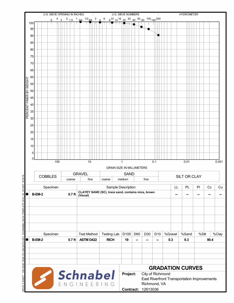
0
5
10
15
20
25
30
35
40
45
50
55
60
65
70
75
80
85
90
95
100
0.0010.010.1110100
4 3
GRAIN SIZE IN MILLIMETERS
PE
RC
EN
T F
INE
R B
Y W
EIG
HT
U.S. SIEVE OPENING IN INCHES
200100 1406040
0.3
23 3/41.5 6
CLAYEY SAND (SC), trace sand, contains mica, brown (Visual)
Specimen
--
LL
U.S. SIEVE NUMBERS
5030
GRADATION CURVES
1/23/8
PL PI Cc Cu
B-EM-2 -- -- --
%Clay
B-EM-2
%Silt%GravelSpecimen
Sample Description
D30
16 2014
%Sand
ASTM D422 9.3
81041
90.4
HYDROMETER
6
Test Method D10
----
D60
--
D100
19RICH
Testing Lab
--0.7 ft
0.7 ft
Project: City of RichmondEast Riverfront Transportation ImprovementsRichmond, VA
Contract: 12613036SIE
VE
5 S
HE
ET
126
130
36 T
AS
K 2
5 L
AB
DA
TA
.GP
J S
CH
NA
BE
L D
AT
A T
EM
PLA
TE
201
0_0
2_2
5.G
DT
8/1
0/1
6
fine coarseCOBBLES SILT OR CLAY
medium fine
SANDGRAVELcoarse
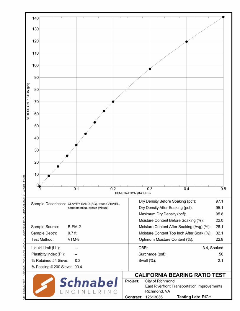
0
10
20
30
40
50
60
70
80
90
100
110
120
130
140
0 0.1 0.2 0.3 0.4 0.5
3.4, Soaked
Dry Density Before Soaking (pcf):
Dry Density After Soaking (pcf):
Maximum Dry Density (pcf):
Moisture Content Before Soaking (%):
Moisture Content After Soaking (Avg) (%):
Sample Description:
PENETRATION (INCHES)
CALIFORNIA BEARING RATIO TEST
Surcharge (psf):
CBR:
2.1
50
Optimum Moisture Content (%): 22.8
26.1
22.0
95.8
95.1
97.1
Swell (%):
ST
RE
SS
ON
PIS
TO
N (
psi)
Test Method:
Sample Depth:
B-EM-2
VTM-8
Sample Source:
CLAYEY SAND (SC), trace GRAVEL, contains mica, brown (Visual)
0.7 ft Moisture Content Top Inch After Soak (%): 32.1
RICHTesting Lab:
Project: City of RichmondEast Riverfront Transportation ImprovementsRichmond, VA
Contract: 12613036
Liquid Limit (LL): --
Plasticity Index (PI): --
% Passing # 200 Sieve: 90.4
% Retained #4 Sieve: 0.3
CB
R S
ING
LE P
OIN
T 1
261
3036
TA
SK
25
LA
B D
AT
A.G
PJ
SC
HN
AB
EL
DA
TA
TE
MP
LAT
E 2
008
_04_
22.
GD
T 8
/10
/16
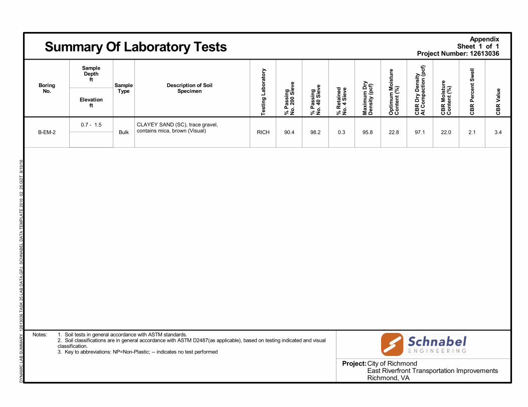
B-EM-2
0.7 - 1.5
Bulk
CLAYEY SAND (SC), trace gravel, contains mica, brown (Visual) RICH 90.4 98.2 0.3 95.8 22.8 97.1 22.0 2.1 3.4
Sheet 1 of 1
BoringNo.
Summary Of Laboratory TestsAppendix
Description of SoilSpecimen
Project Number: 12613036
Notes: 1. Soil tests in general accordance with ASTM standards.2. Soil classifications are in general accordance with ASTM D2487(as applicable), based on testing indicated and visualclassification.3. Key to abbreviations: NP=Non-Plastic; -- indicates no test performed
Project:
Elevationft
City of RichmondEast Riverfront Transportation ImprovementsRichmond, VA
SampleType
SampleDepth
ft
DY
NA
MIC
LA
B S
UM
MA
RY
12
613
036
TA
SK
25
LA
B D
AT
A.G
PJ
SC
HN
AB
EL
DA
TA
TE
MP
LAT
E 2
010
_02_
25.
GD
T 8
/10
/16
CB
R D
ry D
ensi
tyA
t C
om
pac
tio
n (
pcf
)
CB
R M
ois
ture
Co
nte
nt
(%)
Max
imu
m D
ryD
ensi
ty (
pcf
)
CB
R V
alu
e
% P
assi
ng
No
. 40
Sie
ve
Op
tim
um
Mo
istu
reC
on
ten
t (%
)
% P
assi
ng
No
. 200
Sie
ve
% R
etai
ned
No
. 4 S
ieve
Tes
tin
g L
abo
rato
ry
CB
R P
erce
nt
Sw
ell

0
5
10
15
20
25
30
35
40
45
50
55
60
65
70
75
80
85
90
95
100
0.0010.010.1110100
4 3
GRAIN SIZE IN MILLIMETERS
PE
RC
EN
T F
INE
R B
Y W
EIG
HT
U.S. SIEVE OPENING IN INCHES
200100 1406040
1.5
12.7
4.0
3.3
23 3/41.5 6
CLAYEY SAND WITH GRAVEL (SC), fine to coarse grainedsand, contains rock and coal fragments, gray (Visual)
CLAYEY SAND (SC), fine to coarse grained sand, trace gravel,dark gray (Visual)
SILTY SAND (SM), fine to coarse grained sand, trace gravel,gray (Visual)
CLAYEY SAND (SC), fine to coarse sand, contains rockfragments, gray (Visual)
Specimen
--
--
--
--
LL
U.S. SIEVE NUMBERS
5030
GRADATION CURVES
1/23/8
PL PI Cc Cu
B-DS-3
B-RW-1
B-RW-2
B-SP-2
--
--
--
--
--
--
--
--
--
--
--
--
%Clay
B-DS-3
B-RW-1
B-RW-2
B-SP-2
%Silt%GravelSpecimen
Sample Description
D30
16 2014
%Sand
ASTM D422
ASTM D422
ASTM D422
ASTM D422
64.6
58.4
69.1
63.8
81041
33.9
28.9
26.9
32.9
HYDROMETER
6
Test Method D10
--
--
--
--
--
0.08
0.1
--
D60
0.32
0.57
0.55
0.43
D100
19
19
19
9.5
RICH
RICH
RICH
RICH
Testing Lab
--
--
--
--
2.0 ft
6.0 ft
4.0 ft
23.0 ft
2.0 ft
6.0 ft
4.0 ft
23.0 ft
Project: City of RichmondEast Riverfront Transportation ImprovementsRichmond, VA
Contract: 12613036SIE
VE
5 S
HE
ET
126
130
36 T
AS
K 2
5 L
AB
DA
TA
.GP
J S
CH
NA
BE
L D
AT
A T
EM
PLA
TE
201
0_0
2_2
5.G
DT
7/8
/16
fine coarseCOBBLES SILT OR CLAY
medium fine
SANDGRAVELcoarse

Project No.
Boring No. B-DS-1 B-DS-2 B-DS-3 B-EM-1 B-EM-2 B-EM-3Depth (ft) 4.0 4.0 8.0 4.0 6.0 8.0Tare No. T28 T4 T11 T1 40 T10
Wgt. Tare + Wet Wgt, gm. 80.2 74.0 74.0 86.6 95.8 83.9Wgt. Tare + Dry Wgt, gm. 68.8 66.2 68.1 79.9 91.5 73.0
Wgt. Water, gm. 11.4 7.8 5.9 6.7 4.3 10.9Wgt. Tare, gm. 30.3 30.3 30.1 30.2 32.6 30.3
Dry Wgt of Material, gm. 38.5 35.9 38.0 49.7 58.9 42.7
Water Content, % 29.6 21.7 15.5 13.5 7.3 25.5
Boring No. B-EM-4 B-EM-5 B-EM-7 B-EM-8 B-RW-1 B-RW-2Depth (ft) 2.0 8.0 4.0 4.0 13.0 6.0Tare No. T25 T2 55 T13 87 14
Wgt. Tare + Wet Wgt, gm. 83.1 90.2 74.2 82.0 102.3 89.7Wgt. Tare + Dry Wgt, gm. 80.4 80.7 63.5 74.7 98.7 80.7
Wgt. Water, gm. 2.7 9.5 10.7 7.3 3.6 9.0Wgt. Tare, gm. 30.4 30.4 31.8 30.3 31.6 31.9
Dry Wgt of Material, gm. 50.0 50.3 31.7 44.4 67.1 48.8
Water Content, % 5.4 18.9 33.8 16.4 5.4 18.4
Rocks Rocks RocksBoring No. B-SP-1 B-SP-2 B-SP-3 B-DS-1 B-SP-2Depth (ft) 4.0 8.0 18.0 0.5 6.0Tare No. 32 76 86 130 67
Wgt. Tare + Wet Wgt, gm. 82.3 84.2 76.9 103.1 91.2Wgt. Tare + Dry Wgt, gm. 77.7 78.5 73.1 87.6 74.5
Wgt. Water, gm. 4.6 5.7 3.8 15.5 16.7Wgt. Tare, gm. 31.8 31.9 31.8 30.4 31.9
Dry Wgt of Material, gm. 45.9 46.6 41.3 57.2 42.7
Water Content, % 10.0 12.2 9.2 27.1 39.2Root fragments
Equipment ID: Tested by: MP Checked by: DS Date: 8/1/2016 Date: 8/8/2016
Project Name
12613036 Moisture Content Analysis (ASTM D2216)
East Riverside Improvements
Q:\Laboratory\Soils Lab Data\Richmond Soils Lab data\2016\08-16 August\12613036\12613036 Moisture Content_gINT

87.0
88.0
89.0
90.0
91.0
92.0
93.0
94.0
95.0
96.0
97.0
98.0
99.0
16 18 20 22 24 26 28
ASTM D698 Method B
Comments:
DR
Y D
EN
SIT
Y, p
cf
MOISTURE DENSITY RELATIONSHIP
95.8
22.8
Test Methods:
Sample Description:
Opt. Moisture (%):
Max. Dry Density (pcf):
Assumed Specific Gravity:
Sample Source: B-EM-2, 0.7 ft
CLAYEY SAND (SC), trace sand, contains mica, brown (Visual)
2.58
8-08-16Date: DSReviewed By:
WATER CONTENT, %
Testing Lab: RICH
Liquid Limit (LL): --
Plasticity Index (PI): --
% Passing # 200 Sieve: 90.4
% Retained #4 Sieve: 0.3
Project: City of RichmondEast Riverfront Transportation ImprovementsRichmond, VA
Contract: 12613036CO
MP
AC
TIO
N 1
2613
036
TA
SK
25
LA
B D
AT
A.G
PJ
SC
HN
AB
EL
DA
TA
TE
MP
LAT
E 2
008
_04_
22.
GD
T 8
/10
/16

B-DS-1
4.0 - 10.0
Jar
SANDY FAT CLAY (CH), dark brown, blackand gray (Visual) RICH 25.2 52 26 26 -- -- --
B-DS-3
2.0 - 8.0
Jar
CLAYEY SAND WITH GRAVEL (SC), fine tocoarse grained sand, contains rock and coalfragments, gray (Visual)
RICH 15.6 -- -- -- 33.9 65.7 1.5
B-EM-4
6.0 - 10.0
Jar
SANDY LEAN CLAY (CL), dark brown (Visual)
RICH 15.7 31 20 11 -- -- --
B-EM-5
4.0 - 10.0
Jar
SANDY FAT CLAY (CH), trace gravel, lightbrown (Visual) RICH 22.0 59 23 36 -- -- --
B-RW-1
6.0 - 10.0
Jar
CLAYEY SAND (SC), fine to coarse grainedsand, trace gravel, dark gray (Visual) RICH 21.4 -- -- -- 28.9 54.0 12.7
B-RW-2
4.0 - 10.0
Jar
SILTY SAND (SM), fine to coarse grainedsand, trace gravel, gray (Visual) RICH 18.4 -- -- -- 26.9 52.5 4.0
B-SP-2
8.0 - 13.0
Jar
SANDY LEAN CLAY (CL), trace gravel,contains petroleum odor, dark gray (Visual) RICH 16.1 25 16 9 -- -- --
Sheet 1 of 2
BoringNo.
Summary Of Laboratory TestsAppendix
Description of SoilSpecimen
Project Number: 12613036
Notes: 1. Soil tests in general accordance with ASTM standards.2. Soil classifications are in general accordance with ASTM D2487(as applicable), based on testing indicated and visualclassification.3. Key to abbreviations: NP=Non-Plastic; -- indicates no test performed
Project:
Elevationft
City of RichmondEast Riverfront Transportation ImprovementsRichmond, VA
SampleType
SampleDepth
ft
DY
NA
MIC
LA
B S
UM
MA
RY
12
613
036
TA
SK
25
LA
B D
AT
A.G
PJ
SC
HN
AB
EL
DA
TA
TE
MP
LAT
E 2
010
_02_
25.
GD
T 7
/8/1
6
Pla
stic
Lim
it
% P
assi
ng
No
. 40
Sie
ve
Liq
uid
Lim
it
% P
assi
ng
No
. 200
Sie
ve
Nat
ura
lM
ois
ture
(%
)
Pla
stic
ity
Ind
ex
% R
etai
ned
No
. 4 S
ieve
Tes
tin
g L
abo
rato
ry

Project Name
Design Feature:
DMY Project No.: Calculated By: JZD Reviewed By RMS Date: August 10, 2015
Client:
9268 30 1.00% 12,368 50% 90% 1.05 0.46 0.0002
1.0% 2.0% 97%
54 108 5,247
57 50 1
559,715 490,417 10,341
Total EASLs
2
ESALs Calculation
Daily ESALs
Percent of Truck
Load Equivalent factor for Tractor Trailor Truck (TTT)
Load Equivalent factor for Single Unit Truck (SUT)
Load Equivalent factor for Cars
Vehicle in One Direction
GEO 123015.10
Roadway-Dock Street Project Location: City of Richmond
Note: If not provided, Percent of Truck in the Design Lane should be as follows (per VDOT):Number of Lane in the Design Direction TL (Lane Distribution Factor)
1 100%2 90% 3 70%4 60%
Traffic Information
Initial ADT
East Riverfront Transportation Improvements Project Owner City of Richmond
Total EASLs per Vehcile
1,060,472
ADT in One Direction 5,409
Number of Lane in the Design DirectionWRA
Growth Rate (G)Percent of Truck in
the Design Direction (TD)
Percent of Truck in the Design Lane (TL)
Truck Factor (TF)
Design Year Design Year ADT

Layer Str. Coeff. Dar.Coff.1 0.44 1 220 lbs/SY2 0.44 1 220 lbs/SY3 0.44 1 440 lbs/SY4 0.12 15 0.10 1
TOTAL Inches
Roadway-Dock Street
1993 AASHTO Pavement Design
Flexible Pavement Design
GEO 123015.10East Riverfront Transportation Improvements
City of Richmond
Roadway-Dock Street
1,060,47218-kip ESALs Over Initial Period:4.22.9
Flexible Structureal Design Module Data
850.49
Initial Serviceability:Terminal Serviceability:Reliablity Level (%):Overall Standard Deviation:
4.05Calculated Design Structural Number (SN)
Specified Layer Design
Roadbed Soil Resilent Modulus (PSI) 5700Stage Construction 1
Material Thickness (in) Application Calculated SNSM-12.5D 2.0 0.88IM-19.0A 2.0 0.88BM-25.0A 4.0 1.76VDOT 21B 10.0 1.20
Selected Matl CBR-30 0.0 0.00
18.0 4.72
ESAL Calculation
Performance Period (years): 30
Two-Way Daily Traffic (AADT): 9268
Heavy Vehicle % (FHWA Class 5 or greater): 3.0%
Number of Lanes in Design Direction: 2
Percent of Trucks in Design Direction: 50%
Percent of Trucks in Design Lane: 90%
0.0002
1.05
0.46
Load Equivalent factor for Tractor Trailor Truck (TTT)
Load Equivalent factor for Single Unit Truck (SUT)
Load Equivalent factor for Cars
Annual Traffic Growth Rate (%): 1.00%
Total Calculated ESALs: 1,060,472
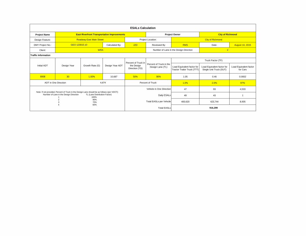
Project Name
Design Feature:
DMY Project No.: Calculated By: JZD Reviewed By RMS Date: August 10, 2015
Client:
8008 30 1.00% 10,687 50% 90% 1.05 0.46 0.0002
1.0% 2.0% 97%
47 93 4,533
49 43 1
483,620 423,744 8,935
Total EASLs
East Riverfront Transportation Improvements Project Owner City of Richmond
Total EASLs per Vehcile
916,299
ADT in One Direction 4,674
Number of Lane in the Design DirectionWRA
Growth Rate (G)Percent of Truck in
the Design Direction (TD)
Percent of Truck in the Design Lane (TL)
Truck Factor (TF)
Design Year Design Year ADT
2
ESALs Calculation
Daily ESALs
Percent of Truck
Load Equivalent factor for Tractor Trailor Truck (TTT)
Load Equivalent factor for Single Unit Truck (SUT)
Load Equivalent factor for Cars
Vehicle in One Direction
GEO 123015.10
Roadway-East Main Street Project Location: City of Richmond
Note: If not provided, Percent of Truck in the Design Lane should be as follows (per VDOT):Number of Lane in the Design Direction TL (Lane Distribution Factor)
1 100%2 90% 3 70%4 60%
Traffic Information
Initial ADT

Layer Str. Coeff. Dar.Coff.1 0.44 1 220 lbs/SY2 0.44 1 220 lbs/SY3 0.44 1 440 lbs/SY4 0.12 15 0.10 1
TOTAL Inches
Load Equivalent factor for Cars
Annual Traffic Growth Rate (%): 1.00%
Total Calculated ESALs: 916,299
Percent of Trucks in Design Direction: 50%
Percent of Trucks in Design Lane: 90%
0.0002
1.05
0.46
Load Equivalent factor for Tractor Trailor Truck (TTT)
Load Equivalent factor for Single Unit Truck (SUT)
Two-Way Daily Traffic (AADT): 8008
Heavy Vehicle % (FHWA Class 5 or greater): 3.0%
Number of Lanes in Design Direction: 2
18.0 4.72
ESAL Calculation
Performance Period (years): 30
VDOT 21B 10.0 1.20Selected Matl CBR-30 0.0 0.00
IM-19.0A 2.0 0.88BM-25.0A 4.0 1.76
Material Thickness (in) Application Calculated SNSM-12.5D 2.0 0.88
3.95Calculated Design Structural Number (SN)
Specified Layer Design
Roadbed Soil Resilent Modulus (PSI) 5700Stage Construction 1
850.49
Initial Serviceability:Terminal Serviceability:Reliablity Level (%):Overall Standard Deviation:
916,29918-kip ESALs Over Initial Period:4.22.9
Flexible Structureal Design Module Data
GEO 123015.10East Riverfront Transportation Improvements
City of Richmond
Roadway-East Main Street
Roadway-East Main Street
1993 AASHTO Pavement Design
Flexible Pavement Design
Related Documents