INSTALLATION GUIDE EX FRONT BUMPER & RX FRONT BUMPER JL WRANGLER & GLADIATOR AEV30446AA Last Updated: 10/08/21 PLEASE READ ENTIRELY BEFORE YOU START To guarantee a quality installation, we recommend reading these instructions thoroughly before beginning any work. These instructions assume a certain amount of mechanical ability and are not written nor intended for someone not familiar with auto repair. TABLE OF CONTENTS I. Vehicle Preparation II. Prepare Main Structural Weldment III. Install Winch Mount (Optional) IV. Install Main Structure to Vehicle V. Install Center Stamping VI. RX “Stubby” Corner Installation VII. EX “Full Width” Corner Installation VIII. Instal Front Skid Plate (Optional) IX. Secure Tow Loops X. Install Fog Light Bezels and Step Pads REQUIRED TOOLS Common Hand Tools Allen Drivers T20 Torx Driver Torque Wrench (recommended) Telescoping Magnet Slipper/Pry Bar (to aid in hole alignment) Optional: M8-1.25, M10-1.5, M12-1.75 thread taps

Welcome message from author
This document is posted to help you gain knowledge. Please leave a comment to let me know what you think about it! Share it to your friends and learn new things together.
Transcript
INS
TA
LLA
TIO
N G
UID
E
EX FRONT BUMPER &RX FRONT BUMPER
JL WRANGLER & GLADIATOR
AEV30446AALast Updated: 10/08/21
PLEASE READ ENTIRELY BEFORE YOU STARTTo guarantee a quality installation, we recommend reading these instructions thoroughly before beginning any work. These instructions assume a certain amount of mechanical ability and are not written nor intended for someone not familiar with auto repair.
TABLE OF CONTENTS
I. Vehicle Preparation
II. Prepare Main Structural Weldment
III. Install Winch Mount (Optional)
IV. Install Main Structure to Vehicle
V. Install Center Stamping
VI. RX “Stubby” Corner Installation
VII. EX “Full Width” Corner Installation
VIII. Instal Front Skid Plate (Optional)
IX. Secure Tow Loops
X. Install Fog Light Bezels and Step Pads
REQUIRED TOOLS
Common Hand Tools
Allen Drivers
T20 Torx Driver
Torque Wrench (recommended)
Telescoping Magnet
Slipper/Pry Bar (to aid in hole alignment)
Optional: M8-1.25, M10-1.5, M12-1.75 thread taps

EX
FR
ON
T B
UM
PE
RJL
WR
AN
GLE
R &
GLA
DIA
TO
R

EX
FR
ON
T B
UM
PE
RJL
WR
AN
GLE
R &
GLA
DIA
TO
R

RX
FR
ON
T B
UM
PE
RJL
WR
AN
GLE
R &
GLA
DIA
TO
R

RX
FR
ON
T B
UM
PE
RJL
WR
AN
GLE
R &
GLA
DIA
TO
R
ITEM
N
O.
Part
No
DES
CRIP
TIO
NQ
TY.
1A
JLB0
116A
AFA
IRLE
AD
WEL
DM
ENT
1
2A
JLB1
000A
BCE
NTE
R ST
AM
PIN
G1
3A
JLB1
002A
ASK
IDPL
ATE
1
4A
JLB1
004A
ARH
SKI
D A
TTA
CHIN
G B
RKT
1
5A
JLB1
005A
ALH
SKI
D A
TTA
CHIN
G B
RKT
1
6A
JLB1
030A
BRH
STU
BBY
CORN
ER S
TAM
PIN
G1
7A
JLB1
031A
BLH
STU
BBY
CORN
ER S
TAM
PIN
G1
8A
JLB1
026A
BRH
TU
BE C
LOSE
OU
T1
9A
JLB1
027A
BLH
TU
BE C
LOSE
OU
T1
10A
JLB1
104A
ATU
BE C
OVE
R1
1160
4062
04A
ABA
DG
E1
12A
EV93
030A
AM
10 X
1.5
HEX
BO
DY
RIVN
UT
4
13A
EV98
006A
AM
10 F
LAT
WA
SHER
4
14A
JLB1
061A
ATO
W L
OO
P SP
ACE
R2
15A
JLB0
104A
ARH
TO
W L
OO
P1
16A
JLB0
105A
ALH
TO
W L
OO
P1
17A
EV98
007A
BM
8 FL
AT
WA
SHER
18
18A
EV91
018A
BM
8 X
1.25
X 2
5 BH
CS18
1995
210A
190
M8
X 1.
25 U
-NU
T6
20O
EM P
ART
SFR
AM
E H
ORN
REI
NF
4
21A
JLB1
089A
ALW
R TO
W L
OO
P SP
ACE
R PL
ATE
2
22A
JLB1
088A
AU
PR T
OW
LO
OP
SPA
CER
PLA
TE2
23A
JLB1
077A
ATO
W L
OO
P CR
USH
SLE
EVE
4
24A
EV91
025A
AM
10 X
1.5
X25
HCS
2
25A
EV98
004A
CM
12 F
LAT
WA
SHER
14
ITEM
N
O.
Part
No
DES
CRIP
TIO
NQ
TY.
26A
EV91
151A
AM
12 X
1.7
5 X
150
HCS
2
27A
EV91
144A
AM
10 X
1.5
X 4
5 H
CS2
28A
JLB0
120A
AW
INCH
MO
UN
T1
29A
JLB1
034A
ARH
WIN
CH M
OU
NT
REIN
F1
30A
JLB1
035A
ALH
WIN
CH M
OU
NT
REIN
F1
31A
EV93
002A
BM
10 X
1.5
FLA
NG
E N
UT
4
32A
EV93
003A
BM
8 X
1.25
FLA
NG
E N
UT
4
33A
EV93
001A
BM
12 X
1.7
5 FL
AN
GE
NU
T10
34A
EV91
002A
EM
12 X
1.7
5 X
50 B
HCS
2
35A
EV91
001A
BM
12 X
1.7
5 X
35 B
HCS
2
3611
5485
80M
4.2
X 1.
41 U
-NU
T4
37A
JLB1
032A
ARH
FO
G B
EZEL
1
38A
JLB1
033A
ALH
FO
G B
EZEL
1
39A
EV91
154A
AN
O. 8
X .7
5" R
OU
ND
ED H
EAD
SH
EET
MET
AL
SCRE
W4
40A
JLB1
023A
ALH
FO
G L
IGH
T BR
ACK
ET1
41A
JLB1
022A
ARH
FO
G L
IGH
T BR
ACK
ET1
4294
810A
100
NO
. 8 C
LIP
ON
NU
T6
43A
EV91
163A
AM
6 X
1.0
X 25
TH
REA
DED
STU
D4
44A
EV91
056A
AM
6 FE
ND
ER W
ASH
ER4
45A
EV93
027A
AM
6 X
1.0
FLA
NG
E N
UT
4
46A
EV91
016A
AM
12 X
1.7
5 X
35 H
CS8
47A
JLB1
090A
AW
INCH
MO
UN
T RE
INF
SPA
CER
2
48A
JLB1
072A
BRH
STE
P PA
D1
49A
JLB1
073A
BLH
STE
P PA
D1
5011
5887
40M
10 X
1.5
X 4
0 FL
AN
GE
BOLT
8
51A
JLB0
052A
ACA
MER
A M
OU
NT
ASS
EMBL
Y1
1
A M E R I C A N E X P E D I T I O N V E H I C L E S
I. VEHICLE PREPARATIONNOTE: The factory bumper and air dam removal will vary slightly depending on version. There are multiple different plastic as well as steel bumpers and skidplates offered. the AEV bumper is designed to work with the AEV high-clearance front skidplate and will not fit with factory steel skidplate.
1. Remove Factory Air Dam or Skid Plate
A. Unbolt the skidplate or air dam from the bottom of the factory bumper and compatibility beam. These will not be reused with AEV bumper or skidplate.
B. Unbolt the stamped support/mounting brackets from the compatibility beams. These components will not be reused.
2. Remove OEM Front Bumper
A. Disconnect the bumper wiring harness from the outside of the passenger front frame horn.
B. Remove the eight nuts at back-side of the bumper holding the bumper and tow hook assembly to the frame.
C. Carefully remove the entire bumper assembly, being sure there are no wires or other components snagged during removal.
D. Save the 4 tow hook support brackets attached to the frame The brackets will be reused with the AEV bumper along with the inner M10 mounting bolts.
E. Remove the factory fog lights (save hardware) and bumper harness from the factory bumper assembly, they will be reused with AEV bumper.
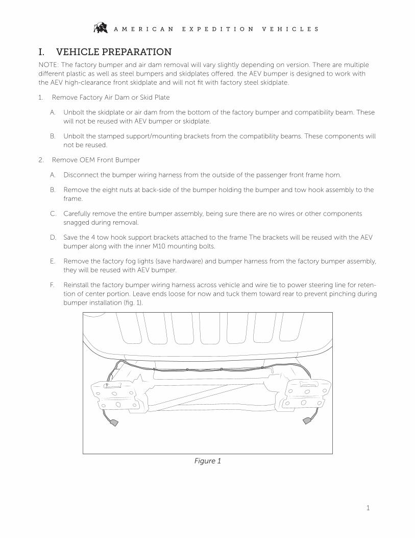
F. Reinstall the factory bumper wiring harness across vehicle and wire tie to power steering line for reten-tion of center portion. Leave ends loose for now and tuck them toward rear to prevent pinching during bumper installation (fig. 1).
Figure 1
2
A M E R I C A N E X P E D I T I O N V E H I C L E S
II. PREPARE MAIN STRUCTURAL WELDMENT1. Reinstall factory fog lights
Install OEM fog lights to inside of main weldment using provided threaded inserts, u-nuts, and factory hardware. Place masking or painters tape over the lenses, otherwise they will get damaged during bum-per corner installation.
A. Sport Halogen:
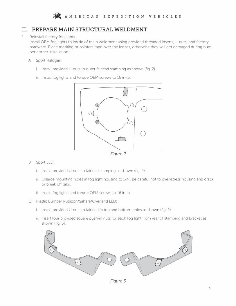
i. Install provided U-nuts to outer fairlead stamping as shown (fig. 2).
ii. Install fog lights and torque OEM screws to 16 in-lb.
Figure 2
B. Sport LED:
i. Install provided U-nuts to fairlead stamping as shown (fig. 2).
ii. Enlarge mounting holes in fog light housing to 1/4”. Be careful not to over-stress housing and crack or break off tabs.
iii. Install fog lights and torque OEM screws to 16 in-lb.
C. Plastic Bumper Rubicon/Sahara/Overland LED:
i. Install provided U-nuts to fairlead in top and bottom holes as shown (fig. 2)
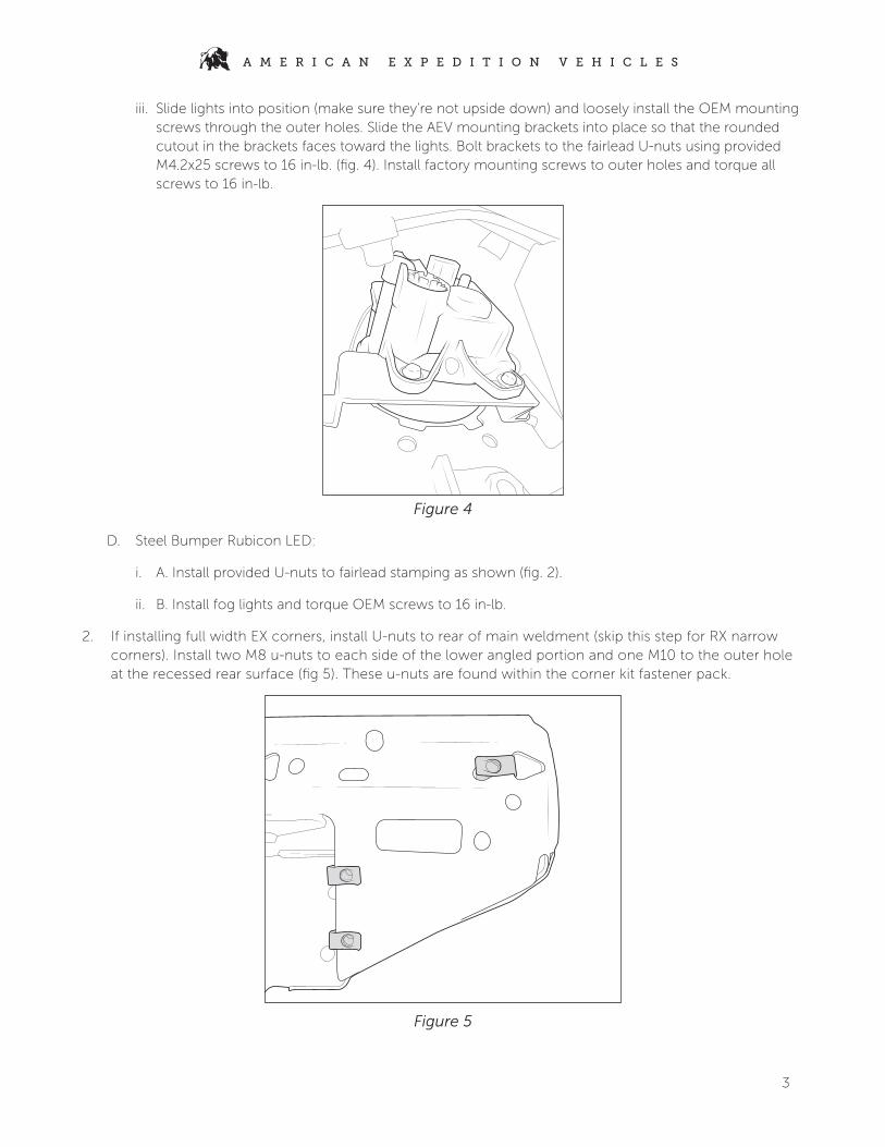
ii. Insert four provided square push-in nuts for each fog light from rear of stamping and bracket as shown (fig. 3).
Figure 3
3
A M E R I C A N E X P E D I T I O N V E H I C L E S
iii. Slide lights into position (make sure they’re not upside down) and loosely install the OEM mounting screws through the outer holes. Slide the AEV mounting brackets into place so that the rounded cutout in the brackets faces toward the lights. Bolt brackets to the fairlead U-nuts using provided M4.2x25 screws to 16 in-lb. (fig. 4). Install factory mounting screws to outer holes and torque all screws to 16 in-lb.
Figure 4
D. Steel Bumper Rubicon LED:
i. A. Install provided U-nuts to fairlead stamping as shown (fig. 2).
ii. B. Install fog lights and torque OEM screws to 16 in-lb.
2. If installing full width EX corners, install U-nuts to rear of main weldment (skip this step for RX narrow corners). Install two M8 u-nuts to each side of the lower angled portion and one M10 to the outer hole at the recessed rear surface (fig 5). These u-nuts are found within the corner kit fastener pack.
Figure 5
4
A M E R I C A N E X P E D I T I O N V E H I C L E S
3. OPTIONAL: AEV recommends running a tap through all the threaded holes on the weldment to remove any excess coating in threads and ease bolt installation in later steps. Thread sizes are M8-1.25, M10-1.5, and M12-1.75.
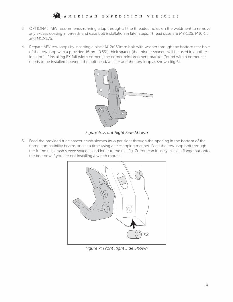
4. Prepare AEV tow loops by inserting a black M12x150mm bolt with washer through the bottom rear hole of the tow loop with a provided 15mm (0.59”) thick spacer (the thinner spacers will be used in another location). If installing EX full width corners, the corner reinforcement bracket (found within corner kit) needs to be installed between the bolt head/washer and the tow loop as shown (fig 6).
Figure 6: Front Right Side Shown
5. Feed the provided tube spacer crush sleeves (two per side) through the opening in the bottom of the frame compatibility beams one at a time using a telescoping magnet. Feed the tow loop bolt through the frame rail, crush sleeve spacers, and inner frame rail (fig. 7). You can loosely install a flange nut onto the bolt now if you are not installing a winch mount.
X2
Figure 7: Front Right Side Shown

5
A M E R I C A N E X P E D I T I O N V E H I C L E S
III. INSTALL WINCH MOUNT (OPTIONAL)1. Install M10 riv-nuts using provided tool into the two hex shaped holes on the inboard side of each com-
patibility beam (fig. 8). To use rivnut tool, run provided bolt through the washer and coupler, then thread on rivnut until snug. Flanged end of rivnut should sit against the coupler. Place rivnut into desired hole, hold coupler stationary with a wrench, and tighten the bolt to 31 ft-lb. Remove the bolt and coupler to make sure the rivnut has full compressed. NOTE: Depending on factory bumper configuration, some vehicles may already have riv-nuts in these locations.
Figure 8
2. Reinstall factory tow hook support brackets to inside of frame rails. Bolt to front frame flange using one M12x35mm bolt and washer from the front and flange nut on the rear. Hardware only needs to be snug to hold bracket in position, it will be removed later (fig. 9).
Figure 9

6
A M E R I C A N E X P E D I T I O N V E H I C L E S
3. Install the winch plate to the frame in the orientation shown (fig. 11). Use supplied M10x40mm bolts to loosely bolt winch plate and reinforcement brackets into the frame weld nuts.
Figure 11
4. Loosely install winch support brackets to the riv-nuts using provided M10x40mm flange bolts and loosely install flange nuts to the M12 tow loop bolts. If installing AEV Front Bumper Skidplate, install the provided mounting brackets between winch support brackets and compatibility beam (fig. 12). NOTE: If installing both the winch mount and front skidplate, there will be four leftover M10x40mm flange bolts and rivnuts.
Figure 12: With Skidplate Bracket (left) Without Skidplate Bracket (right)

7
A M E R I C A N E X P E D I T I O N V E H I C L E S
5. Bolt winch plate in place to the support brackets using the provided M10x40mm bolts and nuts. Bolts should be inserted from the top down. Hand tighten, do not fully torque (fig. 13). NOTE: Due to frame width variations, some installations may need the winch plate mounting tabs bent inward slightly to ease installation. This can be done by placing one end on the ground and hitting the other with a deadblow hammer. Use caution to not damage the coating. NOTE: If installing AEV Skidplate Light Bar Kit, install provided brackets to the rear bolts tying the winch plate to the support brackets. Light bar brackets should mount with long leg down, inboard, and toward rear of vehicle. Install light bar and hand tighten to hold brackets in proper position (fig. 14).
Figure 13 Figure 14
6. Slide winch plate forward so bolts are bottomed against rear of slots on side mounts. Hand tighten all the M10 hardware between winch support brackets and frame riv-nuts. This will set the position of the winch plate and brackets. Once all are hand tight, torque the winch plate to reinforcement bracket hardware to 30 ft-lb, then torque the winch plate side bolts into the frame to 30 ft-lb. Remove the M12 hardware temporarily holding the frame reinforcement brackets to the front frame flanges. This will be reused momentarily. NOTE: If installing skidplate light bar kit, shift the brackets as far rearward as possible before tightening winch support bolts. On models with electronic sway bar disconnect it will sit tight against the isola-tor bushing. Tighten the lightbar mounting hardware to manufacturer spec centered in vertical slot on mounting brackets. If using a light bar other than the AEV recommendation, additional adjustments may be needed during skidplate installation
8
A M E R I C A N E X P E D I T I O N V E H I C L E S
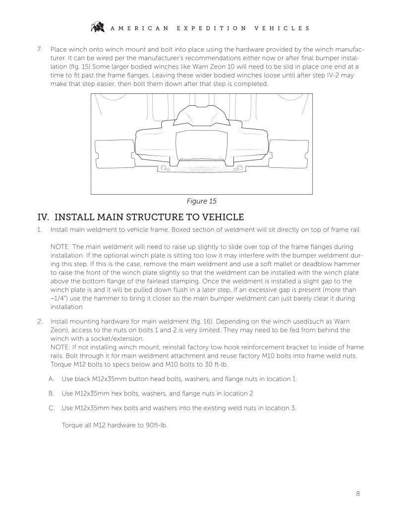
7. Place winch onto winch mount and bolt into place using the hardware provided by the winch manufac-turer. It can be wired per the manufacturer’s recommendations either now or after final bumper instal-lation (fig. 15) Some larger bodied winches like Warn Zeon 10 will need to be slid in place one end at a time to fit past the frame flanges. Leaving these wider bodied winches loose until after step IV-2 may make that step easier, then bolt them down after that step is completed.
Figure 15
IV. INSTALL MAIN STRUCTURE TO VEHICLE1. Install main weldment to vehicle frame. Boxed section of weldment will sit directly on top of frame rail.
NOTE: The main weldment will need to raise up slightly to slide over top of the frame flanges during installation. If the optional winch plate is sitting too low it may interfere with the bumper weldment dur-ing this step. If this is the case, remove the main weldment and use a soft mallet or deadblow hammer to raise the front of the winch plate slightly so that the weldment can be installed with the winch plate above the bottom flange of the fairlead stamping. Once the weldment is installed a slight gap to the winch plate is and it will be pulled down flush in a later step. If an excessive gap is present (more than ~1/4”) use the hammer to bring it closer so the main bumper weldment can just barely clear it during installation
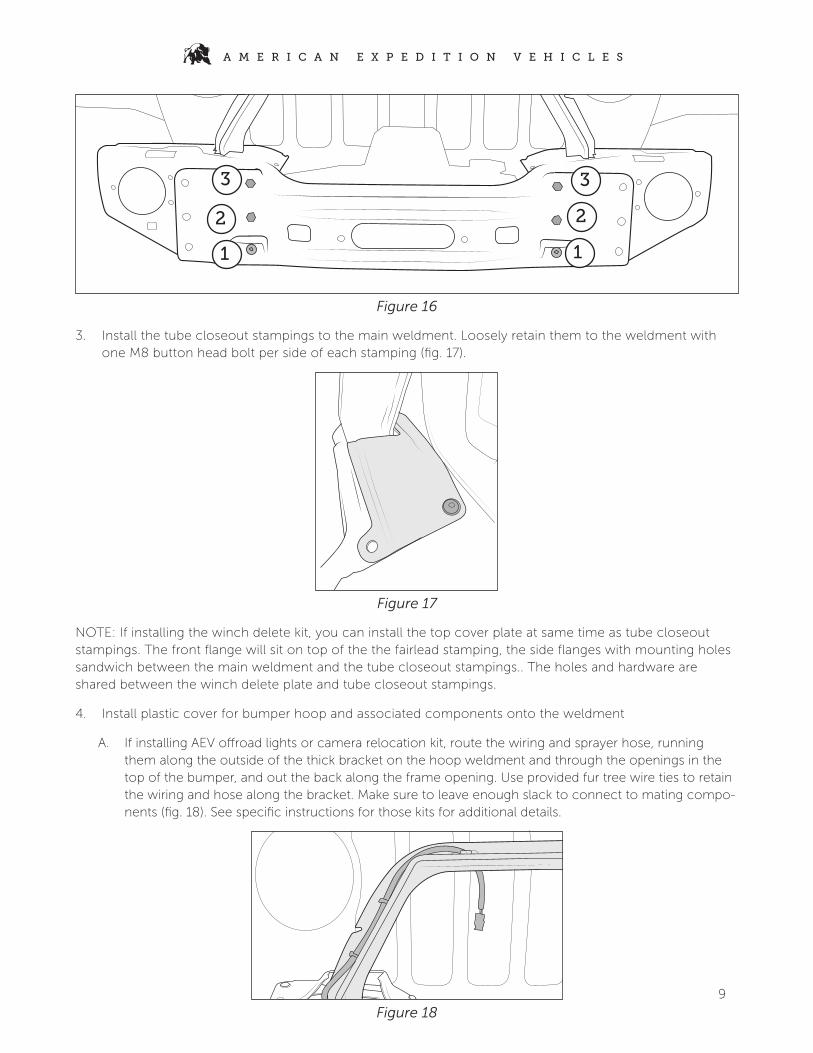
2. Install mounting hardware for main weldment (fig. 16). Depending on the winch used(such as Warn Zeon), access to the nuts on bolts 1 and 2 is very limited. They may need to be fed from behind the winch with a socket/extension. NOTE: If not installing winch mount, reinstall factory tow hook reinforcement bracket to inside of frame rails. Bolt through it for main weldment attachment and reuse factory M10 bolts into frame weld nuts. Torque M12 bolts to specs below and M10 bolts to 30 ft-lb.
A. Use black M12x35mm button head bolts, washers, and flange nuts in location 1.
B. Use M12x35mm hex bolts, washers, and flange nuts in location 2
C. Use M12x35mm hex bolts and washers into the existing weld nuts in location 3. Torque all M12 hardware to 90ft-lb.
9
A M E R I C A N E X P E D I T I O N V E H I C L E S
1 1
22
3 3
Figure 16
3. Install the tube closeout stampings to the main weldment. Loosely retain them to the weldment with one M8 button head bolt per side of each stamping (fig. 17).
Figure 17
NOTE: If installing the winch delete kit, you can install the top cover plate at same time as tube closeout stampings. The front flange will sit on top of the the fairlead stamping, the side flanges with mounting holes sandwich between the main weldment and the tube closeout stampings.. The holes and hardware are shared between the winch delete plate and tube closeout stampings.
4. Install plastic cover for bumper hoop and associated components onto the weldment
A. If installing AEV offroad lights or camera relocation kit, route the wiring and sprayer hose, running them along the outside of the thick bracket on the hoop weldment and through the openings in the top of the bumper, and out the back along the frame opening. Use provided fur tree wire ties to retain the wiring and hose along the bracket. Make sure to leave enough slack to connect to mating compo-nents (fig. 18). See specific instructions for those kits for additional details.
Figure 18
10
A M E R I C A N E X P E D I T I O N V E H I C L E S
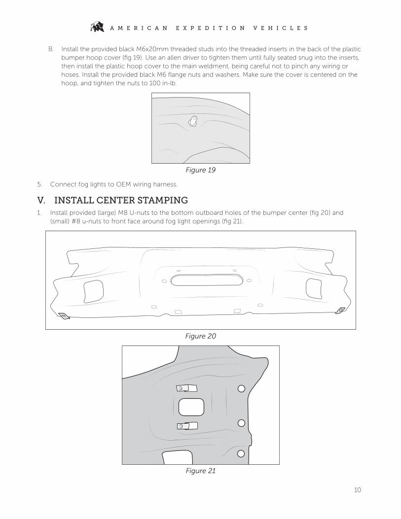
B. Install the provided black M6x20mm threaded studs into the threaded inserts in the back of the plastic bumper hoop cover (fig 19). Use an allen driver to tighten them until fully seated snug into the inserts, then install the plastic hoop cover to the main weldment, being careful not to pinch any wiring or hoses. Install the provided black M6 flange nuts and washers. Make sure the cover is centered on the hoop, and tighten the nuts to 100 in-lb.
Figure 19
5. Connect fog lights to OEM wiring harness.
V. INSTALL CENTER STAMPING1. Install provided (large) M8 U-nuts to the bottom outboard holes of the bumper center (fig 20) and
(small) #8 u-nuts to front face around fog light openings (fig 21).
Figure 20
Figure 21
11
A M E R I C A N E X P E D I T I O N V E H I C L E S
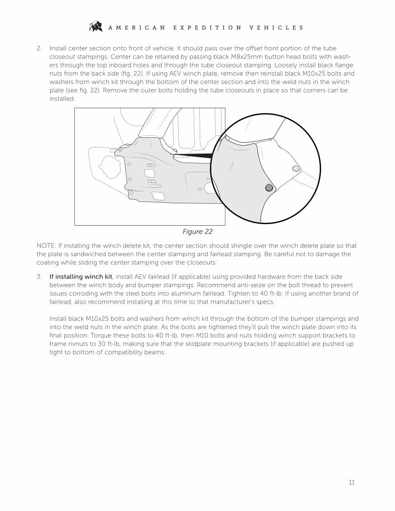
2. Install center section onto front of vehicle. It should pass over the offset front portion of the tube closeout stampings. Center can be retained by passing black M8x25mm button head bolts with wash-ers through the top inboard holes and through the tube closeout stamping. Loosely install black flange nuts from the back side (fig. 22). If using AEV winch plate, remove then reinstall black M10x25 bolts and washers from winch kit through the bottom of the center section and into the weld nuts in the winch plate (see fig. 22). Remove the outer bolts holding the tube closeouts in place so that corners can be installed.
Figure 22
NOTE: If installing the winch delete kit, the center section should shingle over the winch delete plate so that the plate is sandwiched between the center stamping and fairlead stamping. Be careful not to damage the coating while sliding the center stamping over the closeouts.
3. If installing winch kit, install AEV fairlead (if applicable) using provided hardware from the back side between the winch body and bumper stampings. Recommend anti-seize on the bolt thread to prevent issues corroding with the steel bolts into aluminum fairlead. Tighten to 40 ft-lb. If using another brand of fairlead, also recommend installing at this time to that manufacturer’s specs. Install black M10x25 bolts and washers from winch kit through the bottom of the bumper stampings and into the weld nuts in the winch plate. As the bolts are tightened they’ll pull the winch plate down into its final position. Torque these bolts to 40 ft-lb, then M10 bolts and nuts holding winch support brackets to frame rivnuts to 30 ft-lb, making sure that the skidplate mounting brackets (if applicable) are pushed up tight to bottom of compatibility beams.
12
A M E R I C A N E X P E D I T I O N V E H I C L E S
VI. RX CORNER INSTALLATION1. Slide OEM frame reinforcement bracket into place between outside of frame and main bumper weld-
ment. Temporarily retain with factory M10 bolts into weld nut on the side of the frame.
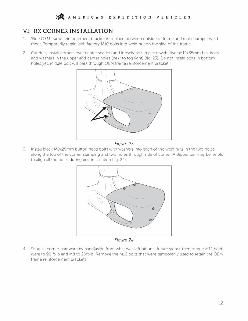
2. Carefully install corners over center section and loosely bolt in place with silver M12x35mm hex bolts and washers in the upper and center holes (next to fog light) (fig. 23). Do not install bolts in bottom holes yet. Middle bolt will pass through OEM frame reinforcement bracket.
Figure 233. Install black M8x25mm button head bolts with washers into each of the weld nuts in the two holes
along the top of the corner stamping and two holes through side of corner. A slipper bar may be helpful to align all the holes during bolt installation (fig. 24).
Figure 24
4. Snug all corner hardware by hand(aside from what was left off until future steps), then torque M12 hard-ware to 90 ft-lb and M8 to 20ft-lb. Remove the M10 bolts that were temporarily used to retain the OEM frame reinforcement brackets

13
A M E R I C A N E X P E D I T I O N V E H I C L E S
VII. EX CORNER INSTALLATION (STANDARD & HIGHLINE)
1. Carefully slide corner assemblies in from the side of the bumper, being careful not to damage the fog light lenses as the edge slides across it (this is where the masking tape is critical). Corner outer stamping will shell over center section. Back side of corner weldment will fit tightly against the main weldment, so an extra set of hands may be helpful to guide it over the M8 u-nuts at the rear. A slipper bar can also be helpful to get all the holes aligned (fig. 25). Be careful not to push the corner on too far and don’t lift the outer end during installation. This can cause the sharp edge on the corner stamping to damage the coating on the mating pieces and lead to premature corrosion if installed improperly. NOTE: Make sure corner reinforcement brackets are flipped up so they can be rotated forward to bolt in place in Step IX.4. If they’re hanging down when corner is installed they’ll need to be removed to get into proper position..
Figure 252. Loosely bolt in place beginning with the weld nut locations; rear inner hole with M10x30mm bolt and
washer from corner kit (fig. 26), then front upper hole with silver M12x35mm hex bolts and washers (fig. 27), then top two holes with black M8x25mm button head bolts and washers (fig. 28).
Figure 26 Figure 27

14
A M E R I C A N E X P E D I T I O N V E H I C L E S
Figure 28
3. Slide OEM frame reinforcement bracket into place between outside of frame and main bumper weld-ment/corners. Temporarily retain with factory M10 bolts into weld nut on the side of the frame.
4. Install silver M12x35mm hex bolts and washers to middle hole at front of bumper. Middle bolt will pass through OEM frame reinforcement bracket, then install flange nut from the rear. Install M10x30mm bolt and washer from corner kit to rear outer hole into u-nut. Do not install bolts in front bottom holes yet, or rear inner u-nut locations.
5. Snug all corner hardware by hand (aside from what was left off until future steps), then torque M12 to 90ft-lb, M10 to 40ft-lb, and M8 to 20ft-lb. Remove the M10 bolts that were temporarily used to retain the OEM frame reinforcement brackets.
VIII. INSTALL FRONT SKID PLATE (OPTIONAL)NOTE: If installing the winch delete kit, install the fairlead cover plate BEFORE skidplate. Install so oval shaped offset faces forward through fairlead opening. Install provided button head bolts with washers from the front side. Install nuts on rear of cover plate and torque until snug. Excessive torque could crack the plastic.
1. Install two provided M8 U-nuts to the bottom flange of the center stamping with the smooth surface on the bottom side (the outer u-nuts were already installed for tow loops). Insert until the threaded hole is centered within the hole in the stamping. (fig. 29)
Figure 29
15
A M E R I C A N E X P E D I T I O N V E H I C L E S
2. If you installed the AEV winch mount, skip to step 5. Install M10 riv-nuts using provided tool into the two hex shaped holes on the inboard side of each compatibility beam (see fig. 8). To use riv-nut tool, run provided bolt through the washer and coupler, then thread on riv-nut until snug. Flanged end of riv-nut should sit against the coupler. Place riv-nut into desired hole, hold coupler stationary with a wrench, and tighten the bolt to 31 ft-lb. Remove the bolt and coupler to make sure the riv-nut has full compressed. NOTE: Depending on factory bumper configuration, some vehicles may already have riv-nuts in these locations.
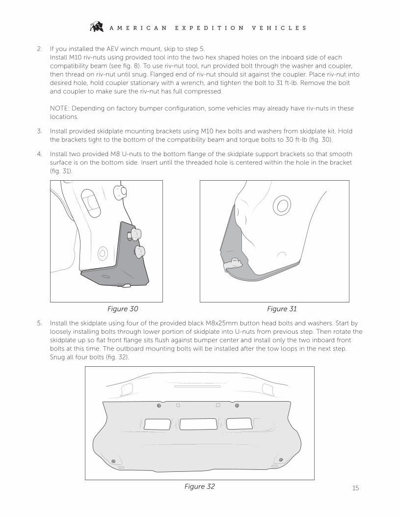
3. Install provided skidplate mounting brackets using M10 hex bolts and washers from skidplate kit. Hold the brackets tight to the bottom of the compatibility beam and torque bolts to 30 ft-lb (fig. 30).
4. Install two provided M8 U-nuts to the bottom flange of the skidplate support brackets so that smooth surface is on the bottom side. Insert until the threaded hole is centered within the hole in the bracket (fig. 31).
X2
Figure 30 Figure 31
5. Install the skidplate using four of the provided black M8x25mm button head bolts and washers. Start by loosely installing bolts through lower portion of skidplate into U-nuts from previous step. Then rotate the skidplate up so flat front flange sits flush against bumper center and install only the two inboard front bolts at this time. The outboard mounting bolts will be installed after the tow loops in the next step. Snug all four bolts (fig. 32).
Figure 32

16
A M E R I C A N E X P E D I T I O N V E H I C L E S
IX. SECURE TOW LOOPS1. Rotate tow loops up into final position. Install black M8x25mm button head bolts with washer through
the lower tab in the tow loop, through the skidplate, and into the center section U-nut. Install black M12x50mm button head bolt and washer through front hole in tow loop, through bumper and rein-forcement bracket, and install flange nut on back side. Torque M12 bolt to 90ft-lb. and M8 bolt to 20ft-lb (fig. 33).
Figure 33
2. Locate the two black M10x45mm hex bolts, washers, and thin 10.7mm (.42”) spacers. If equipped with full width EX corners, rotate the corner reinforcement bracket into position. Begin feeding the M10 bolt and washer through from the outside, and sandwich the spacer between the tow loop and bumper reinforcement bracket. Thread the bolt into the factory weld nut in the frame and tighten until snug. On EX Corners, install M8 bolts and washers fromn corner kit and torque to 20 ft-lb (fig. 34).Torque M10 tow loop bolts to 30 ft-lb (fig. 35). Torque side M12 tow loop hardware to 90ft-lb.
Figure 34
17
A M E R I C A N E X P E D I T I O N V E H I C L E S
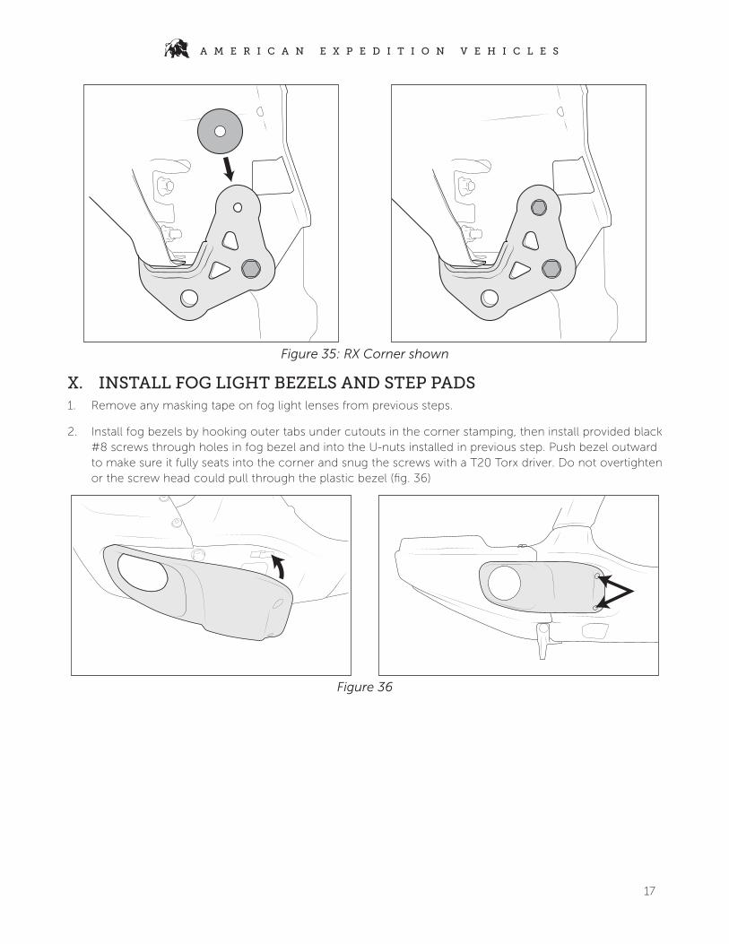
Figure 35: RX Corner shown
X. INSTALL FOG LIGHT BEZELS AND STEP PADS1. Remove any masking tape on fog light lenses from previous steps.
2. Install fog bezels by hooking outer tabs under cutouts in the corner stamping, then install provided black #8 screws through holes in fog bezel and into the U-nuts installed in previous step. Push bezel outward to make sure it fully seats into the corner and snug the screws with a T20 Torx driver. Do not overtighten or the screw head could pull through the plastic bezel (fig. 36)
Figure 36

18
A M E R I C A N E X P E D I T I O N V E H I C L E S
3. Make sure top surface of bumper is clean and dry and install provided adhesive-backed foam step pads as shown (if desired). Be sure to hold in place with strong pressure for at least 30 seconds (fig. 37)
Figure 37
4. If installing other accessories such as camera relocation kit or AEV 7000 series lights, complete those installations now.
Related Documents


![Integrated AV Amplifier - pdf.crse.compdf.crse.com/manuals/3856168111.pdf · 6EN Getting Started Hookups Front speakers Front speaker (R) Front speaker (L) Amplifier} ] FRONT SPEAKERS](https://static.cupdf.com/doc/110x72/5b15a6767f8b9a332f8d45d5/integrated-av-amplifier-pdfcrse-6en-getting-started-hookups-front-speakers.jpg)