Dual-Stage Model Predictive Control for Flying Capacitor Converters Pablo Lezana, Margarita Norambuena Departamento de Ingeniería Eléctrica Universidad Técnica Federico Santa María Valparaíso, Chile 239-0123 emails: [email protected] [email protected] Ricardo P. Aguilera, Daniel E. Quevedo School of Electrical Engineering & Computer Science The University of Newcastle NSW, Australia e-mails: {raguilera, dquevedo}@ieee.org Abstract—In this work, we propose a dual-stage control ap- proach for a three-phase four-level Flying Capacitor Converter. The key idea of this proposal is to combine two control strategies to govern this converter. Thus, if the system state (output currents and floating voltages) is far from the desired reference, Finite- Control-Set Model Predictive Control is used to quickly lead the system towards the reference. Once the system state reaches a neighborhood of the reference, the propose control strategy switches to a PWM-based linear controller to finally achieve the desired reference in a gentle manner. I. I NTRODUCTION In last decade, in the field of power electronics, several works have proposed the use of Finite-Control-Set Model Predictive Control (FCS-MPC) to govern several classes of power converters and electrical drives [1]–[3]. Main advantages of this control technique are its conceptual simplicity, simple treatment of non-linearities, fast dynamic response, and its capability of control multiple variables with a single structure. Since power switches are explicitly taken into account in the optimal problem, FCS-MPC does not required a modulation stage. Unfortunately, this predictive control strategy presents some significant drawbacks such as uneven switching distri- bution, wide spread signals spectra, and steady-state error [4]. Most of this issues can be overcome by including them as control targets in the cost function [4], [5]. Nevertheless, this decrements the quality of the main variables since there exists a trade off among the individual control targets [6], [7]. In [8], a switched model predictive control scheme is proposed, combining the excellent dynamic response and the multi-objective capability of FCS-MPC with the good steady- state performance of the Explicit MPC, which requires a PWM to generate the switching signals. When the overall system deviation reaches a high level, i.e., the system state is far from the desired reference, the FCS-MPC strategy is activated. Thus, the system state is quickly led to a terminal region. Once this region is reached (low value of the system deviation) the controller switches to the Explicit MPC mode. This control scheme is proposed for a single-phase four-level Flying Capacitor (FC) converter, which is a non-linear time- invariant system with three variables to be controlled: the output current and two floating capacitor voltages [9]. The results presented in [8] shows a good performance in steady- state with a fixed and evenly distributed switching frequency in all semiconductors, a well defined output current spectrum, and fast responses under output reference steps and voltage perturbations. Based on the same concept, in this work, a dual-stage control scheme, which combines a classical linear controller (PI, resonant, etc.) with FCS-MPC, is proposed. The main advantage of this structure over the one proposed in [8] is the robustness that linear controllers present under parameters variations and/or estimation errors. Nonetheless, in this case, the switch from the FCS-MPC to the linear controller, once the terminal region is reached, is more complicated. The linear controller must be properly initialized in order to avoid oscillations or bumps associated with controller switching. To do this, the FCS-MPC operation is interpreted by the linear controller as a saturated actuation, which is feedbacked in an anti-windup structure yielding, thus, a gentle bump-less transition. Results obtained with this proposed scheme are compared with those obtained with the approached proposed in [8] in a four-level three-phase FC converter, showing similar dynamics between both methods, bump-less control transitions, and a robust behavior of the proposed control technique when un- certainties are present. II. THE FLYING CAPACITOR CONVERTER The FC converter is a multilevel topology early introduced in [9]. Fig. 1(a) shows the topology for a three-cell single- phase FC converter, which is composed by the tandem con- nection of three basic units called cells. Each cell requires a capacitor and two power switches, which must be operated complementary. In most works, the capacitor voltages ratio is set as v x1 : v x2 : v x3 =1:2:3, with x ∈{a, b, c}. When this condition is reached, the converter generates a four- level voltage waveform between the output terminal x and the inverter neutral point N . Other voltage ratios have been proposed in literature [2], [10], [11]; however, the standard 1:2:3 ratio presents the advantage of obtaining an evenly spread voltage stress among the power switches. Additionally, this standard ratio can be naturally achieved with a simple Phase- Shifted PWM (PS-PWM) strategy, i.e., in an open-loop manner [12], [13]. The general mathematical relationships for the three-cell FC

Welcome message from author
This document is posted to help you gain knowledge. Please leave a comment to let me know what you think about it! Share it to your friends and learn new things together.
Transcript

Dual-Stage Model Predictive Control for FlyingCapacitor Converters
Pablo Lezana, Margarita NorambuenaDepartamento de Ingeniería Eléctrica
Universidad Técnica Federico Santa MaríaValparaíso, Chile 239-0123
emails: [email protected]@alumnos.usm.cl
Ricardo P. Aguilera, Daniel E. QuevedoSchool of Electrical Engineering & Computer Science
The University of NewcastleNSW, Australia
e-mails: raguilera, [email protected]
Abstract—In this work, we propose a dual-stage control ap-proach for a three-phase four-level Flying Capacitor Converter.The key idea of this proposal is to combine two control strategiesto govern this converter. Thus, if the system state (output currentsand floating voltages) is far from the desired reference, Finite-Control-Set Model Predictive Control is used to quickly leadthe system towards the reference. Once the system state reachesa neighborhood of the reference, the propose control strategyswitches to a PWM-based linear controller to finally achieve thedesired reference in a gentle manner.
I. INTRODUCTION
In last decade, in the field of power electronics, severalworks have proposed the use of Finite-Control-Set ModelPredictive Control (FCS-MPC) to govern several classes ofpower converters and electrical drives [1]–[3]. Main advantagesof this control technique are its conceptual simplicity, simpletreatment of non-linearities, fast dynamic response, and itscapability of control multiple variables with a single structure.Since power switches are explicitly taken into account in theoptimal problem, FCS-MPC does not required a modulationstage. Unfortunately, this predictive control strategy presentssome significant drawbacks such as uneven switching distri-bution, wide spread signals spectra, and steady-state error [4].Most of this issues can be overcome by including them ascontrol targets in the cost function [4], [5]. Nevertheless, thisdecrements the quality of the main variables since there existsa trade off among the individual control targets [6], [7].
In [8], a switched model predictive control scheme isproposed, combining the excellent dynamic response and themulti-objective capability of FCS-MPC with the good steady-state performance of the Explicit MPC, which requires aPWM to generate the switching signals. When the overallsystem deviation reaches a high level, i.e., the system stateis far from the desired reference, the FCS-MPC strategy isactivated. Thus, the system state is quickly led to a terminalregion. Once this region is reached (low value of the systemdeviation) the controller switches to the Explicit MPC mode.This control scheme is proposed for a single-phase four-levelFlying Capacitor (FC) converter, which is a non-linear time-invariant system with three variables to be controlled: theoutput current and two floating capacitor voltages [9]. Theresults presented in [8] shows a good performance in steady-state with a fixed and evenly distributed switching frequencyin all semiconductors, a well defined output current spectrum,
and fast responses under output reference steps and voltageperturbations.
Based on the same concept, in this work, a dual-stagecontrol scheme, which combines a classical linear controller(PI, resonant, etc.) with FCS-MPC, is proposed. The mainadvantage of this structure over the one proposed in [8] isthe robustness that linear controllers present under parametersvariations and/or estimation errors. Nonetheless, in this case,the switch from the FCS-MPC to the linear controller, oncethe terminal region is reached, is more complicated. Thelinear controller must be properly initialized in order to avoidoscillations or bumps associated with controller switching. Todo this, the FCS-MPC operation is interpreted by the linearcontroller as a saturated actuation, which is feedbacked inan anti-windup structure yielding, thus, a gentle bump-lesstransition.
Results obtained with this proposed scheme are comparedwith those obtained with the approached proposed in [8] in afour-level three-phase FC converter, showing similar dynamicsbetween both methods, bump-less control transitions, and arobust behavior of the proposed control technique when un-certainties are present.
II. THE FLYING CAPACITOR CONVERTER
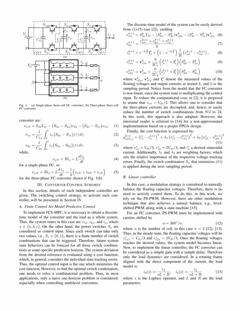
The FC converter is a multilevel topology early introducedin [9]. Fig. 1(a) shows the topology for a three-cell single-phase FC converter, which is composed by the tandem con-nection of three basic units called cells. Each cell requires acapacitor and two power switches, which must be operatedcomplementary. In most works, the capacitor voltages ratiois set as vx1 : vx2 : vx3 = 1 : 2 : 3, with x ∈ a, b, c.When this condition is reached, the converter generates a four-level voltage waveform between the output terminal x andthe inverter neutral point N . Other voltage ratios have beenproposed in literature [2], [10], [11]; however, the standard1:2:3 ratio presents the advantage of obtaining an evenly spreadvoltage stress among the power switches. Additionally, thisstandard ratio can be naturally achieved with a simple Phase-Shifted PWM (PS-PWM) strategy, i.e., in an open-loop manner[12], [13].
The general mathematical relationships for the three-cell FC
x
S3x
Vdc
Cell 3 Cell 1Cell 2
v2x
ix
C3x
i2x
N
C2x C1x
v1x
S3x
S2x
S2x
S1x
S1x
i1x
(a)
(b)
Vdc
N
bib
aia
cic
n
Fig. 1. (a) Single-phase three-cell FC converter; (b) Three-phase three-cellFC converter.
converter are:vxN =S3xVdc −
(S3x − S2x
)v2x −
(S2x − S1x
)v1x, (1)
v1x =1
C1x
∫ t
0
ix(S2x − S1x
)(τ) dτ, (2)
v2x =1
C2x
∫ t
0
ix(S3x − S2x
)(τ) dτ, (3)
while,
vxN = Rix + Ld ixdt
(4)
for a single-phase FC, or
vxN = Rix + Ld ixdt
+1
3
(vaN + vbN + vcN
)(5)
for the three-phase FC converter shown if Fig. 1(b).
III. CONVERTER CONTROL SCHEMES
In this section, details of each independent controller aregiven. The switching control strategy, to activate each con-troller, will be presented in Section IV.
A. Finite Control Set Model Predictive Control
To implement FCS-MPC, it is necessary to obtain a discrete-time model of the converter and the load as a whole system.Thus, the system states in this case are v1x, v2x, and ix, wherex ∈ a, b, c. On the other hand, the power switches Sx areconsidered as control input. Since each switch can take onlytwo values, i.e., Sx ∈ 0, 1, there is a finite number of switchcombinations that can be triggered. Therefore, future systemstate behaviors can be forecast for all those switch combina-tions at some specific prediction horizon. The system deviationfrom the desired reference is evaluated using a cost function,which, in general, considers the individual state tracking errors.Thus, the optimal control input is the one which minimizes thecost function. However, to find the optimal switch combination,one needs to solve a combinatorial problem. Thus, in mostapplications, only a naive one-horizon problem is considered,especially when controlling multilevel converters.
The discrete-time model of the system can be easily derivedfrom (1)-(5) (see [2]), yieldingvk+1xn = Sk
3xVdc − (Sk3x − Sk
2x)vkc2x − (Sk
2x − Sk1x)v
kc1x (6)
vk+1on =
vk+1an + vk+1
bn + vk+1cn
3(7)
ik+1x = e−hR
L ikx +(1− e−hR
L
) 1
R
(vk+1xn − vk+1
on
), (8)
vk+1c1x = vk
c1x +h
2C1
(ik+1x + ikx
)(Sk2x − Sk
1x
)(9)
vk+1c2x = vk
c2x +h
2C2
(ik+1x + ikx
)(Sk3x − Sk
2x
)(10)
where vkc2x, vk
c1x and ikx denote the measured values of thefloating voltages and output currents at instant k, and h is thesampling period. Notice from the model that the FC converteris non-linear, since the system state is multiplicating the controlinput. To reduce the computational cost, in [2], it is proposedto asume that von = Vdc/2. This allows one to consider thatthe three-phase currents are decoupled, and, hence, to easilyreduce the number of switch combinations from 512 to 24.In this work, this approach is also adopted. However, theinterested reader is referred to [14] for a non-approximatedimplementation based on a proper FPGA design.
Finally, the cost function is expressed by:
gk+1x(Sn)
=(i∗x − ik+1
x
)2+ λ1
(v∗c1 − vk+1
c1x
)2+ λ2
(v∗c2 − vk+1
c2x
)2(11)
where v∗c1 = Vdc/3, v∗c2 = 2Vdc/3, and i∗x a desired sinusoidalcurrent. Additionally, λ1 and λ2 are weighting factors, whichsets the relative importance of the respective voltage trackingerrors. Finally, the switch combination Sn that minimizes (11)is applied during the next sampling period.
B. Linear controller
In this case, a modulation strategy is considered to naturallybalance the floating capacitor voltages. Therefore, there is noneed to actively control them. To do this, in this work, werely on the PS-PWM. However, there are other modulationtechnique that also achieves a natural balance, e.g., level-shifted-PWM along with a state-machine [15].
For an FC converter, PS-PWM must be implemented withcarriers shifted by
ϕ = 360/n, (12)where n is the number of cell, in this case n = 3 [12], [13].Thus, in the steady-state, the floating capacitor voltages will bev∗cx1 = Vdc/3 and v∗c2x = 2Vdc/3. Once the floating voltagesreaches the desired values, the system model becomes linear.Now, to implement the linear controller, the FC converter canbe considered as a simple gain with a sample delay. Thereforeonly the load dynamics are considered. In a rotating framealigned with the direct component of the current, the loadmodel is:
id(s) =vd
sL+R, iq(s) =
vqsL+R
(13)
where s is the Laplace operator, and L and R are the loadparameters.

ia
ibic
abc
dq
id
iq
*
*id
iq
abc
dqvd
vq
S3a,S S2 1a a,3
3
3
S3b,S S2 1b b,
S3c,S S2 1c c,
va
vb
vc
+
+
+
+
+
PWM
Fig. 2. Control scheme for lineal controllers.
Since a three-phase sinusoidal current is desired, the ref-erences i∗d and i∗q are constant. Therefore two traditionalProportional Integrative (PI) controllers are used to obtainthe required output converter voltages vd and vq . Then, thesevalues are modulated by using PS-PWM in order to obtainthe firing pulses for the power switches, as shown in Fig. 2.It is important to remark that the floating voltage dynamics,when using PS-PWM, are very slow and can present strongoscillations before reaching the natural balance.
IV. PROPOSED SCHEME
Recently, in [8], the main features of PWM-based lin-ear controllers and FCS-MPC for FC converters have beenhighlighted. In this case, PWM-based linear controllers, insteady-state, offer better performance than FCS-MPC such aszero-error, well defined spectra, and even losses distribution.However, in transients, especially when the floating voltagesare not balanced, FCS-MPC outperforms PWM-based linearcontrollers. In order to exploit both controller advantages, in[8], a switched control strategy based on Explicit-MPC andFCS-MPC is proposed, showing a significant improvement inthe overall operation of the system. Unfortunately, to achieve azero steady-state error when using Explicit-MPC, accurate sys-tem parameter values are required. This is a naive assumptionfor real applications, due to fact that uncertainties in systemparameters are always present. To overcome this problem, inthis work, we propose to use PI controllers during the steady-state improving, thus, the robustness of the whole proposeddual-stage control strategy due to the integrative action presentin this classic controller.
A. Hysteresis Controller Selection System
As proposed in [8], the system deviation is determined via:
J =
c∑x=a
(i∗x − ix)2+ w1 (v
∗c1 − vc1x)
2+ w2 (v
∗c2 − vc2x)
2
(14)where w1 and w2 sets the relevance of the voltage trackingerrors in a similar way than λ1 and λ2 in (11).
A large value of J indicates that the system state is farfrom the desired reference. This can be produced either by alarge reference step and/or a system perturbation. In that case,the system state is quickly led towards the reference by theFCS-MPC. On the other hand, a low value of J tells us thatthe system state is around to the reference, which can not bereached when using FCS-MPC. Hence, the PWM-based linearcontroller is activated to finally achieve the desired reference.
To avoid a non-desired transitions sequence between bothcontrollers, an hysteresis band is defined by the lower bound,Jl, and the upper bound Jh, which are design parametersof the proposed dual-stage strategy. When the PWM-basedlinear controller is used, a synchronous sampling can beimplemented. Therefore, in steady-state, the average currenterror will be zero.
To adjust Jh, we first obtain the maximum capacitor voltageripple, ∆v, via:
∆v =1
Cxı h,
where Cx is the capacitance of the respective floating capacitorand ı the maximum value of the output current. Then,
Jh >
(w1
C1+
w2
C2
)ı h. (15)
On the other hand, Jh is adjusted via simulations, since itdepends on the settings of the predictive controller and thesystem deviation J , i.e., λ1, λ2, w1, and w2.
B. Transition from FCS-MPC to Linear Controller
Transitions between both controllers is a key aspect in thiswork. It must be as smooth as possible in order to avoidundesired bumps and oscillations.
1) Linear Controller to FCS-MPC: Whenever J > Jh,FCS-MPC is activated. Since, the only information requiredby this predictive control strategy is the system state measure-ments at the beginning of each sampling instant, there is noproblem when switching from the linear controller to FCS-MPC.
2) FCS-MPC to Linear Controller: When the FC converteris governed by FCS-MPC, the proposed dual-stage strategywill switch to the PWM-based linear controller as soon asJ < Jl. This transition is far more complicated, as the linearcontroller have at least one state. These states must to beproperly set to the new operation point, in order to obtain afast and soft transition when the FCS-MPC is disconnected.
Any bi-proper controller (PI for example) can be re-drawninto its feedback form [16], which is shown in Fig. 3. This formis commonly used as an anti-windup structure, by updatingthe controller states by the real actuation applied to theplant. By doing this, overshoots and additional dynamics areavoided. This structure can be used to deal with differentkind of saturations as magnitude and slew-rate. The relevantparameters to implement the feedback form are:
• C−1: The inverse of the bi-proper controller.• c∞: The direct gain of the bi-proper controller, i.e.:
c∞ = limz→∞
C(z)
When the linear controller is active, i.e. both switches ofFig. 3 in b position, the feedback form is used to deal mainlywith an eventual saturation of controller output, uPI . On theother hand, when FCS-MPC is active (switches in a position),the FCS-MPC output uMPC is feed-backed to the linearcontroller, considering it as a quantized actuation. Thus, thestates of the linear controller converge to those values thatgenerates a uPI value, compatible with uMPC . It is important

FCS MPC-
c∞
u
x
Linear Controller
PWM
J
a
b
a
b
sxMPC
sxPI
uPI
uMPC
i id q,* *
vc a1 , vc a2 ,
v vc c c c1 2,
S3a,S S2 1a a,
S3b,S S2 1b b,
S3c,S S2 1c c,i i i, ca b,
abc
dq
i i i, ,ca b,* * *
* *v vc c1 2,
v vc b c b1 2, ,
ConverterModel
C z-1( )-c
∞
-1
a
b
Fig. 3. Proposed scheme for soft transition.
TABLE IMAIN CONVERTER AND CONTROL PARAMETERS.
Parameter ValueVdc 300 VR 15 ΩL 5 mH
C1 = C2 330 µFh 125 µsTt 750 µs
0
100
200
(a)
0
100
200
0 1.0 2.0 3.0 4.0
Time [s](b)
Inner
voltages [V
]In
ner
voltages [V
]
0.5 1.5 2.5 3.5
250
250
Fig. 4. Start-up FCC inner voltages: (a) Linear control scheme PI+PWM;(b) Proposed strategy FCS+PI.
to remark that the FCS-MPC output are the switching signalsS1a . . . S3c. Thus, in order to obtain the voltage signals uMPC ,the use of the converter model, given by (6), is required.
V. RESULTS
To verify the performance of the proposed dual-stage controlstrategy, simulation studies were carried out on a 3-phase 3-cellFC converter. Most relevant converter and control parametersare detailed in Table I. In this case, a PI controller with abandwidth of 200Hz is chosen.
A. Start-up performance
One of the most demanding test for a control scheme ofan FC converter is the start-up process, without pre-chargingthe floating capacitors. Fig. 4 shows the FC converter innervoltages when controlled with a pure linear control (Fig. 4(a))and the proposed scheme (Fig. 4(b)), for an output currentreference of 8A.
The linear control scheme assumes that the flying voltagesoperate at their steady-state values, and no special action is
-200
-100
0
100
200
0
100
200
300
0
2
-2
-4
02468
1012
Time [ms]
Jo
int
err
or
Inner
voltages [V
]O
utp
ut curr
ent [A
]axis
DO
utp
ut curr
ent [A
]axis
Q
Outp
ut curr
ent [A
]O
utp
ut voltage [V
]
0 10 20 30 40 50 60 70 800
200
400
600
800
Upper bound
Lower boundFCS-MPC PI+PWM
12
6
0
-6
-12
(a)
(b)
(d)
(e)
(f)
c)(
4
Fig. 5. Start-up with a FCS+PI scheme: (a) Output voltage phase a; (b)Output current; (c) Output current axis Q; (d) Output current axis D; (e) Innervoltages; (f) Joint error function.
Ourp
ut curr
ent
spectr
um
[m
A]
Ourp
ut curr
ent
spectr
um
[m
A]
i t*=6sin(2 50 )p
i t*=4sin(2 50 )p i t
*=4sin(2 50 )p
0
0
0
0
50
50
50
50
100
100
100
100
250
250
250
250
i t*=6sin(2 50 )p
Frequency[kHz]Frequency[kHz]
11 22 33 44 55 66 77 88 99 1010 0.50.5
(b)(a)
150
150
150
150
200
200
200
200
Fig. 6. Output current spectrum for a reference of 6A and 4A respectively:(a) FCS scheme; (b) Proposed scheme FCS+PI.
considered to reach this condition. As can be observed, thosevoltages tends to the desired values in approximately 4s.
Fig. 5 shows the detail of the start-up process when theproposed scheme is used. At t = 0s, the system deviationerror, J , presents a large value, i.e. J > Jh. Therefore, thedual-stage control strategy activates the FCS-MPC, achievingthe desired floating voltage balance at 29.1ms, 100 times fasterthan the pure linear control. Also, note that even when, at thebeginning, the inner voltages are not at the desired values, theoutput currents are very close to their reference values.
-200 -200 -200
-100 -100 -100
0 0 0
100 100 100
200 200 200
0 0 0
100 100 100
200 200 200
300 300 300
0 0 0
0.5 0.5 0.5
1 1 1
-0.5 -0.5 -0.5
-1 -1 -1
Inner
voltages
[V]
Inner
voltages
[V]
Outp
ut curr
ent
axis
D [A
]
Outp
ut curr
ent
axis
D [A
]
Outp
ut curr
ent
axis
Q [A
]
Outp
ut curr
ent
axis
Q [A
]
Outp
ut curr
ent
[A]
Outp
ut curr
ent
[A]
Outp
ut voltages
[V]
Outp
ut voltages
[V]
10
5
0
-5
-10
10
5
0
-5
-10
10
5
0
-5
-10
10
5
0
-5
-10
10
5
0
-5
-10
10
5
0
-5
-10
(a)
(b)
(d)
c)(
Time [ms]
Time [ms] Time [ms]
0
0 0
2.5
2.5 2.5
5.0
5.0 5.0
7.5
7.5 7.5
10.0
10.0 10.0
12.5
12.5 12.5
15.0
15.0 15.0
17.5
17.5 17.5
20
20
(e)
(f) (f)
Join
t err
or
Join
t err
or
0 0
200 200
400 400
600 600
800 800
Upper boundLower bound
Upper boundLower bound
(a)
(b)
(d)
(e)
c)(
(a)
(b)
(d)
(e)
c)(
Linear Control PI+PWM FCS+EMPC Proposed Scheme FCS+PIIn
ner
voltages
[V]
Outp
ut curr
ent
axis
D [A
]O
utp
ut curr
ent
axis
Q [A
]O
utp
ut curr
ent
[A]
Outp
ut voltages
[V]
20
7ms2ms
4ms
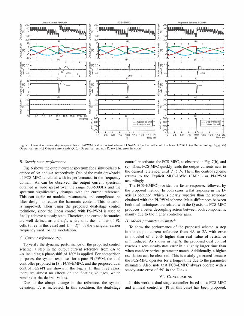
Fig. 7. Current reference step response for a PI+PWM, a dual control scheme FCS+EMPC and a dual control scheme FCS+PI: (a) Output voltage VaN ; (b)Output current; (c) Output current axis Q; (d) Output current axis D; (e) joint error function.
B. Steady-state performance
Fig. 6 shows the output current spectrum for a sinusoidal ref-erence of 6A and 4A respectively. One of the main drawbacksof FCS-MPC is related with its performance in the frequencydomain. As can be observed, the output current spectrumobtained is wide spread over the range 500-5000Hz and thespectrum significatively changes with the current reference.This can excite no modeled resonances, and complicate thefilter design to reduce the harmonic content. This situationis improved, when using the proposed dual-stage controltechnique, since the linear control with PS-PWM is used tofinally achieve a steady state. Therefore, the current harmonicsare well defined around nft, where n is the number of FCcells (three in this case) and ft = T−1
t is the triangular carrierfrequency used for the modulation.
C. Current reference step
To verify the dynamic performance of the proposed controlscheme, a step in the output current reference from 6A to4A including a phase-shift of 180o is applied. For comparisonpurposes, the system responses for a pure PI+PWM, the dualcontroller proposed in [8], FCS+EMPC, and the proposed dualcontrol FCS+PI are shown in the Fig. 7. In this three cases,there are almost no effects on the floating voltages, whichremains at the desired values.
Due to the abrupt change in the reference, the systemdeviation, J , is increased. In this condition, the dual-stage
controller activates the FCS-MPC, as observed in Fig. 7(b), and(c). Thus, FCS-MPC quickly leads the output currents near tothe desired reference, until J < Jl. Then, the control schemereturns to the Explicit MPC+PWM (EMPC) or PI+PWMaccordingly.
The FCS+EMPC provides the faster response, followed bythe proposed method. In both cases, a flat response in the D-axis is obtained, which is clearly superior than the responseobtained with the PI-PWM scheme. Main differences betweenboth dual techniques are related with the Q-axis, as FCS-MPCproduces a better decoupling action between both components,mainly due to the higher controller gain.
D. Model parameter mismatch
To show the performance of the proposed scheme, a stepin the output current reference from 4A to 2A with errorin modeled of a 20% higher than real value of resistanceis introduced. As shown in Fig. 8, the proposed dual controlreaches a zero steady-state error in a slightly larger time thanwhen consider perfect parameter match. Additionally, a higheroscillation can be observed. This is mainly generated becausethe FCS-MPC operates for a longer time due to the parametermismatch. Also, note that FCS+EMPC always operate with asteady-state error of 5% in the D-axis.
VI. CONCLUSIONS
In this work, a dual-stage controller based on a FCS-MPCand a lineal controller (PI in this case) has been proposed.

-200
-100
0
100
200
0
0.5
1
-0.5
-1
Ou
tpu
t cu
rre
nt
axis
D [
A]
Ou
tpu
t cu
rre
nt
axis
Q [
A]
Ou
tpu
t cu
rre
nt
[A]
Ou
tpu
t vo
lta
ge
s[V
]
8
8
4
4
0
0
-4
-4
-8
-8
Time [ms]
Jo
int
err
or
0
200
400
600
800
Upper boundLower bound
(a)
(b)
(d)
c)(
Proposed scheme MPC+PI
Time [ms]
Upper boundLower bound
MPC+LQRJo
int
err
or
0
200
400
600
800
0 30
(e)
5 10 15 20 250 305 10 15 20 25(e)
-200
-100
0
100
200
0
0.5
1
-0.5
-1
Ou
tpu
t cu
rre
nt
axis
D [
A]
Ou
tpu
t cu
rre
nt
axis
Q [
A]
Ou
tpu
t cu
rre
nt
[A]
Ou
tpu
t vo
lta
ge
s[V
]
8
8
4
4
0
0
-4
-4
-8
-8
(a)
(b)
(d)
c)(
6A
0.39A 0.26A
4A
Fig. 8. Current reference step response for FCS+EMPC and FCS+PI with parameter mismatch: (a) Output voltage VaN ; (b) Output current; (c) Output currentaxis Q; (d) Output current axis D; (e) Joint error function.
The proposed structure has been used to control a 4-levelFC converter. The proposed controller combines the excellentdynamic behavior of FCS-MPC with the good steady-state per-formance offers by PWM-based linear controllers, obtaining,thus, a defined spectra and zero average steady-state error, evenwhen system parameter uncertainties are present.
Special considerations has been taken into account to guar-anty a soft transitions between the controllers, obtaining agentle bump-less transition.
ACKNOWLEDGES
The authors acknowledge the support of the ChileanResearch Council (CONICYT) under grant FONDECYT1100697 and the Australian Research Council’s DiscoveryProjects funding scheme (project numbers DP0988601 andDP110103074).
REFERENCES
[1] S. Muller, U. Ammann, and S. Rees, “New time-discrete modulationscheme for matrix converters,” IEEE Transactions on Industrial Elec-tronics, vol. 52, no. 6, pp. 1607–1615, Dec. 2005.
[2] P. Lezana, R. P. Aguilera, and D. E. Quevedo, “Model predictive controlof an asymmetric flying capacitor converter,” IEEE Transactions onIndustrial Electronics, vol. 56, no. 6, pp. 1839–1846, June 2009.
[3] S. Kouro, P. Cortés, R. Vargas, U. Ammann, and J. Rodriguez, “Modelpredictive control& simple and powerful method to control powerconverters,” IEEE Transactions on Industrial Electronics, vol. 56, no. 6,pp. 1826–1838, June 2009.
[4] R. P. Aguilera, P. Lezana, D. E. Quevedo, “Finite-control-set modelpredictive control with improved steady-state performance,” IEEE Trans-actions On Industrial Informatics, vol. 9, no. 2, pp. 658–667, 2013.
[5] P. Cortés, J. Rodríguez, D. E. Quevedo, and C. Silva, “PredictiveCurrent Control Strategy With Imposed Load Current Spectrum,” PowerElectronics, IEEE Transactions on, vol. 23, no. 2, pp. 612–618, 2008.
[6] P. Cortés, S. Kouro, B. La Rocca, R. Vargas, J. Rodriguez, J. I. Leon,S. Vazquez, and L. G. Franquelo, “Guidelines for weighting factorsdesign in model predictive control of power converters and drives,”in Proc. IEEE International Conference on Industrial Technology ICIT2009, 10–13 Feb. 2009, pp. 1–7.
[7] P. Cortés, M. P. Kazmierkowski, R. M. Kennel, D. E. Quevedo, andJ. Rodríguez, “Predictive Control in Power Electronics and Drives,”Industrial Electronics, IEEE Transactions on, vol. 55, no. 12, pp. 4312–4324, Dec. 2008.
[8] R. P. Aguilera, P. Lezana, D.E. Quevedo, “A switched Model PredictiveControl formulation for Flying Capacitor Converters,” in 15th Interna-tional Power Electronics and Motion Control Conference (EPE/PEMC),2012, 3-6 September 2012, Novi Sad, Serbia.
[9] T. A. Meynard, H. Foch, “Multi-level choppers for high voltage applica-tions,” Journal of European Power Electronics and Drives, vol. 2, no. 1,pp. 45–50, March 1992.
[10] K. Corzine and Y. Familiant, “A new cascaded multilevel h-bridge drive,”IEEE Transactions on Power Electronics, vol. 17, no. 1, pp. 125–131,Jan. 2002.
[11] J. Huang and K. A. Corzine, “Extended operation of flying capacitormultilevel inverters,” IEEE Transactions on Power Electronics, vol. 21,no. 1, pp. 140–147, Jan. 2006.
[12] R. H. Wilkinson, T. H. Meynard, and H. du Toit Mouton, “Naturalbalance of multicell converters: The general case,” IEEE Transactionson Power Electronics, vol. 21, no. 6, pp. 1658–1666, Nov. 2006.
[13] B. Reznikov and A. Ruderman, “Five-level single-leg flying capacitorconverter voltage balance dynamics analysis,” in Proc. 35th AnnualConference of the IEEE Industrial Electronics Society - IECON 2009,Portugal, Porto, 3–5 Nov. 2009, pp. 1–6.
[14] T. J. Vyncke, S. Thielemans, and J. A. Melkebeek, “Finite-Set Model-Based Predictive Control for Flying-Capacitor Converters: Cost FunctionDesign and Efficient FPGA Implementation,” Industrial Informatics,IEEE Transactions on, vol. 9, no. 2, pp. 1113–1121, 2013.
[15] B. McGrath, T. Meynard, G. Gateu, D. Holmes, “Optimal Modulationof Flying Capacitor and Stacked Multicell Converters Using a StateMachine Decoder,” IEEE Transactions on Power Electronics, vol. 22,no. 2, pp. 508–516, 2007.

[16] G. Goodwing, S. Graebe, M. Salgado, “Control System Design”.ISBN: 0139586539: Prentice Hall, 2000.
Related Documents