ZHEJIANG DAHUA VISION TECHNOLOGY CO., LTD. V1.0.5 DSS Pro User’s Manual

Welcome message from author
This document is posted to help you gain knowledge. Please leave a comment to let me know what you think about it! Share it to your friends and learn new things together.
Transcript

ZHEJIANG DAHUA VISION TECHNOLOGY CO., LTD.
ZHEJIANG DAHUA VISION TECHNOLOGY CO., LTD.
V1.0.5
V1.0.0
DSS Pro
User’s Manual

User’s Manual
II
Foreword
General
This user’s manual (hereinafter referred to as "the manual") introduces the functions and
operations of the DSS general surveillance management center (hereinafter referred to as "the
system" or "the platform") and client operations.
Safety Instructions
The following categorized signal words with defined meaning might appear in the manual.
Signal Words Meaning
DANGER
Indicates a high potential hazard which, if not avoided, will result
in death or serious injury.
WARNING
Indicates a medium or low potential hazard which, if not
avoided, could result in slight or moderate injury.
CAUTION
Indicates a potential risk which, if not avoided, could result in
property damage, data loss, lower performance, or
unpredictable result.
TIPS Provides methods to help you solve a problem or save you time.
NOTE Provides additional information as the emphasis and
supplement to the text.

User’s Manual
III
Revision History
Document
Version Software Version Revision Content Release Time
V1.0.5 V7.002.0000005.0
Optimized visitor
management, live view,
playback, face
recognition, target
detection, access
control, business
intelligence, storage
configuration, thermal,
event management, and
entrance control
functions.
Added M+N deployment
Optimized writing style.
April 2020
V1.0.4 V7.002.0000003.1
Modified license
strategy and radar-PTZ
linkage
Added custom event
and people counting
rule configuration.
December 2019
V1.0.3 V7.002.0000003
Added visitor
management, alarm
controller, business
intelligence, radar-PTZ
smart track, electronic
focus, and AI search
and intelligent analysis
configuration.
Optimized instructions
including authorization,
device configuration,
face recognition,
personnel management
and access control.
October 2019

User’s Manual
IV
Document
Version Software Version Revision Content Release Time
V1.0.2 V7.002.0000002
Added new functions
such as entrance,
attendance and video
intercom.
Modified access control
and deleted commercial
functions.
March 2019
V1.0.1 V7.002.0000001
Added new functions
such as person
management, access
control management,
thermal, target
detection, device
configuration.
Modified contents such
as edit device, flow
analysis, plate
recognition.
December 2018
V1.0.0 V7.002.0000000 First release September 2018
Privacy Protection Notice
As the device user or data controller, you might collect personal data of others such as face,
fingerprints, car plate number, email address, phone number, GPS and so on. You need to be in
compliance with the local privacy protection laws and regulations to protect the legitimate rights
and interests of other people by implementing measures include but not limited to: providing
clear and visible identification to inform data subject the existence of surveillance area and
providing related contact.
About the Manual
The Manual is for reference only. If there is inconsistency between the manual and the
actual product, the actual product shall prevail.
We are not liable for any loss caused by the operations that do not comply with the manual.
The manual would be updated according to the latest laws and regulations of related
regions. For detailed information, see the paper manual, CD-ROM, QR code or our official
website. If there is inconsistency between paper manual and the electronic version, the
electronic version shall prevail.
All the designs and software are subject to change without prior written notice. The product

User’s Manual
V
updates might cause some differences between the actual product and the manual. Please
contact the customer service for the latest program and supplementary documentation.
There still might be deviation in technical data, functions and operations description, or
errors in print. If there is any doubt or dispute, please see our final explanation.
Upgrade the reader software or try other mainstream reader software if the manual (in PDF
format) cannot be opened.
All trademarks, registered trademarks and the company names in the manual are the
properties of their respective owners.
Please visit our website, contact the supplier or customer service if there is any problem
occurred when using the device.
If there is any uncertainty or controversy, please see our final explanation.

User’s Manual
VI
Table of Contents
Foreword ................................................................................................................................................... II
1 Overview ................................................................................................................................................. 1
Introduction ................................................................................................................................... 1 1.1
Highlights ...................................................................................................................................... 1 1.2
2 Installation and Deployment ................................................................................................................ 2
Server Requirements .................................................................................................................... 2 2.1
Installing Master Server ................................................................................................................ 2 2.2
Installing Slave Server .................................................................................................................. 6 2.3
Managing Platform Services ....................................................................................................... 10 2.4
Configuring LAN or WAN ............................................................................................................. 11 2.5
2.5.1 Configuring Router ............................................................................................................. 11
2.5.2 Configuring DSS Platform ................................................................................................. 11
Uninstalling the platform ............................................................................................................. 13 2.6
3 Basic Configurations .......................................................................................................................... 14
Logging in to Web Manager ........................................................................................................ 14 3.1
Activating the Platform ................................................................................................................ 15 3.2
3.2.1 License Capacity .............................................................................................................. 15
3.2.2 Applying for a License ...................................................................................................... 16
3.2.3 Activating or Updating License ......................................................................................... 16
Adding Organization .................................................................................................................... 20 3.3
Managing Device ........................................................................................................................ 22 3.4
3.4.1 Searching for Online Devices ........................................................................................... 22
3.4.2 Initializing Devices ............................................................................................................ 23
3.4.3 Modifying Device IP Address ............................................................................................ 25
3.4.4 Adding Devices ................................................................................................................. 26
3.4.5 Editing Devices ................................................................................................................. 32
3.4.6 Binding Resources ............................................................................................................ 36
Adding Role and User ................................................................................................................. 37 3.5
3.5.1 Adding User Role .............................................................................................................. 37
3.5.2 Adding User ...................................................................................................................... 38
3.5.3 (Optional) Setting Domain User........................................................................................ 40
Configuring Record Plan ............................................................................................................. 41 3.6
3.6.1 Configuring Storage Disk .................................................................................................. 41
3.6.2 Configuring Disk Group Quota ......................................................................................... 44
3.6.3 Adding Recording Plan ..................................................................................................... 46
3.6.4 Configuring Storage Backup............................................................................................. 48
3.6.5 Adding Time Template ...................................................................................................... 49
Configuring Map .......................................................................................................................... 51 3.7
3.7.1 Adding Map ....................................................................................................................... 52
3.7.2 Marking Devices ............................................................................................................... 57
4 Business Functions ............................................................................................................................ 59
Preparations ................................................................................................................................ 59 4.1

User’s Manual
VII
4.1.1 Installing Client ................................................................................................................. 59
4.1.2 Logging in to Client ........................................................................................................... 62
4.1.3 Homepage of Control Client ............................................................................................. 64
4.1.4 Local Configuration ........................................................................................................... 65
Live View ..................................................................................................................................... 75 4.2
4.2.1 Typical Topology ............................................................................................................... 75
4.2.2 Preparations ..................................................................................................................... 75
4.2.3 Viewing Live Video ........................................................................................................... 76
4.2.4 Electronic Focus ............................................................................................................... 84
4.2.5 Tour ................................................................................................................................... 86
4.2.6 View .................................................................................................................................. 86
4.2.7 Favorites ........................................................................................................................... 87
4.2.8 Region of Interest (RoI) .................................................................................................... 90
4.2.9 PTZ ................................................................................................................................... 91
Configuring Device Parameters .................................................................................................. 97 4.3
4.3.1 Configuring Camera Properties ........................................................................................ 97
4.3.2 Video ............................................................................................................................... 108
4.3.3 Audio ................................................................................................................................113
Event and Alarm .........................................................................................................................114 4.4
4.4.1 Configuring Events ..........................................................................................................115
4.4.2 Viewing Alarms ............................................................................................................... 127
Intelligent Analysis .................................................................................................................... 130 4.5
4.5.1 Typical Topology ............................................................................................................. 130
4.5.2 Configuring Intelligent Analysis....................................................................................... 131
Fisheye-PTZ Smart Track ......................................................................................................... 154 4.6
4.6.1 Typical Topology ............................................................................................................. 154
4.6.2 Business Flow ................................................................................................................. 155
4.6.3 Configuring Fisheye-PTZ Smart Track ........................................................................... 155
4.6.4 Applying Fisheye-PTZ Smark Track ............................................................................... 158
Bullet-PTZ Smart Track ............................................................................................................. 159 4.7
4.7.1 Typical Topology ............................................................................................................. 160
4.7.2 Business Flow ................................................................................................................. 160
4.7.3 Configuring Bullet-PTZ Smart Track ............................................................................... 161
4.7.4 Applying Bullet-PTZ Smart Track ................................................................................... 163
Radar-PTZ Smart Track ............................................................................................................ 170 4.8
4.8.1 Typical Topology ............................................................................................................. 170
4.8.2 Business Flow ................................................................................................................. 171
4.8.3 Configuring Radar-PTZ Smart Track .............................................................................. 171
4.8.4 Radar-PTZ Smart Track Monitoring ............................................................................... 180
Record ....................................................................................................................................... 183 4.9
4.9.1 Preparations ................................................................................................................... 183
4.9.2 Playback ......................................................................................................................... 183
4.9.3 POS Search .................................................................................................................... 191
4.9.4 Searching by Thumbnail ................................................................................................. 192
Video Wall ............................................................................................................................... 195 4.10
4.10.1 Typical Topology ........................................................................................................... 196

User’s Manual
VIII
4.10.2 Business Flow ............................................................................................................... 197
4.10.3 Configuring Video Wall ................................................................................................. 197
4.10.4 Video Wall Applications ................................................................................................ 207
Traffic ....................................................................................................................................... 210 4.11
4.11.1 Typical Topology .............................................................................................................211
4.11.2 Business Flow ................................................................................................................211
4.11.3 Configuring Traffic Monitoring ....................................................................................... 212
4.11.4 Traffic Management Applications .................................................................................. 216
ANPR....................................................................................................................................... 221 4.12
4.12.1 Typical Topology ........................................................................................................... 222
4.12.2 Business Flow ............................................................................................................... 222
4.12.3 Configuring ANPR......................................................................................................... 223
4.12.4 ANPR Applications ........................................................................................................ 226
Entrance .................................................................................................................................. 234 4.13
4.13.1 Typical Topology ........................................................................................................... 234
4.13.2 Business Flow ............................................................................................................... 235
4.13.3 Configuring Entrance Settings ...................................................................................... 236
4.13.4 Entrance Applications ................................................................................................... 247
POS ......................................................................................................................................... 256 4.14
4.14.1 Typical Topology ........................................................................................................... 256
4.14.2 Business Flow ............................................................................................................... 257
4.14.3 Configuring POS Monitoring ......................................................................................... 257
4.14.4 POS Applications .......................................................................................................... 259
Flow Analysis .......................................................................................................................... 263 4.15
4.15.1 Typical Topology ........................................................................................................... 264
4.15.2 Business Flow ............................................................................................................... 265
4.15.3 Configuring Flow Analysis ............................................................................................ 265
4.15.4 Flow Analysis Applications ............................................................................................ 279
Human Face Recognition ....................................................................................................... 286 4.16
4.16.1 Typical Topology ........................................................................................................... 286
4.16.2 Business Flow ............................................................................................................... 288
4.16.3 Configuring Face Recognition ...................................................................................... 288
4.16.4 Face Recognition Applications ..................................................................................... 296
Target Detection ...................................................................................................................... 306 4.17
4.17.1 Typical Topology ........................................................................................................... 307
4.17.2 Business Flow ............................................................................................................... 307
4.17.3 Target Detection Applications ....................................................................................... 308
Thermal ................................................................................................................................... 314 4.18
4.18.1 Typical Topology ........................................................................................................... 315
4.18.2 Business Flow ............................................................................................................... 315
4.18.3 Thermal Applications .................................................................................................... 316
Personnel Management .......................................................................................................... 329 4.19
4.19.1 Configuring Personnel Information ............................................................................... 330
4.19.2 Configuring Door Groups .............................................................................................. 351
4.19.3 Configuring Admin Passwords ..................................................................................... 353
4.19.4 Configuring Time Templates ......................................................................................... 354

User’s Manual
IX
4.19.5 Configuring Holiday Schedules .................................................................................... 356
Access Control ........................................................................................................................ 358 4.20
4.20.1 Typical Topology ........................................................................................................... 359
4.20.2 Business Flow ............................................................................................................... 360
4.20.3 Configuring Access Control .......................................................................................... 360
4.20.4 Access Control Applications ......................................................................................... 379
Video Intercom ........................................................................................................................ 389 4.21
4.21.1 Typical Topology ........................................................................................................... 389
4.21.2 Business Flow ............................................................................................................... 389
4.21.3 Configuring Video Intercom .......................................................................................... 390
4.21.4 Video Intercom Applications ......................................................................................... 400
Attendance Management ........................................................................................................ 409 4.22
4.22.1 Typical Topology ........................................................................................................... 409
4.22.2 Business Flow ............................................................................................................... 410
4.22.3 Configuring Attendance ................................................................................................ 410
4.22.4 Viewing Attendance Report .......................................................................................... 426
Visitor Management ................................................................................................................ 429 4.23
4.23.1 Preparations ................................................................................................................. 430
4.23.2 Business Flow ............................................................................................................... 430
4.23.3 Configuring Visit Settings ............................................................................................. 430
4.23.4 Visitor Appointment ....................................................................................................... 432
4.23.5 Checking In ................................................................................................................... 434
4.23.6 Checking Out ................................................................................................................ 437
4.23.7 Searching for Visit Records .......................................................................................... 438
Business Intelligence .............................................................................................................. 438 4.24
4.24.1 Typical Topology ........................................................................................................... 439
4.24.2 Business Flow ............................................................................................................... 440
4.24.3 Configuring Business Intelligence ................................................................................ 440
4.24.4 Business Intelligence Applications ............................................................................... 445
Alarm Controller ...................................................................................................................... 451 4.25
4.25.1 Preparations ................................................................................................................. 451
4.25.2 Alarm Controller Interface ............................................................................................. 453
4.25.3 Updating Alarm Controller Status ................................................................................. 455
4.25.4 Arming/Disarming ......................................................................................................... 456
4.25.5 Bypassing/Isolating/Normal .......................................................................................... 459
Configuring N+M ..................................................................................................................... 462 4.26
Cascade .................................................................................................................................. 465 4.27
4.27.1 Typical Topology ........................................................................................................... 466
4.27.2 Configuring Cascade .................................................................................................... 466
System Configuration .............................................................................................................. 468 4.28
4.28.1 HTTPs Certificate ......................................................................................................... 468
4.28.2 Setting Mail Server ....................................................................................................... 468
4.28.3 Setting Device Login Mode........................................................................................... 469
Server Management ............................................................................................................... 469 4.29
4.29.1 Server Management ..................................................................................................... 470
4.29.2 Resource Config ........................................................................................................... 470

User’s Manual
X
Password Maintenance ........................................................................................................... 472 4.30
4.30.1 Modifying Password ..................................................................................................... 472
4.30.2 Resetting Password ...................................................................................................... 472
5 Maintenance ....................................................................................................................................... 475
Setting System Data Retention Period ..................................................................................... 475 5.1
Updating App Certificate ........................................................................................................... 475 5.2
Remote Log ............................................................................................................................... 476 5.3
Time Synchronization ................................................................................................................ 476 5.4
5.4.1 Automatic Time Synchronization .................................................................................... 476
5.4.2 Manual Time Synchronization ........................................................................................ 477
Backup and Restore ................................................................................................................. 478 5.5
5.5.1 System Backup ............................................................................................................... 478
5.5.2 System Restore .............................................................................................................. 479
Log ............................................................................................................................................ 482 5.6
System Maintenance ................................................................................................................ 482 5.7
5.7.1 Overview ......................................................................................................................... 482
5.7.2 Running Status ............................................................................................................... 483
5.7.3 Status Information ........................................................................................................... 484
5.7.4 Event Information ............................................................................................................ 485
5.7.5 Source Information ......................................................................................................... 486
Service Module Introduction .......................................................................................... 488 Appendix 1
Cybersecurity Recommendations ................................................................................. 490 Appendix 2

User’s Manual
1
1 Overview
Introduction 1.1
DSS Pro is a flexible, easily-extendable, highly-reliable and professional video surveillance
software. It meets the requirements of large and medium-sized projects through distributed
deployment and cascade. In addition to the basic video surveillance business, it also delivers a
number of AI functions such as target detection, face recognition, license plate recognition,
people counting, and more. It also provides the add-on modules of transportation and business
analysis, and access control. These functions enable the platform to be widely used in chain
supermarket, casino, safe city, road monitoring, medium and large-sized campus surveillance
and more scenarios.
Highlights 1.2
Easily extendable
Supports distributed deployment for optimal system performance.
Supports cascading for large system management.
Provides Add-ons.
More professional
Supports system operation and maintenance for easily acquiring information of
service, system, device, time and more.
Supports radar-PTZ smart track, target detection, face recognition, plate recognition,
people counting and other AI functions, access control, retail and transportation
functions, making DSS Pro more powerful.
Highly reliable
Supports hot standby and N+M deployment to guarantee system stability.
Supports auto and manual backup of system data to reduce loss caused by system
crash.
More open
Supports ONVIF protocol and active registration.
Provides open SDK for third party integration.

User’s Manual
2
2 Installation and Deployment
DSS platform supports both single server deployment and master/slave distributed
deployment.
Server Requirements 2.1
Table 2-1 Hardware requirement
Parameter Hardware Requirement Operating System
Recommended
configuration
CPU: Intel Xeon Silver 4114@
2.2GHz 10 Core Processor
RAM: 16 GB
Network card: 4 Ethernet port @
1000 Mbps
Hard drive type: HDD 1TB
DSS installation directory
space: Over 500 GB
Win10-64bit
Windows server 2008
Windows server 2012
Windows server 2016
Windows server 2019
Minimum
configuration
CPU: E3-1220 [email protected] 4
Core Processor
RAM: 8 GB
Network card: 2 Ethernet port @
1000 Mbps
Hard drive type: HDD 1TB
DSS installation directory
space: Over 500 GB
Win10-64bit
Installing Master Server 2.2
Double-click . Step 1
Program name includes version number and program data, please confirm it before
installation.

User’s Manual
3
Agreement interface Figure 2-1
Click agreement, read the agreement, and then select the check box of I have read Step 2
and agree to the DSS agreement. Click Next.
Select server type Figure 2-2
Select a server type, and then click Next. Step 3
Select Master if the current server is the only server of your platform or the master
server in the distributed deployment of the system.
Select Slave if the current server is a slave server.

User’s Manual
4
Select installation path Figure 2-3
Select the installation path. You can click Browse to customize the installation Step 4
directory.
After selecting installation directory, the system displays the required space and current
free space.
It is not recommended that you install the platform in to Disk C because features
such as face recognition require higher disk performance.
If the Install button is gray, check if the installation directory is correct, or if free
space is larger than the required space.
Click Install. Step 5
The installation process takes about 3 to 5 minutes. The Run interface is displayed
after the installation is completed.

User’s Manual
5
End of installation Figure 2-4
Click Run. Step 6
Network config Figure 2-5
Select a network card, and then click OK. Step 7
The security setting interface is displayed.

User’s Manual
6
Enable TLS1.0 Figure 2-6
Enable or disable TLS1.0 protocol as needed. Step 8
Click OK. Step 9
Installing Slave Server 2.3
Double-click installation program . Step 1
The program name includes version number and program data, please confirm it
before installation.

User’s Manual
7
Agreement interface Figure 2-7
Click the agreement, read and accept agreement protocol, select I have read and Step 2
agree the DSS agreement, click Next.
Select server type Figure 2-8
Select installation mode as Slave, click Next. Step 3

User’s Manual
8
Select installation path Figure 2-9
Select installation path, supports default installation path, click Browse to customize Step 4
installation directory.
After selecting directory, the system displays space needed for installation and
available space for selected path.
It is not recommended that you install the platform in to Disk C because features
such as face recognition require higher disk performance.
If the Install button is gray, check if the installation directory is correct, or if free
space is larger than the required space.
Click Install. Step 5
The installation process needs about 3 to 5 minutes.

User’s Manual
9
Installation completed Figure 2-10
Click Run. Step 6
Select network card Figure 2-11
Select the network card you need and click OK. Step 7
Configure master server information on the slave server. Step 8
1) Double-click on the slave server.
2) Click at the upper-right corner of the interface.
3) Set Center IP, Local IP and each port number, and then click OK.
Enter master server IP address in the Center IP box, and master server port
numbers in the port number boxes.
Enter slave server IP address and WAN IP address in the Local IP box and
Mapping IP box.
If the IP addresses and ports are valid, the slave server services will restart.

User’s Manual
10
Managing Platform Services 2.4
View service status, start or stop services, and modify service ports.
Log in to the server, and then double-click .
Service management interface Figure 2-12
Table 2-2 Parameters
No. Function Description
1 Service
Management
Service management, it supports following three types of operation:
Click to restart all services.
Click to stop all services.
Click to refresh services.
2 User's
manual User's manual.
3 Language Switch language.
4 Security
Setting
Enable or disable the TSL 1.0 protocol. TSL 1.0 protocol is a
non-security protocol and is recommended to be closed. If TLS 1.0
protocol is disabled, ensure that the browser has proper access to the
platform. To enable TLS1.1 and TLS 1.2, open your browser, select
> Internet Options > Advanced.

User’s Manual
11
No. Function Description
5 Setting Set server IP as the platform CMS IP. If the network has to go across
LAN and WAN, you need to enter WAN IP in the Mapping IP box.
6 About Software version information.
7 Minimize Minimize the interface.
8 Close Close.
9 Service
Status
: Service exception
: Service is running normally
10 Services
Display each service and service status. Click to modify service
port number, and then services will restart automatically after
modification.
11
Open
Administrator
Client
Go to the Web Manager which is used by system administrators.
Configuring LAN or WAN 2.5
2.5.1 Configuring Router
If the platform is in a local network, to visit it from the public network, you need to do port
mapping. For the list of the ports to be mapped, see "Appendix 1 Service Module Introduction".
2.5.2 Configuring DSS Platform
Log in to DSS server, and then double-click . Step 1

User’s Manual
12
Service status Figure 2-13
Click the on the upper-right corner. Step 2
Setting Figure 2-14
Enter WAN address in the Mapping IP box, and then click OK. Step 3
Click OK and then services restart. Step 4

User’s Manual
13
Uninstalling the platform 2.6
On the server, go to the service directory "..\DSS Pro\Server\Uninstall", and then Step 1
double-click "uninst.exe".
Confirm uninstallation Figure 2-15
Click Yes. Step 2
Uninstallation completed Figure 2-16
Click Finish.Step 3

User’s Manual
14
3 Basic Configurations
Configure basic settings of the system functions before you can use them, such as system
activation, organization and device management, user creation, storage and recording planning,
and event rules configuration. The basic configurations are made on Web Manager, the web
client of DSS Pro. To log in to Web Manager, you are recommended to use Google Chrome 70
and later, and Firefox 56 and later, and IE 11.
Logging in to Web Manager 3.1
Log in to the Web Manager via browser to perform remote configuration of the system.
Enter platform IP address in the browser, and then press Enter. Step 1
Log in to the Web Manager Figure 3-1
Enter username and password, and then click Login. Step 2
The default username is system.
The system will pop out the interface of modifying password if it is the first time to
log in system. It can continue to log in system after the password is modified in
time.
Please add the platform IP address into the trusted sites of browser if it is your
first time to log in DSS Web Manager.

User’s Manual
15
Homepage Figure 3-2
Place the mouse pointer on the username of upper-right corner, and then you can modify
password or log out current user.
The shortcut access of general modules is displayed on the top of interface, click on
the homepage to present all the modules and open new modules.
Overview: It displays the online/offline status of device, user and service, and the usage
proportion of hard drive.
License: Activate or update license, and check license details.
Help: Check user's manual and version information.
Activating the Platform 3.2
Activate the platform with a trial or paid license the first time you log in to it. Otherwise you
cannot use it.
This section introduces license capacity, how to apply for a license, how to use license to
activate the platform, and how to renew your license.
3.2.1 License Capacity
A trial license provides limited capacity and expires in 90 days.
To acquire full capacity and permanent use, you shall buy a formal license.
After activating the first paid license, if you want to increase your license capacity, you can
buy more license codes. For example, if you have 500 channels currently, you can buy
another 500 channels. After activating the new 500 channels, you will have 1,000 channels
in total.
The activated official version cannot be downgraded to the trail version.

User’s Manual
16
3.2.2 Applying for a License
To get a formal license, contact the sales personnel.
To apply for a trail license, see the following instructions.
Go to https://www.dahuasecurity.com/products/productDetail/35647. Step 1
Click Apply for DEMO, and then follow the onscreen guide to complete and submit the Step 2
application.
In 2 or 3 days after the application, you will receive a system email that contains your
trial license.
3.2.3 Activating or Updating License
Activate the platform with a trial or formal license for first-time login. Otherwise you cannot use
the platform.
During use of the platform, you can also update your trial or formal license with a new one, so
as to achieve greater capacity or longer use.
To activate or update your license, see the following procedures.
The license activation and update procedures are the same. This section takes license
activation as an example. The actual interface shall prevail.
On the Home interface of the Web Manager, click Activate License. Step 1
Update license Figure 3-3

User’s Manual
17
Activation method selection Figure 3-4
Select an activation method. Step 2
There are two ways to activate the license.
Online activation
Select Online Activate if the platform server is connected to the Internet.
Offline activation
Select Offline Activate if the platform server is disconnected from the Internet.
Online activation
1) On the activation method interface, select Online Activate.

User’s Manual
18
Online activate Figure 3-5
2) Enter the new license key, and then click OK.
After the license is activated successfully, you can click Details of License to view
the details of your license capacity.
Offline activate
1) On the activation method interface, select Offline Activate.
Offline activate Figure 3-6

User’s Manual
19
2) Enter the license code in the License Key box.
3) Click Export to export the license request file.
4) Move the request file to a computer that is connected to the Internet. On that
computer, open the system email that contains your license, and then click the web
page address to go to the license management page.
License management web page Figure 3-7
5) Click Activate License.

User’s Manual
20
Upload license request file Figure 3-8
6) Click Upload, select the license request file, and then when you are prompted
uploaded successfully, click Activate.
The success interface is displayed, where a download prompt is displayed asking
you to save the license activation file.
7) On the success interface, click Save to save the file, and then move the file to back
to the computer where you exported the license request file.
8) On the Offline Activate interface, click Import, and then follow the onscreen
instructions to import the license activation file.
After you are prompted that the platform license is activated, you can click Details
of License to view license capability details.
Adding Organization 3.3
Classify devices by logical organization for the ease of management.
Log in to the Web Manager. Click , and then select Organization on the New Tab Step 1
interface.

User’s Manual
21
Device organization Figure 3-9
Select the root node of the device tree on the left, and then click Add to add new Step 2
organizations under the root node.
Add an organization Figure 3-10
Enter organization name, and then press Enter. Step 3

User’s Manual
22
Operations
Move device: Select the device under the root organization, click , select New
Organization 1, and then click OK.
Edit: Click the next to the organization and modify the organization name.
Delete: Select an organization, and then click .
Managing Device 3.4
Add devices before you can use them for video monitoring. This section introduces how to add,
initialize, and edit devices and how to modify device IP address.
3.4.1 Searching for Online Devices
Search for devices on the same LAN with the platform before you can add them to the platform.
Log in to the Web Manager. Click , and then select Device. Step 1
The platform searches for and displays devices on the same LAN with the platform
server during first-time use.
The platform searches for and displays devices according to the network segment
as defined last time if it is not the first-time use.
Click Network Segment Config. Step 2
Set network segment Figure 3-11
Enter the start IP and end IP, and then click Search. Step 3

User’s Manual
23
Search results Figure 3-12
3.4.2 Initializing Devices
You need to initialize the uninitialized devices before you can add them to the platform.
Log in to the Web Manager. Click , and then select Device. Step 1
Search for devices. See "3.4.1 Searching for Online Devices". Step 2
Search results Figure 3-13
Select an uninitialized device, and then click Initialize. Step 3
You can select multiple devices to initialize them in batches. Make sure that the
selected devices have the same username, password and email information.
Click or next to Init Status to quickly sort out the status column, and then
you can see all the uninitialized devices.

User’s Manual
24
Set password Figure 3-14
Enter the password, and then click Password Secure. Step 4
Password security Figure 3-15
Enter the email address, and then click Change IP. Step 5
The email is used to receive security code for resetting password.

User’s Manual
25
Change IP Figure 3-16
Enter the IP address, and then click OK. Step 6
3.4.3 Modifying Device IP Address
You can modify IP addresses of the devices that have not been added to the platform yet.
Log in to the Web Manager. Click , and then select Device. Step 1
Search for devices. See "3.4.1 Searching for Online Devices". Step 2
Search results Figure 3-17
Select a device, and then click Change IP. Step 3
For devices that have the same username and password, you can select and modify
their IP addresses in batches.
Modify the IP address, and then click OK. Step 4

User’s Manual
26
Verification Figure 3-18
Enter the username and password for logging in to the device, and then click Change Step 5
IP.
Change IP Figure 3-19
Enter the IP address, and then click OK. Step 6
Click OK. Step 7
3.4.4 Adding Devices
You can add different types of devices, such as encoder, decoder, ANPR device, access control,
LED, video intercom and emergency assistance device. In this chapter, take adding encoder as
an example. For other devices, the actual configuration interface shall prevail.

User’s Manual
27
3.4.4.1 Adding Devices One by One
Click and select Device on the New Tab interface. Step 1
Device Figure 3-20
Click Add. Step 2

User’s Manual
28
Add a device (1) Figure 3-21
Set parameters. Step 3
The parameters vary with the selected protocols. The actual interface shall prevail.
In the Add Type drop-down list,
When Auto Register is selected, enter device registration ID. The auto register
method is only for adding encoders and emergency alarm devices. The ID of auto
register has to be in accordance with the registered ID configured at encoder. The
port number must be the same on the platform and on the device. The auto
register port is 9500 on the platform by default. To modify, open the system
configuration tool to modify the DSS_ARS port number.
When Domain Name is selected, the options are from the configured domain
during deployment.
Click Add. Step 4

User’s Manual
29
Add a device (2) Figure 3-22
Set parameters. Step 5
Click OK. Step 6
Click Continue to add more devices.
3.4.4.2 Adding Devices through Searching
Devices on the same LAN with the platform server can be added using the automatic search
function.
Click and select Device on the New Tab interface. Step 1
Search for online devices. Step 2
The search results are displayed.
Select the device which needs to be added, and click Connect. Step 3
You can select multiple devices to add them in batches if they have the same
username and password.

User’s Manual
30
Batch add Figure 3-23
Set parameters, and then click OK. Step 4
The device is added into corresponding organization.
3.4.4.3 Importing Video Intercom Device
Fill in intercom device template, and then you can add intercom devices in batches.
Click and select Device on the interface of New Tab. Step 1
Click Import. Step 2
User’s Manual
31
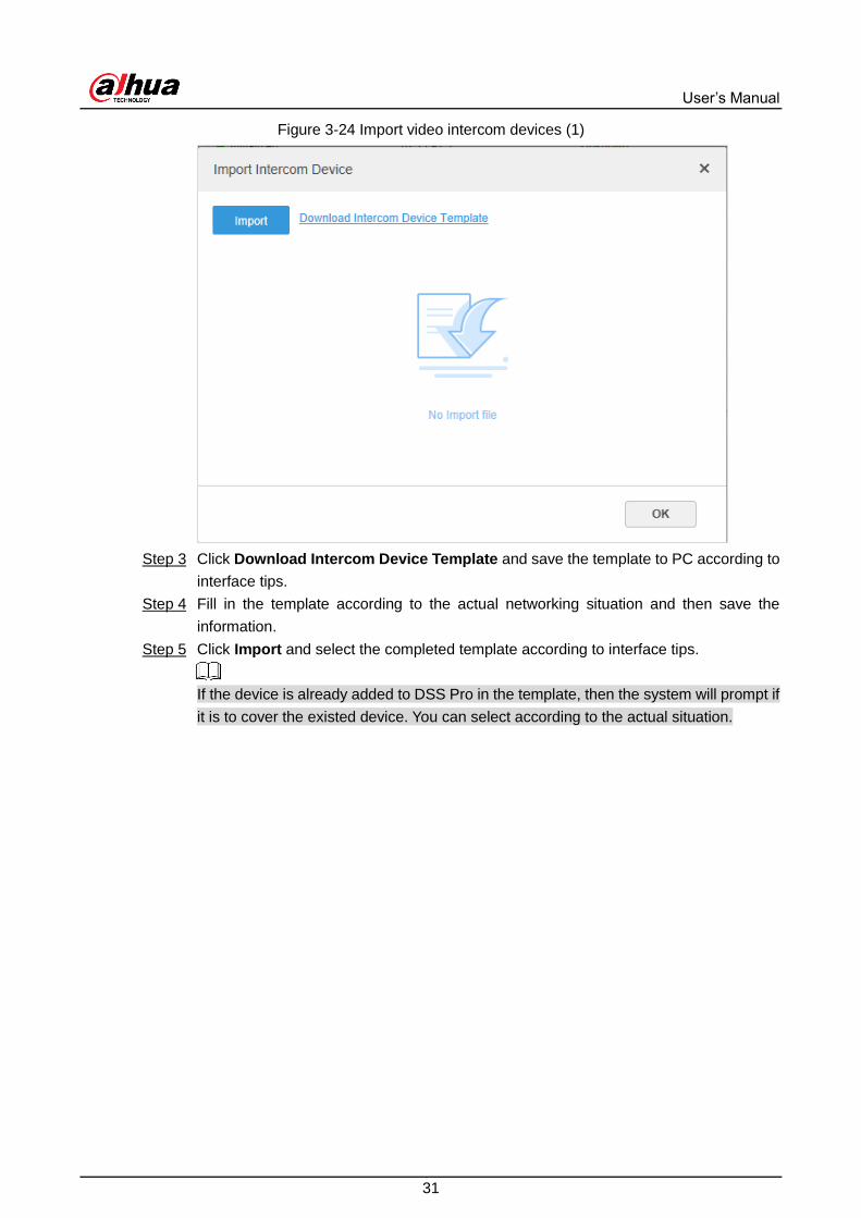
Import video intercom devices (1) Figure 3-24
Click Download Intercom Device Template and save the template to PC according to Step 3
interface tips.
Fill in the template according to the actual networking situation and then save the Step 4
information.
Click Import and select the completed template according to interface tips. Step 5
If the device is already added to DSS Pro in the template, then the system will prompt if
it is to cover the existed device. You can select according to the actual situation.

User’s Manual
32
Import video intercom devices (2) Figure 3-25
Click and close the prompt box. Step 6
Click OK. Step 7
3.4.5 Editing Devices
Modify device information and organization.
3.4.5.1 Modifying Device Information
Click and select Device on the New Tab interface. Step 1
Click the corresponding of device list. Step 2
Click Get Info and the system will synchronize device information.

User’s Manual
33
Basic information Figure 3-26
Modify device basic information on the Basic Info interface. Step 3
Click Video Channel, and then set the device channel name, channel features, Step 4
camera type, No., keyboard code and face function.
Different types of devices have different features; the actual interface shall prevail.
Device features include intelligent alarm, fisheye, face detection, face recognition and
more. Select features according to the capability of the camera.
Set video channel features Figure 3-27

User’s Manual
34
Click the Alarm Input Channel tab, and then configure channel name and alarm type Step 5
of alarm input.
Skip the step unless when the added devices support alarm input.
Alarm type includes external alarm, IR detect, zone disarm, PIR, gas sensor,
smoke sensor, glass sensor, emergency button, stolen alarm, perimeter and
preventer move.
Alarm type supports custom. Select Customize Alarm Type in the Alarm Type
drop-down list. Click Add to add new alarm type. It supports max 30 custom
newly-added alarm types.
Custom alarm supports modification and deletion.
If custom alarm type is used by alarm plan, then it is not allowed to deleted but
modified.
When the name of the custom alarm type is modified, the history data remains
the original name, while the new data adopts the modified name.
The alarm input channel of alarm host is Alarm Host Alarm by default; the types
of other alarm input channel are External Alarm by default.
Alarm type Figure 3-28
Click the Alarm Output Channel tab and then modify the name of alarm output Step 6
channel.

User’s Manual
35
Modify alarm output name Figure 3-29
Click OK to finish modification. Step 7
3.4.5.2 Modifying Device Organization
You can move a device from an organization node to another one.
Click . On the New Tab interface, select Organization. Step 1
Select a device to be moved, and then click Move To. Step 2
Move device Figure 3-30
Select the target organization node, and then click OK. Step 3

User’s Manual
36
3.4.6 Binding Resources
The platform supports binding resources for linked actions. You can bind a video channel with
an alarm input channel, ANPR channel, POS channel, access control channel or another video
channel, so that you can view the associated video for alarm, face and other businesses.
Adding Resource Bind
Log in to the Web Manager. Click , and then select Device. Step 1
Click Resource Bind. Step 2
Bind resource Figure 3-31
Click Add. Step 3

User’s Manual
37
Add resource to bind Figure 3-32
Select source channel and video channel respectively, and then click OK. Step 4
Adding Role and User 3.5
Users of different roles have different permissions of device access and operation. When
creating a user, assign a role to it to give the corresponding permissions.
3.5.1 Adding User Role
A role is a set of permission. Classify users of the platform into different roles so that they can
have different permissions for operating the devices, functions and other system resources.
Log in to the Web Manager. Click , and then select User. Step 1
Click the Role tab. Step 2
Click Add, set role information, and then select device and control permissions and Step 3
assign the rule to users.

User’s Manual
38
Select a role from the Copy from drop-down list to copy the settings to the
selected rules.
If no device and control permissions are selected for the user, this user will not
have the corresponding permissions.
Add a role Figure 3-33
Click OK. Step 4
3.5.2 Adding User
Create a user account for logging in to the platform.
Log in to the Web Manager. Click , and then select User. Step 1
Click User tab. Step 2

User’s Manual
39
Add a user (1) Figure 3-34
Click Add. Step 3
Add a user (2) Figure 3-35
Configure user information, select role below, and it will display device permission and Step 4
operation permission of corresponding role on the right.

User’s Manual
40
The user has no Device Permission or Operation Permission if it fails to select
Role.
You can select several roles at the same time.
Click OK to add the user. Step 5
Operations
Click to freeze user. The frozen user cannot log in to the Control Client, Web Manager
and App.
Click to modify user information except username.
Click to delete user.
3.5.3 (Optional) Setting Domain User
This setting is optional. You can import domain users from the domain system of your current
organization to create platform users.
Configuring Domain Information Step 1
1) Log in to the Web Manager. Click , and then select System on the New Tab
interface.
2) Click Active Directory and configure domain information.
3) Select the Enable check box, and then set domain information.
After setting domain information, click Get DN and it will acquire basic DN
information automatically.
After getting DN information, click Test to test if domain information is
available.
Set active directory Figure 3-36
4) Click Save.
Import domain users. Step 2
1) Log in to the Web Manager, click , and then select User on the New Tab
interface.

User’s Manual
41
2) Click the User tab, and then click Import Domain User.
3) Select the users to be imported, and then click Next.
You can also search for a user by entering keywords in the search box.
4) Select the roles, and then click OK.
To log in using a domain user account, start the Control Client, and then select Domain User
for user type.
Domain user login Figure 3-37
Configuring Record Plan 3.6
Configure record plans for video channels so that they can record videos accordingly.
3.6.1 Configuring Storage Disk
Add storage disks that can be used to store pictures and videos. You can add net disks and
local disks.
3.6.1.1 Configuring Net Disk
The storage server is required to be deployed.
One user volume of the current net disk can only be used by one server at the same time.
User volume is required to be formatted when adding net disk.

User’s Manual
42
Log in to Web Manager, click , and then select Storage. Step 1
Select Storage Config > Net Disk. Step 2
Set net disk Figure 3-38
Click Add. Step 3
Select server name, enter the IP address of net disk, and click OK. Step 4
User mode: Enter the username and password of a disk user that have the
permission of volumes on the net disk. Enable the user mode to add all the
volumes of this user.
User mode disabled: The platform shows the volumes not assigned to any user on
the disk. The volumes in red are being used. To force to get it, click .
To force to get the disk, you need to format it. Data will be cleared after the disk is
formatted. You are recommended to back up the data in advance.

User’s Manual
43
Add net disk Figure 3-39
Select disk, click Format or click the next to the disk information to format the Step 5
corresponding disk.
Select format disk type, and then click OK. Step 6
Format disk Figure 3-40
Click OK in the prompt box to confirm formatting. Step 7
3.6.1.2 Configuring Local Disk
Configure local disk to store different types of files, including videos, ANPR snapshots, and face
or alarm snapshots. In addition to the local disks, you can also connect an external disk to the
platform server, but you have to format the external disk before using it.
Click , and then select Storage. Step 1
Select Storage Config > Local Disk. Step 2
Configure local disk. Step 3
Click and configure disk type according to interface prompt.

User’s Manual
44
Select disk type Figure 3-41
Select disk and click Format, or click next to disk information and format the
disk according to interface prompt and configure disk type.
3.6.2 Configuring Disk Group Quota
Allocate disk groups for video storage.
Click and select Storage on the interface of New tab. Step 1
Click the Group Quota tab. Step 2
Server status Figure 3-42
Click next to the online/offline of status server. Step 3

User’s Manual
45
Edit disk group Figure 3-43
Select the undistributed disks on the left, click and add it to the disk group list on Step 4
the right.
Click Next to distribute channels for disk group. Step 5

User’s Manual
46
Allocate channels Figure 3-44
Select channels in the device list on the left, click to add it to the disk group on Step 6
the right.
Click OK. Step 7
3.6.3 Adding Recording Plan
Click and select Storage on the interface of New tab. Step 1
Click the Record Plan tab, and then click Add. Step 2

User’s Manual
47
Add recording plan Figure 3-45
Select a video channel, and then set parameters. Step 3
Stream type: Select main stream, sub stream 1, or sub stream 2. The stream type
selected here must be enabled on the device.
Time template: Select the system default template or new template. See "3.6.5
Adding Time Template."
Storage position: Select Store on the Server to store on the platform server disks;
select Store on Recorder to store on the device.
Click OK. Step 4
Operations
Enable/disable general plan
In the operation column, means that the plan has been enabled, click the icon
and it becomes , and it means that the plan has been disabled.
Edit General Plan
Click of corresponding plan to edit the general plan.
Delete General Plan
Select general plan, click to delete plans in batches.
Click of corresponding general plan to delete the individual general plan.

User’s Manual
48
3.6.4 Configuring Storage Backup
Configure storage backup so that the videos on the device can be automatically uploaded to
DSS Pro for redundant storage. The backup covers videos of the previous three days from now.
Click and select Storage on the interface of New tab. Step 1
Click the Backup Record Plan tab. Step 2
Backup plan Figure 3-46
Click Add to add backup plan. Step 3
Select corresponding devices on the left device tree, and enter plan name. Step 4
Set backup conditions. Step 5
Take time as condition.
Add backup plan Figure 3-47
1) Select Time in the backup condition.
2) Drag time line and set the time period of backup record plan.
3) Enter backup record length, click OK.
The time range is 1-24 hours.
Take Wi-Fi as condition.

User’s Manual
49
Set backup plan parameters Figure 3-48
4) Select Wi-Fi in the backup record condition.
5) Click OK.
It will make backup record automatically when the network of backup device is
switched to Wi-Fi.
Operations
Enable/Disable backup record plan.
In operation column, means that the plan has been enabled; click the icon and it
becomes , it means that the plan has been disabled.
Edit record plan
Click the corresponding of the plan, and then you can edit the backup record plan.
Delete record plan
Select record plan, click to delete plan in batches.
Click the corresponding of record plan, then you can delete the plan individually.
3.6.5 Adding Time Template
Click and select Storage on the interface of New tab. Step 1
Select New Time Template in the Time Template drop-down box. Step 2

User’s Manual
50
New time template Figure 3-49
Sets template name and time period. Step 3
Press the left button and drag it to draw time period on the time line.
Set time period by drawing Figure 3-50
Click the of the corresponding day, set time period on the Period Setup
interface. See Figure 3-51.

User’s Manual
51
Set time period by selecting Figure 3-51
You can set up to 6 periods in one day.
Click OK to save time template. Step 4
Select Copy and select the time template in the drop-down box, then you can directly
copy the configuration of the time template.
Configuring Map 3.7
Select a map type between raster map and GIS map, and then drag the video channel, or alarm
channel, and access control channel to the map before you can view them on the map during
monitoring. The map displays alarm prompts, site video and resource position.
A raster map is a floor plan or a picture of a place. The server enables raster map by
default.
GIS map includes Google map, Baidu map, and Gaode map. Take Google map for
example.
Google online map: The online map is supported by the Google map server, and
updates in real time. The PC for installing the Control Client is required to have access
to Google's online map.
Google offline map: The offline map does not update. It is deployed on your local
server. You need to get the offline map package for deploying it.

User’s Manual
52
3.7.1 Adding Map
3.7.1.1 Adding GIS Map
Log in to the Web Manager. Step 1
Click and select Map on the New Tab interface. Step 2
Click on the GIS map. Step 3
Map Figure 3-52
Select a map type, and then set parameters. Step 4
Online map
1) Select Online.
2) Configure map information, and then click OK.
Offline map
1) Select Offline.
2) Click Import and import offline map.
3) Configure map information, and then click OK.

User’s Manual
53
Map configuration Figure 3-53
Add a hot zone. Step 5
Add the plane figure of a scenario, a parking lot for example, for area management.
1) On the map resource tree on the left, click the name of the map that you have just
added, or open the GIS map and click Add Hot Zone at the upper-right corner.

User’s Manual
54
GIS map Figure 3-54
2) Click Add Hot Zone.
Add hot zone Figure 3-55
3) Name the hot zone, upload the raster map of the zone, and then click OK.
4) Drag the map to adjust its position, and then click OK.
The hot zone is added.

User’s Manual
55
3.7.1.2 Adding Raster Map
Import a raster map for adding a hot zone. You can add cameras, access control channels, and
alarm channels onto the map to directly show them on the map.
Log in to the Web Manager. Step 1
Click and select Map on the New Tab interface. Step 2
Click Add Raster Map. Step 3
Adding main map Figure 3-56
Enter the map name, select the picture and then click OK. Step 4
Repeat from step 1 to step 2 to add more raster maps.
Add a hot zone. Step 5
1) Click the added GIS map or raster map in the map list, or open the added map and
click Add Hot Zone at the upper-right corner. The Hot Zone interface is displayed.

User’s Manual
56
Adding hot zone Figure 3-57
2) Click Add Hot Zone.
Adding hot zone Figure 3-58
3) Enter the hot zone name, upload the picture, and then click Next.
4) Drag the picture to the desired position and click OK.

User’s Manual
57
3.7.2 Marking Devices
Link a device to the map by dragging it to the corresponding location on the map according to
its geographical location.
Log in to the Web Manager, click , and then select Map. Step 1
Click a main map from the main map section. Step 2
Map Figure 3-59
Table 3-1 Description
Parameters Description
Display
Raster map displays: video; access control; alarm input; intelligence
device.
GIS map displays: video; alarm input; ITC; intelligence device.
Delete Device Click to move the device location on the map.
Select Select device via clicking on it.
Pane Select device via box selection.
Clear Clear the map.
Add Hot Zone
Click Add Hot Zone, select location on the map and add hot zone map.
After entering hot zone, it can also continue to add lower-level hot zone
map. Click hot zone on the client map, the system will automatically link
the map to the hot zone map.

User’s Manual
58
Tool
Includes length, area, mark and reset.
Length: Measure the actual distance between two spots on the map.
Area: Measure the actual area of the previous area on the map.
Mark: Mark on the map.
Reset: Restore the default location of the map.
Others
Click hot zone, and it can modify the information of hot zone map.
Double-click hot zone, the system will automatically skip to hot zone
map, and then it can drag it into the channel on the hot zone map.
Drag the device channel from the left device tree to the corresponding location of the Step 3
map.
Add a channel Figure 3-60

User’s Manual
59
4 Business Functions
This chapter introduces the configuration and operation of the video monitoring businesses,
such as video wall, face recognition, ANPR, access control, and video intercom.
Preparations 4.1
Install the Control Client, and configure the basic settings before you can perform the business
functions.
4.1.1 Installing Client
Daily video monitoring is achieved through the Control Client and mobile client.
4.1.1.1 Installing Control Client
4.1.1.1.1 Control Client Installation Requirements
To install Control Client, prepare a computer in accordance with the following requirements.
Table 4-1 Hardware requirements
Parameters Description
Recommended
Configuration
CPU: i5-6500
Main frequency: 3.20 GHz
Memory: 8 GB
Graphics: Inter HD Graphics 530
Network Card: Gigabit Network Card
HDD Type: HDD 1T
DSS client installation space:200 GB
Min.
Configuration
CPU:i3-2120
Memory:4 GB
Graphics: Inter(R) Sandbridge Desktop Gra
Network Card: Gigabit Network Card
HDD Type: HDD 300 GB
DSS client installation space: 100 GB
4.1.1.1.2 Downloading and Installing Control Client
Enter IP address of DSS Pro into the browser and then press Enter. Step 1

User’s Manual
60
Log in to the web manager Figure 4-1
Click to download the client. Step 2
The File Downloads dialogue box is displayed.
Click Save to save the client software package on the PC. Step 3
Double-click the client setup.exe and begin installation. Step 4
Accept agreement Figure 4-2
Select a language, select the box of I have read and agree DSS agreement and then Step 5
click Next to continue.
Select installation path. Step 6

User’s Manual
61
Set installation path Figure 4-3
Click Install to install the client. Step 7
System displays installation process. It takes 3 to 5 minutes to complete. Please be
patient.
Installation completed Figure 4-4
Click Run to run the client. Step 8

User’s Manual
62
4.1.1.2 Installing Mobile Client
Enter IP address of DSS Pro into the browser and then press Enter. Step 1
Click to view QR code of mobile phone APP. Select iOS or Android. Step 2
Download App by scanning QR code Figure 4-5
Scan the QR code to start downloading and installing the mobile client. Step 3
4.1.2 Logging in to Client
Double-click on the desktop. Step 1
The first time you log in, the following interface is displayed, which proceeds to
Step 2.
If you have not logged in to Web Manager to initialize the platform, you are
required to select a DSS site, set system username and password, and set
password protection questions. The questions are used for resetting password in
the future when needed.

User’s Manual
63
First-time login Figure 4-6
For second-time login or future login, the following interface is displayed, which
proceeds to Step 3.
Log in to the control client Figure 4-7
Select the detected server on the left of the interface, or click Fill in site information, Step 2
enter in IP address and port number, and then click OK.
Enter Username, Password, Server IP and Port. Server IP means the IP address to Step 3
install DSS Pro server or PC, Port is 443 by default.
Click Login. Step 4

User’s Manual
64
4.1.3 Homepage of Control Client
Homepage Figure 4-8
Table 4-2 Description
No. Name Function
1 Tab Display all valid tabs. Click and you can open the module you
want.
2 Applications Go to each application by clicking the icon.

User’s Manual
65
No. Name Function
3 System
settings
: Open/close alarm audio.
: It displays alarm amount. Click the icon to go to Event
Center.
: User information: click the icon, and then you can log in to
the Web Manager by clicking system IP address, modify
password, lock client, view help file, and log out.
Click platform IP address to go to the Web Manager.
Click Change password to modify user password.
Click Lock Client to lock client. To unlock client, click
anywhere on the client and then enter password.
Click About to view version information.
Click Sign Out to exit client.
: Local configuration. You can configure general settings,
video settings, playback settings, snapshot settings, record
settings, alarm settings, video wall, security settings and shortcut
settings. See "4.1.4 Local Configuration" for details.
: View system status, including network status, CPU status,
and memory status.
4.1.4 Local Configuration
After logging in to the client for the first time, you need to configure the system parameters
involving basic settings, video parameters, record playback, snapshot, recording, alarm, video
wall, security settings and shortcut keys.
4.1.4.1 Configuring Basic Settings
Configure client language, client size, and time settings.
Click at the upper-right corner on the homepage. Step 1

User’s Manual
66
Local configurations Figure 4-9
Click Basic Setting to set parameters. Step 2
Table 4-3 Video parameters
Parameters Description
Language Modify the language displayed on client; reboot the client to
make it valid after setting.
Theme Theme color includes dark and white. Reboot the client to make
it valid after setting.
Client Size Select client proper resolution according to PC display screen.
Enable net time If checked, the client starts to synchronize network time with the
server to complete time synchronization.
Auto login
If Remember Password and Auto Login are both selected
on the Login interface, the system will skip the login
interface and directly open the homepage when logging in
next time.
If Remember Password is not selected while Auto Login
selected on the Login interface, when you log in again,
Remember Password and Auto Login are selected by
default, but you still need to enter the password to log in.

User’s Manual
67
Parameters Description
Auto restart after reboot
If Remember Password and Auto Login are both selected
on the Login interface, the system will skip the login
interface and directly open the homepage after restarting
the PC next time.
If Remember Password is not selected while Auto Login
selected on the Login interface, after you restart the PC, the
client login interface will appear.
Display previous live
image after restarting
If enabled, system displays the last live view automatically after
restarting the client.
Self-adaptive audio talk
parameter
If enabled, the system automatically adapts to the device
sampling frequency, sampling bit, and audio format for audio
talk.
Show device node Device tree displays device and the channels under the device.
Otherwise it only displays channels.
Display preview snapshot
If enabled, when you hover over a channel on the device tree,
the channel will display a thumbnail for you to get a glimpse of
the image.
Click Save. Step 3
4.1.4.2 Configuring Video Settings
Configure window split, stream type and play mode of live view, and instant playback length.
Click at the upper-right corner on the homepage. Step 1
Click Video Setting to set parameters. Step 2

User’s Manual
68
Configure video settings Figure 4-10
Table 4-4 Parameters
Parameters Description
Default Split Set split mode of the video window.
Stream Type
When the number of window splits is greater than the value
selected here, the live video will switch from main stream type to
sub stream type.

User’s Manual
69
Parameters Description
Play Mode
Select play mode as required, including Real Time Priority,
Fluency Priority, Balance Priority, as well as user-defined
modes.
Real-Time Priority
The system might lower the image quality to avoid video lagging.
Fluency Priority
The system might lower the image quality and allow for lagging to ensure video fluency. The higher the image quality, the lower the video fluency will be.
Balance Priority
The system balances real-time priority and fluency priority according to the actual server and network performance.
Customize
The system adjusts video buffering and lowers the impact on
video quality caused by unstable network. The bigger the value,
the more stable the video quality will be.
Video Buffer Time Set video buffer time. It is only available when the play mode is
the customized mode.
CPU Usage Prompt
Threshold
The user will be asked to confirm whether to open one more
video when the CPU usage exceeds the threshold.
Instant Playback Time
Click on the Live View interface to play the video of the
previous period. The period can be user-defined. For example, if
you set 30 s, the system will play video of the previous 30 s.
Enable hardware
acceleration (Effective
after reopen the video)
Enable the function to use the current computer GPU for
decoding, so as to reduce CPU consumption and ensure video
fluency.
GPU requirements:
ATI HD2000 and above
NVIDIA Gefoce 8200 and above
Intel X4500 HD
Double-click video to
maximize the window and
switch to main stream
Select the check box to enable the function. If enabled, you can
double-click a video window to maximize it and switch from sub
stream to main stream.
Slient close video The system closes live view automatically after inactivity for the
pre-defined period. Silent Time
Click Save. Step 3

User’s Manual
70
4.1.4.3 Configuring Playback Settings
Configure stream type and window split of playback.
Click at the upper-right corner on the homepage. Step 1
Click Record Playback to set parameters. Step 2
Configure playback settings Figure 4-11
Table 4-5 Parameters
Parameters Description
Default Split Set default split mode of the playback window.
Dev Record Stream
Select a default stream type for video playback. Support
selecting from Main Stream, Sub Stream or All Stream. If
there is no video of the selected stream type, the system will not
play video.
Enable high definition
adjustment
If enabled, when the playback stream is big due to high
definition, system reserves I frames to guarantee video fluency
and reduce decoding, bandwidth and forwarding pressure.
Click Save. Step 3
4.1.4.4 Configuring Snapshot Settings
Configure the format and storage directory of pictures captured during live view and playback.
Click at the upper-right corner on the homepage. Step 1
Click Snapshot Setup to set parameters. Step 2
Configure snapshot settings Figure 4-12

User’s Manual
71
Table 4-6 parameters
Parameter Description
Format Set snapshot image format. Support BMP and
JPEG.
Snapshot here refers to
the snapshot function
during live view or
playback.
Picture
Path Set snapshot storage path.
Picture
Name Select picture naming rule.
Snapshot
Interval
Set snapshot frequency and number.
For example, if the Snapshot Interval is 10 and
Continuous Amount is 4, when you right-click on
the live/playback video and select Snapshot in the
menu, 4 pictures will be captured at once, and the
time interval between them is 10 seconds.
Continuous
Amount
Click Save. Step 3
4.1.4.5 Configuring Recording Settings
Configure the storage directory and name of the videos recorded manually during live view and
playback.
Click at the upper-right corner on the homepage. Step 1
Click Recording to set parameters. Step 2
Configure recording settings Figure 4-13
Table 4-7 Parameters
Parameters Description
Record Path Set storage path of the manual recording file during live view or
playback.
Record Name Set record file name rule.
Max. Size of Record Set record file size.
Click Save. Step 3
4.1.4.6 Configuring Alarm Settings
Configure alarm sound and alarm display method on the client.
Click at the upper-right corner on the homepage. Step 1
Click Alarm to set parameters. Step 2

User’s Manual
72
Configure alarm settings Figure 4-14
Table 4-8 Parameters
Parameters Description
Play alarm sound The alarm sound is triggered on the client computer when the
Client receives an alarm. You can configure different sound
types for different alarms, so that when an alarm is triggered, you
will immediately know what happens. You can upload local
sound files as the alarm sounds.
Select the Play alarm sound check box to enable alarm
sound.
Select Loop to enable loop play of the sound for repeated
warning.
Select Alarm Type to set alarm sound for the selected
alarm type.
Click Browse to select the local sound file as alarm warning.
Loop
Alarm Type
Sound Path
Map flashes when alarm
occurred
Set alarm type for alarm notification on the map. When the
corresponding alarm occurs, the device on the map will flash.
Display alarm link video
when alarm occurred
If enabled, system will automatically open the linked video
interface when an alarm occurs.
Video Opening Type
If Pop Up is selected, the alarm video will be played in an instant
pop-up window; if In Preview selected, the alarm video will be
played on the live view interface.
Click Save. Step 3
4.1.4.7 Configuring Video Wall Settings
Configure the default binding mode and stream type of video wall.
Click at the upper-right corner on the homepage. Step 1
Click Video Wall to set parameters. Step 2

User’s Manual
73
Configure video wall settings Figure 4-15
Table 4-9 Parameters
Parameter Description
Default Stream Type Select Main Stream, Sub Stream or Local Signal as the
default stream type for video wall display.
Stay Time (s)
Set the default time interval between the channels for tour
display.
For example, if the Stay Time is five seconds, and three video
channels are switching on one window (Tour), the video will
switch among the three channels every five seconds.
Stream Type
Set the threshold of window split number. For example, if you
select nine here, when the split number reaches or exceeds
nine, all the nine channels will be decoded in sub stream;
otherwise, the decoding type is main stream.
Binding Mode
Tour: Multiple video channels switch to decode in one
window by default.
Tile: Video channels are displayed in the windows by tile by
default.
Inquiry: When dragging a channel to the window, the
system will ask you to select tour or tile mode.
Double-click video to
maximize window and
exchange to main stream
Double-click on the video to maximize the window, and
meanwhile, the stream type will switch to main stream.
Click Save. Step 3
4.1.4.8 Configuring Security Settings
Enable audio/video decryption, so the client can play encrypted audio and video.
Click at the upper-right corner on the homepage. Step 1
Click Security. Step 2

User’s Manual
74
Audio/video decryption Figure 4-16
Click the check box next to Audio/Video Transmission Encryption (Effective after Step 3
reboot).
Click Save. Step 4
This setting comes into effect after restarting the client.
4.1.4.9 Viewing Shortcut Keys
Configure shortcut keys for quick client operation.
Click at the upper-right corner on the homepage. Step 1
Click Shortcut Key to view shortcut keys of computer keyboard and USB joystick. Step 2
Configure shortcut keys Figure 4-17
Click Save. Step 3

User’s Manual
75
Live View 4.2
View live videos.
This section only introduces the live view operations of encoders. For POS and map live view,
see the corresponding sections.
4.2.1 Typical Topology
Typical topology Figure 4-18
Cameras (IPC) are used to collect video streams. Some cameras support intelligent
analysis, for example, face recognition. In addition to IP cameras, you can also connect
analog cameras.
Analog cameras shall be connected to the platform through DVR.
NVRs are used to manage cameras, record videos and pictures. Some NVRs support
intelligent analysis. In addition to NVR, you can also connect DVR and IVSS to the
platform.
DSS Pro centrally manages all cameras, storage devices, and intelligent analysis devices,
and provides live video monitoring and relevant operations.
4.2.2 Preparations
Make sure that the following preparations have been made:
Encoders (IPC, NVR, and more) are well deployed. To deploy, see the corresponding
documents.
Basic configurations of the platform have been finished. To configure, see "3 Basic
Configurations."
When adding an encoder, select Encoder for device category.

User’s Manual
76
Add an encoder Figure 4-19
4.2.3 Viewing Live Video
View real-time video of online channels in the system.
Log in to the Control Client. Step 1
Select Live View. Step 2
View real-time video. Step 3
When you hover over a channel in the device tree, you can see the thumbnail of this
channel. The thumbnail is a snapshot of the live image at the time. To enable the
thumbnail, see "4.1.4.1 Configuring Basic Settings."
Double-click a channel or drag the channel from the device list on the left to one
window on the right.
Double-click a device to view all channels under the device.
Right-click a node, select Tour, and then set tour interval. The channels under
this node will play in turn at the defined interval.
Close the on-going tour before starting live view.

User’s Manual
77
Live view Figure 4-20
You can perform the following operations during live view. Step 4
Move the mouse pointer to the video window, and then you can see the shortcut
menu at the upper right.
Shortcut menu Figure 4-21
Table 4-10 Description

User’s Manual
78
Icon Name Description
Instant
playback
Open/close instant playback. Go to Local config>General to set
instant playback time. Make sure that there is a record on the
platform or the device.
Audio Open/close audio.
Audio talk Open/close bidirectional talk.
Local record
Click it, and then the system begins to record local file and you can
view the record time at the upper left. Click again, and then system
stops record and save the file on the PC.
Snapshot Click to snapshot once.
Zoom Zoom in, and it supports mouse wheel zooming after zooming in the
image.
Close Click to close video.
On the Live View video window, right-click on the live video, and then the shortcut
menu is displayed.
The menu varies depending on device function capacity. The actual interface shall
prevail.

User’s Manual
79
Live video operation menu Figure 4-22
Table 4-11 Description
Parameters Description
Close Close the current video window.
Close All Close all video windows.
Enable Audio Same as , to enable or disable camera audio.
Audio Input
Selection
If the camera has more than one audio input channels, you can select one or select the mixed audio. This configuration is effective with both live view and playback.
Enable Talk
Same as , to enable or disable audio talk of corresponding device. View self-adaptive Audio Talk parameters from Local Config > General; when audio talk is on, it will automatically adapt to various parameters without showing a pop-up box.
Start Local Record
Same as , to record audio and video of the current video window and save them in local PC.

User’s Manual
80
Parameters Description
Start Remote
Record
Click to start remote recording. Click Stop Remote Record, and then the system stops recording.
If the platform has configured video storage HDD, the record file is saved on the platform server.
Snapshot Take a snapshot of the current image (one picture for each snapshot action). The default saving path is: C:\DSS Pro\Client\Picture\. To modify the path, see "4.1.4.4 Configuring Snapshot Settings."
Continuous Snapshot
Take a snapshot of the current image (three snapshots each time by default).
Set Alarm Window
Turn on/off alarm output.
Stream Type
Switch among Main stream, Sub stream 1 and Sub stream 2.
You can switch the video stream type when the video is not smooth enough due to big stream size or poor bandwidth.
Bandwidth consumption degree: Main stream > sub stream 1 > sub stream 2.
Play Mode
Switch between the modes of Real-Time Priority, Fluency Priority, Balance Priority and Customize.
Real-Time Priority
The system might lower the image quality to avoid video lagging.
Fluency Priority
The system might lower the image quality and allow for lagging to ensure video fluency. The higher the image quality, the lower the video fluency will be.
Balance Priority
The system balances real-time priority and fluency priority according to the actual server and network performance.
Customize
The system adjusts video buffering and lowers the impact on video quality caused by unstable network. The bigger the value, the more stable the video quality will be. For details, see "4.1.4.4 Configuring Snapshot Settings."
Video Adjustment Perform video adjustment and video enhancement.
IVS Overlay
The client does not show overlay lines over live video by default. When needed, you can click AI Overlay and enable Rule Overlay and Target Box Overlay, and then the live video shows overlay lines if the AI detection rules are enabled on the device. This configuration is effective with the current selected channel both in live view and playback.
SMD Overlay
Enable SMD Overlay to show target frame over live video. When SMD is
enabled on the device, you can enable SMD Overlay for the device
channel, and then the live video will display dynamic target frames. This
configuration is effective with the current selected channel both in live
view and playback.

User’s Manual
81
Parameters Description
Open Crowd
Density Map
This function is only available for multisensor panoramic camera + PTZ
camera.
After selecting this function, the crowd density will be displayed on the
image of the video. Double-click the image to hide it, and people in the
video will be shown in blue dots.
Disable Privacy
Masking
For a camera that supports privacy masking of human face, you can
disable the masking here to view the face image.
Fisheye View
Mode
For fisheye camera only. When changing the video stream, the fisheye
view mode keeps the configuration before the stream is changed.
According to different installation methods, the fisheye view can be
varied.
Ceiling mount: 1P+1, 2P, 1+2, 1+3, 1+4, 1P+6, 1+8.
Wall mount: 1P, 1P+3, 1P+4, 1P+8.
Ground mount: 1P+1, 2P, 1+3, 1+4, 1P+6, 1+8.
Window Mode Standard mode, 1+3 mode, 1+5 mode.
Alarm Output
Control Enable or disable channel alarm input/output.
Add To Favorites You can add the active channel or all channels into Favorite.
Full Screen Switch the video window to full screen mode. To exit full screen, double-click video window, or right-click to select exit full screen.
Switch to Playback
Switch from the current live view interface and the playback interface quickly, without going back to homepage first.
Map Location Display location of the current device on the map.
During tour display, to exit tour, click ; to pause, click .
To view real-time temperature of a point on the thermal camera view, hover over
that point.

User’s Manual
82
View temperature Figure 4-23
See the following table for introduction to the live view interface.
Live view interface Figure 4-24
Table 4-12 Description

User’s Manual
83
No. Name Function
1 Resources
You can search for a device or channel by name in
. Fuzzy search is supported so that you
can simply enter part of the name and then select the
exact one from the given name list.
: Add, delete or rename the favorites. Tour display of
favorates channels is supported.
If you enable Show device node in Local Config >
Basic Setting, then the device tree displays devices and
their channels; otherwise the tree only display channels.
2 POS Open POS and its corresponding video channel on the Live
view interface.
3 Map Resource Map can be opened in preview window, both GIS map and
Raster map.
4 View
Save the current view of window split and video channels
in the live view section, and name the view. You can
directly select the view from the View tab to display it
quickly next time.
Channels under a view or view group can be displayed by
tour (in turn). You can set the tour interval to be 10s, 30s,
1min, 2min, 5min or 10min. Maximum 100 views can be
created.
5 PTZ More information about PTZ of PTZ camera, see "4.2.9 PTZ."
6 Save view Click to save current video window as a view.
7 Video play Real-time video play. Point to the video play window, and you
can scroll forward to zoom in and backward to zoom out.
8 Display mode Aspect ratio of the video window, selected from two modes for
video play: Actual scale and fit-in window.
9 Window Split Mode
Set window split mode. Support 1, 4, 6, 8, 9, 13, 16, 20, 25, 36
or 64 splits, or click to set a customized split mode.
If the live-view channel number is more than the number of
current windows, then you can turn page(s) by clicking
at the bottom of the interface.
10 Full Screen
Switch the video window to Full Screen mode. To exit Full
Screen, you can press Esc key or right-click on the video and
select Exit Full Screen.

User’s Manual
84
No. Name Function
11 Actions Instant playback, audio, intercom, manual recording, take
snapshot, zoom in, and more.
4.2.4 Electronic Focus
If a channel supports electronic focus, you can enable electronic focus for it on the platform to
adjust video definition and size.
If a channel does not support electronic focus, or if you did not modify the Features of the
channel to Electronic Focus, this function will be unavailable for this channel on the
platform.
To modify channel Features to Electronic Focus, see Figure 4-25.
Set channel features Figure 4-25
The Electronic Focus operation panel is displayed on the Live View interface if the selected
channel supports this function.
The interface might vary according to the lens types of cameras. Lens types include embedded
zoom lens and external CS electronic lens. The following figure is for reference only and the
actual interface shall prevail.

User’s Manual
85
Live View Figure 4-26
Table 4-13 Parameters description
Parameters Description
Zoom +/- (for
embedded zoom lens)
Zoom in/out.
Click or click and hold or , or drag the slider to the left
or right to zoom in/out.
Focus +/-
Adjust camera focus to achieve the best video definition.
Click or click and hold or , or drag the slider to the left
or right to adjust focus.
Auto Focusing (for
embedded zoom lens)
Adjust image definition automatically.
Other focusing operations are unavailable during auto focusing. ABF (auto back
focusing, for external
CS electronic lens)
Reset
When image definition is imperfect, or after many times of zooming
or focusing operations, you can click Reset to reset the lens, so as
to eliminate lens deviation.

User’s Manual
86
4.2.5 Tour
On the Live View interface, right-click a device or node, select Tour, and then select an interval.
The channels under this device or node will be played in turn at the pre-defined interval. You
can also customize the interval.
Start tour Figure 4-27
To stop the tour play, click or right-click the window, and then select Stop Tour.
To exit tour play, click ; to pause, click .
4.2.6 View
The current layout and resources can be saved as a view for quick play next time.
4.2.6.1 Creating View
Views are categorized into different groups, convenient for management and quick use. Group
includes three levels, first-level root node, second-level grouping and third-level view.
Log in to the Control Client, click and then select Live View. Step 1
Create a view group. Step 2
1) On the Live View interface, click the View tab.
2) Right-click View, select New Folder.
3) Enter folder name, click OK.
Create view. Step 3
1) On Live View interface, click according to your needs.
2) Enter View Name, select View Group and click OK.

User’s Manual
87
4.2.6.2 Viewing View
Live view
Select a view from the view list on Live View interface, double-click or drag it to video
window, and then the system starts to play live video.
Tour
On the Live View interface, right-click view group or root node, select Tour and tour
period.
Entering video tour interface Figure 4-28
View tour Figure 4-29
To exit tour play, click ; to pause, click .
4.2.7 Favorites
Add frequently used channels to favorites to realize quick search and call.

User’s Manual
88
4.2.7.1 Creating Favorites
Create favorites. Step 1
1) On Live View interface, click .
Enter favorites list Figure 4-30
2) Right-click root node or created favorites, and then select New Folder.
Favorites list Figure 4-31
3) Enter folder name, click OK.
Selected root node or favorites generates lower-level favorites.
4) Click .
The system returns to device list.
Favorite channel. Step 2
In the device list on Live View interface, right-click channel, select Add to
Favorites, and add the channel to favorite according to system prompt.

User’s Manual
89
Favorite channel (1) Figure 4-32
On Live View interface, right-click the window with live view, and select Add to
favorite, add it to favorite according to system prompt.
Favorite channel (2) Figure 4-33
4.2.7.2 Viewing Favorites
Live view
On Live View interface, click , open favorite list, select favorite or channel,
Double-click or drag to video window and the system starts to play live video.

User’s Manual
90
Tour
On Live View interface, click , open favorite list, right-click root node or favorite, select
Tour and tour period. The system plays root node or all channels under favorite in loop. To
exit tour play, click ; to pause, click .
4.2.8 Region of Interest (RoI)
A window can be divided into 4 or 6 regions during live view. One area is used to play live video
and other regions are used to zoom in regional image.
On Live View interface, right-click the window, select Split Mode, and then select a mode. For
example, select 1+3 mode.
Split mode Figure 4-34

User’s Manual
91
1+3 mode Figure 4-35
4.2.9 PTZ
Operate PTZ cameras during live view on the Control Client.
On Live View interface, open video from the PTZ camera. Step 1
PTZ control panel Figure 4-36
Click at the bottom of the interface. The PTZ menu is displayed. Step 2

User’s Manual
92
PTZ menu Figure 4-37
Table 4-14 Description
Parameters Description
Click to lock the current PTZ. indicates that PTZ is locked.
Different users have different PTZ operation priorities.
When a user of lower PTZ priority locks PTZ, user of higher PTZ priority
can unlock and enable the PTZ by clicking .
When a user of higher PTZ priority locks PTZ, user of low PTZ priority
cannot unlock the PTZ, unless the PTZ camera automatically unlocks
itself.
Users of the same PTZ priority can unlock PTZ locked by each other.
The default time for automatically unlocking PTZ is 30 seconds.
Control speed dome with mouse.
Direction Key Set rotation direction of PTZ. Eight directions are available in total: up, down,
left, right, upper left, upper right, lower left and lower right.
3D positioing and partial zooming.
This function can only be controlled with mouse.

User’s Manual
93
Adjust rotation speed of PTZ from top to the bottom. Set the step size from 1
to 8.
Zoom in/out.
Adjust focus.
Adjust brightness.
, , ,
Set preset, tour, pattern, scan, rotation, wiper, light, and IR light function.
4.2.9.2 Configuring Preset
A preset is a set of parameters involving PTZ direction and focus. By calling a preset, you can
quickly rotate the camera to the pre-defined position.
Click the direction key of the PTZ to rotate the camera to the needed direction. Step 1
Click . Step 2
Point to 1, and then click . Step 3
Enter preset No., and then click . Step 4
Click of a specific preset, and then camera will rotate to the related position.
4.2.9.3 Configuring Tour
Set Tour to enable camera to go back and forth among different presets.
To enable tour, at least 2 preset points are required.
Set tour to enable camera to automatically go back and forth between different presets.
To enable tour, Make sure that you have configured at least 2 preset points in advance.
Click . Step 1
Point to 1 and click . Step 2

User’s Manual
94
Add preset Figure 4-38
Enter tour name, and click . Step 3
Select a preset point from the dropdown list on the left.
Click OK. Step 4
To start tour, point to 1 and click , then camera goes back and forth among the
presets of Tour 1.
4.2.9.4 Configuring Pattern
A pattern is a record of a consecutive series of PTZ operations. You can select a pattern to
repeat the corresponding operations quickly. See pattern configuration instructions as follows.
Click . Step 1
Point to 1 and click , and then operate the 8 PTZ buttons of PTZ to set pattern. Step 2
Click to complete pattern setup. Step 3
Click , and then the camera will automatically repeat the pattern you have just set. Step 4
4.2.9.5 Configuring Scan
The camera automatically scans horizontally at a certain speed.
Click . Step 1

User’s Manual
95
Click PTZ button, and rotate PTZ to the left to a position, and then click to set the Step 2
left boundary.
Continue to rotate PTZ to the right to a position, and then click to set the right Step 3
boundary.
Click to start scanning, then PTZ will rotate back and forth automatically within the Step 4
two boundaries.
4.2.9.6 Enabling/Disabling Pan
Click , and then click . PTZ rotates 360° at a specified speed. Click to stop
camera rotation.
4.2.9.7 Enabling/Disabling wiper
Enable/disable the PTZ camera wiper. Make sure that the camera supports wiper function.
Click , and then click to turn on wiper. Click to turn off wiper.
4.2.9.8 Enabling/Disabling light
Turn camera light on/off. Make sure that the camera supports light.
Click , and then click to turn on light. After enabling light, click to turn off light.
4.2.9.9 Enabling/Disabling IR light
Click , and then click to enable IR light. After enabling IR light, click to disable.
4.2.9.10 PTZ Menu
Click . Step 1

User’s Manual
96
Menu Figure 4-39
Table 4-15 PTZ menu parameter description
Parameters Description
/ Up/down button.
/ Left/right. Move the mouse pointer to set parameters.
Click to enable PTZ menu function. System displays main menu on
the monitor window.
Click to close PTZ menu function.
OK
It is the confirm button. It has the following functions.
If the main menu has the sub-menu, click OK to enter the sub-menu.
Move the mouse pointer to Back and then click OK to go to go back
to the previous menu.
Move the mouse pointer to Exit and then click OK to exit the menu.
Click OK. Step 2
Main menu
Table 4-16 Main menu parameter description
Parameters Description
Camera
Move the mouse pointer to Camera and then click OK to enter camera
settings sub-menu interface. Set camera parameters. It includes picture,
exposure, backlight, day/night mode, focus and zoom, defog, and default.

User’s Manual
97
Parameters Description
PTZ
Move the mouse pointer to PTZ and then click OK to enter PTZ sub-menu
interface. Set PTZ functions. It includes preset, tour, scan, pattern, rotation,
PTZ restart, etc.
System
Move the mouse pointer to System and then click OK to enter system
sub-menu interface. Set PTZ simulator, restore camera default settings,
video camera software version and PTZ version.
Return Move the mouse pointer to the Return and then click OK, and go back to the
previous menu.
Exit Move the mouse pointer to the Exit and then click OK, and exit PTZ menu.
Configuring Device Parameters 4.3
Configure the camera properties, video stream, snapshot, video overlay, and audio
configuration for the device channel on the platform. Only support configuring the channels
added via IP in Dahua protocols.
Device configuration differs by the capacities of the devices. The actual interfaces of other
models shall prevail.
4.3.1 Configuring Camera Properties
Configure camera image parameters for the Daytime, Night, and Regular modes to ensure
high image quality.
4.3.1.1 Configuring Property Files
Log in to the Control Client. Step 1
On the Live View interface, right-click the video device and select Device Config. Step 2
For PTZ or speed dome, the PTZ control interface also displays.
Click More configuration to open the web configuration interface of the device.

User’s Manual
98
Select Device Config Figure 4-40
Device Config interface Figure 4-41
Select Camera > Camera > Properties > Image. Step 3
Select Profile Management. Step 4
Click Image. Step 5
Table 4-17 Image parameters
Parameter Description
Style You can set the image style to be Standard, Gentle, or Flamboyant.
Brightness
You can adjust the overall image brightness through linear tuning. The higher
the value, the brighter the image and vice versa. If this value is set too high,
images tend to look blurred.
Contrast
Adjusts the contrast of the images. The higher the value, the bigger the
contrast between the bright and dark portions of an image and vice versa. If the
contrast value is set too high, the dark portions of an image might become too
dark, and the bright portions might be over-exposed. If the contrast value is set
too low, images tend to look blurred.

User’s Manual
99
Parameter Description
Saturation Adjusts color shade. The higher the value, the deeper the color and vice versa.
The saturation value does not affect the overall brightness of the images.
Sharpness Adjusts the edge sharpness of images. The higher the value, the sharper the
image edges. Setting this value too high might easily result in noises in images.
Gamma Changes image brightness by non-linear tuning to expand the dynamic display
range of images. The higher the value, the brighter the image and vice versa.
Click Exposure to set relevant parameters. Step 6
If the device that supports real wide dynamic (WDR) has enabled WDR, long exposure
is not available.
Exposure Figure 4-42
Table 4-18 Exposure parameters
Parameter Description
Anti-flicker
You can select from these three modes: 50Hz, 60Hz, or Outdoor.
50Hz: With the 50Hz household power supply, the mode can automatically
adjust exposure based on the brightness of the scene to ensure that the
image does not yield horizontal stripes.
60Hz: With the 60Hz household power supply, the mode can automatically
adjust exposure based on the brightness of the scene to ensure that the
image does not yield horizontal stripes.
Outdoor: In an outdoor scenario, you can switch the exposure modes to
achieve your target effect.

User’s Manual
100
Parameter Description
Mode
The following options are available for the different exposure modes of the
camera:
If the Anti-flicker is set to Outdoor, you can set the Mode to Gain
Priority or Shutter Priority.
Different devices have different exposure modes. The actual interfaces
shall prevail.
Auto: Auto tuning of the image brightness based on the actual
environment.
Gain Priority: Within the normal exposure range, the device adjusts itself
automatically first in the preset range of gains as per the brightness of the
scenes. If the image has not achieved the target brightness when the
gains hit the upper limit or lower limit, the device adjusts the shutter
automatically to achieve the best brightness. The Gain Priority mode also
allows for adjusting the gains by setting up a gain range.
Shutter Priority: Within the normal exposure range, the device adjusts
itself automatically first in the preset range of shutter values as per the
brightness of the scenes. If the image has not achieved the target
brightness when the shutter value hits the upper limit or lower limit, the
device adjusts the gains automatically to achieve the best brightness.
Aperture Priority: The aperture is fixed at a preset value before the device
adjusts the shutter value automatically. If the image has not achieved the
target brightness when the shutter value hits the upper limit or lower limit,
the device adjusts the gains automatically to achieve the best brightness.
Manual: You can set up the gains and shutter values manually to adjust
image brightness.
3D NR Reduces the noises of multiple-frame (at least two frames) images by using
inter-frame information between two adjacent frames in a video.
Grade When 3D NR is On, you can set up this parameter.
The higher the grade, the better the noise reduction effect.
Click Backlight to set up relevant parameters. Step 7
The Backlight mode offers Backlight Correction, Wide Dynamic, and Glare Inhibition
features.
Turning on Backlight Correction avoids silhouettes of relatively dark portions in
pictures taken in a backlight environment.
Turning on Wide Dynamic inhibits too bright portions and makes too dark portions
brighter, presenting a clear picture overall.
Turning on Glare Inhibition partially weakens strong light. This feature is useful in a
toll gate, and the exit and entrance of a parking lot. Under extreme lighting
conditions such as deep darkness, this feature can help capture the details of the
faces and license plates.

User’s Manual
101
Backlight Figure 4-43
Table 4-19 Backlight parameters
Backlight
mode Description
SSA The system adjusts image brightness automatically based on the
environmental lighting conditions to show image details clearly.
Backlight
Correction
You can select Default mode or Custom mode.
When selecting the Default mode, the system adjusts exposure
automatically to adapt to the environment and make the images taken in
the darkest regions clear.
When selecting the Custom mode and setting up a custom region, the
system exposes the selected custom region to give the images taken in
this region proper brightness.
Wide
Dynamic
To adapt to the environmental lighting conditions, the system reduces the
brightness in bright regions and increases the brightness in dark regions. This
ensures clear display of objects in both bright and dark regions.
The camera might lose seconds of video recordings when switching from a
non-wide dynamic mode to Wide Dynamic.
Glare
Inhibition
The system inhibits the brightness in bright regions and reduces the size of
the halo, to make the entire image less bright.
Click WB to set relevant parameters. Step 8
The WB feature makes the colors of the images more accurate. In WB mode, white
objects in the images appear white in various lighting conditions.

User’s Manual
102
WB Figure 4-44
Table 4-20 WB parameters
WB mode Description
Auto The system automatically WB corrects different color temperatures to
ensure normal display of image colors.
Natural Light The system automatically WB corrects the scenes without manmade
lighting to ensure normal display of image colors.
Street Lamp The system automatically WB corrects the outdoor scenes at night to
ensure normal display of image colors.
Outdoor The system automatically WB corrects most outdoor scenes with natural
lighting and manmade lighting to ensure normal display of image colors.
Manual You can set up the red gains and blue gains manually for the system to
correct different color temperatures in the environment accordingly.
Regional
Custom
You can set up custom regions and the system WB corrects different color
temperatures to ensure normal display of image colors.
Click Day & Night to set up relevant parameters. Step 9
You can set up the display mode of images. The system can switch between the
Colored mode and the Black&White mode to adapt to the environment.

User’s Manual
103
Day & night Figure 4-45
Table 4-21 Day & night parameters
Parameter Description
Mode
You can set up the image display of the camera to the Colored mode or the
Black&White mode, including the following options:
The Day & Night settings are independent of the Config Files settings.
Colored: The camera displays colored images.
Auto: The camera automatically selects to display colored or black&white
images based on the environmental brightness.
Black&White: The camera displays black&white images.
Sensitivity
You can set up this parameter when the Day & Night mode is set to Auto.
Defines the sensitivity of the camera in switching between the Colored mode
and the Black&White mode.
Delayed
recording
You can set up this parameter when the Day & Night mode is set to Auto.
Defines the delay of the camera in switching between the Colored mode and
the Black&White mode. The lower the delay, the faster the switch between the
Colored mode and the Black&White mode.
Click Defog to set up relevant parameters. See Figure 4-46. For details of the Step 10
parameters, see Table 4-22.
Image quality drops when the camera is placed in the foggy or hazy environment. You
can turn on Defog to make the images clearer.

User’s Manual
104
Defog Figure 4-46
Table 4-22 Defog parameters
Defog
mode Description
Manual
You can set up the defog intensity and the atmospheric light intensity manually.
The system adjusts the image quality as per such settings. The atmospheric
light intensity mode can be set to Auto or Manual for light intensity adjustment.
Auto The system adjusts the image quality automatically to adapt to the surrounding
conditions.
Off Defog disabled.
Click IR Light to set relevant parameters. Step 11

User’s Manual
105
IR light Figure 4-47
Table 4-23 IR light parameters
IR Light
mode Description
Manual You can set up the IR Light brightness manually. The system fills light for
images as per the preset IR Light brightness.
SmartIR The system adjusts the brightness of the light to adapt to the surrounding
conditions.
ZoomPrio
The system adjusts the IR Light automatically to adapt to the brightness
changes in the environment.
When the scene darkens, the system opens the near light first. If the
required brightness still cannot be achieved when the near light runs at
full power, the system turns on the far light.
When the scene becomes brighter, the system reduces the brightness of
the far light all the way until it is turned off, before adjusting the
brightness of the near light.
When the lens focus is adjusted to a certain wide end, the system keeps
the far light off to avoid over-exposure at the near end. You can also set
up lighting correction manually to fine tune the brightness of the IR Light.
Off IR Light disabled.
Click OK. Step 12
If you want to set the configuration files in a different mode, repeat the steps to
complete the configurations.

User’s Manual
106
4.3.1.2 Applying Configuration Files
Apply the image parameters as configured in the pre-defined periods.
Log in to the Control Client. Step 1
On the Live View interface, right-click the video device and select Device Config. Step 2
Select Camera > Camera > Properties > Profile Management. Step 3
The Profile Management interface is displayed.
Setting up configuration files. Step 4
When Config Files is set to Regular, the system monitors the objects as per
regular configurations.
Set configuration files as regular Figure 4-48
When Config Files is set to Full Time, you can set Always Enable to Daytime or
Night. The system monitors the objects as per the Always Enable configurations.

User’s Manual
107
Set configuration files as full time Figure 4-49
When Config Files is set to Shift by time, you can drag the slider to set a period
of time as daytime or night. For example, you can set 8:00–18:00 as daytime,
0:00–8:00 and 18:00–24:00 as night. The system monitors the objects in different
time periods as per corresponding configurations.
Set configuration files as shift by time Figure 4-50
Click OK to save the configurations. Step 5

User’s Manual
108
4.3.2 Video
Set video parameters such as video stream, snapshot stream, overlay, ROI, saving path, and
video encryption.
4.3.2.1 Video Stream
Set the video stream parameters such as stream type, encoding mode, resolution, frame rate,
stream control, stream, I frame interval, SVC, and watermark.
On the Device Config interface, select Camera > Video > Video Stream. Step 1
Configure video stream settings Figure 4-51
Set Video Stream. Step 2
The default values of streams might vary in different devices. The actual interfaces
shall prevail.
Table 4-24 Video stream parameters
Parameter Description
Video Setup Indicates whether to set up the Sub Stream parameters.

User’s Manual
109
Parameter Description
Encode
Mode
Encoding modes available:
H.264: H.264B (Baseline Profile), H.264 (Main Profile), H.264H (High
Profile). Bandwidth consumption level at the same image quality:
H.264B > H.264 > H.264H.
H.265: Main Profile encoding, consuming less bandwidth than H.264 at
the same image quality.
MJPEG: Frame-by-frame compression, requiring large bandwidth and
high video stream to ensure clear image. To achieve better video image,
it is recommended that you select the largest stream value from the
given options.
Smart Code
Turning on Smart Code helps compress the images more and reduce the
storage space.
When Smart Code is on, the device does not support sub stream 2, ROI, IVS
event detection. The actual screens shall prevail.
Resolution The resolution of the videos. Different devices might have different max
resolutions. The actual interfaces shall prevail.
FPS The number of frames per second in a video. The higher the FPS, the more
distinct and smooth the images.
Stream Ctrl
The following video stream control modes are available:
BRC_CBR: The bit stream changes slightly around the preset value.
BRC_VBR: The bit stream changes according to the monitored scenes.
When the Encode Mode is set to MJPEG, BRC_CBR remains the only
option for stream control.
Image
Quality
This parameter can be set only when Stream Ctrl is set to BRC_VBR.
Video image quality is divided into six grades: Best, Better, Good, Bad, Worse
and Worst.
Bit Stream
This parameter can be set only when Stream Ctrl is set to BRC_CBR.
You can select the proper stream value from the drop-down box based on
actual scenarios.
Ref Stream The system will recommend an optimal range of stream values to users
based on the resolution and FPS set up by them.
I Interval
Refers to the number of P frames between two I frames. The range of I
Interval changes with FPS.
It is recommended to set the I Interval to be two times as the FPS value.
SVC FPS is subject to layered encoding. SVC is a scalable video encoding method
on time domain.
Watermark
Turn on Watermark to enable this feature.
You can verify the watermark characters to check whether the video has been
tempered or not.
Characters Characters for watermark verification. The default value is DigitalCCTV.
Click OK. Step 3

User’s Manual
110
4.3.2.2 Snapshot Stream
Set snapshot parameters, including snapshot type, picture size, picture quality, and snapshot
speed.
On the Device Config interface, select Camera > Video > Snapshot Stream. Step 1
Configure snapshot stream settings Figure 4-52
Set Snapshot Stream. Step 2
Table 4-25 Snapshot stream parameters
Parameter Description
Snap Mode
It includes Regular and Trigger.
Regular refers to capturing pictures within the time range set up in a
time table.
Trigger refers to capturing pictures when video detection, audio
detection, IVS events, or alarms are triggered, provided that video
detection, audio detection, and corresponding snapshot functions are
turned on.
Size Same as the resolution in Main Stream.
Quality Sets up image quality. It is divided into six grades: Best, Better, Good, Bad,
Worse and Worst.
Snap Interval Sets up the frequency of snapshots.
Select Custom to manually set up the frequency of snapshots.
Click OK . Step 3

User’s Manual
111
4.3.2.3 Overlay
Set video overlay parameters, including tampering, privacy mask, channel title, period title,
geographic position, OSD, font, and picture overlay.
On the Device Config interface, select Camera > Video > Overlay. Step 1
(Optional) Set privacy mask. Step 2
1) Click the Privacy Mask tab.
Configure overlay settings Figure 4-53
2) Select Enable and drag a box to the target area for privacy protection.
You can draw up to four boxes.
Click Clear to delete all boxes; to delete a box, select it and click Delete, or
right-click and delete the box you want.
(Optional) Set channel title. Step 3
1) Click the Channel Title tab.

User’s Manual
112
Set channel title Figure 4-54
2) Select Enable and set up the Channel Title, which is then displayed in the video
images.
In the video image, the channel title box can be moved to a proper position.
(Optional) Set period title. Step 4
1) Click the Period Title tab.
Set period title Figure 4-55

User’s Manual
113
2) Select Enable and the time information is displayed in the video images.
3) Select Week Display and the week information displays in video images.
In the video image, the period title box can be moved to a proper position.
Click OK. Step 5
4.3.3 Audio
Set audio parameters such as encoding mode, sampling frequency, audio input type, and noise
filtering.
Some devices do not support audio functions.
On the Device Config interface, select Camera > Audio. Step 1
Configure audio settings Figure 4-56
Set parameters. Step 2
Table 4-26 Audio parameters
Parameter Description
Enable
Audio cannot be enabled unless video has been enabled.
After choosing Enable in Main Stream or Sub Stream sections, the network
transmits a mixed flow of videos and audios. Otherwise, the transmitted flow
only contains video images.
Encode
Mode
The encoding modes of audios include G.711A, G.711Mu, AAC, and G.726.
The preset audio encode mode applies both to audio talks and voice talks.

User’s Manual
114
Parameter Description
Sampling
frequency Available audio sampling frequencies include 8K, 16K, 32K, 48K, and 64K.
Audio input
type
The following types of audios connected to devices are available:
LineIn: The device must connect to external audio devices.
Mic: The device does not need external audio devices.
Noise filtering After enabling noise filtering, the system automatically filters out the noises
in the environment.
Microphone
volume
Adjusts the microphone volume.
Only some devices support adjusting microphone volume.
Speaker
volume
Adjusts the speaker volume.
Only some devices support adjusting speaker volume.
Click OK. Step 3
Event and Alarm 4.4
The platform receives device alarms and displays them according to your alarm configurations
on the platform. After enabling and configuring alarm plans on the Web Manager, the Control
Client can display the corresponding alarms for you to handle. The system supports the
following alarm linkage actions:
Link camera
When the alarm happens, the client will play the linked camera video, or the linked camera
will be triggered to start recording or take snapshot.
Link PTZ
When the alarm happens, the linked PTZ camera will be triggered to turn to a specific
preset point.
Link alarm output
When the alarm happens, the linked alarm output channel will output alarm signal. If the
channel is connected with a siren, the siren will make a sound.
Link video wall display
When the alarm happens, the linked video will be displayed on the video wall.
Link email
When the alarm happens, the system will automatically send an email as configured.
Link user
When the alarm happens, the system will notify a specific user as configured.
Link door
When the alarm happens, the linked door will open or close as configured.
You need to configure each alarm type on the Web Manager.
One alarm can have multiple linkage actions.

User’s Manual
115
4.4.1 Configuring Events
4.4.1.1 Preparations
Devices are well deployed. For details, see the corresponding documents.
Basic configurations of the platform have been finished. To configure, see "3 Basic
Configurations."
Take configuring IVS alarm for example. On the Device interface, click of the
device, and then select Intelligent Alarm for Features.
Edit features (1) Figure 4-57
4.4.1.2 Configuring Events
Click Add. Step 1

User’s Manual
116
Edit alarm scheme Figure 4-58
Configure alarm source. Step 2
Alarm type can be classified into general types and custom types. General types of
alarms are received from the devices and there is no need for configuration here.
Custom types of alarms are defined by the user here.
General alarm types (all types except for the Custom Alarm on the list)
Select an alarm type and the relevant alarm source, and then click Alarm
Linkage.

User’s Manual
117
Add alarm scheme Figure 4-59
Custom alarm types
Take Stay No. Alarm for example.
If you want to be notified if the number of people goes beyond a threshold inside a
place, your store for example, where the entrances and exits are equipped with
people-counting cameras, you can configure a Stay No. Alarm. The alarm can
combine the cameras, two or more, to calculate and monitor the total number of
people that have not left.
1) On the Alarm Type list, scroll down until you find the Custom Alarm. Click it, and
then select Stay No. Alarm.
The data statistics for Stay No. alarm is refreshed every 5 minutes.
2) In the Alarm Source section, enter the rule name, and the people number
threshold that triggers an alarm if reached.
The people number threshold for the Stay No. Alarm is limited up to 1 million.
3) Click Add, select a camera in the Channel Name column, and then select a
people-counting tripwire. For example, an entry people-counting tripwire.
The people-counting tripwires are configured on the camera. For details,
see the camera User's Manual.
On the camera, do not modify the settings of the tripwires that have
been associated here; otherwise the Stay No. Alarm configuration will
become invalid.

User’s Manual
118
For the relevant cameras used for the Stay No. Alarm, do not disable the
people-counting feature on the platform; otherwise the Stay No. Alarm
configuration will become invalid.
4) Click Add again, and repeat the previous step to select another camera and
tripwire. For example, an exit people-counting tripwire.
Configure alarm linkage actions. Step 3
1) Click .
Link actions Figure 4-60
2) Select linkage actions.
Click Link Cameras, and then set parameters.
To achieve video pop-up on the client when the associated alarm is triggered, after
configuring the camera linkage settings here, remember to select Open camera
video on client when alarm is triggered, and then select Display alarm link
video when alarm occurred in Local Config > Alarm on the Control Client.

User’s Manual
119
Link camera Figure 4-61
Table 4-27 Parameters
Parameter Description
Bind camera: Select this option to let the alarm trigger the
video of the camera that has been bound to the current camera
(the camera you are configuring alarm for). If the camera for
which you are configuring alarm has not been bound to any
other camera (see "3.4.6 Binding Resources"), the platform
thinks that it is bound to itself.
Select a camera for linkage: Manually select a camera to link
with the alarm.
Custom alarms cannot link camera.
Position Set whether to record and store the video on server or device.
Stream Type
Set the stream type of recording video. Main stream has higher
quality than sub stream, but consumes more storage and
bandwidth than sub stream.
Record Time Set the duration of video recording.
Prerecord Time
The recording time before setting link camera, the selected device
is required to support record and it already exists in the device
recording.
Capture a picture of
camera when alarm is
triggered.
Confirm if it captures camera picture.

User’s Manual
120
Parameter Description
Open camera video on
client when alarm is
triggered.
Confirm if it opens camera video window on the client during alarm.
Click Link PTZ, select the channels which need PTZ to link device, and then
set prerecord actions.
Link PTZ Figure 4-62
Click Alarm Output, select alarm output channel, and then set duration.

User’s Manual
121
Link alarm output Figure 4-63
Click Link Video Wall, select link camera on the left of the interface, select
video wall on the right of the interface. When selecting Link Bind Camera and
Link Camera, the interfaces will display differently, please base on the actual
display. Click Video Wall Alarm Window Setup to set duration and select the
video channel which needs to be displayed on wall.

User’s Manual
122
Link video wall (1) Figure 4-64

User’s Manual
123
Link video wall (2) Figure 4-65
Click Link Email, select email template and recipient.
The mail template can be configured, click the next to Mail Template and
select New Mail Template, set new mail template.
Point to Subject, and then click and select Event Time, Event Source and
other options.

User’s Manual
124
Link email Figure 4-66
Set email template Figure 4-67
Click Link User, and then select the users to be informed.

User’s Manual
125
Link user Figure 4-68
Click Link Door, select the access control device, and then set the linkage
action.
Link door Figure 4-69
Click Alarm Attribute. Step 4

User’s Manual
126
Configure alarm attribute Figure 4-70
Configure alarm attribute. Step 5
1) Set alarm name.
2) Select alarm time template and priority.
3) Click OK.
The system displays the added alarm scheme.
In the Operation column, click to enable scheme. When the icon changes Step 6
into , means that the scheme has been enabled.
Operations
Edit
Click the of corresponding scheme, and then you can edit the alarm scheme.
Delete
Select alarm scheme, click to delete scheme in batches.
Click the corresponding of alarm scheme, then you can delete the alarm scheme
individually.
Disable
In the Operation column, click to disable an event. indicates that the
event is disabled.

User’s Manual
127
4.4.2 Viewing Alarms
4.4.2.1 Configuring Alarm Settings
Configure alarm notification methods, such as audible warning and flashing on map.
Log in to the Control Client, click at the upper-right corner, and then select Local Step 1
Config > Alarm.
Set alarm parameters Figure 4-71
Set parameters, and then click Save. Step 2
Table 4-28 Alarm parameter description
Parameters Description
Play alarm sound Select the check box to enable alarm sound. There is sound warning
when an alarm occurs.
Loop
Select the check box to enable loop. Alarm sound repeats when an
alarm occurs.
The loop function can be enabled only when Play alarm sound is
enabled.
Alarm Type
Select the alarm types that need sound warning or map warning.
The loop function can be enabled only when Play alarm sound is
enabled.
Sound Path Select the sound file.

User’s Manual
128
Parameters Description
Map flashes when
alarm occurred
Select the check box to enable map warning, and then select the
alarm types that need map warning. The device icon on the map
flashes when there is an alarm from it.
Display alarm link
video when alarm
occurred
Select the check box to enable alarm video display, and then select
a video display method between Pop up and In Preview.
Video Opening Type The way how alarm video is displayed when an alarm occurs.
4.4.2.2 Searching for and Handling Alarms
You can modify and delete custom alarms.
If a custom alarm is used by an alarm scheme, it cannot be deleted.
If a custom alarm is not used by an alarm scheme, it can be deleted. The alarm type of the
channel restores default after the custom alarm is deleted.
If the custom alarm name is modified, the old configurations still have the old name, while
the new configurations will have the new name.
4.4.2.2.1 Handling Real-time Alarms
Log in to the Control Client, click , and then select Event Center. Step 1
Click to open the Real-time Alarm interface. Step 2
Real-time alarms Figure 4-72

User’s Manual
129
The alarm list is refreshed in real time. To stop refreshing, click ; to resume
refreshing, click .
Click to claim an alarm. Step 3
View alarm details and handle the alarm. Step 4
1) Click to view alarm details.
You can only handle the pending and unclaimed alarms.
2) Browse through the Info, Live View, Snapshot, Recording and Map tabs to view
details.
Handle Alarms Figure 4-73
3) Select the handling result, such as Solved, Ignore or Forward, and then
comment.
4) Click Save.
Disarm Temporarily: Click Disarm Temporarily, set disarm time, and then
click OK.
Send Email: Click Send Email, set email details, and then click OK.
4.4.2.2.2 Alarm Search
Log in to the Control Client, click , and then select Event Center. Step 1
Click to open the Query Alarm interface. Step 2
Specify the search conditions, and then click Search. Step 3

User’s Manual
130
Alarms Figure 4-74
Operations
Select a number from the Per page drop-down list to determine the maximum number of
alarms displayed on one page.
Click Export to export alarms.
Click to claim alarm and click to handle alarm.
Intelligent Analysis 4.5
IVS includes tripwire analysis, intrusion detection, abandoned object, loitering detection,
fast-moving, crowd gathering, missing object and parking detection. The actual camera
capability shall prevail. With IVS configured, when a target is detected, the system will trigger
an event as you have set and display it on the platform.
4.5.1 Typical Topology
Intelligent analysis performed by NVR, IVSS and IVS. Take NVR for example.

User’s Manual
131
Intelligent analysis topology Figure 4-75
Cameras collect video stream.
NVR, IVSS and IVS device perform intelligent analysis
DSS Pro is used to manage all cameras and IVS devices, and receive IVS alarms.
Intelligent analysis performed by camera
Intelligent analysis topology (1) Figure 4-76
Cameras collect video stream.
DSS Pro is used to manage all cameras and IVS devices, and receive IVS alarms.
4.5.2 Configuring Intelligent Analysis
You can only configure IVS settings for cameras directly added to the platform.
See requirements as follows when deploying devices:
The total target ratio does not exceed 10% of the screen.

User’s Manual
132
The size of the target in the picture is not less than 10 pixels × 10 pixels, the target size of
the abandoned object is not less than 15 pixels × 15 pixels (CIF image); the target height
and width is not more than 1/3 of the picture height and the recommended target height is
10% of the picture height.
The difference between the brightness value of the target and the background is not less
than 10 gray levels.
At least ensure that the target appears continuously for more than 2 seconds in the field of
view, the moving distance exceeds the target's own width, and is not less than 15 pixels
(CIF image).
Minimize the complexity of the monitoring and analysis scenario when conditions permit. It
is not recommended to use the smart analysis function in scenarios with dense targets and
frequent light changes.
Avoid glass, ground reflection and water surface; avoid branches, shadows and mosquito
interference; avoid backlit scenes and direct light.
4.5.2.1 Enabling IVS Smart Plan
Enable IVS functions.
Go to the IVS configuration interface. Step 1
1) Log in to the Control Client, select Live View.
2) Right-click an IPC channel on the Live View interface, and then select Intelligent
Analyse.
Go to intelligent analysis interface Figure 4-77
Enable IVS smart plan. Step 2
1) Click on the smart plan interface to enable IVS smart plan.
When the icon is displayed in the white frame, it means the smart plan is selected.
If another smart plan has been selected, click that smart plan icon to deselect it
and then click to select IVS.
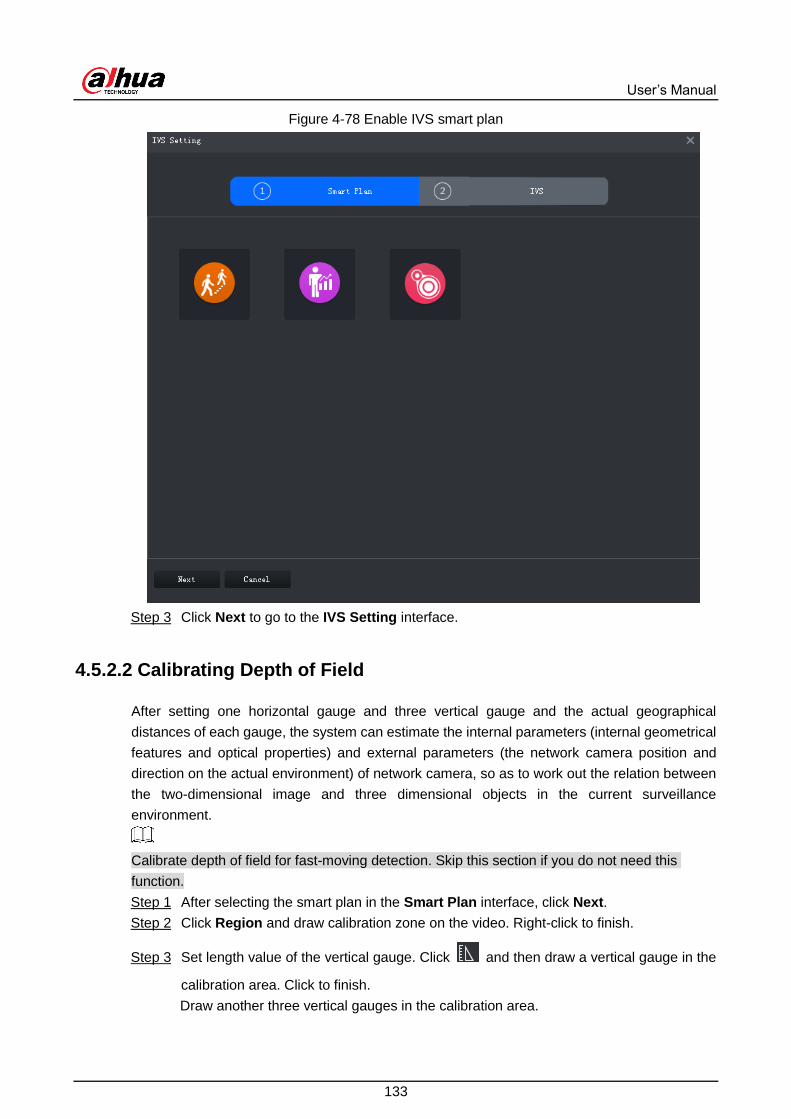
User’s Manual
133
Enable IVS smart plan Figure 4-78
Click Next to go to the IVS Setting interface. Step 3
4.5.2.2 Calibrating Depth of Field
After setting one horizontal gauge and three vertical gauge and the actual geographical
distances of each gauge, the system can estimate the internal parameters (internal geometrical
features and optical properties) and external parameters (the network camera position and
direction on the actual environment) of network camera, so as to work out the relation between
the two-dimensional image and three dimensional objects in the current surveillance
environment.
Calibrate depth of field for fast-moving detection. Skip this section if you do not need this
function.
After selecting the smart plan in the Smart Plan interface, click Next. Step 1
Click Region and draw calibration zone on the video. Right-click to finish. Step 2
Set length value of the vertical gauge. Click and then draw a vertical gauge in the Step 3
calibration area. Click to finish.
Draw another three vertical gauges in the calibration area.

User’s Manual
134
Calibrating depth of field Figure 4-79
Set length value of horizontal gauge. Click and then draw a horizontal gauge in the Step 4
calibration area. Click to finish.
To modify the gauge, you can select it and click Re-draw. You can also select the
calibration and click Re-draw to draw new calibration areas and gauges.
To delete a gauge, select it and click Delete. To delete a calibration area and the
gauges in it, select the area and click Delete.
Click Apply to save. Step 5
(Optional) Vertical/horizontal measuring Step 6
Do the following steps to measure distance.
Click V-Measure and draw vertical line in the calibration area. The measuring
result will be displayed.
Click H-Measure and draw horizontal line in the calibration area. The measuring
result will be displayed.
4.5.2.3 Configuring Detection Region
Configure the detection zone of IVS.

User’s Manual
135
Click . Step 1
Click Detection Zone, and then draw the frame of the detection zone on the video and Step 2
right-click to finish.
Click Excluded Zone, and then draw the frame of the zone on the video and right-click Step 3
to finish.
Detection region Figure 4-80
4.5.2.4 Configuring IVS Rule
Configure IVS detections such as fence-crossing, tripwire, intrusion, abandoned object,
loitering detection, fast-moving, crowd gathering, missing object and parking detection.
Functions Description Applicable Scenarios
Fence-crossing
Alarm is triggered when a
target is crossing the
pre-defined fence.
Roads, airports and other
areas with restricted zones.
Tripwire
Alarm is triggered when a
target is crossing the
pre-defined tripwire.
Restricted zone borders

User’s Manual
136
Functions Description Applicable Scenarios
Intrusion
Alarm is triggered when a
target is entering, leaving, or
appears in the detection
area.
Restricted zone borders
Abandoned Object
Alarm is triggered when an
object is left in the detection
area and the existence time
is longer than the threshold.
Places where the target is
sparse and has no obvious
and frequent light changes.
The detection area is
required to be as simple as
possible. Missing Object
Alarm is triggered when an
object is removed from the
detection area and not put
back after the pre-defined
time period.
Fast-moving
Alarm is triggered when the
moving speed of a target
exceeds the threshold.
Places with low target
density and no obvious
blocking. The camera should
be installed right above the
monitoring area, and the
light direction is as vertical
as possible with the direction
of motion.
Parking Detection
Alarm is triggered when a
target remains still within a
time period longer than the
pre-defined time duration.
Road monitoring and traffic
management.
People Gathering
Alarm is triggered when
people gathering is detected
or people density is larger
than the threshold.
Long or medium distance
monitoring. For example,
outdoor squares,
government gates, and
station entrances and exits.
Loitering
Alarm is triggered when a
target keeps loitering in a
time period longer than the
threshold. Alarm will be
triggered again if the target
stays in the detection area
after the first alarm.
Enterprise zones, halls and
more.
4.5.2.4.1 Tripwire
When a target is detected crossing a line, an alarm will be triggered immediately.

User’s Manual
137
On the IVS Setting interface, click Rule config. Step 1
Rule configuration interface Figure 4-81
Click Add rule. Step 2
Enable rule and modify the name and type. Step 3
1) Enable rule. indicates rule is enabled.
2) Modify rule name.
3) Select Tripwire in the drop-down list of Rule type.
Draw a line on the video and right-click to finish. Step 4

User’s Manual
138
Tripwire Figure 4-82
Set parameters, arming schedule and alarm linkage. Step 5
1) Click Config and set parameters.
Set parameters Figure 4-83
Table 4-29 Parameters
Parameter Description
Object Type Only human or vehicle can trigger alarm.
Direction When the target is moving in the rule direction, it is an intrusion.
Directions include A→B, B→A and A↔B.
2) Click Arming schedule, select day and hours and then set the start time and end
time.

User’s Manual
139
The default arming schedule is 24 hours per day.
Arming schedule Figure 4-84
3) Click Alarm, and then set linkage actions.

User’s Manual
140
Alarm linkage Figure 4-85
Table 4-30 Parameters
Parameter Description
Alarm Output
Connect alarm output devices to the
alarm output interfaces. When an alarm
is triggered, the system will send the
alarm to the alarm output device.
Click Set next to Alarm
Latch and select an alarm
output channel.
Alarm Latch The alarm output action will delay
stopping after the alarm event ends.

User’s Manual
141
Parameter Description
Record
When an alarm happens, it will trigger
video recording immediately.
It requires the device to have recording
schedules already. See device manual
for detailed instruction.
Click Set next to Record
and select an alarm output
channel.
Record Delay Video recording delays stopping for a
while after the alarm event ends.
snapshot
The system will take snapshots
automatically when an alarm happens.
It requires the device to have snapshot
schedules already. See device manual
for detailed instruction.
Click Set next to Snapshot
to select the snapshot
channel.
Send Email
The system will send an email to the
related mail address when an alarm
happens.
It requires the device to have email
configured already. See device manual
for detailed instruction.
–
4) Click Save.
Draw target-filtering frame. Step 6
The filtering frame is used to filter targets that are too big or too small. When the target
size is within the preset value, it can trigger alarm.

User’s Manual
142
Target filtering Figure 4-86
1) Click Target Filter.
2) Select Enable.
3) Select a filtering method, Width or Height or Width and Height. Select filtering
frame and drag the frame corners to adjust the size.
Select filtering frame, and click Clear to delete it.
Click Apply. Step 7
4.5.2.4.2 Intrusion
When a target is detected entering or leaving an area, an alarm will be triggered.
On the IVS Setting interface, click Rule config. Step 1
Click Add rule. Step 2
Enable rule and modify the name and type. Step 3
1) Enable rule. indicates rule is enabled.
2) Modify rule name.
3) Select Intrusion in the drop-down list of Rule type.
Draw a detection zone on the video and right-click to finish. Step 4

User’s Manual
143
Intrusion Figure 4-87
Set parameters, arming schedule and alarm linkage. Draw a target-filtering frame. See Step 5
"4.5.2.4.1 Tripwire."
Set parameters Figure 4-88
Table 4-31 Parameters
Parameter Description
Object Type Only human or vehicle can trigger alarm.
Action List Appear and cross

User’s Manual
144
Parameter Description
Direction When a crossing-zone action is selected, Direction setting will be
effective. Direction includes entering zone, leaving zone and two-way.
Click Apply. Step 6
4.5.2.4.3 Abandoned Object
When an object appears and stays in the detection area for a time period, system will trigger an
alarm.
On the IVS Setting interface, click Rule config. Step 1
Click Add rule. Step 2
Enable rule and modify the name and type. Step 3
1) Enable rule. indicates rule is enabled.
2) Modify Rule name.
3) Select Abandoned Object in the drop-down list of Rule type.
Draw a detection zone on the video and right-click to finish. Step 4
Abandoned Object Figure 4-89
Set parameters, arming schedule and alarm linkage. Draw a target-filtering frame. See Step 5
"4.5.2.4.1 Tripwire."

User’s Manual
145
Set parameters Figure 4-90
Table 4-32 Parameters
Parameter Description
Min Duration The minimum time period between appearing and alarm triggering.
Click Apply. Step 6
4.5.2.4.4 Fast-Moving
When a target appears and its moving speed is or exceeds the preset value for the preset time
period, system will trigger an alarm.
To ensure the accuracy of fast-moving detection, Make sure that you have completed the
calibration configuration. See "4.5.2.2 Calibrating Depth of Field for details."
On the IVS Setting interface, click Rule config. Step 1
Click Add rule. Step 2
Enable rule and modify the name and type. Step 3
1) Enable rule. indicates rule is enabled.
2) Modify rule name.
3) Select Fast-Moving in the drop-down list of Rule type.
Draw a detection zone on the video and right-click to finish. Step 4

User’s Manual
146
Fast-moving Figure 4-91
Set parameters, arming schedule and alarm linkage. Draw a target-filtering frame. See Step 5
"4.5.2.4.1 Tripwire."
Set parameters Figure 4-92
Table 4-33 Parameters
Parameter Description
Object Type Only human or vehicle can trigger alarm.
Min Duration The minimum duration of fast-moving in the detection zone.
Sensitivity It is recommended to keep the default value.
Click Apply. Step 6

User’s Manual
147
4.5.2.4.5 Parking Detection
When a vehicle is detected parking in an area, an alarm will be triggered.
On the IVS Setting interface, click Rule config. Step 1
Click Add rule. Step 2
Enable rule and modify the name and type. Step 3
1) Enable rule. indicates rule is enabled.
2) Modify rule name.
3) Select Parking Detection in the drop-down list of Rule type.
Draw a detection zone on the video and right-click to finish. Step 4
Parking detection Figure 4-93
Set parameters, arming schedule and alarm linkage. Draw a target-filtering frame. See Step 5
"4.5.2.4.1 Tripwire."

User’s Manual
148
Set parameters Figure 4-94
Table 4-34 Parameters
Parameter Description
Min Duration The minimum time duration from parking to alarm triggering.
Click Apply. Step 6
4.5.2.4.6 Crowd Gathering
When the people crowd size in the detection zone exceeds the preset value, system will trigger
an alarm.
On the IVS Setting interface, click Rule config. Step 1
Click Add rule. Step 2
Enable rule and modify the name and type. Step 3
1) Enable rule. indicates rule is enabled.
2) Modify rule name.
3) Select Crowd Gathering in the drop-down list of Rule type.
Draw a detection zone on the video and right-click to finish. Click the Min Gathering Step 4
Region and drag the zone corners to adjust the size.

User’s Manual
149
Crowd gathering Figure 4-95
Set parameters, arming schedule and alarm linkage. Draw a target-filtering frame. See Step 5
"4.5.2.4.1 Tripwire."
Set parameters Figure 4-96
Table 4-35 Parameters
Parameter Description
Min Duration The minimum duration from the time crowd gathering being detected to
alarm triggering
Report Interval If the event still exists after the first alarm, system will trigger more
alarms by the preset alarm interval.
Sensitivity It is recommended to keep the default value.
Click Apply. Step 6

User’s Manual
150
4.5.2.4.7 Missing Object
If an object has been moved out of the detection zone and not put back anymore for a certain
time period, system will trigger an alarm.
On the IVS Setting interface, click Rule config. Step 1
Click Add rule. Step 2
Enable rule and modify the name and type. Step 3
1) Enable rule. indicates rule is enabled.
2) Modify rule name.
3) Select Missing Object in the drop-down list of Rule type.
Draw a detection zone on the video and right-click to finish. Step 4
Missing object Figure 4-97
Set parameters, arming schedule and alarm linkage. Draw a target-filtering frame. See Step 5
"4.5.2.4.1Tripwire."

User’s Manual
151
Set parameters Figure 4-98
Table 4-36 Parameters
Parameter Description
Min Duration The minimum time duration from object disappearing to alarm
triggering.
Click Apply. Step 6
4.5.2.4.8 Loitering Detection
When a target stays in the detection zone after appearing for a certain time period, an alarm will
be triggered.
On the IVS Setting interface, click Rule config. Step 1
Click Add rule. Step 2
Enable rule and modify the name and type. Step 3
1) Enable rule. indicates rule is enabled.
2) Modify rule name.
3) Select Loitering Detect in the drop-down list of Rule type.
Draw a detection zone on the video and right-click to finish. Step 4

User’s Manual
152
Loitering detection Figure 4-99
Set parameters, arming schedule and alarm linkage. Draw a target-filtering frame. See Step 5
"4.5.2.4.1 Tripwire."
Set parameters Figure 4-100
Table 4-37 Parameters
Parameter Description
Min Duration The minimum time duration from target appearing to alarm triggering.
Report Interval If the event still exists after the first alarm, system will trigger more
alarms by the preset alarm interval.
Click Apply. Step 6

User’s Manual
153
4.5.2.5 Setting Parameters
Set common parameters for the IVS, including disturbance filter and sensitivity.
Click Parameters after configuring rules in the Rule config interface. Step 1
Set parameters. Step 2
Parameters Figure 4-101
Table 4-38 Parameters
Parameter Description
Disturbance
Filter
Filter false targets including waving plants and water waves. This function
may cause target omissions as some parts of a true target may be judged
as false factors.
Sensitivity
Control detection sensitivity. The smaller the value is, the lower the false
detection rate will be and the higher omission rate will happen. The bigger
the value is, the higher false detection rate will be and the lower the
omission rate will happen.
Click Save. Step 3

User’s Manual
154
Fisheye-PTZ Smart Track 4.6
Link a PTZ camera to a fisheye camera so that when the fisheye camera detects a target, the
PTZ camera automatically rotates to it and track.
4.6.1 Typical Topology
Fisheye and PTZ smart track topology Figure 4-102
Fisheye camera is used to monitor the whole view. PTZ camera is used to track the target
and capture details.
DSS Pro is used to manage all cameras, configure smart track, and view live video. It
supports PTZ operations, snapshot and video recording.
DSS Pro
Network
Cable
球机
鱼眼相机
Switch
Speed Dome
Fisheye

User’s Manual
155
4.6.2 Business Flow
Fisheye-PTZ smart track Figure 4-103
4.6.3 Configuring Fisheye-PTZ Smart Track
4.6.3.1 Preparations
Make sure that the following preparations have been made:
Fisheye camera and PTZ camera are well deployed. To deploy, see the corresponding
user's manuals.
Basic configurations of the platform have been finished. To configure, see "3 Basic
Configurations."
When adding cameras, select Encoder for Device Category. See Figure 4-104.

User’s Manual
156
Set device category Figure 4-104
On the Device interface of Web Manager, after the fisheye camera is added, click
of it, and select Fisheye in the Features drop-down list.
Set fisheye camera features Figure 4-105
4.6.3.2 Configuring Fisheye-PTZ Smart Track
On the homepage of Control Client, select Live View. Step 1
From the device tree on the left, right-click on a fisheye camera, and then select Smart Step 2
Track.

User’s Manual
157
If it is not the first time to use the smart track function, select the fisheye camera,
right-click, and then select Smart Track Modify.
Set smart track rules (1) Figure 4-106
Click after the Select linkage PTZ camera and then select a PTZ camera. Step 3
Click and then move the of the fisheye on the right to select a position. Step 4
Click on the general PTZ camera to find the position. Adjust the PTZ camera to
find the position and move the PTZ to the center position (The green cross on the
image).

User’s Manual
158
Set smart track rules (2) Figure 4-107
Select 3-8 mark points on fisheye camera.
When you find mark point on the left side of general PTZ camera, click to
zoom out PTZ.
Click to 3D position, and when you click a certain point on the left side of
PTZ camera, it will automatically move to the center.
Click to save the calibration point. Step 5
See above steps to add at least three calibration points. These three points shall not be
on the same straight line.
Click Save. Step 6
4.6.4 Applying Fisheye-PTZ Smark Track
On the homepage of Control Client, select the fisheye device on the device tree and Step 1
then right-click to select Smart Track.

User’s Manual
159
Select a smart track channel Figure 4-108
Click any point on the left of fisheye, general PTZ camera on the right will auto link to Step 2
corresponding position
Click , system pops up Save View box. Step 3
Save view Figure 4-109
Enter view name, select group, and click OK. Step 4
Bullet-PTZ Smart Track 4.7
When a target is detected in the bullet camera view, the PTZ camera can automatically go to
track the target.

User’s Manual
160
4.7.1 Typical Topology
Bullet-PTZ smart track topology Figure 4-110
You can use the panoramic + PTZ camera, starlight smart capture camera, bullet-PTZ
camera or separate bullet camera and PTZ camera for bullet -PTZ smart track.
Bullet camera is used to monitor the whole view. PTZ camera is used to track the target
and capture details. DSS Pro is used to manage all cameras, configure smart track, and
view live video. It supports PTZ operations, snapshot and video recording.
4.7.2 Business Flow
Bullet-PTZ smart track Figure 4-111
DSS Pro
IPC球机
Bullet Camera and PTZ Camera Bullet-PTZ CameraPanoramic+PTZ CameraSmart Capture Camera
Switch
Network Cable

User’s Manual
161
4.7.3 Configuring Bullet-PTZ Smart Track
4.7.3.1 Preparations
Make sure that the following preparations have been made:
Cameras are well deployed. To deploy, see the corresponding user's manuals.
Basic configurations of the platform have been finished. To configure, see "3 Basic
Configurations." During configuration, note that:
When adding cameras, select Encoder for Device Category.
Set device category Figure 4-112
On the Device interface of Web Manager, click of the bullet camera, starlight
smart capture camera, or panoramic + PTZ camera, and then select Master Slave
Track for Features.

User’s Manual
162
Set camera features Figure 4-113
4.7.3.2 Configuring Bullet-PTZ Smart Track Settings
Relate bullet camera view to PTZ camera view. Skip this section if you use panoramic + PTZ
camera.
Single-sensor bullet camera
Select two views to calibrate coordinates, 4 coordinates for each view.
Multi-sensor bullet camera
Calibrate one view for each sensor of the camera, 4 coordinates for each view.
Log in to the Control Client, click , and then select Live View. Step 1
In the device tree, right-click the bullet camera, and then select Master-slave Config to Step 2
open the device login interface.
Master slave config Figure 4-114
On the device login interface, set bullet camera and PTZ camera parameters. Step 3

User’s Manual
163
Separate mode: The bullet camera and PTZ camera are separate. Their login
information is different. The bullet camera information is already displayed. Specify
PTZ camera information as needed.
Bullet-PTZ camera: The bullet camera and PTZ camera are integrated in one
camera. Their login information is the same.
Click Login and Link to open the smart track calibration interface. Step 4
Use the PTZ control panel to rotate the PTZ camera view on the left side to the position Step 5
where the bullet camera is overlooking.
Click Start. Step 6
During the calibration, PTZ control is unavailable to ensure accuracy of calibration. To
operate PTZ during the calibration, click Pause. To resume calibrating, click Start.
Calibrate coordinates. Step 7
1) Click Add next to Coordinate 1, and then two frames appear in the bullet view.
Move the two frames to the same positions, and then the coordinate values appear
in the boxes of the Coordinate 1.
2) Repeat the previous step to finish the remaining 3 coordinate groups.
3) Click Save.
4) Click OK on the confirmation dialogue box.
If the bullet camera is multi-sensor, the next calibration view is displayed.
If the bullet camera is single-sensor, the next coordinate-group calibration
interface is displayed.
5) Complete the calibration of all coordinates.
The Apply button is highlighted on the finishing interface.
6) Click Apply.
4.7.4 Applying Bullet-PTZ Smart Track
Smart track application includes manual positioning, 3D positioning, manual tracking, auto
tracking and preset return.
4.7.4.1 Manual Positioning
Click any position on the bullet image, and the PTZ will position the image to the area
designated by bullet due to smart track. Click the red spot on the bullet image, and the PTZ
central point will move to the corresponding location automatically.

User’s Manual
164
Manual positioning Figure 4-115
4.7.4.2 3D Positioning
Select an area on the bullet image, and the PTZ camera will position the image to the
corresponding area, meanwhile zoom in or out.
Draw rectangular box from upper left to lower right, zoom in after being positioned by PTZ
camera.
Draw rectangular box from lower right to upper left; zoom out after being positioned by PTZ
camera.

User’s Manual
165
3D positioning (1) Figure 4-116

User’s Manual
166
3D positioning (2) Figure 4-117
4.7.4.3 Manual Track
Bullet PTZ all-in-one camera, panoramic + PTZ camera and individual bullet have been
configured with smart rules. For detailed operation, see device user manual.
IVS Overlay is required to be selected on the bullet image, enable target box overlay.
Target box will be displayed only when there is moving target appears in the image.
Manual track priority is higher than auto track.

User’s Manual
167
Click moving target box (valid inside the box as well) in the bullet monitoring image, and the
color of target box changes, PTZ camera will track the selected target.
Manual track Figure 4-118
4.7.4.4 Auto Track
After auto track is enabled, when there is target triggering IVS rule in the bullet image, then PTZ
camera will automatically track the target that triggers IVS rule. If there are more than two
tracking targets in the image, then it will select tracking target according to trigger time.
Bullet PTZ all-in-one camera, panoramic + PTZ camera and individual bullet have been
configured with smart rules. For detailed operation, see device user manual.

User’s Manual
168
IVS Overlay is required to be selected on the bullet image, enable target box overlay.
Target box will be displayed only when there is moving target appears in the image.
Manual track priority is higher than auto track.
In the device list on Live interface, select individual bullet, bullet PTZ all-in-one camera or
panoramic + PTZ camera, right-click and select Auto Track > On and enable auto track. When
there is moving target in the image, then PTZ camera will track the target automatically.
Select automatic track Figure 4-119

User’s Manual
169
Automatic track Figure 4-120
4.7.4.5 Preset Return
Enable preset return when idle during calibration, in any status, when there is no target
triggering track within the specific period on the bullet image, then PTZ image will return to the
designated preset.

User’s Manual
170
Radar-PTZ Smart Track 4.8
When the radar detection zone is intruded, the associated PTZ camera will track this target
automatically.
The interface pictures in this section might vary depending on the radar device type, and the
actual interface shall prevail.
4.8.1 Typical Topology
Radar-PTZ smart track topology Figure 4-121
Radars detect and tracks targets.
The speed domes collect videos and follows the targets.
DSS Pro is used to manage radars and cameras, configure smart track, and view live
video. It supports PTZ operations, snapshot and video recording.
In addition to radar and speed dome, you can also use the radar + PTZ camera for the smart
track.

User’s Manual
171
4.8.2 Business Flow
Radar-PTZ smart track business flow Figure 4-122
4.8.3 Configuring Radar-PTZ Smart Track
4.8.3.1 Preparations
Make sure that the following preparations have been made:
Radars and cameras are well deployed. To deploy, see the corresponding user's manuals.
Basic configurations of the platform have been finished. To configure, see "3 Basic
Configurations." During configuration, note that:
When adding a radar, select Radar as its device category.
When adding a radar + PTZ camera, select Encoder as its device category, and then
select Smart Track (Radar + PTZ) in the Features drop-down list for its video
channel.

User’s Manual
172
Modify device features Figure 4-123
4.8.3.2 Configuring Radar-PTZ Smart Track
Configure map. The map displays device and target locations. You can also view the
associated live videos on the map.
On the Homepage of the Control Client, select Radar Smart Track. Step 1
Add a map picture. Step 2
You can add up to 10 maps.
1) Click .
2) Enter map name, and then click to select a picture.
Support the .png, .jpg and.jpeg picture formats.

User’s Manual
173
Add a map Figure 4-124
3) Click OK.
Calibrate. Step 3
Calibrate map distance with the actual geographical distance to ensure the accuracy of
radar measuring. Make sure to select a definite distance to calibrate.
1) Draw a distance on the map.
The Map Setting interface is displayed by default after a map picture is imported.
You can also click Map Setting to get into this interface.

User’s Manual
174
Calibrate Figure 4-125
2) Enter the real geographical distance of the drawn line, and then click OK.
The line turns into yellow.
3) Click OK.
4) (Optional) click the icon on the left of the Radar Smart Track interface to set
the corresponding map as the main map.
If there are multiple maps, the main map is displayed on the Radar Smart Track
interface by default. indicates that the map is a main map.
Set the main map Figure 4-126
Add devices. Step 4
1) Click Radar Relation.
2) Select a device in the Radar drop-down list, and then drag it to the actual location
on the map.
3) Set the X and Y coordinates values for the radar location.

User’s Manual
175
4) Set radar Orientation value or click and to adjust the orientation. 10
degrees for each click.
The horizontal direction is 0 degree by default.
The radar angle and radar radius values are automatically obtained from the
device.
The Calibration button is not available now.
Click Interface to view PTZ camera video. The radar view is displayed at the
upper-left corner of the PTZ video.
Add a radar relation Figure 4-127
(Optional) Bind PTZ camera. Step 5
If you are using general radar, you need to bind a PTZ camera for it.
1) Click Radar Relation.
2) On the Add radar relation interface, click Setting, and then click Binding config.
3) Select a PTZ camera, and then click OK.
You can select multiple PTZ cameras to bind to the radar.
The Alarm Track function is enabled by default after the binding
configuration.

User’s Manual
176
Bind PTZ camera Figure 4-128
4) Enable or disable Alarm Track as needed.
When Alarm Track is enabled and radar and PTZ have been calibrated, the
automatic tracking is triggered once the radar detection zone is intruded.
Calibrate radar and PTZ camera to make sure that they are consistent in geographic Step 6
information.
1) On the Radar PTZ Config interface, click the Device Calibration tab.
2) Confirm PTZ camera information, and then click OK to log in to PTZ.
PTZ video is displayed on the right.

User’s Manual
177
Device calibration Figure 4-129
3) Set the values of InstallHeight and LinkSDHeight. They are the real values of the
height where the radar and speed dome camera (PTZ camera) are mounted.
4) Click , and then on the radar view on the left, click the target position. On the
PTZ camera video, operate the PTZ control panel to rotate the PTZ view to that
target position.
Click next to Linkage Tracking to disable the function before the calibration;
otherwise the view might be unstable. indicates that the function is disabled.
5) Click Apply.
Manage areas. Step 7
Set alarm area, shielding area, and pre-warning area.
1) On the Radar PTZ Config interface, click the Area Management tab.
2) Click to add an area. Click and then draw the area on the map.
On the map, click to start drawing, and then right-click to finish.

User’s Manual
178
Area management Figure 4-130
3) Set parameters.
Table 4-39 Area rule description
Parameter Description
Name Name of rule.
Double-click to modify the default rule name.

User’s Manual
179
Parameter Description
Type
Area type includes:
Alarm area: In an alarm area, when a target is detected, the target
moving track is displayed, and the PTZ camera is linked to track the
target, and there will be an alarm for warning. Targets outside of the
alarm area will have only the moving tracks, but the PTZ cameras will
not follow and there is no alarm.
Shielding area: A target in a shielding area is not displayed with a
moving track or followed by the PTZ camera. A target outside of the
shielding area will have a moving track and be followed by the PTZ
camera, in addition to which, there will also be an alarm for warning.
Pre-warning area: It has the same function with the alarm area, but
with lower priority.
An alarm area is generally inside a pre-warning area. In this way, the
detected target triggers a warning first in the pre-warning area, and then
when it enters the alarm area, an alarm will be triggered.
In the radar view, if there is no alarm area, targets are displayed with
moving tracks and followed by PTZ cameras, but there will be no
alarm.
In the radar view, if there are targets both in and outside the alarm
area, the PTZ camera only tracks the one inside the alarm area.
In the radar view, in the overlapped section of the alarm area,
shielding area and pre-warning area, targets are displayed with
moving tracks and followed by PTZ camera, and trigger alarms.
4) Click Apply.
Configure radar settings. Step 8
1) On the Radar PTZ Config interface, click the Radar Setting tab.
2) Set tracking parameters.

User’s Manual
180
Radar setting Figure 4-131
Table 4-40 Parameters description
Parameter Description
Track Mode Set track mode and time duration as needed.
Tour: According to the linkage tracking duration setting, switch to
another target after a few seconds.
Time Priority: Follow the target which appears earliest into the
radar view.
Location Priority: Follow the target closest to the radar.
Linkage Tracking
Trajectory
Duration Set the time length of the dispalyed moving track.
Select Channel Select a radar frequency band to avoid interference.
Environment Mode Select a suitable environment mode. Different environments adopts
different algorithms for the best effect.
Tracking Target
Display Set the size of target displayed on the PTZ view during tracking.
3) Click OK.
4.8.4 Radar-PTZ Smart Track Monitoring
On the Homepage interface of the Control Client, select Radar Smart Track. Step 1

User’s Manual
181
On the map, if the radar device has an alarm, the radar point flashes red.
Click Structured Data at the upper-right corner of the Radar Smart Track
interface to enable structured data display, and then the targets inside the alarm
area are displayed with features information on the map.
Radar-PTZ smart track (1) Figure 4-132
Click the radar icon on the map. Step 2

User’s Manual
182
Radar-PTZ smart track(2) Figure 4-133
Support the following operations:
Click , and then the live video is displayed.
Live video Figure 4-134
Click , and then the Add radar relation interface is displayed. You can add
more devices onto the map. For details, see "3.7.1 Adding Map."
Click to delete radar.
Click to cancel alarms.

User’s Manual
183
Record 4.9
You can search and play back records stored in the device or the platform.
4.9.1 Preparations
Encoders such as cameras and NVRs or DVRs are well deployed.
DSS Pro is well deployed. For details, see "3 Basic Configurations."
The device or DSS Pro has recorded videos.
4.9.2 Playback
Play back recorded videos.
4.9.2.1 Playing Back Recorded Videos
Log in to Control Client, and then select Record Playback. Step 1
Playback interface Figure 4-135
Table 4-41 Description
Icon Description
Lock the video stored on server within some period of
designated channel. Locked video will not be overwritten
when disk is full.

User’s Manual
184
Icon Description
Cut video
Download video
Filter video according to record type.
Make dynamic detection analysis over some area of the
record image, it only replays the video with dynamic image
in the detection area.
Playback record files of the same period from different
channels on selected windows.
Stop/pause playback
/ Frame by frame playback/frame by frame backward.
Fast/slow playback. Max. supports 64X or 1/64X.
During playback, you can drag time progress bar to play
back record at the specific time.
Select a channel on the device tree. Step 2
Select date and record storage position. Click Search. Step 3
Blue dots on the calendar indicate existence of video files.
Select a window that has video and then click to play. Step 4
Hover over the video, and then the icons appear. You can perform the following actions. Step 5
Video playback Figure 4-136
Table 4-42 Description

User’s Manual
185
Icon Name Description
Tag Tage the videos of interest for easy search in the future. For details,
see "4.9.2.5 Tagging Videos."
Local
Recording
Click this icon to start recording. The recorded video is stored
locally. The saving path is "C:\DSS Pro\Client\Record\" by default.
To modify the path, see "4.1.4 Local Configuration."
Snapshot
Take a snapshot of the current image and save it locally. The saving
path is "C:\DSS Pro\Client\Picture\" by default. To modify the path,
see "4.1.4 Local Configuration."
Zoom Select a section to zoom it in for viewing details.
Close Close the window
● Right-click the video, and then you can perform the following actions.
The shortcut menu varies depending on the camera functionality. The actual shall
prevail.
Shortcut menu Figure 4-137
Table 4-43 Description
Name Description
Close Close the current video window.
Close All Close all video windows.
Start Local
Record
Record audio and video of the current video window and save them
locally.

User’s Manual
186
Name Description
Audio Input
Selection
If the camera has more than one audio input channels, you can select
one or select the mixed audio. This configuration is effective with both
live view and playback.
Snapshot
Take a snapshot of the current image (one picture for each snapshot
action). The default saving path is: C:\DSS Pro\Client\Picture\. To modify
the path, see "4.1.4.4 Configuring Snapshot Settings."
Continuous
Snapshot
Take a snapshot of the current image (three snapshots each time by
default).
Video
Adjustment Perform video adjustment and video enhancement.
IVS Overlay
The client does not show overlay lines over live video by default. When
needed, you can click AI Overlay and enable Rule Overlay and Target
Box Overlay, and then the live video shows overlay lines if the AI
detection rules are enabled on the device. This configuration is effective
with the current selected channel both in live view and playback.
SMD Overlay
Enable SMD Overlay to show target frame over live video. When SMD is
enabled on the device, you can enable SMD Overlay for the device
channel, and then the live video will display dynamic target frames. This
configuration is effective with the current selected channel both in live
view and playback.
Disable Privacy
Masking
For a camera that supports privacy masking of human face, you can
disable the masking here to view the face image.
Playback on
Wall
Play the current channel on video wall. For configuration of video wall,
see "4.10 Video Wall."
Full Screen Switch the video window to full screen mode. To exit full screen,
double-click video window, or right-click to select exit full screen.
Switch to
Preview Go to live view.
4.9.2.2 Record Type Filter
Filter video according to record type, record type includes schedule record; alarm record and
motion detect record.
Log in to Control Client, and then select Record Playback. Step 1
On Record Playback interface, set search conditions to search for videos. Select a Step 2
window that has videos, and then click .

User’s Manual
187
Record playback interface Figure 4-138
Record type filter Figure 4-139
Select a record type (or types) and then click OK. Step 3
The system only displays the video of selected type.
4.9.2.3 Smart Search
With the Smart Search function, you can select a zone of interest on the video image to view
motion records within this section. The relevant camera is required to support Smart Search;
otherwise the search result will be null.
Log in to Control Client, and then select Record Playback. Step 1
On Record Playback interface, set search conditions to search for videos. Select a Step 2
window that has videos. Click , and then select a type.
The smart search interface is displayed. 22×18 squares are displayed in the window.

User’s Manual
188
Enable smart search Figure 4-140
Smart search Figure 4-141
Click the squares and select detection areas. Step 3
Select detection area; Move the mouse pointer to image, press mouse left button
and drag the mouse to select square.
For selected area, click again or select square to cancel it.
Click and start smart search analysis. Step 4
If there is search result, the time progress bar will become purple and display
dynamic frame.
If there is no search result, or selected playback device fails to support smart
search, then it will prompt that smart search result is null.

User’s Manual
189
Click and you can reselect detection area.
Click the play button on the image or control bar. Step 5
The system plays search results. The search results are marked purple on the on the
timeline.
Click to exit Smart Search. Step 6
4.9.2.4 Locking Videos
Lock the video stored on the server within some period of specific channel. The locked video
will not be overwritten when disk is full.
You can only lock the central video stored on the server.
Log in to Control Client, and then select Record Playback. Step 1
Set search conditions and then click search. Select a window that has recorded video, Step 2
and then click at the bottom of the Record Playback interface, and then click on
the timeline to mark the start point and end point of the video clip you need.
Lock record Figure 4-142
Confirm the start and end time, and then click OK. Step 3
4.9.2.5 Tagging Videos
You can tag records of interest for quick search.

User’s Manual
190
Log in to Control Client, and then select Record Playback. Step 1
On Record Playback interface, move the mouse pointer to the window that is playing Step 2
record. Click at the upper-left corner.
Tag a video Figure 4-143
Name the tag, and then click OK. Step 3
4.9.2.6 Clipping Videos
Log in to Control Client, and then select Record Playback. Step 1
Click at the bottom of the Record Playback interface (Make sure that there is Step 2
record in the window).
On the timeline, click to select the start and end time. Step 3
Save download Figure 4-144
Set file format and then click OK. Step 4
4.9.2.7 Downloading Videos
You can download the videos of interest stored in the server or the device. The downloaded
videos are in .avi, mp4, or .asf format.
Three ways to download videos:

User’s Manual
191
Download clipped videos from the timeline.
Download video files from the file list.
Download videos by searching video tags.
Click on the Record Playback interface, or click and then select Download Step 1
Center.
Set search conditions, and then click Search. Step 2
Download center Figure 4-145
Select videos to download. Step 3
To download videos by clipping the timeline, click the Timeline tab, and then select
the start and end time of the video clip by clicking on the timeline.
To download videos by selecting the searched video files, click the File tab, and
then click .
To download tagged videos, click the Tag tab, and then click .
In the password verification dialogue box that appears, enter the password, and then Step 4
click OK.
In the Record Download dialogue box, confirm the time span, and then, if necessary, Step 5
click to select a video format. Click OK.
The download progress is displayed. During the download process, you can pause,
stop and cancel the download task by clicking the corresponding icons.
4.9.3 POS Search
Search for POS receipts, and view related videos. Support displaying videos starting from half
an hour before the receipt printing moment. The maximum length is 24 hours. The video is
played from 30 seconds prior to the receipt printing moment. For details, see "4.14 POS."

User’s Manual
192
4.9.4 Searching by Thumbnail
Divide the searched video into levels and display in the form of thumbnail, which is the select
ROI. You can view the searched video and image change of ROI at different time, and realize
fast search.
Log in to Control Client, and then select Record Playback. Step 1
On Record Playback interface, click . Step 2
Thumbnail Figure 4-146
In the organization tree, select a video channel and then set search period and record Step 3
position. Click .
There is a blue dot at the top-left corner of the date if the channel has record files. See
Figure 4-147.

User’s Manual
193
Select time Figure 4-147
Search result Figure 4-148
Drag the yellow frame on the right to set thumbnail range. Click . Step 4

User’s Manual
194
Thumbnail search Figure 4-149
System displays search results in suitable mode by default. Click Less, suitable,
more to see proper mode.
Double-click the thumbnail, system search again for the record between current
image and the next image.
Click the at the bottom right corner of the thumbnail, you can view the Step 5
corresponding video related to the thumbnail.
Video playback Figure 4-150
Download Record Step 6

User’s Manual
195
If videos of different stream type exist in the download period, then it can only be saved
as .dav.
1) Click at the right corner of the thumbnail, and then system downloads the
record between current image and the next image.
Download video Figure 4-151
2) Select a file format and then click OK.
Go to the Download Center to view download detailed information. For details,
see "4.9.2.7 Downloading Videos."
Video Wall 4.10
A video wall, which is consisted of multiple video screens, is used Control Center for displaying
videos on the wall, instead of small PC displays.
Complete video wall settings before you can view videos on the wall.

User’s Manual
196
4.10.1 Typical Topology
Typical topology Figure 4-152
Cameras (IPC) are used to collect video streams. Some cameras support intelligent
analysis, for example, face recognition.
M60 is a decoder. It converts the digital video signal into analog signal for video display. In
addition to M60 as shown in the topology, you can also use M70 and other decoder
models.
DSS Pro centrally manages all cameras, decoders and controllers. It supports video wall
configuration.

User’s Manual
197
4.10.2 Business Flow
Video wall business flow Figure 4-153
4.10.3 Configuring Video Wall
4.10.3.1 Preparations
To achieve video display on the wall, you need to make sure that:
Cameras, decoders and video wall are well deployed. To deploy, see the corresponding
user's manuals.
Basic configurations of the platform have been finished. To configure, see "3 Basic
Configurations." During configuration, note that:
When adding a camera, select Encoder for Device Category.

User’s Manual
198
Set device category Figure 4-154
When adding a decoder, select Video Wall Control for Device Category.
Add a decoder Figure 4-155
A glimpse of the video wall configuration interface

User’s Manual
199
Video wall interface Figure 4-156
Table 4-44 Description
No. Name Function
1 Device Tree
If you enable Show device node in Local config > Basic, the
device tree will display devices and all channels. If you clear the
Show device node check box, the device tree will only display
channels.
Click to view the channels in the Favorites folder.
Support searching for devices or channels by entering device name
or channel name in .
2 Live View View channel video.
3 Detailed
Information
View the screen, window, and channel bound information.
Click to view live video of the current channel at the bottom
left.
Click to adjust sequence.
Click to delete the video channel on the current window.
Click the Stay Time (s) column or click to modify the video
play duration of the current channel during tour.
Click the Stream column or to modify stream type.
4 Window Split Set window split mode.
5 Clear Clear all screens.

User’s Manual
200
No. Name Function
6 Start/stop All
Tours Start or stop all tours.
7 Lock Window Click to lock the window. Operation is not allowed on a locked
window.
8 Add Box Marked the selected window with a red frame.
9 Back Display View video image of the selected channel window.
10 Screen On/off Turn a screen on or off.
11 Apply Now If you enable the function, system automatically outputs the video to
the wall after you set the task.
12 Decode to
Wall Click it to manually output the video to the wall.
13 Eagle Eye View current video wall layout.
14 Video Wall Video wall area.
15 Video Wall
Task
Configure scheduled tasks and tour tasks. See "4.10.3.4 Video Wall
Plan" for details.
16 Task
Management Add, save or delete a task.
17 Video Wall
Selection Select a video wall.
4.10.3.2 Adding Video Wall
Add a video wall layout on the platform.
Click on the Web Manager, and select Video Wall on the New Tab interface. Step 1
Click Add Video Wall or . Step 2
Enter Video Wall Name, and then select a window splicing mode. Step 3
Select a splicing mode from among 1×1, 2×2, 3×3, 4×4 or set a custom mode
by clicking .
A multi-screen splicing mode is a combined screen by default. You can perform
video roaming on it. For example, with a 2×2 combined screen, if you close 3 of
them, the other one will be spread out on the combined screen. To cancel
combination, click the combined screen, and then click
To create a combined screen, press and hold Ctrl, select multiple screens, and
then click .
To clear the created screen, click.

User’s Manual
201
Add a video wall Figure 4-157
Click Select Channel. Step 4
Select the encoder which needs to be bound in the device tree, and drag it to the Step 5
corresponding screen.

User’s Manual
202
Select a decoding channel Figure 4-158
You can set if it displays ID in the screen, means that
the screen ID has been disabled; click the icon and it becomes
, and then it means that screen ID has been enabled.
Each screen in a combined screen must be bound with a decoding channel.
Click Done. Step 6
4.10.3.3 Configuring Video Wall Display Tasks
Display videos on the wall manually or in accordance with the pre-defined configuration.
Click on the Control Client, and then select Video wall. Step 1
In the Task drop-down list, select Add. Step 2

User’s Manual
203
Add a video wall task Figure 4-159
Click to stop video wall display. Step 3
From the device tree, select a camera, and then drag it to a screen, or select a window, Step 4
drag the camera to the Detail section.
If you do not close video wall display in advance, this action will delete the bound
camera and play the selected camera on the wall.
Click . Step 5
If you have selected an existing task in the Task drop-down list, this action will refresh
the configuration of the selected task. The task will be played on the wall immediately.
Name the task, and then click OK. Step 6
During video wall display of a task, if you have rebound the video channel, click
to start video wall display manual.
During video wall display, click or to stop or start tour display.

User’s Manual
204
4.10.3.4 Configuring Video Wall Plans
4.10.3.4.1 Configuring Timed Plans
Configure a time schedule of tasks, and then you can play the plan on the wall. If the schedule
is not completely filled up with the tasks, you can define other tasks for the empty section.
On the Video Wall interface, click at the upper-right corner. Step 1
Hover over , and then select . Step 2
Set schedule plan Figure 4-160
Enter the plan name. Step 3
Select a video task, set start time and end time, and then click . Step 4
Repeat this step to add more tasks. The start and end time cannot be repeated.
Select the Enable remaining time schedule check box, and then set the task. The
video wall displays the selected task during the remaining period.

User’s Manual
205
Task time Figure 4-161
Click Save. Step 5
Click to start the plan. Step 6
Enable timed plan Figure 4-162
Operations
Modify plan: Click of the corresponding plan, it is to modify plan.,
Delete plan: Click of the corresponding plan, it is to delete the plan.
4.10.3.4.2 Configuring Tour Plans
After setting video wall tasks, you can configure the sequence and interval of tasks so that they
can automatically play in turn on the wall.
On the Video Wall interface, click at the upper-right corner. Step 1
Hover over , and then select . Step 2

User’s Manual
206
Tour plan Figure 4-163
Enter task name, select a video task and then set stay time. Click . Step 3
Repeat this step to add more tasks.
Click to adjust task sequence; click to delete task.
Tour information Figure 4-164
Click Save. Step 4
Click to start the tour plan. Step 5
Enable tour plan Figure 4-165

User’s Manual
207
Operations
Modify plan: Click of the corresponding plan, it is to modify plan.
Delete plan: Click of the corresponding plan, it is to delete the plan.
4.10.4 Video Wall Applications
Make sure that decoder video ports are connected to the video wall screens.
4.10.4.1 Instant Display
Drag a camera to the video wall screen for instant display on the wall.
Log in to the Control Client, click , and then select Video wall. Step 1
In the Video Wall drop-down list, select a video wall. Step 2
Click to start video wall display. Step 3
Drag a camera from the device tree to a screen, or select a window and drag the Step 4
camera to the Detail section.

User’s Manual
208
Bind video channel Figure 4-166
For a fisheye camera, right-click it to select the installation mode for fisheye dewarp.
Select a screen, and then click Detail to view detailed information about the screen and Step 5
channel, including stream type, preset and display sequence.
Click to view live video of the current channel at the bottom left.
Click to adjust sequence.
Click to delete the video channel on the current window.

User’s Manual
209
Set video channel parameters Figure 4-167
4.10.4.2 Video Wall Task Display
Display a pre-defined task on video wall.
Make sure that there are pre-defined tasks.
Log in to the Control Client, click , and then select Video wall. Step 1
In the Task drop-down list, select a task. Step 2
Operations available. Step 3
After changing the video channel that is being displayed, click at the
lower-right corner before you can see the effect on video wall.
Click / to pause or stop.
Select a screen, and then click Detail to view detailed information about the screen
and channel, including stream type, preset and display sequence.
Click to view live video of the current channel at the bottom left.
Click to adjust sequence.

User’s Manual
210
Click to delete the video channel on the current window.
4.10.4.3 Video Wall Plan Display
Display a pre-defined plan on video wall.
Make sure that there are pre-defined plans. For details, see "4.10.3.4 Configuring Video Wall
Plans."
The video wall automatically works as the plans have been configured. To stop the current plan,
click at the upper-right corner of the Video Wall interface, and then it changes to .
Click to start again.
Traffic 4.11
Use this feature for vehicle speed measurement, and traffic violation and vehicle flow search.
Interval speed measurement
Vehicles are detected when they get through the speed measurement locations. According
to distance and time, DSS Pro calculates the average speed of vehicles, and then
determines whether a vehicle is speeding or driving too slow.
Interval speed measurement Figure 4-168
Violation
If a violation is detected at the measurement location, the system will upload the vehicle
information and snapshots to DSS Pro. DSS Pro supports violation records search.
Traffic flow
The cameras at the traffic monitoring locations analyzes traffic situation in the relevant
lanes and uploads the results to DSS Pro. The results are uploaded once per second by

User’s Manual
211
default. And you can modify that frequency on the device (1 to 250 times per second). The
results include the total vehicle volume, average speed, lane occupancy ratio and numbers
of different vehicle types. Vehicle types include car, passenger vehicle, small truck, and
large truck. Vehicle traffic data retention period is at least 2 years.
4.11.1 Typical Topology
Typical topology Figure 4-169
The ITC cameras capture vehicle information.
DSS Pro centrally manages all devices, calculates average speed, triggers speeding or
low-speed alarms, and provides traffic and violation record search.
4.11.2 Business Flow
Traffic monitoring business flow Figure 4-170

User’s Manual
212
4.11.3 Configuring Traffic Monitoring
4.11.3.1 Preparations
Make sure that the following preparations have been made:
ITC cameras are well deployed, and the traffic flow analysis function and violation events
are well configured. For details, see the corresponding user’s manuals.
Basic configurations of the platform have been finished. To configure, see "3 Basic
Configurations."
When adding an ITC camera, select ANPR for device category, and then select ANPR
Device for device Type.
Add ITC camera (1) Figure 4-171

User’s Manual
213
Add ITC camera (2) Figure 4-172
The vehicle snapshots are only stored in the ANPR Picture disks. On the Storage
interface, configure at least one ANPR Picture disk. Otherwise vehicle pictures
cannot be viewed.
Disk type Figure 4-173
4.11.3.2 Configuring Location
Configure locations for speed measurement. One location is equipped with one or more ANPR
cameras.
Click on the Web Manager, and then select Average Speed on the New Tab Step 1
interface.
Click the Location Config tab. Step 2

User’s Manual
214
Click Add to open the Add interface. Step 3
Add a location Figure 4-174
Enter Location Name, select one or several ANPR channels (multiple ANPR cameras Step 4
for monitoring lanes of the same direction) as location.
One ANPR channel can only exist in one location. The ANPR camera which has been
configured with location cannot be selected again.
Click OK. Step 5
4.11.3.3 Configuring Location Interval
Configure location interval parameters including distance, and speed range, so that the
platform can calculate vehicle speed and determine violations accordingly.
Click on the Web Manager, and then select Region Setup on the New Tab Step 1
interface.
Click the Region Setup tab. Step 2
Click Add to open the Add interface. Step 3

User’s Manual
215
Add a region Figure 4-175
Set the parameters of region setup. Step 4
Table 4-45 Parameters
Parameter Description
Region Name Name the region
Start Location Select locations.
If a vehicle is not detected passing the end location after the maximum
travel time (region section length divided by minimum speed limit), the
vehicle record will be removed, and there will be no speed information for it.
End Location
Length (m) Set the length of section.
Big Vehicle
Speed Limit
(km/h)
Set the speed limit for large and small vehicles. Set minimum speed and
maximum speed respectively.

User’s Manual
216
Parameter Description
Small Vehicle
Speed Limit
(km/h)
Turn on/off Enable or disable the region configuration.
Click OK. Step 5
4.11.4 Traffic Management Applications
4.11.4.1 Searching for Violation Records
Search for vehicle violation information.
Click on the Control Client, and then select Traffic. Step 1
Click . Step 2
Violation record search Figure 4-176
Set search criteria. It includes time, plate number, and violation type. Step 3
Click Search. Step 4

User’s Manual
217
Violation records Figure 4-177
View and export violation records. Step 5
Select the view mode ( ) or list mode ( ).
Double-click a violation record to view detailed vehicle information.
Vehicle record Figure 4-178
Select a violation record, and then click Export to export selected violation
information. To export all searches, click Export All.

User’s Manual
218
4.11.4.2 Vehicle Flow Search
View the history traffic flow of a lane.
Click on the Control Client, and then select Traffic. Step 1
Click . Step 2
Vehicle flow search Figure 4-179
Select device channel, plate number, report type, interval, and then click Search. Step 3
Search result Figure 4-180

User’s Manual
219
View and export the searches.
Click the line chart mode ( ) or list mode ( ).
To export all searches, click Export All..
4.11.4.3 Vehicle Speed Search
Click on the Control Client, and then select Traffic. Step 1
Click . Step 2
Vehicle speed search Figure 4-181
Select search range, time, lane number, plate color, average speed, type, and then Step 3
click Search.
In thumbnail mode, system displays the earliest image of the current range as the main
image by default.

User’s Manual
220
Search results Figure 4-182
View and export the searches.
Click the view mode ( ) or list mode ( ).
Double-click a record to view detailed information.
Vehicle details Figure 4-183

User’s Manual
221
large image for details Figure 4-184
Select a record, and then click Export to export selected vehicle information. To
export all searches, click Export All.
ANPR 4.12
View automatic number plate recognition in real time or search for records. You can view the
moving track of a vehicle. This is useful for road monitoring.
Automatic number plate recognition
DSS Pro displays vehicle snapshots and ANPR results in real time.
Vehicle records
Search for vehicle records according to the filtering conditions you have set.
Vehicle track
According to the ANPR camera locations that a vehicle has passed through, DSS Pro
displays the driving track of the vehicle on the map.
Arm record
Search for records of vehicles on the restricted list.

User’s Manual
222
4.12.1 Typical Topology
Typical topology Figure 4-185
ANPR cameras (ITC camera) capture and recognize vehicles.
DSS Pro centrally manages ANPR cameras, receives and displays vehicle snapshots and
information uploaded by the cameras.
4.12.2 Business Flow
Automatic number plate recognition Figure 4-186

User’s Manual
223
4.12.3 Configuring ANPR
4.12.3.1 Preparations
Make sure that the following preparations have been made:
ANPR cameras are well deployed, and the ANPR function is well configured. For details,
see the corresponding user’s manuals.
Basic configurations of the platform have been finished. To configure, see "3 Basic
Configurations."
When adding an ITC camera, select ANPR for device category, and then select ANPR
Device for device Type.
Add ITC camera (1) Figure 4-187

User’s Manual
224
Add ITC camera (2) Figure 4-188
The ANPR snapshots are only stored in the ANPR Picture disks. On the Storage
interface, configure at least one ANPR Picture disk. Otherwise vehicle pictures
cannot be viewed.
Disk type Figure 4-189
4.12.3.2 Configuring and Arming Vehicle Restricted List
Configure a list of specific target vehicles so that an alarm is triggered once a vehicle in this list
is recognized.
Click on the Web Manager, and then select Vehicle Restricted List on the New Step 1
Tab interface.

User’s Manual
225
Vehicle restricted list Figure 4-190
Click Add. Step 2
Add a vehicle Figure 4-191
Set vehicle information, including plate number, start time, vehicle type, plate color, Step 3
vehicle logo, vehicle color and arming type.
Click OK. Step 4

User’s Manual
226
Operations
Arm/Disarm
Click Arm to arm the vehicle; click Disarm to disarm the vehicle.
Import
Click Import to import vehicle information in batches.
Export
Select the vehicles of interest, and then click Export Selected to export the
selected vehicle information; to export all searches, click Export All.
4.12.4 ANPR Applications
4.12.4.1 Live ANPR
Click on the Control Client, select ANPR, and then click to open the ANPR Step 1
interface.
ANPR interface Figure 4-192
Click . Step 2

User’s Manual
227
Select an ANPR channel Figure 4-193
Select an ANPR channel, and then click OK. Step 3
The selected channel quantity and the latest passing vehicle image are displayed on
the rolling pane.
ANPR view Figure 4-194
Double-click the image to view image details including plate number, snapshot time, Step 4
ANPR channel name, vehicle logo, and vehicle color.
4.12.4.2 Searching for Vehicle Records
Click on the Control Client, and then select ANPR。 Step 1
Click . Step 2

User’s Manual
228
Vehicle record search Figure 4-195
Select video channel and search criteria. It includes time, plate number, plate color, Step 3
plate type, vehicle logo, vehicle body color and lane.
Click Search. Step 4
Search results Figure 4-196
Manage the records. Step 5
Click the view mode ( ) or list mode ( ).
Select a snapshot image and then click or double-click the image to
view detailed information. Hover over the image to view the close image.

User’s Manual
229
Vehicle record Figure 4-197
Close image Figure 4-198
Click to play back the video 10 second before and after the ANPR moment.

User’s Manual
230
Vehicle video playback Figure 4-199
Click to view the vehicle running track. See "4.12.4.3 Vehicle Track for
details."
Export: Select the vehicle information and then click Export to export the selected
vehicle record. To export all searches, click Export All.
4.12.4.3 Viewing Vehicle Track
View the moving track of a vehicle along the ANPR locations on the map.
Make sure that you have well configured the ANPR cameras on the map. To configure, see "3.7
Configuring Map."
Click on the Control Client, and then select ANPR. Step 1
Click . Step 2
Specify time and then enter a plate number. Click Search. Step 3

User’s Manual
231
Vehicle track records Figure 4-200
Select a record, and then click Generate Path to view the vehicle track on the map. Step 4
4.12.4.4 Restricted Vehicles Records
View records of restricted vehicles.
Make sure that you have configured and armed vehicle restricted list.
Click on the Control Client, and then select ANPR. Step 1
Click . Step 2
View restricted vehicle records Figure 4-201

User’s Manual
232
Select a channel, and then set time, plate number, and speed. Click Search. Step 3
Search results Figure 4-202
Manage the records. Step 4
Click the view mode ( ) or list mode ( ).
Select the snapshot image, and then click or double-click the image,
to view detailed information. Hover over the image to view the close image.
Vehicle details Figure 4-203

User’s Manual
233
Close image Figure 4-204
Click to play back the video 10 second before and after the ANPR moment.
Vehicle video playback Figure 4-205
Click to view the vehicle running track. See "4.12.4.3 Vehicle Track" for
details.
Export: Select the vehicle record and then click Export to export the selected
vehicle record. To export all searches, click Export All.

User’s Manual
234
Entrance 4.13
Achieve vehicle entrance and exit control with the functions such as ANPR, parking space
number display, alarm, and search. In case the vehicle is not recognized by the ANPR camera,
the visitor can use VTO (outdoor station) to open the barrier by entering password, swiping card,
fingerprint authentication or face recognition, or call the administrator for letting go.
4.13.1 Typical Topology
Typical topology Figure 4-206
The entrance module supports single camera mode and dual camera mode. In the single
camera mode, there is one ANPR camera for one entrance or exit; in the dual camera mode,
there are two ANPR cameras for one entrance or exit. The dual camera mode improves vehicle
recognition ratio.
ANPR camera detects and recognizes vehicles coming and going.
In the dual camera mode, the barrier only connects to the main camera. For details, see
"4.13.3.3 Configuring Parking Lot."
In case the vehicle is not recognized by the camera, the driver can use the VTO (Door
station) to open the barrier or call the administrator for letting go.
NVR is used to store ANPR videos and pictures and upload relevant data to DSS Pro.
DSS Pro centrally manages all devices. It supports configuring parking lot settings and
display live and history ANPR videos and pictures.
The screen displays parking space numbers.
Platform Performance
ANPR camera management

User’s Manual
235
In the single camera mode, one entrance or exit is equipped with one camera, and the
platform can manage up to 12 ANPR cameras for respectively 6 entrances and 6
exits.
In the dual camera mode, one entrance or exit is equipped with two cameras, and the
platform can manage up to 24 ANPR cameras for respectively 6 entrances and 6
exits.
ANPR performance
The maximum ANPR concurrency is 24 per 3 second.
Speed of opening barrier < 0.5 s.
Number plate upload < 0.3 s.
ANPR records storage capacity
Up to 5 million entry records.
Up to 5 million on-site vehicle records.
Up to 5 million vehicle snapshot records.
4.13.2 Business Flow
Vehicle entrance monitoring business Figure 4-207

User’s Manual
236
4.13.3 Configuring Entrance Settings
4.13.3.1 Preparations
Make sure that the following preparations have been made:
ANPR cameras, VTO (optional), parking space number screen, general LED screen,
barrier gate and NVR are well deployed. ANPR cameras are correctly added to NVR. For
details, see the corresponding user’s manuals.
Basic configurations of the platform have been finished. To configure, see "3 Basic
Configurations."
When adding an ANPR camera, select ANPR for device category, and then select
Access Snapshot Device for device Type.
Add ANPR camera (1) Figure 4-208

User’s Manual
237
Add ANPR camera (2) Figure 4-209
When adding an NVR on the Device interface of Web Manager, select Encoder for
device category.
Add NVR Figure 4-210
On the Device interface, click of the NVR, and then select Access Snapshot for
Features for the corresponding channels.

User’s Manual
238
Edit video channel features Figure 4-211
When adding VTO, select Video Intercom for device category.
The enable status of unit and building on the VTO must be consistent with that on the
platform. Or else you might fail to add VTO. For details, see the corresponding User's
Manual, or see "4.21.3.2 Configuring Building/Unit."
Add VTO Figure 4-212

User’s Manual
239
Add a screen.
Add a general LED screen or parking space number screen. The parking space
number screen supports Dahua screen and Jiuzhou screen.
1) When adding a screen on the Device interface of Web Manager, select LED
Device for device category.
Add a screen Figure 4-213
2) On the Device interface, click the of the screen, and then select character
color and the contents to be displayed.
The contents you select here will be displayed on the screen when there is no
parking space left in the parking lot.
(Optional) On the Bind Resource interface, bind video channels for the ANPR
channel.
This is useful when you have installed other cameras at the entrance to view and
record the video of the entire background, not just the vehicle part. You can view video
from the bound camera when checking the alarm details.

User’s Manual
240
Bind a video channel to the ANPR camera Figure 4-214
The ANPR snapshots are stored in the ANPR Picture disks. On the Storage interface,
configure at least one ANPR Picture disk. Otherwise vehicle pictures cannot be
viewed.
Disk type Figure 4-215
If you need the VTO feature, you need to configure personnel information and assign
permissions.
4.13.3.2 Configuring Alarms
License plate snapshot
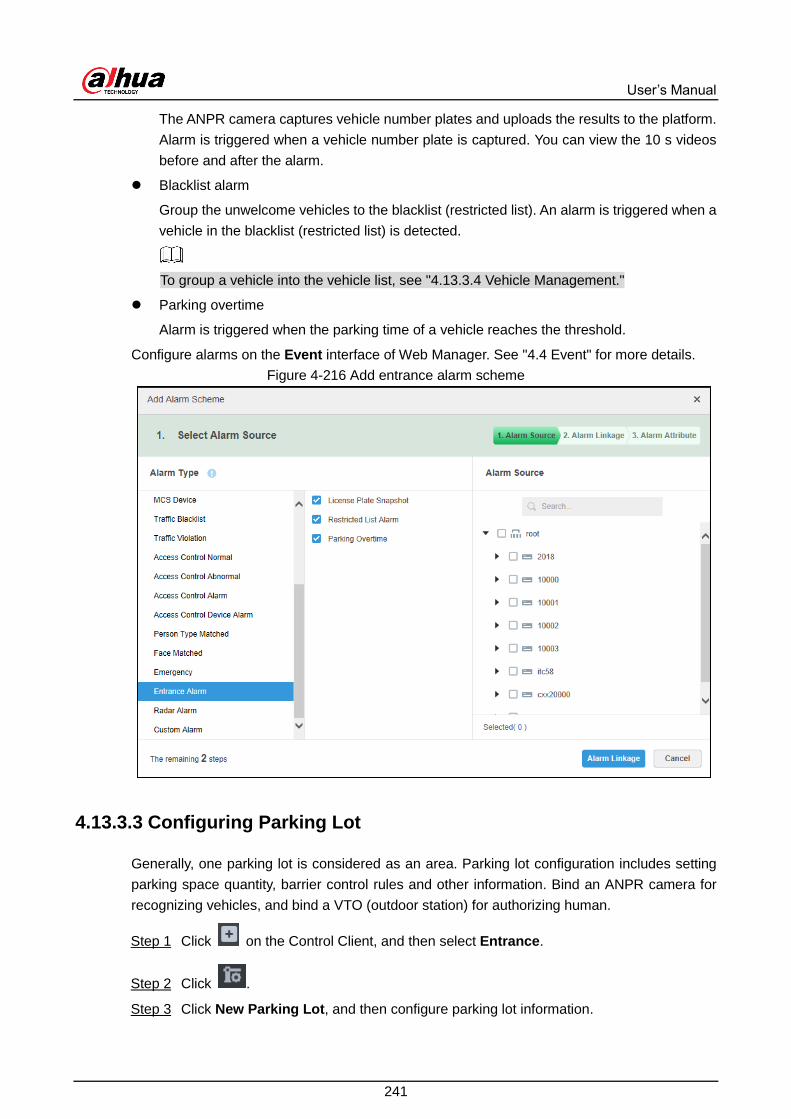
User’s Manual
241
The ANPR camera captures vehicle number plates and uploads the results to the platform.
Alarm is triggered when a vehicle number plate is captured. You can view the 10 s videos
before and after the alarm.
Blacklist alarm
Group the unwelcome vehicles to the blacklist (restricted list). An alarm is triggered when a
vehicle in the blacklist (restricted list) is detected.
To group a vehicle into the vehicle list, see "4.13.3.4 Vehicle Management."
Parking overtime
Alarm is triggered when the parking time of a vehicle reaches the threshold.
Configure alarms on the Event interface of Web Manager. See "4.4 Event" for more details.
Add entrance alarm scheme Figure 4-216
4.13.3.3 Configuring Parking Lot
Generally, one parking lot is considered as an area. Parking lot configuration includes setting
parking space quantity, barrier control rules and other information. Bind an ANPR camera for
recognizing vehicles, and bind a VTO (outdoor station) for authorizing human.
Click on the Control Client, and then select Entrance. Step 1
Click . Step 2
Click New Parking Lot, and then configure parking lot information. Step 3

User’s Manual
242
Add a parking lot Figure 4-217
Table 4-46 Parameters
Parameter Description
Parking lot
information
Name Parking lot name, used to recognize different areas.
Total parking
space Total available parking space of the area.
Available Available parking lot quantity when configuring area.
Dual Camera If one ANPR camera cannot meet your requirement of
recognition ratio, you can add a sub camera.
Dual Camera
Coordination
Time
The vehicles captured by the two cameras within the defined
period are considered as one vehicle. Set the time according
to your on-site distances and camera positions.
Vehicle No.
Overwrite
If an on-site vehicle has another entry record (exception case),
the calculation of parking space will go wrong. To avoid that,
you can enable this function, so that the system only keeps the
last entry record.
Alarm
Timeout
An alarm will occur when a vehicle has not left the parking lot
after the timeout threshold. You can configure parking
overtime alarm on the Web Manager. Alarm Time

User’s Manual
243
Parameter Description
Entry
Release
Time
Template
Select the time template which conforms to entry release. If
default template fails to meet the requirement, you can select
Manage Time Template to set custom time template.
Default templates include:
All-period template: 00:00 to 24:00 daily.
Weekday template: 00:00 to 24:00 Mon to Fri.
Weekend template: 00:00 to 24:00 Sat and Sun.
Zero residual
space
Release options when remaining space is zero.
1. No entry.
Any vehicle is not allowed to enter.
2. All
Any vehicle is allowed to enter.
3. Trusted list
Trusted vehicles include several vehicle types, such as no
group, general and VIP. Only the three types of vehicles above
are allowed to enter when remaining space is zero.
4. VIP
Only VIP vehicle is allowed to enter when remaining space is
zero.
Vehicle type should be set during vehicle management.
Auto Release
of Temporary
Vehicle
The vehicles not registered on DSS Pro are considered as
visitor vehicles. Confirm whether to unlock barrier automatically
when a visitor vehicle enters.
Exit
Release
Auto Release
of Temporary
Vehicle
The vehicles not registered on DSS Pro are considered as
visitor vehicles. Confirm whether to unlock barrier automatically
when a visitor vehicle exits.
Click Next Step. Step 4
Add the main ANPR camera. Step 5
Click Add, select a camera, and then click OK.
If there are multiple entrances and exits, add all the main cameras.

User’s Manual
244
Add a main camera Figure 4-218
Add a sub camera for the main camera, set the lane direction, bind VTO and the LED Step 6
screen.
1) Select the main camera from the device tree.
2) (Optional) Click Add, select a sub camera, and then click OK.
Sub camera is needed only when you configure the dual camera mode.
Add a sub camera Figure 4-219
3) Select the driving direction.
4) (Optional) Click Add, select the target VTO, and then click OK.
VTO is used for access control and opening barrier. Skip this step if you do not
need VTO.

User’s Manual
245
VTO information Figure 4-220
5) (Optional) To add a general LED screen, click Add next to Bind General LED
Display, select the screen, and then click OK.
Click Next Step. Step 7
To add a parking space LED screen, click Add LED, select the screen, and then click Step 8
OK.
Click Save and Exit. Step 9
4.13.3.4 Vehicle Management
Manage vehicle information including vehicle type, department, related personnel and barrier
control rule, which are used to confirm if the vehicle can enter.
Click on the Control Client, and then select Entrance. Step 1
Click . Step 2
Click Add to add vehicle information. Step 3

User’s Manual
246
Add vehicle information Figure 4-221
Table 4-47 Parameters
Parameter Description
Plate No. The plate number of added vehicle.
Vehicle Right
Select a group for the vehicle to give corresponding access permission.
Vehicles in the trusted list can get in and out of the parking lot. To
configure access permission for trusted vehicles when the parking
space reduces to zero, go to the Parking Lot Config interface.
Alarm is triggered when a restricted vehicle is detected. Restricted
vehicles are guarded away.
Vehicle Group
Group the vehicles. You can select No Group, Visitor Group, VIP Group
or General Vehicle. To configure access permission for VIP vehicles when
the parking space reduces to zero, go to the Parking Lot Config interface.
Vehicle Color Color of added vehicle. Set Not Recognized if vehicle color cannot be
recognized. Select Other for those beyond the selected range.
Vehicle Logo Main vehicle logos on the market.
Parking Lot The parking lot where the vehicle belongs (required).
Validity Time Validity period of added vehicle.
Expiration
New Vehicle If there are several vehicles, click the button to add more. One person can
add up to 5 vehicles.
Click Next. Step 4

User’s Manual
247
Personnel info Figure 4-222
Specify personnel information. Click Next Step. Step 5
Select ANPR devices, and then click Save and Exit. Step 6
● Trusted vehicle information will be sent to the ANPR camera. In case of
disconnection between the camera and the platform, the camera can still control
barrier according to the list.
● The restricted vehicle information will not be sent to the camera.
Authorization Figure 4-223
4.13.4 Entrance Applications
4.13.4.1 Overview
View the free parking ratio of current parking area; make statistics over real-time quantity and
on-site vehicle quantity, view quantity of entrance and exit vehicle within some period.

User’s Manual
248
Log in to the Control Client, and then select Entrance. Click on the Entrance interface to
view parking lot information.
Overview Figure 4-224
Table 4-48 Parameters
No. Description
1 Interface displays the information of selected area; see other items for included
content.
2 Display total parking spaces, occupied parking and free parking ratio of the selected
parking lot.
3
Select occupied parking space quantity of selected area, the result can be displayed
by line chart or bar chart. Hover over the image to display corresponding time and
occupied parking lot quantity.
4
Select vehicle access quantity of some period, supports day, week, month and year.
Select time after period is selected; the system displays vehicle access quantity of
selected period within the area. Blue means entered vehicle while orange means
exited vehicle. The result can be displayed by line chart or bar chart. Hover over the
image to display corresponding time and occupied parking space quantity.
User’s Manual
249
No. Description
5
Display following data.
Accumulated vehicle flow (hourly)
Vehicle flow within current hour (for example, it is 8:42, and then it will make
statistics about vehicle flow between 8:00 and 8:42).
Accumulated vehicle flow (Daily)
Vehicle flow of the day (Start statistics from 00:00)
Parking turnover
The bigger the parking turnover is, the shorter the vehicle stays in the parking lot,
and then parking space reuse ratio is higher. If it is a paid parking lot, then it will
make more money.
Parking Use Ratio
The bigger the parking use ratio is, the average time of vehicle parking is longer.
6 Automatically refresh overview information every 5 minutes. Click Refresh to sync
real-time data.
4.13.4.2 Number Plate Recognition
Log in to the Control Client, and then select Entrance. Click on the Entrance interface
to view live video and ANPR results.

User’s Manual
250
License plate recognition Figure 4-225
Table 4-49 Description
No. Description
1
Real-time image display area. Select window, and Double-click video channel bound
by ANPR in the device list, or drag the video channel bound by ANPR to window, and
the interface displays real-time image. Move the mouse on the image, interface
displays unlock button , click it to unlock barrier.
2 Device list. Display ANPR device and bound video channel.
3
Click the icon and it becomes , and the interface will no longer ANPR recognition
information. Click and the icon becomes , the interface will update real-time
ANPR recognition information.

User’s Manual
251
No. Description
4
, set height and width ratio of video window, it plays video by two
modes which are original scale and full screen.
, used to set image split mode, which includes 1 split, 4 splits and 9
splits, or click and customize split mode.
, switch video window to Full Screen mode. If you want to exit Full Screen,
you can also press ESC button or right-click to select Exit Full Screen.
5
Display latest 4 snapshots of LPR. More details as follows.
Double-click and display snapshot details, vehicle information, snapshot
panoramic picture and vehicle matting.
Click and view video of linked channel.
6
Display license plate snapshot and vehicle which need to be released manually. More
operation as follows.
Click and unlock barrier to release vehicle.
Click and view video of linked channel.
4.13.4.3 Vehicle Search
Search for entry and exit records, on-site vehicles and snapshot records.
4.13.4.3.1 Searching for Entry and Exit Records
Click on the Control Client, and then select Entrance. Step 1
Click on the Entrance interface. Step 2
Click the Vehicle Access tab. Step 3
Set search conditions, and then click Search. Step 4
Click More and you can search by vehicle owner, department and vehicle type etc.
Move the mouse pointer to the entry or exit picture, and then the system will
display a bigger picture.

User’s Manual
252
View bigger picture Figure 4-226
Double-click the record, and detailed information is displayed on the right. For the
dual camera mode, the snapshots from both the cameras are displayed; for the
single camera mode, there is only one snapshot. Double-click the snapshot in Info
to view bigger picture, drag the green box to the number plate to confirm the
number. Click Edit to modify vehicle information, click OK to save configuration.
Click Video to view linked video.

User’s Manual
253
Details (1) Figure 4-227

User’s Manual
254
Details (2) Figure 4-228
To export all searches, click Export All.
To set information display item, click and select items to be displayed.
Click Next to display the next record. Click Previous to go to the previous record.
4.13.4.3.2 Searching for On-site Vehicles
Click on the Control Client, and then select Entrance. Step 1
Click on the Entrance interface. Step 2
Click Vehicle in parking lot. Step 3
Set search condition, and then click Search. Step 4
Click More to search by vehicle owner, department and vehicle type.
If the vehicle is confirmed not in the parking lot, select the vehicle information, click
Force to Exit or .
To export all the information of on-site vehicles that can be searched, click Export
All.

User’s Manual
255
Click to set items to be displayed.
Click view mode ( ) or list mode ( ) to select different display mode.
4.13.4.3.3 Searching for Snapshot Records
Click on the Control Client, and then select Entrance. Step 1
Click on the Entrance interface. Step 2
Click Snapshot Record. Step 3
Set search condition, and then click Search. Step 4
Click More to search by vehicle owner, department and vehicle type.
Search results Figure 4-229
To export all the information of on-site vehicles that can be searched, click Export
All.
Click view mode ( ) or list mode ( ) and select different display modes.
Click to view video.

User’s Manual
256
POS 4.14
View POS live video and records.
Live view
View live POS video and the transaction details overlapped on the video.
Playback
Search for POS transaction records and play the recorded video. The POS video clip can
start 30 seconds earlier than the POS receipt printing.
4.14.1 Typical Topology
Typical topology Figure 4-230
Cameras record videos of each POS transaction.
NVRs are connected with cameras and POS machines, and store videos.
POS machines record transaction details and generate receipts.
The platform centrally manages NVRs and cameras, and provides live videos and POS
transaction video records.

User’s Manual
257
4.14.2 Business Flow
POS business flow Figure 4-231
4.14.3 Configuring POS Monitoring
4.14.3.1 Preparations
Make sure that the following preparations have been made:
Cameras, NVRs and POS machines are correctly deployed. For details, see the
corresponding user’s manuals.
Basic configurations of the platform have been finished. To configure, see "3 Basic
Configurations."
When adding an NVR on the Device interface of Web Manager, select Encoder for
device category.
At least one POS channel is connected to NVR.

User’s Manual
258
Add NVR Figure 4-232
On the Bind Resource interface, bind video channels to the POS channels.
Bind video channels to POS channels Figure 4-233
4.14.3.2 Setting POS End Sign
Set the end string of POS transaction receipt.

User’s Manual
259
Log in to the Web Manager, click , and then select System on the New Tab Step 1
interface.
Click the POS End tab. Step 2
Set the end line of POS receipt. Step 3
Set POS end sign Figure 4-234
Click Save. Step 4
4.14.4 POS Applications
View live and recorded videos of POS transactions.
4.14.4.1 POS Live View
View real-time POS transaction video and details.
This section introduces how to enable settings of live view and POS format. For more details
about live view, see "4.2 Live View."
Click on the Control Client, and then select Live View. Step 1

User’s Manual
260
Live view Figure 4-235
View POS video. Step 2
Select a POS-linked camera, double-click or drag it to window.
Double-click a POS device to display all the POS-linked cameras under it.

User’s Manual
261
POS video Figure 4-236
(Optional) Set POS information style. Step 3
1) Right-click and select Set POS Style on the live interface.
POS style setting Figure 4-237
2) Set Overlap Pattern, Font Size, Background Transparency and Font Color.

User’s Manual
262
3) Move the mouse pointer to POS information overlay area, press mouse left button
and move it to adjust POS information overlay position.
4) Click OK and save configuration.
4.14.4.2 POS Playback
Search POS receipt, view related video of receipt. You can search the video half an hour before
and half an hour after the time when POS receipt is printed, and you can start to play video 30s
before the time when POS receipt is printed.
This section mainly introduces how to replay related video of POS receipt.
Click on the Control Client, and then select Record Playback. Step 1
Click . Step 2
POS search Figure 4-238
Select channel from the device tree. Step 3
Enter Keyword, select Date and Time, click Search. Step 4

User’s Manual
263
Search result Figure 4-239
Double-click the POS information of related video that needs to be replayed. Step 5
POS video Figure 4-240
Flow Analysis 4.15
The system provides people counting report, stay people report and heatmap report.
Flow analysis report
Cameras report the analysis results to the platform, and then the platform can process and
show the corresponding reports.

User’s Manual
264
People stay report
The platform calculates and shows the numbers of people stay according to the analysis
data reported by cameras.
Heatmap
A heatmap shows people distribution in an area during a specific period in different colors,
so that you can see which section is more popular and which is less.
4.15.1 Typical Topology
Typical topology Figure 4-241
Cameras record videos and analyze people flow.
NVRs are connected with cameras. They analyze people flow and store videos.
The platform centrally manages all NVRs and cameras, receive analysis results from
cameras and shows the reports.
Flow analysis can be done by people counting camera or intelligent NVR.

User’s Manual
265
4.15.2 Business Flow
Flow analysis business flow Figure 4-242
4.15.3 Configuring Flow Analysis
4.15.3.1 Preparations
Make sure that the following preparations have been made:
Cameras and NVRs with people counting or heatmap function are correctly deployed, and
heatmap or people-counting rules have been configured and enabled on the devices. For
details, see the corresponding user’s manuals.
Basic configurations of the platform have been finished. To configure, see "3 Basic
Configurations."
When adding a camera or NVR on the Device interface of Web Manager, select
Encoder for device category.

User’s Manual
266
Add device Figure 4-243
On the Device interface, click of the camera channel, and then select Heat Map
Statistics or People Counting for Features.
Edit video channel features Figure 4-244

User’s Manual
267
4.15.3.2 Configuring Heatmap
Heatmap displays the distribution of moving objects in colors of different shades. It reflects the
temperature of regions by different colors. For example, red means the temperature is relatively
high, and blue means the temperature is relatively low. The configuration interface might vary
depending on the camera type. This section takes configuring Stereo Vision people counting
camera for example.
You can configure heatmap on the platform only when the camera is directly connected to the
platform. Otherwise, configure it on the camera or NVR.
Go to the Intelligent Analyse interface. Step 1
1) Log in to the Control Client, click , and then select Live View.
2) Right-click a camera, and then select Intelligent Analyse.
Go to intelligent analysis interface Figure 4-245
Click to select heatmap. Step 2
When the icon is displayed in the white frame, it means it is selected. If another smart
plan, which is conflicting with Heatmap, is selected already, click that smart plan icon to
deselect it and then click to select heatmap.
Smart plan Figure 4-246

User’s Manual
268
Heatmap Figure 4-247
Select the Enable check box to enable heatmap. Step 3
Modify rule name. Step 4
Configuring arming schedule and alarm linkage. Step 5
1) Click Config.

User’s Manual
269
Configure Figure 4-248
2) Click Arming schedule, select day and hours, and then set the start time and end
time.
The default arming schedule is 24 hours per day.
3) Click Alarm to set linkage actions.

User’s Manual
270
Alarm Figure 4-249
Table 4-50 Parameters
Parameter Description
Alarm output
Connect alarm output devices to the
alarm output interfaces. When an alarm
is triggered, the system will send the
alarm to the alarm output device.
Click Set next to Alarm
Latch and select an alarm
output channel.
Alarm latch The alarm output action will delay
stopping after the the alarm event ends.

User’s Manual
271
Parameter Description
Record
When an alarm happens, it will trigger
auto video recording immediately.
It requires the device to have recording
schedules already. See device manual
for detailed instruction.
Click Set next to Record to
select the recording
channel.
Record delay Video recording delays stopping for a
while after the alarm event ends.
Snapshot
The system will take snapshots
automatically when an alarm happens.
It requires the device to have snapshot
schedules already. See device manual
for detailed instruction.
Click Set next to Snapshot
to select the snapshot
channel.
Send email
The system will send an email to the
related mail address when an alarm
happens.
It requires the device to have email
configured already. See device manual
for detailed instruction.
None
4) Click Save.
Click Save. Step 6
4.15.3.3 Configuring People Counting
Configure people counting settings to analyze the number of people entry and exit.
You can configure people counting on the platform only when the camera is directly connected
to the platform. Otherwise, configure it on the camera or NVR.
Go into the Intelligent Analyse interface. Step 1
Click to select people counting. Step 2
When the icon is displayed in the white frame, the smart plan is selected. If another
smart plan, which is conflicting with people counting, is selected, click that smart plan
icon to deselect it and then click to select people counting.

User’s Manual
272
Smart plan Figure 4-250
Click Next. Step 3
The IVS Setting interface is displayed.

User’s Manual
273
People counting Figure 4-251
Click Add rule. Step 4
Enable rule and modify the name and type. Step 5
1) Enable rule. indicates rule is enabled.
2) Modify rule name.
3) Select rule type in the drop-down list of Rule type.
People Counting: System detects the number of people entry and exit in the
detection zone. When the number of entry/exit/stay exceeds the preset value,
system will trigger an alarm.
ManNumDetection: System detects people number and the duration of stay
inside the detection zone. When the people number or duration of stay
exceeds the preset value, system will trigger an alarm.
Select the default zone or line on the video and click Clear to delete it or Re-draw to Step 6
draw a new one.
People counting requires to draw a detection zone and a line while ManNumDetection
requires only a detection zone.

User’s Manual
274
When drawing the line from left to right, the direction is A to B, and then people flow
from A to B is entry number and B to A is exit number. When drawing the line from right
to left, the direction is B to A, and then people flow from B to A is entry number and A to
B is exit number.
Set parameters, arming schedule and alarm linkage. Step 7
1) Click Config and set parameters.
Set parameters (People counting) Figure 4-252

User’s Manual
275
Set parameters ( ManNumDetection) Figure 4-253
Table 4-51 Parameters
Parameter Description
Min Height When the target height is between the minimum height and maximum
height, system will trigger the statistics rule. Max Height
Man Num Alarm
Enable When the people number in the zone reaches, exceeds or is smaller
than the preset value, system will trigger an alarm. Man Num
Threshold
Detect Mode
Stay Detect
Enable
When the people stay time in the zone is exceeds the preset value,
system will trigger an alarm.

User’s Manual
276
Parameter Description
Stay Min Duration
Enter No. When the entry number exceeds the preset value, system will trigger an
alarm.
Exit No. When the exit number exceeds the preset value, system will trigger an
alarm.
Remaining No. When the remaining people number exceeds the preset value, system
will trigger an alarm.
Sensitivity It is recommended to keep the default value.
2) Click Arming schedule, select day and hours and then set the start time and end
time.
The default arming schedule is 24 hours per day.

User’s Manual
277
Arming schedule Figure 4-254
3) Click Alarm to set linkage actions.

User’s Manual
278
Alarm Figure 4-255
Table 4-52 Parameters
Parameter Description
Alarm output
Connect alarm output devices to the
alarm output interfaces. When an alarm
is triggered, the system will send the
alarm to the alarm output device.
Click Set next to Alarm
Latch and select an alarm
output channel.
Alarm latch The alarm output action will delay
stopping after the alarm event ends.

User’s Manual
279
Parameter Description
Record
When an alarm happens, it will trigger
auto video recording immediately.
It requires the device to have recording
schedules already. See device manual
for detailed instruction.
Click Set next to Record to
select the recording
channel.
Record delay Video recording delays stopping for a
while after the alarm event ends.
Snapshot
The system will take snapshots
automatically when an alarm happens.
It requires the device to have snapshot
schedules already.See device manual for
detailed instruction.
Click Set next to Snapshot
to select the snapshot
channel.
Send email
The system will send an email to the
related mail address when an alarm
happens.
It requires the device to have email
configured already. See device manual
for detailed instruction.
4) Click Save.
Click Save. Step 8
4.15.4 Flow Analysis Applications
4.15.4.1 Heatmap
Heatmap displays the distribution of moving objects in colors of different shades. It reflects the
temperature of regions by different colors. For example, red means the temperature is relatively
high, and blue means the temperature is relatively low.
Click on the homepage, and then click Flow Analysis. Step 1

User’s Manual
280
Heatmap Figure 4-256
Click the tab on the flow analysis interface. Step 2
Select a channel, set time, and then click Search. Step 3
The device sends heatmap data to platform in real time. Heatmap data of a channel
can be searched once the channel is added to the platform. You can only search within
a week at one time.
Heatmap interface Figure 4-257

User’s Manual
281
Click Export at the upper-right corner to export heat map in .bmp format. Step 4
4.15.4.2 People Counting Report
View reports of the numbers of people entry and exit in a specific time period. A day report also
includes the number of people who has not yet left the target area in the defined period.
The statistics can be generated by camera or by people-counting rule.
4.15.4.2.1 Generating Report by Camera
Select the camera of interest to view the people-counting statistics. For example, if your store
has one door, to view the total number of people entry and exit from your store, select the
people-counting camera for generating the report.
On the Flow Analysis interface, click Step 1
People counting interface Figure 4-258
Click the Resources tab. Step 2
Select a people-counting channel, set report type and search time, and then click Step 3
Search. The report is displayed.
To switch to line chart or list, click the corresponding tabs on .

User’s Manual
282
Stay People report (number of people still in a place) is only available for the daily
report.
People-counting report by camera Figure 4-259
To save the report, you can click Export at the upper-right corner. The report is Step 4
exported in the .pdf format.
4.15.4.2.2 Generating Report by People-Counting Tripwire
To view the people-counting report of an area, if the total statistics result must be generated
from multiple people-counting tripwires, you can select all the relevant tripwires for generating
the report.
On the Flow Analysis interface, click Step 1
Click the Rule tab. Step 2

User’s Manual
283
Rule interface Figure 4-260
Add rules. Step 3
1) Click Add Rule.

User’s Manual
284
Add rule Figure 4-261
2) Enter rule name.
3) Click Add, select a channel and one or more rules as needed.
If your store has two doors each equipped with a people-counting camera, you
need to add both the two cameras, and select the corresponding rules from them.
4) Click OK.
Click the rule name to select a rule, set the search period (day, week, month, or year), Step 4
set the date from the calendar, and then click Search.
The report is generated. See Figure 4-262.
To switch to line chart or list, click the corresponding tabs on .
Stay People report (number of people still in a place) is only available for the daily
report.

User’s Manual
285
People-counting report by rule Figure 4-262
To save the report, you can click Export at the upper-right corner. The report is Step 5
exported in the .pdf format.
4.15.4.3 Dwell Time Report
With the people-counting cameras deployed at entrances and exits, the system can calculate
the number of people that have stayed in an area for a specific period. You can view the daily,
weekly and monthly report on the Control Client.
For example, to view the daily report of the number of people that stayed in an area for 5
seconds, see the following procedure.
On the Flow Analysis interface, click . Step 1

User’s Manual
286
Dwell time report Figure 4-263
Select cameras, select Day in the Day drop-down list, set a date on the calendar, and Step 2
then select Dwell Time 5s in the corresponding drop-down list. Click Search.
The report is displayed.
(Optional) To export the report, click Export. Step 3
Human Face Recognition 4.16
Configure face recognition settings on the device and the platform before you can view face
recognition results on the platform.
4.16.1 Typical Topology
The face recognition feature is available on select models of NVR, IVSS and FR camera.

User’s Manual
287
Face recognition by NVR/IVSS
Typical topology (NVR/IVSS) Figure 4-264
Cameras record videos.
NVR/IVSS is used for face recognition and storage.
DSS Pro centrally manages cameras, NVRs, and face database, and provides live
view and face search.
Face recognition by camera
Typical topology (camera) Figure 4-265
Cameras collect face videos, detect and recognize faces.
DSS Pro centrally manages cameras, NVRs, and face database, and provides live
view and face search.

User’s Manual
288
4.16.2 Business Flow
face recognition business flow Figure 4-266
4.16.3 Configuring Face Recognition
4.16.3.1 Preparations
Make sure that the following preparations have been made:
Face recognition devices are correctly deployed. For details, see the corresponding user’s
manuals.
Basic configurations of the platform have been finished. To configure, see "3 Basic
Configurations."
When adding face recognition devices on the Device interface of Web Manager,
select Encoder for device category.

User’s Manual
289
Add device Figure 4-267
After adding a face recognition NVR or IVSS, set face recognition features for the
corresponding channels.
On the Device interface, click of the NVR or IVSS, and then select Face
Recognition for Features.
Edit features (1) Figure 4-268

User’s Manual
290
On the Device interface, click of the face recognition camera or face detection
camera, and then select Face Recognition or Face Detection for Features.
The platform can automatically obtain the features of the face recognition camera.
Edit features (2) Figure 4-269
Face snapshots are stored in the Face/Alarm and Other Pictures disk. On the
Storage Config interface, configure at least one local disk for picture storage.
Otherwise, the platform cannot display snapshots.
Set face snapshot storage disk Figure 4-270
4.16.3.2 Configuring Face Database
Configure face database which contains people face information, so the system can compare
the detected face with those in the database to determine who it is and whether to let go. The
platform supports up to 50 face databases.

User’s Manual
291
4.16.3.2.1 Creating Face Database
Click on the Web Manager, and then select Face Database. Step 1
Click Add. Step 2
Add a face database Figure 4-271
Enter database name, select color, and then click OK. Step 3
Other Operations
Search database
Filter the database by face database type or keyword.
Add face database
Click to add face information.
Modify database
Click to modify database name and database description.
Delete database
Click .
4.16.3.2.2 Configuring Person Type
Up to 16 types are allowed. Face alarms can be configured and triggered by people type.
Click the face database which needs to be added with person. Step 1
Click Person Type Config. Step 2

User’s Manual
292
Set person types Figure 4-272
Click Add and enter type name in the column of Person Type. Step 3
Support adding up to 16 person types.
Click to disable the window. Step 4
4.16.3.2.3 Adding Face database Information
Add people information one by one or in batches. Face recognition is based on the matching
between detected face and faces in the database. The platform supports up to 300 thousand
faces.
Adding Faces One by One
Enter people information interface in two ways: Step 1
Click the database which needs to be added with people on the Face database
Manage interface.

User’s Manual
293
Add a face database Figure 4-273
Click on the person card.
Set person details Figure 4-274
Enter person information. Step 2
Click profile photo and upload a face picture. Step 3
Click OK. Step 4

User’s Manual
294
Adding Faces in Batches
Prepare face pictures in advance if you want to import in batches, and compress it into zip, rar
or 7z files. The ID cannot be repeated. Currently batch import supports max 10,000 pictures at
one time.
Zip file Figure 4-275
Click the database to add people on the interface of Face database Manage. Step 1
Click Import. Step 2
Import faces in batches (1) Figure 4-276
Click Import File and upload compressed package according to prompt. Step 3
Operations
Query person
Enter key words into the query text box, and then press Enter or click .
Delete person
Click on person interface and then you can delete person individually.
Select person, and then click Delete to delete person in batches.
4.16.3.3 Arming Face Recognition Channels
Enable real-time face recognition. To arm specific people, you can arm the face database of the
people. The armed face database is sent to the devices.
Click and select Face Database on the New Tab interface. Step 1
Click Face Device Config on the left of navigation bar. Step 2
Click to start arming. Step 3

User’s Manual
295
Select a channel Figure 4-277
Select the target channels, and then set similarity. Step 4
Click OK. Step 5
If the arming is prompted failed, appears on the database card. Click it to
check detailed reason.
To re-arm, click , modify people information, and then click Reissue.
Modify people information Figure 4-278
Operations
Modify arm
Arm has been implemented; click and it can modify related device and similarity value
on the arm interface.
Disarm

User’s Manual
296
Click on the interface of Arm Manage to disarm.
4.16.4 Face Recognition Applications
View live or recorded face recognition videos and search for face records. You can search for
records by face attributes, or by simply uploading a face image.
4.16.4.1 Real-Time Face Recognition
View face recognition in real time.
Click on the Control Client, and then select Face Recognition. Step 1
Click . Step 2
Live video Figure 4-279
Table 4-53 Description
No. Name Description
1 Device Tree Display face detection and face recognition device
information.

User’s Manual
297
No. Name Description
2 Pause Refresh/Start
Refresh
: When this icon is on the interface, the
snapshot display pane does not refresh human
face snapshot image. Click the icon, system
displays real-time face image.
: When this icon is on the interface, the
snapshot display pane refreshes human face
snapshot image. Click the icon, system refreshes
human face snapshot image.
3 Face Record Display the face snapshots of the opened video
channels.
4 Monitor Window
Display channel preview video. In multiple-window
display mode, double-click the window to switch to
1-window display mode. Double-click the window
again to restore original mode.
5
Image Display
Rate
There are two modes: full screen, and original scale.
The full screen refers to one window at the full screen.
Window Split
Switch
Display switched window amount. System supports
customized settings.
Full Screen
Display The system displays window at full screen.
6 Face Recognition Records Display recognition records of the opened video
channels.
Enable live view. Step 3
Select a monitor window, and then double-click a channel or record file.
Drag the channel or the video file to the monitor window.

User’s Manual
298
Enable live view Figure 4-280
Face monitoring. Step 4
Double-click a snapshot image to view details
Right-click the snapshot, and then you can register faces, search for faces, query
tracks, and export snapshots.
Right-click the recognition record, and then you can query recognition records and
face tracks and export snapshots.
4.16.4.2 Face Search
With the human face recognition function, you can search the face databases or snapshot
records for face pictures of interest by setting person features such as age and gender or
uploading a face picture. The face database contains all registered faces; the snapshot records
are all the faces captured by the cameras.
Searching by image is only available with IVSS and NVR.
Click on the Control Client, and then select Face Recognition. Step 1
Click . Step 2
Set search conditions. Step 3
You can search the face database (by selecting the Face database option under
Search in) or snapshot records (by selecting the Record option under Search in).
You can upload a face picture to match or set target features to narrow down the
conditions.

User’s Manual
299
When you search by Record or Picture, you can select Start from Earliest Time
or Start from Current Time from the Sequence drop-down list to set time
sequence for the results. Up to 1000 results can be displayed.
Click Search. Step 4
Search result Figure 4-281
When searching a face database, the results are displayed in list; when searching the
snapshot records, you can choose to display the results in list or view face tracks on
the map. To introduce search results, now we take searching snapshot records as an
example.
When searching the snapshot records by uploading a face picture, the search
progress is displayed at the top-right corner. To end searching, click .
It is not available to search for face tracks on map when you are searching the
face database.
The face track function is only available when you have linked the relevant
cameras onto the map.
Click List, and then the search results are displayed in list.

User’s Manual
300
Search results in list Figure 4-282
Table 4-54 Functions description
Operation Description
Download
Record Click to save rar file to the specified path. The .rar file contains the
human face snapshot images and snapshot panorama images.
Playback record Click to playback the 15-seconds video record before and after the
snapshot.
Add person
Add the snapshot person to the database.
1. Click .
2. Set person information and then click OK.
Search record
You can upload a face image to search for the target face record.
1. Click , and then system goes to human face search interface with
the snapshot image.
2. Click Search. The search results are displayed.
Click Track, the face track is displayed on the map.

User’s Manual
301
Face track on map Figure 4-283
You can perform the following operations on the map.
Double-click the device on the map, and the detailed snapshot records are listed
on the left.

User’s Manual
302
View detailed snapshot records Figure 4-284
Click to play the moving track. Click to stop. Click to play again.
Click to play back video.
The video is uploaded by device. Playback will fail if the video is not stored on the
device.
Double-click a piece of record on the left to view the details.
To export the track picture, click Export Screenshot, and then follow the onscreen
instruction to save the picture locally.
4.16.4.3 Face Recognition Record Search
Search for recognized faces by time, device, person type, name, gender, age and certificate
number. You can view search results in list or check face tracks on the map.
On the Face Recognition interface, click . Step 1

User’s Manual
303
Recognition record search Figure 4-285
Set search criteria. Step 2
You can search by time, device, person type, name, gender, age and certificate
number.
Click Search. Step 3
Support viewing records in list or checking face tracks on the map.
To achieve the face track function, make sure that you have linked face cameras onto
the map.
Click List, and then the records are displayed in list. Double-click a search result,
and the detailed information is displayed. There is no image on the left if you do
not upload image when setting search criteria.

User’s Manual
304
Records in list Figure 4-286
Record details Figure 4-287
Table 4-55 Functions description
Operation Description
Download
Record Click to download video.

User’s Manual
305
Operation Description
Playback record Click to play back the 10-seconds video records before and after the
snapshot.
Search record Click to search for records.
Click Track. The face track is displayed on the map. For more instruction about
face track operation, see "4.16.4.2 Face Search."
4.16.4.4 Face Reports
View face reports that show face statics involving age, gender, and other properties.
Click on the Control Client, and then select Face Recognition. Step 1
On the Face Recognition interface, click . Step 2
Statistics report search Figure 4-288
Set search criteria. Step 3
Set video channel, report type and time.
Click Search. Step 4

User’s Manual
306
Reports Figure 4-289
Results are displayed by line chart by default.
Click to display by pie chart.
Click to display by list.
Click Export to export statistics result in .xlsx format.
Target Detection 4.17
View and search for metadata of people, vehicle and non-motor vehicle.

User’s Manual
307
4.17.1 Typical Topology
Typical topology Figure 4-290
General cameras record videos.
Video metadata cameras such as panoramic + PTZ camera record videos and analyze
people, vehicles and non-motor vehicles.
NVRs manage cameras and analyze people, vehicles and non-motor vehicles.
The platform centrally manages NVRs and cameras, receive analysis results from
cameras and shows the reports.
Target detection can be done by video metadata cameras or intelligent NVRs.
4.17.2 Business Flow
Target detection business flow Figure 4-291

User’s Manual
308
4.17.3 Target Detection Applications
4.17.3.1 Preparations
Make sure that the following preparations have been made:
Cameras and NVRs are correctly deployed, and video metadata is enabled on them. For
details, see the corresponding user’s manuals.
Basic configurations of the platform have been finished. To configure, see "3 Basic
Configurations."
When adding a camera or NVR on the Device interface of Web Manager, select
Encoder for device category.
Add device Figure 4-292
On the Device interface, click or of the camera or NVR, and then select Target
Detection for Features.

User’s Manual
309
Edit video channel features Figure 4-293
4.17.3.2 Viewing Real-time Detection
To view the real-time snapshots captured by the cameras, including information about human,
vehicles, and non-motor vehicles:
Log in to the Control Client, click , and then select Object Detection. Step 1
Click . Step 2

User’s Manual
310
The real-time detection interface is displayed.
Real-time detection interface Figure 4-294
Table 4-56 Description
No. Name Description
1 Device Tree Displays device information.
2 Pause Refresh/Start
Refresh
If the interface displays , the snapshot display
area does not refresh snapshots. Click this icon to
refresh face snapshots in real time.
If the interface displays , the snapshot display
area refreshes face snapshots. Click this icon to
stop refreshing snapshots.
3 Monitoring window
Displays the channel live video. In the multi-window
display mode, double-click a window to switch to
single window display. Another double-clicking returns
to the original multi-window display mode.
4
Picture display
ratio
Supports Full Screen and Original Scale modes. The
Full Screen mode refers to the single window display
in full screen.
Number of
windows
Supports switching the number of display windows,
and you can customize the numbers.
5
The button that allows for
jumping to the Report
Statistics interface.
Click this icon to jump to the Report Statistics
interface.
6 Snapshot display area Displays the captured face snapshots.
Turn on live view. Step 3

User’s Manual
311
Select the monitoring window (a white frame means the window has been
selected), and double-click any channel or video recording to enable real-time
monitoring.
Drag the channel or video recording to the monitoring window.
Turn on the live view display. The client displays snapshots in real time. Step 4
Live view display Figure 4-295
Double-click the snapshot to view details. Step 5
Human snapshots display body cutout, types of tops, colors of tops, types of
bottoms, colors of bottoms, carrying bags or not, wearing caps or not, and the
gender. If faces are recorded, the system displays face snapshots, age, facial
expression, wearing glasses or face masks. You can zoom in any part of the
human body image, go to the search interface, and view the recordings. You can
quickly go to search by image interface or register the faces to the database.
Vehicle snapshots display the panoramic view of vehicles, vehicle type, vehicle
color, license plate color, and logo. You can view license plate snapshots, play
linked videos and zoom in specified parts of the vehicle image.
Click and save .rar files in the specified path.
Click to play back the video recordings timed before and after the
snapshot.
Non-motor vehicle snapshots display the panoramic view, vehicle type, vehicle
color, and the number of people involved.

User’s Manual
312
4.17.3.3 Searching for Target Detection Records
Log in to the Control Client, click , and then select Object Detection. Step 1
Click . Step 2
Set search conditions and click Search. Step 3
You can search by human, vehicle and non-motor vehicle. If you use IVSS or smart
MVR for target detection, you can upload a picture to search for similar targets.
Search results Figure 4-296
Actions available. Step 4
Double-click the snapshot to view details.

User’s Manual
313
Snapshot details Figure 4-297
● To download video, click .
● To play video, click .
● To export searches, select the records, and then click Export Selected.
4.17.3.4 Reports
Click on the Control Client, and then select Object Recognition. Step 1
Click . Step 2
On the upper-right corner, select the period type and date. The report shows the people, Step 3
motor-vehicle and non-motor vehicle data during the defined period.

User’s Manual
314
Report interface Figure 4-298
Thermal 4.18
View live or recorded videos of thermal cameras for temperature monitoring. The thermal
cameras can be connected to the platform directly or through NVR, IVSS or EVS.
Real-time temperature measurement
After adding devices on the Web Manager, log in to the Control Client. On the Thermal
interface, drag a thermal camera from the device tree to the live view window, and then
click anywhere on the video to view the temperature of the point.
Thermal analysis
After adding thermal devices on the Web Manager, you can view the thermal view on the
Control Client. You can use the thermal analysis tools to generate temperature information
and temperature ratio on the thermal view. You can also select one or more sections on the
thermal view, and use the tools to calculate maximum temperature, minimum temperature,
average temperature and temperature difference.

User’s Manual
315
4.18.1 Typical Topology
Typical topology Figure 4-299
Thermal devices record videos, analyze temperature, and upload thermal information to
the platform.
The platform centrally manages all devices, receive and analyze thermal data, and
provides reports.
4.18.2 Business Flow
Thermal business flow Figure 4-300

User’s Manual
316
4.18.3 Thermal Applications
4.18.3.1 Preparations
Make sure that the following preparations have been made:
Thermal devices are correctly deployed. For details, see the corresponding user’s
manuals.
Basic configurations of the platform have been finished. To configure, see "3 Basic
Configurations."
When adding thermal devices on the Device interface of Web Manager, select
Encoder for device category.
Add device Figure 4-301
After the device is added, click , and select IR Temperature Measurement from
the Features drop-down box.

User’s Manual
317
Set device features Figure 4-302
4.18.3.2 Real-time Temperature Measurement
Click on the Control Client, and then select Thermal. Step 1

User’s Manual
318
Thermal interface Figure 4-303
Table 4-57 Description
No. Module
name Description
1 Device Tree
If in Local Config > Basic Setting, you select Show device
node, the Device Tree shows the device and the channels under
it. If the selection is undone, channels of all devices are
displayed.
Supports searching and querying in by
organization name, device name, or channel name.
2 Preview
You can preview channel videos. Drag the channel to the window or
select the window and double-click a channel to open videos of
corresponding channels.
3 Heatmap
The heatmap is formed by capturing the temperature value of each
pixel point on the thermal image and can be analyzed on the client.
See "4.18.3.3 Heatmap Analysis" for specific steps.
4 PTZ Control To control the PTZ or speed dome, rotate the device to zoom in/out,
change focus and adjust aperture.
Drag a thermal camera from the device tree to a window to play the live video, and then Step 2
click anywhere on the video to view the temperature of this point.

User’s Manual
319
Real-time temperature measurement Figure 4-304
Hover over the video to display the shortcut menu.
Menu Figure 4-305
Table 4-58 Description
No. Icon name Description
1 Real-time
Tagging
If in Local Config > Basic Setting, you select Silent Real-time
Tagging, the Tagging dialog box does not display at the time of
real-time tagging.
If Silent Real-time Tagging is not selected, you can edit the tag
name.
2 Audio Turn on or off audio.
3 Intercom Turn on or off audio talks.

User’s Manual
320
No. Icon name Description
4 Local Record
Click this icon and the system begins recording a local video.
Clicking this icon again stops recording and the recorded video file
is stored locally.
5 Snapshot Click this icon and the system takes snapshots automatically.
6 Off Click this icon to turn off this video channel.
4.18.3.3 Heatmap Analysis
Heatmap of devices can be obtained on the client. The heatmap analysis tools available on the
client can generate temperature values and the ratio of each temperature value on the heatmap.
You can also select one or more monitored regions on the heatmap. The tools can calculate the
max temperature, min temperature, and average temperature within a region, and also
temperature differences.
Heatmap and analysis tool interface Figure 4-306
Table 4-59 Parameters
No. Module
name Description
1 Query
heatmap You can obtain heatmap manually.
2 Draw a region
You can draw a region on the heatmap to measure the temperature.
The region can be a point, a rectangle, a circle, a line segment, or a
polygon. See 4.18.3.3.2Regional Temperature for specific steps.
3 Mode Not supported for now.

User’s Manual
321
No. Module
name Description
4 File
processing
You can import heatmap processing files (.dtp) to the client for
analysis, or generate heatmap analysis reports.
5 Temperature
display
Generates a bar reflecting the color changes corresponding to
different temperature values, based on the rendering plan selected
in the heatmap. The data at the two ends defines the temperature
range in the heatmap.
Temperature-color correlation: When the mouse is placed at a
color spot, the temperature of the color spot is displayed.
Enhanced temperature comparison display: After inputting
temperature values in the boxes at the two ends of the bar, the
heatmap only displays the colors of the regions within this
temperature range. Regions with temperatures below the
preset min value are displayed in the leftmost color on the bar;
regions with temperatures above the preset max value are
displayed in the rightmost color on the bar.

User’s Manual
322
No. Module
name Description
6 Rendering
Plan
Click to color the infrared image. 14 color plans are available.
White-heat: In gray-scale images, the parts with higher
temperature are brighter.
Black: In gray-scale images, the parts with lower temperature
are brighter.
Purple-yellow: Colors mostly fall within the purple-red-yellow
range. The parts with lower temperatures are purpler, and
higher temperatures more yellow.
Rainbow: Colors mostly fall within the blue-green-red-yellow
range. The parts with lower temperatures are bluer, and higher
temperatures more yellow.
Red-yellow: Colors mostly fall within the red-yellow range. The
parts with lower temperatures are redder, and higher
temperatures more yellow.
Blue-yellow: Colors mostly fall within the blue-purple-red-yellow
range. The parts with lower temperatures are bluer, and higher
temperatures more yellow.
Iron red: Similar colorway to the Blue-yellow plan but less
bright.
Amber: Mainly dark brown. The parts with higher temperatures
are brighter.
Jade: Colors mostly fall within the purple-red-yellow-green-blue
range. The parts with lower temperatures are purpler, and
higher temperatures bluer.
Sunset: Colors mostly fall within the blue-red-yellow range. The
parts with lower temperatures are bluer, and higher
temperatures more yellow.
Red and Blue: In colored images, objects with higher
temperatures are displayed in red, and those with lower
temperatures are displayed in blue. Usually used to give
warnings.
Oil painting: Colors mostly fall within the
purple-blue-green-yellow-red range. The parts with lower
temperatures are purpler, and higher temperatures redder.
Pomegranate: Mainly burgundy. The parts with higher
temperatures are brighter.
Emerald: Mainly azure green. The parts with higher
temperatures are brighter.
The default setting is White-heat.

User’s Manual
323
No. Module
name Description
7 Temperature
Filter
Filters the temperatures on the heatmap. You can set up a
temperature range. The heatmap within this temperature range is
displayed in other colors. See "4.18.3.3.3 Temperature Filter" for
specific steps.
8
Select
isothermal
region
The isothermal lines are mainly used to highlight some parts of the
image. The temperature range is around a median temperature,
between an upper limit and a lower limit. Those above the lower limit
appear in bright colors, and those below the lower limit appear in
black & white. See "4.18.3.3.3 Temperature Filter" for specific steps.
9
Reset
isothermal
region
Click to delete the isothermal regions already drawn.
10
Regional
Temperature
Data
On the heatmap, select a region (except for points). The table
displays the max temperature, min temperature, and average
temperature of the selected region. See "4.18.3.3.2 Regional
Temperature" for specific steps.
11 Temperature
ratio
It displays the ratios of various temperature values on the heatmap
intuitively.
12 Temperature
Difference
The differences of max temperature, min temperature, and average
temperature within the same region or across different regions can
be calculated. See "4.18.3.3.2 Regional Temperature" for specific
steps.
4.18.3.3.2 Regional Temperature
Draw a detection region on the heatmap and you can see the max temperature, min
temperature, and average temperature in this region on the client. After adding multiple regions
on the heatmap, you can compare the temperature differences across multiple regions.
Drawing a Region and Measuring the Temperature
In the region drawing section, select a shape and draw on the heatmap. Step 1
The Regional Temperature Data section is automatically updated with the max
temperature, min temperature, and average temperature of the region.
Place the mouse near the edge of the region. When the mouse changes into ,
moving the mouse changes the size of the regular region.
Place the mouse within the region. When the mouse changes into , moving
the mouse changes the position of the regular region.
Delete a single regular region: Select a region in Regional Temperature Data
section, or a regular region on the heatmap. Right-click and select Delete to delete
the corresponding regular region.

User’s Manual
324
Delete all regular regions: In Regional Temperature Data section, click , or
select any regular region, right-click and select Delete All to delete all regular
regions.
Draw a region Figure 4-307
Regional temperature data Figure 4-308
Click any temperature data. Step 2
Temperature ratios of the region can be displayed in the gradient graph on the side.
Place the mouse on the graph and the temperature range and its ratio on the heatmap
can be displayed.

User’s Manual
325
Temperture ratio Figure 4-309
Temperature Difference
Support up to 100 temperature difference calculation rules.
Click in the Temperature Difference section to add rules for calculating the Step 1
temperature difference.
Click on the right side of to delete all temperature difference calculation
rules.
Click on the right side of each difference to delete the corresponding
temperature difference calculation rule.
Temperature difference interface Figure 4-310
Click the drop-down box on the left side and select regions that have been set up, such Step 2
as Li1, El1.
Click the drop-down box on the right side and select the temperature to be compared Step 3
with, such as the Max Temp., Min Temp., or Average Temp.
The system automatically calculates the temperature difference.

User’s Manual
326
Temperature difference Figure 4-311
4.18.3.3.3 Temperature Filter
Temperature Filter
To set up temperature limits, and select and highlight regions that fall within the limits on the
heatmap.
Click to enable temperature filter. Step 1
Temperature filter Figure 4-312
Select the temperature filtering criteria. Available options include Above, Below, or Step 2
Between.
Input the temperature limits and set up colors. Step 3
The client displays the temperature filtering results.
When Above or Below is selected as the filtering criteria, just fill in one value as the
limit.
When Between is selected, fill in both the upper limit and the lower limit.

User’s Manual
327
Temperature filtering results Figure 4-313
Select isothermal region
The isothermal region is mainly used to highlight some objects in the image. With the drawn
isothermal region as the benchmark, regions with higher temperatures display in bright colors,
and those with lower temperatures display in dark colors.
Click . Step 1
Draw regions on the heatmap. Step 2
The color bar below the heatmap only displays the temperatures within the region.
Place the mouse near the edge of the region. When the mouse changes into ,
dragging the mouse changes the region size.
Only one isothermal region is allowed on the heatmap.
Click to delete the isothermal regions already drawn.

User’s Manual
328
Isothermal region Figure 4-314
4.18.3.3.4 File processing
Import Local Heatmap
Click . Step 1
The heatmap import interface is displayed.
The system supports .dtp heatmap file only.
Select a heatmap file and follow the instructions on the interface to import it into the Step 2
system.
Import heatmap files to the client and analyze them.
Generate Heatmap Analysis Result
You can generate heatmap analysis reports in .pdf.
Click . Step 1

User’s Manual
329
Export analysis results Figure 4-315
Click Export as PDF and follow the instructions on the interface to save the exported Step 2
file.
Save Heatmap
Click . Step 1
Export analysis results Figure 4-316
Save heatmap. Step 2
Click Save to save the rules already set up on the heatmap.
Click Save as…, select the save path in the popup interface, and click Save to
save the heatmap to a local disk.
Personnel Management 4.19
Configure personnel information for the applications of access control, vehicle control, video
intercom and attendance management. Personnel information contains card number, password,
face picture, and more.

User’s Manual
330
Personnel Management Figure 4-317
4.19.1 Configuring Personnel Information
4.19.1.1 Adding Departments
Adding department is to manage personnel in the added departments.
Click on the Control Client, and then select Personnel Management. Step 1
Select a node from the department list on the left side, and then click . Step 2

User’s Manual
331
Add a department Figure 4-318
Enter department name and click OK. Step 3
Added department Figure 4-319
To delete a department, select it, and then click . You cannot delete a
department with personnel.
To rename a department, select it, and then click .
4.19.1.2 Adding Personnel
Add personnel and authorize them to unlock doors. When adding personnel, system uploads
the collected personnel information to the server for proper protection.
Person ID shall be the same on the platform and access control devices; otherwise person

User’s Manual
332
data could be wrong.
To collect fingerprints or card No., connect a fingerprint collector or card reader first.
IR face feature code is obtained from the access control device when editing person
information.
4.19.1.2.1 Adding a Person
Log in to the Control Client, click , and then select Personnel Management. Step 1
Click Add. Step 2
Add a person Figure 4-320
Click the Basic Info tab to configure person information. Step 3
1) Hover over the profile, and then click Upload Picture to select a picture or click
Snapshot to take a photo.
Click on the Snapshot interface, and then you can select camera, pix format,
resolution, and image quality. This is only effective with the current client.
2) Fill in personnel information as necessary. ID is required and must be unique, and
others are optional.
If the personnel information is already on the device, you can enter the ID number,
and then click Extract to obtain the information.
Click the Detail tab, and then set person details as required. Step 4
Click the Authentication tab, and then set validity period and access control Step 5
information.

User’s Manual
333
Authentication Figure 4-321
Table 4-60 Authentication parameters
Parameter Description
Term of
Validity
Validity Time Effective time of the access control permission.
Expiration Expiration time of the access control permission.
Access
Control
Property
Set person types.
If the person has the permission of First Card Unlock, you
need to select General in the Property drop-down list.
Device
Manager
Personnel include common people and system managers. A
device manager has the device operation permission. This
function is only effective when the person information is
applied to the second-generation devices.

User’s Manual
334
Parameter Description
Resident
Information
Room No.
Room No. is the number of the apartment in which this
person lives. The room No. is displayed in the access
records and video intercom operation records. Access
permission of the corresponding VTO is also included when
authorizing access control permission to this person.
Householder
When several people live in one apartment, you can set one
of them as the householder. The householder will be taken
as the only contact of video intercom.
Issue cards to personnel. Step 6
One person can have up to 5 cards. There are two ways to issue cards: by entering
card No. and by card reader. Card No. can contain 8 or 16 numbers. 16-digit card No. is
only available with the second-generation access control devices. When a card No. is
less than 8 or 16 numbers, the system will automatically add zeros prior to the No. to
make it 8 or 16 digits. For example, if the provided No. is 8004, it will become 00008004;
if the provided No. is 1000056821, it will become 0000001000056821.
By entering card No.
1) Click Add next to Card.
Issue card by entering card No. Figure 4-322
2) Enter card number and click OK.

User’s Manual
335
Added card Figure 4-323
Table 4-61 Card operations
Icon Description
If a person has more than one card, only the main card can be issued to
the first-generation access control device. The first card of a person is the
main card by default.
Click on an added card, the icon turns into , which indicates that
the card is a main card. Click to cancel the main card setting.
Set a card as duress card. When opening door with a duress card, there
will be a duress alarm.
Click this icon, it turns into , and a icon is displayed at upper
right, which indicates that the card is set as a duress card. To cancel the
duress setting, click .
Change card for the person when the current card does not work.
Remove the card, and then it has no access permission.
By card reader
1) Click .

User’s Manual
336
Issue card by card reader Figure 4-324
2) Select a reader from the Card Reader drop-down list or a device from the Device
drop-down list, and then click OK.
3) Swipe card on the card reader or device.
Set access password. Step 7
To open door with password, you need to set passwords for personnel, and then one
can open door by entering person ID and password.
1) Click Add next to Password.
Set a password Figure 4-325
2) Enter the password, and then click OK.
Collect fingerprint. Step 8
To open door with fingerprint, you need to collect personnel fingerprints. A person can
have up to 2 fingerprints.
1) Scroll down the Authentication page, and then in the Fingerprint section, click
.

User’s Manual
337
Fingerprint collector manager Figure 4-326
2) Select a fingerprint collector from the Fingerprint Collector drop-down list, and
then click OK.
3) Click Add.

User’s Manual
338
Collect fingerprint Figure 4-327
4) Click Add Fingerprints.
Collect fingerprint Figure 4-328
5) Keep your finger on the reader till you hear the beep sound. Repeat this three
times to finish fingerprint collection.

User’s Manual
339
Collecting fingerprint Figure 4-329
A collected fingerprint Figure 4-330
Table 4-62 Fingerprint operations

User’s Manual
340
Icon Description
One can have 10 frinprints, but only there fingerprints can be issued to
devices. Click this icon, and then it turns into , which indicates that this
fingerprint has been set as a main one. To cancel the main fingerprint
setting, click .
Set a fingerprint as duress fingerprint. When opening door with a duress,
there will be a duress alarm.
Click this icon, it turns into , which indicates that the fingerprint has
been set as a duress fingerprint. To cancel the duress setting, click .
Modify fingerprint name.
Remove the fingerprint, and then it has no access permission.
Collect face feature code. Step 9
When the IR face attendance device is used, you can collect IR face feature codes
through the device for face recognition, face attendance and access control.
Make sure that there is face feature codes on the IR face attendance device.
1) Click in the Face Feature Code section.
Select a device Figure 4-331
2) Select an IR face attendance device, and then click OK.

User’s Manual
341
3) Click Extract.
Add vehicle information. Step 10
Add vehicle information to a person, so as to enable vehicle access permission for this
person.
Enter the maximum parking space number to the person, click Add, and then enter
license plate numbers.
Add vehicle information Figure 4-332
Click the Authorize tab, and then select the target door groups, entrance & exit Step 11
channels and video intercom channels.
A door group contains a group of doors which can be authorized in batches. To add a
door group, click Add Door Group.
Authorize Figure 4-333
Click OK. Step 12
To edit person information such as basic details, passwords, fingerprints, IR face
feature codes and face pictures, see "4.19.1.6 Editing Personnel Information."

User’s Manual
342
To delete a person, you can select the person, and then click ; to delete all
people on this page, select the Select All check box, and then click Delete.
Added people Figure 4-334
4.19.1.2.2 Adding Personnel in Batches
If multiple people are added at one time, you can authorize them by issuing cards only. You
cannot authorize password and fingerprint in batches. If necessary, you can authorize
password and fingerprint by editing personnel authorization separately.
Log in to the Control Client, click , and then select Personnel Management. Step 1
Click Batch Add User. Step 2
Enter personnel information. Step 3

User’s Manual
343
Add personnel in batch (1) Figure 4-335
Issue cards. Step 4
You can issue cards by entering card numbers or by using a card reader.
By entering card numbers
1) Double-click the Card No. cells, and then enter a card numbers one by one.
2) Click OK.

User’s Manual
344
Newly added people Figure 4-336
By using card reader.
1) On the Batch Add User interface, click .
2) Select a card reader or a device, and then click OK.
Reader manager Figure 4-337
3) Select people, and then swipe cards on the card reader or device.
4) Click OK.

User’s Manual
345
Bind cards to people or authorize access control permissions. Step 5
To bind cards to people and authorize one by one, or edit people information, see
"4.19.1.6 Editing Personnel Information."
To bind cards to people and authorize in batches, see "4.19.1.3 Issuing Cards in
Batches" and "4.19.1.4 Quick Authorization."
4.19.1.2.3 Importing Personnel
To quickly add a number of personnel, you can download a personnel template, fill in it and then
import it to the platform. You can also import an existing personnel file.
Personnel file shall be a zip package which includes an .xlsx file and face pictures
(optional). Support up to 10000 pieces of person information. A personnel file shall not be
larger than 1 GB.
Support importing personnel file exported from SmartPSS.
For a person with First Card Unlock permission, the person attribute shall be set as
General.
Log in to the Control Client, click , and then select Personnel Management. Step 1
Click Import. Step 2
Import personnel information Figure 4-338
Import the personnel information file. Step 3
If there is no personnel information file, click Template Download and follow the
instructions on the interface to create personnel information.
Click OK. Step 4
The following cases might occur during an import:
If there are failures, you can download the failures list to view details.
A person does not exist and the department does not exist, either. A new
department will be created under the root node; if the department exists, the
person is created under the department; department information matches by
name.
Cannot read the contents with a parsing error reported directly.

User’s Manual
346
Other Operations
Export personnel information.
On the left side of the Personnel Management interface, select an organization, click
Export, and then follow the instructions on the interface to save the exported information
to a local disk.
Export progress Figure 4-339
Download template
To add personnel information in batches, you can download the template, fill in and import
it.
On the Personnel Management interface, click Import, download and then fill in the
template before importing it.
4.19.1.3 Issuing Cards in Batches
Log in to the Control Client, click , and then select Personnel Management. Step 1
Select the people to issue card to, and then click Batch Issue Card. Step 2

User’s Manual
347
Issue card in batch Figure 4-340
Set term of validity. Step 3
Issue cards to personnel. Step 4
Support issuing cards by entering card number or by using a card reader.
By entering card number
1) Double-click the Card No. cells to enter card numbers one by one.
2) Click OK.
By using a card reader
1) Click .
2) Select a card reader or device, and then click OK.
Reader manager Figure 4-341

User’s Manual
348
3) Select people one by one and swipe cards respectively until everyone has a card
number.
4) Click OK.
4.19.1.4 Quick Authorization
Configure access permissions in a fast way.
Log in to the Control Client, click , and then select Personnel Management. Step 1
Click . Step 2
Select personnel from the personnel list. Step 3
Select door groups from the door group list. Step 4
Quick authorization Figure 4-342
Click OK. Step 5
Click to view authorization progress.

User’s Manual
349
4.19.1.5 Extracting Personnel Information
When personnel information has been configured on the devices, you can directly synchronize
personnel information from the devices.
Log in to the Control Client, click , and then select Personnel Management. Step 1
Click Personnel Extraction. Step 2
Personnel extraction Figure 4-343
Click New Task, select a device, and then click OK. Step 3

User’s Manual
350
Personnel extraction results Figure 4-344
Double-click a result to view the detailed information. Step 4
Synchronize personnel information to the platform, or export information. Step 5
To add all the personnel information to the platform, click Synch All to Platform.
To add part of the information, select the people of interest, and then click Sync
Selected to Platform.
To export all the information, click Export All.
The login password is the one for logging in to the platform.
To export part of the information, click Export Selected.
4.19.1.6 Editing Personnel Information
Modify personnel information including basic information, authentication details, and
authorization. Person ID cannot be modified.
Make sure that the corresponding devices are well-connected before collecting fingerprints,
card numbers or face pictures from fingerprint collectors, card readers, or IR face attendance
devices.
Log in to the Control Client, click , and then select Personnel Management. Step 1
Double-click a person or click to edit information. For details, see "4.19.1.2.1 Step 2
Adding a Person."

User’s Manual
351
4.19.1.7 Tracing Back Person Access Path
You can check all door unlocking records of a person and view the access path.
To view the generated path, you have to drag the access control devices to the map in
advance.
Log in to the Control Client, click , and then select Personnel Management. Step 1
Click or . Step 2
Set search time, and then click Search. Step 3
History Figure 4-345
Click Generate Path. Step 4
The map interface which shows the corresponding path is displayed.
Click Export, and then drag to select a region to save the path as a picture to the local Step 5
disk.
4.19.2 Configuring Door Groups
Configure door groups so that you can quickly assign permissions by door groups.
Log in to the Control Client, click , and then select Personnel Management. Step 1

User’s Manual
352
Click . Step 2
Create a door group. Step 3
1) Click the Door Group tab.
2) Click Add.
3) Enter the group name, select a time template and a holiday schedule, select a
device channel, and then click OK.
After the time template and device channel is selected, the permission assigned to
personnel is valid only for period of the selected time template of the selected
device channel.
To create a new time template, select Manage time template in the Time
Template drop-down list. For details, see "4.19.4 Configuring Time
Templates."
To create a new holiday schedule, select Add Holiday Schedule in the
Holiday Schedule drop-down list. For details, see "4.19.5 Configuring Holiday
Schedules."
Add a door group Figure 4-346
Authorize. Step 4
1) On the Door Group interface, select a door group, and then click the
corresponding icon.
2) Select personnel, and then click OK.

User’s Manual
353
Authorize by door group Figure 4-347
4.19.3 Configuring Admin Passwords
You can unlock the door using admin password only if admin password is configured and
supported on the model of access control device.
Log in to the Control Client, click , and then select Personnel Management. Step 1
Click . Step 2
Click the Admin Password tab. Step 3
Click Add, set password, and select the access controller channels. Step 4

User’s Manual
354
Add a super password Figure 4-348
Click Save. Step 5
4.19.4 Configuring Time Templates
Configure time templates for access control. A permission is only valid within the selected time
period.
Log in to the Control Client, click , and then select Personnel Management. Step 1
Click . Step 2
Click the Door Group tab. Step 3
Select Manage time template in the Time Template drop-down list when adding or Step 4
editing a door group.

User’s Manual
355
Time template Figure 4-349
Click Add Time Template. Step 5
Enter the template name, set time periods, and then click OK. Step 6
Two ways to set time periods:
Drag your mouse cursor on the time bars to select time sections. To remove a
selected time section, click on the time bar and drag, the unneeded sections are
removed.
To configure time periods for multiple days, click the corresponding icons,
and then the icons have turned into , which means the days are selected. Drag
on the time bars to set time sections for the selected days. To select all days, click
the first icon.
Click , and then set time periods in the Period Setup dialog box. Up to 6
periods can be added.
To use an existing template, select the Copy From check box and then select a
template in the drop-down list.

User’s Manual
356
Add a time template Figure 4-350
4.19.5 Configuring Holiday Schedules
Configure holiday schedules.
4.19.5.1 Setting Holidays
Set holidays before confiuring holiday shedules. Support up to 16 holidays.
Log in to the Control Client, click , and then select Personnel Management. Step 1
Click . Step 2
Click the Holiday tab. Step 3
Click Add, and then set a holiday. Step 4

User’s Manual
357
Add a holiday Figure 4-351
Click OK. Step 5
4.19.5.2 Configuring Holiday Permissions
Set access control schedules for the holidays. Up to 4 schedules can be added.
Log in to the Control Client, click , and then select Personnel Management. Step 1
Click . Step 2
Click the Holiday Schedule tab. Step 3
Click Add. Step 4
Set the parameters as required, and then click OK. Step 5

User’s Manual
358
Add a holiday schedule Figure 4-352
Access Control 4.20
Use the platform to achieve remote access control, view access videos and events, as well as
configure advanced functions such as First-card Unlock and Multi-card Unlock.
Access control
Issue cards, collect fingerprints and face data, and apply permissions, so that the
authorized people can open door by using card, face or fingerprint.
Advanced functions
Configure advanced access control rules such as First-card Unlock, Multi-card Unlock,
Anti-pass Back and Interlock to enhance security.

User’s Manual
359
4.20.1 Typical Topology
Access control typical topology
Access control devices are used to control doors or barriers.
The platform centrally manages all devices.

User’s Manual
360
4.20.2 Business Flow
Access control business flow Figure 4-353
4.20.3 Configuring Access Control
4.20.3.1 Preparations
Make sure that the following preparations have been made:
Access control devices are correctly deployed. For details, see the corresponding user’s
manuals.
Basic configurations of the platform have been finished. To configure, see "3 Basic
Configurations."
When adding access control devices on the Device interface of Web Manager, select
Access Control for device category.

User’s Manual
361
Add device Figure 4-354
(Optional) On the Bind Resource interface, bind video channels for access control
channels.
Bind video channels for access control channels Figure 4-355
Personnel information is added correctly. For details, see “4.19 Personnel
Management.”
4.20.3.2 Configuring Access Control Devices
After an access control device is added, and if it is online, you can restart and upgrade it, and
synchronize device time.

User’s Manual
362
Click . On the New Tab interface, select Device. Step 1
Click of an access control device. Step 2
Device configuration Figure 4-356
Configure access control devices. Step 3
Restart device
Click to restart.
Upgrade device
Prepare the new firmware in advance.
1) Click .
Upgrade device Figure 4-357
2) Click Import, and then follow the onscreen instructions to complete upgrading.
3) Click Back or to exit the upgrade dialog box.

User’s Manual
363
Synchronize device time
Synchronize device time to make it the same as the platform server time.
1) Click .
Synchronize device time Figure 4-358
2) Click Sync Server.
The device time on the interface is refreshed.
3) Click OK.
Device time is synchronized.
4) Click Back or to exit the dialog box.
To go to the local configuration interface of access controller, click .
4.20.3.3 Configuring Door Information
Support configuring door status, Always-Open or Always-Close period, alarm and more.
Click on the Control Client, and then select Access Control. Step 1
Click . Step 2

User’s Manual
364
Console Figure 4-359
On the left side of the interface, right-click an access control channel in the device tree. Step 3
In the popup menu, select Door Configuration.
Door configuration Figure 4-360
Configure door information and click OK. Step 4

User’s Manual
365
The interface might vary depending on different access control devices connected. The
actual interfaces shall prevail.
Table 4-63 Parameters
Parameter Description
Set reader direction Indicates the in/out reader based on the wiring of ACS.
Door Status Sets the access control status to Normal, Always Open, or
Always Close.
NO Period If enabled, you can set up a period during which the door is
always open.
NC Period If enabled, you can set up a period during which the door is
always close.
Alarm Enable
If the door is not unlocked by configured method, the door
contact is split and triggers an intrusion alarm.
Entry with the duress card, duress password, or duress
fingerprint triggers a duress alarm.
Unlock duration timeout triggers a timeout alarm.
Swiping an illegal card for more than five times triggers a
malicious alarm.
Door Sensor Enable Enables the door sensor. The intrusion alarm and timeout
alarm take effect only when door sensor is enabled.
Unlock Length Sets up the duration of door unlocking. The door is
automatically locked when the duration is over.
Unlock timeout Unlock duration exceeding the Unlock timeout triggers a
timeout alarm.
Unlock Method You can use any one of the methods, card, fingerprint, face,
and password, or any of their combinations to unlock the door.
Inter-door Lock Indicates whether to enable Inter-door Lock.
Malicious Alarm
Swiping an unauthorized card for five times continuously within
50s triggers a malicious alarm. In the next 50s, every swipe of
the card triggers a same alarm.
4.20.3.4 Configuring Advanced Functions
4.20.3.4.1 First Card Unlock
Only after the specified first-card user swipes the card every day can other users unlock the
door with their cards. You can set up multiple first cards. Only after any one of the users swipes
the first card can other users without first cards unlock the door with their cards.
For a person to be issued with the first card unlock permission, you need to select General in
the Property drop-down list when adding this person.

User’s Manual
366
On the Access Control interface, click . Step 1
Advanced Function Figure 4-361
Click the First Card Unlock tab. Step 2
Click Add. Step 3

User’s Manual
367
First card unlock configuration Figure 4-362
Configure the First Card Unlock parameters and click OK. Step 4
First Card Unlock is enabled by default.
Table 4-64 Parameters
Parameter Description
Door You can select the target access control channel to configure the first card
unlock.
Time
Template
First Card Unlock is valid in the time period of the selected time template.
Status After First Card Unlock is enabled, the door is in either the Normal mode or
Always Open mode.
User
You can select the user to hold the first card. Supports selecting a number of
users to hold first cards. Any one of them swiping the first card means first
card unlock is done.

User’s Manual
368
First card unlock information Figure 4-363
Click . Step 5
The icon changing into indicates First Card Unlock is enabled.
4.20.3.4.2 Multi-Card Unlock
In this mode, one or multiple groups of users have to swipe cards for an access control channel
in an established sequence to unlock the door.
One group can have up to 50 users, and one person can only belong to one group.
With Multi-Card Unlock enabled for an access control channel, there can be up to four
groups of users being on site at the same time for verification. The total number of users
can be 50 at most, with up to 5 valid users.
First Card Unlock has higher priority than Multi-Card Unlock, which means if the two rules
are both enabled the system performs First Card Unlock first.
It is not advised to add people with First Card Unlock permission to the Multi-Card Unlock
group.
Do not set the VIP or Patrol type for people in the person group. For details, see "4.19
Personnel Management."
On the Access Control interface, click . Step 1
Click the Multi-Card Unlock tab. Step 2

User’s Manual
369
Add user group. Step 3
1) Click Person Group.
User group manager Figure 4-364
2) Click Add.

User’s Manual
370
User group configuration Figure 4-365
3) Set up User Group Name. Select users from User List and click OK. You can
select up to 64 users.
4) Click in the upper right corner of the User Group Manager interface.
Configure Multi-Card Unlock. Step 4
1) Click Add.

User’s Manual
371
Multi-card unlock configuration Figure 4-366
2) Select the door to set Multi-Card Unlock.
3) Select the user group. You can select up to four groups.

User’s Manual
372
User group information Figure 4-367
4) Fill in the Valid Quantity for each group to be on site and the Open Door Mode.
Click or to adjust the group sequence to unlock the door.
The valid quantity refers to the number of users in each group that must be on site
to swipe their cards.
Up to five valid users are allowed.
5) Click OK.

User’s Manual
373
Multi-card unlock details Figure 4-368
Click . Step 5
The icon changing into indicates Multi-Card Unlock is enabled.
4.20.3.4.3 Anti-passback
The Anti-passback feature requires a person to exit from the specific doors. For the same
person, an entry record must pair with an exit record. If someone has entered by tailing
someone else, which means there is no entry record, this person cannot unlock the door for
exit.
On the Access Control interface, click . Step 1
Click the Anti-passback tab. Step 2
Click Add. Step 3

User’s Manual
374
Anti-passback configuration Figure 4-369
Configure the anti-passback parameters and click Next Step. Step 4
Table 4-65 User selection information description
Parameter Description
Device You can select the device to configure the anti-passback rules.
Anti-passback
name You can customize the name of an anti-passback rule.
Reset
Time(min)
The access card becomes invalid if an anti-passback
rule is violated.
The reset time is the invalidity duration.
When the selected
device is a
multi-door
controller, you
must set up these
parameters.
Time
Template
You can select the time periods to implement the
anti-passback rules.
Remark Description information.
Group X
X is a number.
The group sequence here is the sequence for swiping
cards. You can add up to 16 readers for each group.
Each group can swipe cards on any of the readers.
Select people, and then click OK. Step 5
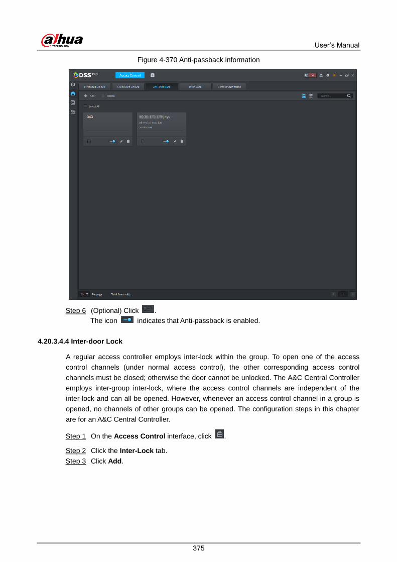
User’s Manual
375
Anti-passback information Figure 4-370
(Optional) Click . Step 6
The icon indicates that Anti-passback is enabled.
4.20.3.4.4 Inter-door Lock
A regular access controller employs inter-lock within the group. To open one of the access
control channels (under normal access control), the other corresponding access control
channels must be closed; otherwise the door cannot be unlocked. The A&C Central Controller
employs inter-group inter-lock, where the access control channels are independent of the
inter-lock and can all be opened. However, whenever an access control channel in a group is
opened, no channels of other groups can be opened. The configuration steps in this chapter
are for an A&C Central Controller.
On the Access Control interface, click . Step 1
Click the Inter-Lock tab. Step 2
Click Add. Step 3

User’s Manual
376
Inter-door lock configuration Figure 4-371
Configure inter-lock parameters and click OK. Step 4
Table 4-66 Parameters
Parameter Description
Device You can select the device to set up inter-lock.
Inter-lock name You can customize the name of the inter-lock rule.
Time Template You can select the time period to implement
inter-lock.
When the selected
device is a multi-door
controller, you must
set up these
parameters.
Remark Description information.
Group X
X is a number.
You can set up inter-lock across different door
groups. If a door in Group 1 is opened, no
doors can be opened in Group 2 until all doors
in Group 1 are closed.
Supports up to 16 door groups, with up to 16
doors in each group.
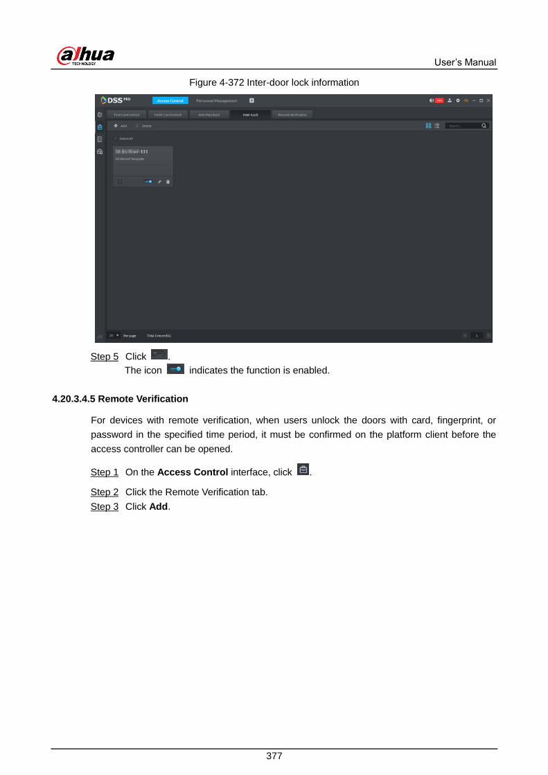
User’s Manual
377
Inter-door lock information Figure 4-372
Click . Step 5
The icon indicates the function is enabled.
4.20.3.4.5 Remote Verification
For devices with remote verification, when users unlock the doors with card, fingerprint, or
password in the specified time period, it must be confirmed on the platform client before the
access controller can be opened.
On the Access Control interface, click . Step 1
Click the Remote Verification tab. Step 2
Click Add. Step 3

User’s Manual
378
Add remote verification Figure 4-373
Select Time Template and access control channel, and click OK. Step 4

User’s Manual
379
Remote verification information Figure 4-374
Click . Step 5
The icon indicates Remote Verification is enabled.
After the setup, door unlocking by card, fingerprint, or password that takes place in the
corresponding access control channel triggers a pop-up on the client.
You can choose to unlock the door or ignore it by clicking the corresponding button, and
the popup automatically disappears.
4.20.4 Access Control Applications
4.20.4.1 Viewing Videos
If you have already bound a video channel to the access control channel, you can view the
real-time videos of the channels on the console. To bind video channels, see "3.4.6 Binding
Resource."
Log in to the Control Client, select Access Control > Console, and then view videos in the
following ways.
On the right side of the console interface, click in the access control channel list. The
system displays videos in real time.

User’s Manual
380
Click on the console interface. The system displays the video interface. Drag the
access control channel on the left side of the screen to the live view interface on the right
side. The system displays videos in real time.

User’s Manual
381
Real-time video Figure 4-375
4.20.4.2 Unlocking Door
In addition to Always Open or linked unlock in specified periods, the console also supports
unlocking by manually controlling the access control channel. After unlock, the door
automatically locks up after a specified period (5 s by default, and 10 s in this example) set up
in Door Config.
You can unlock the door in the following ways:
On the left side of the interface, right-click an access control channel in the device list, and
select Remote Unlock in the popup menu. After unlocking, the door status in the access
control channel list on the right side of the interface changes to open, as .

User’s Manual
382
Unlock door (1) Figure 4-376
Click on the door channel interface to unlock the door.
Unlock door (2) Figure 4-377
When viewing videos bound to the channel, click on the video interface to unlock the
door.
Unlock door (3) Figure 4-378
Temporary Always Open of multiple doors
Select door channels through global control, and then you can set the door to be Always
Open.

User’s Manual
383
Click on the lower left of the console interface of the Access Control module. Step 1
Select an access control channel to be set to Always Open via global control, and click Step 2
OK.
Click on the lower-left corner of the interface. Step 3
Global control Figure 4-379
Enter current user's password, and click OK. Step 4
All the doors of the selected access control channels are set to Always Open.
Click to restore the door from the Always Open or Always Closed status before
the scheduled door control or face-recognition access control takes effect.
4.20.4.3 Locking Door
In addition to Always Close or linked lock in specified periods, the console also supports locking
by manually controlling the access control channel. You can lock the door in the following ways:
On the left side of the interface, right-click an access control channel in the device list, and
select Remote Lock in the popup menu. After locking, the door status in the access
control channel list on the right side of the interface changes to closed, as .

User’s Manual
384
Lock door (1) Figure 4-380
Click on the door channel interface to lock the door.
Lock door (2) Figure 4-381
When viewing videos bound to the channel, click on the video screen to lock the door.
Lock door (3) Figure 4-382

User’s Manual
385
Temporary Always Close of multiple doors
Select a door channel through global control and you can set the door to be Always Close.
Click on the bottom left of the console interface. Step 1
Select an access control channel to be set to Always Close via global control, and click Step 2
OK.
Click at lower left of the interface. Step 3
Global control Figure 4-383
Enter current user's password, and click OK. Step 4
All the doors of the selected access control channels are set to Always Close.
Click to restore the door from the Always Open or Always Closed status before
the scheduled door control or face-recognition access control takes effect.
4.20.4.4 Viewing Event Details
View details of the events reported on door locking and unlocking, including: Event Info, Live
View, Snapshot, and Recording.
Live view is only available when a video channel is bound to the access control channel. To
bind video channels, see "3.4.6 Binding Resources."
To see snapshots and videos of access control, you need to configure video linkage action
for the access control channels. For details, see "4.4 Event and Alarm."
In the event list below the console interface, click next to the event records. Step 1

User’s Manual
386
For a face recognition controller, the face snapshots will be displayed in the records; for
other controllers, the records display people profiles.
Event information Figure 4-384
Table 4-67 More operations
No. Description
1 You can choose to view the events of certain event types. For instance, if you select
Normal, the list only displays normal events.
2 Click to stop displaying reported event information. In this case, the interface
no longer displays the reported new events. After clicking, the button changes to
.
Click to start refreshing reported event information. The interface does not
display events during the stopping period. After clicking, the button changes to
.
3 Clear the events from the current event list without removing them from the log.
4 Click to view access control records.
Click the corresponding tab to view the live view, snapshots, and video recordings of Step 2
the linked video channel.

User’s Manual
387
4.20.4.5 Viewing Access Control Records
You can view access control records. There are two types of records:
Online records
The access control records stored on the platform.
Offline records
The access control records stored in the device when it was disconnected from the
platform. After the device gets reconnected to the platform, you can retrieve the records
generated during the disconnection.
4.20.4.5.1 Online Records
Log in to the Control Client, and then select Access Control. Step 1
Click . Step 2
Set search conditions such as event type, channel, and time, and then click Search. Step 3
To export the searches, click Export at the upper-right corner of the interface. The
required password is the one for logging in to the platform.
Log search Figure 4-385

User’s Manual
388
4.20.4.5.2 Offline Records
Log in to the Control Client, and then select Access Control. Step 1
Click . Step 2
Click at the upper-right corner. Step 3
Extract records during disconnection Figure 4-386
Click to set period. Step 4
Click to select a record type. Step 5
Select a channel. Step 6
Click OK. Step 7

User’s Manual
389
Video Intercom 4.21
Video intercom plays an important role in modern community management. It enables
convenient communication and door control between visitors and residents.
4.21.1 Typical Topology
Access control typical topology Figure 4-387
VTH (indoor monitor) is installed in home for receiving visitor calls from VTO (door station)
or fence station, or security center (VTS or the DSS platform), calling other homes (VTHs)
or the security center, viewing videos at the door, and opening door.
VTO is installed at the building door for the visitor to call homes.
Locks are mounted on the door for door control.
Fence station is installed at the gate for the visitor to call the host.
Management station is deployed in the security center for receiving calls from visitors or
residents.
The platform centrally manages all devices (VTH, VTO, management station and fence
station), speaks with the devices, and provides record search.
4.21.2 Business Flow
Video intercom business flow Figure 4-388

User’s Manual
390
4.21.3 Configuring Video Intercom
4.21.3.1 Preparations
Make sure that the following preparations have been made:
Access control devices are correctly deployed. For details, see the corresponding user’s
manuals.
Basic configurations of the platform have been finished. To configure, see "3 Basic
Configurations." When adding video intercom devices on the Device interface of Web
Manager, select Video Intercom for device category.
The enable status of unit and building on the VTO must be consistent with that on the
platform. Or else you might fail to add VTO. For details, see “4.23.3.2 Configuring
Building and Unit.”
The system creates personnel information automatically when you add VTH. It
extracts room number from VTH SIP. This number is used as person ID. You can view
and modify personnel information on the interface Personnel Management interface.

User’s Manual
391
Any configuration modification on the device will not be reported to the platform. You
need to go to the device modification interface of Web Manager to manually
synchronize the modification.
Adding video intercom device Figure 4-389
4.21.3.2 Configuring Building/Unit
Make sure that the enable status of building and unit is in accordance with the device;
otherwise, the device is offline after being added. That also affects the dialing rule. Take room
1001 unit 2 building 1 as an example, the dialing rule is as follows after it is enabled.
If building is enabled while unit is not, the room number is "1#1001".
If building is enabled, and unit is enabled as well, the room number is "1#2#1001".
If building is not enabled, and unit is not enabled either, the room number is "1001".
Click on the Web Manager, and then select Video Intercom Management Step 1
Click Residence Config. Step 2

User’s Manual
392
Residence configuration Figure 4-390
Enable or disable building and unit as required, and then click Save. Step 3
4.21.3.3 Synchronizing Contacts
Synchronize contacts information to VTO and then you can view contacts on the VTO display
screen or WEB interface.
Click on the Web Manager, and then select Video Intercom Management. Step 1
Click Release Contact. Step 2
Select an organization node (VTO), and then click Release Contact. Step 3
Select VTH and click Save. Step 4
You can view contact on the VTO display screen or WEB interface after releasing is
completed.
4.21.3.4 Setting Private Password
Set room door passwords so that the room door can be opened by entering password on the
VTO (outdoor station).
Make sure that contacts are released to VTO; otherwise it will fail to set private password.
Click on the Web Manager, and then select Video Intercom Management. Step 1

User’s Manual
393
Click Private Password Setting. Step 2
Set private password (1) Figure 4-391
Select a VTO. Step 3
The VTHs bound to this VTO are displayed.
Set private password (2) Figure 4-392
Select a VTH, click or select several VTHs, click Batch Modify Password. Step 4

User’s Manual
394
Change password Figure 4-393
Enter password, and then click OK. Step 5
You can use the new password to unlock on the VTO.
4.21.3.5 APP User
View information of APP users, freeze user, modify login password and delete user.
APP user can register by scanning the QR code on VTH. For details, see DSS APP User's
Manual.
Click on the Web Manager, and then select Video Intercom Management. Step 1
Click APP User. Step 2
App user Figure 4-394
Table 4-68 Parameters

User’s Manual
395
Operation Description
Freeze APP
user
The APP user cannot log during 600 s after being frozen.
means normal status; means freezed. Click this icon to
switch between the two statuses.
The account will be frozen when invalid password attempts exceeds 5
by APP user.
Modify APP
user login
password
Click and enter new password on the interface of Reset
Passoword. Click OK.
The password shall be between 8 and 16 characters, including
number and letter.
means password can be seen while means password is
protected. Click icon to switch.
Delete APP
user
Click or select APP user (several users can be selected); click
Delete and the selected users will be deleted according to the
interface tips.
4.21.3.6 Call Management
Create device group, management group and relation group respectively and define restricted
call relations. This function is only available for the system account user.
Click on the interface of device group, management group or relation group, the system
will restore management group and relation group to original status.
4.21.3.6.1 Device Group Config
Realize mutual call only when VTO and VTH are added into the same device group. Pro will
automatically generate corresponding device group when VTO, verifying VTO and fence station
are added to Pro.
Add VTO and automatically generate a device group, add VTH of the unit into the group,
and realize mutual call between VTH and VTO within the group.
Add verifying VTO and automatically generate a device group, add it to the group together
with the VTH of the same room, and realize mutual call between VTH and verifying VTO
within the group.
Add fence station and automatically generate a device group, add all the VTH into the
group. Realize mutual call between fence station and all the VTH.

User’s Manual
396
Add VTH, if the VTH is automatically connected to unit VTO, verifying VTO, fence station,
and then it will be automatically added to the device group, and realize mutual call among
unit VTO, verifying VTO or fence station.
Call between VTH is not restricted by device group; mutual call can be realized among VTH in
different device groups.
4.21.3.6.2 Adding Management Group
Management group is to make groups for administrators, and realize relation binding of one to
one, one to many or many to many. Administrators include Pro administrator and VTS. If there
is default management group, VTS will be automatically added to management group when it is
added.
Before configuring management group, it needs to create user, select video intercom menu
permission and device permission, and add new users into management group.
Use system user to configure group relation, need to switch to new user for login. If system
logs onto many devices, then it cannot be used as administrator.
Click on the Control Client, and then select Video Intercom. Step 1
Video intercom Figure 4-395
Click . Step 2
Click Management Group Config. Step 3

User’s Manual
397
Management group configuration Figure 4-396
Click Add Group. Step 4
Edit manager group Figure 4-397
Enter group name, select administrator account or VTS, and click OK. Step 5
The added management group is displayed in the list.

User’s Manual
398
To transfer members, click and move the member to the group.
To manage group members, click to add or delete group member.
Added management group Figure 4-398
4.21.3.6.3 Group Relation Config
There are two situations for relation binding
Device group only binds one management group
Any device in the group can call administration with one click, all the bound administrators
within the management group will generate ring bell. At this moment, all other ring bell will
stop as long as there is on administrator answers. The device call request can be rejected
as long as all the administrators reject to answer.
Device group binds several management groups
There is priority among several management groups. When any device in the group calls
administrator with one click, and all the online administrators of management group with
highest priority will generate ring bell. If none of these administrators answer, then it will
call next management group. The interval between two calls is 30s; it can skip up to one
management group. If neither of two groups answer, then the device prompts call overtime,
no response.
Click on the Control Client, select Video Intercom, and then click . Step 1
Click Relation Group Config. Step 2

User’s Manual
399
Relation group configuration Figure 4-399
Click Add. Step 3
Figure 4-400
Enter name, select device group and management group, and then click OK. Step 4

User’s Manual
400
Added relation group is displayed in the list. If there are several relation groups, you
can click or to adjust priority level. When there is call, the online administrators
with high priority will generate ring bell first.
Added relation group Figure 4-401
4.21.4 Video Intercom Applications
4.21.4.1 Call
Realize call among Pro, VTO and VTH.
Click on the interface of Video Intercom. Step 1

User’s Manual
401
Call center Figure 4-402
You can call VTO and VTH on the interface of Call Center. Step 2
Call from the platform to VTO
Select VTO in the device list; click corresponding of VTO and call VTO. The
system pops out call interface. The following operations are support during call.
If VTO is connected to lock, click to unlock.
Click to capture picture, the snapshot is saved into the default directory
installed by client. If you need to modify the save path of snapshot, see "4.1.4
Local Configuration" for more details.
Click to start record, click again to stop record. The video is saved in
default path installed by client. If you need to modify the save path, see "4.1.4
Local Configuration" for more details.
Click to hang up.

User’s Manual
402
Call Figure 4-403
Call from the platform to VTH
Select VTH from the device list, click on the VTH or dial corresponding VTH
on the right (such as 1#1#101). The system pops up the dialog box of Calling now,
please wait …. There are two modes for answering the call.
Answer by VTH, bidirectional talk between client and VTH. Press to
hang up when you answer the call.
If VTH fails to answer over 30s, busy or hang up directly, then it means the call
is busy.

User’s Manual
403
Calling Figure 4-404
Call from VTO to the platform
VTO calls Pro, client pops up the dialog box of VTO calling.
If VTO is connected to lock, click to unlock.
Click to answer VTO, realize mutual call after connected.
Click to hang up.

User’s Manual
404
VTO Call Figure 4-405
When VTH is calling the paltform
The client pops out the dialog box of VTH calling. Click to talk with
VTH.
Click and answer VTO, realize mutual talk after connected.
Click and hang up.

User’s Manual
405
VTH call Figure 4-406
Call through call records
All the call records are displayed in the Call Record at the lower right corner of the
interface of Video Intercom. Move the mouse pointer to the record, click
and call back.
Call records Figure 4-407

User’s Manual
406
4.21.4.2 Information Release
Send message to designated VTH.
Click on the interface of Video Intercom. Step 1
Release interface Figure 4-408
Click Add New Message, select VTH and add release information. Step 2
Add new message Figure 4-409

User’s Manual
407
Click Send. Step 3
The VTH will receive the message after it is sent successfully.
4.21.4.3 Video Intercom Logs
View log records and you can trace recorded calls.
Enter the interface of video intercom log. Step 1
Click on the interface of Video Intercom.
Click and enter console on the interface of Video Intercom.
Enter console Figure 4-410
Set conditions, and then click Search. Step 2

User’s Manual
408
Logs Figure 4-411
Click Export and the logs will be saved locally according to system prompt. Step 3

User’s Manual
409
Attendance Management 4.22
Configure attendance settings such as attendance devices, attendance shifts and periods, so
as to manage attendance records and reports.
4.22.1 Typical Topology
Attendance management typical topology Figure 4-412
Attendance devices are used for recording checking in or out in the way of face recognition,
swiping card or more.
The platform centrally manages all devices and attendance rules, and provides attendance
analysis.

User’s Manual
410
4.22.2 Business Flow
Attendance business flow Figure 4-413
4.22.3 Configuring Attendance
4.22.3.1 Preparations
Make sure that the following preparations have been made:

User’s Manual
411
Attendance devices are correctly deployed. For details, see the corresponding user’s
manuals.
Basic configurations of the platform have been finished. To configure, see "3 Basic
Configurations."
When adding attendance devices on the Device interface of Web Manager, select
Access Control for device category.
Add device Figure 4-414
Personnel information is added correctly. For details, see “4.19 Personnel
Management.”
4.22.3.2 Setting Attendance Terminal
Make sure that access controller is used as attendance device for check-in and check-out,
recording attendance information, and uploading attendance data.
Click and select Attendance Management. Step 1

User’s Manual
412
Attendance management Figure 4-415
Click at the lower-left corner of the interface, and then select Attendance Step 2
Terminals.
Attendance terminal Figure 4-416
Select access control channel from the left list, and then click Save. Step 3
You can find needed devices by search. The system supports fast search.

User’s Manual
413
4.22.3.3 Setting Statistics Rule
Minimum timing unit of swiping card is minute, the statistics rule of dealing with second is round
up and round down. For example, swipe card at 09:00:01, if the rule is set as round down, then
the time of swiping card is 09:00; if the rule is set as round up, then the time of swiping card is
09:01.
Click at the lower left corner on the interface of Attendance Management, select Step 1
Statistics Rule.
Statistical rule Figure 4-417
Select rule and click Save. Step 2
4.22.3.4 Setting Attendance Period
Set attendance period, which can be used as time evidence to judge if people attend, arrive late
or leave early.
Click on the interface of Attendance Management. Step 1

User’s Manual
414
Attendance period Figure 4-418
Click on upper-left corner of the interface. Step 2
The new attendance period interface is displayed.
Set parameters of attendance period. Step 3
The priority of rules set by Pro is higher than that of the device itself.
There are two types of attendance according to different attendance modes and
different configurations.
Fixed attendance requires you to sign in and sign out during the fixed hours.

User’s Manual
415
Set attendance time (one working period) Figure 4-419
Set attendance time (two working periods) Figure 4-420
Table 4-69 Fixed attendance parameters
Parameter Description
Period Name Custom period name, used to recognize period, such as early shift and
night shift.
Color Set corresponding color of period, corresponding color will be directly
displayed on calendar when making shift for personnel, and quickly

User’s Manual
416
Parameter Description
recognize shift information.
Attendance Mode Set as Fixed Attendance.
Working Time
Set corresponding working hour of period. Attendance time supports
cross-day, but not exceeds 24 hours. One attendance period supports
max two types of attendance time.
If attendance time needs to be split into twice, such as morning
and afternoon, then it needs to click , set second working time
and sign-in sign-out period.
If you set two types of attendance time, then it needs to sign in
and sign out according to the configured attendance time, which
can be considered as normal attendance.
Working Hour Please fill in according to actual situation.
Valid Sign-in Time
If working time is set from 09:00-18:00, then valid sign-in time can be
set as 08:00-10:00, valid sign-out time can be set as 16:00-18:00.
Configuration rules are as follows:
The start time of valid sign-in time is earlier than or equal to start
working time (09:00), the end time of valid sign-in time should be
later than start working time (09:00), earlier than start time of valid
sign-out time. If there are several sign-in records within valid
sign-in time, then the earliest record is considered as sign-in time.
The start time of valid sign-out time is later than the end time of
valid sign-in time, earlier than end working time (18:00), the end
sing-in time of valid sign-out time is later than or equal to end
working time (18:00). If there are several sign-out records within
valid sign-out time, then the earliest record is considered as
sign-out time.
Valid Sign-out Time
Shall sign in
If you set two working time, then the second working time can cancel
sign in, you don’t have to sign in when you work at the second working
time, and the start time of working time can be used as sign-in time.
Shall sign out
If you set two working time, then the first working time can cancel sign
in, you don’t have to sign out when you finish work at the second
working time, and the end time of working time can be used as
sign-out time.
Late sign-in within
_minutes is
permitted
Define the rules for being late, absence and early leave.
Suppose set Work sign-in over__minutes recorded as late as 5
minutes; Late sign-in over _minutes recorded as absence is set as
60 minutes; Off duty _ minutes in advance recorded as early leave
is set as 10 minutes; Early
leave exceeds_ minutes recorded as absence is set as 30 minutes.
Late sign-in over
_minutes recorded
as absence

User’s Manual
417
Parameter Description
Early leave within_
minutes is
permitted
Details are as follows.
Late
When work sign-in is later than start time of working time,
and 5 minutes< period ≤60 minutes, then it is recorded as late.
Early leave
When off duty sign-out time is earlier than end time of working
time, and 10 minutes< period ≤30 minutes, then it is recorded as
early leave.
Absence
When work sign-in time is later than start time of working time,
and period > 60 minutes, then it is recorded as absence.
When off duty sign-out time is earlier than end time of working
time, and period> 30 minutes, then it is recorded as absence.
Early
Sign out over _
minutes is recorded
as absence
End of Off Duty
_minutes later than
off duty time is
recorded as
overtime
Define overtime rule.
Suppose Off duty sign-out over__minutes recorded as overtime is
set as 120 minutes, off duty sign-out time is later than end time of
working time, and period >120 minutes, then it is recorded as
overtime, overtime period is Period – 120 minutes.
Free attendance just calculates whether the daily working hours of a person meets
the rule according to the sign-in/out time.
Configure free attendance Figure 4-421
Table 4-70 Free attendance parameters
Parameter Description
Period name Custom period name, used to recognize period, such as flexible
attendance.

User’s Manual
418
Parameter Description
Attendance mode Set as Free Attendance.
Color
Set corresponding color of period, corresponding color will be
directly displayed on calendar when making shift for personnel,
and quickly recognize shift information.
Hour system Set how many hours you have to work a day. For example, if you
set 8, then it means you are required to work 8 hours.
Final punch in
time Sign in after restricted time is recorded as late.
Mark as_working
hour Fill in working hour according to actual situation.
Final punch out
time
You are required to sign out before the designated time, otherwise
no sign out is recorded.
Overtime Working over__ hours is recorded as overtime. For example,
working hour is 8 hours a day, and if you work overtime for 2.5
hours, then it is recorded as overtime, then you can set 10.5 here.
Work over_hours
recorded as
overtime
Odd in even out Swipe card at odd number is recorded as sign-in. For example,
the first card-swiping is sign-in. Swipe card at even number is
recorded as sign-out. For example, the second card-swiping is
sign-out. It is recorded as twice card-swiping when the interval of
continuous twice card swiping is bigger than the threshold.
Continuous twice
card swiping
interval≥_minutes
Click Save and save period configuration. Step 4
If attendance period is already applied to attendance shift, then before deleting
attendance period, enter the interface of Attendance Shift, modify attendance shift,
and delete attendance period.
4.22.3.5 Setting Holidays
Set holiday time, used to judge overtime type during attendance statistics.
Click on the interface of Attendance Management. Step 1

User’s Manual
419
Holiday management Figure 4-422
Click at the upper-left corner of the interface. Step 2
Add a holiday Figure 4-423
Set holiday details, three modes available. Step 3
Table 4-71 Holiday parameters
Holiday mode Description
Fixed Date Set some specific date as holiday. For example, set June 7, 2019 (Dragon

User’s Manual
420
Holiday mode Description
Boat Festival) as holiday, and lasts for 1 day, then set Start Date as June
7, 2019 and Holiday Days as 1.
Date Cycle
If the holiday is the fixed weekday of some week in some specific month,
and it cycles according to year, which can be configured as date cycle. For
example, if you want to set Mother’s Day as holiday, and it lasts for 1 day,
then you can set Start Date as the second Sunday in May, and Holiday
Days as 1.
Year Cycle
If the holiday is fixed date and it cycles according to year, which can be
configured as year cycle. For example, set New Year’s Day as holiday,
and it lasts for 1 day, then you can set Start Date as January 1 and
Holiday Days as 1.
Click Save. Step 4
4.22.3.6 Setting Attendance Shift
Set attendance shift according to attendance period, used for department and personnel shift.
Click on the interface of Attendance Management. Step 1
Attendance shift Figure 4-424
Click on the upper-left corner of the interface. Step 2
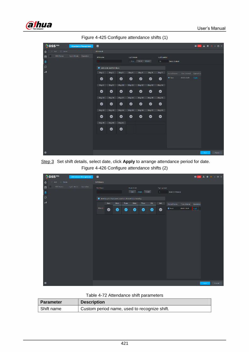
User’s Manual
421
Configure attendance shifts (1) Figure 4-425
Set shift details, select date, click Apply to arrange attendance period for date. Step 3
Configure attendance shifts (2) Figure 4-426
Table 4-72 Attendance shift parameters
Parameter Description
Shift name Custom period name, used to recognize shift.

User’s Manual
422
Parameter Description
Cycle mode
Day: Start cycle from the first day, cycle period can be set as any
number from 1 to 31 according to day. For example, if you set 2,
then the cycle period is 2 days.
Week: There are 7 days in a week by default, it starts cycle from
Sunday, and so Sunday is required to be set as the first day. Cycle
period can be set as any number from 1 to 4. For example, if you
set 2, then 2 weeks can be a cycle period.
Month: There are 31 days in a month by default, it starts cycle
from the current day (If the date does not exist, then it will be
deleted during shift arrangement), cycle period can be set as any
number from 1 to 3 according to month. For example, if you set 2,
then 2 months can be a cycle period.
Cycle period
Click Save to save shift configuration. Step 4
Delete in-use attendance shift: Go to the Personnel Shift Arrangement interface,
check if there are shifts to be deleted; if yes, remove the relation, and then delete.
4.22.3.7 Shift Management
Make shifts for personnel or department, meanwhile it makes temporary shift for personnel.
The shift priority is temporary shift > holiday > personnel shift > department shift.
4.22.3.7.1 Personnel/Department Shift Arrangement
The operations over both personnel shift and department shift are similar, in this chapter; it
takes personnel shift as an example to introduce configuration.
If you configure department shift, then all the personnel of the department need to conform
to the shift.
If both personnel and department are configured with shift, then the latest personnel shift
shall prevail. For example, after configuring the personnel shift, and the corresponding
department is configured as well, then personnel shift is based on the latest department
shift.
If the department where new personnel belong to is configured with shift, then the shift of
new personnel should conform to department shift.
Click on the interface of Attendance Management. Step 1

User’s Manual
423
Personnel shift arrangement (1) Figure 4-427
Click on the upper-left corner of the interface. Step 2
If you need to configure shift for department, click on the upper-left corner
and enter the interface of department shift arrangement. The following operation
is the same as personnel shift arrangement.
On the interface of personnel shift arrangement, select personnel and view the
shift situation.
Click next to the personnel and you can view the shift details.

User’s Manual
424
Personnel shift arrangement (2) Figure 4-428
Select shift personnel, click to add shift information. Step 3
Select shifts Figure 4-429
Table 4-73 Shift parameters

User’s Manual
425
Parameter Description
Start time Set start date and end date of personnel shift. Click the
column of Start Time and display calendar, select date
and time, and then click OK to complete date setting
End time
Shift Select needed shifts. Shift range means all the attendance
shifts set in "4.22.3.6 Setting Attendance Shift."
Click Save. Step 4
4.22.3.7.2 Temporary Shift
Temporary shift is needed when work changes temporarily.
Click on the interface of Attendance Management or select personnel on the Step 1
right, Double-click date on the left.
Temporary shift interface Figure 4-430
Select personnel and date, click and select temporary attendance period. You can Step 2
add max. 2 attendance periods and 1 free attendance period.

User’s Manual
426
Temporary shift Figure 4-431
Click OK and save shift information. Step 3
Temporary shift can be deleted, right-click the date which is configured with temporary
shift, and delete temporary shift according to system prompt.
4.22.4 Viewing Attendance Report
View attendance data, displayed in the form of report, including card swiping record table,
attendance report, abnormity table, overtime table and away table.
Click on the interface of Attendance Management. Step 1

User’s Manual
427
Attendance report Figure 4-432
Click corresponding tab, set search condition, click Search. Step 2
Card swiping records. Click and view more details of the person who swipes
card.
Card-swiping records Figure 4-433
Attendance report

User’s Manual
428
Attendance report Figure 4-434
Abnormity table
Abnormity table Figure 4-435
Overtime table

User’s Manual
429
Overtime table Figure 4-436
Away table
Away table Figure 4-437
Visitor Management 4.23
After appointment is made on platform, and visitor information is registered, the visitor can have
access permission. Access permission is disabled after the visitor leaves.

User’s Manual
430
4.23.1 Preparations
Access control devices have been added into the system. For details, see "3.4 Managing
Device."
Basic configurations of the platform have been finished. To configure, see "3 Basic
Configurations."
4.23.2 Business Flow
Visitor management business flow Figure 4-438
4.23.3 Configuring Visit Settings
Configure the default parameters of visit, including, automatic visit, automatic leave, and
default permissions.

User’s Manual
431
Log in to the client, click , and then select Visitor Management. Step 1
Click . Step 2
Set parameters. Step 3
Set visit parameters Figure 4-439
Table 4-74 Description
Parameter Description
Automatic
Visit
Enable If enabled, in the appointed period, the visitor can show the
pass to get in or drive in (based on ANPR), without having
to register. Beyond the appinted period, the visitor still
needs to register.
Register
Automatic
Leave
Enable After Automatic Leave and Number Plate enabled, in the
valid period, the visitor can leave without registering. Register
Sign out
Expired
Visitors
The system automatically signs out the expired visitors at
the defined time point.
For those who have not visited as appointed before the
daily automatic sign-out time, the appointments will be
cancelled.
Daily Sign-out
Time

User’s Manual
432
Parameter Description
Sign out Now
Sign out the expired visitors right now.
For those who have not visited as appointed, the
appointments will be cancelled.
Visitor Default
Permissions
Enable
Set the default access permissions for visitors.
Access
Control
Video
Intercom
Entrance
Click Save. Step 4
4.23.4 Visitor Appointment
Register visitor information on the platform.
Log in to the Control Client, click , and then select Visitor Management. Step 1
Click Appointment Registration. Step 2
Click the Visitor Details tab, enter the information of the visitor and the one to be Step 3
visited.

User’s Manual
433
Appointment registration Figure 4-440
(Optional) Click the Authentication tab, select the room number to be visited, and then Step 4
click Generate to generate the QR code of the pass.
You can click to download the QR code, and click to send it to the visitor by
email.
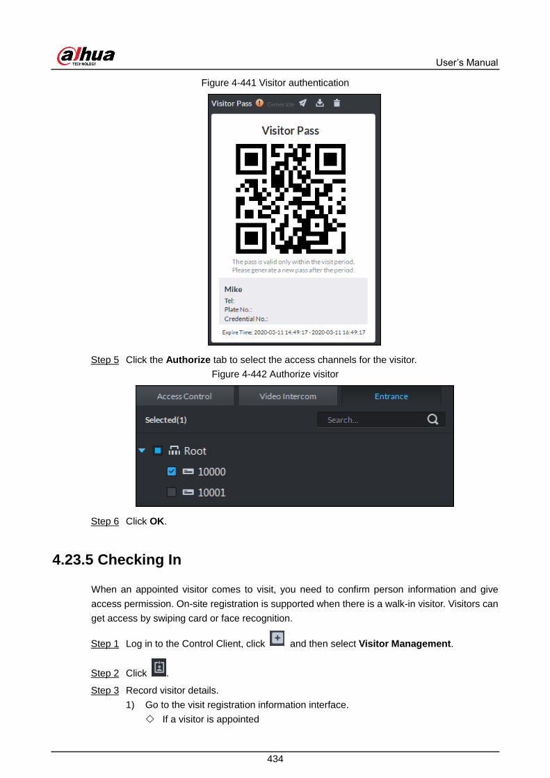
User’s Manual
434
Visitor authentication Figure 4-441
Click the Authorize tab to select the access channels for the visitor. Step 5
Authorize visitor Figure 4-442
Click OK. Step 6
4.23.5 Checking In
When an appointed visitor comes to visit, you need to confirm person information and give
access permission. On-site registration is supported when there is a walk-in visitor. Visitors can
get access by swiping card or face recognition.
Log in to the Control Client, click and then select Visitor Management. Step 1
Click . Step 2
Record visitor details. Step 3
1) Go to the visit registration information interface.
If a visitor is appointed

User’s Manual
435
Find the visitor information, and then click .
If a visitor is not appointed
Click Visit Registration.
2) Confirm or enter visitor information.
Visit information Figure 4-443
Click the Authorization tab, and then set authorization information. Step 4
1) Select the room number.
2) Issue cards.
You can issue cards by entering card No. manually or by using a card reader. Card
No. supports 8 and 16 digits. If the card No. is less than 8 or 16 digits, the platform
adds 0 by default to meet the digit number requirement. For example, if you enter
card number 8004, then the platform will change it to 00008004. If you enter card
number 1000056821, then the platform will change it to 0000001000056821.
Issue cards by entering card No. manually
Click Add next to Card, enter the card number, click OK.
Issue card Figure 4-444
Issue card by using a card reader

User’s Manual
436
Click , select a card reader or device, and then click OK. Swipe card on
reader or device, and card is issued.
Reader manager Figure 4-445
3) Set face pictures. Hover over the face snapshot area, click Upload Picture to
select a picture or click Snapshot to take a phone.
Click , and then you can select snapshot camera, pixel format, resolution and
set image quality. This is only effective with the current client.
Take a face snapshot Figure 4-446
4. Click Generate to generate the QR code pass.
You can click to download the QR code, or click to send the code to the
visitor by email.
Click the Authorize tab to select the access channels for the visitor. Step 5

User’s Manual
437
Authorize visitor Figure 4-447
Click OK. Step 6
Click to end visit.
Click to view visitor card swiping records.
4.23.6 Checking Out
When visitors are leaving, close their access permissions.
On the Visitor Management interface, click . Step 1
Find the appointment record of the visitor, and then click . Step 2
End visit Figure 4-448
Click OK to close the access permission. Step 3
If you have issued a card to visitor, Make sure that the card is returned when the visitor
leaves.

User’s Manual
438
4.23.7 Searching for Visit Records
Search for visit records, and view visitor details and the card swiping records.
On Visitor Management interface, click . Step 1
Set search conditions, and then click Search. Step 2
The results are displayed.
In addition to entering card number manually, you can also click , select a card
reader and then get the card number by swiping card.
Search visit result Figure 4-449
Click to view visitor details and card swiping records. Step 3
Business Intelligence 4.24
Analyze customer flow in your store so that you can optimize your business strategy
accordingly.
Entrance analysis
View the entry and exit numbers of customers.
Customer analysis
Analyze customer flow by gender and age.
Indoor analysis

User’s Manual
439
View customer numbers and stay numbers on each floor.
4.24.1 Typical Topology
Business intelligent typical topology Figure 4-450
Fisheye and people counting cameras count people numbers and provide full views of
areas.
Face recognition cameras detect and recognize people faces.
(Optional) NVR can be used for managing fisheye camera.
The platform centrally manages the devices and provides videos and record search.

User’s Manual
440
4.24.2 Business Flow
Business intelligence business flow Figure 4-451
4.24.3 Configuring Business Intelligence
4.24.3.1 Preparations
Make sure that the following preparations have been made:
Fisheye, face recognition, and people counting cameras are well deployed. For details,
see the corresponding user's manuals.
Basic configurations of the platform have been finished. To configure, see "3 Basic
Configurations."
When adding cameras on the Device interface of Web Manager, select Encoder for
device category.

User’s Manual
441
Add device Figure 4-452
After the fisheye camera or people counting camera is added, click , and then select
People Counting for Features.
Edit camera features (1) Figure 4-453

User’s Manual
442
After the face recognition camera is added, click , and then select Face Detection or
Face Recognition for Features.
Edit camera features (2) Figure 4-454
4.24.3.2 Adding Stores
Log in to the Web Manager, click , and then select Store Management. Step 1
Click Add to open the Add Store interface. Step 2
Name the store, select an organization, and then click Upload Map to upload a store Step 3
map.
Select the fisheye camera, drag it from the device tree to the map, and then select Step 4
People Counting for Camera Type.
Double-click the camera on the map to modify camera type.
Draw detection regions. Step 5
Support passenger flow analysis region and angle analysis region.
Passenger flow analysis.
1) Select Add Zone > Passenger flow Analysis, and then draw a region on the
map.
2) Set a zone name, select a fisheye camera and the camera zone, and then click
OK.

User’s Manual
443
In this way, the fisheye camera zone and the store area is bound, and then data
displayed in the store areas come from the bound fisheye camera zone. After the
configuration, store information is displayed in the store list. See Figure 4-457.
Configure passenger flow zone Figure 4-455
Angle analysis
Analyze the number of people going to different shelves inside the store.
1) Select Add Zone > Passenger flow Analysis, and then draw a zones on the map
according to the people flow directions.
2) Set a zone name, select a fisheye camera and the camera zone, adjust the
direction, and then click OK.
In this way, the fisheye camera zone and the store area is bound, and then data
displayed in the store areas come from the bound fisheye camera zone. After the
configuration, store information is displayed in the store list. See Figure 4-457.

User’s Manual
444
Configure angle analysis zone Figure 4-456
Store details Figure 4-457
(Optional) click , add multiple floors, and then repeat the previous steps to complete Step 6
adding the store maps.
Up to 10 floors can be added.
Click , follow the onscreen instructions, and then click OK. Step 7
Other Operations
Edit a store
Click of a store, and then edit store details. Support modifying the map.
Delete a store
Select the stores to be deleted. Click . The stores are deleted in batches.

User’s Manual
445
Click , and then you can delete a single store.
Move a store to another organization
Select the store, click , select an organization, and then click OK. The store is moved
to the new organization.
4.24.3.3 (Optional) Configuring Weather Report
If your platform is connected to the Internet, you can view weather report. Step 1
Log in to the Web Manager, click , and then select Store Management. Step 2
Click of a store in the store list, enter store location and country, and then click OK. Step 3
Configure weather parameters Figure 4-458
4.24.4 Business Intelligence Applications
4.24.4.1 Entrance Analysis
View the entry and exit numbers of customers.
On the Homepage interface of the Control Client, select Business Intelligence. Step 1
Click the Entrance Analysis tab. Step 2

User’s Manual
446
Entrance analysis Figure 4-459
Select a store from the organization tree, and then set search time. Step 3
Support searching by year, month and day.
Click Search. Step 4
The statistics data is classified by Entry, Exit, Stay and Entering Rate.
The result includes the total customer flow data and entrance flow data.

User’s Manual
447
Entrance analysis Figure 4-460
4.24.4.2 Customer Analysis
Analyze customer flow by gender and age.
On the Homepage interface of the Control Client, select Business Intelligence. Step 1
Click Customer Demographic. Step 2

User’s Manual
448
Customer statistics Figure 4-461
Select a store from the organization tree, and then set search time. Step 3
Support searching by year, month and day.
Click Search. Step 4
The result displays statistics data by customer age sections and by gender-weather
relation.

User’s Manual
449
Customer statistics Figure 4-462
4.24.4.3 Indoor Analysis
View customer numbers and stay numbers on each floor.
On the Homepage of the Control Client, select Business Intelligence. Step 1
Click Indoor Analysis. Step 2

User’s Manual
450
Indoor analysis interface Figure 4-463
From the organization tree on the left, select a store, set search time, and then click Step 3
Search.
Click the floor name to switch to another floor and view the corresponding data.
The Area Flow Statistics section shows flow statistics data. If there is no data in
an area, it will not show this area.
In the People Flow Trend section and Dwell Time Trend section, you can click
Statistics Area to select an area to be displayed. The section only displays data of
the selected floor. If there are more than 10 statistics areas, only the top 10 areas
will be displayed.

User’s Manual
451
Indoor analysis Figure 4-464
Alarm Controller 4.25
After adding alarm controllers to platform, you can manage and configure alarm zones and sub
systems centrally.
4.25.1 Preparations
Alarm controllers have been added into the system. For details, see "3.4 Managing
Device."
Basic configurations of the platform have been finished. To configure, see "3 Basic
Configurations."
When adding alarm controllers on the Device interface of Web Manager, select Alarm
Host for device category.

User’s Manual
452
Add an alarm controller Figure 4-465
After adding alarm controllers, Modify zone types, click to modify the features of zones.
For example, for a smoke detection zone, select Smoke Sensor as the alarm type. The
alarm types can be customized. Select Customized Alarm Type in the Alarm Type
drop-down list and then set the type details as needed. After alarm type configuration, you
can configure the corresponding event types for the zones.

User’s Manual
453
Set zone type Figure 4-466
4.25.2 Alarm Controller Interface
Click , and then select Alarm Controller on the client homepage. The Alarm Controller
interface is displayed.

User’s Manual
454
Alarm controller interface Figure 4-467
Table 4-75 Alarm controller interface description
No. Name Description
1 Device list
Display all alarm controller devices and subsystems under device.
Icon status of subsystem
, no zone under subsystem.
, zone exists under subsystem
The subsystem and zone information displayed on platform can be
acquired from device; the platform does not support config.

User’s Manual
455
No. Name Description
2 Subsystem
and zone list
Clicking on an alarm controller name in the device tree, its
subsystems and the zones not yet added to subsystems will be
displayed on the right.
Clicking on a subsystem name, the zones in this subsystem will
be displayed on the right.
The description of icon status is shown as follows.
Zone status icon
, arm.
, disarm.
, bypass.
, isolate.
Subsystem status icon
, all zones armed under subsystem.
, all zones disarmed under subsystem.
, zones are not distributed by subsystem.
, some zones under subsystem are armed.
3 Select all Select all subsystems and zones displayed in list.
4 Operation
button Operation buttons supported by zone or subsystem.
5 Filter button Click the button, the subsystem and zone of corresponding status
are displayed in the list.
4.25.3 Updating Alarm Controller Status
In the device tree area, right-click the alarm controller that needs to be updated, and then select
Update Alarm Controller.
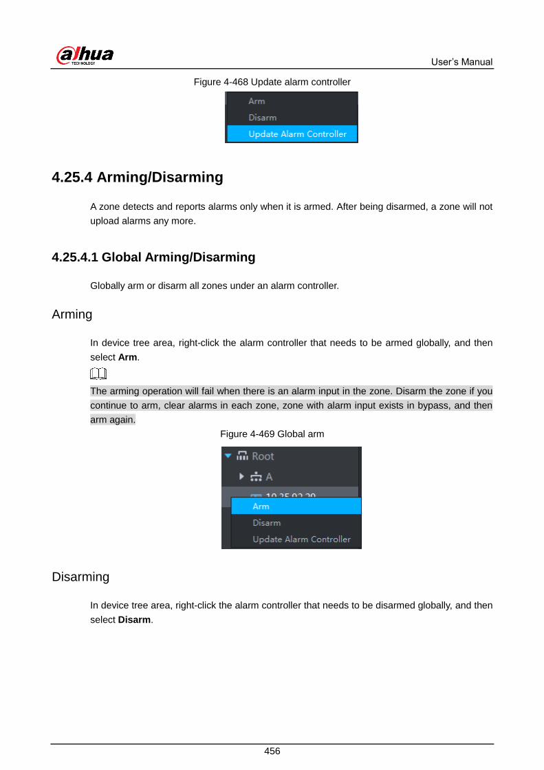
User’s Manual
456
Update alarm controller Figure 4-468
4.25.4 Arming/Disarming
A zone detects and reports alarms only when it is armed. After being disarmed, a zone will not
upload alarms any more.
4.25.4.1 Global Arming/Disarming
Globally arm or disarm all zones under an alarm controller.
Arming
In device tree area, right-click the alarm controller that needs to be armed globally, and then
select Arm.
The arming operation will fail when there is an alarm input in the zone. Disarm the zone if you
continue to arm, clear alarms in each zone, zone with alarm input exists in bypass, and then
arm again.
Global arm Figure 4-469
Disarming
In device tree area, right-click the alarm controller that needs to be disarmed globally, and then
select Disarm.

User’s Manual
457
Global disarm Figure 4-470
4.25.4.2 Arming/Disarming a Zone/Subsystem
Arm or disarm a single zone or subsystem.
Arming
The arming operation will fail when there is an alarm input in the zone. Disarm the zone if
you continue to arm, clear alarms in each zone, bypass the zone with alarm input, and then
arm again.
If a subsystem has no zone, then you cannot arm or disarm it.
You can arm by the following two methods:
Click the zone you want to arm or of the corresponding subsystem, and then select
Arm.
Arm a zone Figure 4-471

User’s Manual
458
Arm a subsystem Figure 4-472
Select the zone or subsystem you want to arm (multiple choice supported), and then click
Arm on the top of the interface.
Arm Figure 4-473
Disarming
Support disarming by the following two methods.
Click the zone you want to disarm or of the corresponding subsystem, and then
select Disarm.
Disarm a zone Figure 4-474

User’s Manual
459
Disarm a subsystem Figure 4-475
Select the zone or subsystem you want to disarm (multiple choice supported), and then
click Disarm on the top of the interface.
Disarm Figure 4-476
4.25.5 Bypassing/Isolating/Normal
When a zone is bypassed, the alarm controller still monitors the zone but will not forward
the zone data to users. If you want to arm the bypassed zone, disarm the zone into
non-bypass and arm again.
When a zone is isolated, the alarm controller still monitors the zone but will not forward the
zone data to users. When the zone is disabled or you want to disarm and arm again, the
isolated zone is still disabled.
When a zone is in the status of Normal, the zone can trigger alarms normally when it is
armed.
Two ways to arm/disarm a zone:
Click of the zone that needs to be bypassed, isolated or recovered to normal, and
then select operation.

User’s Manual
460
Bypass/isolate a zone (1) Figure 4-477
Select the zone that needs to be bypassed, isolated or recovered normal (multiple choice
supported), and then click the operation buttons on the top of the interface.
Bypass/isolate zone (2) Figure 4-478
4.25.5.2 Cancelling Alarms
You can remove an alarm by Cancel Alarm when the alarm is triggered.
Click the zone you want to cancel alarm, and then select Cancel Alarm.

User’s Manual
461
Cancel alarms Figure 4-479
Select the zone you want to cancel alarms from (multiple choices supported), and then
click Cancel Alarm on the top of the interface.
Cancel alarms (2) Figure 4-480

User’s Manual
462
Configuring N+M 4.26
To configure N+M, enable slave servers on the master server and confirm the relation between
slave servers and spare servers.
Make sure that all servers are well deployed before starting to configure N+M.
Log in to the Web interface of the master server. Step 1
Click , and then select Server Management > Server Config. Slave servers are Step 2
disabled by default.
Click next to each slave server to enable all the slave servers. Step 3
When disabled, server status is shown as Offline; when enabled and if the server
works normally, its status is shown as Running.
Enable slave servers Figure 4-481
Set specific servers to be spare servers. Step 4
1) Click of each slave server.
2) Select Spare Server in the Server Type dropdown list. Click OK.

User’s Manual
463
Configure server (1) Figure 4-482
Configure the relationship between slave servers and spare servers. Step 5
Support the following two methods to configure.
Go to the Configure Server interface of the slave server, and then select spare
servers. See instructions below.
1) Click of the slave server.
The Configure Server interface is displayed.
2) Select one or more spare servers in the Select Spare Server(s) list.
The selected servers are listed on the right. Click to adjust the priority.

User’s Manual
464
Configure server (2) Figure 4-483
3) Click OK.
Go to the Configure Server interface of the spare server, and then select slave
servers. See instructions below.
1) Click of the spare server.
The Configure Server interface is displayed.
2) Select one or more slave servers from the Select Slave Server(s) list.
The selected servers are listed on the left. Click to adjust the priority.

User’s Manual
465
Configure server (3) Figure 4-484
3) Click OK.
Cascade 4.27
The system supports cascading. After cascading, platform of higher level can view the live
video and video record of platforms of lower level. Configuring cascade refers to adding
lower-level platforms to higher-level ones. The system supports up to 3 levels.
Before configuring, make sure that the platform is deployed.
Currently, the systems supports cascading between Pro and Express platforms. Express
can only be lower-level platform.

User’s Manual
466
4.27.1 Typical Topology
Typical topology Figure 4-485
Network Cable
IPC Speed
Dome
IPC
DSS Pro (Master)
DSS Pro (Slave) DSS Pro (Slave)
IPC Speed
Dome
IPC
...
Head Quarter
IPC Speed
Dome
IPC
DSS Pro (Master)
DSS Pro (Slave) DSS Pro (Slave)
IPC Speed
Dome
IPC
...
Site A
IPC Speed
Dome
IPC
DSS Pro (Master)
DSS Pro (Slave) DSS Pro (Slave)
IPC Speed
Dome
IPC
...
Site B
4.27.2 Configuring Cascade
Click on the Web Manager, and then select Domain. Step 1

User’s Manual
467
Domain Figure 4-486
Click Add. Step 2
Add cascading Figure 4-487
Configure the parameters, and click OK to save the configuration. Step 3
Org refers to the higher-level platform that the added platform belongs to.
If there is more than one level of platform, repeat this process. Step 4

User’s Manual
468
System Configuration 4.28
Configure system settings such as email and device login mode.
4.28.1 HTTPs Certificate
HTTPS (Hyper Text Transfer Protocol over Secure Socket Layer) is a safe HTTP transmission
protocol. It provides safe and stable guarantee of user information and device security. When
HTTPS certificate is configured, you can log in to the platform through HTTPS protocol to
ensure transmission security.
SSL certificate is created or purchased, and you have got the password.
Log in to the Web Manager, click , and then select System. Step 1
Click the HTTPS tab. Step 2
HTTPs certificate Figure 4-488
Click Browse, import SSL certificate, and then enter the password. Step 3
Click Save. Step 4
4.28.2 Setting Mail Server
Click on the Web Manager, and then select System. Step 1
Select the Mail Server tab, check Enable to enable mail configuration. Step 2
Set mail server Figure 4-489
Select the type of mail server in the drop-down box. Step 3

User’s Manual
469
Set mail server type Figure 4-490
Set mail server IP, port, encryption type, username/password, sender and test recipient Step 4
etc.
Click Mail Test to test if the configuration of mail server is valid. Test prompt will be Step 5
received if the test is successful, and the test account will receive corresponding email.
Click after the test is successful, and then it can save configuration Step 6
information.
4.28.3 Setting Device Login Mode
In order to ensure safe use of devices, the platform supports two ways to log in to devices:
Compatibility mode and security mode.
Log in to the Web Manager, click , and then select System on the New Tab Step 1
interface.
Click the Login Mode Settings tab. Step 2
Select a mode. Step 3
Select a login mode Figure 4-491
Click Save. Step 4
Server Management 4.29
Server management supports managing server information, adjusting server or superior server
of the device.

User’s Manual
470
4.29.1 Server Management
Server management supports a series of operations, such as switching master/spare mode of
server, modifying server name, enabling or disabling service etc.
Click and select Server Management on the interface of New Tab. Step 1
Click Server Management tab. Step 2
Server management Figure 4-492
The management server supports following operations: Step 3
Click and edit the server information.
means the server is not enabled; Click the icon and it becomes ,
means the server is already enabled.
Click and allocate the server type.
Click and delete the server information.
4.29.2 Resource Config
Adjust the device server during distributed deployment.
Click and select Server Management. Step 1
Click the Resource Config tab. Step 2
Click Default and the servers will be sorted according to the time when they are
added.
Click Sort by device quantity and the servers will be sorted according to quantity
of devices attached to them.

User’s Manual
471
Resource allocation Figure 4-493
Adjust the attached server. Step 3
Manual adjustment
Select the device on the left and drag it to the server on the right. The device quantity of
attached server will increase while the device quantity of original server will decrease.
Auto distribution
Averagely distribute the same type of device to the server that is deployed by
distribution.
1) Click Auto Distribution.
Auto distribution Figure 4-494
2) Select device types.
3) Select servers where the device will be distributed to.
4) Click OK.

User’s Manual
472
Password Maintenance 4.30
The platform supports modifying user password, and resetting system user password when it is
forgotten. Only the system user can reset password. Other users, when their passwords are
forgotten, can ask the system user to rmodify the passwords.
4.30.1 Modifying Password
You are advised to modify your password regularly for the sake of account safety.
Log in to the Control Client, click at the upper-right corner, and then select Change Step 1
Password. You can also go to the Web Manager, hover over Hi, system, and then
select Change Password.
Enter the old password, new password, and then confirm the new password. Click OK. Step 2
4.30.2 Resetting Password
4.30.2.1 Resetting System User Password
When the system user password is forgotten, you can reset the password by answering
security questions.
When logging in to the Web Manager, enter system and a random password, and then Step 1
click Login.
Click Forgot your password?. Step 2

User’s Manual
473
Security questions Figure 4-495
Enter the answers of the questions, and then click Next. Step 3
Enter the new password, and then click OK. Step 4
4.30.2.2 Resetting Password of General User
Only the system user can reset password. Other users, when their passwords are forgotten,
can ask the system user to reset the passwords.
Log in to the Web Manager using the system username and password, and then click Step 1
User.
Click the User tab, select the user whose password is to be reset, and then click . Step 2

User’s Manual
474
Edit user information Figure 4-496
Enable Reset Password, enter the new password, and then confirm it. Click OK.Step 3

User’s Manual
475
5 Maintenance
Setting System Data Retention Period 5.1
Set the retention periods for logs, alarm messages, GPS information, POS messages, vehicle
records, heatmap data, face recognition records, and access snapshot records.
Click , select System on the New Tab interface. Step 1
Configure corresponding parameters. Step 2
Set message storage time Figure 5-1
Click Save. Step 3
Updating App Certificate 5.2
Update the App certificate when it expires. Same method for DSS Mobile 2 and DSS Mobile for
VDP.
Click , select System on the New Tab interface. Step 1
Click the App Certificate tab. Step 2
Click Export current certificate and save the certificate. Step 3
Send the certificate to [email protected] to get a new certificate. Step 4
Click Update the certificate to import the new certificate. Step 5
Enter App username, and then click Send Test Message. Step 6

User’s Manual
476
The certificate is updated when you receive the message.
Click Save. Step 7
Remote Log 5.3
To ensure safe use of platform, the system sends administrator and operator logs to the log
server for backup at 3 A.M. every day.
Click , select System on the New Tab interface. Step 1
Click the Remote Log tab. Step 2
Select the Enable check box, and then set parameters as required. Step 3
The platform number must be the same on the remote server and the platform.
Enable remote log Figure 5-2
Click Save. Step 4
Time Synchronization 5.4
Synchronize the system time of all connected devices with that of the platform; otherwise the
system might malfunction. For example, video search might fail. The platform supports
synchronizing time of devices connected through Dahua protocol and ONVIF. You can
synchronize manually or automatically.
5.4.1 Automatic Time Synchronization
Configure automatic time synchronization.
(Optional) Enable time synchronization on Control Client. Step 1
1) Log in to the Control Client, and then click .
2) Click Basic Setting, select the check box next to Enable net time (Same with
platform), and then click Save.
The system immediately synchronizes time after you enable the function.

User’s Manual
477
Enable net time Figure 5-3
Click on the Web Manager, and then select System. Step 2
Click the Time Sync tab, and then select the check box to enable the function. Set time Step 3
synchronization parameters.
Enable time synchronization Figure 5-4
Click Save. Step 4
5.4.2 Manual Time Synchronization
Manually synchronize system time.
(Optional) Enable time synchronization on Control Client. For details, see "5.4.1 Step 1
Automatic Time Synchronization."
Click on the Web Manager, and then select System. Step 2
Click the Time Sync tab, and then click Immediately. Step 3
Immediate synchronization Figure 5-5

User’s Manual
478
Backup and Restore 5.5
DSS Pro supports backup of configuration information and saving it to local PC, so that you can
use the backup file for restoring settings.
Only system account can back up and restore.
5.5.1 System Backup
In order to guarantee the security of user data, DSS Pro system provides data backup function.
The backup includes manual backup and automatic backup.
Manual Backup
Click on the Web Manager, and select Backup and Restore. Step 1
Backup Figure 5-6
Click Manual Backup. Step 2
Enter encrypted password, and then click OK. Step 3
Automatic Backup
Click on the Web Manager, and then select Backup and Restore. Step 1
Click Automatic Backup. Step 2
Select a backup period, and then click OK. Step 3

User’s Manual
479
Check the auto-backup file on the server. Step 4
Backup path Figure 5-7
5.5.2 System Restore
Restore the data of the latest backup when the user database becomes abnormal. It can
quickly restore the user’s DSS system and reduce user loss.
Stop other users using DSS system when implementing system restore. Be cautious when
using the function because it may change data information.
Local
Select Restore tab. Step 1

User’s Manual
480
Restore Figure 5-8
Click Local. Step 2
Manually restore (1) Figure 5-9
Click Browse, select file and then click OK. Step 3
Enter administrator login Password and backup file Encrypted Password. Step 4

User’s Manual
481
Manually restore (2) Figure 5-10
Click OK. Step 5
The data is being restored; it will display the restoration percentage via progress bar.
The system will start again after it is completed.
Server
It selects to restore the data from the backup file on the server side. The precondition is that it
needs to enable the auto backup function, the server end backs up the database according to
the set period and form backup file.
Select Restore tab. Step 1
Restore Figure 5-11

User’s Manual
482
Click Server and click from the list and select the file which needs to be restored. Step 2
Enter admin password, click OK and restore. Step 3
The system will restart after the data is successfully restored.
Log 5.6
View administrator and operator operation logs. You can filter by event and time.
Take Management Configuring Log for an example.
Click and select Log on the New Tab interface. Step 1
Select log type, event type or query time. Step 2
Log Figure 5-12
System Maintenance 5.7
View system operation and maintenance statistics to know the system running situation in time.
5.7.1 Overview
Click on the Web Manager, and then select Overview.
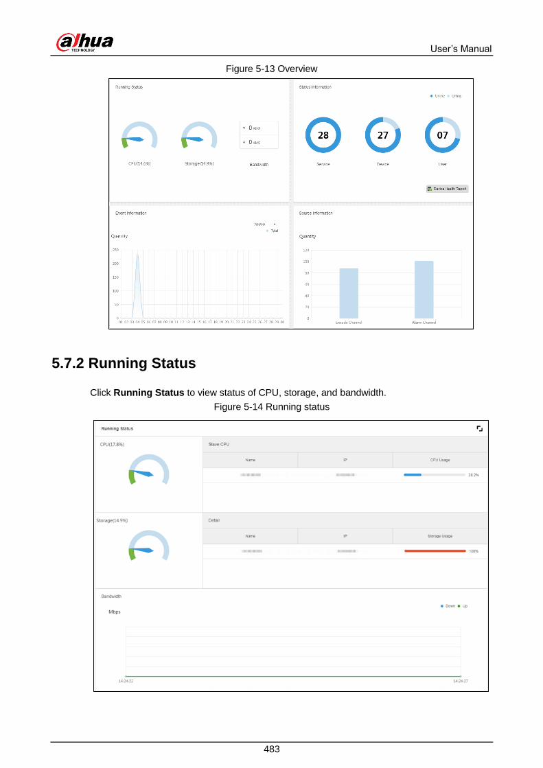
User’s Manual
483
Overview Figure 5-13
5.7.2 Running Status
Click Running Status to view status of CPU, storage, and bandwidth.
Running status Figure 5-14

User’s Manual
484
5.7.3 Status Information
View the status of server, devices, and users.
Service Status Information
Click on the Service Status interface, and then the interface displays service details.
Service status Figure 5-15
Device Status Information
Click on the Web Manager, and then select Overview. Step 1
Click Device Status. Step 2
Real-time device status Figure 5-16
Check device status. Step 3
Click the Real Time tab on the device status information interface to view device
real-time status.
Click the History tab on the device status information interface to view device
history status.

User’s Manual
485
View real-time/history device status Figure 5-17
Click Export to exports device real-time status information (PDF format). Step 4
Click User State and Device Health Report to view details. Step 5
5.7.4 Event Information
View total number of alarm events and processed events by month.

User’s Manual
486
Event information Figure 5-18
5.7.5 Source Information
View the statistics of video channels and alarm channels. Click Source Information or the
icon below to go to the detailed interface.
View video channel details.

User’s Manual
487
Video channel details Figure 5-19
Click the Alarm tab to view the details of alarm channels.

User’s Manual
488
Service Module Introduction Appendix 1
Service Name Service
Name Function Description Port
Protocol
Type
Center
Management
Service
DSS_WEB
Center management service is
to manage each service and
provide accessing port.
HTTPS:
443 TCP
Message Queue
Service DSS_MQ
Message queue service is to
transfer messages between the
platforms.
61616 TCP
DMS
(Device
Management
Service)
DSS_DMS
Device management service is
to register front-end encoder,
receive alarm, transfer alarm
and send out sync time
command.
9200 TCP
MTS
(Media
Transmission
Service )
DSS_MTS
Media transmission service is to
get the audio/video bit stream
from the front-end device and
then transfer these data to the
SS, client and decoder.
9100 TCP
SS
(Storage
Service)
DSS_SS Storage service is to
storage/search/playback record. 9320 TCP
VMS
(Video Matrix
Service)
DSS_VMS
Video matrix service is to login
the the decoder and send out
task to the decoder to output to
the TV wall.
Not fixed,
do not
need to be
mapped to
the outside.
TCP
MGW
(Media Gateway
Service)
DSS_MGW
Media gateway service is to
send out MTS service to the
decoder.
9090 TCP
ARS
(Auto Register
Service)
DSS_ARS
Auto register service is to listen,
login, or get bit streams to send
to MTS.
9500 TCP
PCPS
(ProxyList
control Proxy
Service)
DSS_PCPS
ProxyList control Proxy Service
is to login Hikvision device,
ONVIF device, and then get the
stream and transfer the data to
MTS.
5060
14509
UDP
TCP
ADS
(Alarm Dispatch
Service)
DSS_ADS
Alarm dispatch service is to
send out alarm information to
different objects according to
the plans.
9600 TCP

User’s Manual
489
MCD
(Multi-Control
Device)
DSS_MCD
Deals with alarm devices
access. The MCD service
simulates devices and deals
with access of SDK of alarm
controllers, access control
devices and dynamic
environment monitoring
devices.
30001 TCP
PES
(Power
Environment
Server)
DSS_PES
Deals with access of dynamic
environment monitoring
devices.
11001 TCP
SC
(Switch Center) DSS_SC
Deals with PC client and App
client login as SIP client, and
also forwards the audio-talk
stream.
28001 TCP
OSS
(Object Storage
Service)
DSS_OSS
Deals with storage of face
snapshots and intelligent alarm
pictures.
9901 TCP
PTS
(Picture Transfer
Server)
DSS_PTS Deals with picture transmission 13001 TCP

User’s Manual
490
Cybersecurity Recommendations Appendix 2
Cybersecurity is more than just a buzzword: it’s something that pertains to every device that is
connected to the internet. IP video surveillance is not immune to cyber risks, but taking basic
steps toward protecting and strengthening networks and networked appliances will make them
less susceptible to attacks. Below are some tips and recommendations on how to create a
more secured security system.
Mandatory actions to be taken for basic equipment network security:
1. Use Strong Passwords
Please refer to the following suggestions to set passwords:
The length should not be less than 8 characters;
Include at least two types of characters; character types include upper and lower case
letters, numbers and symbols;
Do not contain the account name or the account name in reverse order;
Do not use continuous characters, such as 123, abc, etc.;
Do not use overlapped characters, such as 111, aaa, etc.;
2. Update Firmware and Client Software in Time
According to the standard procedure in Tech-industry, we recommend to keep your
equipment (such as NVR, DVR, IP camera, etc.) firmware up-to-date to ensure the
system is equipped with the latest security patches and fixes. When the equipment is
connected to the public network, it is recommended to enable the “auto-check for
updates” function to obtain timely information of firmware updates released by the
manufacturer.
We suggest that you download and use the latest version of client software.
"Nice to have" recommendations to improve your equipment network security:
1. Physical Protection
We suggest that you perform physical protection to equipment, especially storage devices.
For example, place the equipment in a special computer room and cabinet, and implement
well-done access control permission and key management to prevent unauthorized
personnel from carrying out physical contacts such as damaging hardware, unauthorized
connection of removable equipment (such as USB flash disk, serial port), etc.
2. Change Passwords Regularly
We suggest that you change passwords regularly to reduce the risk of being guessed or
cracked.
3. Set and Update Passwords Reset Information Timely
The equipment supports password reset function. Please set up related information for
password reset in time, including the end user’s mailbox and password protection
questions. If the information changes, please modify it in time. When setting password
protection questions, it is suggested not to use those that can be easily guessed.
4. Enable Account Lock
The account lock feature is enabled by default, and we recommend you to keep it on to
guarantee the account security. If an attacker attempts to log in with the wrong password
several times, the corresponding account and the source IP address will be locked.

User’s Manual
491
5. Change Default HTTP and Other Service Ports
We suggest you to change default HTTP and other service ports into any set of numbers
between 1024~65535, reducing the risk of outsiders being able to guess which ports you
are using.
6. Enable HTTPS
We suggest you to enable HTTPS, so that you visit Web service through a secure
communication channel.
7. Enable Whitelist
We suggest you to enable whitelist function to prevent everyone, except those with
specified IP addresses, from accessing the system. Therefore, please be sure to add your
computer’s IP address and the accompanying equipment’s IP address to the whitelist.
8. MAC Address Binding
We recommend you to bind the IP and MAC address of the gateway to the equipment,
thus reducing the risk of ARP spoofing.
9. Assign Accounts and Privileges Reasonably
According to business and management requirements, reasonably add users and assign a
minimum set of permissions to them.
10. Disable Unnecessary Services and Choose Secure Modes
If not needed, it is recommended to turn off some services such as SNMP, SMTP, UPnP,
etc., to reduce risks.
If necessary, it is highly recommended that you use safe modes, including but not limited to
the following services:
SNMP: Choose SNMP v3, and set up strong encryption passwords and authentication
passwords.
SMTP: Choose TLS to access mailbox server.
FTP: Choose SFTP, and set up strong passwords.
AP hotspot: Choose WPA2-PSK encryption mode, and set up strong passwords.
11. Audio and Video Encrypted Transmission
If your audio and video data contents are very important or sensitive, we recommend that
you use encrypted transmission function, to reduce the risk of audio and video data being
stolen during transmission.
Reminder: encrypted transmission will cause some loss in transmission efficiency.
12. Secure Auditing
Check online users: we suggest that you check online users regularly to see if the
device is logged in without authorization.
Check equipment log: By viewing the logs, you can know the IP addresses that were
used to log in to your devices and their key operations.
13. Network Log
Due to the limited storage capacity of the equipment, the stored log is limited. If you need
to save the log for a long time, it is recommended that you enable the network log function
to ensure that the critical logs are synchronized to the network log server for tracing.
14. Construct a Safe Network Environment
In order to better ensure the safety of equipment and reduce potential cyber risks, we
recommend:

User’s Manual
492
Disable the port mapping function of the router to avoid direct access to the intranet
devices from external network.
The network should be partitioned and isolated according to the actual network needs.
If there are no communication requirements between two sub networks, it is
suggested to use VLAN, network GAP and other technologies to partition the network,
so as to achieve the network isolation effect.
Establish the 802.1x access authentication system to reduce the risk of unauthorized
access to private networks.
It is recommended that you enable your device's firewall or blacklist and whitelist
feature to reduce the risk that your device might be attacked.

User’s Manual
493
Related Documents


