DSS Pro User ‟s Manual V7.02 Zhejiang Dahua Vision Technology Co., Ltd

Welcome message from author
This document is posted to help you gain knowledge. Please leave a comment to let me know what you think about it! Share it to your friends and learn new things together.
Transcript

DSS Pro
User‟s Manual
V7.02
Zhejiang Dahua Vision Technology Co., Ltd

Cybersecurity Recommendations I
Cybersecurity Recommendations
Mandatory actions to be taken towards cybersecurity
1. Change Passwords and Use Strong Passwords:
The number one reason systems get “hacked” is due to having weak or default passwords. It is
recommended to change default passwords immediately and choose a strong password whenever
possible. A strong password should be made up of at least 8 characters and a combination of special
characters, numbers, and upper and lower case letters.
2. Update Firmware
As is standard procedure in the tech-industry, we recommend keeping NVR, DVR, and IP camera
firmware up-to-date to ensure the system is current with the latest security patches and fixes.
“Nice to have” recommendations to improve your network security
1. Change Passwords Regularly
Regularly change the credentials to your devices to help ensure that only authorized users are able to
access the system.
2. Change Default HTTP and TCP Ports:
● Change default HTTP and TCP ports for systems. These are the two ports used to communicate and
to view video feeds remotely.
● These ports can be changed to any set of numbers between 1025-65535. Avoiding the default ports
reduces the risk of outsiders being able to guess which ports you are using.
3. Enable HTTPS/SSL:
Set up an SSL Certificate to enable HTTPS. This will encrypt all communication between your devices
and recorder.
4. Enable IP Filter:
Enabling your IP filter will prevent everyone, except those with specified IP addresses, from accessing
the system.
5. Change ONVIF Password:
On older IP Camera firmware, the ONVIF password does not change when you change the system‟s
credentials. You will need to either update the camera‟s firmware to the latest revision or manually
change the ONVIF password.
6. Forward Only Ports You Need:
Only forward the HTTP and TCP ports that you need to use. Do not forward a huge range of
numbers to the device. Do not DMZ the device's IP address.
You do not need to forward any ports for individual cameras if they are all connected to a recorder
on site; just the NVR is needed.
7. Disable Auto-Login on DSS:
Those using DSS to view their system and on a computer that is used by multiple people should disable
auto-login. This adds a layer of security to prevent users without the appropriate credentials from
accessing the system.
8. Use a Different Username and Password for DSS:

Cybersecurity Recommendations II
In the event that your social media, bank, email, etc. account is compromised, you would not want
someone collecting those passwords and trying them out on your video surveillance system. Using a
different username and password for your security system will make it more difficult for someone to
guess their way into your system.
9. Limit Features of Guest Accounts:
If your system is set up for multiple users, ensure that each user only has rights to features and functions
they need to use to perform their job.
10. UPnP:
● UPnP will automatically try to forward ports in your router or modem. Normally this would be a good
thing. However, if your system automatically forwards the ports and you leave the credentials defaulted,
you may end up with unwanted visitors.
● If you manually forwarded the HTTP and TCP ports in your router/modem, this feature should be
turned off regardless. Disabling UPnP is recommended when the function is not used in real
applications.
11. SNMP:
Disable SNMP if you are not using it. If you are using SNMP, you should do so only temporarily, for
tracing and testing purposes only.
12. Multicast:
Multicast is used to share video streams between two recorders. Currently there are no known issues
involving Multicast, but if you are not using this feature, deactivation can enhance your network security.
13. Check the Log:
If you suspect that someone has gained unauthorized access to your system, you can check the system
log. The system log will show you which IP addresses were used to login to your system and what was
accessed.
14. Physically Lock Down the Device:
Ideally, you want to prevent any unauthorized physical access to your system. The best way to achieve
this is to install the recorder in a lockbox, locking server rack, or in a room that is behind a lock and key.
15. Connect IP Cameras to the PoE Ports on the Back of an NVR:
Cameras connected to the PoE ports on the back of an NVR are isolated from the outside world and
cannot be accessed directly.
16. Isolate NVR and IP Camera Network
The network your NVR and IP camera resides on should not be the same network as your public
computer network. This will prevent any visitors or unwanted guests from getting access to the same
network the security system needs in order to function properly.

Regulatory Information III
Regulatory Information
FCC Information
CAUTION
Changes or modifications not expressly approved by the party responsible for compliance
could void the user's authority to operate the equipment.
FCC conditions:
This device complies with part 15 of the FCC Rules. Operation is subject to the following two
conditions:
This device may not cause harmful interference.
This device must accept any interference received, including interference that may cause
undesired operation.
FCC compliance:
This equipment has been tested and found to comply with the limits for a digital device,
pursuant to part 15 of the FCC Rules. This equipment generate, uses and can radiate radio
frequency energy and, if not installed and used in accordance with the guide, may cause
harmful interference to radio communication.
For class A device, these limits are designed to provide reasonable protection against harmful
interference in a commercial environment. Operation of this equipment in a residential area
is likely to cause harmful interference in which case the user will be required to correct the
interference at his own expense.
For class B device, these limits are designed to provide reasonable protection against harmful
interference in a residential installation. However, there is no guarantee that interference
will not occur in a particular installation. If this equipment does cause harmful interference
to radio or television reception, which can be determined by turning the equipment off and
on, the user is encouraged to try to correct the interference by one or more of the following
measures:
Reorient or relocate the receiving antenna.
Increase the separation between the equipment and receiver.
Connect the equipment into an outlet on a circuit different from that to which the
receiver is connected.
Consult the dealer or an experienced radio/TV technician for help.

Foreword IV
Foreword
General
This user‟s manual (hereinafter referred to be "the Manual") introduces the functions and
operations of the DSS general surveillance management center (hereinafter referred to be
"the Device" or "the System") and client operations.
Safety Instructions
The following categorized signal words with defined meaning might appear in the Manual.
Signal Words Meaning
DANGER
Indicates a high potential hazard which, if not avoided, will result in
death or serious injury.
WARNING
Indicates a medium or low potential hazard which, if not avoided,
could result in slight or moderate injury.
CAUTION
Indicates a potential risk which, if not avoided, could result in
property damage, data loss, lower performance, or unpredictable
result.
TIPS Provides methods to help you solve a problem or save you time.
NOTE Provides additional information as the emphasis and supplement to
the text.
Privacy Protection Notice
As the device user or data controller, you might collect personal data of others' such as face,
fingerprints, car plate number, Email address, phone number, GPS and so on. You need to be
in compliance with the local privacy protection laws and regulations to protect the legitimate
rights and interests of other people by implementing measures including but not limited to:
providing clear and visible identification to inform data subject the existence of surveillance
area and providing related contact.

Foreword V
Revision History
No. Version Revision Content Release Time
1 V7.02 Optimizes outlines and contents Sept 2018
About the Manual
The Manual is for reference only. If there is inconsistency between the Manual and the actual
product, the actual product shall prevail.
We are not liable for any loss caused by the operations that do not comply with the Manual.
The Manual would be updated according to the latest laws and regulations of related regions.
For detailed information, see the paper manual, CD-ROM, QR code or our official website. If
there is inconsistency between paper manual and the electronic version, the electronic version
shall prevail.
All the designs and software are subject to change without prior written notice. The product
updates might cause some differences between the actual product and the Manual. Please
contact the customer service for the latest program and supplementary documentation.
There still might be deviation in technical data, functions and operations description, or errors in
print. If there is any doubt or dispute, please refer to our final explanation.
Upgrade the reader software or try other mainstream reader software if the Guide (in PDF
format) cannot be opened.
All trademarks, registered trademarks and the company names in the Manual are the
properties of their respective owners.
Please visit our website, contact the supplier or customer service if there is any problem
occurred when using the device.
If there is any uncertainty or controversy, please refer to our final explanation.

Foreword VI
Important Safeguards and Warnings
This Chapter describes the contents covering proper handling of the Device, hazard prevention,
and prevention of property damage. Read these contents carefully before using the Device,
comply with them when using, and keep it well for future reference.
Operation Requirement
Do not place or install the Device in a place exposed to sunlight or near the heat source.
Keep the Device away from dampness, dust or soot.
Keep the Device installed horizontally on the stable place to prevent it from falling.
Do not drop or splash liquid onto the Device, and make sure there is no object filled with
liquid on the Device to prevent liquid from flowing into the Device.
Install the Device in a well-ventilated place, and do not block the ventilation of the Device.
Operate the device within the rated range of power input and output.
Do not dissemble the Device.
Transport, use and store the Device under the allowed humidity and temperature
conditions.
Electrical Safety
Improper battery use might result in fire, explosion, or inflammation.
When replacing battery, make sure the same model is used.
Use the recommended power cables in the region and conform to the rated power
specification.
Use the power adapter provided with the Device; otherwise, it might result in people injury
and device damage.
The power source shall conform to the requirement of the Safety Extra Low Voltage (SELV)
standard, and supply power with rated voltage which conforms to Limited power Source
requirement according to IEC60950-1. Please note that the power supply requirement is
subject to the device label.
Connect the device (I-type structure) to the power socket with protective earthing.
The appliance coupler is a disconnection device. When using the coupler, keep the angle
for easy operation.

Overview VII
Table of Contents
Cybersecurity Recommendations ..................................................................................................... I
Regulatory Information ........................................................................................................................... III
Foreword .................................................................................................................................................. IV
1 Overview ................................................................................................................................................. 1
1.1 Introduction ................................................................................................................................... 1
1.2 Highlights ...................................................................................................................................... 1
2 Business Flow Chart ............................................................................................................................. 2
3 Installation and Deployment ................................................................................................................ 3
3.1 Server Config Requirement .......................................................................................................... 3
3.2 DSS Master Server Deployment ................................................................................................... 3
3.2.1 Master Server Installation ................................................................................................... 3
3.2.2 Uninstallation ...................................................................................................................... 7
3.3 Slave Server Deployment ............................................................................................................. 8
3.3.1 Slave Server Installation ..................................................................................................... 8
3.3.2 Configuring Slave Server .................................................................................................. 12
3.3.3 Enabling Slave Server ...................................................................................................... 13
3.4 Configuring System ..................................................................................................................... 13
3.5 Modifying Service Port ................................................................................................................ 15
3.6 Configuring LAN/WAN ................................................................................................................ 16
3.6.1 Configuring Router ............................................................................................................ 16
3.6.2 Configuring DSS Platform ................................................................................................ 17
4 Manager Operations ............................................................................................................................ 19
4.1 Logging in Management End ...................................................................................................... 19
4.2 Authorization ............................................................................................................................... 20
4.2.1 License Introduction.......................................................................................................... 20
4.2.2 Applying for License.......................................................................................................... 21
4.2.3 Loading License ................................................................................................................ 22
4.3 System Settings .......................................................................................................................... 24
4.3.1 Setting System Parameters .............................................................................................. 24
4.3.2 FTP ................................................................................................................................... 26
4.3.3 Setting Mail Server ........................................................................................................... 27
4.4 Adding Organization .................................................................................................................... 28
4.5 Adding Role and User ................................................................................................................. 30
4.5.1 Adding User Role .............................................................................................................. 30
4.5.2 Adding User ...................................................................................................................... 31
4.5.3 Setting Domain User......................................................................................................... 33
4.6 Adding Device ............................................................................................................................. 37
4.6.1 Adding Device Manually ................................................................................................... 37
4.6.2 Searching Added Device .................................................................................................. 40
4.6.3 Editing Device ................................................................................................................... 41
4.6.4 Binding Resource ............................................................................................................. 46

Overview VIII
4.7 Configuring Record Plan ............................................................................................................. 48
4.7.1 Configuring Storage Disk .................................................................................................. 48
4.7.2 Setting Disk Group Quota ................................................................................................. 50
4.7.3 Adding General Plan ......................................................................................................... 52
4.7.4 Adding Backup Record Plan ............................................................................................. 54
4.7.5 Adding Time Template ...................................................................................................... 56
4.8 Configuring Event ....................................................................................................................... 58
4.8.1 Configuring Alarm Source ................................................................................................. 58
4.8.2 Adding Alarm Scheme ...................................................................................................... 59
4.9 Configuring Average Speed ........................................................................................................ 68
4.9.1 Configuring Location ......................................................................................................... 68
4.9.2 Configuring Location Interval ............................................................................................ 70
4.10 Configuring Map ........................................................................................................................ 73
4.10.1 Editing Google Map ........................................................................................................ 73
4.10.2 Adding Hot Zone ............................................................................................................. 75
4.10.3 Marking Device ............................................................................................................... 78
4.11 Adding Video Wall ..................................................................................................................... 79
4.12 Configuring Face Recognition .................................................................................................. 81
4.12.1 Creating Face Database ................................................................................................. 81
4.12.2 Arm Config ...................................................................................................................... 87
4.13 Adding Vehicle Blacklist ............................................................................................................ 90
4.14 Adding Store .............................................................................................................................. 92
4.15 System Maintenance ................................................................................................................ 96
4.15.1 Service Management ...................................................................................................... 96
4.15.2 Backup and Restore ....................................................................................................... 97
4.15.3 Log ................................................................................................................................ 103
4.15.4 System Dashboard ....................................................................................................... 104
5 Client Functions ................................................................................................................................. 111
5.1 Installation and Login of the Client ............................................................................................. 111
5.1.1 PC Requirements ............................................................................................................ 111
5.1.2 Download and Installation ............................................................................................... 111
5.1.3 Login Client ......................................................................................................................114
5.2 Local Configuration ....................................................................................................................116
5.3 Video Preview ........................................................................................................................... 122
5.3.1 Preparations ................................................................................................................... 122
5.3.2 Real-Time Preview ......................................................................................................... 123
5.3.3 PTZ ................................................................................................................................. 128
5.3.4 Smart Track .................................................................................................................... 134
5.3.5 View Tour ........................................................................................................................ 137
5.3.6 Region of Interest (RoI) .................................................................................................. 139
5.4 Record ....................................................................................................................................... 140
5.4.1 Preparations ................................................................................................................... 140
5.4.2 Recording when Previewing ........................................................................................... 141
5.4.3 Playback ......................................................................................................................... 142
5.4.4 Search Thumbnail ........................................................................................................... 147
5.4.5 Download ........................................................................................................................ 151
5.5 Event Center ............................................................................................................................. 155

Overview IX
5.5.1 Preparations ................................................................................................................... 155
5.5.2 Configuring Alarm Parameters ....................................................................................... 156
5.5.3 Searching and then Processing Real-Time Alarm ......................................................... 157
5.6 Video Wall ................................................................................................................................. 162
5.6.1 Preparations ................................................................................................................... 162
5.6.2 Output to the Wall ........................................................................................................... 162
5.6.3 Video Wall Plan ............................................................................................................... 164
5.7 Emap ......................................................................................................................................... 167
5.7.1 Preparations ................................................................................................................... 167
5.7.2 Open Emap on the Real-Time Preview .......................................................................... 168
5.7.3 Viewing Map ................................................................................................................... 170
5.7.4 Alarm Flashing on the Map ............................................................................................. 172
5.8 People Counting........................................................................................................................ 174
5.8.1 Preparations ................................................................................................................... 174
5.8.2 People Counting Report ................................................................................................. 175
5.8.3 Viewing People Counting Statistics on Live View Interface ........................................... 176
5.8.4 Heatmap ......................................................................................................................... 177
5.9 Human Face Recognition ......................................................................................................... 178
5.9.1 Preparations ................................................................................................................... 178
5.9.2 Real-Time Human Face Video ....................................................................................... 179
5.9.3 Searching Snapshot Images .......................................................................................... 181
5.9.4 Searching on the Snapshot Database............................................................................ 182
5.9.5 Statistics Report .............................................................................................................. 184
5.10 Road Monitoring Applications ................................................................................................. 186
5.10.1 Preparations ................................................................................................................. 186
5.10.2 Road Monitor ................................................................................................................ 186
5.10.3 Searching Passed Vehicle ............................................................................................ 188
5.10.4 Vehicle Track ................................................................................................................ 191
5.10.5 Monitor Place ................................................................................................................ 194
5.11 Traffic ....................................................................................................................................... 197
5.11.1 Preparations .................................................................................................................. 197
5.11.2 Searching Violation Information .................................................................................... 198
5.11.3 Search Vehicle Flows.................................................................................................... 200
5.11.4 Searching Speed during a Specified Range ................................................................ 202
5.12 Business Intelligence .............................................................................................................. 204
5.12.1 Preparations ................................................................................................................. 205
5.12.2 Business Report ........................................................................................................... 205
5.12.3 People Flows Analysis .................................................................................................. 207
5.12.4 POS Data ...................................................................................................................... 209
5.12.5 Structured Data ..............................................................................................................211
5.13 Time Synchronization .............................................................................................................. 213
5.13.1 Device Time Synchronization ....................................................................................... 213
5.13.2 Time Synchronization on the Client .............................................................................. 214
Service Module Introduction .......................................................................................... 217 Appendix 1

Overview 1
1 Overview
1.1 Introduction
DSS Pro is a type of video surveillance software which is flexible, easily-extendable,
highly-reliable and more professional. DSS Pro is able to meet the requirements of large and
medium-sized projects via distributed extension performance. In addition to basic video
surveillance business, DSS Pro supports a series of AI functions, such as face recognition,
license plate recognition and people counting etc. it can also expand functions like
transportation and business analysis via value-added modules. These rich functions enable
DSS Pro to be widely used in chain supermarket, casino, safe town, road traffic, medium and
large-sized campus surveillance and some other scenarios.
1.2 Highlights
Easily extendable
Supports extension system performance.
Supports DSS Pro extension via Add-ons.
More professional
Supports system operation and maintenance, easily acquire service, system, device,
time and some other system info.
Separate Web management end, makes management more convenient and
professional.
Supports face recognition, plate recognition, people counting and other AI functions,
retail and transportation functions, makes DSS Pro more powerful.
Highly reliable
Supports dual hot standby, makes DSS Pro system more stable.
Supports system data auto backup and manual backup, reduce loss caused by
system crash.
More open
Supports standard Onvif protocol connecting to third-party device.
Open SDK, the third party platform can be connected via SDK.

Business Flow Chart 2
2 Business Flow Chart
In the business flow chart, shading means config item, shading means the exact
application of business in the client.
The overall flow chart is shown in Figure 2-1.
Figure 2-1

Installation and Deployment 3
3 Installation and Deployment
DSS platform supports both single server deployment and master/slave distributed
deployment.
3.1 Server Config Requirement
Please refer to Table 3-1 for the requirements of server config.
Table 3-1
Parameter Hardware Requirement
Recommended
config
CPU:E5-2640 [email protected] 2.60GHz 8core
RAM:16GB
Network card:1Gps
Hard drive type:HDD 1TB
DSS installation directory space:Over 500G
Minimum config
CPU:E3-1220 v5 @3.00GHz 3.00GHz 4core
RAM:8GB
Network card:1Gps
Hard drive type:HDD 1TB
DSS installation directory space:Over 500G
3.2 DSS Master Server Deployment
3.2.1 Master Server Installation
Double click and enter installation mode. Step 1
The system will display the interface. See Figure 3-1.
Program name includes version number and program data, please confirm it before
installation.

Installation and Deployment 4
Figure 3-1
Click “Agreement Protocol”, read and accept agreement protocol, select “I have read Step 2
and agree the agreement”, click “Next”.
The system displays the interface. See Figure 3-2.
Figure 3-2
Select installation mode as “Master”, make sure if it supports dual hot standby, click Step 3
“Next‟.
Master means master mode; Slave means slave mode; HA means it supports dual hot
standby.

Installation and Deployment 5
The system displays the interface. See Figure 3-3.
Figure 3-3
Select installation path, it supports default installation path, you can click “Browse” to Step 4
customize installation directory.
After selecting installation directory, the system displays need space and free space of
installation.
If “Install Now” button is gray, please check if installation directory is correct, or if the
available space of installation directory is bigger than the space needed by system.
Click “Install Now” Step 5
The system displays the interface. See Figure 3-4. The installation process needs
about 3 to 5 minutes, please wait patiently. The interface is shown in Figure 3-5 after
installation is completed.

Installation and Deployment 6
Figure 3-4
Figure 3-5
Click “Start Now” and it enables service immediately. Step 6
The system displays the interface. See Figure 3-6.

Installation and Deployment 7
Figure 3-6
3.2.2 Uninstallation
Select “Start > All Programs”, unfold DSS Pro folder, click “DSS Pro Uninstall”. Step 1
The system displays the interface. See Figure 3-7.
Figure 3-7
Click „Continue”. Step 2

Installation and Deployment 8
The system displays uninstallation progress; the system will display the interface which
is shown in Figure 3-8 after uninstallation is completed.
Figure 3-8
Click “OK” to complete uninstallation. Step 3
3.3 Slave Server Deployment
Please skip the chapter if it only needs to deploy a single server.
3.3.1 Slave Server Installation
Double click installation program and enter installation mode. Step 1
The system displays the interface. See Figure 3-9.
The program name includes version number and program data, please confirm it
before installation.

Installation and Deployment 9
Figure 3-9
Click “Agreement Protocol”, read and accept agreement protocol, select “I have read Step 2
and agree the agreement”, click “Next”.
The system displays the interface. See Figure 3-10.
Figure 3-10
Select installation mode as “Slave”, click “Next”. Step 3
The system displays the interface. See Figure 3-11.

Installation and Deployment 10
Figure 3-11
Select installation path, supports default installation path, click “Browse” to customize Step 4
installation directory.
After selecting directory, the system displays space needed for installation and
available space for selected path.
If “Install Now” button becomes gray, please check if installation directory is correct or
available space of installation directory is bigger than space needed by system.
Click “Install Now”. Step 5
The system displays the interface. See Figure 3-12. The installation process needs
about 3 to 5 minutes, please wait patiently. The interface is shown in Figure 3-13 after
installation is completed.

Installation and Deployment 11
Figure 3-12
Figure 3-13
Click “Start Now” to enable server immediately. Step 6
The system displays the interface. See Figure 3-14.

Installation and Deployment 12
Figure 3-14
3.3.2 Configuring Slave Server
For slave server, it only needs to configure the master server IP and port, and then it can be
registered onto the master server.
Double click on the slave server. Step 1
The system displays the interface. See Figure 3-14.
Click on the top right corner of the interface. Step 2
The system displays the interface. See Figure 3-15.

Installation and Deployment 13
Figure 3-15
Set “Center IP”, “Local IP” and each port number, click “OK”. Step 3
The system auto detects if master server IP and port are valid, it will restart the service
of slave server if it is valid, DSS Server will be loaded again; it will pop out the prompt
box shown in Figure 3-16 if info detection fails. It needs to reset it.
Figure 3-16
3.3.3 Enabling Slave Server
It can enable server from the platform management end and check the status of each server,
please refer to “4.15.1 Server Management” for more details.
3.4 Configuring System
It is to introduce the operations of config tool.

Installation and Deployment 14
Figure 3-17
Table 3-2
SN Function Note
1 Service
Management
Service management, it supports following three types of operation:
Click to restart all services.
Click to stop all services.
Click to refresh services.
2 Language
The system supports two languages which are Chinese and English. It
supports language switch by click the icon. It needs to restart to make config
tool valid after switching languages.
3 Setting
It is to set CMS IP as the IP address of server which installs DSS. If it is in the
LAN/WAN environment, then it needs to configure mapping address as WAN
IP address.
4 About Click the icon to check software version and release date.
5 Minimize Click the icon and it minimizes the config tool interface.
6 Disable Disable config tool.
Installation and Deployment 15
SN Function Note
7
Service
Status
Display
It is to display service total status, including:
: Service abnormity for the server.
: All the services of the server run normally.
8 Service
Display
It is to display each service and service status. Click to modify service
port number, the system will restart service automatically after modification.
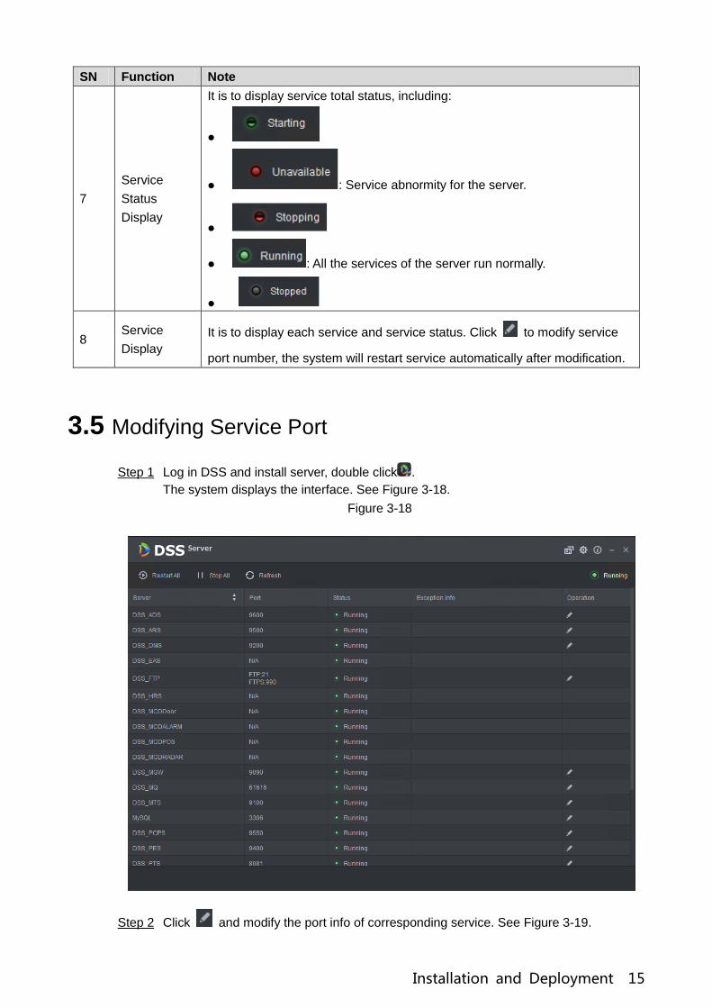
3.5 Modifying Service Port
Log in DSS and install server, double click . Step 1
The system displays the interface. See Figure 3-18.
Figure 3-18
Click and modify the port info of corresponding service. See Figure 3-19. Step 2

Installation and Deployment 16
If there is LAN/WAN config, then LAN/WAN port are modified as the value customized
by users.
“DSS_PTS” service default port is “8081”, which can be often occupied; it is
recommended to modify the port.
The system will prompt when the port is occupied, please modify port in time
according to the prompt.
Figure 3-19
Click “OK” to save config. Step 3
The system will restart service after it is successfully modified.
3.6 Configuring LAN/WAN
Now the DSS Server config system does not distinguish between LAN and WAN port of service,
port config option is uniform, LAN and WAN port are consistent.
3.6.1 Configuring Router
It is recommended to do DMZ mapping, it can do port mapping if it is not allowed by the
environment. The ports which need to be opened are 9500、9200、21、990、9090、61616、
9100、3306、9550、9400、80、5080 and so on. Please refer to “Appendix 1 Service Module
Introduction” for more details about port. If there is port being occupied by other mapping, for

Installation and Deployment 17
example, 80 port has been occupied and it needs to be modified as 81, then it needs to modify
port by referring to “3.5 Modifying Service Port”, and then it can add mapping rule onto the
router.
3.6.2 Configuring DSS Platform
Log in DSS and install server, double click . Step 1
The system displays the interface. See Figure 3-20.
Figure 3-20
Click the on the top right corner. Step 2
The system displays the interface. See Figure 3-21.

Installation and Deployment 18
Figure 3-21
Set “Mapping IP” as WAN address, click “OK”. Step 3
The system pops out the dialog box. See Figure 3-22.
Figure 3-22
Click “OK” and the system restarts service. Step 4

Manager Operations 19
4 Manager Operations
It needs to use Internet Explorer 9 or higher version browser to log in DSS PROFESSIONAL
platform, or you can use Google Chrome and Firefox as well.
4.1 Logging in Management End
It can log in the management end of platform server via browser, and realize remote config of
relevant business by administrator.
Enter platform IP address in the browser, press【Enter】button. Step 1
The system displays the login interface. See Figure 4-1.
Figure 4-1
Enter username and password, click “Login”. Step 2
The default username is system.
The system will pop out the interface of modifying password if it is the first time to
log in system. It can continue to log in system after the password is modified in
time.
Please add the platform IP address into the trusted sites of browser if it is your first
time to log in DSS management end.
It will display the homepage after login. See Figure 4-2.

Manager Operations 20
Figure 4-2
Place the mouse on the username of top right corner, and then you can modify password
or log out current user.
The shortcut access of general modules is displayed on the top of interface, click on
the homepage to present all the modules and open new modules.
Overview: It displays the online/offline status of device, user and service, and the usage
proportion of hard drive.
Authorization: Check authorization details, purchase authorization document step by step
according to requirements. Please refer to “4.2 Authorization” for more operation details.
Help: Check user operation manual, FAQ file and so on.
4.2 Authorization
4.2.1 License Introduction
Please refer to Table 4-1 for description of probation period, there is no limit for modules and
channels (such as alarm input and output) that are not in the table.
The probation period only lasts 90 days, it is recommended to purchase License. It fails to use
„Device”, “Event”, “Storage” or “TV Wall” when you log in DSS management without purchasing
License after 90-day probation period, and it cannot log in client or mobile APP.
Table 4-1
Function Performance
Channel Video (Encoding) 32 channels
Face Recognition 2 channels
ANPR 2 channels
POS 2 channels
Module Transportation 90 days

Manager Operations 21
Function Performance
Business Intelligence 90 days
4.2.2 Applying for License
Applying for License includes first application and second application when upgrading License.
The quantity of all the authorized channel starts from 0 for the first application, the initial status
of module authorization is “probation”. The authorization status becomes “Purchased” if it is
bought again. The purchase quantity of second purchase means the quantity which needs to
be added. If you want to increase to 10 channels after you already own 5 channels, then you
only need to purchase another 5 channels.
Acquire authorization request file. Step 1
Log in DSS management end. 1)
Click “Step 1” on the “Homepage” interface, which is shown in Figure 4-3. 2)
The system displays “Upgrade” interface. See Figure 4-4.
Figure 4-3

Manager Operations 22
Figure 4-4
Enter channel number and select module according to actual purchase. 3)
Click “Export”, generate zip compression package and save it under the default 4)
download path of the browser.
It supports to open, save or save as the export file on the interface after export is
completed.
Send authorization application file to sales, which is used to acquire authorization file. Step 2
4.2.3 Loading License
Please make sure you have made application and acquired License file before loading License.
Log in DSS management end. Step 1
Click “Step 3” on the “Homepage” interface, which is shown in Figure 4-5. Step 2
The system displays “Upgrade” interface. See Figure 4-6.

Manager Operations 23
Figure 4-5
Figure 4-6
Click “Browse” and select the uploaded License file. Step 3
Click “Import” and complete License loading. Step 4
The system prompts that authorization information has changed after loading, and then
the program starts again.
Log in DSS management end again, click “License Details” on the “Homepage” Step 5
interface, and check License.

Manager Operations 24
Click “Upgrade Now” and skip to “Upgrade” interface, then you can export authorization
application file.
Figure 4-7
4.3 System Settings
4.3.1 Setting System Parameters
It needs to configure system parameters when it is first time to log in DSS system, which is to
make sure that the system runs normally.
Click , select “System Settings” in the interface of “New Tab”. Step 1
The system displays the interface. See Figure 4-8.

Manager Operations 25
Figure 4-8
Table 4-2
Parameter Note
Message
Storage
Time
Setup
Log Sets longest keep time of log, it is 30 days by default.
Alarm info Sets the longest keep time of alarm info, it is 30 days by default.
GPS info Sets the longest keep time of GPS info, it is 30 days by default.
POS Sets the longest keep time of POS info, it is 30 days by default.
Heatmap Sets the longest keep time of heat map info; it is 30 days by
default.
FTP
LAN path The FTP server LAN path where file is stored.
WAN path The FTP server Internet path where file is stored.
Username/
password Username and password used to log in FTP server.
Time Sync
Enable Check it to enable the function of time sync.
Start time Sets start time of time sync.
Sync
Interval
The time of server shall prevail; synchronize the time of device
and server.
It is 2 hours by default, the system is based on the server time
every 2 hours, and then it is to synchronize the time of both
device and server.
NOTE
The time between device and server is synchronized via SDK.
Immediately Click the button to start time sync immediately.

Manager Operations 26
Parameter Note
Mail Server -
It is to set mail server IP, port, encryption type,
username/password, sender, test recipient etc.
It can select to send email to users when the administrator
configures the alarm linkage and the client handles the alarm. At
this moment, it needs to configure mail server first.
Activity
Directory - Set domain info.
HTTPS - Enable HTTPS security verification.
POS End - After setting POS end mark, it will display on the location of POS
receipts end.
Picture
Storage
Setup
Picture
storage time Sets the storage time of the picture, unit: day.
Min
Capacity
Configure corresponding parameters. Step 2
Click „Save”. Step 3
4.3.2 FTP
4.3.2.1 Use
It is to enable FTP in the DSS server, which is mainly used to upload alarm capture to DSS
platform. It can use built-in FTP of DSS system (Fail to support IP address modification), it can
also configure the FTP server which is set up by users themselves.
4.3.2.2 Configuration Method
Click , select “System” in the interface of “New Tab”. Step 1
Click “FTP” and set FTP address, username and password. Step 2
The interface is displayed. See Figure 4-9.

Manager Operations 27
Figure 4-9
NOTE
The item with * has to be filled in, the standard format of FTP address is ftps://x.x.x.x,
the system‟s own FTP address is the IP address of DSS server; both username and
password are dss/dss by default.
Click “Save” to save config. Step 3
You can use relevant tools to visit FTP address.
4.3.3 Setting Mail Server
4.3.3.1 Application Scenarios
It can select to send mail to user when the administrator is configuring alarm linkage and client
handling alarm, at this moment, it needs to configure mail server first.
4.3.3.2 Config Method
Click and select “System” on the interface of “New Tab”. Step 1
Select the tab of “Mail Server”, check “Enable” to enable mail config. See Figure 4-10. Step 2

Manager Operations 28
Figure 4-10
Select the type of mail server in the drop-down box. See Figure 4-11. Step 3
Figure 4-11
It is to set mail server IP, port, encryption type, username/password, sender and test Step 4
recipient etc.
Click “Mail Test” to test if the config of mail server is valid. Test prompt will be received if Step 5
the test is successful, and the test account will receive corresponding email.
Click after the test is successful, and then it can save config info. Step 6
4.4 Adding Organization
Adding organizations is to deploy the hierarchy of organization or device, which is to make it
easy to manage. It doesn‟t have to add organizations, the added users or devices are classified
to the default organization.
The default first level organization of the system is “Root”, the newly-added organization is
displayed at the next level of “root”.

Manager Operations 29
Steps
Click and select “Organization” on the interface of “New Tab”. Step 1
The system displays the interface of organization. See Figure 4-12
Figure 4-12
Select root organization, click “Add”. Step 2
It is to add new organizations under the root organization. See Figure 4-13.
Figure 4-13
Enter organization name, press【Enter】button. Step 3

Manager Operations 30
Operations
Move device: Select the device under the root organization, click , select “New
Organization 1”, click “OK”.
Edit: Click the next to the organization and modify the organization name.
Delete: Select organization, click to delete organization.
4.5 Adding Role and User
4.5.1 Adding User Role
You can create user role and add user. The created user can log in both admin and client.
Different user roles decide users to have different operation permissions.
The operation permission of user role includes device permission, management menu
permission and operation menu permission. First it needs to grant permissions to these
operations and then it can implement corresponding operations.
Click and select “User” on the interface of “New Tab‟. Step 1
The system displays the interface of user. See Figure 4-14.
Figure 4-14
Click „Add” under the “Role” tab. Step 2
The system pops out the interface of “Add Role”.
Enter “Role Name”. Step 3

Manager Operations 31
If it selects “Copy from” next to the “Role Name” and select some role in the drop-down
Box, then it can copy the config info into the selected roles and realize quick config.
Select “Device Permission” and “Operation Permission”. Step 4
The system will display the interface. See Figure 4-15.
Figure 4-15
Note
If it fails to select corresponding device permission or menu permission, then the users
under the role has no corresponding device or menu operation permission.
Click “OK” to add the role. Step 5
4.5.2 Adding User
You can add the user of the role if you have added the user role.
Steps
Click “User” tab. Step 1
The system displays the interface. See Figure 4-16.

Manager Operations 32
Figure 4-16
Click „Add”. Step 2
The system will pop out the interface of “Adding User”.

Manager Operations 33
Figure 4-17
Configure user info, select role below, and it will display device permission and Step 3
operation permission of corresponding role on the right.
NOTE
The user has no “Device Permission” or “Operation Permission” if it fails to select
“Role”.
You can select several roles at the same time.
Click “OK” to add the user. Step 4
Operations
Click to freeze user, the user which logs in the client will quit.
Click to modify user info except username and password.
Click to delete user.
4.5.3 Setting Domain User
The setting in this chapter is optional, please select if it is to set domain user according to the
actual situation.

Manager Operations 34
4.5.3.1 Application Scenario
For the companies with domain information and want to use domain users as system login
users, using domain user import can improve the convenience of project deployment.
4.5.3.2 Setting Domain Info
Click and select “System” on the interface of “New Tab”. Step 1
Click the tab of “Active Directory” and configure domain info. See Figure 4-18. Step 2
Figure 4-18
After setting domain info, click “Get DN” and it will acquire basic DN info automatically. Step 3
After getting DN info, click “Test” to test if domain info is available. Step 4
Click “Save” to save config. Step 5
It can import domain user on the interface of “User” after it prompted successfully.
Please refer to the next chapter for more operation details.
4.5.3.3 Importing Domain User
Click and select “User” on the interface of “New Tab”. Step 1
Select “User” tab, click “Import Domain User” on the right of the interface. Step 2
The system will display the interface of “Import Domain User”. See Figure 4-19.

Manager Operations 35
Figure 4-19
Select the users which need to be imported from the acquired domain users. Step 3
It supports searching users by entering key words in the search box.
Click “Next”. Step 4
The system displays the interface of “Import Domain User”. See Figure 4-20.

Manager Operations 36
Figure 4-20
Select role for domain user, it displays corresponding device info and function Step 5
permission info on the right of the interface, click “OK” after it is confirmed.
Make sure domain user has been successfully imported in “User Info”. See Figure 4-21.
Figure 4-21
4.5.3.4 Logging in Domain User
It can use domain user to log in client.
Select “Domain User” in the drop-down box of “User Type” on the client login interface. Step 1

Manager Operations 37
See Figure 4-22.
Figure 4-22
Enter domain username, password, server IP, port and other info, click “Login”. Step 2
The interface and function are the same as login via general user after it logged in
successfully, which is not going to be repeated here.
4.6 Adding Device
It can add different types of devices according to different business requirements.
4.6.1 Adding Device Manually
Click and select “Device” on the interface of “New Tab”. Step 1
The system will display the interface of “Device”. See Figure 4-23.

Manager Operations 38
Figure 4-23
Click “Add”. Step 2
The interface is shown in Figure 4-24.

Manager Operations 39
Figure 4-24
Select “Protocol”, “Manufacturer”, “Add Type”, “Device Category”, “Organization”, Step 3
“Video Server”, input “IP Address”, “Device Port” and “Username/Password” etc.
NOTE
Select different “Protocol”, it will configure different parameters, please refer to the
interface for more details.
When “Add Type” selects “IP Address”, it enters device IP address.
When “Add type” selects “Auto Register”, it enters device auto register ID. It can
only add encoder via auto register, the ID of auto register has to be in accordance
with the registered ID configured at encoder.
When “Add Type” selects “Domain Name”, the options are from configured domain
during deployment.
Click “Add”. Step 4
The interface is shown in Figure 4-25.

Manager Operations 40
Figure 4-25
Select “Device Type” and enter “Device Name” “Alarm input/output channel” and so on. Step 5
Click “OK”. Step 6
Please click “Continue to add” if it continues to add device.
4.6.2 Searching Added Device
Channels on the LAN with the platform server can be added using the automatic search
function.
Click and select „device” on the interface of “New Tab”. Step 1
Click “Search Again” above the “device” interface. Step 2
NOTE
Click “Network Segment Config” to configure IP segment again, click “Search again” to
search the devices whose IP addresses are within the range.
Select the device which needs to be added, and click “Connect”. Step 3
The system will pop out the interface of “Batch Add”. See Figure 4-26.

Manager Operations 41
Figure 4-26
Select “Organization” and “Video Server”, enter “User” and “Password”. Step 4
“User” and “Password” are the username and password which are used to log in the
device; both are “Admin” by default.
Click “OK”. Step 5
The system will add the devices into corresponding organization.
4.6.3 Editing Device
It needs to edit device after adding devices, set relevant channel info.
Click and select “Device” on the interface of “New Tab”. Step 1
Click the corresponding of device list. Step 2
The system displays the interface of “Edit Device”. See Figure 4-27.
NOTE
Click “Get Info” and the system will synchronize device info.

Manager Operations 42
Figure 4-27
It is to modify device basic info on the interface of “Basic Info”. Step 3
Click “Video Channel” tab, set the device channel name, channel function, camera type, Step 4
SN, keyboard code and face function.
The interface is shown in Figure 4-28.
NOTE
Different types of device have different interfaces of channel setting; please refer to the
real interface for more details. See Figure 4-28, Figure 4-29, Figure 4-30 and Figure
4-31.

Manager Operations 43
Figure 4-28
Figure 4-29
NOTE
It is to set video channel function according to the actual face recognition plan.
Encoder has no need to set face function if face detection and recognition are
realized by intelligent server.
Face function shall be set as “Face Detection” if intelligent server realizes face
recognition and encoder realizes face detection.
Face function of encoder channel is set as “Face Recognition” if encoder realizes
face detection and recognition.

Manager Operations 44
Figure 4-30
Figure 4-31
Click the tab of “Alarm Input Channel”, configure channel name and alarm type of alarm Step 5
input. See Figure 4-32.
NOTE
Please skip the step only when added devices need to be configured during alarm
input.
Alarm type includes external alarm, IR detect, zone disarm, PIR, gas sensor,
smoke sensor, glass sensor, emergency button, stolen alarm, perimeter and
preventer move.
Alarm type supports custom. Select “Customize Alarm Type” in the drop-down box
of “Alarm Type”, clicks “Add” to add new alarm type. It supports max 30 custom
newly-added alarm types.

Manager Operations 45
NOTE
Custom alarm supports modification and deletion.
If custom alarm type is used by alarm plan, then it is not allowed to deleted but
modified.
It supports deletion if it is not used by alarm plan, after deletion, the alarm type
of the alarm input channel configured with this alarm type is restored to the
default value.
When the name of the custom alarm type is modified, the history data remains
the original name, while the new data adopts the modified name.
The alarm input channel of alarm host is “Alarm Host Alarm” by default, the types
of other alarm input channel are “External Alarm” by default.
Figure 4-32
Click the tab of “Alarm Output Channel” and then modify the name of alarm output Step 6
channel.

Manager Operations 46
Figure 4-33
Click “OK” to finish modification. Step 7
4.6.4 Binding Resource
The platform supports setting video channel, alarm input channel, ANPR channel, POS channel,
face channel and video channel resource binding. It can check bound video via resource bind
for businesses such as map, alarm, commercial intelligence and face etc.
Adding Resource Bind
Click “Resource Bind”. Step 1
The system displays the interface of “Resource Bind”. See Figure 4-34.

Manager Operations 47
Figure 4-34
Click “Add”. Step 2
The interface is shown in Figure 4-35.

Manager Operations 48
Figure 4-35
Select source channel and video channel respectively, click “OK”. Step 3
4.7 Configuring Record Plan
The platform management supports configuring record plan for video channel, which is to make
front-end device record during the period which has been set.
4.7.1 Configuring Storage Disk
Click and select “Record Plan” on the interface of “New Tab”. Step 1
The system displays the interface of “Record Plan”. See Figure 4-36.

Manager Operations 49
Figure 4-36
Click the tab of “Storage Config”. Step 2
The system displays the interface of “Storage Config”. See Figure 4-37.
Figure 4-37
Click „Add”. Step 3
The interface is shown in Figure 4-38.

Manager Operations 50
Figure 4-38
Select server name, fill in the IP address of network disk, and click “OK”. Step 4
Select disk and click “Format” or click the next to the disk info, which is to format Step 5
the corresponding disk.
Select format disk type according to actual situation, click “OK” to implement Step 6
formatting.
Click “OK” in the prompt box to confirm formatting. Step 7
You can check the results of disk formatting after formatting is completed; make sure
both disk size and available space are correct.
4.7.2 Setting Disk Group Quota
Operate on a single server, divide storage disks into several groups, and designate the storage
path of the video channel to a fixed packet disk. On the one hand, directional storage is realized
through the grouping and binding method; on the other hand, timed storage is realized through
the proportional relation between disk capacity and channel.
Click the tab of “Group Quota”. Step 1
The system will display the online status of server. See Figure 4-39.

Manager Operations 51
Figure 4-39
Click next to the “Online” status server. Step 2
The system will pop out the interface of “Edit Disk group”. See Figure 4-40.
Figure 4-40
Select the undistributed disks on the left, click and add it to the disk group list on Step 3
the right.
Click “Next” to distribute channels for disk group. Step 4
The interface is shown in Figure 4-41.

Manager Operations 52
Figure 4-41
Select channels in the device list on the left, click to add it to the disk group on Step 5
the right.
Click “Done”. Step 6
4.7.3 Adding General Plan
Steps
Click the tab of “Record Plan”, click „Add”. Step 1
It is to add record plan. See Figure 4-42.

Manager Operations 53
Figure 4-42
Select the video channel which needs to configure record plan, set “Plan Name”, Step 2
“Stream”, select “Time Template” and “Position”.
NOTE
Stream type includes: Main stream, sub stream 1, sub stream 2.
Time template can select the system default template or new template created by
users, please refer to “4.7.5 Adding Time Template” for details of adding time
template.
Storage position can select server or recorder.
Click “OK”. Step 3
Operations
Enable/disable general plan
In the operation column, means that the plan has been enabled, click the icon
and it becomes , and it means that the plan has been disabled.
Edit General Plan
Click of corresponding plan to edit the general plan.
Delete General Plan
Select general plan, click to delete plans in batches.
Click of corresponding general plan to delete the individual general plan.

Manager Operations 54
4.7.4 Adding Backup Record Plan
The system supports backup recording over the devices 3 days ago, the implementation time of
backup plan can span the day, the condition of backup record is time/Wi-Fi optional.
NOTE
Backup video comes for the local record of the camera.
“Backup Condition” can select time and Wi-Fi. If it selects time, sets backup plan time, it
will make backup record automatically after the time reaches; If it selects Wi-Fi, then it will
make backup record automatically after the device is connected to Wi-Fi mode.
Steps
Click the tab of “Backup Plan”. Step 1
The interface is shown in Figure 4-43.
Figure 4-43
Click „Add” to add backup plan. Step 2
Select corresponding devices on the left device tree, and enter plan name. Step 3
Set backup conditions. Step 4
Take time as condition.

Manager Operations 55
Figure 4-44
Select “Time” in the backup condition. 1)
Drag time line and set the time period of backup record plan. 1)
Enter backup record length, click “OK”. 2)
The time range is 1-24 hours.
Take Wi-Fi as condition.
Figure 4-45
Select “Wi-Fi” in the backup record condition. 1)

Manager Operations 56
Click “OK”. 2)
It will make backup record automatically when the network of backup device is
switched to Wi-Fi.
Operations
Enable/Disable backup record plan.
In operation column, means that the plan has been enabled; click the icon and it
becomes , it means that the plan has been disabled.
Edit backup record plan
Click the corresponding of the plan, and then you can edit the backup record plan.
Delete backup record plan
Select backup record plan, click to delete plan in batch.
Click the corresponding of backup record plan, then you can delete the backup
plan individually.
4.7.5 Adding Time Template
Select “New Time Template” in the drop-down box of “Time Template”. Step 1
The system displays the interface of “New Time Template”. See Figure 4-46.
Figure 4-46
Sets template name and time period. Step 2
Press the left button and drag it to draw time period on the time line. See Figure
4-47.

Manager Operations 57
Figure 4-47
Click the of the corresponding day, set time period on the interface of “Period
Setup”. See Figure 4-48.
Figure 4-48
NOTE
It can set max 6 periods in one day.
Click “OK” to save time template. Step 3
NOTE
Select “Copy” and select the time template in the drop-down box, then you can directly
copy the config of the time template.

Manager Operations 58
4.8 Configuring Event
After configuring alarm plan on the management end, it supports displaying and handling
corresponding report events on the client.
4.8.1 Configuring Alarm Source
Alarm source can be video channel, thermal channel and alarm input channel etc. Different
encodes are configured with different alarm types, here it is to take IPC as an example to
introduce.
NOTE
Please make sure that IPC alarm input channel has connected to external alarm device
before config, otherwise there will be no alarm being uploaded.
Different devices need to configure different alarm types; it is based on the requirements of
actual businesses. Please refer to user manual of each device for config of device end.
Log in WEB config interface of IPC, or click next to IPC info line on the interface of Step 1
“Device” of DSS management end.
Select “Setting > Alarm”. Step 2
The system displays the interface of “Alarm Setting”. See Figure 4-49.
Figure 4-49
Set alarm input info, click “OK”. Please refer to Table 4-3 for more details. Step 3
Table 4-3
Parameter Note
Enable Select check box; enable the selected alarm input channel.
Alarm Input
Arm/Disarm
Period Set the time of alarm being reported to IPC.
Device Type Select NO/NC; make sure it is in accordance with alarm device.
NOTE
Other parameters need to be set according to actual requirements.

Manager Operations 59
4.8.2 Adding Alarm Scheme
It is to set the reported events displayed on the DSS, it supports setting linkage record, email,
capture, display on wall and so on, and set alarm period.
Click on the management end; select „Event” on the interface of “New Tab”. Step 1
The system displays the interface of “Event”. See Figure 4-50.
Figure 4-50
Click “Add”. Step 2
The system displays the interface of “Add Alarm Scheme”. See Figure 4-51.

Manager Operations 60
Figure 4-51
Configure alarm source. Step 3
Select alarm type and alarm source. 1)
NOTE
Alarm type selects “Alarm Input Channel”, the alarm type is required to be the
same as the one when editing encoding device.
Click “Alarm Link”. 2)
The system displays the interface of “Alarm Link”. See Figure 4-52.

Manager Operations 61
Figure 4-52
Configure alarm link. Step 4
Click , the system pops out the window of link actions. See Figure 4-53. 1)
Figure 4-53
Select link action, it supports several link actions. 2)
Click “Link Cameras”, set parameters. See Figure 4-54. Please refer to Table
4-4 for more details about parameters.

Manager Operations 62
Figure 4-54
Table 4-4
Parameter Note
Link bind camera: Video channel has been bound with alarm
source. It is to quickly configure scheme via resource binding
of device management.
Select link camera: It needs link camera to manually select the
alarm source.
Position If it is to set the position of storing video. It supports 3 options which
are store on server, store on recorder and not stored respectively.
Stream It is to set the stream type of recording video. Main stream and sub
stream are clear but resource intensive.
Record Time It is to set the length of video recording.
Prerecord Time
It is the recording time before setting link camera, the selected
device is required to support record and it already exists in the
device recording.
Capture picture when
alarm is triggered. Confirm if it captures camera picture.
Open camera video on
client when alarm is
triggered.
Confirm if it opens camera video window on the client during alarm.
Click “Link PTZ”, select the channels which need PTZ to link device, set
prerecord actions. See Figure 4-55.

Manager Operations 63
Figure 4-55
Click “Alarm Output”, select alarm output channel, set duration. See Figure
4-56.
Figure 4-56
Click “Link Video Wall”, select link camera on the left of the interface, select
video wall on the right of the interface. See Figure 4-57. Select “Link Bind
Camera” and “Select Link Camera”, the interface will display differently,

Manager Operations 64
please base on the actual display. Click “Video Wall Alarm Window Setup” to
set duration and select the video channel which needs to be displayed on wall.
See Figure 4-58.
Figure 4-57

Manager Operations 65
Figure 4-58
Click “Link Email”, select email template and recipient. See Figure 4-59.
The mail template can be configured, click the next to “Mail Template” and
select “New Mail Template”, set new mail template. See Figure 4-60. Click
“Alarm Time”, “Organization” and other buttons to insert buttons into “Email
Theme” or “Email Content”.

Manager Operations 66
Figure 4-59
Figure 4-60
Click “User”, select the users who need to be informed. See Figure 4-61.

Manager Operations 67
Figure 4-61
Click “Alarm Attribute”. Step 5
The system displays the interface of “Alarm Attribute”. See Figure 4-62.
Figure 4-62
Configure alarm attribute. Step 6
Set alarm name. 1)
Select alarm time template and priority. 2)
Click “OK”. 3)
The system displays the added alarm scheme.

Manager Operations 68
Enable/Disable Scheme. Step 7
In the operation column, means that the scheme has been enabled; click the
icon and it becomes , then it means that the scheme has been disabled.
Operations
Edit
Click the of corresponding scheme, and then you can edit the alarm scheme.
Delete
Select alarm scheme, click to delete scheme in batches.
Click the corresponding of alarm scheme, then you can delete the alarm scheme
individually.
4.9 Configuring Average Speed
It can refer to the config of this chapter if it is to realize transportation business.
It is to calculate the speed when vehicle passing through the location interval according to
speed =distance/time.
4.9.1 Configuring Location
It is to configure ANPR device as bayonet location, which is for reference of location interval
and realize interval speed measurement business.
Steps
Click on the management end, select “Average Speed” on the interface of “New Step 1
Tab”. See Figure 4-63.

Manager Operations 69
Figure 4-63
Click the tab of “Location Config”. Step 2
The system will display the interface of “Location Config”.
Click “Add”. Step 3
The system will display the interface of “Add”. See Figure 4-64.
Figure 4-64
Enter “Location Name”, select one or several ANPR channels (consider vehicle lane Step 4
changing) as location.

Manager Operations 70
NOTE
One ANPR channel can only exist in one location. The ANPR which has been
configured as location cannot be selected again.
Click “OK” to complete location config. Step 5
The system displays the list of location. See Figure 4-65.
Figure 4-65
Operations
Edit
Click the corresponding of location, then you can edit the name and channel of the
location.
Delete
Select location in the list, click the above the interface, and then you can
delete the location in batches.
Click the corresponding of location in the list, and then delete the location.
4.9.2 Configuring Location Interval
Configure ANPR device as location, which is for reference of location interval and realize
interval speed measurement business.

Manager Operations 71
Steps
Click on the management end, select “Region Setup” on the interface of “New Step 1
Tab”.
The system displays the interface of “Region Setup”. See Figure 4-66.
Figure 4-66
Click the tab of “Region Setup”. Step 2
The system displays the interface of “Region Setup”.
Click “Add”. Step 3
The system displays the interface of “Add”. See Figure 4-67.

Manager Operations 72
Figure 4-67
Set the parameters of region setup; please refer to Table 4-5 for more details. Step 4
Table 4-5
Parameter Note
Region Name It is to name the region name, which is used to distinguish different
location region.
Start Location Select location and set region range.
End Location
Length (m) Set the length of region section.
Big Vehicle
Speed Limit
(km/h) It can set the speed limit of both big and small vehicle. It set min
speed and max speed respectively. Small Vehicle
Speed Limit
(km/h)
Turn on/off Set if it is to enable the region config.

Manager Operations 73
Parameter Note
It exceeds max travel time (region section length/min speed limit), the vehicle info will be
removed if it fails to pass through end location, and then it will not generate the speed
measurement info during this region.
Click “OK” to complete the config of location region. Step 5
Operations
Edit
Click the corresponding of location region and it can delete the info of the region.
Delete
Select location region in the list, click the above the interface, and then
you can delete the region in batches.
Click the corresponding of the region in the list, and then it deletes the region.
4.10 Configuring Map
Before using the electronic map function, you need to select the map category on the
administrative side, including rater map, Google and Google offline map, and then drag the
video device, alarm device and so on to the map on the DSS management side before you can
use the map function on the client side. E-map supports alarm prompts, video viewing and
video playback.
Raster Map
A displayed picture, it is more suitable for indoor scenario. Place the camera in the fixed
location indoors, such as parking lot (flat scene), people counting, retail and some other
indoor scenarios. The server enables raster map by default.
Google Online Map
Google online map, it needs network permission of accessing Google map to access the
map client, it is to display the map of whole city via network and using the map info of
Google online, it can zoom in and out, present the picture of magnificent city and it can be
accurate to some spot in the city as well.
Google Offline Map
Google offline map, deploy the offline map on other servers. The offline map can be
accessed by accessing the client of the map and the server network of Google offline
service.
4.10.1 Editing Google Map
Click and select “Map” on the interface of “New Tab”. Step 1
The system displays the map interface. See Figure 4-68.

Manager Operations 74
Figure 4-68
After click the above the Google map. Step 2
The system pops out the map config interface. See Figure 4-69.

Manager Operations 75
Figure 4-69
Google online map
Select Google online map. 1)
Configure map info, click “OK”. 2)
Google offline map
Select Google offline map. 3)
Click “Import” and import offline map. 4)
Configure map info, click “OK”. 5)
4.10.2 Adding Hot Zone
It can add raster map as hot area, which is convenient for checking detailed scene picture. For
example, it can be used in flat scene like parking lot.
Click “Add Raster Map” on the “Map” interface. Step 1
The system pops out the interface of “New Main Map”. See Figure 4-70.

Manager Operations 76
Figure 4-70
Enter “Name”, select upload picture, click “OK”. Step 2
You can continue to add several raster maps.
Add hot area. Step 3
Click the Google map or raster map on the left, it will display added hot zone 1)
module on the right. See Figure 4-71.

Manager Operations 77
Figure 4-71
Click “Add Hot Area”. 2)
The system displays the interface of “Add Hot zone”. See Figure 4-72.
Figure 4-72
Enter hot zone name and upload picture, click “Next”. 3)
Drag icon and confirm hot zone location, and then click „OK”. 4)

Manager Operations 78
4.10.3 Marking Device
Click the added main map on the navigation tree on the “Map” interface. Step 1
The system will display the map info. See Figure 4-73.
Figure 4-73
Table 4-6
Parameter Note
Device Display Filter and display video device, alarm input channel.
Delete Device Click to move the device location on the map.
Select Select device via clicking on it.
Pane Select device via box selection.
Clear Clear the boxing trace on the screen.
Add Hot Zone
Click “Add Hot Zone”, select location on the map and add hot zone
map. After entering hot zone, it can also continue to add lower-level
hot zone map. Click hot zone on the client map, the system will
automatically link the map to the hot zone map.
Tool
Includes length, area, mark and reset.
Length: it is to measure the actual distance between two spots on
the map.
Area: It is to measure the actual area of the previous area on the
map.
Mark: It is to mark on the map.
Reset: it is restored back the initial default location of the map.

Manager Operations 79
Others
Click hot zone, and it can modify the info of hot zone map.
Double click hot zone, the system will automatically skip to hot
zone map, and then it can drag it into the channel on the hot zone
map.
Drag the device channel from the left device tree to the corresponding location of the Step 2
map. The interface is shown in Figure 4-74.
Figure 4-74
4.11 Adding Video Wall
It can refer to the content of the following chapter if you want to realize the business of
displaying on wall.
Click and select “Video Wall” on the interface of “New Tab”. Step 1
See Figure 4-75.

Manager Operations 80
Figure 4-75
Click “Add Video Wall”. Step 2
The system pops out the interface of “Add Video Wall”. See Figure 4-76.
Figure 4-76
Enter “Video Wall Name”, select window distribution. Step 3
Click “Config Channel”. Step 4
The system will display the interface of decoding channel. See Figure 4-77.

Manager Operations 81
Figure 4-77
NOTE
It can set if it displays ID in the screen, means that the screen
ID has been disabled; click the icon and it becomes , and
then it means that screen ID has been enabled.
Select the encoder which needs to be bound in the device tree, and drag it to the Step 5
corresponding screen.
Click “Done”. Step 6
4.12 Configuring Face Recognition
You can refer to the following chapter if it is to realize the function of face recognition.
4.12.1 Creating Face Database
It supports creating staff library, managing the staff info in the library.
4.12.1.1 Adding Face Library
Face library is used to store staff info, which is convenient to deploy or search staff.

Manager Operations 82
Steps
Click and select “Face Database” on the interface of “New Tab”. Step 1
The system displays the interface of “Face Library”. See Figure 4-78.
Figure 4-78
Click „Add”. Step 2
Figure 4-79
Enter library name, select library color, and then click “OK”. Step 3
The interface is shown in Figure 4-80.
Figure 4-80

Manager Operations 83
Operations
Search library
Filter the library via face library type or keyword.
Add face library
Click to add staff info. Please refer to “4.12.1.3 adding Staff Library Info”.
Modify Staff Library
Click to modify library name and library description.
Delete Staff Library
Click to delete face library only when there is no face info under the library.
4.12.1.2 Configuring person Type
Click the face library which needs to be added with person on the interface of “Face Step 1
Library Manage”.
The interface is shown in Figure 4-81.

Manager Operations 84
Figure 4-81
Click “Person Type Config”. The interface is shown in Figure 4-82. Step 2
Figure 4-82
Click „Add” and enter type name in the column of “Person Type”. Step 3
Click to disable the window. Step 4

Manager Operations 85
4.12.1.3 Adding Face Library Info
It can add person info via adding individual person and importing in batches.
4.12.1.3.1 Adding Individually
Steps
Enter the interface of adding person. Step 1
Click the library which needs to be added with person on the interface of “Face
Library Manage”. See Figure 4-83. Click “Add”.
Figure 4-83
Click on the card of person library, the interface is shown in Figure 4-84.
Figure 4-84
Enter person info. Step 2
Click profile photo and upload the picture. Step 3
Click “OK”. Step 4

Manager Operations 86
Click “Continue to add” of it needs to add several persons, save person info and stay on
the interface of “Add Person”, and then you can continue to add person info.
Operations
Query person
Enter key words into the query text box, press Enter or click to query person.
Delete person
Click on person interface and then you can delete person individually.
Select person, click „Delete” to delete person in batches.
4.12.1.3.2 Batch Import
It needs to prepare person picture in advance if you want to import in batches, and compress it
into zip RAR. RAR and excel style are shown in Figure 4-85 and Figure 4-86. Currently batch
import supports max 1000 pictures at one time.
Figure 4-85
Figure 4-86
Steps
Click the library to add person on the interface of “Face Library Manage”. Step 1
Click “Import”. Step 2
The system displays the interface of “Import Person”. See Figure 4-87.

Manager Operations 87
Figure 4-87
Click “Import File” and upload compressed package according to prompt. Step 3
The system will display import progress, it will display import info after import is
completed. See Figure 4-88.
Figure 4-88
Operations
Relevant operation is the same as that in “4.12.1.3.1 Add individually”.
4.12.2 Arm Config
Arm means real-time comparison between capture image and face database image; it will
trigger real-time alarm when the similarity reaches the value which has been set. It can make
arm upon the face database where the person exists if it needs to take real-time surveillance
over the designated person.
Steps
Click and select “Face Database” on the interface of “New Tab”. Step 1
Click “Face Device Config” on the left of navigation bar. Step 2
The system displays the interface of „Face Device Config”. See Figure 4-89.

Manager Operations 88
Figure 4-89
Click to start arm. Step 3
The interface is shown in Figure 4-90.

Manager Operations 89
Figure 4-90
Select arm channel and set similarity. Step 4
Click “OK” to complete arm. Step 5
Operations
Modify arm
Arm has been implemented; click and it can modify related device and similarity value
on the arm interface.
Disarm
Click on the interface of “Arm Manage” to disarm.

Manager Operations 90
4.13 Adding Vehicle Blacklist
Arm means monitoring vehicles, it will trigger alarm when it takes snapshot and recognizes the
vehicle with designated license plate. Arm management includes adding vehicle blacklist, verify
arm and repeal arm.
It can refer to the chapter when it needs to realize the business of road surveillance.
Steps
Click and select “Vehicle Blacklist” on the interface. Step 1
The system displays the interface of “Vehicle Blacklist”. See Figure 4-91.
Figure 4-91
Click „Add”. Step 2
The system displays the interface of “Add Arm”. See Figure 4-92.

Manager Operations 91
Figure 4-92
Set armed vehicle info, including plate number, start time, vehicle type, plate color, Step 3
vehicle logo, vehicle color and arm type.
Click “OK”. Step 4
The system prompts that it has added successfully. It is armed by default.
Operations
Modify vehicle blacklist
Click of corresponding vehicle in the list, and then you can edit relevant info of vehicle
arm.
Delete vehicle blacklist
Click of corresponding vehicle arm info in the list, or select vehicle arm info, click
“Delete” to delete vehicle arm info.
Arm/Disarm

Manager Operations 92
Select vehicle arm info, click „Arm” to arm the vehicle; Click „Disarm” to disarm the vehicle.
Import
Click “Import” and it can import vehicle arm info according to template.
NOTE
It can download import template in the “Import” interface after clicking “Import”.
Export
Select vehicle arm info, click “Export Selected” to export the selected vehicle arm info; click
“Export All” to export all the vehicle arm info in the list.
4.14 Adding Store
The system supports adding maps such as store layout, connecting smart devices and set
weather info.
It can refer to the chapter for config when realizing the business of commercial intelligence.
Steps
Click and select “Store Management” on the interface. Step 1
The system displays the interface of “Store Management”. See Figure 4-93.
Figure 4-93
Click “Add”. Step 2

Manager Operations 93
Figure 4-94
Enter shop name and select organization. Step 3
Click “Upload Map” to upload shop layout map. Step 4
Click to add several floors. See Figure 4-95.

Manager Operations 94
Figure 4-95
Drag the device channels in the left device tree into the corresponding location of the Step 5
map.
Double click the device in the map and then you can set camera type. See Figure 4-96. Step 6

Manager Operations 95
Figure 4-96
Click to close the window of “Set Camera Type”, and then click “OK”. Step 7
Operations
Configure weather
Click the of corresponding shop and configure weather info. The interface is shown in
Figure 4-97.
Figure 4-97
Table 4-7

Manager Operations 96
Parameter Note
Location Enter the Chinese Pinyin of the city, such as Hangzhou.
Country Enter the English name of the country, such as China.
Edit Shop
Click of the corresponding shop and edit the info the shop.
Delete shop
Select shop, click to delete shops in batch.
Click the corresponding of shop and you can delete the shop.
Move organization
Select shop and click , select organization and you can move the shop to the
corresponding organization.
4.15 System Maintenance
4.15.1 Service Management
Click and select “Service Management” on the interface of “New Tab”, which is shown in
Figure 4-98.

Manager Operations 97
Figure 4-98
Click and edit the server info.
Means the server is not enabled; click it and the icon becomes , which
means it has enabled the server.
Click to distribute the server type.
Click to delete the server info.
4.15.2 Backup and Restore
DSS management end supports backing up configured info and save it to local PC, meanwhile
it supports restoring system via backup file, which is convenient for system maintenance and
guarantee system security.
NOTE
Only system user supports backup and restore. It can implement system backup and restore
only when it logs in DSS management end via system account.
4.15.2.1 System Backup
In order to guarantee the security of user data, DSS PROFESSIONAL system provides data
backup function. The backup includes manual backup and automatic backup.
Manual Backup
Click and select “Backup and Restore” on the interface of “New Tab”. Step 1

Manager Operations 98
The system displays the interface of “Backup”. See Figure 4-99.
Figure 4-99
Click “Manual Backup”. Step 2
The system displays the interface which is shown in Figure 4-100.
Figure 4-100
Enter encrypted password, click “OK”. Step 3
The backup result is displayed in Figure 4-101.

Manager Operations 99
Figure 4-101
Automatic Backup
Click and select “Backup and Restore” on the interface of “New Tab”. Step 1
Click “Auto Backup”. Step 2
The system pops out the interface of “Auto Backup”. See Figure 4-102.
Figure 4-102
Select backup period, it includes: never, day, week, and month. See Figure 4-103. Step 3

Manager Operations 100
Figure 4-103
Click “Ok” to save config. Step 4
The system will automatically back up the file onto the server according to the period
and time which have been set.
Check the auto-backup file on the server, the default backup path is -Servers-bak- Step 5
db_backup. See Figure 4-104.
Figure 4-104
4.15.2.2 System Restore
It can use system restore function to restore the data back the time point of the latest backup
when the user database becomes abnormal. It can quickly restore the user‟s DSS system and
lower user loss.
It needs to stop other users using DSS system when implementing system restore. Please be
cautious when using the function because it may change data info.
Local
In general, local file restoration means restoring manual backup fills onto the server.
Select “Restore” tab. Step 1
The system enters the interface of “System Restore”. See Figure 4-105.

Manager Operations 101
Figure 4-105
Click “Local”. Step 2
The interface is shown in Figure 4-106.
Figure 4-106
Click “Browse”, select file and then click “OK”. Step 3
Enter administrator “Login Password” and backup file “Encrypted Password”. See Step 4
Figure 4-107.

Manager Operations 102
Figure 4-107
Click “OK”. Step 5
The data is being restored; it will display the restoration percentage via progress bar.
The system will start again after it is completed.
Server
It selects to restore the data from the backup file on the server side. The precondition is that it
needs to enable the auto backup function, the server end backs up the database according to
the set period and form backup file.
Select “Restore” tab. Step 1
The system enters the interface of “System Restore”. See Figure 4-108.

Manager Operations 103
Figure 4-108
Click „Server” and click from the list and select the file which needs to be restored. Step 2
Enter admin password, click “OK” and restore. Step 3
The system will restart after the data is successfully restored.
4.15.3 Log
The system supports inquiring management configuring log, client setting config and system
log. It can filtrate type, select period and search via key word during query. It can inquire log
export as well (it is PDF by default).
Take “Management Configuring Log” for an example.
Click and select “Log” on the “New Tab” interface. Step 1
Select “Log Type”, “Event Type” or “Query time”. Step 2
The system displays query results; it will display the total records on the lower left
corner. See Figure 4-109.

Manager Operations 104
Figure 4-109
Click “Export” and export log info. Step 3
Log exports results to check, the currently exported log package is displayed in the Step 4
lower left corner of the browser, and you can also check it in the download section of
your browser.
Check log final record results. See Figure 4-110. Step 5
Figure 4-110
4.15.4 System Dashboard
DSS management end supports function of inquiring system operation and maintenance
statistics, which is to know the system running situation in time.

Manager Operations 105
4.15.4.1 Overview
Click and select “System Dashboard” on the interface of “New Tab”. Step 1
The system displays the interface of “Dashboard”. See Figure 4-111.
Figure 4-111
4.15.4.2 Running Status
Check CPU, storage, bandwidth and so on; click “Running Status” or the icon below to jump to
the detail interface. See Figure 4-112.

Manager Operations 106
Figure 4-112
4.15.4.3 Status Information
Check server, device, user online/offline status statistics, click “Status Information” or the icon
below to jump to the detailed interface.
Service Status Information
Click on the “Service Status” interface, and then the interface displays service details. See
Figure 4-113.
Figure 4-113
Device Status Information
Click the tab of “Device Status”. Step 1
The system will display device real-time status by default. See Figure 4-114.

Manager Operations 107
Figure 4-114
Check device status. Step 2
Click the “Real Time” tab on the device status information interface, check device
realtime status info.
Click the “History” tab on the device status information interface, check device
history status info. See Figure 4-115.

Manager Operations 108
Figure 4-115
Click “Export” Step 3
It exports device realtime status information (PDF format).
Click “User Status”, “Device Health Report” tab to check corresponding details.
4.15.4.4 Event Information
It is to check total number of alarm events and processed events according to month. See
Figure 4-116.

Manager Operations 109
Figure 4-116
4.15.4.5 Source Information
It is to check the statistics of encoding channel and alarm channel, click “Source Information”
or the icon below to jump to the detailed interface.
Check video channel details. See Figure 4-117.

Manager Operations 110
Figure 4-117
Click “Alarm” tab to check the details of alarm channel.

Client Functions 111
5 Client Functions
NOTE
The client includes PC and cellphone App. Here we use operation on the PC to continue.
5.1 Installation and Login of the Client
5.1.1 PC Requirements
To install the DSS Client, the PC shall meet the requirements as shown in Table 5-1.
Table 5-1
Parameters Note
Recommended
Requirements
CPU: i5-6500
Main frequency:3.20GHz
Memory:8GB
Graphics:Inter HD Graphics 530
Network adapter:1Gbps
HDD Type:HDD 1T
DSS client installation space:200GB
Min.
Requirements.
CPU:i3-2120
Memory:4GB
Graphics:Inter(R) Sandbridge Desktop Gra
Network adapter:1Gbps
HDD Type:HDD 300GB
DSS client installation space:100GB
5.1.2 Download and Installation
5.1.2.1 Installation on PC
Input IP address of DSS on the browser and then click 【Enter】 button. Step 1
The Login interface is displayed. See Figure 5-1.

Client Functions 112
Figure 5-1
Click to download the client. Step 2
System pops up the “File Downloads” dialogue box.
Click “Save” to download and save the DSS client software on the PC. Step 3
Double click the client installation applications to install. Step 4
Figure 5-2
Check the box to agree DSS agreement and then click Next to continue. Step 5
Select installation path. See Figure 5-3. Step 6

Client Functions 113
Figure 5-3
Click Install to install the client. Step 7
System displays installation process. It takes 3 to 5 minutes to complete. Please be
patient. The complete interface is shown as in Figure 5-4.
Figure 5-4
Click Run to run the client. Step 8

Client Functions 114
5.1.2.2 Cellphone App
Input IP address of DSS on the browser and then click 【Enter】 button. Step 1
Click to view cellphone App QR code. Now it supports iOS and Android. Step 2
Figure 5-5
Scan the QR code and then download the cellphone App. Step 3
5.1.3 Login Client
Double click icon on the desktop. Step 1
The client login interface is displayed. See Figure 5-6.

Client Functions 115
Figure 5-6
Enter “User Name” and “Password”, “Server IP” and “Port”. “Server IP” means the IP Step 2
address of the DSS platform Manager, while “Port” defaults to “443”
Click “Login”. Step 3
The Live view interface is displayed by default. See Figure 5-7.
Figure 5-7
Table 5-2
SN Name Function
1 Tab It displays all valid tab. Click to open the desired module.

Client Functions 116
SN Name Function
2
System
operation
pane
Refer to the following contents for icon definition.
: Open/close alarm audio.
:It displays alarm amount. Click an alarm; you can go to
Event center interface.
:User information: click the icon and then select the
corresponding function, you can login platform manager, modify
password, lock client, view help file, and logout user.
Select platform IP address, system goes to platform manager
login interface.
Select Modify password, you can change user password.
Select Lock Client, it is to lock the system, you cannot operate
on the client. Input the login password again to unlock.
Select About, it is to view version information, released date.
Select Logout, it is to logout the system. System goes back to
the client login interface.
: Local config. It is to set general, video, playback, snapshot,
record, alarm shortcut settings. Refer to chapter 5.2 Local
configuration for detailed information.
:It is to view system status. It includes network status, CPU
status, and memory status.
3 Operation
pane It is to operate the functions.
5.2 Local Configuration
After logging into the client for the first time, you need to configure the system parameters. It
includes General, Video, Playback, Snapshot, Record, Alarm and the Shortcut Key.
Click at the top right corner on the Homepage. Step 1
The General interface is displayed. See Figure 5-8.

Client Functions 117
Figure 5-8
Refer to Table 5-3 to set parameters. Step 2
Table 5-3
Parameters Note
Language Choose the language for the interface. It includes Simplified
Chinese, English, etc.
Client size It is to set client display size.
Enable net time
If checked, the client starts to synchronize network time with the
server. It is to complete time synchronization.
Auto Login If checked, auto login is allowed when Client starts running.
Auto Reboot If checked, auto reboot of the Client is allowed when the PC
power is on.
Display Previous live
Image when it boots
If checked, system displays the last Live video automatically
after rebooting the client.
Self-adaptive Audio Talk
Parameter
If checked, the system will adapt to “Sampling Frequency”,
“Sampling Bit”, and “Audio Format” to the device automatically
during audio talk.

Client Functions 118
Parameters Note
Show Device Node Check the box, system displays device node.
Click Video to set parameters. Step 3
The Video interface is shown as in Figure 5-9. Refer to Table 5-4 to set parameters.
Figure 5-9
Table 5-4
Parameters Note
Default Split Set split mode of the video window.
Stream type
Defines bit stream type for video transmission. With main bit
stream as default, the auxiliary bit stream will be used when
number of window splits is greater than the value selected here.
Play Mode
Play mode to be selected as required, including “Real Time
Priority”, “Fluency Priority”, “Balance Priority”, as well as
user-defined modes.
Video buffer time It is to set video buffer time. It is only valid when play mode is
customized.
Instant playback time
Select instant playback time and then click Instant playback on
the Live view interface, you can view the record of current
period.

Client Functions 119
Parameters Note
Enable hardware
acceleration (effective
after reopen the video)
Check the box to enable the function. It is to use hardware
module to enhance acceleration features.
Double click video to
maximize window and
exchange to main stream
Check the box to enable the function.
Click Playback to set parameters. Step 4
The playback interface is shown as in Figure 5-10. Refer to Table 5-5 to set
parameters.
Figure 5-10
Table 5-5
Parameters Note
Default Split Set default split mode of the playback window.
Device record stream It is to select record playback bit stream.
Enable high definition
adjustment
Check the box to enable the function.
In high definition, big bit stream playback mode, system reserves
I frames only to guarantee video fluency and reduce high
decoding pressure.
Click Snapshot to set parameters. Step 5
The Snapshot interface is shown as in Figure 5-11. Refer to Table 5-6 to set
parameters.
Figure 5-11
Table 5-6

Client Functions 120
Parameters Note
Format It is to set snapshot image format.
Picture path It is to set snapshot storage path. The default path: C:\DSS
Pro\Client\Picture\.
Picture name It is to select picture name rule.
Snapshot interval It is to set snapshot interval. System snapshot once after the
specified period.
Continuous amount It is to snapshot amount at each time.
Click Record to set parameters. Step 6
The Record interface is shown as in Figure 5-12. Refer to Table 5-7 to set parameters.
Figure 5-12
Table 5-7
Parameters Note
Record path It is to set record storage path. The default path: C:\DSS
Pro\Client\Record\.
Record name It is to set record file name rule.
Max. record size. It is to set record file size.
Click Alarm to set parameters. Step 7
The Alarm interface is shown as in Figure 5-13. Refer to Table 5-8 to set parameters.
Figure 5-13
Table 5-8

Client Functions 121
Parameters Note
Play alarm sound Check the box, system generates a sound when an alarm
occurs.
Loop
Check the box; system plays alarm sound repeatedly when an
alarm occurs.
NOTE
This item is only valid when Play alarm sound function is
enabled.
Alarm type
It is to set alarm type. System can play sound when
corresponding alarm occurs.
NOTE
This item is only valid when Play alarm sound function is
enabled.
Sound path It is to select alarm audio file path.
Map flashes when alarm
occurred
Check the box and then select alarm type. When the
corresponding alarm occurs, the device on the emap can flash.
Display alarm link video
when alarm occurred
Check the box, system automatically opens linkage video when
an alarm occurs.
Display type
System automatically opens linkage video when an alarm
occurs. You can view on the pop-up window or on the preview
interface.
Click Shortcut key to set parameters. Step 8
The Shortcut key interface is shown as in Figure 5-14.

Client Functions 122
Figure 5-14
Click Save. Step 9
5.3 Video Preview
5.3.1 Preparations
Before the operation, refer to chapter 4.6 Adding device to add decode device on the manager.
Refer to Figure 5-15 for video preview flows information.

Client Functions 123
Figure 5-15
5.3.2 Real-Time Preview
5.3.2.1 Real-Time Video Preview
Click and then on the New tab interface, select Live View, system displays Live view
interface by default.
Select channel from the device list on the left side of the Live view interface, and double click or
drag it to video window. If you double click device, then all channels of the device will be
opened.
Real-time monitoring interface is displayed in the video window. See Figure 5-16. Refer to
Table 5-9 to set parameters.

Client Functions 124
Figure 5-16
Table 5-9
SN Name Function
1 Favorites and Device
Tree Search
From Local config> General, if you enable Show device node,
device tree displays all channels of current device. If you
cancel the box, system display all channels of all device.
Search is supported by input device name or channel name in
here.
: Add, Delete or Rename Favorite. Favorite Tour supported.
2 POS It is to open POS and its corresponding video channel on the Live
view interface.
3 Map Resource Map can be opened in preview window, both GIS map and
Raster map.
4 View
Live video window can be saved as View. Three-level directory is
adopted for view, with level one as root node, level two for group
and level three for view. Video Tour is supported from root node
and group node, with tour intervals selected from 10s, 30s, 1min,
2min, 5min and 10min. Maximum of 100 views can be created.
5 PTZ More info about PTZ of PTZ camera, refer to chapter 5.3.3 PTZ”.
6 Save view Click to save current video window as a view.

Client Functions 125
SN Name Function
7 Display mode Aspect ratio of the video window, selected from two modes for
video play: actual scale and fit in window.
8 Window Split Mode Select from modes among 1 to 64 to set window split mode, or
click to define split mode.
9 Full Screen
Switch the video window to “full screen” mode. To exit “full
screen”, press the Esc key, or right click to select “exit full
screen”.
10 Bit Stream and Quick
Start
It is to display encode format, bit stream information and quick
start.
Refer to chapter 5.3.2.3 Window Shortcut Menu for detailed
information.
5.3.2.2 Right –Click Shortcut Menu
On the Preview video window, right click mouse, the interface is shown as in Figure 5-17. Refer
to Table 5-10 to set parameters.
Figure 5-17
Table 5-10
Parameters Note
Close Video Close active video window.
Close All Videos
Close all video windows.

Client Functions 126
Parameters Note
Audio Enable Same as , to enable or disable camera audio.
Audio Talk Enable
Same as , to enable or disable audio talk of corresponding device. Check “Self-adaptive Audio Talk Parameters” from “Local Config > General”; when audio talk is on, it will automatically adapt to various parameters without showing a pop-up box.
Start Local Record
Same as , to record audio/video of the active video window and save them in local PC.
Start remote
record
Click to start remote record. The item becomes Stop remote record. Click Stop remote record, system stops record.
If the platform has configured video storage HDD, the record file is saved on the platform server.
Snapshot Same as , to save image of the active video window as picture (one picture for each snapshot).
Continuous Snapshot
To save image of the active video window as picture (three snapshots each time by default).
Set Alarm Window
Turn on/off alarm output.
Switch Bit Stream
Switch among “Main stream”, “Sub stream” and “Third stream”.
NOTE
If selecting “Sub stream” or “Third stream”, you need to check “enable Sub Stream” and “enable Third Stream” in the “Bit Stream” dropdown list when adding encoder from the Manager.
Play Mode Switch between the modes of “Real Time Priority”, “Fluency Priority”, “Balance Priority” and custom defined mode.
Video Adjustment
Perform video adjustment and video enhancement.
Installation
mode
Note
For fisheye camera only.
The installation mode has three types:ceiling mount, wall mount
and ground mount. Select corresponding installation mode
according to the actual situation, the real-time video can
automatically dewarp according to the installation mode.
Fisheye view
mode
Note
For fisheye camera only
It refers to current video display mode (system supports original
video mode by default.). System supports following display modes
according to different installation mode.
Ceiling mount:1P+1, 2P, 1+2, 1+3, 1+4, 1P+6, 1+8.
Wall mount:1P, 1P+3, 1P+4, 1P+8.
Ground mount:1P+1, 2P, 1+3, 1+4, 1P+6, 1+8.
Split mode It supports standard mode, 1+3 mode, 1+5 mode.
Alarm output
control It control alarm input/output.
Add To Favorites
You can add the active channel or all channels into Favorite.

Client Functions 127
Parameters Note
Full Screen Switch the video window to “full screen” mode. To exit “full screen”, double click video window, or right click to select “exit full screen”.
Switch to Playback
You can switch between live view interface and playback interface quickly, without going back to homepage first.
5.3.2.3 Window Shortcut Menu
Move the mouse to the video window, you can see the shortcut menu at the top right. See
Figure 5-18. Refer to Table 5-11 for detailed information.
Figure 5-18
Table 5-11
Icon Name Note
Instant
playback
Open/close instant playback. Go to Local config>General to set
instant playback time. Make sure there is a record on the platform or
the device.
Audio Open/close audio.
Audio talk Open/close bidirectional talk.
Local record
Click it, system begins record local file and you can view the record
time at the top left. Click again, system stops record and save the file
on the PC.
Snapshot Click to snapshot once.
Close Click to close video.

Client Functions 128
5.3.3 PTZ
5.3.3.1 PTZ Operation Pane
On Preview interface, open video from the PTZ camera, you can see PTZ operation Step 1
pane on the left. See Figure 5-19.
Figure 5-19
Click at the bottom of the interface to operate. See Figure 5-20. Step 2

Client Functions 129
Figure 5-20
Table 5-12
Parameters Note
Click to lock the current PTZ. Locked status shows as .
Control over PTZ varies depending on user level.
When user of low level locks PTZ, user of high level can unlock and
enable the PTZ by clicking .
When user of high level locks PTZ, user of low level can‟t unlock the
PTZ, unless PTZ automatically unlock itself.
Users of the same level can unlock PTZ locked by each other.
Note
Default time for automatically unlocking PTZ is 30s.
Control speed dome with mouse.
Direction Key Set rotation direction of PTZ, eight directions are available in total: up,
down, left, right, upper left, upper right, lower left and lower right.

Client Functions 130
Parameters Note
3D Location and Partially Zoom In (for Speed Dome PTZ), to zoom in or zoom out the selected area.
Note
This function can be controlled with mouse only.
From top to the bottom to adjust rotation speed of PTZ, to set the step size
chosen from 1 to 8.
Zoom, to control zoom operation of speed dome.
Focus, to adjust focus.
Aperture, to adjust brightness.
、 、 、
It is to set preset, tour, pattern, scan, rotation, wiper, light, IR light function,
etc. Refer to chapter 5.3.3.2 PTZ settings for more information.
5.3.3.2 PTZ Settings
5.3.3.2.1 Configuring Preset
By adding “preset”, you can rotate the camera to the specified position.
Click direction key of the PTZ to rotate the camera to the needed place. Step 1
Click . Step 2
Place mouse over 1 and click . Step 3
Input preset point SN, and click . Step 4
Adding preset point completed.
To the right of , click , then camera will be rotated to the
related position.
5.3.3.2.2 Configuring Tour
Set “Tour” to enable camera to go back and forth among different presets.
Note
To enable tour, at least 2 preset points are required.
Click . Step 1
Place mouse over 1 and click . Step 2
New tour dialogue box pops up.
Input “name”, and click “Operation” bar . Step 3

Client Functions 131
Choose preset points from the dropdown list on the left. See Figure 5-21.
Figure 5-21
Click “OK”. Step 4
System prompts “Tour Saved Successfully”.
Click “OK”. Step 5
To start tour, place mouse over 1 and click , then camera goes back and forth among
the presets of “Tour 1”.
5.3.3.2.3 Pattern
Pattern is equivalent to a record process.
Click . Step 1
Place mouse over 1 and click , then operate 8 buttons of PTZ to set pattern. Step 2
Click to complete pattern setup. Step 3
Click , and the camera will rotate following the pattern settings. Step 4
5.3.3.2.4 Configuring Scan
Click . Step 1
Click PTZ button, and rotate PTZ toward left to a position, then click to set left Step 2
boundary.
Continue to rotate PTZ toward right to a position, and click to set right boundary. Step 3

Client Functions 132
Click to start scan, then PTZ will rotate back and forth within the two boundaries. Step 4
5.3.3.2.5 Start/stop rotation
Click ,and then click ,PTZ rotate at 360°by specified speed. Click to stop
camera rotation.
5.3.3.2.6 Start/stop wiper
It is to use RS485 command to control the connected peripheral device wiper on/off. Make sure
the connected peripheral device supports wiper function.
Click ,and then click ,it is to enable wiper. After enabling wiper, click to disable.
5.3.3.2.7 Start/stop light
It is to use RS485 command to control the connected peripheral device light on/off. Make sure
the connected peripheral device supports light function.
Click ,and then click ,it is to enable light. After enabling light, click to disable.
5.3.3.2.8 Start/stop IR light
Click ,and then click ,it is to enable IR light. After enabling IR light, click to
disable.
5.3.3.2.9 Configuring customized commands
NOTE
Different devices support different customized commands. Contact the manufacture for detailed
information.
Click . Step 1
Input command on the customized command interface. See Figure 5-22. Step 2
Figure 5-22
Click to display the function of the customized command. Step 3
5.3.3.2.10 PTZ Menu
Click . Step 1
The PTZ menu is shown as in Figure 5-23.

Client Functions 133
Figure 5-23
Table 5-13
Parameters Note
/ Up/down button. Move the cursor to the corresponding item.
/ Left/right. Move the cursor to set parameters.
Click to enable PTZ menu function. System displays main menu on
the monitor window.
Click to close PTZ menu function.
OK
It is the confirm button. It has the following functions.
If the main menu has the sub-menu, click OK to enter the sub-menu.
Move the cursor to Back and then click OK to go to go back to the
previous menu.
Move the cursor to Exit and then click OK to exit the menu.
Click OK. Step 2
The monitor window displays main menu. See Figure 5-24.
Figure 5-24
Table 5-14
Parameters Note
Camera
Move the cursor to Camera and then click OK to enter camera settings sub-menu
interface. It is to set camera parameters.It includes picture, exposure, backlight,
day/night mode, focus and zoom, defog, default, etc.
PTZ Move the cursor to PTZ and then click OK to enter PTZ sub-menu interface. It is to
set PTZ functions. It includes preset, tour, scan, pattern, rotation, PTZ restart, etc.

Client Functions 134
Parameters Note
System
Move the cursor to System and then click OK to enter system sub-menu interface.
It is to set PTZ simulator, restore camera default settings, video camera software
version and PTZ version.
Return Move the cursor to the Return and then click OK, it is to go back to the previous
menu.
Exit Move the cursor to the Exit and then click OK, it is to exit PTZ menu.
5.3.4 Smart Track
DSS Client supports smart track which links fisheye speed dome to general speed dome to
better control each monitoring position.
5.3.4.1 Preparations
Before operating smart track, go to Device manager to add fisheye device and PTZ
camera first. Refer to chapter 4.6 Adding device for detailed information.
After device is added, click , and select fisheye and general speed dome.
Figure 5-25
5.3.4.2 Adding Smart Track Settings
Select the fisheye device on the device tree and then right click to select Smart track. Step 1
NOTE
If it is not the first time to use smart track function, select the fisheye device and then
right click to select Smart track config.
The Smart track interface is displayed. See Figure 5-26.

Client Functions 135
Figure 5-26
Click after the Select linkage PTZ camera and then select a PTZ camera. Step 2
Click and then move the of the fisheye on the right to select a position. Step 3
Click on the general PTZ camera to find the position. Adjust the PTZ camera to
find the position and move the PTZ to the center position (The green cross on the
image). See Figure 5-27.

Client Functions 136
Figure 5-27
NOTE
Select 3-8 mark points on fisheye camera.
When you find mark point on the left side of general PTZ camera, click to
zoom out PTZ.
Click to 3D position, and when you click a certain point on the left side of PTZ
camera, it will automatically move to the center.
Click to save the calibration point. Step 4
Refer to above steps to add at least three calibration points. These three points shall
not be on the same straight line.
Click Save. Step 5
5.3.4.3 Enable Smark Track Function
Select the fisheye device on the device tree and then right click to select Smart track. Step 1
See Figure 5-28.

Client Functions 137
Figure 5-28
Click any point on the left of fisheye, general PTZ camera on the right will auto link to Step 2
corresponding position
Click ,system pops up Save View box. See Figure 5-29. Step 3
Figure 5-29
Enter view name, select group, and click OK. Step 4
5.3.5 View Tour
On the “Live View” interface, double click a channel on the left side to open the video. Step 1
Click in the lower part, system pops up “Save the View” dialogue box. See Figure Step 2
5-30.

Client Functions 138
Figure 5-30
Input “View Name”, select “View Group”, and click “OK”. Step 3
Check the added view under View tab on the left. See Figure 5-31.
Figure 5-31
Right click View and then select New directory. Step 4
Create folder dialogue box is displayed. See Figure 5-32.
Figure 5-32
Input “Folder Title” and click “OK”. Step 5
Right click View to select Tour interval, for example, 10s. Step 6
a View Tour will be initiated at intervals of 10s. See Figure 5-33.
Click to stop Tour.

Client Functions 139
Figure 5-33
5.3.6 Region of Interest (RoI)
Client Live view window supports Normal mode, 1+3 mode and 1+5 mode.
Right click to select “Screen Mode” in the live view window. See Figure 5-34.
Figure 5-34
For example, select 1+3 mode. See Figure 5-35.

Client Functions 140
Figure 5-35
5.4 Record
System can search and playback records from the device or center storage media, which
enables you to search, playback and download records of different channels, different times
and different types from the Client. If there are records, system displays different colors in date
selection region.
Device Storage: Record to be stored in front-end SD card, or disks like DVR or NVR.
Storage plan is configured on the device.
Center Storage: Record to be stored in network storage server or DSS disks. For detailed
configuration, see Storage config in System Introduction. To play back the record, you
need to configure the record plan first, and then system will store the record of the
specified period in network storage server.
5.4.1 Preparations
Make sure you have set record schedule on the manager. Contact the admin or refer to chapter
4.7 Configuring Record Schedule for detailed information.
Refer to Figure 5-36 for Playback flows information.

Client Functions 141
Figure 5-36
5.4.2 Recording when Previewing
Open video in the preview window of the Client, then you can start center record of the channel
from the right-click menu, provided that the center storage disk has been configured and the
channel is not configured with a central storage plan.
On Preview window, click the corresponding channel of the device tree on the left. Step 1
Right click the window, and select “Start Remote Record” Step 2
See Figure 5-37.

Client Functions 142
Figure 5-37
NOTE
Stop remote record: Select the window that is remotely recording and then right
click mouse to select Stop remote record.
Once current channel has the record at the same time, the preview window
overlays record status.
5.4.3 Playback
5.4.3.1 Search Record
It is to search record of today, specified date or specified period.
Click , on the New tab interface select Playback. Step 1
The Playback interface displayed. See Figure 5-38.

Client Functions 143
Figure 5-38
Select a channel on the device tree. Step 2
Select date and record storage position. Click Search. Step 3
Select a video window that has the record and then click . Step 4
Corresponding window begins playback the record of current channel. See Figure 5-39.
Figure 5-39
5.4.3.2 Record Type Filter
On Playback interface, click . See Figure 5-40. Step 1

Client Functions 144
Figure 5-40
System pops up Record type filter interface. See Figure 5-41.
Figure 5-41
Select a record type (or types) and then click OK. Step 2
The record type includes schedule record, alarm record, motion detect record.
5.4.3.3 Record Control
Refer to Figure 5-15 for buttons at the bottom of record playback interface and the description
Table 5-15
Icon Note
It is to lock record
It is to cut record
It is to download record
Playback record files of the same period from different
channels on selected windows.
Stop/pause playback
/ Frame by frame playback/frame by frame backward.
Fast/slow playback. Max. supports 64X or 1/64X.

Client Functions 145
Icon Note
During playback, you can drag time progress bar to play
back record at the specific time.
5.4.3.4 Lock Record
NOTE
You can only lock center records stored on the server
Click at the bottom of the “Playback” interface (make sure the window has the Step 1
record).
Move the mouse to the timeline. See Figure 5-42.
Figure 5-42
Click the time progress bar to select lock start time, then drag mouse, and then click to Step 2
select end time.
System pops up “Save Lock Record” dialogue box. See Figure 5-43.

Client Functions 146
Figure 5-43
Click OK. Step 3
5.4.3.5 Add Mark
You can mark records that interest you by “Add Mark” for a subsequent search and location.
On Playback interface, move mouse to the window that is playing record. Click at Step 1
the top left corner.
System pops up Add mark interface. See Figure 5-44.
Figure 5-44
Input “Name” and “Description”, then click “Make Tag”. Step 2
System prompts “Tag Creation Successful”.

Client Functions 147
5.4.3.6 Clip Record
Click at the bottom of the “Record Playback” interface (make sure the window has Step 1
the record).
During the timeline, click to start clip and then drag the mouse, click to stop clip. Step 2
The Save download interface is displayed. See Figure 5-45.
Figure 5-45
Set file format and then click OK. Step 3
5.4.4 Search Thumbnail
System supports platform and device record thumbnail search. It is a convenient way for user
to search record.
On Playback interface, click . See Figure 5-46. Step 1

Client Functions 148
Figure 5-46
On organization tree, select a video channel and then set search period and record Step 2
position. Click .
NOTE
There is a blue dot at the date top left corner if the channel has a record. See Figure
5-47.

Client Functions 149
Figure 5-47
Figure 5-48
Drag the yellow frame on the right to set thumbnail range. Click . Step 3
System displays the video of current range. See Figure 5-49.

Client Functions 150
Figure 5-49
NOTE
System displays search results in suitable mode by default. Click Less, suitable,
more to see proper mode.
Double click the thumbnail, system search again for the record between current
image and the next image.
Click the at the bottom right corner of the thumbnail, you can view the Step 4
corresponding video related to the thumbnail. See Figure 5-50.
Figure 5-50
Download Record Step 5

Client Functions 151
Click at the right corner of the thumbnail, system downloads the record 5)
between current image and the next image. See Figure 5-51.
Figure 5-51
Select file format and then click OK. 6)
Go to the Download center to view download detailed information. Refer to chapter
5.4.5 Download for detailed information.
5.4.5 Download
Go to the Download center of the DSS client to download the corresponding records. You can
download by the timeline, by selection or download marked file.
5.4.5.1 Timeline
Go to Download center. Step 1
There are two ways to go to the download center.
Click at the bottom of the Playback.
Click , on the New tab interface, select Download center.
The Download interface is displayed. See Figure 5-52.

Client Functions 152
Figure 5-52
Click Timeline. Step 2
Select device channel, set search period and record storage position. Click Search. Step 3
Select the period on the timeline, system pops up download dialogue box. See Figure Step 4
5-53.
Figure 5-53
Set file format and then click OK. Step 5
You can view the download process at the bottom of the interface. See Figure 5-54.

Client Functions 153
Figure 5-54
System pops up the following dialogue box once the download is complete. See Figure
5-55.
Figure 5-55
5.4.5.2 File List
On Download interface, click File tab. Step 1
System displays record files. See Figure 5-56.

Client Functions 154
Figure 5-56
Directly click in the record file list, or check multiple files and click “Download Step 2
Selected Files”
System displays download process at the bottom of the interface. System pops up
dialogue box once the download is complete.
5.4.5.3 Label
On Download interface click Label tab. Step 1
System displays marked record files. See Figure 5-57.

Client Functions 155
Figure 5-57
Directly click in the record file list, or check multiple files and click “Download Step 2
Selected Files”
System displays download process at the bottom of the interface. System pops up
dialogue box once the download is complete.
5.5 Event Center
5.5.1 Preparations
Make sure you have added corresponding devices on the manager. Refer to chapter 4.6
Adding device for detailed information.
You have completed event management settings on the manager. Refer to chapter 4.8
Configuring Event for detailed information.
Refer to Figure 5-58 for event management flows.

Client Functions 156
Figure 5-58
5.5.2 Configuring Alarm Parameters
It is to set alarm mode on the client. It includes alarm audio, alarm flashing on the map or not,
etc.
Click at the top right corner, from General>Alarm, the interface is shown as below. Step 1
See Figure 5-59.

Client Functions 157
Figure 5-59
Set alarm parameters and then click Save. Step 2
Refer to Table 5-16 for detailed information.
Table 5-16
Parameters Note
Play alarm sound Check the box, system generates a sound when an alarm
occurs.
Loop
Check the box; system plays alarm sound repeatedly when an
alarm occurs.
NOTE
This item is only valid when Play alarm sound function is
enabled.
Alarm type
It is to set alarm type. System can play sound when
corresponding alarm occurs.
NOTE
This item is only valid when Play alarm sound function is
enabled.
Sound path It is to select alarm audio file path.
Map flashes when alarm
occurred
Check the box and then select alarm type. When the
corresponding alarm occurs, the device on the emap can flash.
Display alarm link video
when alarm occurred
Check the box, system automatically opens linkage video when
an alarm occurs.
Display type
System automatically opens linkage video when an alarm
occurs. You can view on the pop-up window or on the preview
interface.
5.5.3 Searching and then Processing Real-Time Alarm
NOTE
The customized alarm supports modification and deletion.

Client Functions 158
If the alarm scheme has used the customized alarm type, you can only modify the alarm.
You cannot delete it.
If the alarm scheme has not used the customized alarm type, the alarm input channel and
alarm type restores default value if you delete the alarm type.
Once you modified the customized alarm type, the previous data still uses the original
name; the new data uses the modified name.
5.5.3.1 Processing Real-Time Alarm
Steps
Click ,on the New tab interface select Event center. Step 1
Enter Event center interface.
Click on the left navigation bar. Step 2
System displays alarm processing interface. See Figure 5-60.
Figure 5-60
NOTE
System refreshes to display real-time alarm by default. Click to pause
refresh, click to continue refresh.
Click of an alarm item. Step 3

Client Functions 159
The logged in user can claim the alarm. After claimed, the system displays user name
on the user column.
Click to view details and process the alarm. See Figure 5-61. Step 4
Figure 5-61
Click Message, Snapshot, Record, and Map tag, it is to view corresponding alarm Step 5
information.
Select processing results such as processed, ignored, transferred and then input Step 6
comments.
NOTE
When you are selecting Forward, you can select other user on the dialogue box. It is to
send current event to specified user to process.
Click OK. Step 7
Operations
Disarm temporarily: Click disarm temporarily, and then set disarm time on the pop-up
window. Click OK.
Send email: Click Send email, and then set email information on the pop-up window. Click
Send, the interface is shown as below. See Figure 5-62.

Client Functions 160
Figure 5-62
5.5.3.2 Searching Alarm Record
Steps
Click , on the New tab interface select Event center. Step 1
Enter Event center interface.
Click on the left navigation bar. Step 2
System displays search interface. See Figure 5-63.

Client Functions 161
Figure 5-63
Select device channel, search time, alarm level, user or alarm status. Step 3
Click Search. Step 4
System displays corresponding alarm information. See Figure 5-64.
Figure 5-64
Operations
Select amount on Per page, it is to set displayed alarm message amount each time.
Click Statistics, it is to display the total alarm message amount of corresponding device.
Click Export, it is to export device alarm message.

Client Functions 162
Click to claim alarm, click to process alarm. Refer to chapter 5.5.3.1 Processing
Real-Time Alarm for detailed information.
5.6 Video Wall
5.6.1 Preparations
It is to view the video on the video wall on the client. It needs to complete the following settings.
Adding corresponding device: It includes decoder, encoder or matrix device. Refer to
chapter 4.6 Adding device for detailed information.
Refer to chapter 4.11 Adding Video Wall to add the video wall first.
Refer to Figure 5-65 for video wall flows.
Figure 5-65
5.6.2 Output to the Wall
Click , on the New tab interface select Video wall, system displays Video wall Step 1
interface. See Figure 5-66.

Client Functions 163
Figure 5-66
Table 5-17
SN Name Function
1 Device tree
From Local config> General, if you enable Show device node, device
tree displays all channels of current device. If you cancel the box,
system display all channels of all device.
Click to view the channels on the favorites folder.
Search is supported by input device name or channel name in
here.
2 Preview View channel video.
3 Detailed
information
Click to view the screen, window, and channel bound information.
Click to preview the video at the bottom left pane. It is to check
current channel is what you want or not.
Click to adjust sequence.
Click to delete the video channel that adds to current window.
Click Stay time column or click , it is to modify signal interval on
current channel when tour.
Click Stream column or , it is to modify video bit stream.
4 Window
split It is to set window split mode.
5 Clear It is to clear information on all screens.
6 Start/stop
all tours Start or stop all tours.

Client Functions 164
SN Name Function
7 Lock
window Click to lock the window. You cannot operate on the locked window.
8 Display
layout It is to view current layout.
9 Apply now If you enable the function, system automatically outputs the video to the
wall after you set the task.
10 Decode to
wall Click to manually output the video to the wall.
11 Eagle eye View current video wall layout
12 Video wall Video wall area.
13 Video wall
task
It is to schedule task and tour task. Refer to chapter 5.6.3 Video wall
plan for detailed information.
14
Task
manageme
nt pane
It is to add, save delete task.
15 Video wall
selection It is to select a video wall to configure.
Select a video wall and then select a window. Step 2
Double click the video channel or drag the video channel to the window. Step 3
The window displays “Bound one video source”
NOTE
Input device name or channel name to search.
One window can bind several video channels at the same time.
Click to output the video to the wall. Step 4
Once one window has bound several video channels at the same time, the window
automatically begins tour operation after you output the video to the wall.
Right click mouse or on the Detail pane, you can modify channel stay time and bit
stream.
Click to change tour sequence.
Right click mouse and then select Stop all tour, or click to stop all tour.
5.6.3 Video Wall Plan
5.6.3.1 Configuring Schedule plan
After set schedule plan, you can play video file on the video wall at the specified time.
Steps

Client Functions 165
On the Video Wall interface, click at the top right corner. Step 1
Select . Step 2
Enter Schedule plan interface. See Figure 5-67.
Figure 5-67
Input the plan name. Step 3
Select a video task, and then set start time and end time, click . Step 4
The list displays detailed plan information. The specified period on the timeline is
highlighted as blue. See Figure 5-68.
NOTE
Check the Enable remaining time schedule function and set the task. The video wall
displays corresponding video if it is not in the scheduled plan period.
Figure 5-68
Click Save Step 5
Enter Video wall interface.

Client Functions 166
Click to start the plan. Step 6
Operations
Modify plan: Click of the corresponding plan, it is to modify plan.,
Delete plan:Click of the corresponding plan, it is to delete the plan.
5.6.3.2 Configuring Tour Plan
After setting tour plan, you can output several plans to the TV wall.
Steps
On the Video Wall interface, click at the top right corner. Step 1
Click 。 Step 2
Enter Tour plan interface. See Figure 5-69.
Figure 5-69
Input task name. Step 3
Select a video task and then set stay time. Click . Step 4
The list displays tour information. See Figure 5-70.

Client Functions 167
NOTE
Click to adjust task sequence, click to delete task.
Figure 5-70
Click Save. Step 5
Enter Video wall plan interface.
Click to start the plan. Step 6
Operations
Modify plan: Click of the corresponding plan, it is to modify plan.,
Delete plan:Click of the corresponding plan, it is to delete the plan.
5.7 Emap
On the DSS client, you can view the configured e-map and corresponding device information.
5.7.1 Preparations
Refer to chapter 4.10 Configuring Emap to add emap and hot zone on the platform manager
and mark the device on the map. Refer to Figure 5-71 for flows information.

Client Functions 168
Figure 5-71
5.7.2 Open Emap on the Real-Time Preview
On the Live view interface, click the Map at the bottom of the device tree on the left. Step 1
System displays map and hotspot map on the manager. See Figure 5-72.

Client Functions 169
Figure 5-72
Double click the map, you can view the map and the added devices. Step 2
On the map, you can record real-time video, playback record file, cancel alarm, etc.
See Figure 5-73.
Figure 5-73
Click the marked channel. Step 3
System displays channel information. See Figure 5-74.

Client Functions 170
Figure 5-74
Click to playback real-time video on the window. See Figure 5-75. Step 4
Figure 5-75
5.7.3 Viewing Map
It is to display the map setting on the manager. The e-map and the raster map are not the same.
Here we use Google map to continue.

Client Functions 171
Click , on the New tab interface select Emap. Step 1
Select Google map or raster map. Step 2
Enter Emap interface. See Figure 5-76.
Figure 5-76
Table 5-18
SN Name Note
1 Display device It is filter to display video device, alarm input
channel.
2 Use frame to
select Use frame to select a device.
3 Clear data on
the screen Clear selection track on the screen.
4 Tools
It includes mark, reset, and video relay.
Mark: It is to give a mark on the map.
Reset: The map restores default position.
Video relay: This function is null right now.
Double click the channel on the device tree on the left, you can view the channel Step 3
position on the map.
Click the channel on the map. Step 4
System displays device SN, channel name, manufacture, channel information, etc. See
Figure 5-77.

Client Functions 172
Figure 5-77
Click to playback video of current channel.
Click to playback record.
Click to cancel alarm.
5.7.4 Alarm Flashing on the Map
5.7.4.1 Configuring Alarm Flashing on the Client
Click at the top right corner, it is to open General interface. Step 1
Click Alarm tab, select “Map flashes when an alarm occurs” and then set alarm type Step 2
from the dropdown list. See Figure 5-78.

Client Functions 173
Figure 5-78
Click Save. Step 3
5.7.4.2 Client Triggering Alarm
Click , on the New tab interface select Emap. Step 1
Enter Map interface.
Click to go to Google map or Raster map. Step 2
Here we use raster map to continue.
The channel is flashing when an alarm occurs. See Figure 5-79. Step 3

Client Functions 174
Figure 5-79
5.8 People Counting
System supports people counting and heatmap function.
5.8.1 Preparations
Refer to chapter 4.6 Adding Device to register the smart network camera that supports
people counting function on the client.
Refer to the network camera user‟s manual to set camera intelligent rules.
Refer to Figure 5-80 for flows information.

Client Functions 175
Figure 5-80
5.8.2 People Counting Report
Click ,on the New tab interface select People Count. Step 1
Enter People counting interface. See Figure 5-81.
Figure 5-81
Click on the left and then select a channel, select the report type, statistics time, Step 2
and then click Search. It is to search people counting report. See Figure 5-82.

Client Functions 176
Figure 5-82
Or you can click to view line chart, or list .
5.8.3 Viewing People Counting Statistics on Live View Interface
On Live View interface, you can view the video of the smart network camera, and view the
statistics people amount at the top left corner. See Figure 5-83.
Figure 5-83
Entry/exit count is shown at the top left corner. See Figure 5-84.

Client Functions 177
Figure 5-84
5.8.4 Heatmap
Click tab. Step 1
Select a channel to show heat map, and select time, click Search Step 2
System displays heatmap interface. See Figure 5-85.
NOTE
The device sends heat map data to platform on a real-time basis. Starting when device
is added to platform, you can search heat map data uploaded. Unit of search is week
(interval between start time and end time cannot exceed 1 week).

Client Functions 178
Figure 5-85
Click Export at the top right corner, you can export heat map in bmp format. Step 3
5.9 Human Face Recognition
5.9.1 Preparations
Refer to chapter 4.12.1Creating face database to create human face database on the
manager.
Refer to chapter 4.12.2 Configuring arm to arm human face database on the platform
manager.
Refer to Figure 5-86 for flows information.

Client Functions 179
Figure 5-86
5.9.2 Real-Time Human Face Video
Human face recognition function is applied to real-time video and snapshot human face image.
Click ,on the New tab interface select Face recognition. Step 1
Click . Step 2
System displays real-time video. See Figure 5-87.

Client Functions 180
Figure 5-87
Table 5-19
SN Name Note
1 Device tree It is to display device information.
2 Pause refresh/start refresh
: When this icon is on the interface, the
snapshot display pane does not refresh human
face snapshot image. Click the icon, system
displays real-time face image.
: When this icon is on the interface, the
snapshot display pane refresh human face
snapshot image. Click the icon, system refreshes
human face snapshot image.
3 Recognition history record It is to display the snapshot human face image of the
video.
4 Monitor window
It is to display channel preview video. In
multiple-window display mode, double click the window
to switch to 1-window display mode. Double click the
window again to restore original mode.
5
Image display
rate
There are two modes: full screen, original scale.
The full screen refers to one window at the full
screen.
Window split
switch
It is to display switched window amount. System
supports customized settings.
Full screen
display The system displays window at full screen.
6 Snapshot human face image
display pane It is to display snapshot human face image.
Enable video preview. Step 3

Client Functions 181
Select a monitor window (white frame means it is the checked window). Double
click a channel or record file to enable real-time surveillance.
Drag the channel or the video file to the monitor window.
It is to enable video preview interface. See Figure 5-88.
Figure 5-88
Double click snapshot human image. Step 4
System displays human detailed information interface.
5.9.3 Searching Snapshot Images
The human face recognition function can search the specified person from the human face
database or the snapshot image database. Or you can use the image to search the
corresponding person.
On the Face recognition interface, click . Step 1
Enter Search face library interface. See Figure 5-89.

Client Functions 182
Figure 5-89
Set search criteria. Step 2
You can search on human face database or records.
Select a human face database already exists.
The search criteria can be Picture or Feature.
Click Search. Step 3
The search interface is displayed. See Figure 5-90.
Figure 5-90
5.9.4 Searching on the Snapshot Database
The human face recognition function can search images of specified period or search the
image on the image database .

Client Functions 183
On Face recognition interface, click . Step 1
The snapshot database search interface is displayed. See Figure 5-91.
Figure 5-91
Set search criteria. Step 2
System supports search by channel, time, human face features, name, ID, age, gender,
etc.
Click Search. Step 3
Double click the search result Step 4
System displays human information. See Figure 5-92. There is no image on the left if
you do not upload image when setting search criteria. Refer to Table 5-20 for detailed
operation information.
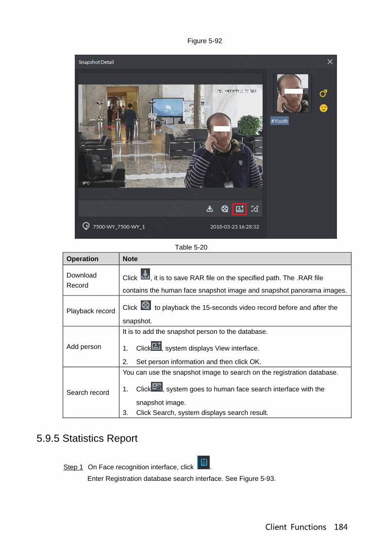
Client Functions 184
Figure 5-92
Table 5-20
Operation Note
Download
Record Click , it is to save RAR file on the specified path. The .RAR file
contains the human face snapshot image and snapshot panorama images.
Playback record Click to playback the 15-seconds video record before and after the
snapshot.
Add person
It is to add the snapshot person to the database.
1. Click , system displays View interface.
2. Set person information and then click OK.
Search record
You can use the snapshot image to search on the registration database.
1. Click , system goes to human face search interface with the
snapshot image.
3. Click Search, system displays search result.
5.9.5 Statistics Report
On Face recognition interface, click . Step 1
Enter Registration database search interface. See Figure 5-93.

Client Functions 185
Figure 5-93
Set search criteria. Step 2
Set video channel, report type and time.
Click Search. Step 3
The statistics search result is displayed. See Figure 5-94.
Figure 5-94
System displays results by line chart.
Click to display by pie chart.
Click to display by list.
Click Export, it is to export statistics result to .pdf file.

Client Functions 186
5.10 Road Monitoring Applications
The platform integrates vehicle module. It can search passed vehicles and search violation
records and alarm.
5.10.1 Preparations
Refer to chapter 4.6 Adding device to add ANR device on the platform manager.
Refer to chapter 4.13 Adding vehicle blacklist to add vehicle blacklist on the platform
manager.
Refer to Figure 5-95 for road monitor flows.
Figure 5-95
5.10.2 Road Monitor
Click ,on the New tab interface select ANPR. Step 1
Click ,system displays road monitor interface. Step 2
System displays emap in 1-window by default. You can manually switch window
amount. See Figure 5-96.

Client Functions 187
Figure 5-96
Click to select the ANPR channel. See Figure 5-97. Step 3
Figure 5-97
Select ANPR device and then click OK. Step 4
System displays the selected channel amount and the latest passing vehicle image on
the rolling pane. See Figure 5-98.

Client Functions 188
Figure 5-98
Double click the image to view image details. It includes plate number, snapshot time, Step 5
ANPR channel name, vehicle logo, vehicle color.
5.10.3 Searching Passed Vehicle
It is to search passing vehicle.
Click . Step 1
Enter Passed vehicle interface. See Figure 5-99.
Figure 5-99
Select video channel and search criteria. It includes time, plate number, plate color, Step 2
plate type, vehicle logo, vehicle body color and lane.
Click Search. Step 3
System displays search result. See Figure 5-100.

Client Functions 189
Figure 5-100
For the passed vehicle, you can view its detailed information, record and running track.
Refer to the operations listed below.
Click View mode ( ) or list mode ( ), it is to select different display mode.
Select a snapshot image and then click or double click the image,
system displays detailed information. See Figure 5-101. Move the cursor to the
middle to select the specified zone, you can zoom in it. See Figure 5-102.

Client Functions 190
Figure 5-101
Figure 5-102
Click to playback the 15-second video before and after the vehicle passed
time. See Figure 5-103. The video file is total 30 seconds. It is to display the
15-second video before and after the vehicle passed.
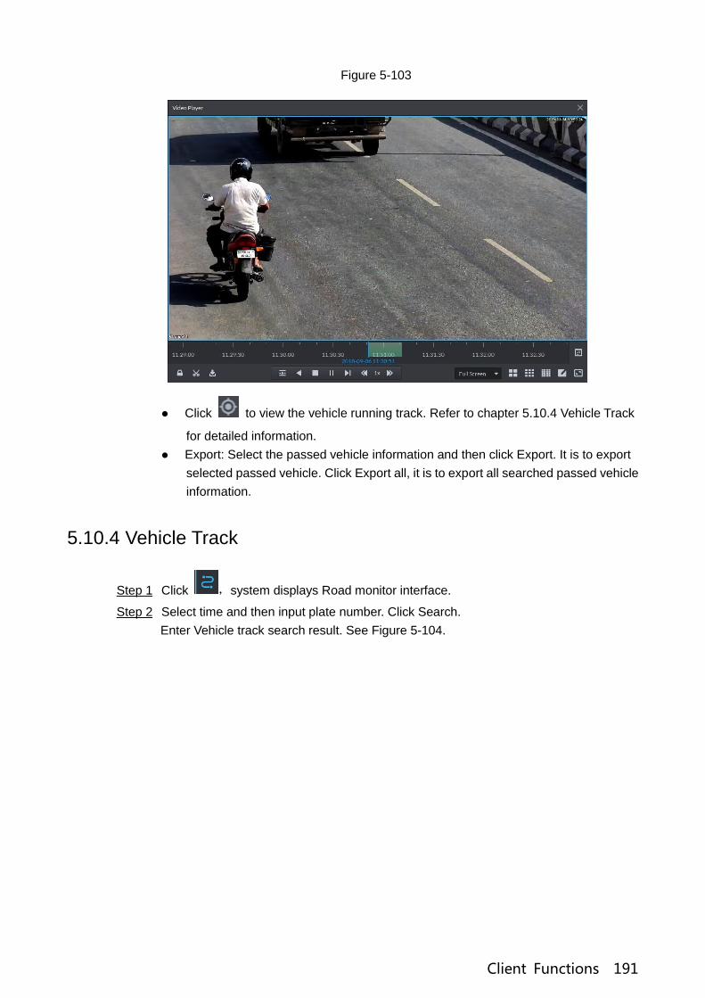
Client Functions 191
Figure 5-103
Click to view the vehicle running track. Refer to chapter 5.10.4 Vehicle Track
for detailed information.
Export: Select the passed vehicle information and then click Export. It is to export
selected passed vehicle. Click Export all, it is to export all searched passed vehicle
information.
5.10.4 Vehicle Track
Click ,system displays Road monitor interface. Step 1
Select time and then input plate number. Click Search. Step 2
Enter Vehicle track search result. See Figure 5-104.

Client Functions 192
Figure 5-104
Refer to the operations listed below.
Select the snapshot image and then click or double click the image,
you can view snapshot vehicle detailed information. See Figure 5-105. Move the
cursor to the middle to select the specified zone, you can zoom in it. See Figure
5-106.

Client Functions 193
Figure 5-105
Figure 5-106
Click Edit, it is to edit vehicle basic information.
Click Previous or Next to view the previous or the next search item.
Click the timeline that has the records, you can view the vehicle information of the
specified time. See Figure 5-107.

Client Functions 194
Figure 5-107
Select the snapshot image and then click the Generation path (track), you can view
the vehicle track on the map. See Figure 5-108.
Figure 5-108
5.10.5 Monitor Place
It is to view and confirm the alarm information.
Click 。 Step 1
Enter Monitor place interface. See Figure 5-109.

Client Functions 195
Figure 5-109
Select device channel, and then set time, plate number, speed. Click Search. Step 2
System displays search result. See Figure 5-110.
Figure 5-110
For the monitor record, you can view vehicle detailed information, corresponding video,
edit vehicle information. Refer to the operations listed below.
Click View mode( )or List mode( ),it is to select different display mode.
Select the snapshot image and then click or double click the image,
you can view snapshot vehicle detailed information. See Figure 5-111. Move the
cursor to the middle to select the specified zone, you can zoom in it. See Figure
5-106.

Client Functions 196
Figure 5-111
Figure 5-112
Click to playback the 15-second video before and after the vehicle passed
time. See Figure 5-113. The video file is total 30 seconds. It is to display the
15-second video before and after the vehicle passed.

Client Functions 197
Figure 5-113
Click to view the vehicle running track. Refer to chapter 5.10.4 Vehicle Track
for detailed information.
Export: Select the passed vehicle information and then click Export. It is to export
selected monitor position information. Click Export all, it is to export all monitor
position information.
5.11 Traffic
It is to search the vehicle traffic violation information from the ANPR device and vehicle flow
statistics. You can search speed measurement result from the specified range.
5.11.1 Preparations
Refer to chapter 4.6 Adding device to add ANPR device on the platform manager.
Refer to chapter 4.9 Configuring speed measurement on the range to set speed
measurement positions and its distance.
Refer to Figure 5-114 for flows information.

Client Functions 198
Figure 5-114
5.11.2 Searching Violation Information
It is to search vehicle violation information. The violation information is from the ANPR camera.
Click ,on the New tab interface select Traffic. Step 1
Enter Traffic interface.
Click 。 Step 2
Enter Violation management interface. See Figure 5-115.

Client Functions 199
Figure 5-115
Set search criteria. It includes time, plate number, and violation type. Step 3
Click Search. Step 4
System displays search result. See Figure 5-116.
Figure 5-116
For a violation item, you can view vehicle detailed information and violation record
video. Refer to the operations listed below.
Click View mode( )or List mode( ),it is to select different display mode.

Client Functions 200
Double click a violation item, you can view detailed vehicle information. See Figure
5-117.
Figure 5-117
Select a violation item and then click Export. It is to export selected violation
information. Click Export all, it is to export all searched violation results.
5.11.3 Search Vehicle Flows
It is to search the vehicle flow of one lane of one channel. The violation information is from the
ANPR camera. The default upload interval is 1 time/ minute (device supports 1~250
minute(s)/time). The vehicle flows include vehicle total flow, average speed, lane occupation
rate, flows of different vehicle types. The vehicle type includes small vehicle, passage vehicle,
small van and heavy-duty vehicle. The vehicle flow data can be saved for at least 2 years.
Click 。 Step 1
Enter Flow Searching interface. See Figure 5-118.

Client Functions 201
Figure 5-118
Select device channel, plate number, report type, interval, and then click Search. Step 2
System displays search result. See Figure 5-119.
Figure 5-119
For a flow record, you can view vehicle detailed information and corresponding record
file. Refer to the operations listed below.
Click Line chart mode( )or List mode( ),it is to select different display
mode.
Click Export all, it is to export all searched flow results.

Client Functions 202
5.11.4 Searching Speed during a Specified Range
It is to search the speed between the specified range.
Click 。 Step 1
Enter range speed interface. See Figure 5-120.
Figure 5-120
Select search range, time, lane number, plate color, average speed, type, and then Step 2
click Search.
System displays search result. See Figure 5-121.
NOTE
On thumbnail mode, system displays the earliest image of the current range as the
master image by default.

Client Functions 203
Figure 5-121
Refer to the operations listed below.
Click View mode( )or List mode( ),it is to select different display mode.
Double click the range speed measurement, you can view vehicle detailed
information. See Figure 5-122. Move the cursor to the middle to select the
specified zone, you can zoom in it. See Figure 5-123.

Client Functions 204
Figure 5-122
Figure 5-123
Select a range speed measurement search results, click Export to export selected
passed vehicle information. Click Export all, it is to export all searched passed
vehicle information.
5.12 Business Intelligence
NOTE
Refer to the general operations in current function module:

Client Functions 205
Click to display the value from the statistics report.
Click to zoom in the statistics of current zone. Click to zoom out the statistics.
5.12.1 Preparations
Refer to chapter 4.6 Adding device to register the smart network camera that supports
people counting function. Refer to the smart network camera user‟s manual to set camera
intelligent rule.
Refer to chapter 4.6 Adding device to add POS device and bind the video channel.
Refer to chapter 4.14 Adding store to add store information on the manager.
Refer to Figure 5-124 for business intelligence flows.
Figure 5-124
5.12.2 Business Report
Click , on the New tab interface select Business intelligence. Step 1
Enter Business intelligence interface.
Click . Step 2
Enter Operation report interface. See Figure 5-125.

Client Functions 206
Figure 5-125
Select a store from the organization tree and then set search date. Step 3
You can search by year, month, and date.
Click Search. Step 4
System displays search result. See Figure 5-126.
Figure 5-126
The report displays the selected store business running status.
Overview: It includes the store order amount of current period, sales amount and entry/exit
people amount.
Per customer transaction=Sales amount/order amount.
KPI=Purchased amount/total people amount.

Client Functions 207
Sales and orders:It is to display order amount and sales amount of current period and
previous period. For example, right now it is to searching the general status of the August
2018, it displays the order amount and sales amount of August 2018 and July 2018.
Store entering rate=Entering store amount/Passing store amount.
Store map: It is to display the corresponding map information of the added store. Refer to
chapter 4.14 Adding store.
5.12.3 People Flows Analysis
Click 。 Step 1
Enter people flow analysis interface. See Figure 5-127.
Figure 5-127
Select a store from the organization tree and then set selection date. Step 2
System supports search by date/month/year.
Click Search, system displays analysis result. Step 3
System displays Entrance analysis interface by default. See Figure 5-128.
System analyzes by enter/exit/stay/entering store rate.

Client Functions 208
Figure 5-128
Click Customer statistics tab. The interface is shown as in Figure 5-129.
System analyzes flows by age, gender and weather.
Figure 5-129
Click Indoor analysis tab, the interface is shown as below. See Figure 5-130.

Client Functions 209
Figure 5-130
Click Panoramic heatmap tab, the interface is shown as below. See Figure 5-131.
Figure 5-131
5.12.4 POS Data
Click . Step 1
Enter POS data interface. See Figure 5-132.

Client Functions 210
Figure 5-132
Select a store from the organization tree and then set selection date. Step 2
System supports search by date/month/year.
Click Search, system displays search results. Step 3
System displays Commodity analysis interface by default. See Figure 5-133.
Figure 5-133
Click Sales analysis tab, the interface is shown as below. See Figure 5-134.

Client Functions 211
Figure 5-134
Click Order analysis tab, the interface is shown as below. See Figure 5-135.
Figure 5-135
5.12.5 Structured Data
Click . Step 1
Enter structured data interface. See Figure 5-136.

Client Functions 212
Figure 5-136
Select a store from the organization tree and then set selection date. Step 2
System supports search by date/month/year.
Click Search, system displays search results. Step 3
System displays POS statistics interface by default. See Figure 5-137.
Figure 5-137
Click People count tab, the interface is shown as below. See Figure 5-138.

Client Functions 213
Figure 5-138
Click Export, it is to export search results.
Click Statistics, it is to view search results amount.
5.13 Time Synchronization
5.13.1 Device Time Synchronization
Device time synchronization is to synchronize front-end device time with platform server. The
platform server time is the basic time. DSS platform supports devices of Dahua, and ONVIF
protocol to synchronize time. It supports auto time synchronization function and manual time
synchronization function. The auto time synchronization refer to synchronize time with the
server at the specified interval and time. Manual time synchronization is to start time
synchronization manually, system responds immediately and then execute time
synchronization.
5.13.1.1 Auto Sync Time
Click and then on the New tab interface select System settings. Step 1
Click Time Sync and then check the box to enable the function. Set time Step 2
synchronization parameters. See Figure 5-139.

Client Functions 214
Figure 5-139
Click Save to save configuration information. Step 3
5.13.1.2 Manual Sync Time
Click and then on the New tab interface select System settings. Step 1
Click Immediately box. See Figure 5-140. Step 2
Figure 5-140
5.13.2 Time Synchronization on the Client
Time synchronization on the client is to synchronize client installed PC‟s time with platform
server. The platform server time is the basic time. It supports auto time synchronization function
and manual time synchronization function. The auto time synchronization refers to server starts
time synchronization at the specified interval and time. Manual time synchronization is to start
time synchronization manually, system responds immediately and then execute time
synchronization.
5.13.2.1 Auto Sync Time
Login DSS client. Step 1
Click at the top right corner. Enter Local config interface. Step 2
Click General tab and then enable client time sync function. Click Save. See Figure Step 3
5-141.
NOTE
After you enabled time sync function on the General interface, client begins the request
to the server immediately. It is to complete the time synchronization.

Client Functions 215
Figure 5-141
Click Save. Step 4
Login DSS manager, and then on the New tab interface select System settings. Step 5
Click Time sync and then check the box to enable the function. See time sync Step 6
parameters. See Figure 5-142.
Figure 5-142
Click Save to save configuration information. Step 7
5.13.2.2 Manual Time Sync
Login DSS client. Step 1
Click at the top right corner. Enter Local config interface. Step 2
Click General tab and then enable client time sync function. Click Save. See Figure Step 3
5-143.
NOTE
After you enabled time sync function on the General interface, client begins the request
to the server immediately. It is to complete the time synchronization.

Client Functions 216
Figure 5-143
Click Save. Step 4
Login DSS manager, and then on the New tab interface select System settings. Step 5
Click Immediately box. See Figure 5-144. Step 6
Figure 5-144

Client Functions 217
Service Module Introduction Appendix 1
Service Name Service Name Function Description Port Protocol
Type
Center Management
Service
DSS_WEB
Center management service is
to manage each service and
provide accessing port.
HTTPS:
443 TCP
Message Queue
Service
DSS_MQ
Message queue service is to
transfer messages between the
platforms.
61616 TCP
DMS
(Device
Management
Service)
DSS_DMS
Device management service is
to register front-end encoder,
receive alarm, transfer alarm
and send out sync time
command.
9200 TCP
MTS
(Media
Transmission
Service )
DSS_MTS
Media transmission service is to
get the audio/video bit stream
from the front-end device and
then transfer these data to the
SS, client and decoder.
9100 TCP
SS
(Storage Service)
DSS_SS
Storage service is to
storage/search/playback
record.
9320 TCP
VMS
(Video Matrix
Service)
DSS_VMS
Video matrix service is to login
the the decoder and send out
task to the decoder to output to
the TV wall.
Not fixed,
do not
need to
be
mapped
to the
outside.
TCP
MGW
(Media Gateway
Service)
DSS_MGW
Media gateway service is to
send out MTS service to the
decoder.
9090 TCP
ARS
(Auto Register
Service)
DSS_ARS
Auto register service is to listen,
login, or get bit streams to send
to MTS.
9500 TCP
PCPS
(ProxyList control
Proxy Service)
DSS_PCPS
ProxyList control Proxy Service
is to login Hikvision device,
Onvif device, and then get the
stream and transfer the data to
MTS.
5060
14509
UDP
TCP

Client Functions 218
ADS
(Alarm Dispatch
Service)
DSS_ADS
Alarm dispatch service is to
send out alarm information to
different objects according to
the plans.
9600 TCP
Related Documents