Ferdinand Schad KG Steigstraße 25-27 D-78600 Kolbingen Telephone +49 (0) 74 63 - 980 - 0 Fax +49 (0) 74 63 - 980 - 200 [email protected] www.schako.de Nozzle jet diffuser DSA

Welcome message from author
This document is posted to help you gain knowledge. Please leave a comment to let me know what you think about it! Share it to your friends and learn new things together.
Transcript
Ferdinand Schad KGSteigstraße 25-27
D-78600 KolbingenTelephone +49 (0) 74 63 - 980 - 0
Fax +49 (0) 74 63 - 980 - [email protected]
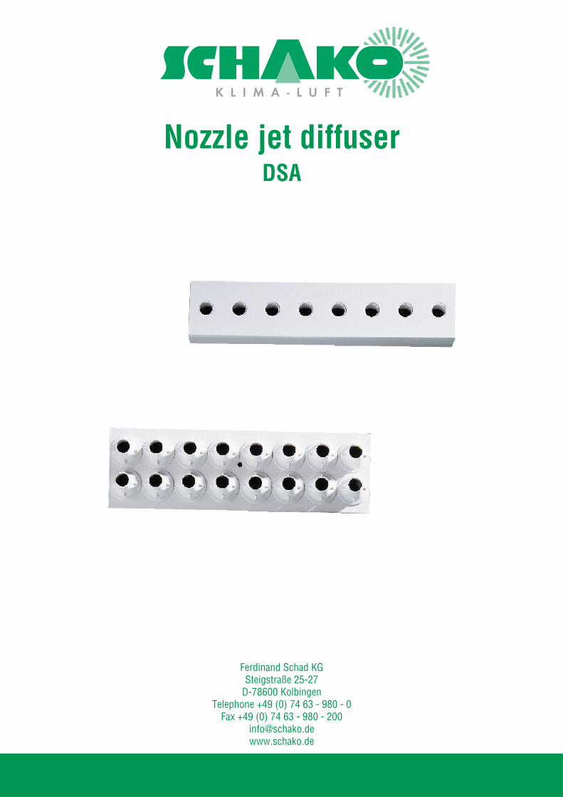
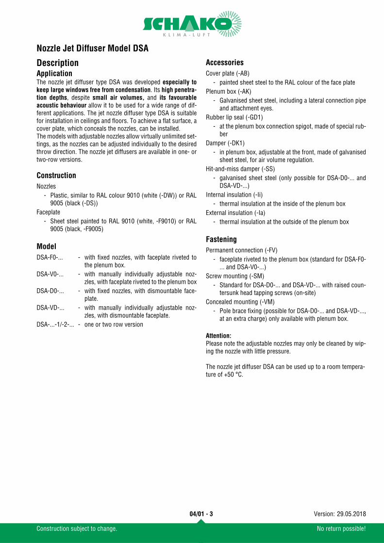
Nozzle jet diffuserDSA

Contents
Construction subject to change. No return possible!
Nozzle Jet Diffuser Model DSA
04/01 - 2 29.05.2018Version:
Description ........................................................................................................................................3Application ................................................................................................................................................................................. 3Construction .............................................................................................................................................................................. 3Model ......................................................................................................................................................................................... 3Accessories ................................................................................................................................................................................ 3Fastening ................................................................................................................................................................................... 3
Models and dimensions .........................................................................................................................4Dimensions ................................................................................................................................................................................ 4Band design ............................................................................................................................................................................... 6Dimensions of accessories ........................................................................................................................................................ 7Fastening methods ..................................................................................................................................................................... 8
Technical data ....................................................................................................................................8Pressure loss and noise level ..................................................................................................................................................... 8Maximum end velocity of jet ...................................................................................................................................................... 9Maximum penetration .............................................................................................................................................................. 10Temperature and induction ratios ............................................................................................................................................ 11
Legend ........................................................................................................................................... 12Order details DSA .............................................................................................................................. 13Order details AK DSA .......................................................................................................................... 14Specification texts .............................................................................................................................. 15
Nozzle Jet Diffuser Model DSA
04/01 - 3
Construction subject to change. No return possible!
29.05.2018Version:
DescriptionApplicationThe nozzle jet diffuser type DSA was developed especially tokeep large windows free from condensation. Its high penetra-tion depths, despite small air volumes, and its favourableacoustic behaviour allow it to be used for a wide range of dif-ferent applications. The jet nozzle diffuser type DSA is suitablefor installation in ceilings and floors. To achieve a flat surface, acover plate, which conceals the nozzles, can be installed.The models with adjustable nozzles allow virtually unlimited set-tings, as the nozzles can be adjusted individually to the desiredthrow direction. The nozzle jet diffusers are available in one- ortwo-row versions.
Construction
Model
Accessories
Fastening
Attention:Please note the adjustable nozzles may only be cleaned by wip-ing the nozzle with little pressure.
The nozzle jet diffuser DSA can be used up to a room tempera-ture of +50 °C.
Nozzles- Plastic, similar to RAL colour 9010 (white (-DW)) or RAL
9005 (black (-DS))Faceplate
- Sheet steel painted to RAL 9010 (white, -F9010) or RAL9005 (black, -F9005)
DSA-F0-... - with fixed nozzles, with faceplate riveted tothe plenum box.
DSA-V0-... - with manually individually adjustable noz-zles, with faceplate riveted to the plenum box
DSA-D0-... - with fixed nozzles, with dismountable face-plate.
DSA-VD-... - with manually individually adjustable noz-zles, with dismountable faceplate.
DSA-...-1/-2-... - one or two row version
Cover plate (-AB)- painted sheet steel to the RAL colour of the face plate
Plenum box (-AK)- Galvanised sheet steel, including a lateral connection pipe
and attachment eyes.Rubber lip seal (-GD1)
- at the plenum box connection spigot, made of special rub-ber
Damper (-DK1)- in plenum box, adjustable at the front, made of galvanised
sheet steel, for air volume regulation.Hit-and-miss damper (-SS)
- galvanised sheet steel (only possible for DSA-D0-... andDSA-VD-...)
Internal insulation (-Ii)- thermal insulation at the inside of the plenum box
External insulation (-Ia)- thermal insulation at the outside of the plenum box
Permanent connection (-FV)- faceplate riveted to the plenum box (standard for DSA-F0-
... and DSA-V0-...)Screw mounting (-SM)
- Standard for DSA-D0-... and DSA-VD-... with raised coun-tersunk head tapping screws (on-site)
Concealed mounting (-VM)- Pole brace fixing (possible for DSA-D0-... and DSA-VD-...,
at an extra charge) only available with plenum box.
Nozzle Jet Diffuser Model DSA
04/01 - 4
Construction subject to change. No return possible!
29.05.2018Version:
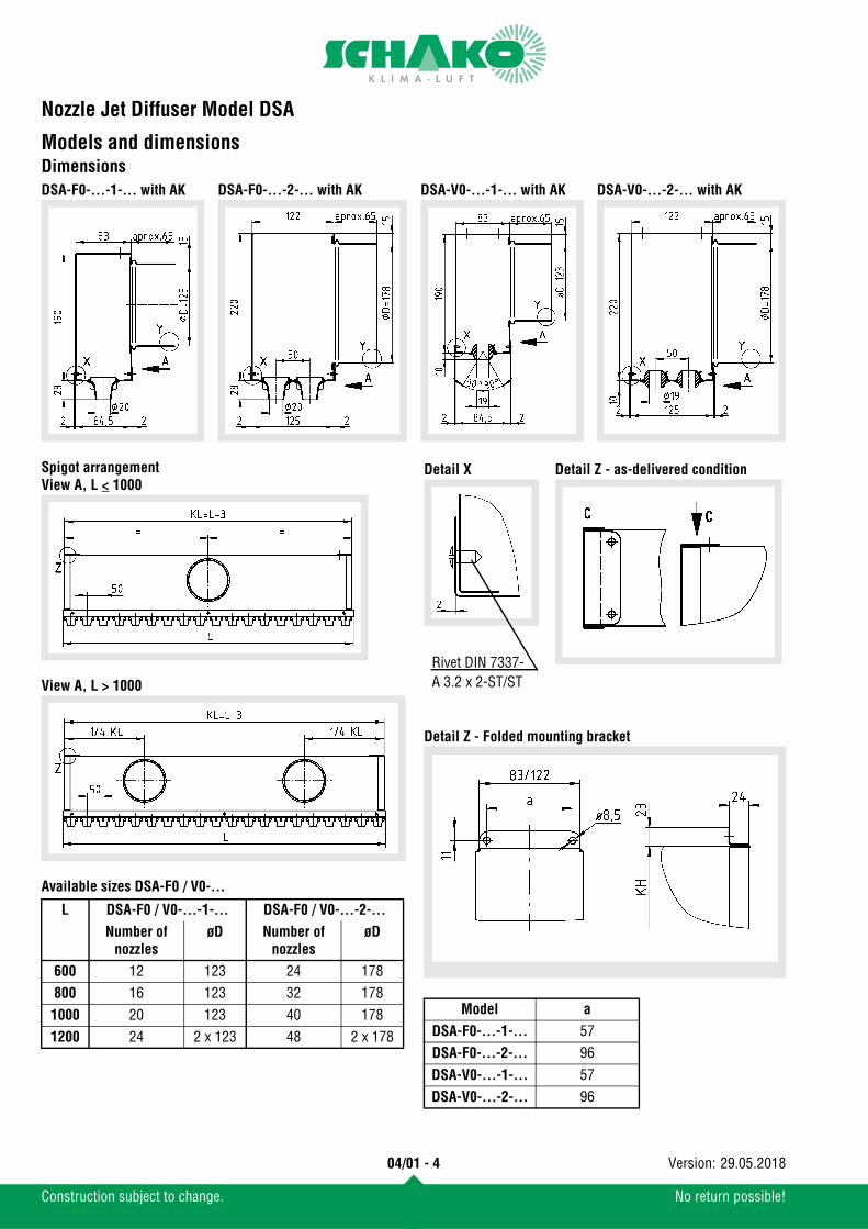
Models and dimensionsDimensions
Spigot arrangementView A, L < 1000
View A, L > 1000
Available sizes DSA-F0 / V0-...
Detail Z - Folded mounting bracket
DSA-F0-...-1-... with AK DSA-F0-...-2-... with AK DSA-V0-...-2-... with AKDSA-V0-...-1-... with AK
L DSA-F0 / V0-...-1-... DSA-F0 / V0-...-2-...
Number of nozzles
øD Number of nozzles
øD
600 12 123 24 178800 16 123 32 1781000 20 123 40 1781200 24 2 x 123 48 2 x 178
Model a
DSA-F0-...-1-... 57DSA-F0-...-2-... 96DSA-V0-...-1-... 57DSA-V0-...-2-... 96
Detail X Detail Z - as-delivered condition
Rivet DIN 7337-A 3.2 x 2-ST/ST

Nozzle Jet Diffuser Model DSA
04/01 - 5
Construction subject to change. No return possible!
29.05.2018Version:
Spigot arrangementView B, L < 1000
View B, L > 1000
Available sizes DSA-D0 / VD-...
Detail Z - Folded mounting bracket
DSA-D0-...-1-... with ASK DSA-D0-...-2-... with ASK DSA-VD-...-1-... with ASK DSA-VD-...-2-... with ASK
L L1 DSA-D0-...-1-... / DSA-VD-...-1-...
DSA-D0-...-2-... / DSA-VD-...-2-...
Number of nozzles
øD Number of nozzles
øD
625 650 12 123 24 178825 850 16 123 32 1781025 1050 20 123 40 1781225 1250 24 2 x 123 48 2 x 178
Model a
DSA-D0-...-1-... 42DSA-D0-...-2-... 92DSA-VD-...-1-... 42DSA-VD-...-2-... 92
Detail Z - as-delivered condition Detail W
Nozzle Jet Diffuser Model DSA
04/01 - 6
Construction subject to change. No return possible!
29.05.2018Version:
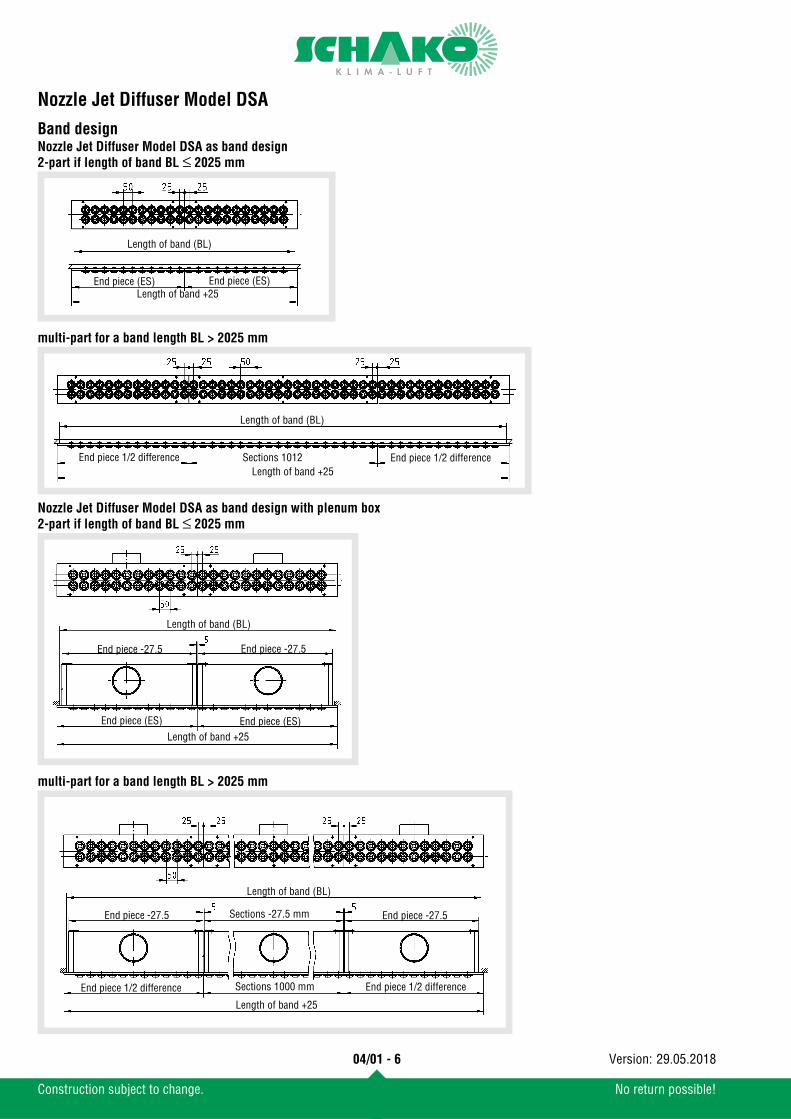
Band designNozzle Jet Diffuser Model DSA as band design2-part if length of band BL ≤ 2025 mm
multi-part for a band length BL > 2025 mm
Nozzle Jet Diffuser Model DSA as band design with plenum box2-part if length of band BL ≤ 2025 mm
multi-part for a band length BL > 2025 mm
Length of band (BL)
End piece (ES) End piece (ES)Length of band +25
End piece 1/2 difference Sections 1012 End piece 1/2 differenceLength of band +25
Length of band (BL)
Length of band (BL)
End piece -27.5 End piece -27.5
Length of band +25End piece (ES)End piece (ES)
End piece 1/2 difference End piece 1/2 differenceSections 1000 mm
Length of band +25
Sections -27.5 mmEnd piece -27.5
Length of band (BL)
End piece -27.5
Nozzle Jet Diffuser Model DSA
04/01 - 7
Construction subject to change. No return possible!
29.05.2018Version:
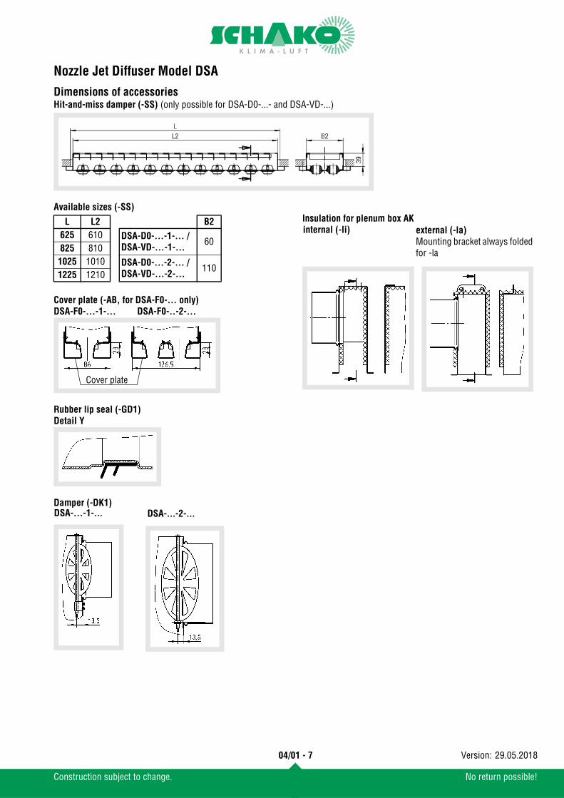
Dimensions of accessoriesHit-and-miss damper (-SS) (only possible for DSA-D0-...- and DSA-VD-...)
Available sizes (-SS)
Cover plate (-AB, for DSA-F0-... only)DSA-F0-...-1-... DSA-F0-..-2-...
Rubber lip seal (-GD1)Detail Y
Damper (-DK1)
Insulation for plenum box AKL L2 B2625 610 DSA-D0-...-1-... /
DSA-VD-...-1-...60
825 8101025 1010 DSA-D0-...-2-... /
DSA-VD-...-2-...110
1225 1210
Cover plate
DSA-...-1-... DSA-...-2-...
external (-la)Mounting bracket always folded for -la
internal (-li)
Nozzle Jet Diffuser Model DSA
04/01 - 8
Construction subject to change. No return possible!
29.05.2018Version:
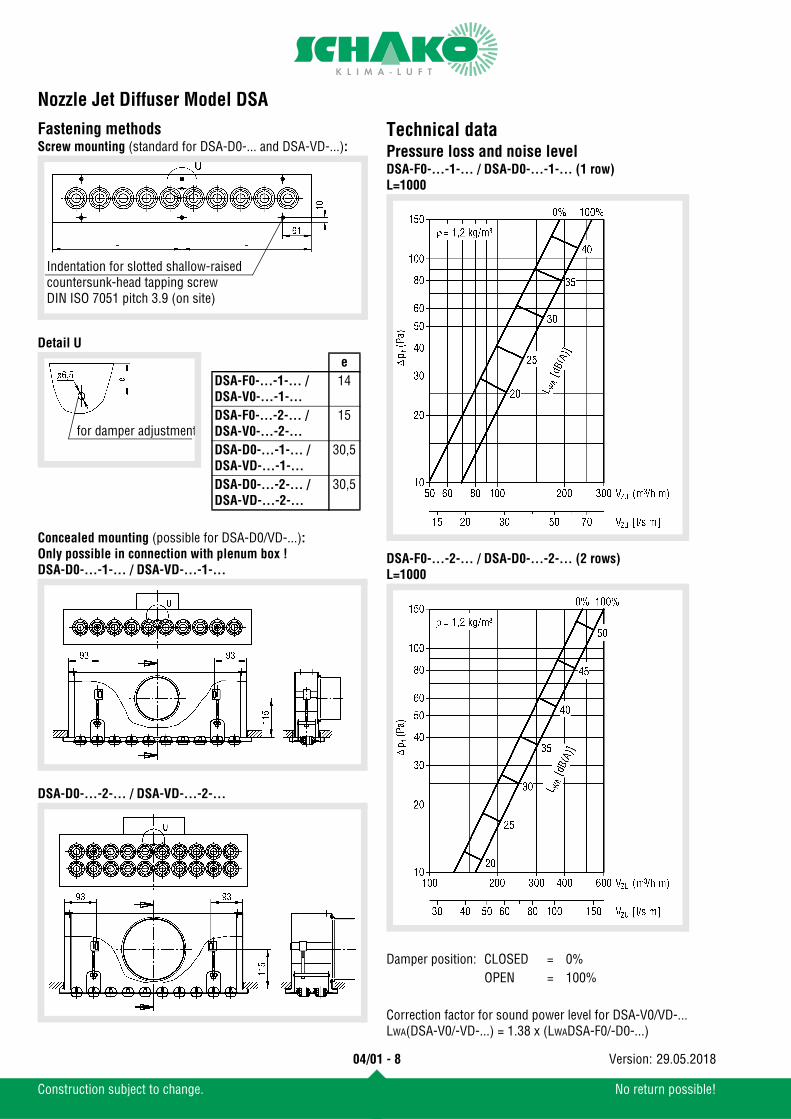
Fastening methodsScrew mounting (standard for DSA-D0-... and DSA-VD-...):
Detail U
Concealed mounting (possible for DSA-D0/VD-...):Only possible in connection with plenum box !DSA-D0-...-1-... / DSA-VD-...-1-...
DSA-D0-...-2-... / DSA-VD-...-2-...
Technical dataPressure loss and noise levelDSA-F0-...-1-... / DSA-D0-...-1-... (1 row)L=1000
DSA-F0-...-2-... / DSA-D0-...-2-... (2 rows)L=1000
Indentation for slotted shallow-raised countersunk-head tapping screwDIN ISO 7051 pitch 3.9 (on site)
for damper adjustment
eDSA-F0-...-1-... / DSA-V0-...-1-...
14
DSA-F0-...-2-... / DSA-V0-...-2-...
15
DSA-D0-...-1-... / DSA-VD-...-1-...
30,5
DSA-D0-...-2-... / DSA-VD-...-2-...
30,5
Damper position: CLOSED = 0%OPEN = 100%
Correction factor for sound power level for DSA-V0/VD-... LWA(DSA-V0/-VD-...) = 1.38 x (LWADSA-F0/-D0-...)
Nozzle Jet Diffuser Model DSA
04/01 - 9
Construction subject to change. No return possible!
29.05.2018Version:
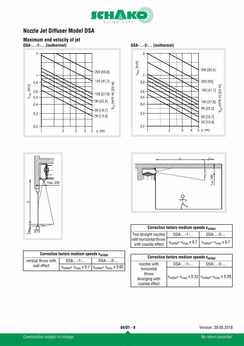
Maximum end velocity of jetDSA-...-1-... (isothermal) DSA-...-2-... (isothermal)
Correction factors medium speeds vmittel
vertical throw with wall effect
DSA-...-1-... DSA-...-2-...vmittel= vmax x 0.7 vmittel= vmax x 0.65
Correction factors medium speeds vmittel
Two straight nozzles with horizontal throw
with coanda effect
DSA-...-1-... DSA-...-2-...
vmittel= vmax x 0.7 vmittel= vmax x 0.7
Correction factors medium speeds vmittel
nozzles with horizontal
throwdiverging with coanda effect
DSA-...-1-... DSA-...-2-...
vmittel= vmax x 0.33 vmittel= vmax x 0.28

Nozzle Jet Diffuser Model DSA
04/01 - 10
Construction subject to change. No return possible!
29.05.2018Version:
Maximum penetrationIn heating modeDSA-...-1 DSA-...-2-...
DSA-...-1-... DSA-...-2-...

Nozzle Jet Diffuser Model DSA
04/01 - 11
Construction subject to change. No return possible!
29.05.2018Version:
Temperature and induction ratiosDSA-F0-...-1-... / DSA-D0-...-1-...
Correction factorfor DSA-F0-...-2-... / DSA-D0-...-2-...
DSA-V0-...-1-... / DSA-VD-...-1-...Correction factorfor DSA-V0-...-2-... / DSA-VD-...-2-...
i x 0.77TV x 1.41
i x 0.77TV x 1.41
Nozzle Jet Diffuser Model DSA
04/01 - 12
Construction subject to change. No return possible!
29.05.2018Version:
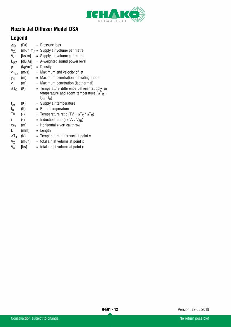
LegendΔpt (Pa) = Pressure lossVZU (m³/h m) = Supply air volume per metreVZU [l/s m] = Supply air volume per metreLWA [dB(A)] = A-weighted sound power levelρ (kg/m³) = Densityvmax (m/s) = Maximum end velocity of jetyH (m) = Maximum penetration in heating modeyi (m) = Maximum penetration (isothermal)ΔTO (K) = Temperature difference between supply air
temperature and room temperature (ΔTO =tZU - tR)
tzu (K) = Supply air temperaturetR (K) = Room temperatureTV (-) = Temperature ratio (TV = ΔTX / ΔTO)i (-) = Induction ratio (i = VX / VZU)x+y (m) = Horizontal + vertical throwL (mm) = LengthΔTX (K) = Temperature difference at point xVX (m³/h) = total air jet volume at point xVX [l/s] = total air jet volume at point x

Nozzle Jet Diffuser Model DSA
04/01 - 13
Construction subject to change. No return possible!
29.05.2018Version:
Order details DSA
SampleDSA-F0-00600-1-N-SB-9010-DW-FV-SN-A0
Nozzle jet diffuser type DSA I with fixed nozzles and faceplate riveted to the plenum box I length 600 mm I one row I single length I sheet steel I painted to RAL colour 9010 I white similar to RAL9010 I with fixed connection I without hit-and-miss damper I without cover plate
Order details
01 - Type
02 - Model
03 - Length
04 - Height
05 - Single / band design
06 - Material
07 - Paint
08 - Nozzle colour
09 - Fastening
10 - Hit-and-miss damper
11 - Cover plate
01 02 03 04 05Type Model Length Height Single / band designExampleDSA -F0 -00600 -1 -N
06 07 08 09 10 11Material Paint Nozzle colour Fastening Hit-and-miss damper Cover plate
-SB -9010 -DW -FV -SN -A0
DSA = Nozzle Jet Diffuser Model DSA
F0 = with fixed nozzles and faceplate riveted to the plenum box
V0 = with manually individually adjustable nozzles and face-plate riveted to the plenum box
D0 = with fixed nozzles and faceplate dismountableVD = with manually individually adjustable nozzles and face-
plate dismountable
00600 = Grille length 600 mm (DSA-F0-... / DSA-V0-...)00625 = Grille length 625 mm (DSA-D0-... / DSA-VD-...)00800 = Grille length 800 mm (DSA-F0-... / DSA-V0-...)00825 = Grille length 825 mm (DSA-D0-... / DSA-VD-...)01000 = Grille length 1000 mm (DSA-F0-... / DSA-V0-...)01025 = Grille length 1025 mm (DSA-D0-... / DSA-VD-...)01200 = Grille length 1200 mm (DSA-F0-... / DSA-V0-...)01225 = Grille length 1225 mm (DSA-D0-... / DSA-VD-...)xxxxx = Band design > 1200 mm (always with 5 digits)
1 = 1 row2 = 2 row
N = Single lengthB = Band design
SB = Sheet steel (standard)
9010 = RAL 9010 (white, standard)9005 = RAL9005 (black)xxxx = painted to RAL colour of your choice (always with 4
digits)
DS = black, similar to RAL 9005DA = white aluminium, similar to RAL9006DW = white, similar to RAL 9010 (standard)
FV = Permanent connection (standard for DSA-F0-... and DSA-V0-...)
SM = Screw mounting (standard for DSA-D0-... and DSA-VD-...)
VM = Concealed mounting (only possible for DSA-D0-... and DSA-VD-...)
SN = without hit-and-miss damperSS = with hit-and-miss damper (only possible for DSA-
DO-... and DSA-VD-...)
A0 = without cover plate (standard)Return air = with cover plate (only for DSA-F0, painted to
the RAL colour of the face plate)
Nozzle Jet Diffuser Model DSA
04/01 - 14
Construction subject to change. No return possible!
29.05.2018Version:
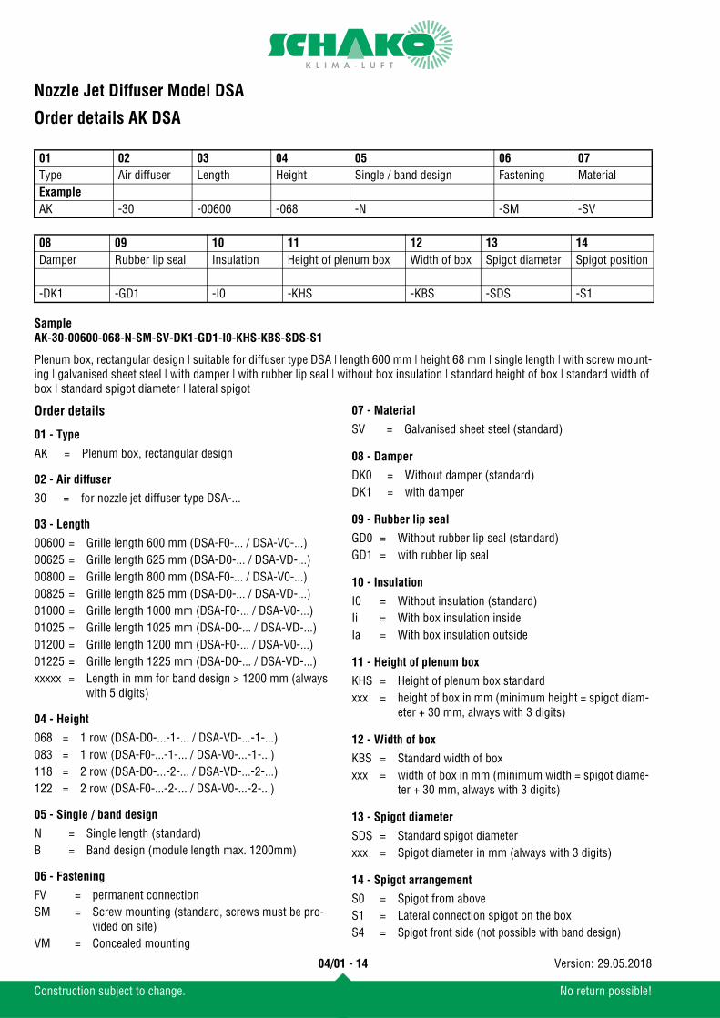
Order details AK DSA
SampleAK-30-00600-068-N-SM-SV-DK1-GD1-I0-KHS-KBS-SDS-S1
Plenum box, rectangular design | suitable for diffuser type DSA | length 600 mm | height 68 mm | single length | with screw mount-ing | galvanised sheet steel | with damper | with rubber lip seal | without box insulation | standard height of box | standard width of box | standard spigot diameter | lateral spigot
Order details
01 - Type
02 - Air diffuser
03 - Length
04 - Height
05 - Single / band design
06 - Fastening
07 - Material
08 - Damper
09 - Rubber lip seal
10 - Insulation
11 - Height of plenum box
12 - Width of box
13 - Spigot diameter
14 - Spigot arrangement
01 02 03 04 05 06 07Type Air diffuser Length Height Single / band design Fastening MaterialExampleAK -30 -00600 -068 -N -SM -SV
08 09 10 11 12 13 14Damper Rubber lip seal Insulation Height of plenum box Width of box Spigot diameter Spigot position
-DK1 -GD1 -I0 -KHS -KBS -SDS -S1
AK = Plenum box, rectangular design
30 = for nozzle jet diffuser type DSA-...
00600 = Grille length 600 mm (DSA-F0-... / DSA-V0-...)00625 = Grille length 625 mm (DSA-D0-... / DSA-VD-...)00800 = Grille length 800 mm (DSA-F0-... / DSA-V0-...)00825 = Grille length 825 mm (DSA-D0-... / DSA-VD-...)01000 = Grille length 1000 mm (DSA-F0-... / DSA-V0-...)01025 = Grille length 1025 mm (DSA-D0-... / DSA-VD-...)01200 = Grille length 1200 mm (DSA-F0-... / DSA-V0-...)01225 = Grille length 1225 mm (DSA-D0-... / DSA-VD-...)xxxxx = Length in mm for band design > 1200 mm (always
with 5 digits)
068 = 1 row (DSA-D0-...-1-... / DSA-VD-...-1-...)083 = 1 row (DSA-F0-...-1-... / DSA-V0-...-1-...)118 = 2 row (DSA-D0-...-2-... / DSA-VD-...-2-...)122 = 2 row (DSA-F0-...-2-... / DSA-V0-...-2-...)
N = Single length (standard)B = Band design (module length max. 1200mm)
FV = permanent connectionSM = Screw mounting (standard, screws must be pro-
vided on site)VM = Concealed mounting
SV = Galvanised sheet steel (standard)
DK0 = Without damper (standard)DK1 = with damper
GD0 = Without rubber lip seal (standard)GD1 = with rubber lip seal
I0 = Without insulation (standard)Ii = With box insulation insideIa = With box insulation outside
KHS = Height of plenum box standardxxx = height of box in mm (minimum height = spigot diam-
eter + 30 mm, always with 3 digits)
KBS = Standard width of boxxxx = width of box in mm (minimum width = spigot diame-
ter + 30 mm, always with 3 digits)
SDS = Standard spigot diameterxxx = Spigot diameter in mm (always with 3 digits)
S0 = Spigot from aboveS1 = Lateral connection spigot on the boxS4 = Spigot front side (not possible with band design)
Nozzle Jet Diffuser Model DSA
04/01 - 15
Construction subject to change. No return possible!
29.05.2018Version:
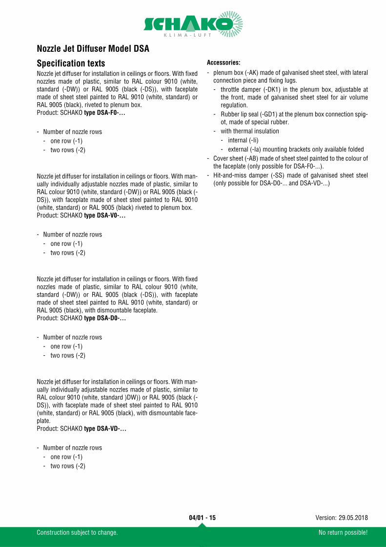
Specification textsNozzle jet diffuser for installation in ceilings or floors. With fixednozzles made of plastic, similar to RAL colour 9010 (white,standard (-DW)) or RAL 9005 (black (-DS)), with faceplatemade of sheet steel painted to RAL 9010 (white, standard) orRAL 9005 (black), riveted to plenum box.Product: SCHAKO type DSA-F0-...
Nozzle jet diffuser for installation in ceilings or floors. With man-ually individually adjustable nozzles made of plastic, similar toRAL colour 9010 (white, standard (-DW)) or RAL 9005 (black (-DS)), with faceplate made of sheet steel painted to RAL 9010(white, standard) or RAL 9005 (black) riveted to plenum box.Product: SCHAKO type DSA-V0-...
Nozzle jet diffuser for installation in ceilings or floors. With fixednozzles made of plastic, similar to RAL colour 9010 (white,standard (-DW)) or RAL 9005 (black (-DS)), with faceplatemade of sheet steel painted to RAL 9010 (white, standard) orRAL 9005 (black), with dismountable faceplate.Product: SCHAKO type DSA-D0-...
Nozzle jet diffuser for installation in ceilings or floors. With man-ually individually adjustable nozzles made of plastic, similar toRAL colour 9010 (white, standard )DW)) or RAL 9005 (black (-DS)), with faceplate made of sheet steel painted to RAL 9010(white, standard) or RAL 9005 (black), with dismountable face-plate.Product: SCHAKO type DSA-VD-...
Accessories:
- Number of nozzle rows- one row (-1)- two rows (-2)
- Number of nozzle rows- one row (-1)- two rows (-2)
- Number of nozzle rows- one row (-1)- two rows (-2)
- Number of nozzle rows- one row (-1)- two rows (-2)
- plenum box (-AK) made of galvanised sheet steel, with lateralconnection piece and fixing lugs.- throttle damper (-DK1) in the plenum box, adjustable at
the front, made of galvanised sheet steel for air volumeregulation.
- Rubber lip seal (-GD1) at the plenum box connection spig-ot, made of special rubber.
- with thermal insulation- internal (-Ii)- external (-Ia) mounting brackets only available folded
- Cover sheet (-AB) made of sheet steel painted to the colour ofthe faceplate (only possible for DSA-F0-...).
- Hit-and-miss damper (-SS) made of galvanised sheet steel(only possible for DSA-D0-... and DSA-VD-...)
Related Documents