Numerical analysis of spontaneously condensing phenomena in nozzle of steam-jet vacuum pump Xiao-Dong Wang a, * , Jing-Liang Dong a , Tian Wang b , Ji-Yuan Tu c a Vacuum and Fluid Research Centre, School of Mechanical Engineering & Automation, Northeastern University, Shenyang 110004, PR China b Shenyang Normal University, Shenyang 110034, PR China c School of Aerospace, Mechanical and Manufacturing Engineering, RMIT University, Victoria 3083, Australia article info Article history: Received 22 September 2010 Received in revised form 4 November 2010 Accepted 16 February 2011 Keywords: Steam-jet pump Flow in nozzle Spontaneous condensation CFD modelling CFD simulation abstract The primary fluid in a steam-jet vacuum pump is not assumed as a perfect gas as general research in the present study. A mathematic model based on the wet steam model for transonic flow is proposed to investigate the flow behaviours of primary fluid in the nozzle of a steam-jet vacuum pump. The simu- lation based on a wet steam model was carried out to predict the flow characteristics of primary fluid along the nozzle axis by a commercial computational fluid dynamics (CFD) code (FLUENT6.3). The simulation results showed that there was spontaneous condensation as the supersonic flow passing through the nozzle and the simulation results had a good agreement with the experimental data. It is found from the numerical simulation results that the steam flow characteristics in nozzle are quite different from a wet steam model and a perfect gas assumption: the outlet pressure of the nozzle pre- dicted in the present study is higher than that as the primary fluid assumed as perfect gas, the outlet velocity is about 10% lower than that as the primary fluid assumed as a perfect gas, and the temperature at the outlet of the nozzle is much higher than that as the primary fluid assumed as a perfect gas. The simulation results demonstrate that the thermo-positive process due to steam condensation would hinder the supersonic expanding flow process in nozzle and depress the efficiency of the nozzle which would affect the pumping performance of steam-jet pump. Ó 2011 Elsevier Ltd. All rights reserved. 1. Introduction The steam-jet vacuum pump is an important equipment widely used in chemistry, petroleum, metallurgy, refrigeration and food industry to obtain a vacuum environment for various special techniques. A steam-jet pump consists of a nozzle, a mixing chamber, throat and a diffuser as shown in Fig. 1 [1], and its pres- sure and velocity distributions along the pump axis are described in the same diagram. The primary fluid (steam) is accelerated with high pressure (0.3e1.6 MPa) through a nozzle and obtains super- sonic flow at the outlet of the nozzle resulting in a low pressure (vacuum). The supersonic primary steam entrains and draws the secondary fluid into the mixing chamber, where the secondary fluid is accelerated. The mixing process of energy and momentum exchange between primary and secondary flow happens through the mixing chamber. A normal shock wave is induced in the throat and the velocity of mixing fluid suddenly drops to subsonic value. Further compression is achieved when the mixed flow passes through the diffuser. The mixing flow structure is complicated in the pump due to the transonic flow and it is difficult to describe by traditional methods [2]. Computational fluid dynamics (CFD) is a good choice as a research tool to investigate and predict the complicated flow in a steam-jet pump [3e5]. The typical performance curve for special primary fluid pres- sure, temperature and secondary fluid pressure is shown in Fig. 2 [6]. There are three regions: critical mode (choked flow in the mixing chamber), subcritical mode (unchoked flow in the mixing chamber) and malfunction (reversed flow in the mixing chamber) depending on different back pressure (P B , outlet pressure of pump). As P B is below the critical value ðP * B Þ, the entrainment ratio (E m , the ratio of mass flow rate of secondary fluid to that of primary fluid) remains constant. When P B is increased higher than P * B , the E m begins to fall down rapidly. The nozzle in a steam-jet pump is the key part in which steam is accelerated from stagnation state to supersonic flow to obtain a vacuum at the nozzle outlet and the temperature of steam passing through a nozzle would be much lower than the stagnation temperature due to inner energy partly transformed into kinetic * Corresponding author. Tel.: þ86 24 8368 7618; fax: þ86 24 8368 0459. E-mail address: [email protected] (X.-D. Wang). Contents lists available at ScienceDirect Vacuum journal homepage: www.elsevier.com/locate/vacuum 0042-207X/$ e see front matter Ó 2011 Elsevier Ltd. All rights reserved. doi:10.1016/j.vacuum.2011.02.016 Vacuum 86 (2012) 861e866

Welcome message from author
This document is posted to help you gain knowledge. Please leave a comment to let me know what you think about it! Share it to your friends and learn new things together.
Transcript

lable at ScienceDirect
Vacuum 86 (2012) 861e866
Contents lists avai
Vacuum
journal homepage: www.elsevier .com/locate/vacuum
Numerical analysis of spontaneously condensing phenomena in nozzleof steam-jet vacuum pump
Xiao-Dong Wang a,*, Jing-Liang Dong a, Tian Wang b, Ji-Yuan Tu c
aVacuum and Fluid Research Centre, School of Mechanical Engineering & Automation, Northeastern University, Shenyang 110004, PR Chinab Shenyang Normal University, Shenyang 110034, PR Chinac School of Aerospace, Mechanical and Manufacturing Engineering, RMIT University, Victoria 3083, Australia
a r t i c l e i n f o
Article history:Received 22 September 2010Received in revised form4 November 2010Accepted 16 February 2011
Keywords:Steam-jet pumpFlow in nozzleSpontaneous condensationCFD modellingCFD simulation
* Corresponding author. Tel.: þ86 24 8368 7618; faE-mail address: [email protected] (X.-D. W
0042-207X/$ e see front matter � 2011 Elsevier Ltd.doi:10.1016/j.vacuum.2011.02.016
a b s t r a c t
The primary fluid in a steam-jet vacuum pump is not assumed as a perfect gas as general research in thepresent study. A mathematic model based on the wet steam model for transonic flow is proposed toinvestigate the flow behaviours of primary fluid in the nozzle of a steam-jet vacuum pump. The simu-lation based on a wet steam model was carried out to predict the flow characteristics of primary fluidalong the nozzle axis by a commercial computational fluid dynamics (CFD) code (FLUENT6.3). Thesimulation results showed that there was spontaneous condensation as the supersonic flow passingthrough the nozzle and the simulation results had a good agreement with the experimental data. It isfound from the numerical simulation results that the steam flow characteristics in nozzle are quitedifferent from a wet steam model and a perfect gas assumption: the outlet pressure of the nozzle pre-dicted in the present study is higher than that as the primary fluid assumed as perfect gas, the outletvelocity is about 10% lower than that as the primary fluid assumed as a perfect gas, and the temperatureat the outlet of the nozzle is much higher than that as the primary fluid assumed as a perfect gas. Thesimulation results demonstrate that the thermo-positive process due to steam condensation wouldhinder the supersonic expanding flow process in nozzle and depress the efficiency of the nozzle whichwould affect the pumping performance of steam-jet pump.
� 2011 Elsevier Ltd. All rights reserved.
1. Introduction
The steam-jet vacuum pump is an important equipment widelyused in chemistry, petroleum, metallurgy, refrigeration and foodindustry to obtain a vacuum environment for various specialtechniques. A steam-jet pump consists of a nozzle, a mixingchamber, throat and a diffuser as shown in Fig. 1 [1], and its pres-sure and velocity distributions along the pump axis are described inthe same diagram. The primary fluid (steam) is accelerated withhigh pressure (0.3e1.6 MPa) through a nozzle and obtains super-sonic flow at the outlet of the nozzle resulting in a low pressure(vacuum). The supersonic primary steam entrains and draws thesecondary fluid into the mixing chamber, where the secondaryfluid is accelerated. The mixing process of energy and momentumexchange between primary and secondary flow happens throughthe mixing chamber. A normal shock wave is induced in the throatand the velocity of mixing fluid suddenly drops to subsonic value.
x: þ86 24 8368 0459.ang).
All rights reserved.
Further compression is achieved when the mixed flow passesthrough the diffuser.
Themixing flow structure is complicated in the pump due to thetransonic flow and it is difficult to describe by traditional methods[2]. Computational fluid dynamics (CFD) is a good choice asa research tool to investigate and predict the complicated flow ina steam-jet pump [3e5].
The typical performance curve for special primary fluid pres-sure, temperature and secondary fluid pressure is shown in Fig. 2[6]. There are three regions: critical mode (choked flow in themixing chamber), subcritical mode (unchoked flow in the mixingchamber) and malfunction (reversed flow in the mixing chamber)depending on different back pressure (PB, outlet pressure of pump).As PB is below the critical value ðP*BÞ, the entrainment ratio (Em, theratio of mass flow rate of secondary fluid to that of primary fluid)remains constant. When PB is increased higher than P*B, the Embegins to fall down rapidly.
The nozzle in a steam-jet pump is the key part inwhich steam isaccelerated from stagnation state to supersonic flow to obtaina vacuum at the nozzle outlet and the temperature of steam passingthrough a nozzle would be much lower than the stagnationtemperature due to inner energy partly transformed into kinetic

Nomenclature
b mass fractionr, rl, rv mixture density, liquid density, vapour densityu velocityG mass generation rater droplet average radiusr* critical droplet radiusI nucleation rateh droplet number densityqc evaporation coefficientq non-isothermal correction factors droplet surface tensionT thermal temperatureK Boltzmann constantM molecular massg specific heat capacities ratio
hlv specific enthalpy of evaporationR gas-law constantS super saturation ratioCp isobaric heat capacityP pressureT0 droplet temperatureVd average droplet volumeB, C virial coefficientsmt eddy viscosityk turbulent kinetic energym dynamic viscosity3 turbulence kinetic energy dissipationSij strain rateC2, C13, C33, sk, s3 model coefficientsv kinematic viscositySk, S3 source terms
X.-D. Wang et al. / Vacuum 86 (2012) 861e866862
energy. The flow state parameters changing in the nozzle can bedescribed in Fig. 3. Motive steam, assumed as dry saturated steam,expands from stagnation pressure A to suction pressure B alongisentropic expansion line AC, and intersected the isobar CB at C,consideration of nozzle efficiency, the actually expansion processmay be from A to C0. It is noted that the dryness of steam at C or C0 isless than 1 (supersaturation state). Spontaneous condensationwould be induced when the steam pressure is much higher thanthe saturation pressure corresponding to the flow temperature, andthe steam flow would be affected by the steam condensationhappened in the transonic flow through a nozzle.
Almost all the research on the steam-jet pump is based on theassumption of primary fluid steam as perfect gas, and pay attentionto the flow characteristics in mixing chamber [7,8]. The presentstudy focuses on the spontaneously condensing phenomenon thatoccurs in the nozzle and the effects to the supersonic flow in the
Fig. 1. Steam-jet pump an
nozzle, which would be significant to predict the flow in the steam-jet pump and estimate its effect on pumping performance.
2. Mathematical models
The flow behaviour of steam in the nozzle was described by theEulerianeEulerian two-fluid model. There is mass and heat transferbetween vapour phase and liquid phase during condensationprocess, and two additional transport equations of the liquid phasemass fraction, and the liquid-droplets number density were intro-duced to close the two-phase continuity, momentum and energygoverning equations.
The following assumptions are made in the present model:
(1) The velocity slip between the droplets and gaseous phase isnegligible.
d flow characteristics.

Fig. 2. Typical performances of steam-jet pump.
X.-D. Wang et al. / Vacuum 86 (2012) 861e866 863
(2) Since the mass fraction of the condensed phase is small, theinteractions between droplets are neglected.
(3) Since droplet sizes are very small, the volume of the condensedphase and the thermal capacity are negligible.
2.1. Liquid phase mass fraction transport equation
The first addition transport equation governing the mass frac-tion of the condensed liquid phase can be written below [9]:
vðbrÞvt
þ V$ðrb*uÞ ¼ G (1)
Fig. 3. Paths of steam expansions on enthalpyeentropy diagram.
Where G is the mass generation rate due to condensation andevaporation, which is correlated with nucleation rate I (number ofnew droplets per unit volume per second) and growth/demise ofthese droplets [9]:
G ¼ 43prlIr
*3 þ 4prlhr2vrvt
(2)
The nucleation rate can be written [11]:
I ¼ qcð1þ qÞ
�r2vrl
� ffiffiffiffiffiffiffiffiffiffi2sM3p
rexp
� 4p$r*2s
3KT
!(3)
Where q is a non-isothermal correction factor, which is givenby [10]:
q ¼ 2ðg� 1Þðgþ 1Þ
�hlvRT
��hlvRT
� 0:5�
(4)
The wet steam density can be determined by the vapour densityand liquid phase mass fraction:
r ¼ rvð1� bÞ
The critical droplet radius r*, above which the droplet will growand below which the droplet will evaporate, is given by [10]:
r* ¼ 2srlRTlnS
(5)
The size of the droplet is affected by two mechanisms, thetransfer of mass from the vapour to the droplets and the transfer ofheat from the droplets to the vapour in the form of latent heat, andcan be written below [9]:
vrvt
¼ P
hlvrlffiffiffiffiffiffiffiffiffiffiffiffi2pRT
p $gþ 12g
CpðT0 � TÞ (6)
2.2. Droplet number density transport equation
The droplet number density (number of droplets per unitvolume) h can be expressed as:
h ¼ b
ð1� bÞVdðrl=rvÞ(7)
Where, Vd is the average droplet volume, which is defined as:
Vd ¼ 43p$r3.
The number density of the droplets transport equation isdescribed as [9]:
vðrhÞvt
þ V$ðrh*uÞ ¼ rI (8)
Table 1Geometric parameters of steam-jet pump.
Geometrical parameters Value (mm)
Diameter of nozzle throat 2Diameter of nozzle inlet section 7.75Diameter of nozzle outlet section 8Expand angle of nozzle 10�
Diameter of mixing chamber inlet section 24Diameter of throat 19Length of mixing chamber 130Length of throat 95Length of diffuser 180
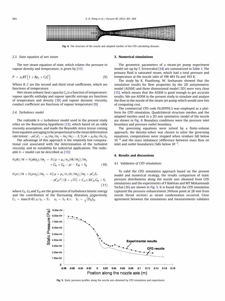
Fig. 4. The structure of the nozzle and adapted meshes of the CFD calculating domain.
X.-D. Wang et al. / Vacuum 86 (2012) 861e866864
2.3. State equation of wet steam
The wet steam equation of state, which relates the pressure tovapour density and temperature, is given by [11]:
P ¼ rvRT�1þ Brv þ Cr2v
�(9)
Where B, C are the second and third virial coefficients, which arefunctions of temperature.
Wet steam isobaric heat capacity Cp is a function of temperature;vapour specific enthalpy and vapour specific entropy are functionsof temperature and density [10] and vapour dynamic viscosity,conduct coefficient are functions of vapour temperature [9].
2.4. Turbulence model
The realizable ke3 turbulence model used in the present studyrelies on the Boussinesq hypothesis [12], which based on an eddyviscosity assumption, and made the Reynolds stress tensor comingfromequation averaging to beproportional to themeandeformationrate tensor:�ru0 iu0j ¼ mtðvui=vxj þ vuj=vxiÞ � 2=3ðrkþ mtdui=dxiÞdij
The advantage of this approach is the relatively low computa-tional cost associated with the determination of the turbulentviscosity, and its suitability for industrial applications. The realiz-able ke3 model can be described as [13]:
vðrkÞ=vt þ v�rkuj
�=vxj ¼ v
�ðmþ mt=skÞvk=vxj�
vxjþ Gk þ Gb � r3� YM þ Sk ð10Þ
vðr3Þ=vt þ v�r3uj
�=vxj ¼ v
�ðmþ mt=s3Þv3=vxj�
vxj þ rC1S3
� rC232=�kþ ffiffiffiffiffi
n3p �þ C133=kC33Gb þ S3
(11)
whereGk, Gb and YM are the generation of turbulence kinetic energyand the contribution of the fluctuating dilatation respectively.C1 ¼ maxð0:43;m=h1 þ 5Þ; h1 ¼ S1$k=3; S1 ¼
ffiffiffiffiffiffiffiffiffiffiffiffiffi2SijSij
q.
Fig. 5. Static pressure profiles along the nozzle axi
3. Numerical simulations
The geometric parameters of a steam-jet pump experimentmodel set-up by T. Sriveerakul [14] are summarized in Table 1. Theprimary fluid is saturated steam, which had a total pressure andtemperature at the nozzle inlet of 198 483 Pa and 393 K.
The study by K. Pianthong, W. Seehanam showed that thesimulation results for flow properties by the 2D axisymmetricmodel (ASXM) and three dimensional model (3D) were very close[15], which means that the ASXM is good enough to get accurateresults. We use ASXM in the present study to simulate and analysethe flow in the nozzle of the steam-jet pumpwhich would save lotsof computing cost.
The commercial CFD code FLUENT6.3 was employed as a plat-form for CFD simulation. Quadrilateral structure meshes and theadapted meshes used in a 2D axis symmetric model of the nozzleare shown in Fig. 4. Boundary conditions were the pressure inletboundary and pressure outlet boundary.
The governing equations were solved by a finite-volumeapproach; the density-solver was chosen to solve the governingequations, computations were stopped when residues fall below10�6 and the mass imbalance (difference between mass flow oninlet and outlet boundaries) falls below 10�7.
4. Results and discussions
4.1. Validation of CFD simulations
To valid the CFD simulation approach based on the presentmodel and numerical strategy, the results comparison of staticpressure distributions along the nozzle axis obtained from CFDsimulations and the experiments of F Bakhtan andMTMohammadiTochai [16] are shown in Fig. 5. It is found that the CFD simulationcaptured the pressure enhancement (Wilson point at 28 mm fromnozzle throat section) as steam condensation occurred. Closeagreement between the simulations and measurements validates
s obtained by CFD simulation and experiment.

Fig. 6. Static pressure profiles along the nozzle axis based on perfect gas and wet steam simulations.
X.-D. Wang et al. / Vacuum 86 (2012) 861e866 865
the mathematic models, and the following simulations werecarried out to simulate the flow characteristics in nozzle of thesteam-jet pump based on the geometric parameters in Table 1 andthe operating conditions mentioned in Section 3.
4.2. Wet steam flow characteristics in nozzle
4.2.1. Pressure distributions along nozzle axisThe pressure distributions along the nozzle axis are shown in
Fig. 6 based on wet steam model and perfect gas assumptionseparately. It is observed that there is a pressure sudden enhancingof wet steam to higher than that of perfect gas as condensationoccurred, and this differentia was kept to the outlet of the nozzle.
4.2.2. Mach number profiles in the nozzleThe Mach number profiles along the nozzle axis are shown in
Fig. 7 based on wet steam model and perfect gas assumptionseparately. It is found that there is a sudden drop of the Machnumber of wet steam to lower than that of perfect gas as
Fig. 7. Mach number profiles along the nozzle axis b
condensation occurred and this difference escalates from Wilsonpoint to the outlet of nozzle, and the maximum of the differentia isabout 10%. The droplets grown up with thermal-positive processfromWilson point to the outlet hinder the increase of flow velocityalong the nozzle axis.
4.2.3. Temperature profiles along nozzle axisThe temperature profiles along the nozzle axis are shown in
Fig. 8 based on wet steam model and perfect gas assumptionseparately. It is found that there is a temperature jumping of wetsteam due to a large thermal-positive induced by spontaneouscondensation. The condensation heat produced from the growingdroplets keeps the wet steam temperature much higher than thatof perfect gas.
The increased pressure and decreased velocity of steam super-sonic flow as spontaneous condensation occurred in the nozzlewould reduce the efficiency of nozzle, and the pumping perfor-mance of steam-jet vacuum pump would be re-evaluated forfurther study.
ased on perfect gas and wet steam simulations.
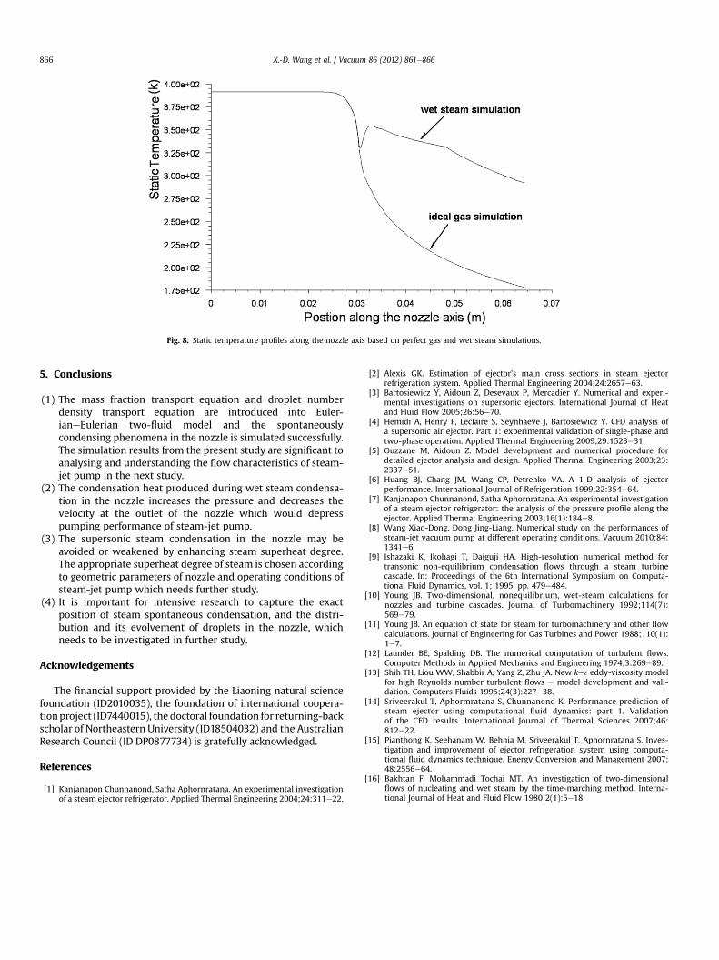
Fig. 8. Static temperature profiles along the nozzle axis based on perfect gas and wet steam simulations.
X.-D. Wang et al. / Vacuum 86 (2012) 861e866866
5. Conclusions
(1) The mass fraction transport equation and droplet numberdensity transport equation are introduced into Euler-ianeEulerian two-fluid model and the spontaneouslycondensing phenomena in the nozzle is simulated successfully.The simulation results from the present study are significant toanalysing and understanding the flow characteristics of steam-jet pump in the next study.
(2) The condensation heat produced during wet steam condensa-tion in the nozzle increases the pressure and decreases thevelocity at the outlet of the nozzle which would depresspumping performance of steam-jet pump.
(3) The supersonic steam condensation in the nozzle may beavoided or weakened by enhancing steam superheat degree.The appropriate superheat degree of steam is chosen accordingto geometric parameters of nozzle and operating conditions ofsteam-jet pump which needs further study.
(4) It is important for intensive research to capture the exactposition of steam spontaneous condensation, and the distri-bution and its evolvement of droplets in the nozzle, whichneeds to be investigated in further study.
Acknowledgements
The financial support provided by the Liaoning natural sciencefoundation (ID2010035), the foundation of international coopera-tionproject (ID7440015), the doctoral foundation for returning-backscholar of Northeastern University (ID18504032) and the AustralianResearch Council (ID DP0877734) is gratefully acknowledged.
References
[1] Kanjanapon Chunnanond, Satha Aphornratana. An experimental investigationof a steam ejector refrigerator. Applied Thermal Engineering 2004;24:311e22.
[2] Alexis GK. Estimation of ejector’s main cross sections in steam ejectorrefrigeration system. Applied Thermal Engineering 2004;24:2657e63.
[3] Bartosiewicz Y, Aidoun Z, Desevaux P, Mercadier Y. Numerical and experi-mental investigations on supersonic ejectors. International Journal of Heatand Fluid Flow 2005;26:56e70.
[4] Hemidi A, Henry F, Leclaire S, Seynhaeve J, Bartosiewicz Y. CFD analysis ofa supersonic air ejector. Part 1: experimental validation of single-phase andtwo-phase operation. Applied Thermal Engineering 2009;29:1523e31.
[5] Ouzzane M, Aidoun Z. Model development and numerical procedure fordetailed ejector analysis and design. Applied Thermal Engineering 2003;23:2337e51.
[6] Huang BJ, Chang JM, Wang CP, Petrenko VA. A 1-D analysis of ejectorperformance. International Journal of Refrigeration 1999;22:354e64.
[7] Kanjanapon Chunnanond, Satha Aphornratana. An experimental investigationof a steam ejector refrigerator: the analysis of the pressure profile along theejector. Applied Thermal Engineering 2003;16(1):184e8.
[8] Wang Xiao-Dong, Dong Jing-Liang. Numerical study on the performances ofsteam-jet vacuum pump at different operating conditions. Vacuum 2010;84:1341e6.
[9] Ishazaki K, Ikohagi T, Daiguji HA. High-resolution numerical method fortransonic non-equilibrium condensation flows through a steam turbinecascade. In: Proceedings of the 6th International Symposium on Computa-tional Fluid Dynamics, vol. 1; 1995. pp. 479e484.
[10] Young JB. Two-dimensional, nonequilibrium, wet-steam calculations fornozzles and turbine cascades. Journal of Turbomachinery 1992;114(7):569e79.
[11] Young JB. An equation of state for steam for turbomachinery and other flowcalculations. Journal of Engineering for Gas Turbines and Power 1988;110(1):1e7.
[12] Launder BE, Spalding DB. The numerical computation of turbulent flows.Computer Methods in Applied Mechanics and Engineering 1974;3:269e89.
[13] Shih TH, Liou WW, Shabbir A, Yang Z, Zhu JA. New ke3 eddy-viscosity modelfor high Reynolds number turbulent flows e model development and vali-dation. Computers Fluids 1995;24(3):227e38.
[14] Sriveerakul T, Aphormratana S, Chunnanond K. Performance prediction ofsteam ejector using computational fluid dynamics: part 1. Validationof the CFD results. International Journal of Thermal Sciences 2007;46:812e22.
[15] Pianthong K, Seehanam W, Behnia M, Sriveerakul T, Aphornratana S. Inves-tigation and improvement of ejector refrigeration system using computa-tional fluid dynamics technique. Energy Conversion and Management 2007;48:2556e64.
[16] Bakhtan F, Mohammadi Tochai MT. An investigation of two-dimensionalflows of nucleating and wet steam by the time-marching method. Interna-tional Journal of Heat and Fluid Flow 1980;2(1):5e18.
Related Documents