Driving large magnetic Reynolds number flow in highly ionized, unmagnetized plasmas D. B. Weisberg, E. Peterson, J. Milhone, D. Endrizzi, C. Cooper, V. Désangles, I. Khalzov, R. Siller, and C. B. Forest Citation: Physics of Plasmas 24, 056502 (2017); doi: 10.1063/1.4978889 View online: https://doi.org/10.1063/1.4978889 View Table of Contents: http://aip.scitation.org/toc/php/24/5 Published by the American Institute of Physics Articles you may be interested in Analysis of self-consistent nonlinear wave-particle interactions of whistler waves in laboratory and space plasmas Physics of Plasmas 24, 056501 (2017); 10.1063/1.4977539 Electron holes in phase space: What they are and why they matter Physics of Plasmas 24, 055601 (2017); 10.1063/1.4976854 Structure and structure-preserving algorithms for plasma physics Physics of Plasmas 24, 055502 (2017); 10.1063/1.4982054 Are two plasma equilibrium states possible when the emission coefficient exceeds unity? Physics of Plasmas 24, 057101 (2017); 10.1063/1.4976856 An extended study of the ignition design space of magnetized target fusion Physics of Plasmas 24, 055602 (2017); 10.1063/1.4977538 Plasma-based water purification: Challenges and prospects for the future Physics of Plasmas 24, 055501 (2017); 10.1063/1.4977921

Welcome message from author
This document is posted to help you gain knowledge. Please leave a comment to let me know what you think about it! Share it to your friends and learn new things together.
Transcript

Driving large magnetic Reynolds number flow in highly ionized, unmagnetizedplasmasD. B. Weisberg, E. Peterson, J. Milhone, D. Endrizzi, C. Cooper, V. Désangles, I. Khalzov, R. Siller, and C. B.Forest
Citation: Physics of Plasmas 24, 056502 (2017); doi: 10.1063/1.4978889View online: https://doi.org/10.1063/1.4978889View Table of Contents: http://aip.scitation.org/toc/php/24/5Published by the American Institute of Physics
Articles you may be interested in Analysis of self-consistent nonlinear wave-particle interactions of whistler waves in laboratory and spaceplasmasPhysics of Plasmas 24, 056501 (2017); 10.1063/1.4977539
Electron holes in phase space: What they are and why they matterPhysics of Plasmas 24, 055601 (2017); 10.1063/1.4976854
Structure and structure-preserving algorithms for plasma physicsPhysics of Plasmas 24, 055502 (2017); 10.1063/1.4982054
Are two plasma equilibrium states possible when the emission coefficient exceeds unity?Physics of Plasmas 24, 057101 (2017); 10.1063/1.4976856
An extended study of the ignition design space of magnetized target fusionPhysics of Plasmas 24, 055602 (2017); 10.1063/1.4977538
Plasma-based water purification: Challenges and prospects for the futurePhysics of Plasmas 24, 055501 (2017); 10.1063/1.4977921

Driving large magnetic Reynolds number flow in highly ionized,unmagnetized plasmas
D. B. Weisberg,1,2,a),b) E. Peterson,2 J. Milhone,2 D. Endrizzi,2 C. Cooper,2,3 V. D�esangles,4
I. Khalzov,2,5 R. Siller,2 and C. B. Forest21Oak Ridge Associated Universities, Oak Ridge, Tennessee 37830, USA2Department of Physics, University of Wisconsin, Madison, Wisconsin 53706, USA3Lawrence Livermore National Laboratory, Livermore, California 94550, USA4Univ Lyon, Ens de Lyon, Laboratoire de Physique, F-69342 Lyon, France5Kurchatov Institute, Moscow 123098, Russia
(Received 11 November 2016; accepted 28 February 2017; published online 22 March 2017)
Electrically driven, unmagnetized plasma flows have been generated in the Madison plasma
dynamo experiment with magnetic Reynolds numbers exceeding the predicted Rmcrit¼ 200
threshold for flow-driven MHD instability excitation. The plasma flow is driven using ten thermally
emissive lanthanum hexaboride cathodes which generate a J � B torque in helium and argon plas-
mas. Detailed Mach probe measurements of plasma velocity for two flow topologies are presented:
edge-localized drive using the multi-cusp boundary field and volumetric drive using an axial
Helmholtz field. Radial velocity profiles show that the edge-driven flow is established via ion vis-
cosity but is limited by a volumetric neutral drag force, and measurements of velocity shear com-
pare favorably to the Braginskii transport theory. Volumetric flow drive is shown to produce larger
velocity shear and has the correct flow profile for studying the magnetorotational instability.
Published by AIP Publishing. [http://dx.doi.org/10.1063/1.4978889]
I. INTRODUCTION
MHD fluid dynamics experiments necessarily rely on
some mechanisms for stirring flows in a controlled manner.
Techniques for flow drive range from highly localized
momentum injection via mechanical pumping or propulsion
to global body forcing via electromagnetic drives.1 In addi-
tion, rotating tanks can be used to impose a boundary condi-
tion on an axisymmetric flow that then viscously couples to
the rest of the fluid.2 However, the topic of plasma hydrody-
namics is relatively unexplored, as the regime in which plas-
mas are flow-dominated and yet highly conducting is a
major experimental frontier. The dynamics in such a system
are primarily governed by hydrodynamics, with the onset of
MHD physics only in the case where small magnetic diffu-
sivity and large Alfv�en Mach flow result in the growth of a
flow-driven MHD instability and the magnetization of the
system.
A particularly intriguing application of stirred plasmas
is the investigation of astrophysical phenomena like the
dynamo effect and the magnetorotational instability (MRI).
Laboratory experiments have long been seen as a valuable
way to gain an empirical understanding of these flow-driven
MHD instabilities. The dynamo effect3 is the mechanism
thought to be responsible for the generation of magnetic
energy in planetary cores, stellar convection zones, and the
interstellar medium, while the MRI is an MHD instability
that accelerates the accretion of matter in weakly magnetized
astrophysical disks.4 Both theories are well established both
analytically and in numerical simulations,5–8 but lack
experimental evidence to rigorously confirm these underly-
ing physical mechanisms. Previous experiments have used
both liquid metal9–13 and plasma14 as the conducting fluid
for achieving the large dimensionless parameters necessary
for exciting these instabilities, with magnetic bucket plasma
confinement devices succeeding in producing the largest
magnetic Reynolds number (Rm) flows to date. However,
these experiments have fallen short of achieving the critical
Rm required for positive instability growth rates as suggested
by numerical simulations of both the dynamo15,16 and the
MRI.17 The Madison plasma dynamo experiment (MPDX) is
a new magnetic ring cusp device18 that has been constructed
with the goal of reaching and surpassing critical Rm thresh-
olds for instability excitation.
In order to observe the dynamo or the MRI in the labora-
tory, a plasma experiment must meet certain criteria, usually
expressed in dimensionless terms. The confined plasma must
have a large amount of kinetic energy stored in fluid flows,
but these flows cannot be initially magnetized; otherwise, the
Lorentz force will modify the global flow geometry and pre-
vent instability excitation. The confined plasma must also be
highly conducting so that plasma flows can easily advect the
magnetic field without appreciable magnetic diffusion.
These conditions are expressed using the Reynolds number
Re, the magnetic Reynolds number Rm, and the Alfv�enic
Mach number Ma
Re ¼ V0R0=� ¼ 0:52n18
ffiffiffilp
kZ4Vkm=sRm
T5=2i;eV
; (1)
Rm ¼ l0rV0R0 ¼ 12:2T
3=2e;eVVkm=sRm
kZ; (2)
Note: Paper BI3 4, Bull. Am. Phys. Soc. 61, 23 (2016).a)Invited speaker.b)Electronic mail: [email protected]
1070-664X/2017/24(5)/056502/10/$30.00 Published by AIP Publishing.24, 056502-1
PHYSICS OF PLASMAS 24, 056502 (2017)
Ma ¼ V0=VA ¼ 0:46
ffiffiffiffiffiffiffiffiffin18lp
Vkm=s
BG; (3)
where V0 and R0 are the characteristic velocity and length
scales of the experiment, � is the kinematic viscosity, and ris the resistivity. These terms are defined above using plasma
transport parameters,19 where n18 is the plasma density in
units of 1018 m–3, Te and Ti are in electron volts, and l is the
ion species atomic weight in amu. Z and k are the ion charge
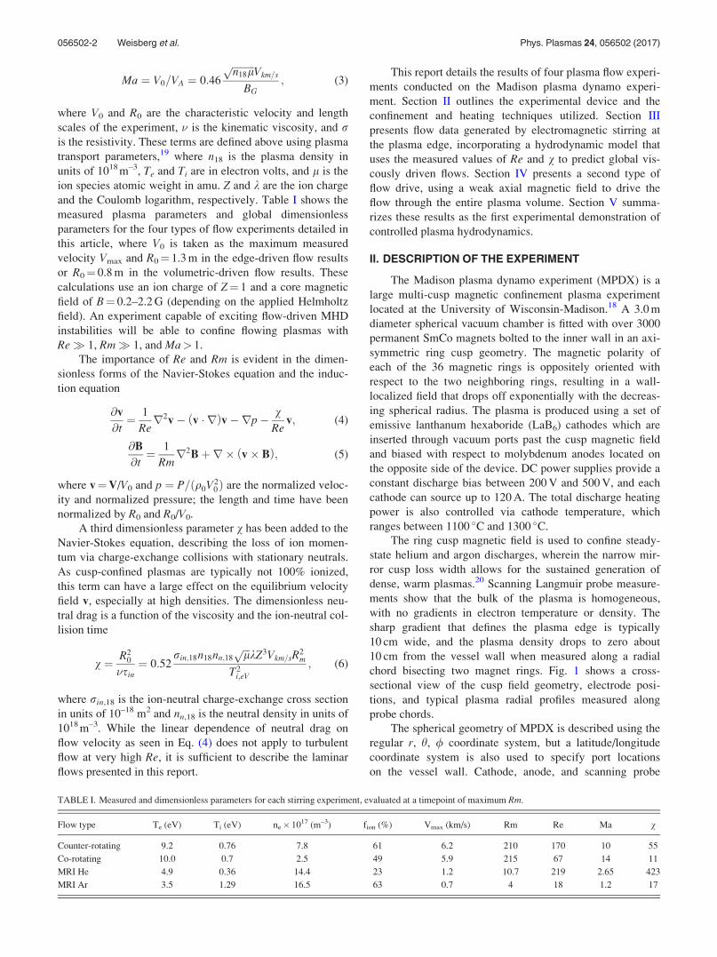
and the Coulomb logarithm, respectively. Table I shows the
measured plasma parameters and global dimensionless
parameters for the four types of flow experiments detailed in
this article, where V0 is taken as the maximum measured
velocity Vmax and R0¼ 1.3 m in the edge-driven flow results
or R0¼ 0.8 m in the volumetric-driven flow results. These
calculations use an ion charge of Z¼ 1 and a core magnetic
field of B¼ 0.2–2.2 G (depending on the applied Helmholtz
field). An experiment capable of exciting flow-driven MHD
instabilities will be able to confine flowing plasmas with
Re� 1, Rm� 1, and Ma> 1.
The importance of Re and Rm is evident in the dimen-
sionless forms of the Navier-Stokes equation and the induc-
tion equation
@v
@t¼ 1
Rer2v� v � rð Þv�rp� v
Rev; (4)
@B
@t¼ 1
Rmr2Bþr� v� Bð Þ; (5)
where v¼V/V0 and p ¼ P=ðq0V20Þ are the normalized veloc-
ity and normalized pressure; the length and time have been
normalized by R0 and R0/V0.
A third dimensionless parameter v has been added to the
Navier-Stokes equation, describing the loss of ion momen-
tum via charge-exchange collisions with stationary neutrals.
As cusp-confined plasmas are typically not 100% ionized,
this term can have a large effect on the equilibrium velocity
field v, especially at high densities. The dimensionless neu-
tral drag is a function of the viscosity and the ion-neutral col-
lision time
v ¼ R20
�sin¼ 0:52
rin;18n18nn;18ffiffiffilp
kZ3Vkm=sR2m
T2i;eV
; (6)
where rin,18 is the ion-neutral charge-exchange cross section
in units of 10–18 m2 and nn,18 is the neutral density in units of
1018 m–3. While the linear dependence of neutral drag on
flow velocity as seen in Eq. (4) does not apply to turbulent
flow at very high Re, it is sufficient to describe the laminar
flows presented in this report.
This report details the results of four plasma flow experi-
ments conducted on the Madison plasma dynamo experi-
ment. Section II outlines the experimental device and the
confinement and heating techniques utilized. Section III
presents flow data generated by electromagnetic stirring at
the plasma edge, incorporating a hydrodynamic model that
uses the measured values of Re and v to predict global vis-
cously driven flows. Section IV presents a second type of
flow drive, using a weak axial magnetic field to drive the
flow through the entire plasma volume. Section V summa-
rizes these results as the first experimental demonstration of
controlled plasma hydrodynamics.
II. DESCRIPTION OF THE EXPERIMENT
The Madison plasma dynamo experiment (MPDX) is a
large multi-cusp magnetic confinement plasma experiment
located at the University of Wisconsin-Madison.18 A 3.0 m
diameter spherical vacuum chamber is fitted with over 3000
permanent SmCo magnets bolted to the inner wall in an axi-
symmetric ring cusp geometry. The magnetic polarity of
each of the 36 magnetic rings is oppositely oriented with
respect to the two neighboring rings, resulting in a wall-
localized field that drops off exponentially with the decreas-
ing spherical radius. The plasma is produced using a set of
emissive lanthanum hexaboride (LaB6) cathodes which are
inserted through vacuum ports past the cusp magnetic field
and biased with respect to molybdenum anodes located on
the opposite side of the device. DC power supplies provide a
constant discharge bias between 200 V and 500 V, and each
cathode can source up to 120 A. The total discharge heating
power is also controlled via cathode temperature, which
ranges between 1100 �C and 1300 �C.
The ring cusp magnetic field is used to confine steady-
state helium and argon discharges, wherein the narrow mir-
ror cusp loss width allows for the sustained generation of
dense, warm plasmas.20 Scanning Langmuir probe measure-
ments show that the bulk of the plasma is homogeneous,
with no gradients in electron temperature or density. The
sharp gradient that defines the plasma edge is typically
10 cm wide, and the plasma density drops to zero about
10 cm from the vessel wall when measured along a radial
chord bisecting two magnet rings. Fig. 1 shows a cross-
sectional view of the cusp field geometry, electrode posi-
tions, and typical plasma radial profiles measured along
probe chords.
The spherical geometry of MPDX is described using the
regular r, h, / coordinate system, but a latitude/longitude
coordinate system is also used to specify port locations
on the vessel wall. Cathode, anode, and scanning probe
TABLE I. Measured and dimensionless parameters for each stirring experiment, evaluated at a timepoint of maximum Rm.
Flow type Te (eV) Ti (eV) ne� 1017 (m–3) fion (%) Vmax (km/s) Rm Re Ma v
Counter-rotating 9.2 0.76 7.8 61 6.2 210 170 10 55
Co-rotating 10.0 0.7 2.5 49 5.9 215 67 14 11
MRI He 4.9 0.36 14.4 23 1.2 10.7 219 2.65 423
MRI Ar 3.5 1.29 16.5 63 0.7 4 18 1.2 17
056502-2 Weisberg et al. Phys. Plasmas 24, 056502 (2017)

positions in this report are given using this system, where the
north pole (þ90, h¼ 0) is at the top of the poloidal cross-
section in Fig. 1 and the south pole (–90, h¼ p) is at the bot-
tom. Vacuum ports are located at multiples of 5� (90, 85, and
80, excluding the equator) with magnet rings offset by 2.5�
(87.5, 82.5, and 77.5).
The scanning probe array installed on MPDX consists of
up to nine combination Langmuir/Mach probes. Each probe
tip contains four planar Mach faces and a Langmuir wire tip
so that the local electron temperature and density are mea-
sured along with up to two components of the local ion flow
Mach number. Thus, each probe measures the absolute ion
flow velocity in two directions: the h (north-south) and /(east-west) components of the plasma flow. In order to obtain
a global picture of the plasma flow, velocity probes are distrib-
uted between the north pole and the south pole of the vacuum
vessel and are scanned between the plasma edge (r� 140 cm)
and their maximum insertion depth of r¼ 90 cm.
In addition to the velocity probe array, several non-
invasive diagnostic systems are used to measure core plasma
parameters. A mm-wave heterodyne interferometer is used
to measure the line-averaged electron density, a Fabry-Perot
interferometer measures the core ion temperature, and a
pyrometric bolometer measures the radiated power at the
vessel wall. The neutral pressure is measured at the vessel
wall with two cold-cathode vacuum gauges, and an array of
survey spectrometers measures the radial neutral density pro-
file via optical emission spectroscopy.
III. EDGE-DRIVEN FLOW
The first method of injecting momentum into the bulk
unmagnetized plasma uses the application of a J � B torque
at the plasma’s magnetized edge, as shown in Fig. 1(c). The
emissive LaB6 cathodes are retracted to a radial position
closer to the vessel wall (130< r< 135 cm) where the mag-
netic cusp field is approx. 20 G, while the molybdenum ano-
des are inserted well beyond the cusp field (r� 115 cm)
where the uncorrected component of Earth’s field is less than
0.2 G. The bulk unmagnetized plasma is thus maintained at a
uniform electric potential close to the grounded anodes, and
all current drawn from the cathodes is directed radially.
Because the cusp field is aligned in the theta direction at the
cathode locations, the resulting J � B torque due to the dis-
charged current is in the phi direction. This spins up the edge
of the plasma in the direction determined by the polarity of
the cusp field: at co-latitudes of 685, 675, 615, and 65,
the torque is in the �/̂ direction, while at co-latitudes of
680, 670, 620, and 610, the torque is in the þ/̂ direction.
Momentum is transported from the spinning edge into
the core via ion-ion viscosity but is lost to charge-exchange
collisions with unconfined neutrals. A simple 1D form of the
momentum equation is
@v/
@t¼ 1
mnJr � Bhð Þ/ �
v/
sinþ �ii r2v½ �; (7)
where the J � B torque is only non-zero at the plasma edge.
A 2D hydrodynamic numerical code has been developed16 to
solve the axisymmetric version of this momentum transport
equation, in which the toroidal velocity boundary condition
at the plasma edge v/ðr ¼ R; hÞ is an arbitrary function of
the polar angle. The transport of momentum inward is calcu-
lated using a global value of Re, where the classical unmag-
netized plasma ion viscosity is calculated using measured
density and ion temperature
� ¼ 0:96v2tisii /
T5=2i
nffiffiffilp ; (8)
where the neutral drag term is calculated using the 1D neu-
tral diffusion theory benchmarked against optical emission
spectroscopy measurements. This transport model predicts
the neutral burn-out in the plasma core
nn rð Þ ¼ Asinh r=kmf p
� �r=kmf p
; (9)
kmf p ¼ vth;n=ð�iz þ �cxÞ; (10)
A ¼ nnRR=kmf p
sinh R=kmf p
� � ; (11)
FIG. 1. Cross-sectional schematic of
the MPDX vessel. (a) The ring cusp
magnetic field is axisymmetric about
the z-axis, and electrodes and probes
are inserted through ports between
magnet rings. (b) The cusp field
decreases exponentially with the radius
and confines a homogeneous plasma.
(c) Edge toroidal flow is driven by the
J � B torque near retracted cathodes
(gold), where the current is sourced by
inserted anodes (grey).
056502-3 Weisberg et al. Phys. Plasmas 24, 056502 (2017)

where kmfp is the total neutral mean free path for ionization
and charge-exchange collisions, vth,n is the neutral thermal
velocity (based on room temperature Tn¼ 0.025 eV), and nnR
is the neutral density at the wall (r¼R). Thus, the amount of
neutral burn-out is encoded in the radial profile of the dimen-
sionless neutral drag v. The details of this hydrodynamic
solver are discussed further in the Appendix.
The strategic placement of cathodes allows the edge
plasma flow to be arbitrarily controlled and permits the reali-
zation of a wide possibility of flow geometries. The edge
flow is primarily a function of cathode latitudinal location
and cathode discharge power, as well as the strength of the
edge field at the cathode radial position. The two main flow
geometries established using this technique are (a) counter-
rotating hemispheres and (b) co-rotating hemispheres. These
correspond to the T1 and T2 toroidal flow harmonics in the
spherical expansions of Bullard and Gellman,21 and at lower
enough viscosity, both result in one poloidal circulation cell
in each hemisphere. The only hardware limitation on the
edge rotation profile is the presence of Helmholtz coils
which block cathode installation at latitudes of 35� and 30�
in both the northern and southern hemispheres. This explains
the conspicuous gap in cathode placement evident in the
experimental setups presented in Secs. III A and III B.
A. Counter-rotating hemispheres
Resistive MDH simulations have shown that counter-
rotating hemispheres in a sphere generate a laminar flow
geometry that is capable of exciting the dynamo instability.16
In a spherical analog to the von-Karman flow, the oppositely
directed toroidal flow in the north and south hemispheres can
drive two poloidal flow cells, with a strong radial outflow
from the equator to the poles and a weaker inflow at the
equatorial plane. This so-called “two-vortex” flow can, at
large enough Rm (�300), advect and amplify a weak trans-
verse seed magnetic field through a stretch-twist-fold mecha-
nism. The transition to positive magnetic growth rates has
been shown to be very sensitive to details of the flow geome-
try, and so the well-established flow control is important in a
dynamo experiment.
To drive the counter-rotating flow in MPDX, 8 cathodes
were distributed at mid-to-high latitudes in both the north
and south hemispheres and were retracted into the cusp, and
so the LaB6 spanned the radial interval 130< r< 135 cm.
Two additional cathodes near the equator were not retracted
and were used only to provide additional heating power
without affecting the edge flow. Nine velocity probes were
scanned between r¼ 90 cm and r¼ 130 cm, and their elec-
tron density measurements in the plasma core were cali-
brated to the line-averaged mm-wave interferometer
measurements.
Fig. 2 shows the results from the counter-rotating experi-
ment, including the results of 2D hydrodynamic modeling.
The maximum flow velocity was measured to be 6 km/s,
resulting in dimensionless parameters of Re¼ 170, Rm¼ 210,
and vwall¼ 55. The results of the hydrodynamic simulations
compare favorably with velocity probe measurements in
FIG. 2. Counter-rotating flow measurements in helium. (a) Global plasma parameters; error bars indicate the shot-to-shot variation. (b) Globally averaged
radial profiles from scanning Langmuir probes. (c) Electrode and probe placement with the modeled flow: poloidal flow contours and streamlines are shown on
left and toroidal flow contours on right. (d) Velocity probe radial profiles, showing counter-rotating hemispheres. Colors correspond to probe positions in (c),
and the solid lines correspond to the modeled flow.
056502-4 Weisberg et al. Phys. Plasmas 24, 056502 (2017)

MPDX. The two hemispheres are clearly rotating in opposite
directions, with the edge momentum transported inward at
rates predicted by classical viscous diffusion. At this moderate
ionization fraction of �60%, the neutral drag is a significant
factor in the momentum transport equation, limiting toroidal
flow penetration and forcing flow below measurable levels by
r¼ 90 cm. In contrast to the large toroidal flows, poloidal
velocity flows are too slow to be resolved above the �1 km/s
probe error; this matches the simulated vh values which are
less than 500 m/s throughout the spherical volume.
B. Co-rotating hemispheres
A second stirring geometry was tested in MPDX in
which all cathodes were installed so as to drive the flow in
the same (toroidal) direction. This co-rotating flow is
designed to be a simple model of the differential flow
observed in the solar convective zone, where the equatorial
period of 25 days is much shorter than the polar period of 34
days.22 For this experiment, ten cathodes were distributed
between the north and south poles and retracted into the cusp
field to 130< r< 135 cm. Unlike the counter-rotating flow
experiment, there is no velocity null between the two hemi-
spheres, and so stirring cathodes can be placed at the equator
and at mid-to-high latitudes. Five velocity probes were
scanned, with four of them located in the same magnet ring
as a stirring cathode.
Fig. 3 shows the results of the co-rotating experiment
and their comparison to the hydrodynamic model results.
While these helium plasmas had a smaller ionization fraction
in comparison to the counter-rotating experiment, the
depressed values of the core electron density and neutral fill
pressure resulted in lowered dimensionless parameters of
Re¼ 67 and v¼ 11. However, the magnetic Reynolds num-
ber was still quite high at Rm¼ 215 due to comparable meas-
urements of Te and maximum velocity. The Langmuir probe
radial profiles in Fig. 3(b) once again indicate a homoge-
neous core, albeit with a slight increase in electron tempera-
ture and density at the radial position of the LaB6 cathodes.
This local increase is frequently observed in magnet rings
with retracted stirring cathodes and is presumably present in
the counter-rotating experiment as well. It is more evident
here only due to the increased number of probes in cathode
rings. Thus, the inputs to the hydrodynamic simulations for
both edge-drive experiments were calculated using
R¼ 130 cm, taking into account the observation that the core
volume of homogeneous viscosity and Re extends out only
as far as the volume of constant ne is concerned.
The measured velocity profiles in Fig. 3(d) show a uni-
form rotation direction with relatively small gradients and a
non-zero flow in the plasma core. This is partially attribut-
able to the lack of a velocity null near the equatorial plane,
which in the counter-rotating case served to further suppress
the flow far from the vessel wall. In addition, the smaller val-
ues of Re and v here increased the radial momentum flux and
decreased the loss of momentum to charge-exchange colli-
sions. A downside to decreased Re is the decreased poloidal
flow, and the modeled flows agree with probe measurements
of vh insofar as both are below the Mach probe noise level.
The measured velocity gradients are a poorer match to simu-
lation results, at least at radial positions closer to the edge
cusp field; this may be due to a lack of spherical symmetry
in neutral out-gassing or some other transport-induced local
change in neutral drag.
FIG. 3. Co-rotating flow measurements in helium. (a) Global plasma parameters; error bars indicate the shot-to-shot variation. (b) Globally averaged radial
profiles from scanning Langmuir probes. (c) Electrode and probe placement with the modeled flow: poloidal flow contours and streamlines are shown on left
and toroidal flow contours on right. (d) Velocity probe radial profiles, showing co-rotating hemispheres. Colors correspond to probe positions in (c), and the
solid lines correspond to the modeled flow.
056502-5 Weisberg et al. Phys. Plasmas 24, 056502 (2017)
IV. VOLUMETRIC-DRIVEN FLOW
The second method of stirring MPDX plasmas is
designed to generate flow profiles appropriate for the study
of the MRI. In astrophysical accretion disks, the plasma in
the disk itself follows a Keplerian angular velocity profile23
XðrÞ ¼ffiffiffiffiffiffiffiffiffiffiffiffiffiffiGM=r3
p: (12)
Observations of disk luminosities indicate an accretion
rate that far exceeds the expected rate due to classical vis-
cous momentum transport, and the MRI acts to facilitate tur-
bulent transport through an MHD instability that arises from
the combination of a weak seed magnetic field and shear
flow. In order to observe this effect in the laboratory, other
sources of plasma turbulence must be avoided while main-
taining the correct direction of flow shear. The MRI is desta-
bilized by an angular velocity profile that decreases with the
radius, while hydrodynamic turbulence is avoided if the
angular momentum increases with the radius2
dXdr
< 0;d r2Xð Þ
dr> 0; (13)
where r in this section refers to the cylindrical radius.
This velocity profile is opposite to that of the edge-
driven flows described in Section III and requires a different
flow drive technique. Instead of limiting the J � B torque to
the magnetized edge region of MPDX plasmas, a uniform
axial magnetic field is externally applied using the 4.07 m
diameter Helmholtz coil set. The discharge current that flows
in the cylindrical radial direction will generate a J � B tor-
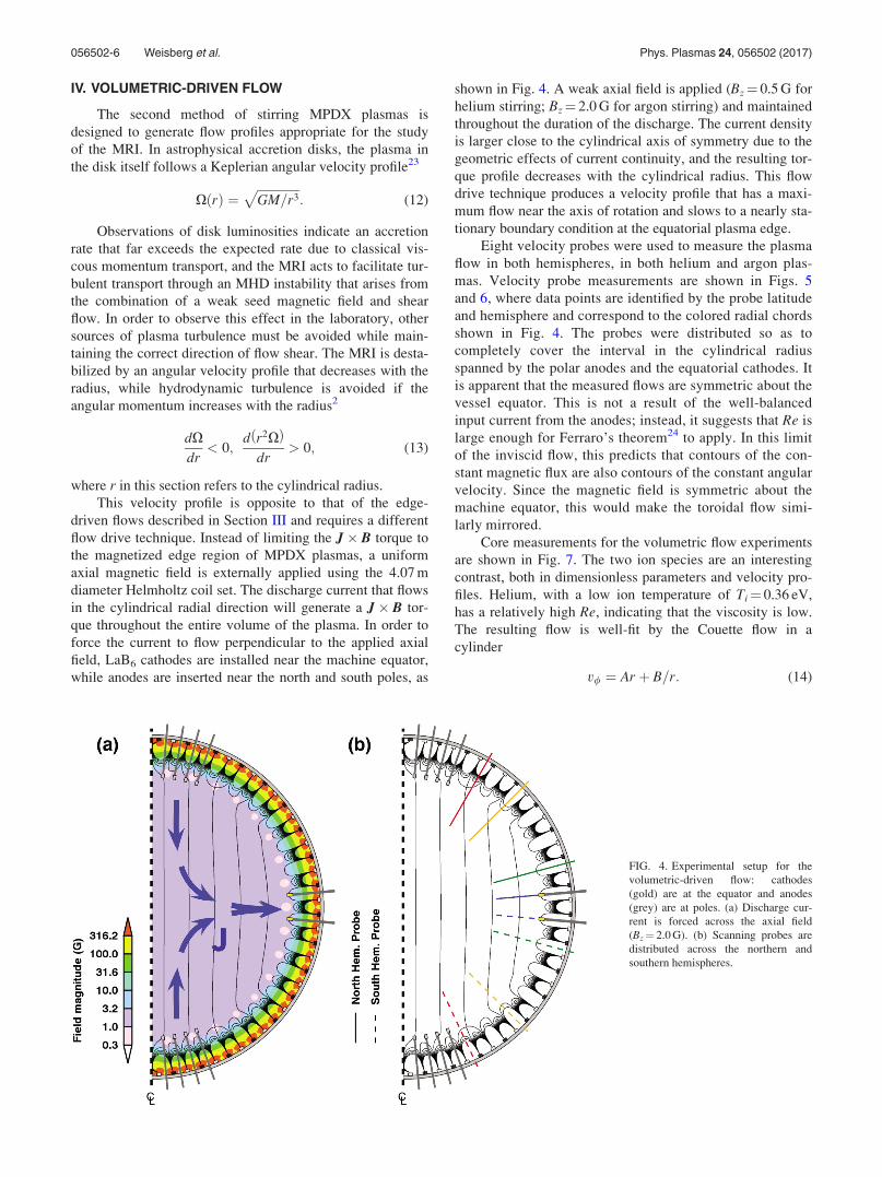
que throughout the entire volume of the plasma. In order to
force the current to flow perpendicular to the applied axial
field, LaB6 cathodes are installed near the machine equator,
while anodes are inserted near the north and south poles, as
shown in Fig. 4. A weak axial field is applied (Bz¼ 0.5 G for
helium stirring; Bz¼ 2.0 G for argon stirring) and maintained
throughout the duration of the discharge. The current density
is larger close to the cylindrical axis of symmetry due to the
geometric effects of current continuity, and the resulting tor-
que profile decreases with the cylindrical radius. This flow
drive technique produces a velocity profile that has a maxi-
mum flow near the axis of rotation and slows to a nearly sta-
tionary boundary condition at the equatorial plasma edge.
Eight velocity probes were used to measure the plasma
flow in both hemispheres, in both helium and argon plas-
mas. Velocity probe measurements are shown in Figs. 5
and 6, where data points are identified by the probe latitude
and hemisphere and correspond to the colored radial chords
shown in Fig. 4. The probes were distributed so as to
completely cover the interval in the cylindrical radius
spanned by the polar anodes and the equatorial cathodes. It
is apparent that the measured flows are symmetric about the
vessel equator. This is not a result of the well-balanced
input current from the anodes; instead, it suggests that Re is
large enough for Ferraro’s theorem24 to apply. In this limit
of the inviscid flow, this predicts that contours of the con-
stant magnetic flux are also contours of the constant angular
velocity. Since the magnetic field is symmetric about the
machine equator, this would make the toroidal flow simi-
larly mirrored.
Core measurements for the volumetric flow experiments
are shown in Fig. 7. The two ion species are an interesting
contrast, both in dimensionless parameters and velocity pro-
files. Helium, with a low ion temperature of Ti¼ 0.36 eV,
has a relatively high Re, indicating that the viscosity is low.
The resulting flow is well-fit by the Couette flow in a
cylinder
v/ ¼ Ar þ B=r: (14)
FIG. 4. Experimental setup for the
volumetric-driven flow: cathodes
(gold) are at the equator and anodes
(grey) are at poles. (a) Discharge cur-
rent is forced across the axial field
(Bz¼ 2.0 G). (b) Scanning probes are
distributed across the northern and
southern hemispheres.
056502-6 Weisberg et al. Phys. Plasmas 24, 056502 (2017)

The inner region is marginally stable to the hydrody-
namic instability, but the radial gradient in angular momen-
tum becomes negative outside of r� 90 cm. This indicates
that the MRI may be active in the inner core of the rotating
plasma column and could even be modifying the equilibrium
velocity profile to push the outer core into a hydrodynami-
cally unstable regime. A dearth of modeling on this flow
drive geometry limits the physical intuition that can be
applied to these measurements, but in general, the data show
promise for future MRI studies in helium plasmas. The
Alfv�en Mach number Ma is consistently larger than unity,
and Re is large, indicating that the axial field is weak com-
pared to the generated flows and that the viscosity is negligi-
ble. Both of these conditions are requirements for the
measurement of an MRI mode that is strong enough to over-
come both viscous damping and Lorentz force saturation.
Such a saturated mode could be detected by measuring the
turbulent spectrum of the small-scale radial magnetic field in
the plasma core: a marked increase in turbulent magnetic
energy at a specific threshold Rm would be strong evidence
for the onset of an inductive instability. These in-situ meas-
urements are currently outside the capability of the MPDX
diagnostics, but an improvement in magnetic probe sensitiv-
ity is a high priority for future research.
In contrast to the helium MRI data, measurements in
argon plasmas have a much smaller Re due in part to the
higher ion temperature of Ti¼ 1.29 eV. This plasma flow is
more viscous, and so momentum diffusion plays a larger role in
limiting velocity gradients. The measurements show a flat veloc-
ity profile out to r¼ 90 cm, which is not well-fit by a Couette-
driven flow profile. The inner flow is linearly stable to hydrody-
namic instability, but the outer core of the rotating plasma
column should undergo a transition to non-axisymmetric modes
due to the Rayleigh criterion.
It should be emphasized that no velocity fluctuations
have been measured over the course of all MPDX flow
experiments. The lack of fluid instability signatures in the
Mach probe data points to the possible role of neutrals and
viscosity in damping fluid turbulence. In the case of the volu-
metric helium flow, there is minimal neutral burn-out in the
plasma core, leading to significant neutral drag on the flow-
ing ions. The momentum source term corresponding to the
global J � B torque is large compared to the neutral drag,
but smaller-scale turbulent fluctuations could be more sus-
ceptible to damping. A similar argument can be applied to
the volumetric argon flow which, while being highly ionized,
has a small Re� 18. The larger viscosity could serve to
increase the threshold angular momentum gradient for the
transition to hydrodynamic turbulence, permitting the
observed profiles to exist in a laminar state.
V. CONCLUSIONS
A novel multi-cusp plasma device was built to investi-
gate flow-driven MHD instabilities, and initial experiments
have been successful at generating high Rm plasma flows.
FIG. 5. Velocity probe measurements of the toroidal flow in the helium
plasma.FIG. 6. Velocity probe measurements of the toroidal flow in the argon
plasma.
056502-7 Weisberg et al. Phys. Plasmas 24, 056502 (2017)

Plasma ionization fractions are in excess of 50% in both
helium and argon discharges due in part to the improved con-
finement afforded by the axisymmetric multi-cusp geometry.
The recent innovations both in permanent magnet energy
density and LaB6 cathode fabrication allow MPDX plasmas
to occupy new regions in the Re, Rm parameter space, out-
performing the previous magnetic bucket devices and for the
first time reaching conditions amenable to generation of the
dynamo and MRI.
The various flow geometries presented here are designed
to investigate the physical processes that underlie astrophysi-
cal instabilities. However, the measured flows and dimen-
sionless parameters are not sufficient to match numerical
models that predict magnetic mode growth. In all cases, the
ratio v/Re is too large, that is, the momentum sink due to
neutral collisions is the dominant effect in determining the
momentum diffusion into the plasma core. The resulting
velocity profiles do not have gradients steep enough for
dynamo excitation at the measured Rm values. While opti-mized flow geometries were found to require Rm values
between 200 and 300 in Khalzov et al.16 as shown in Fig.
8(a), these optimized flows have steep gradients in the toroi-
dal flow and high poloidal flow, both of which are essential
for laminar dynamo activity. The measured flows presented
here are significantly weaker, having smaller gradients and
less radial penetration and no measurable poloidal flow, and
thus their critical magnetic Reynolds number is likely to be
much larger than the optimized Rmcrit shown in Fig. 8(b).
Specifically, the hydrodynamic flow model results shown in
Figs. 2 and 3 were used as the equilibrium velocity field in a
numerical induction equation solver as described in Khalzov
et al. The results are as expected: all magnetic eigenmodes
are found to have negative growth rates, and no magnetic
amplification is predicted.
It remains to be seen whether improvements towards an
ideal flow structure will produce experimental flows that can
generate growing magnetic modes. The most obvious goals
are to decrease neutral drag and increase plasma conductiv-
ity, resulting in a closer approximation to the optimized
flows studied previously. New plasma heating systems will
certainly help, as the ohmic discharge heating scheme used
here makes it difficult to increase Re while minimizing v due
to their joint dependence on electron density. An electron
cyclotron resonant heating system has been installed on
MPDX and should permit simultaneous improvements in Re,
Rm, and the ionization fraction. It is hoped that electron
cyclotron heating will also allow higher electron temperature
without a corresponding increase in ion temperature, which
also serves to limit Re. Future work will take advantage of
both these improvements and a significant upgrade in mag-
netic diagnostics, moving forward towards the experimental
detection of these elusive flow-driven MHD instabilities.
FIG. 7. Global measurements for
helium and argon plasmas in volumet-
ric flow drive experiments. Fabry-
Perot measurements of ion temperature
are Ti,He¼ 0.36 eV and Ti,Ar¼ 1.29 eV.
FIG. 8. Optimized counter-rotating
flow for N¼ 4 poloidal terms in the
edge boundary drive. (a) Hydrodynamic
model with varying Re and zero neutral
drag. Scaling and layout are the same as
in Fig. 2(c). (b) Critical magnetic
Reynolds number for kinematic
dynamo excitation as a function of Re.
Optimized terms and Re-Rm plot (b)
from Khalzov et al.16
056502-8 Weisberg et al. Phys. Plasmas 24, 056502 (2017)

ACKNOWLEDGMENTS
This work was funded in part by NSF Award Nos. PHY
0923258, ARRA MRI, NSF Award No. PHY 0821899,
Center for Magnetic Self Organization in Laboratory and
Astrophysical Plasmas, and DOE Award No. DE-
SC0008709, Experimental Studies of Plasma Dynamos.
V.D. acknowledges the support by CNRS PICS contract
PlasmaDynamo and by French National Research Agency
under Contract No. ANR-13-JS04-0003-01.
APPENDIX: 2D HYDRODYNAMIC MODEL
Numerical modeling of axisymmetric flows in the
MPDX spherical geometry is a valuable tool in analyzing the
experimental results. Previous work has established a two-
dimensional quasi-spectral code that solves the Navier-
Stokes equation (Eq. (4)) using the boundary condition
vðRÞ ¼ v/ðhÞ at the plasma edge, which is expressed as a
sum of spherical harmonics
v/ ¼ �XL
l¼1
sl rð Þr
@Pl cos hð Þ@h
: (A1)
The discrete polar locations of the stirring cathodes are
decomposed into Fourier harmonics
v/ ¼XN
n¼1
an sin 2nhþ bn cos 2nh; (A2)
which are integrated to give the spherical harmonic coeffi-
cients sl that are the main input into the hydrodynamic
Navier-Stokes solver
sl ¼XN
n¼1
ðFlnan þ GlnbnÞ; (A3)
where the coefficients Fln and Gln are the integrals
Fln ¼2lþ 1
2l lþ 1ð Þ
ðp
0
sin 2nh sin2h@Pl cos hð Þ
@hdh; (A4)
Gln ¼2lþ 1
2l lþ 1ð Þ
ðp
0
cos 2nh sin2h@Pl cos hð Þ
@hdh: (A5)
Fig. 9 shows the discrete and spherical harmonic forms
of the edge boundary conditions used for the counter- and
co-rotation models discussed above. Also shown are the
measured cathode discharge powers used to scale the edge
boundary conditions. The red and blue curves indicate edge
profiles where the flow between cathode rings has been
scaled by 0.8 and 0.2 of the cathode drive amplitude, respec-
tively. The black curve is the 0.5 scaling used in the models
shown in Figs. 2 and 3.
The axisymmetric hydrodynamic equilibrium is com-
puted using the technique outlined in Khalzov et al.16 The
spherical harmonic expansions of the equilibrium velocity
components vr, vh, and v/ are truncated at L¼ 72 to reflect the
36-pole geometry of the multi-cusp edge field, and a uniform
radial grid with Nr¼ 50 intervals is used to discretize and
solve the dimensionless Navier-Stokes equation. The remain-
ing two equilibrium velocity components are defined as
vr ¼XL
l¼1
l lþ 1ð Þsl rð ÞPl cos hð Þr2
; (A6)
FIG. 9. (a) Measured discharge power
for each cathode as a function of
machine latitude. (b) Discretized
boundary drive v/ with three possible
scalings of the flow between cathode
rings: red¼ 0.2, black¼ 0.5, and blue-
¼ 0.8. (c) Smooth form of the discre-
tized boundary drive using L¼ 72
spherical harmonics.
056502-9 Weisberg et al. Phys. Plasmas 24, 056502 (2017)

vh ¼XL
l¼1
1
r
@sl rð Þ@r
@Pl cos hð Þ@h
; (A7)
where sl(r) is the radial function for the corresponding poloi-
dal mode expansions.
1Z. Stelzer, D. C�ebron, S. Miralles, S. Vantieghem, J. Noir, P. Scarfe, and
A. Jackson, Phys. Fluids 27, 077101 (2015).2G. I. Taylor, Philos. Trans. R. Soc. A 223, 289 (1923).3H. K. Moffatt, Nature 341, 285 (1989).4S. Chandrasekhar, Proc. Natl. Acad. Sci. U.S.A. 46, 253 (1960).5P. H. Roberts, Philos. Trans. R. Soc. A 272, 663 (1972).6D. J. Galloway and M. R. E. Proctor, Nature 356, 691 (1992).7S. A. Balbus and J. F. Hawley, Astrophys. J. 376, 214 (1991).8H. Ji, J. Goodman, and A. Kageyama, Mon. Not. R. Astron. Soc. 325, L1
(2001).9A. Gailitis, O. Lielausis, S. Dement’ev, E. Platacis, A. Cifersons, G.
Gerbeth, T. Gundrum, F. Stefani, M. Christen, H. H€anel, and G. Will,
Phys. Rev. Lett. 84, 4365 (2000).10R. Stieglitz and U. M€uller, Phys. Fluids 13, 561 (2001).11M. D. Nornberg, E. J. Spence, R. D. Kendrick, C. M. Jacobson, and C. B.
Forest, Phys. Plasmas 13, 055901 (2006).12R. Monchaux, M. Berhanu, M. Bourgoin, M. Moulin, P. Odier, J.-F.
Pinton, R. Volk, S. Fauve, N. Mordant, F. P�etr�elis, A. Chiffaudel, F.
Daviaud, B. Dubrulle, C. Gasquet, L. Mari�e, and F. Ravelet, Phys. Rev.
Lett. 98, 044502 (2007).13E. Schartman, H. Ji, and M. J. Burin, Rev. Sci. Instrum. 80, 024501
(2009).14C. Collins, M. Clark, C. M. Cooper, K. Flanagan, I. V. Khalzov, M. D.
Nornberg, B. Seidlitz, J. Wallace, and C. B. Forest, Phys. Plasmas 21,
042117 (2014).15I. V. Khalzov, B. P. Brown, F. Ebrahimi, D. D. Schnack, and C. B. Forest,
Phys. Plasmas 18, 032110 (2011).16I. V. Khalzov, B. P. Brown, C. M. Cooper, D. B. Weisberg, and C. B.
Forest, Phys. Plasmas 19, 112106 (2012).17F. Ebrahimi, S. C. Prager, and D. D. Schnack, Astrophys. J. 698, 233
(2009).18C. M. Cooper, J. Wallace, M. Brookhart, M. Clark, C. Collins, W. X.
Ding, K. Flanagan, I. Khalzov, Y. Li, J. Milhone, M. Nornberg, P. Nonn,
D. Weisberg, D. G. Whyte, E. Zweibel, and C. B. Forest, Phys. Plasmas
21, 013505 (2014).19S. Braginskii, Rev. Plasma Phys. 1, 205 (1965).20C. M. Cooper, D. B. Weisberg, I. Khalzov, J. Milhone, K. Flanagan,
E. Peterson, C. Wahl, and C. B. Forest, Phys. Plasmas 23, 102505
(2016).21E. Bullard and H. Gellman, Philos. Trans. R. Soc. A 247, 213 (1954).22M. S. Miesch and J. Toomre, Annu. Rev. Fluid Mech. 41, 317
(2009).23S. A. Balbus, Annu. Rev. Astron. Astrophys. 41, 555 (2003).24V. C. A. Ferraro, Mon. Not. R. Astron. Soc. 97, 458 (1937).
056502-10 Weisberg et al. Phys. Plasmas 24, 056502 (2017)
Related Documents