Chapter 7 Drainage Design Manual – 2013 Culverts 7 CULVERTS 7.1 Introduction Cross drainage involves the conveyance of surface water and stream flow across or from the highway right of way. This is accomplished by providing either a culvert or a bridge to convey the flow from one side of the roadway to the other side or past some form of flow obstruction. Photo 7-1: Typical Culvert at Adet Quarit Road Gojjam In addition to the hydraulic function, a culvert must carry construction and highway traffic and earth loads. Culvert design, therefore, involves both hydraulic and structural design.However, this section of the manual is concerned with the hydraulic design of culverts. Both the hydraulic and structural designs must be consistent with good engineering practice and economics. Figure 7-1: Culvert components A culvert is a structure that is designed hydraulically to take advantage of submergence to increase hydraulic capacity. It is also a structure used to convey surface runoff through embankments. A culvert is usually covered with fill and is composed of structural material around the entire perimeter. These include steel and concrete pipe culverts and concrete box culverts. However, a culvert can also be a structure supported on spread footings with the streambed serving as the bottom of the culvert. These include some multi-plate steel structures and concrete slab culverts. In addition, a culvert can be a structure that is 6 meters or less in centreline span length, or between the extreme ends of openings for multiple boxes. Structures designed hydraulically as a culvert regardless of length are treated in this chapter.

Welcome message from author
This document is posted to help you gain knowledge. Please leave a comment to let me know what you think about it! Share it to your friends and learn new things together.
Transcript

Chapter 7
Drainage Design Manual – 2013 Culverts
7 CULVERTS
7.1 Introduction
Cross drainage involves the conveyance of surface water and stream flow across or from
the highway right of way. This is accomplished by providing either a culvert or a bridge to
convey the flow from one side of the roadway to the other side or past some form of flow
obstruction.
Photo 7-1: Typical Culvert at Adet Quarit Road Gojjam
In addition to the hydraulic function, a culvert must carry construction and highway traffic
and earth loads. Culvert design, therefore, involves both hydraulic and structural
design.However, this section of the manual is concerned with the hydraulic design of
culverts. Both the hydraulic and structural designs must be consistent with good
engineering practice and economics.
Figure 7-1: Culvert components
A culvert is a structure that is designed hydraulically to take advantage of submergence to
increase hydraulic capacity. It is also a structure used to convey surface runoff through
embankments. A culvert is usually covered with fill and is composed of structural material
around the entire perimeter. These include steel and concrete pipe culverts and concrete
box culverts. However, a culvert can also be a structure supported on spread footings with
the streambed serving as the bottom of the culvert. These include some multi-plate steel
structures and concrete slab culverts. In addition, a culvert can be a structure that is 6
meters or less in centreline span length, or between the extreme ends of openings for
multiple boxes. Structures designed hydraulically as a culvert regardless of length are
treated in this chapter.

Chapter 7
Culverts Drainage Design Manual-2013

Chapter 7
Drainage Design Manual – 2013 Culverts
In designing culverts, a number of issues must be considered including:
• Economy;
• Eoad immunity – the extent to which flows are passed through culverts under
theroad rather than allowed to overflow the road;
• The configuration of culverts including size and number; alternative culvert types
and materials;
• Afflux (that is the increase in water level caused by the road and its culvert);
• The culvert’s outlet velocity;
• The special needs of culverts which are to be used as fishways, for the passage of
terrestrial fauna, or as cattle creeps (larger culverts will often be required for fauna
or fish passage than for hydraulic reasons);
• Safety (that is catering for the needs of pedestrians, cyclists, or maintenance crews);
and
• Environmental issues (minimising the potential for unacceptable environmental
damage).
To provide consistency within this chapter the following symbols are used. These symbols
are selected for their wide use in culvert publications.
Symbol Definition Units
A Area of cross section of flow m²
AHW Allowable Headwater depth m
B Barrel width m
D Culvert diameter or barrel height mm or m
d Depth of flow m
dc Critical depth of flow m
g Acceleration due to gravity
m/s2
H Sum of HE + Hf + Ho m
Hb Bend head loss m
HE Entrance head loss m Hf Friction head loss m
HL Total energy losses m
Ho Outlet or exit head loss m Hv Velocity head loss m
ho Hydraulic grade line height above outlet invert m
HW Headwater depth (subscript indicates section) m
KE Entrance loss coefficient m
L Length of culvert m
n Manning’s roughness coefficient m
P Wetted perimeter m
Q Rate of discharge m3/s
R Hydraulic radius (A/P) m
S Slope of culvert m/m TW Tailwater depth above invert of culvert m
V Mean velocity of flow with barrel full m/s
Vd Mean velocity in downstream channel m/s
Vo Mean velocity of flow at culvert outlet m/s
Vu Mean velocity in upstream channel m/s
γ Unit weight of water
N/m
τ Tractive force Pa

Chapter 7
Culverts Drainage Design Manual-2013
7.2 Information Required
The catchment area should be carefully defined from maps, as well as aerial photographs,
LIDAR and photogrammetry if available. It is usual to survey stream bed and adjacent land
upstream and downstream of the culvert site and features such as other culverts, houses
and commercial developments (and possibly their floor levels, if it appears they might be
more at risk of flooding due to the new culvert). Cultivated crops and any utility services,
which may influence the location and level of the culvert, should also be noted.
Important information in relation to the highest known past flood levels can be obtained by
interviewing local residents and ERA road maintenance supervisors. The road drainage
designer should also inspect the site thoroughly as the survey may not show all the details
relevant to good design and ease of construction.
7.3 Culvert Location
In general, culverts should be located to fit natural channels in line and grade, following
moderate curvature and natural changes in grade as far as is practical. A culvert placed on
a different skew to that of the natural channel could cause progressive bank erosion and
protection of the bank at risk could be costly.
Photo 7-2: Erosion and bank instability at Quarit Adet Road

Chapter 7
Drainage Design Manual – 2013 Culverts
Figure 7-2: Culvert Alignment Options
The culvert should be designed to suit the outlet conditions even if inlet conditions have to
be modified (e.g. a drop inlet to reduce potential scouring velocities through the culvert).In
most cases, culvert locations are predetermined by the intersection of a watercourse and an
existing roadway. However, where circumstances allow, culverts should be located away
from:
• Erodible or meandering channel bends or banks;
• Critical or isolated aquatic habitat areas; and
• Isolated sections of remnant, valued, or protected riparian vegetation.
If at all possible, culverts should not be located on the bend of an unstable or otherwise
meandering channel. Realigning short sections of an existing channel to fit the culvert
alignment should also be avoided. Where roads traverse broad floodplains or otherwise
interfere with overland flow patterns, regular culverts may be needed to mitigate against
the adverse environmental effects of drainage shadow.

Chapter 7
Culverts Drainage Design Manual-2013
Photo 7-3: Culvert located on a channel bend Arba Minch
7.4 Outlet Velocity
High outlet velocities can cause bank erosion a significant distance downstream of an
outlet. Where high outlet velocities are expected, appropriate dissipation measures will be
required. Alternatively, in some limited cases, a stabilised scour hole or energy dissipator
may be acceptable; however, the design of these is not covered in this chapter.
Photo 7-4: Erosion at outlet of a culvert at Sodo Sawla Road
Where possible, culverts should be designed to provide acceptable velocities without the
need for additional stream bed protection. Allowable streambed velocities to avoid scour
vary according to soil type and topography. Suggested maximum average culvert velocities
for various stream bed materials are given in Table 7.1. Scour and preventative measures
are discussed further in Section 7.18.

Chapter 7
Drainage Design Manual – 2013 Culverts
Table 7-1: Maximum culvert velocities
Material downstream of culvert endwall Allowable velocity (m/s)
Rock 4.5
Stone 150 mm diameter or larger 3.5
Gravel 100 mm or grass cover 2.5
Firm loam or stiff clay 1.2 – 2.0
Sandy or silty clay 1.0 – 1.5
Note: These are target velocities at the culvert outlet
7.5 Vertical Profile
Most longitudinal culvert profiles should approximate the natural streambed. Other profiles
may be chosen for either economic or hydraulic reasons. Modified culvert slopes, or slopes
other than that of the natural stream, can be used to prevent stream degradation, minimise
sedimentation, improve the hydraulic performance of the culvert, shorten the culvert, or
reduce structural requirements. Modified slopes can also cause stream erosion and
deposition. Slope alterations should, therefore, be given special attention to ensure that
detrimental effects do not result from the change.
Channel changes often result in culverts being shorter and steeper than the natural channel.
A modified culvert slope can be used to achieve a flatter gradient to prevent channel
degradation.
7.6 Culverts in Flat Terrain
In flat terrain, drainage channels are often ill-defined or non-existent and culverts should
be located and designed for least disruption of the existing flow conditions. In these
locations multiple culverts can be considered to have a common headwater elevation,
although this will not be precisely correct.
Photo7-5: Multiple culverts
(Sources: Left South African Manual 2006,Right Photo from Tigray Ethiopia)
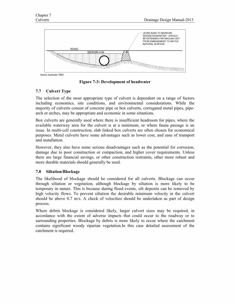
In flat terrain it may be necessary to construct levee banks (Figure 7.3) to achieve the
design headwater at the culvert location. Where necessary, approval of the local road
authorities should be obtained prior to construction of any levee banks.
Chapter 7
Culverts Drainage Design Manual-2013
Figure 7-3: Development of headwater
7.7 Culvert Type
The selection of the most appropriate type of culvert is dependent on a range of factors
including economics, site conditions, and environmental considerations. While the
majority of culverts consist of concrete pipe or box culverts, corrugated metal pipes, pipe-
arch or arches, may be appropriate and economic in some situations.
Box culverts are generally used where there is insufficient headroom for pipes, where the
available waterway area for the culvert is at a minimum, or where fauna passage is an
issue. In multi-cell construction, slab linked box culverts are often chosen for economical
purposes. Metal culverts have some advantages such as lower cost, and ease of transport
and installation.
However, they also have some serious disadvantages such as the potential for corrosion,
damage due to poor construction or compaction, and higher cover requirements. Unless
there are large financial savings, or other construction restraints, other more robust and
more durable materials should generally be used.
7.8 Siltation/Blockage
The likelihood of blockage should be considered for all culverts. Blockage can occur
through siltation or vegetation, although blockage by siltation is more likely to be
temporary in nature. This is because during flood events, silt deposits can be removed by
high velocity flows. To prevent siltation the desirable minimum velocity in the culvert
should be above 0.7 m/s. A check of velocities should be undertaken as part of design
process.
Where debris blockage is considered likely, larger culvert sizes may be required, in
accordance with the extent of adverse impacts that could occur to the roadway or to
surrounding properties. Blockage by debris is more likely to occur where the catchment
contains significant woody riparian vegetation.In this case detailed assessment of the
catchment is required.

Chapter 7
Drainage Design Manual – 2013 Culverts
Photo7-6: Culvert blocked by siltation and debris Tigray
7.9 Allowable Headwater
One or more of the following conditions will usually determine the allowable headwater
for a culvert:
• The elevation of upstream ponding should not cause unacceptable damage or
adverse effects to adjacent properties. The fact that floods may already enter
properties even without any road embankment should be ascertained in field
investigations or by design calculations;
• Where a road is designed not to be overtopped in the 1 in 50 year or 0.5% Annual
probability event for example, it is desirable to provide freeboard between the
design upstream floodwater surface and the upstream road shoulder edge. Where
this is not economically acceptable, pavement design should make allowance for
higher water levels, and the likely duration of inundation;
• In the event of both of the above conditions permitting a high headwater, the
associated outlet velocity may be intolerably high. In this case, the allowable
headwater may have to be reduced to limit the outlet velocity to an acceptable
value, that is, one that does not cause unacceptable scouring; and
• Where practicable, it is desirable to keep the headwater in the road reserve or
upstream with the landowner’s permission.
7.10 Tailwater
Tailwater (TW) is the depth at the culvert outlet, measured from the water surface in the
downstream channel to the invert of the culvert. Tailwater is significant for the following
reasons;
• A high tailwater may cause the culvert to flow full or under pressure, so increasing
the headwater necessary to pass the flow; and
• A low tailwater relative to the depth of flow in the culvert can result in erosion of
the downstream channel.
If the channel is regular in shape and steady uniform flow conditions can be expected, the
tailwater level can be determined using Manning’s formula as follows:
• Select a trial value of TW. This could be based on the suggested maximum velocity
in Table 7.1 and A = Q/V. The closer the trial TW is to the true value, the less
iteration will be required;
• Calculate the average channel velocity for this trial depth using Manning’s formula,
then calculate Q = AV;

Chapter 7
Culverts Drainage Design Manual-2013

Chapter 7
Drainage Design Manual – 2013 Culverts
• If the channel capacity exceeds the design discharge, recalculate with a reduced
depth; or if the channel capacity is less than the design discharge, recalculate with
an increased depth; and
• Repeat these steps until the estimated channel capacity is within 10% of the design
discharge.
For complex channels, backwater models such as HY8, the Hydraulic Engineering Centres
River Analysis System (HEC-RAS) MIKE, or ISIS can be used, although this would
normally only be necessary for large catchments.
7.11 Hydraulic Performance of Culverts
The most important consideration in culvert hydraulics is whether the flow is subject to
inlet or outlet control. Figure 7.4 shows the range of flow types commonly encountered in
culverts. For inlet control two distinct regimes exist, depending on whether the inlet is
submerged or not submerged. Outlet control occurs in long culverts, culverts laid on flat
grades and with high tailwater depths. In designing culverts, the type of control is
determined by adopting the greater of the headwater depths calculated for both inlet
control and outlet control.

Chapter 7
Culverts Drainage Design Manual-2013
Figure 7-4: Typical conditions under which standard culverts operate
7.12 Inlet Control
When the capacity of the culvert barrel is greater than that of the inlet, the culvert is subject
to inlet control. Then the important factors are the cross-sectional area of the culvert barrel,
the depth of headwater or ponding at the entrance and the entrance conditions, including
the entrance type, existence and angle of headwalls and wing walls, and the projection of
the culvert into the headwater pond.

Chapter 7
Drainage Design Manual – 2013 Culverts
For one-dimensional flow, the relationship between the discharge and the upstream energy
can be computed by an iterative process.
Inlet control can occur with the inlet submerged and the outlet not submerged. Under these
conditions, the flow contracts to a supercritical jet immediately downstream from the inlet.
When the tailwater depth exceeds critical depth, hc and the culvert is laid on a steep grade,
flow remains supercritical in the barrel and a hydraulic jump will form near the outlet. If
the culvert is laid on a slope less than critical, then a hydraulic jump will form in the barrel.
When the culvert flows under inlet control, the roughness and length of the culvert barrel
and the outlet conditions (including the depth of tailwater) are not factors in determining
culvert capacity. An increase in the slope of the culvert reduces headwater only to a small
degree, and can normally be neglected for conventional culverts flowing under inlet
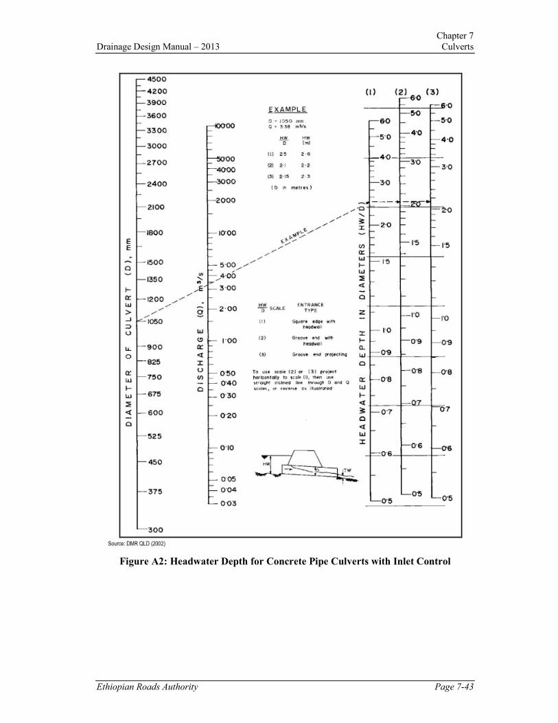
control. Design charts for the design of concrete culverts with inlet control are provided in
Appendix 7A.
7.13 Outlet Control
With outlet control the culvert flow is restricted to the discharge which can pass through
the conduit for a given level of water in the outlet channel (tailwater level). The slope,
cross-sectional area, roughness and length of the culvert barrel have to be considered as
these losses exceed the inlet losses. However, inlet edge geometry can still affect the
capacity.
In general the control will be at the outlet if the culvert slope is less than critical. A
tailwater depth equal to 80% or more of the height of the culvert barrel/cell will usually
indicate outlet control, except in rolling or mountainous country with the culvert on natural
surface slopes. However, a check of the design assuming inlet control is such an easy
process that it forms part of standard design procedure.
Culverts flowing with outlet control can flow with the culvert barrel full or with the barrel
part-full for all of the culvert length. With outlet control, and both the inlet and the outlet
submerged the culvert flows full and under pressure. The culvert, also, can flow full over
part of its length with part-full flow at the outlet. The point at which the water surface
breaks away from the barrel soffit depends on the tailwater depth and culvert grade, and
can be determined by using flow profile calculations.
If the culvert is laid at a flat grade, outlet control can occur with both inlet and outlet not
submerged, and part-full flow throughout the culvert length will be flowing under sub-
critical conditions. Variations of these main types can occur, depending on the relative
value of critical slope, normal depth, culvert height and tailwater depth. While the potential
flow conditions shown in Figure 7.4 are the most common for simple culverts, different
flow conditions are possible where complex culvert structures are required and advice may
be required from an expert in such cases.
Chapter 7
Culverts Drainage Design Manual-2013
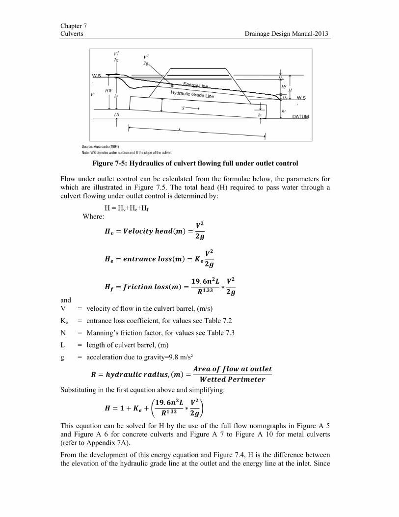
Figure 7-5: Hydraulics of culvert flowing full under outlet control
Flow under outlet control can be calculated from the formulae below, the parameters for
which are illustrated in Figure 7.5. The total head (H) required to pass water through a
culvert flowing under outlet control is determined by:
H = Hv+He+Hf
Where:
�� = ������ ������ = ����
�� = �������������� = ������
�� = ������������ = ��. ������. ∗ ����
and
V = velocity of flow in the culvert barrel, (m/s)
Ke = entrance loss coefficient, for values see Table 7.2
N = Manning’s friction factor, for values see Table 7.3
L = length of culvert barrel, (m)
g = acceleration due to gravity=9.8 m/s²
� = ����"�����"�, ��� = $��������%��"��&���'������
Substituting in the first equation above and simplifying:
� = � + �� + )��. ������. ∗ ����*
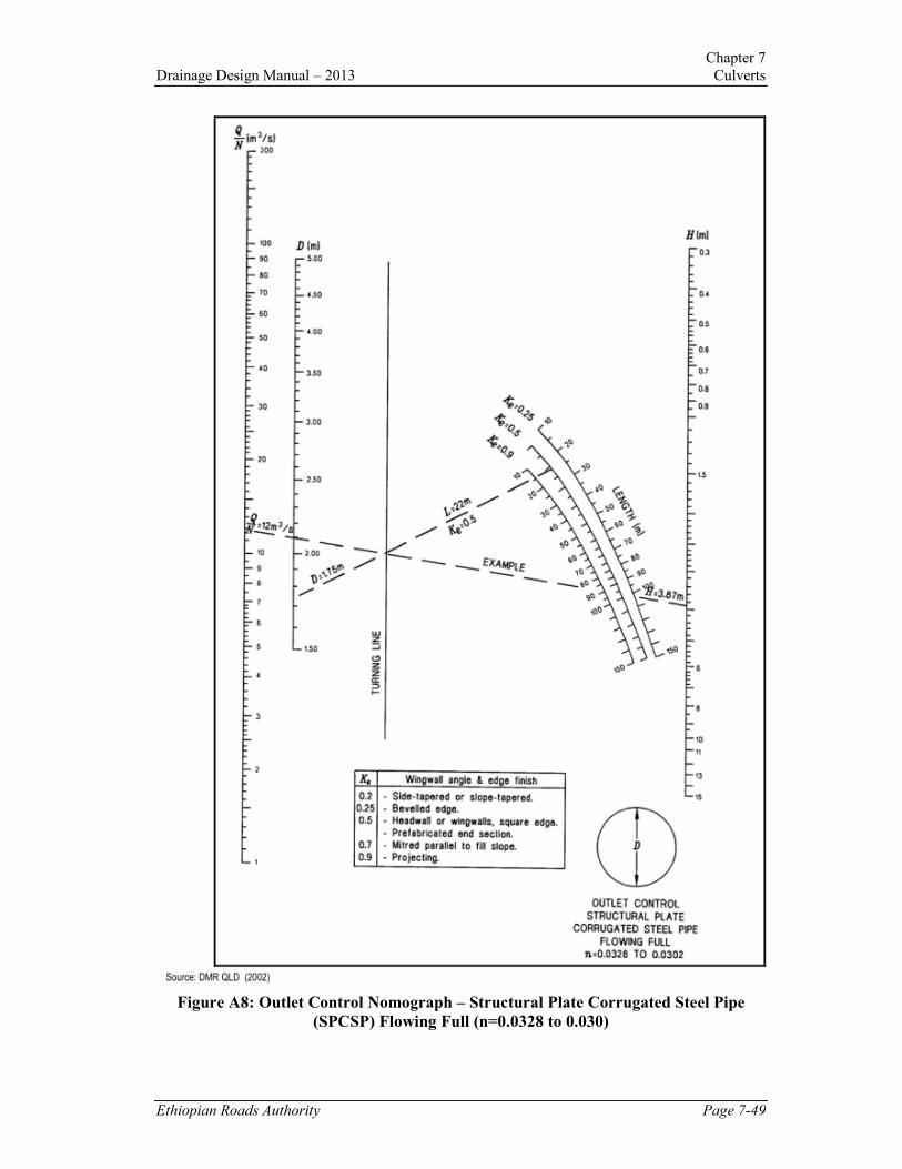
This equation can be solved for H by the use of the full flow nomographs in Figure A 5
and Figure A 6 for concrete culverts and Figure A 7 to Figure A 10 for metal culverts
(refer to Appendix 7A).
From the development of this energy equation and Figure 7.4, H is the difference between
the elevation of the hydraulic grade line at the outlet and the energy line at the inlet. Since
Chapter 7
Drainage Design Manual – 2013 Culverts
the velocity head in the entrance pool usually is small when ponded conditions occur
(v2/2g ≈ 0), the water surface of headwater pool elevation can be assumed to equal the
elevation of the energy line.
Notes: The effect of wingwalls reduces with multi-cell culverts for 3 – 6 cell culverts,
assume entrance loss for wingwalls 100 to 250 to barrel; for culverts with more than 6
cells, assume wingwalls parallel (extension of sides), regardless of actual wings.
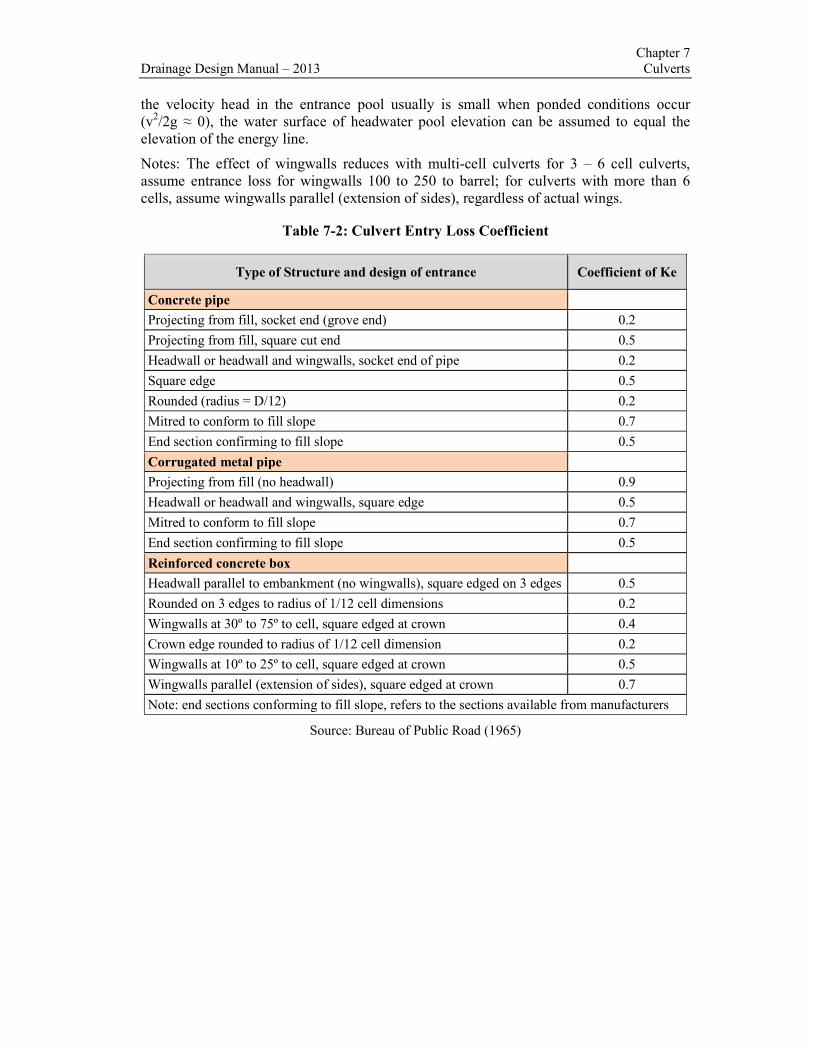
Table 7-2: Culvert Entry Loss Coefficient
Type of Structure and design of entrance Coefficient of Ke
Concrete pipe
Projecting from fill, socket end (grove end) 0.2
Projecting from fill, square cut end 0.5
Headwall or headwall and wingwalls, socket end of pipe 0.2
Square edge 0.5
Rounded (radius = D/12) 0.2
Mitred to conform to fill slope 0.7
End section confirming to fill slope 0.5
Corrugated metal pipe
Projecting from fill (no headwall) 0.9
Headwall or headwall and wingwalls, square edge 0.5
Mitred to conform to fill slope 0.7
End section confirming to fill slope 0.5
Reinforced concrete box
Headwall parallel to embankment (no wingwalls), square edged on 3 edges 0.5
Rounded on 3 edges to radius of 1/12 cell dimensions 0.2
Wingwalls at 30º to 75º to cell, square edged at crown 0.4
Crown edge rounded to radius of 1/12 cell dimension 0.2
Wingwalls at 10º to 25º to cell, square edged at crown 0.5
Wingwalls parallel (extension of sides), square edged at crown 0.7
Note: end sections conforming to fill slope, refers to the sections available from manufacturers
Source: Bureau of Public Road (1965)

Chapter 7
Culverts Drainage Design Manual-2013
Table7-3: Recommended Manning’s n Values for Pipe
Type of Conduit Wall Description Manning’s n
Concrete Pipe Smooth Walls 0.010-0.013
Concrete Boxes Smooth Walls 0.012-0.015
Corrugated Metal Pipes and Boxes, 68mm x 13mm corrugations 0.022-0.027
Annular or Helical Pipe 150mm x 25mm corrugations 0.022-0.025
125mm x 25mm corrugations 0.025-0.026
75mm x 25mm corrugations 0.027-0.028
150mm x 50mm structural plate 0.033-0.035
230mm x 64mm structural plate 0.033-0.037
Corrugated Metal Pipes, Helical 68mm x 13mm corrugations 0.012-0.024
Corrugations, Full Circular Flow
Spiral Rib Metal Smooth Walls 0.012-0.013
Headwater depth under outlet control is calculated according to the equation:
HW = H + ho - LSo
where:
ho=tailwater depth (m)
L=length of culvert, (m)
So= slope of culvert barrel, (m/m).
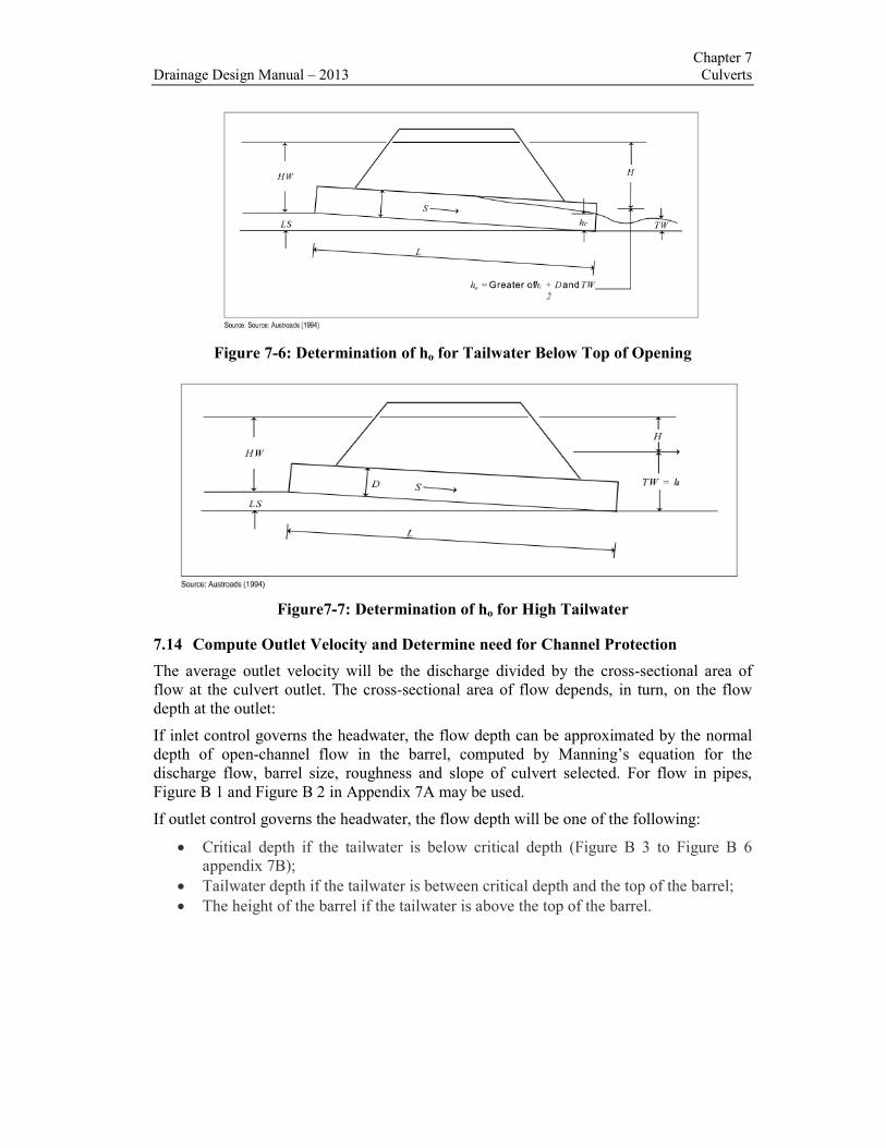
The various components of this equation are illustrated in Figure 7.5 and Figure 7.6
The tailwater level (ho) to be adopted when the tailwater elevation (TW) is below the soffit
of the culvert at the outlet is the greater of the two values:
+&�� � +,�
Where:
hc=Tailwater depth (m)
D=Diameter of culvert, (m).
For calculation of the outlet velocity, the TW may be slightly different than shown in Step
11 in Figure 7.6.
Chapter 7
Drainage Design Manual – 2013 Culverts
Figure 7-6: Determination of ho for Tailwater Below Top of Opening
Figure7-7: Determination of ho for High Tailwater
7.14 Compute Outlet Velocity and Determine need for Channel Protection
The average outlet velocity will be the discharge divided by the cross-sectional area of
flow at the culvert outlet. The cross-sectional area of flow depends, in turn, on the flow
depth at the outlet:
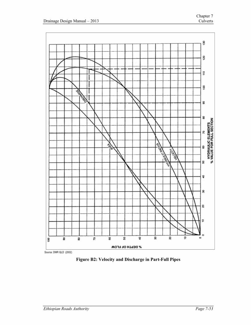
If inlet control governs the headwater, the flow depth can be approximated by the normal
depth of open-channel flow in the barrel, computed by Manning’s equation for the
discharge flow, barrel size, roughness and slope of culvert selected. For flow in pipes,
Figure B 1 and Figure B 2 in Appendix 7A may be used.
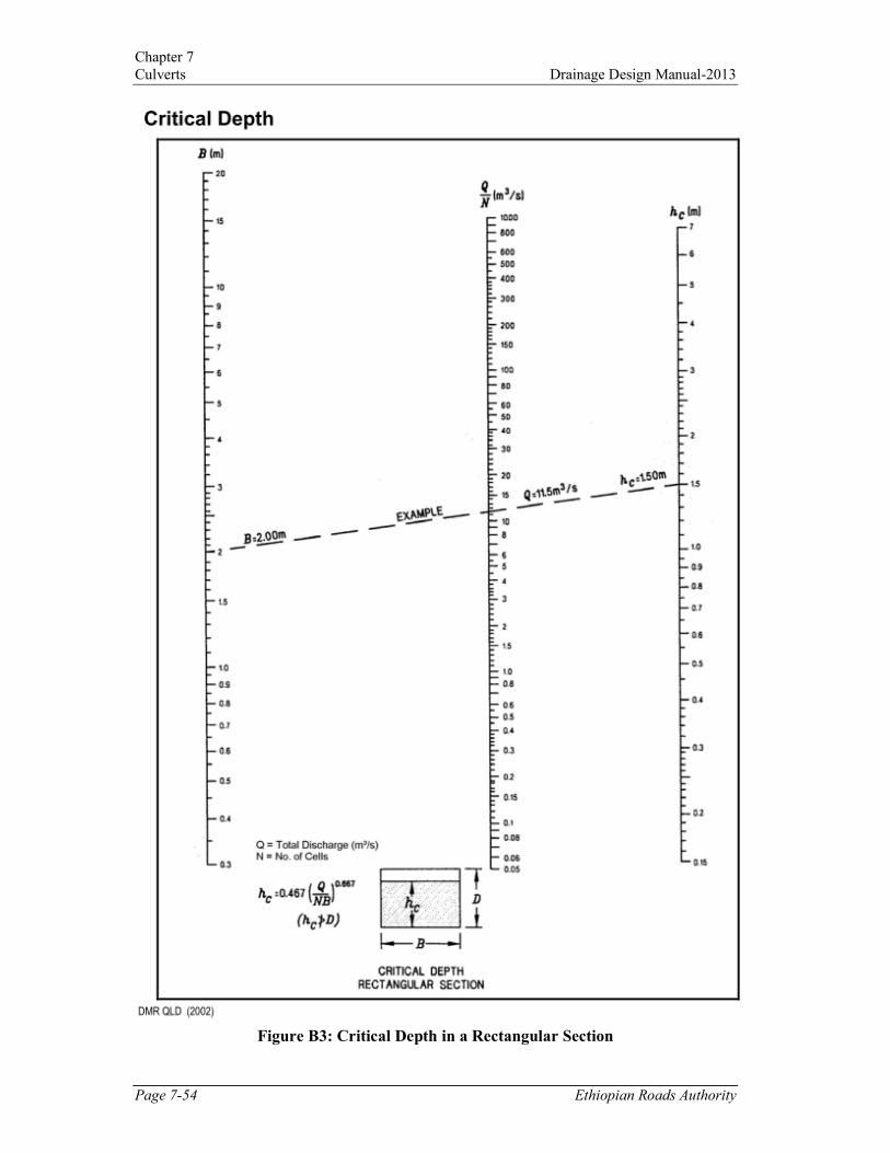
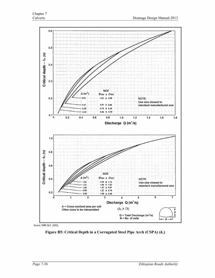
If outlet control governs the headwater, the flow depth will be one of the following:
• Critical depth if the tailwater is below critical depth (Figure B 3 to Figure B 6
appendix 7B);
• Tailwater depth if the tailwater is between critical depth and the top of the barrel;
• The height of the barrel if the tailwater is above the top of the barrel.

Chapter 7
Culverts Drainage Design Manual-2013
7.15 Culvert End Treatment
Culvert end treatments, including the shape of culvert ends, end structures such as
wingwalls, cut-offs and anchorages, and erosion control measures for the adjoining fill and
channel, may be required to perform one or more of the following functions:
• Prevent fill from encroaching on the culvert opening;
• Prevent erosion of the fill and adjacent channel;
• Prevent undermining of culvert ends;
• Inhibit seepage and piping through the bedding and backfill;
• Meet traffic safety requirements;
• Improve the appearance of large culverts;
• Resist hydraulic uplift forces on corrugated metal pipe culverts; and
• Strengthen the ends of large flexible culverts, especially those with mitred or
skewed ends.
7.16 Typical End Treatments
Headwalls and wingwalls are the most common end treatment. An apron is generally
incorporated between the wingwalls to limit scour of the streambed. They are usually
constructed from reinforced concrete, but can be formed from masonry, rock-filled gabions
or mattresses, or concrete-filled mattresses.
Mitred ends are generally limited to corrugated metal pipe culverts, where the end of the
pipe is cut parallel to the slope of the embankment. The area of embankment around the
ends of the culvert is usually paved with concrete or rock.
Projecting ends are used where the ends of the culvert project from the face of the
embankment. Although they are the least costly end treatment, they are not commonly
used because they do not meet safety requirements and are visually objectionable.
7.17 Scour Issues
7.17.1 Estimation of Scour Depths
Flow from culverts will generally have a higher velocity than that of the natural
watercourse and this can result in erosion of the bed and banks of the channels. When the
depth and/or extent of the scour hole is such that it undermines the foundations of
thestructure or its outlet wing walls, structural damage can occur leading to collapse.
The potential for scour should be assessed for all culverts. The maximum scour depth
should be determined for the natural bed material and then compared with the depth of the
culvert foundation level to assess the risk of failure. The following design formulae are
suggested for estimating maximum scour depths, ys, and the extent of the scour hole, Ls,
for the two distinct cases of rectangular culverts or pipes producing two dimensional (2D)
jets and circular or square culverts producing three dimensional (3D) jets: It is
recommended that HEC-RAS or other similar software should be used to assess scour.
These formulae have been added here for the drainage engineer to have an understanding
of theoretical principles. For detailed information, the designer should refer to relevant text
books.

Chapter 7
Drainage Design Manual – 2013 Culverts
7.17.2 2D Jets Scour Depth
Use the equation due to Hoffmans (1997).
-. = /502 3 /1 −67683 -8
where ysis the depth of scour below the invert of the culvert (in m), y1is the vertical
thickness of the jet(in m), U1is the depth-averaged velocity in the jet, andU2 is the depth-
averaged velocity in the receiving channel (both in m/s). k is a non-dimensional scour
factor dependent on the d 90size of the sediment (for which 90% of the material by weight
is fines) in the channel bed (in mm) and is defined as:
2 = 2.95;<=8/[email protected] < ;<= < 12.5CC
2 = 6.85@AB;<= > 12.5CC
Scour Extent
The overall length of the scour hole can be estimated to be 5 to 7 times the scour depth.
7.17.3 3D Jets Scour Depth
Use the equation due to Ruff et al (1982)
-. = 2.07I ) JKLIM*
=.NM
where y sis the depth of scour below the invert of the outfall or culvert (in m), Q is the
flow rate (in m3/s), g is the acceleration due to gravity (m/s
2) and D is the diameter of the
pipe (in m) where y sis the depth of scour below the invert of the outfall or culvert (in m),
Q is the flow rate (in m3/s), g is the acceleration due to gravity (m/s
2) and D is the diameter
of the pipe (in m).
Scour Extent
The overall length of the scour hole will be approximately 7 times the scour depth.The
above formulae apply to horizontal jets.
7.17.4 Design of Scour Protection
Scour protection measures reduce the vulnerability of a structure to failure by lining the
bed material with a more erosion-resistant surface. Together with optimisation of the
outfall layout, this is one of the most common means of avoiding or controlling scour
problems. One of the most common materials used is riprap, or loose quarry stone that is
placed in a controlled way to provide a blanket for scour protection.
There is a wide range of proprietary and non-proprietary scour protection materials and the
choice depends on a range of factors: construction cost/ availability, environmental
considerations, accessibility and construction restraints, underwater or dry construction,
maintenance issues, etc. It should be noted that scour protection may need to be extended
beyond the immediate vicinity of the predicted scour hole since residualturbulence can
affect the stability of the bed and banks of the receiving channel (Refs 16 and 17).

Chapter 7
Culverts Drainage Design Manual-2013
Riprap
Simple guidelines for sizing riprap downstream of culverts (or outfalls) are given by Bohan
(1970) (Ref 21):
;I = 0.25OP @AB-Q < I
2
;I = 0.25OP − 0.15@AB-Q ≥ I
2
where d can be taken as the d50size of the stone, D is the pipe diameter, yTis tailwater depth
and Fcis the Froude number of the flow discharging from the outfall or culvert:
OP = 68KLI
where U1is the mean flow velocity at the culvert outlet and g is the acceleration due to
gravity. The length of the scour protection blanket, Lp is dependent on the value of Fc:
@ABOS ≤ 1
UVI = 8
@ABOP > 1
UVI = 8 + 17WAL8=OP @AB-Q < I2
UVI = 8 + 55WAL8=OP @AB-Q ≥ I2
In order to secure the scour protection blanket in place, this should be turned downwards
into the bed at its downstream end for a distance of at least one pipe diameter In some
cases it may be more economical to include an energy dissipation measure downstream of
the pipe or culvert to reduce the energy of the flow (see, for example, Peterka, 1978, for
design guidance and layout details - Ref 19).
Photo 7-7: Outlet Protection with Riprap

Chapter 7
Drainage Design Manual – 2013 Culverts
7.18 Managing Sediment
Sediment deposits within culverts, especially multi-cell culverts, can cause significant
operational and maintenance problems.
Occasionally sediment traps (basins) are constructed upstream of culverts. In these cases,
an access ramp for maintenance must be provided to allow de-silting of the trap.
In critical areas, or for long culverts where maintenance is extremely difficult, a small
sediment trap/weir can be constructed at the inlet to divert low flows to just one or two
culvert cells. This will allow the flow to enter the remaining cells only during high flows.
These sediment weirs should be designed to be fully drowned during major flood events so
that no adverse backwater effects occur.
It is important that sediment traps are designed so that maintenance activities are able to be
undertaken in a practical and economic manner. Factors that should be considered include
access to the basin for the removal of sediment and debris, access for low loaders
delivering plant, and the type of plant that will be necessary (e.g. the reach of a backhoe
compared to an excavator).
7.19 Debris Control
The performance of culverts can be compromised by the accumulation of debris at inlets.
This accumulation can cause failure of the drainage structure, possibly resulting in over-
topping of the roadway by floodwaters, with ensuing damage to the embankment or to the
properties upstream and downstream of the culvert. Where there is likelihood of a culvert
being so affected, consideration should be given to the installation of a debris control
structure.
7.20 Improved Inlets
The capacity of a culvert operating under inlet control can be significantly increased by
providing a more efficient inlet, which reduces the flow concentration at the entrance and
increases the flow depth in the barrel. For culverts operating under outlet control, the
entrance losses are not a significant component of the total energy losses and major inlet
improvements usually are not justified.
Major types of improvements, include bevelled inlets, depressed inlets and tapered inlets.
The aim of these major improvements is to increase the velocity head or the effective
headwater depth.
The incorporation of a sudden drop in the inlet as a grade control structure is referred to as
a ‘drop inlet’. Drop inlets can result in high approach velocities upstream of the drop.
These velocities can cause safety problems and bed scour. To avoid such problems, a small
weir structure can be placed at the crest of the drop, or else concrete lining may be
appropriate. To avoid upstream ponding, a free-draining, low-flow, V-notch can be formed
in the weir. Drop inlets are not recommended in regions where fish migration is required.

Chapter 7
Culverts Drainage Design Manual-2013
Photo7-8:Drop Inlet Structure
7.21 Safety
7.21.1 Trafic Safety
An exposed culvert end (projecting from the plane of the batters) acts as an unyielding
obstruction, likely to bring an out of control vehicle to an abrupt stop, causing considerable
damage to the vehicle and high deceleration forces on the occupants.
Where a road safety barrier is not provided, culvert ends should be designed so that they
will not present an obstruction to vehicles running off the road. This can be achieved by
covering exposed sides with fill, providing headwalls or wingwalls which will not present
an obstruction, or mitring culvert ends flush with the embankment surface.
The location of culvert ends placed flush with the embankment slope should be indicated
by markers to reduce hazards to equipment operators and others. High culverts in
populated areas should be fenced whenever possible.
The hazard presented by culverts under private and side-road entrances should be
minimised by placing them as far as practicable from the roadway, and avoiding the use of
headwalls.
7.21.2 Child Safety
Culverts can also be an attraction for adventurous and inquisitive children. At locations
where long culverts could be a hazard, especially in urban areas, fencing, swing gates or
grates at upstream ends should be considered to prevent entry. However, this may cause
blockages and reduce the efficiency of the culvert.
7.22 Design Limitations
Allowable Headwater:is the depth of water that can be ponded at the upstream end of the
culvert that will be limited by one or more of the following:
• Will not damage up stream property;
• Not higher than 300 mm below the edge of the shoulder;
• Equal to an HW/D not greater than 1.5;
• No higher than the low point in the road grade; and
• Equal to the elevation where flow can be diverted around the culvert.

Chapter 7
Drainage Design Manual – 2013 Culverts
Review (Check) Headwater: the review headwater is the flood depth that:
• Does not exceed 500 mm increase over the existing 100-year flood in the vicinity
of buildings or habitations; and
• Has a level of inundation that is tolerable to upstream property and roadways for
the review discharge.
Tailwater Relationship – Channel
• Evaluate the hydraulic conditions of the downstream channel to determine a
tailwater depth for a range of discharges which includes the review discharge (see
Chapter 6);
• Calculate backwater curves at sensitive locations or use a single cross section
analysis;
• Use the critical depth and equivalent hydraulic grade line if the culvert outlet is
operating with a free outfall; and
• Use the headwater elevation of any nearby, downstream culvert if it is greater than
the channel depth.
Tailwater Relationship – Confluence or Large Water Body
• Use the high water elevation that has the same frequency as the design flood if
events are known to occur concurrently (statistically dependent); and
• If statistically independent, evaluate the joint probability of flood magnitudes and
use a likely combination resulting in the greater tailwater depth.
Maximum Velocity:the maximum velocity at the culvert exit shall be consistent with the
velocity in the natural channel or shall be mitigated with:
• Channel stabilization (see Chapter 6); and
• Energy dissipation (see Chapter 9).
Minimum Velocity:the minimum velocity in the culvert barrel should result in a tractive
force (τ=γdS) greater than critical τ of the transported streambed material at low flow rates.
• Use 0.8 meters per second when streambed material size is not known;
• If clogging is probable, consider installation of a sediment trap or size culvert to
facilitate cleaning.
Storage (Temporary or Permanent):if storage is being assumed upstream of the culvert,
consideration shall be given to:
• The total area of flooding;
• Limiting the average time that bank-full stage is exceeded for the design flood, to
48 hours in rural areas, or 6 hours in urban areas; and
• Ensuring that the storage area will remain available for the life of the culvert
through the purchase of right-of-way or easement.
Flood Frequency:the flood frequency used to design or check the culvert shall be based
on:
• The values given in Table 2-1, Chapter 2;
• An economic assessment or analysis to justify the flood frequencies greater or
lesser than the minimum flood frequencies listed in Table 2-1 in Chapter 2.

Chapter 7
Culverts Drainage Design Manual-2013
7.23 Microcomputer Solution
Culvert hydraulic analysis can also be accomplished with the aid of the HY8 Culvert
Analysis Software, version 7.2. Further explanations and worked example about this
software are given in Chapter 15. There are several other types of software that can be used
to ease the design process, e.g. ISIS, Mike 11 etc.
7.24 Flood Routing Culvert Design
Flood routing through a culvert is a practice that evaluates the effect of temporary
upstream ponding caused by the backwater of the culvert. The findings from culvert
analyses will be conservative if flood routing is not considered. If allowable headwater is
selected without considering flood routing then costly over-design of both the culvert and
outlet protection may result depending on the amount of temporary storage involved. There
are many ramifications associated with culvert flood routing, including:
• Right-of-way of the upstream property may be required;
• There is a perceived loss of a subjective safety factor;
• There are credibility concerns, both in legal as well as in technical negotiations;
• Environmental concerns must be evaluated;
• Realistic assessments need to be made of potential flood hazards; and
• An estimate of sediment problems must be made.
Ignoring temporary storage effects by reducing the selected design flood magnitude and
assuming that this provides a factor of safety is not recommended. This practice results in
inferior safety factors at the culvert site, as the culvert is then dependent on the amount of
temporary storage available. Further, with little or no temporary storage at a site, the factor
of safety would be one, or, essentially, there would be no factor of safety. If a factor of
safety is desired, it is essential that flood routing practices be used to insure consistent and
defensible factors of safety are used at all culvert sites. In steep terrain, there is little
storage and this effect can be neglected but in flat terrain storage upstream of a culvert can
dramatically reduce the peak design discharge and should be considered in culvert design.
Improved hydrology methods or changed catchment area conditions are factors that can
cause an older, existing culvert to be inadequate. A culvert analysis that relies on findings
that ignore any available temporary storage may be misleading. A flood routing analysis
may show that what was thought to be an inadequate existing culvert is, in fact, adequate.
Often existing culverts require replacement due to corrosion or abrasion. This can be very
costly, particularly where a high fill is involved. A less costly alternative is to place a
smaller culvert inside the existing culvert. A flood routing analysis may demonstrate,
where there is sufficient storage, that this is acceptable and that no increase in flood hazard
results.
With legal proceedings or in resolving conflicting design findings it is essential that
creditable and defensible practices be used. By ignoring flood routing where significant
storage occurs, findings may be discredited. With legal proceedings, claims of design
negligence may result depending on the nature of the case.
With culvert flood routing, a more realistic assessment can be made where environmental
concerns are important. The temporary time of upstream ponding can be easily identified.
This allows environmental specialists to assess whether such ponding is beneficial or
harmful to local environmental features such as fisheries, wetlands, and uplands.

Chapter 7
Drainage Design Manual – 2013 Culverts
Potential flood hazards increase whenever a culvert increases the natural flood stage. Some
of these hazards can conservatively be assessed without flood routing. However, some
damages associated with culvert backwater are time dependent and thus require an estimate
of depth versus duration of inundation. Some vegetation and commercial crops can tolerate
longer periods and greater depths of inundation than others can. Such considerations
become even more important when litigation is involved.
Complex culvert sediment deposition (“silting”) problems require the application of a
sediment routing practice. This practice requires a time-flood discharge relationship, or
hydrograph. This flood hydrograph must be coupled with a flood discharge-sediment
discharge relationship in order to route the sediment through the culvert site.
There are situations where culvert sizes and velocities obtained through flood routing will
not differ significantly from those obtained by designing to the selected peak discharge and
ignoring any temporary upstream storage. This occurs when:
• There is no significant temporary pond storage available (as in deep incised
channels);
• The culvert must pass the design discharge with no increase in the natural channel’s
flood stage; and
• Runoff hydrographs last for long periods such as with irrigation flows.
7.24.1 Routing Equations
In addition to the previous Design Equations (Section 7.5), the following routing equations
shall be used.
The basic flood routing equation is:
X − Y = Z∆ �� (7-14)
�Z�∆\Y�]X�]X� = �Z�
∆]Y� (7-15)
For a finite interval of time, ∆t, equation 7.14 can be expressed by:
∆Z − ^∆ − ^_∆ (7-16)
From these equations:
X�]X�� = ∆Z
∆ + Y�� + Y�
� (7-17)
Where:
∆S=S2 – S1
S1 = storage volume in the temporary pond at the beginning of the incremental time
period, ∆t, m3
S2 = storage volume in the temporary pond at the end of the incremental time period, ∆t,
m3

Chapter 7
Culverts Drainage Design Manual-2013
∆t = incremental routing time interval selected to subdivide hydrograph into finite time
elements, s
I = average hydrograph inflow to the temporary pond during incremental time period,
∆t
I1 = instantaneous inflow to the temporary pond at the beginning of the incremental
time period ∆t, m3/s
I2 = instantaneous inflow at the end of the time period ∆t, m3/s
O = average outflow from the temporary pond during incremental time period ∆t, m3/s
O1 = instantaneous outflow at the beginning of the time period ∆t, m3/s
O2 = instantaneous outflow at the end of the time period ∆t, m3/s
7.25 References
1. J.M Norman, R.J. Houghtalen, W.J. Johnston, "Hydraulic Design of Highway
Culverts," HDS No. 5, FUWA-IP-85-15, FUWA, Washington, D.C. 20590,1985
2. G.K. Young, J.S. Krolak, HYDRAIN - Integrated Drainage Design Computer
System, Volumes 1-6, FUWA-RD-88-120, FUWA, 1987.
3. A. Ginsberg, HY8 - Culvert Analysis Microcomputer Program, Applications Guide,
FHWA-EPD-87-101, and software available from McTrans Center, 512 Weil Hall,
University of Florida, Gainesville, Florida 32611.
4. "Guidelines for the Hydraulic Design of Culverts," Task Force on Hydrology and
Hydraulics, Subcommittee on Design, American Association of State Highway and
Transportation Officials, 341 National Press Bldg., Washington, D.C. 20045, 1975.
5. G.L. Bodhaine, Measurement of Peak Discharge at Culverts by Indirect Methods,
Techniques of Water-Resources Investigations of the USGS, Chapter A3, 1982.
6. G. Reihsen and L.J. Harrison, "Debris Control Structures," BEC No. 9, Hydraulics
Branch, Bridge Division, Office of Engineering, FHWA, Washington, D.C. 20590,
August 1971.
7. S.W. Jens, "Design of Urban Highway Drainage - The State of the Art," FHWA-TS-
79-225, Hydraulics Branch, Bridge Division, Office of Engineering, FHWA,
Washington, D.C. 20590, August 1979
8. "Design of Small Canal Structures," Bureau of Reclamation, Denver, Co., 1974.
9. 'Culvert Design System," FHWA-TS-80-245, Hydraulics Section, Wyoming
Highway Department, Cheyenne, Wyoming 82002, December 1980.
10. "Design Charts For Open Channel Flow," HDS No. 3, Hydraulics Branch, Bridge
Division, Office of Engineering, FHWA, Washington, D.C. 20590, 1973.
11. J.N. Bradley, "Hydraulics of Bridge Waterways," HDS No. 1, Second Edition,
Hydraulics Branch, Bridge Division, Office of Engineering, FHWA, Washington,
D.C. 20590, September 1973.
12. J.O. Shearman, W.H. Kirby, V.R. Schneider, and H.N. Flippo, "Bridge Waterways
Analysis Model, "FHWA-RD-86-108, FHWA, Washington, D.C.
13. H.W. King and E.F. Brater, "Handbook of Hydraulics, 'I Sixth Edition, McGraw-Hill
Book Co., 1976.

Chapter 7
Drainage Design Manual – 2013 Culverts
14. FHWA Hydraulic Design Series No. 5 (HDS5), Hydraulic Design of Highway
Culverts.
15. AASHTO Highway Drainage Guidelines, 1992.
16. ESCARAMEIA M. (1998). River and channel revetments. Thomas Telford
Publications, London,ISBN 0 7277 2691 9.
17. Construction Industry Research and Information Association (2002). Manual on
scour at bridges and other hydraulic structures. Report C551, London.
18. HOFFMANS GJCM (1997). Jet scour in the equilibrium phase. Journal of Hydraulic
Engineering, ASCE 124, No. 4, pp 430-437.
19. PETERKA AJ (1978). Hydraulic design of stilling basins and energy dissipators.
Engineering Monograph No. 25, US Bureau of Reclamation, Engineering Research
Center (Denver), USA.
20. RUFF JF, ABT SR, MENDOZA C, SHAIK A and KLOBERDANZ R (1982). Scour
at culvert outlets in mixed bed materials. Report FHWA/RD-82/011. Colorado State
University (Fort Collins), USA.
21. BOHAN J.P. (1970). Erosion and riprap requirements at culverts and storm drain
outlets. US Army Engineer Waterways Experiment Station. Research Report H-70-2

Chapter 7 Culverts
APPENDIX 7A - CONSTRUCTION DETAILS
Figure 7A -1: Type A Walls Concrete or Masonry
Drainage Design Manual
CONSTRUCTION DETAILS
1: Type A Walls Concrete or Masonry
Drainage Design Manual-2013
Drainage Design Manual – 2013
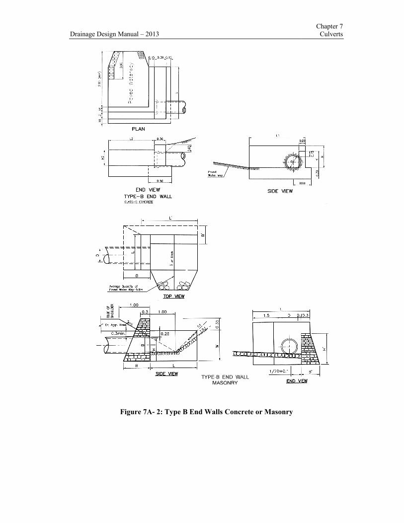
Figure 7A- 2: Type B End Walls Concrete or Masonry
2013
2: Type B End Walls Concrete or Masonry
Chapter 7 Culverts

Chapter 7 Culverts
Figure 7A-3: Type A Inlet Concrete or Masonry
Drainage Design Manual
3: Type A Inlet Concrete or Masonry
Drainage Design Manual-2013

Drainage Design Manual – 2013
Figure 7A
2013
Figure 7A-4: Curb Drop Inlet
Chapter 7 Culverts

Chapter 7
Culverts Drainage Design Manual-2013
APPENDIX 7B - WORKED EXAMPLE AND NOMOGRAPH
HY8-Culvert Analysis Example
Part I - Impute Data
Site Data - Culvert Crossing
Site Data Option: Culvert Invert Data
Inlet Station: 0.00 m
Inlet Elevation: 1420.00 m
Outlet Station: 10.00 m
Outlet Elevation: 1419.83 m
Number of Barrels: 2
Tail water Channel Data - Crossing
Tail water Channel Option:Trapezoidal Channel
Bottom Width: 4.00 m
Side Slope (H:V):1.00
Channel Slope: 0.0170
Channel Manning's n: 0.0250
Channel Invert Elevation: 1420.00 m
Roadway Data for Crossing:
Roadway Profile Shape: Constant Roadway Elevation
Crest Length: 12.00 m
Crest Elevation: 1424.00 m
Roadway Surface: Paved
Roadway Top Width: 8.00 m
Culvert Data Summary - Culvert crossing Barrel Shape: Concrete Box
Barrel Span: 2000.00 mm
Barrel Rise: 2000.00 mm
Barrel Material: Concrete
Embedment: 0.00 mm
Barrel Manning's n: 0.0120
Inlet Type: Conventional
Inlet Edge Condition: Square Edge (30-75º flare) Wingwall
Inlet Depression: NONE

Chapter 7
Drainage Design Manual – 2013 Culverts
Ethiopian Roads Authority Page 7-33

Chapter 7
Culverts Drainage Design Manual-2013
Page 7-34 Ethiopian Roads Authority
Part II – Out put
Table: 7B-1 - Culvert Summary Table: Culvert Crossing
Figure 7B-1 Water Surface Profile Plot for Culvert: Culvert Crossing
* Theoretical depth is impractical.Depth reported is corrected.
Inlet Elevation (invert): 1420.00 m, Outlet Elevation (invert): 1419.83 m, Culvert Length: 10.00
m,Culvert Slope: 0.0170.
Total
Discharge
(cms)
Culvert
Discharge
(cms)
Head-
water
Elevation
(m)
Inlet
Control
Depth
(m)
Outlet
Con-
trol
Depth
(m)
Flow
Type
Nor-
mal
Depth
(m)
Critical
Depth
(m)
Outlet
Depth
(m)
Tail
water
Depth
(m)
Outlet
Velo-
city
(m/s)
Tail water
Velocity
(m/s)
0.00 0.00 1420.00 0.000 0.000 0-NF 0.000 0.000 0.000 0.000 0.000 0.000
3.00 3.00 1420.58 0.583 0.0* 1-S2n 0.215 0.386 0.262 0.314 2.862 2.216
6.00 6.00 1420.93 0.926 0.0* 1-S2n 0.337 0.613 0.444 0.475 3.382 2.822
9.00 9.00 1421.22 1.222 0.0* 1-S2n 0.448 0.804 0.602 0.605 3.736 3.232
12.00 12.00 1421.49 1.485 0.0* 1-S2n 0.547 0.974 0.747 0.717 4.014 3.548
15.00 15.00 1421.73 1.730 0.0* 1-S2n 0.642 1.130 0.883 0.818 4.247 3.808
18.00 18.00 1421.97 1.970 0.0* 1-S2n 0.732 1.276 1.012 0.910 4.446 4.031
21.00 21.00 1422.22 2.219 0.0* 5-S2n 0.820 1.414 1.135 0.995 4.626 4.226
24.00 24.00 1422.49 2.486 0.0* 5-S2n 0.904 1.546 1.253 1.075 4.789 4.400
25.37 25.37 1422.62 2.616 0.0* 5-S2n 0.942 1.604 1.305 1.110 4.860 4.474
30.00 30.00 1423.10 3.101 0.0* 5-S2n 1.069 1.793 1.478 1.222 5.074 4.701
Chapter 7
Drainage Design Manual – 2013 Culverts
Ethiopian Roads Authority Page 7-35
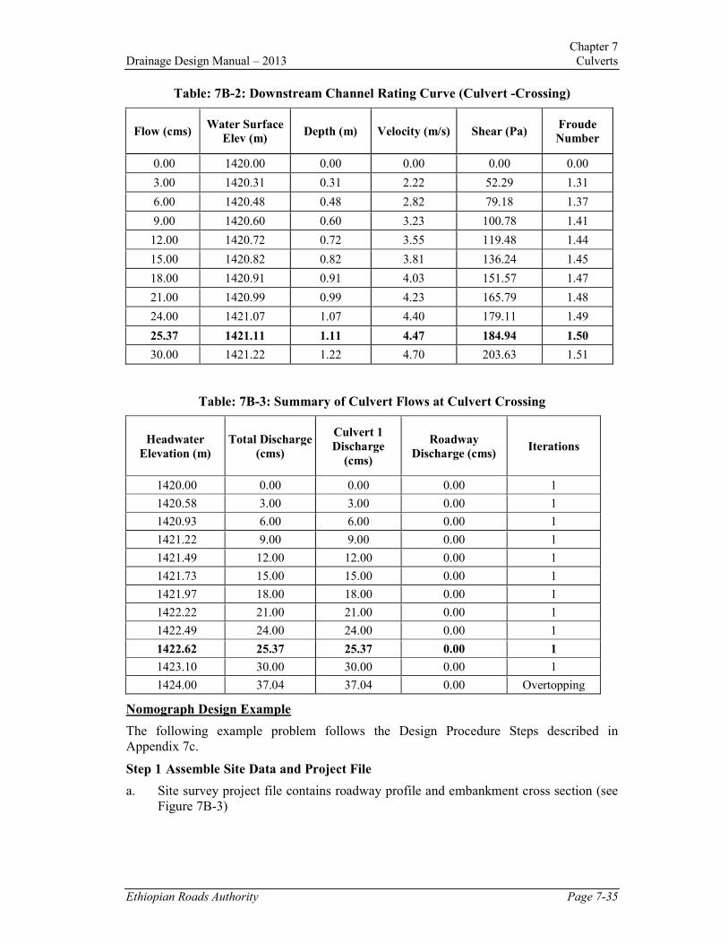
Table: 7B-2: Downstream Channel Rating Curve (Culvert -Crossing)
Flow (cms) Water Surface
Elev (m) Depth (m) Velocity (m/s) Shear (Pa)
Froude
Number
0.00 1420.00 0.00 0.00 0.00 0.00
3.00 1420.31 0.31 2.22 52.29 1.31
6.00 1420.48 0.48 2.82 79.18 1.37
9.00 1420.60 0.60 3.23 100.78 1.41
12.00 1420.72 0.72 3.55 119.48 1.44
15.00 1420.82 0.82 3.81 136.24 1.45
18.00 1420.91 0.91 4.03 151.57 1.47
21.00 1420.99 0.99 4.23 165.79 1.48
24.00 1421.07 1.07 4.40 179.11 1.49
25.37 1421.11 1.11 4.47 184.94 1.50
30.00 1421.22 1.22 4.70 203.63 1.51
Table: 7B-3: Summary of Culvert Flows at Culvert Crossing
Headwater
Elevation (m)
Total Discharge
(cms)
Culvert 1
Discharge
(cms)
Roadway
Discharge (cms) Iterations
1420.00 0.00 0.00 0.00 1
1420.58 3.00 3.00 0.00 1
1420.93 6.00 6.00 0.00 1
1421.22 9.00 9.00 0.00 1
1421.49 12.00 12.00 0.00 1
1421.73 15.00 15.00 0.00 1
1421.97 18.00 18.00 0.00 1
1422.22 21.00 21.00 0.00 1
1422.49 24.00 24.00 0.00 1
1422.62 25.37 25.37 0.00 1
1423.10 30.00 30.00 0.00 1
1424.00 37.04 37.04 0.00 Overtopping
Nomograph Design Example
The following example problem follows the Design Procedure Steps described in
Appendix 7c.
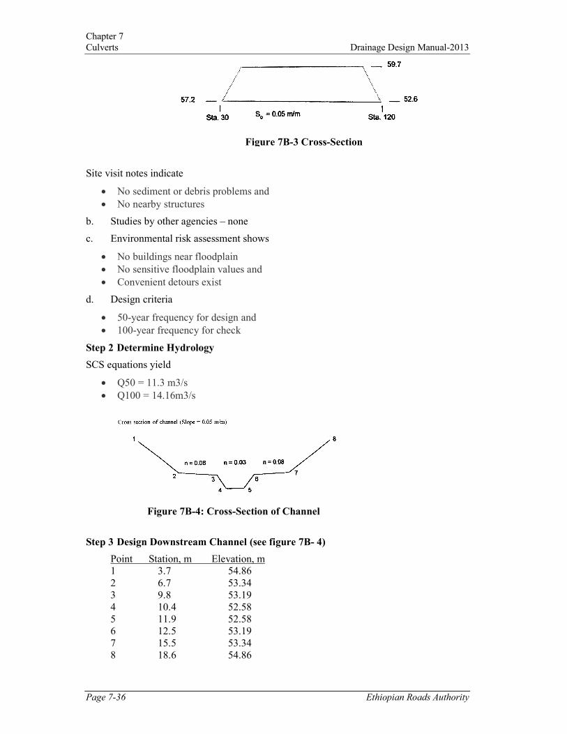
Step 1 Assemble Site Data and Project File
a. Site survey project file contains roadway profile and embankment cross section (see
Figure 7B-3)
Chapter 7
Culverts Drainage Design Manual-2013
Page 7-36 Ethiopian Roads Authority
Site visit notes indicate
• No sediment or debris problems and
• No nearby structures
b. Studies by other agencies – none
c. Environmental risk assessment shows
• No buildings near floodplain
• No sensitive floodplain values and
• Convenient detours exist
d. Design criteria
• 50-year frequency for design and
• 100-year frequency for check
Step 2 Determine Hydrology
SCS equations yield
• Q50 = 11.3 m3/s
• Q100 = 14.16m3/s
Step 3 Design Downstream Channel (see figure 7B- 4)
Point Station, m Elevation, m
1 3.7 54.86
2 6.7 53.34
3 9.8 53.19
4 10.4 52.58
5 11.9 52.58
6 12.5 53.19
7 15.5 53.34
8 18.6 54.86
Figure 7B-4: Cross-Section of Channel
Figure 7B-3 Cross-Section

Chapter 7
Drainage Design Manual – 2013 Culverts
Ethiopian Roads Authority Page 7-37
The rating curve for the channel calculated by normal depth yields:
Q (m3/s) TW (m) V (m/s)
2.83 0.43 3.39
5.66 0.63 4.18
8.50 0.76 4.87
11.33 0.85 5.34
14.16 0.93 5.73
Step 4 Summarize Data on Design Form (see Figure 7B-5)
Step 5 Select Design Alternative
Shape – box size-2135 mm by 1830 mm
Material – concrete
Entrance - Wingwalls, 45o bevel, rounded
Step 6 Select Design Discharge
(Qd = Q50 = 11.33 m3/s)
Figure 7B-5

Chapter 7
Culverts Drainage Design Manual-2013
Page 7-38 Ethiopian Roads Authority
Step 7 Determine Inlet Control Headwater Depth (HWi)
Use inlet control nomograph - Chart 7-6
a. D = 1.83 m
b. Q/B = 11.33/2.13 = 5.32
c. HW/D = 1.27 for 45o bevel
d. HWi = (HW/D)D = (1.27)1.83 = 2.32 m (Neglect the approach velocity)
Step 8 Determine Outlet Control Headwater Depth at Inlet (HWoi)
a. TW = 0.85 m for Q50 = 11.33 m3/s
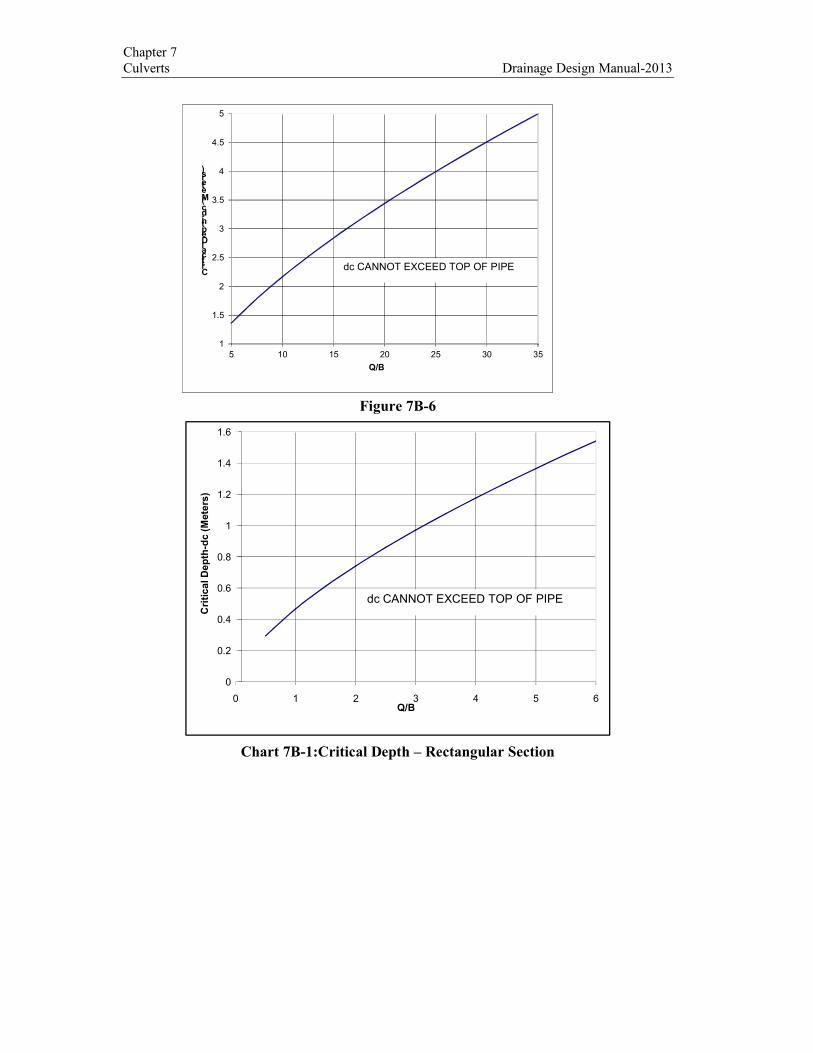
b. dc = 1.43 m from Chart 7-7
c. (dc + D)/2 = (1.43 + 1.83)/2 = 1.63 m
d. ho = the larger of TW or (dc + D/2)
ho = (dc + D)/2 = 1.63 m
e. KE = 0.2 from Table 7-2
f. Determine (H) - use Chart 7-8
• KE scale = 0.2
• culvert length (L) = 90 m
• n = 0.012 same as on chart
• area = 3.90 m2
• H = 0.85 m
g. HWoi = H + ho - SoL = 0.85 + 1.63 - (0.05)90 = - 2.02 m
HWoi is less than 1.2D, but control is inlet control, outlet control computations are
for comparison only
Step 9 Determine Controlling Headwater (HWc)
• HWc = HWi = 2.32 m > HWoi = - 2.02 m
• The culvert is in inlet control
Step 10 Compute Discharge over the Roadway (Qr)
a. Calculate depth above the roadway:
HWr = HWc - HWov = 2.32 – 2.59 = - 0.27m
b. If HWr≤ 0, Qr = 0
Step 11 Compute Total Discharge (Qt)
Qt = Qd + Qr = 11.33 m3/s + 0 = 11.33 m
3/s
Chapter 7
Drainage Design Manual – 2013 Culverts
Ethiopian Roads Authority Page 7-39
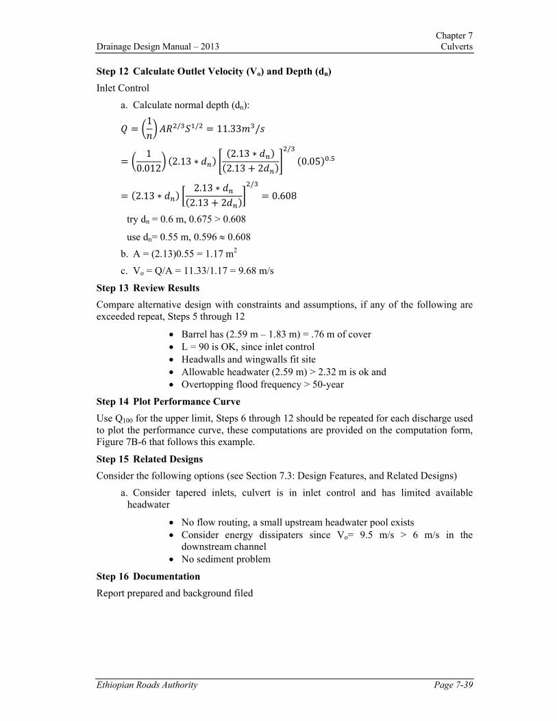
Step 12 Calculate Outlet Velocity (Vo) and Depth (dn)
Inlet Control
a. Calculate normal depth (dn):
J = /1`3ab7/?c8/7 = 11.33C?/e
= / 10.0123 �2.13 ∗ ;f� g
�2.13 ∗ ;f��2.13 + 2;f�h7/?
�0.05�=.M
= �2.13 ∗ ;f� i 2.13 ∗ ;f�2.13 + 2;f�j7/? = 0.608
try dn = 0.6 m, 0.675 > 0.608
use dn= 0.55 m, 0.596 ≈ 0.608
b. A = (2.13)0.55 = 1.17 m2
c. Vo = Q/A = 11.33/1.17 = 9.68 m/s
Step 13 Review Results
Compare alternative design with constraints and assumptions, if any of the following are
exceeded repeat, Steps 5 through 12
• Barrel has (2.59 m – 1.83 m) = .76 m of cover
• L = 90 is OK, since inlet control
• Headwalls and wingwalls fit site
• Allowable headwater (2.59 m) > 2.32 m is ok and
• Overtopping flood frequency > 50-year
Step 14 Plot Performance Curve
Use Q100 for the upper limit, Steps 6 through 12 should be repeated for each discharge used
to plot the performance curve, these computations are provided on the computation form,
Figure 7B-6 that follows this example.
Step 15 Related Designs
Consider the following options (see Section 7.3: Design Features, and Related Designs)
a. Consider tapered inlets, culvert is in inlet control and has limited available
headwater
• No flow routing, a small upstream headwater pool exists
• Consider energy dissipaters since Vo= 9.5 m/s > 6 m/s in the
downstream channel
• No sediment problem
Step 16 Documentation
Report prepared and background filed
Chapter 7
Culverts Drainage Design Manual-2013
Figure 7B-6
Chart 7B-1:Critical Depth – Rectangular Section
0
0.2
0.4
0.6
0.8
1
1.2
1.4
1.6
0 1 2 3 4 5 6
Critical Depth-dc (Meters)
Q/B
dc CANNOT EXCEED TOP OF PIPE
1
1.5
2
2.5
3
3.5
4
4.5
5
5 10 15 20 25 30 35
Critical Depth-dc (Meters)
Q/B
dc CANNOT EXCEED TOP OF PIPE

Chapter 7
Drainage Design Manual – 2013 Culverts
Ethiopian Roads Authority Page 7-41
APPENDIX 7C – DESIGN PROCEDURES AND NOMOGRAMS
Figure 7C-1. Culvert design flow chart in steps 1 – 13
Source: DMR QLD (2002)
Select design data:
• Maximum HW level for design Q;
• Natural flood level as TW level;
• Slope (usually natural channel
slope);
• Vmax and V average
• Culvert type
Size culverts;
Preliminary area of culverts
Q/2.5 0r Q/Vo
Use area to select one or more culverts
to meet area required
1
2
3
Analyse culvert assuming inlet control
(record calculation on Figure 7.7). Use
figure A1 and A4 to determine HEW1
4
Is HW1> HWmax ?
If no go to step 6
If yes return to step to and select larger
area for culverts
5
Analyse culvert assuming outlet
control. Calculate TW level accurately
(see section 7.18)
6
Is TW above culvert at the outlet?
If yes use ho= TW
If no ho is the larger of TW and ½ (dc
+ D) where dc obtained from figures
B3 to B6
7
Determine H
Use Figures A7 to A10
8
A
HW2 = H + ho - LSo
Is HW1 (step4) HW2?
If yes go to step 12
If no go to step 10
9
Outlet control governs.
Check HW. IS HW2>
HWmax?
If yes select new culvert
size and return to step 6. If
no go to step 11
10
Calculate V using Q/Ao.
Where Ao is greater than B
x dc or B xTW depth if free
outlet or B x D if
submerged.
11
Inlet control governs .
Culvert size and TW OK.
calculate V using Figures
B1 and B2 and Table
C32.1 for Manning’s n
12
If V > Vo or can outlet
protection be provided? If
an alternative culvert
configuration is to be
evaluated return to step 2
Otherwise END
13
Q Flow through culverts (m3/s)
HW Water level over invert level at inlet (m)
TW Water level over invert level at outlet (m)
Vmax Maximum velocity in natural channel (m/s)
Vavge Average velocity in natural channel (m/s)
Vo Allowable outlet velocity (m/s)
ho Calculated head at the outlet of the culvert
over the invert (m)
B Width of culvert (m)
D Height depth of culvert (m)
dc Critical depth of flow in culvert (m)
L Length of culvert (m)
So Slope of culvert (m/m)
V Calculated culvert out let velocity (m/s)
H HW - TW

Chapter 7
Culverts Drainage Design Manual-2013
Page 7-42 Ethiopian Roads Authority
Figure A1: Headwater Depth for Box Culvert with Inlet Control
Chapter 7
Drainage Design Manual – 2013 Culverts
Ethiopian Roads Authority Page 7-43
Figure A2: Headwater Depth for Concrete Pipe Culverts with Inlet Control

Chapter 7
Culverts Drainage Design Manual-2013
Page 7-44 Ethiopian Roads Authority
Figure A3: Inlet Control Nomograph – CMP and SPCSP Culvert
Chapter 7
Drainage Design Manual – 2013 Culverts
Ethiopian Roads Authority Page 7-45
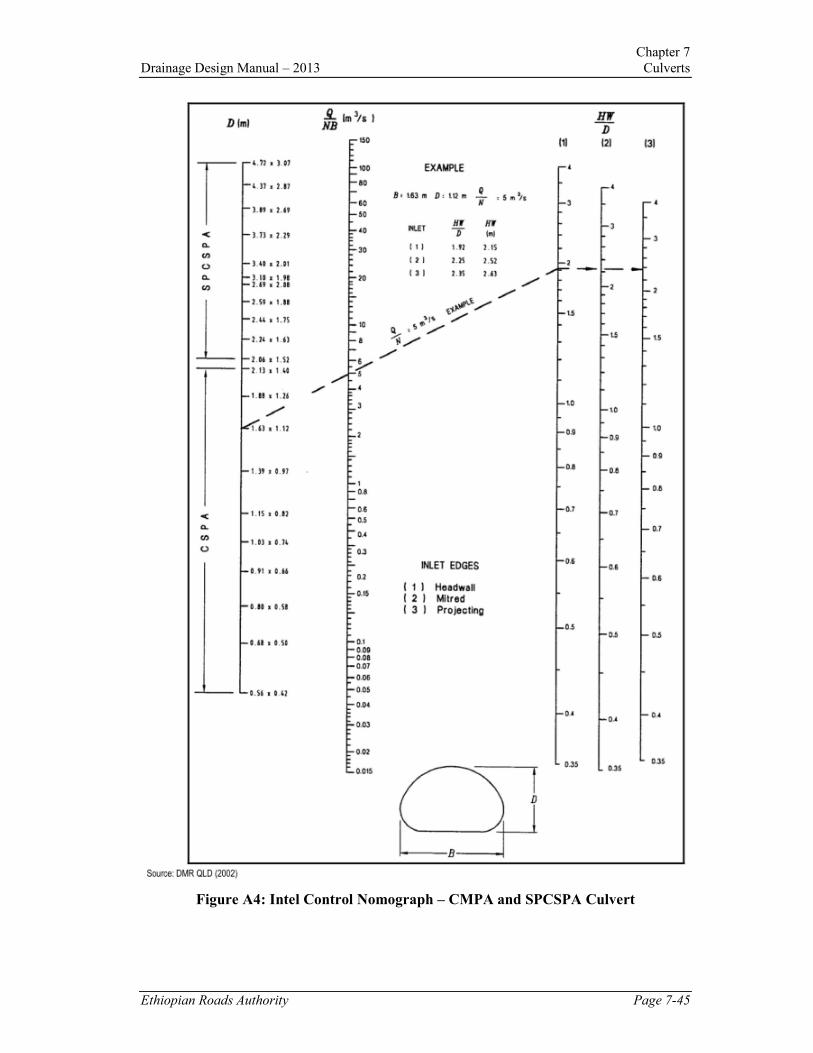
Figure A4: Intel Control Nomograph – CMPA and SPCSPA Culvert

Chapter 7
Culverts Drainage Design Manual-2013
Page 7-46 Ethiopian Roads Authority
Figure A5: Head for Concrete Box Culverts Flowing Full with Outlet Control
(n=0.012)

Chapter 7
Drainage Design Manual – 2013 Culverts
Ethiopian Roads Authority Page 7-47
Figure A6: Head for Concrete Pipes Flowing Full with Outlet Control (n=0.012)

Chapter 7
Culverts Drainage Design Manual-2013
Page 7-48 Ethiopian Roads Authority
Figure A7: Outlet Control Nomograph – Corrugated Metal Pipe (CMP) Flowing Full
(n=0.024)
Chapter 7
Drainage Design Manual – 2013 Culverts
Ethiopian Roads Authority Page 7-49
Figure A8: Outlet Control Nomograph – Structural Plate Corrugated Steel Pipe
(SPCSP) Flowing Full (n=0.0328 to 0.030)

Chapter 7
Culverts Drainage Design Manual-2013
Page 7-50 Ethiopian Roads Authority
Figure A9: Outlet Control Nomograph – Corrugated Steel Pipe Arch (CSPA)
Flowing Full (n=0.024)

Chapter 7
Drainage Design Manual – 2013 Culverts
Ethiopian Roads Authority Page 7-51
Figure A10: Outlet Control Nomograph -Structural Plate Corrugated Steel Pipe Arch
(SPCSPA) Flowing Full (N=0.0327 to 0.0906)

Chapter 7
Culverts Drainage Design Manual-2013
Page 7-52 Ethiopian Roads Authority
Figure B1: Discharge andVelocity in Round Pipes Flowing Full
Chapter 7
Drainage Design Manual – 2013 Culverts
Ethiopian Roads Authority Page 7-53
Figure B2: Velocity and Discharge in Part-Full Pipes
Chapter 7
Culverts Drainage Design Manual-2013
Page 7-54 Ethiopian Roads Authority
Figure B3: Critical Depth in a Rectangular Section

Chapter 7
Drainage Design Manual – 2013 Culverts
Ethiopian Roads Authority Page 7-55
Figure B4: Critical Depth in a Circular Pipe
Chapter 7
Culverts Drainage Design Manual-2013
Page 7-56 Ethiopian Roads Authority
Figure B5: Critical Depth in a Corrugated Steel Pipe Arch (CSPA) (hc)

Chapter 7
Drainage Design Manual – 2013 Culverts
Ethiopian Roads Authority Page 7-57
Figure B6: Critical Depth in aStructural Plate Corrugated Steel Pipe Arch (SPCSPA)
(hc)


Chapter 15
Drainage Design Manual – 2013 Computer Programs
Ethiopian Roads Authority Page 7-1
Related Documents