Chapter 15 – Drainage Design Memoranda TABLE OF CONTENTS CHAPTER 15 – DRAINAGE DESIGN MEMORANDA……………………………….……………15-I DDM01 Drainage Instructions…………………………………………….…………DDM01-1 DDM02 Drainage Descriptions………………………………………………………DDM02-1 DDM03 Minor Structure Excavation………………………………………………...DDM03-1 DDM04 Drainage Design at Railroads……………………………………………...DDM04-1 DDM05 Underdrains…………………………………………………………………..DDM05-1 DDM06 CTB Cost Participation Policy…………………………………….…..……DDM06-1

Welcome message from author
This document is posted to help you gain knowledge. Please leave a comment to let me know what you think about it! Share it to your friends and learn new things together.
Transcript

Chapter 15 – Drainage Design Memoranda
TABLE OF CONTENTS
CHAPTER 15 – DRAINAGE DESIGN MEMORANDA……………………………….……………15-I DDM01 Drainage Instructions…………………………………………….…………DDM01-1 DDM02 Drainage Descriptions………………………………………………………DDM02-1 DDM03 Minor Structure Excavation………………………………………………...DDM03-1 DDM04 Drainage Design at Railroads……………………………………………...DDM04-1 DDM05 Underdrains…………………………………………………………………..DDM05-1 DDM06 CTB Cost Participation Policy…………………………………….…..……DDM06-1

DDM1 – Drainage Instructions
VDOT Drainage Manual DDM 1-1 Chapter 15 – Drainage Design Memoranda
VIRGINIA DEPARTMENT OF TRANSPORTATION
LOCATION AND DESIGN DIVISION
DRAINAGE DESIGN MEMORANDUM
GENERAL SUBJECT: DRAINAGE INSTRUCTIONS
NUMBER: DDM 1.3
DATE: May 1, 2010
SPECIFIC SUBJECT:
CULVERTS, STORM SEWERS AND MISC. DRAINAGE ITEMS
SUPERSEDES:
DDM1.2, IIM-LD-121.15
ADMINISTRATOR APPROVAL: Stephen D. Kindy, P.E. State Hydraulics Engineer
EFFECTIVE DATE
This memorandum is effective upon receipt.
TYPE OF STRUCTURE SELECTION – Culverts
Because of the numerous types of drainage structures that are available, a general rule would dictate that various types such as box culverts, pipe culverts, standard bridges, etc., be taken into consideration when determining the type of proposed structure.
This design evaluation should consider cost comparisons, construction time,
earth movement, maintenance, and service life expectancy.
Design Considerations:
o All non-rigid* culverts:
- are comparatively flexible
- rely on uniform soil pressure around the entire circumference of the structure to maintain proper and equal load distributions
* Rev 4/10

DDM1 – Drainage Instructions
Chapter 15 – Drainage Design Memoranda
DDM 1-2 VDOT Drainage Manual
- are more sensitive to improper bedding and backfill than rigid structures
o Structural plate pipe arch culverts:
- concentrate considerable pressure in the haunch area. - require near perfect backfill and compaction in haunch area during
construction. - should be avoided wherever alternate structural shapes are
feasible, such as:
1.) aluminum or steel box culverts
2.) bottomless arch culverts on footings
3.) circular culverts buried below streambed
ACCEPTABLE MANNING ROUGHNESS COEFFICIENT (n)
The roughness coefficient for each pipe material represents the value for newly installed pipe and has been determined by laboratory tests with an adjustment factor to compensate for the additional losses experienced in actual field installations. Values may be higher for existing pipe installations that have experienced some deterioration.
MATERIAL ROUGHNESS COEFFICIENT (n) Concrete Pipe 0.013 PVC (Polyvinylchloride) Storm Drain Pipe (Smooth Interior) 0.011 Polyethylene Double Wall (Type S) *
(Smooth Interior) 0.012
Steel or Aluminum Spiral Rib Pipe 0.014 Polymer Coated Corrugated Steel Double Wall (Smooth Interior) 0.013 Corrugated Steel Pipe Fully Concrete Lined 0.013
* Rev 9/11 Deleted Information
DDM1 – Drainage Instructions
VDOT Drainage Manual DDM 1-3 Chapter 15 – Drainage Design Memoranda
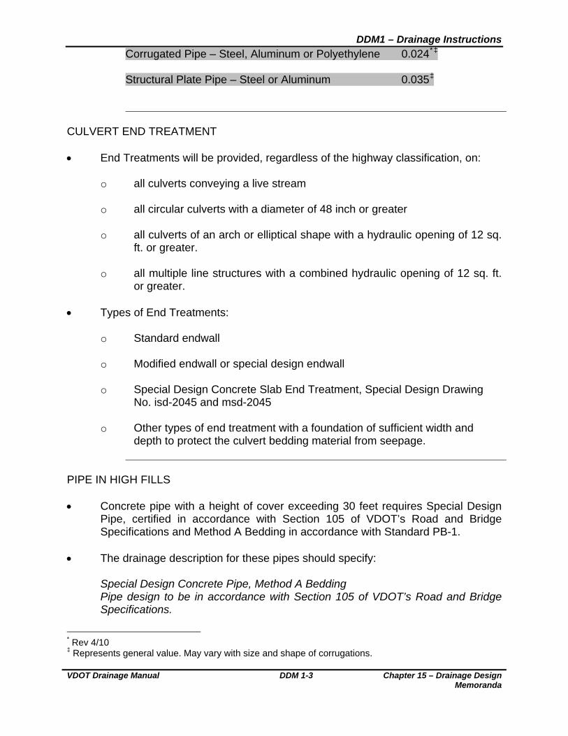
Corrugated Pipe – Steel, Aluminum or Polyethylene 0.024*‡ Structural Plate Pipe – Steel or Aluminum 0.035‡
CULVERT END TREATMENT End Treatments will be provided, regardless of the highway classification, on:
o all culverts conveying a live stream
o all circular culverts with a diameter of 48 inch or greater
o all culverts of an arch or elliptical shape with a hydraulic opening of 12 sq. ft. or greater.
o all multiple line structures with a combined hydraulic opening of 12 sq. ft.
or greater. Types of End Treatments:
o Standard endwall
o Modified endwall or special design endwall
o Special Design Concrete Slab End Treatment, Special Design Drawing No. isd-2045 and msd-2045
o Other types of end treatment with a foundation of sufficient width and
depth to protect the culvert bedding material from seepage.
PIPE IN HIGH FILLS Concrete pipe with a height of cover exceeding 30 feet requires Special Design
Pipe, certified in accordance with Section 105 of VDOT’s Road and Bridge Specifications and Method A Bedding in accordance with Standard PB-1.
The drainage description for these pipes should specify:
Special Design Concrete Pipe, Method A Bedding Pipe design to be in accordance with Section 105 of VDOT’s Road and Bridge Specifications.
* Rev 4/10 ‡ Represents general value. May vary with size and shape of corrugations.

DDM1 – Drainage Instructions
Chapter 15 – Drainage Design Memoranda
DDM 1-4 VDOT Drainage Manual
In order to facilitate inspection and future rehabilitation (if needed) of culverts in
fills (not cover) of 20 feet or greater, the minimum culvert size allowed/specified should be a 60 inch diameter. On Lower Functional Classification (LFC) roadways, as defined in the Allowable Pipe Type Tables in the Road and Bridge Standard PC-1, the District Construction or Maintenance Engineer and/or the Resident Manager/Engineer may waive the minimum 60 inch diameter size requirement provided that:*
o At locations where the hydraulic capacity would require a pipe diameter of
less than 60 inches, the minimum pipe diameter shall be that necessary for adequate hydraulic conveyance plus 12 inches with a 36 inch minimum diameter and a 60 inch maximum diameter. The table below shows the minimum pipe diameter to use based on that required for hydraulic capacity.
PIPE DIAMETER REQUIRED FOR USE IN HIGH FILLS
THEN USE THIS PIPE DIAMETER IN FILLS > 20’: IF THE MINIMUM PIPE DIAMETER REQUIRED TO MEET
HYDRAULIC CAPACITY IS: DESIRABLE MINIMUM
12” – 24” 36” 30” 42” 36” 48” 42”
60”
54” 48” - 60” 54” - 60”
o It is recognized that it will be potentially more difficult for the inspection,
maintenance and future rehabilitation (if necessary) of culverts in high fill areas if a size smaller than a 60 inch diameter is utilized.
SKEWED BOX CULVERT DETAILS
Where box culverts are to be constructed on a skew, the Drainage Designer is to request, from the Structure and Bridge Division, the required details for modification of the standard drawings. This information is to be requested on Form LD-423. Box Culvert skews should be shown to the nearest five (5) degree increment.
* Rev 4/10

DDM1 – Drainage Instructions
VDOT Drainage Manual DDM 1-5 Chapter 15 – Drainage Design Memoranda
EXISTING BOX CULVERT EXTENSIONS When the extension of an existing box culvert is required, the Drainage Designer
shall specify Standard BCE-01 as a part of the box culvert description on the plans.
SMALL BOX CULVERTS Box culverts with heights and widths less than 4 feet should be avoided due to
concerns with inspection and maintenance. If a box culvert with a height or width less than 4 feet is needed (e.g., for extension of an existing structure), the District Drainage Engineer should be consulted to determine if other alternate hydraulic structures are available.
PILE FOUNDATION DESIGN FOR BOX CULVERTS
When the Materials Division recommends pile foundations for box culverts, details are to be requested, by the Road Designer, from the Structure and Bridge Division on Form LD-422.
JACKING PIPE There are certain cases where it is not feasible to install pipe through the existing
embankment by the usual open trench method. The alternative is to jack the pipe through the embankment. The Drainage Designer is to specify the pipe as “Jacked Pipe” on the plans. The contractor then has the option of tunneling or boring the pipe in accordance with Section 302.03 of VDOT’s Road and Bridge Specifications. Foundation information shall be requested for any size pipe that is to be jacked or bored in order to determine the feasibility of this installation method.
Concrete pipe is normally employed in a jacking operation. In some cases, it is
preferred to jack a Smooth Wall Steel Pipe (See Sec. 232 of VDOT’S Road and Bridge Specifications) through the embankment as the encasement structure. A concrete (or occasionally metal or plastic*) pipe is then threaded inside of the steel pipe to act as the carrier for the stormwater. The void between the two pipes is to be pressure grouted in accordance with Section 302.03 of the VDOT Road and Bridge Specifications.
* Rev 4/10
DDM1 – Drainage Instructions
Chapter 15 – Drainage Design Memoranda
DDM 1-6 VDOT Drainage Manual
On some specific occasions, it has been deemed appropriate to install only the Smooth Wall Steel Pipe and to let it serve as the drainage pipe. THIS IS NOT TO BE CONSIDERED A UNIVERSALLY ACCEPTABLE PRACTICE.
The use of Smooth Wall Steel Pipe as the drainage pipe must conform to Notes 1, 2 and 4 for Table A of “Allowable Types of Pipe” as shown in St’d. PC-1. Any deviation from this policy must be approved by the State Location and Design Engineer and the District Materials Engineer.
FISH PASSAGE In areas of known fish habit, highway culverts are to be designed to
accommodate the passage of fish. The design criteria for such culverts can be found in the following publications.
o An Analysis of the Impediments to Spawning Migrations of Anadromous
Fish in Virginia Culverts (Pages 61 through 66) August 1985 by Mudre, Ney & Neves
o Nonanadromous Fish Passage in Highway Culverts
Report No. VTRC 96-R6 October 1995 by Fitch Summary of General Design Criteria:
o Criteria apply to normal water (ordinary high water) conditions.
o Set invert elevations of the low flow culvert 6 inches minimum below the
streambed.
o Maintain a depth, width and velocity of flow in the culvert that matches, as* nearly as practicable, the depth, width and velocity of flow in the natural channel up and down stream of the culvert.
PIPE REHABILITATION When existing pipe culverts are damaged or deteriorated such that they are no
longer functional or their functionality has been considerably impacted, a decision needs to be made as to what type of retrofit method should be employed. These methods include replacing the existing pipe or leaving it in place and lining it with one of several approved materials. The Drainage Designer should refer to the latest IIM LD-244 for guidance pertaining to the appropriate pipe rehabilitation methods to be used on each project.
* Rev 4/10
DDM1 – Drainage Instructions
VDOT Drainage Manual DDM 1-7 Chapter 15 – Drainage Design Memoranda
NON-STANDARD ROADSIDE DITCHES Safety, appearance, and economy necessitate that non-standard roadside ditches
not be used or their use be minimized to the greatest extent reasonable for all highway projects.
Where the volume, flow, or other considerations dictate enlarging or deepening the
roadside ditch or otherwise deviating from the standard designs, careful consideration must be given to the following:
o Using an enclosed drainage system, where economically feasible, in order
to eliminate the need for the non-standard roadside ditch or channel. o Minimizing the size and depth of the proposed non-standard roadside ditch
or channel.
o Flattening the front slope (the slope adjacent to the highway shoulder) of the non-standard roadside ditch or channel. Where right of way is available, or can reasonably be obtained, the front slope of the non-standard roadside ditch or channel should be no steeper than the front slope of the standard roadside ditch for the specific roadway classification involved.
o Locating necessary non-standard roadside ditches or channels as far from
the proposed highway shoulder as the existing or proposed right of way will reasonably allow.
BERM/TOE DITCH LOCATIONS Except where severe right-of-way limitations exist, a minimum of 5 feet is to be
provided between the end of the cut slope round-off and the front slope of a berm ditch. Additional right-of-way is to be obtained for construction and maintenance of the berm ditch.
Except where severe right of way limitations exist, a minimum of 5 feet is to be
provided between the toe of the fill slope and the front slope of a toe* ditch. Additional right of way is to be obtained for construction and maintenance of the ditch.
* Rev 4/10
DDM1 – Drainage Instructions
Chapter 15 – Drainage Design Memoranda
DDM 1-8 VDOT Drainage Manual
PIPE ON RADIUS Pipe may be laid on a radius when necessary to conform to design features,
alignment, or topography and to eliminate or minimize the need for manholes or other structures.
Pipe laid on a radius is to be concrete only.* Installation of concrete pipe on a radius may be done by one of the following
methods:
o Open Joint Method - relatively long radius - using standard pipe and open joints a maximum of 25% of the spigot length.
o Bevel Method - mid range radius - using modified pipe with one side
shorter than the other. o Bevel and Open Joint Method - for shortest radius - a combination of the
two methods above.
Bevel pipe is expensive to manufacture and somewhat difficult to install. It is generally more economical to use bend joints in cases where three or more joints of bevel pipe would be required.
The minimum radius obtainable is dependent upon two factors that differ
between manufacturers: o Spigot or tongue length o Pipe joint length The following table is a guideline for the minimum radius that should be obtainable using pipe from any manufacturer. A longer radius may be used as needed with the plan description denoting the method of obtaining the required radius. Certain manufactures may produce standard pipe joint lengths shorter than 8 feet. If so, a radius shorter than that shown in the table may be obtainable.
* Rev 4/10
DDM1 – Drainage Instructions
VDOT Drainage Manual DDM 1-9 Chapter 15 – Drainage Design Memoranda
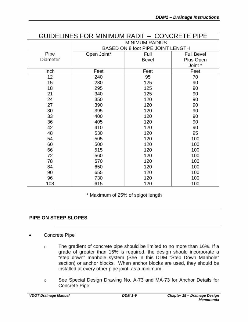
GUIDELINES FOR MINIMUM RADII – CONCRETE PIPE MINIMUM RADIUS
BASED ON 8 foot PIPE JOINT LENGTH
Pipe Diameter
Open Joint*
Full Bevel
Full Bevel Plus Open
Joint * Inch Feet Feet Feet 12 15 18 21 24 27 30 33 36 42 48 54 60 66 72 78 84 90 96
108
240 280 295 340 350 390 395 400 405 410 530 505 500 515 560 570 650 655 730 615
95 125 125 125 120 120 120 120 120 120 120 120 120 120 120 120 120 120 120 120
70 90 90 90 90 90 90 90 90 90 95
100 100 100 100 100 100 100 100 100
* Maximum of 25% of spigot length
PIPE ON STEEP SLOPES
Concrete Pipe
o The gradient of concrete pipe should be limited to no more than 16%. If a grade of greater than 16% is required, the design should incorporate a “step down” manhole system (See in this DDM “Step Down Manhole” section) or anchor blocks. When anchor blocks are used, they should be installed at every other pipe joint, as a minimum.
o See Special Design Drawing No. A-73 and MA-73 for Anchor Details for
Concrete Pipe.

DDM1 – Drainage Instructions
Chapter 15 – Drainage Design Memoranda
DDM 1-10 VDOT Drainage Manual
Corrugated pipe
o Corrugated pipe may be used on steep slopes in situations similar to those where shoulder slot inlets are proposed. Corrugated pipe should not be used in areas where the flow is expected to carry an abrasive bed load or that have PH and resistivity factors beyond the ranges specified in the Allowable Pipe Type Table C* in Standard PC-1 of the VDOT Road and Bridge Standards.
o See VDOT’s Road and Bridge Standard PI-1, for Anchor Details for
Corrugated Pipe. Step Down Manholes – In situations where the pipe grade needs to be more than
16%, structures at the upper end of the pipe system may be made deeper to help reduce the gradient. Additional “step down” manholes may also be added to the system to reduce the gradient. Where “step down” manholes are used, the Drainage Designer should provide any needed protection to prevent deterioration of the bottom of the manhole. This protection can be provided by the addition of a ½ inch steel plate in the bottom of the manhole. This protection should be considered for use if the vertical difference between the inverts of the inlet pipe and outlet pipe is 4 feet or greater and any one of the following factors are present or anticipated:
o The flow is expected to carry any abrasive material.
o Continuous live flow or live flow lasting several days may be expected.
o The size of the main pipes is 48” or greater in diameter (for circular pipe)
or the hydraulic opening is 12 sq. ft. or greater (for shapes other than circular).
Velocity dissipation is usually needed at the outlet of pipes on steep grades and
the Drainage Designer should provide the type of dissipation appropriate for velocity, pipe size, discharge and site constraints.
EXISTING DRAINAGE STRUCTURES
The Drainage Designer will determine if existing pipe and box culverts and
storm sewer pipe will remain and be utilized in the proposed design or removed or abandoned.
* Rev 4/10

DDM1 – Drainage Instructions
VDOT Drainage Manual DDM 1-11 Chapter 15 – Drainage Design Memoranda
Pipes to be removed, abandoned or cleaned out are to be indicated on the plans for bidding purposes and labeled "To be Removed", "To Be Abandoned", or "To Be Cleaned Out".
Any large amount of pipe and appurtenances to be removed, such as an existing
storm sewer system*, should be set up as a separate bid item and summarized in a separate column in the Incidental Summary.
When not set up as a separate pay item, small amounts of pipe and
appurtenances to be removed are included in the cost of Clearing and Grubbing (See Section 105.15 of the Road & Bridge Specifications) or may be included in the cost of Regular Excavation. (See latest IIM-LD-110 & General Note G-4)
Any drainage pipe that is abandoned and left in place shall be backfilled and
plugged in accordance with VDOT’s Road and Bridge Standard PP-1. These pipes are to be labeled on the plans ”To Be Abandoned”. The pay item for abandoning existing structures is “Flowable Backfill, Cu. Yds.” and includes furnishing and placing backfill material and plugging both ends of the drainage pipe.
The quantity for Flowable Backfill (includes flowable backfill or fine aggregate) is
to be estimated in accordance with Standard PP-1. This estimated quantity is to be summarized in the Drainage Summary. The pipe location/structure number should be shown in the Drainage Summary and the pipe size should be noted in the remarks column.
EXAMPLE:
D R A I N A G E S U M M A R Y
FLOWABLE BACKFILL
C.Y.
REMARKS
25 48 inch concrete pipe to be abandoned
General Note D-12 (See latest IIM LD-110) is to be included on the General Note
Sheet in all applicable project assemblies.
* Rev 4/10

DDM1 – Drainage Instructions
Chapter 15 – Drainage Design Memoranda
DDM 1-12 VDOT Drainage Manual
SOIL AND WATER DATA
The pH and resistivity of the soil and water as well as the velocity of flow, where*
an abrasive bed load is present or anticipated, are major factors in determining service life of metal pipe. An evaluation of the pH, resistivity and abrasive bed load potential must be conducted at each location where metal pipe is an allowable option and where any of the following conditions exist:
o Diameter or span of 36 inches or greater. For multiple pipe installations,
the span is measured between the interiors of the outside walls of the outer most pipes and is measured along a line perpendicular to the barrel of the pipe.
o Culvert is to be installed in a live stream environment (perennial or
intermittent).
o Culvert is to be installed in an area of documented premature pipe failure. The pH and resistivity analysis of the soil and water are to be requested from the
Materials Division for each culvert location meeting the noted criteria. In areas of documented premature pipe failure, the pH and resistivity analysis is to be requested for any type of proposed pipe material.
The locations where pH and resistivity information is needed should be noted on
the plans that are used to request culvert foundation information from the Materials Division.
It is recognized that the pH values of the soil and water could experience
seasonal changes during the course of the year. Should the Materials Division feel that the results of their initial pH test are not a true representation of the most severe conditions that the culvert will be exposed to, they should perform additional test and provide their best recommendation for the values to be used in determining the allowable pipe materials.
PROTECTIVE COATING FOR CULVERTS, STORM SEWERS AND CONCRETE STRUCTURES EXPOSED TO TIDAL WATER OR CORROSIVE ENVIRONMENT
Treatment of concrete exposed to the normal ebb and flow of tidal water is
defined in Section 404 of the VDOT Road and Bridge Specifications. Corrosive environment may be indicated in certain geographic areas by the degradation of concrete culverts, concrete lined ditches or other concrete
* Rev 4/10
DDM1 – Drainage Instructions
VDOT Drainage Manual DDM 1-13 Chapter 15 – Drainage Design Memoranda
structures. Proposed concrete items in these areas should have a protective coating or alternative materials should be considered.
The Drainage Designer is responsible for preliminary determination for need and
location of protective coating and is to specify in the drainage structure description where protective coating is required.
The final determination for need and location of protective coating should be
made by the Materials Division. The request for the final determination should be made either by the use of Form LD-252 or direct contact between the Drainage Designer and the Materials Division.
The Drainage Designer is responsible for ensuring that the following notation is
noted in the final drainage structure description on the plans and in the drainage summary:
Pipe or structure is to have protective coating applied in accordance with Section 404 of the VDOT Road and Bridge Specifications.
REQUESTING CULVERT DATA AND MATERIALS DIVISION RECOMMENDATIONS
The Drainage Designer will determine locations where foundation investigation
and other culvert data/recommendations are required. Foundation, pH, resistivity, abrasive bed load data and channel bed material
classification and recommendations for bedding, pipe camber and protective coating will be requested by the Roadway Designer, from the Materials Division, on Form LD-252. This request will be made immediately after locations requiring such information have been determined by the Drainage Designer or as soon after Field Inspection as possible.
FOUNDATION INVESTIGATION
Foundation data will be requested for all culvert installations with a diameter or
span of 36 inch or greater. For multiple pipe installations, the span is measured between the interiors of the outside walls of the outer most pipes and is measured along a line perpendicular to the barrel of the pipe. Foundation data may be requested for culvert installations with smaller spans if deemed necessary. Foundation data should be requested on all pipes of any size that are to be bored or jacked.
Foundation data should be requested for all SWM basins in order to determine if:

DDM1 – Drainage Instructions
Chapter 15 – Drainage Design Memoranda
DDM 1-14 VDOT Drainage Manual
o The native material will support the dam and provide adequate protection
for seepage under the dam. o Excavation from the basin may be used to construct the dam.
o Rock may be encountered in the area of excavation.
o A high water table is present which may alter the performance of the SWM
basin.
Borings shall be taken and information provided in accordance with Section 305.01(a) of the Materials Division Manual of Instructions. For large basins, more than one boring for the dam and one boring for the area of the basin may be needed. The number and locations of the borings are to be determined/requested by the Drainage Designer.
The existing foundation soils data is not to be shown on the plans, however, the
recommended amount of additional excavation and type of backfill material is to be shown in the drainage description.
At each location where a foundation investigation is requested for pipe or box
culvert installations, the Materials Division is to evaluate and classify the bed material in the outlet channel in close proximity of the downstream end of the proposed culvert. The bed material is to be classified in accordance with the AASHTO Soil Classification System. This information is needed in order to evaluate the scour potential at the culvert outlet. This information is to be requested by the Drainage Designer along with the other soil and water data for each appropriate culvert installation.
PIPE CAMBER
Construction of longitudinal camber in a pipeline shall be considered when all of
the following conditions are present:
o Grade of the pipe is less than 0.5% o Fills (not height of cover) greater than 20 feet o Diameter or span 36 inch or greater o Foundation is subject to settlement
The Drainage Designer will request that the Materials Division determine the
amount of anticipated settlement along the pipeline. This request will accompany

DDM1 – Drainage Instructions
VDOT Drainage Manual DDM 1-15 Chapter 15 – Drainage Design Memoranda
the request for culvert foundation data. The plan description for the structure will then note a camber equal to the amount of anticipated settlement.
STORMWATER MANAGEMENT BASIN OUTLET PIPE*
Culverts under or through the dam of a Stormwater Management Basin are to be
reinforced concrete pipe with rubber gaskets. Pipe - Road and Bridge Specification section: 232 (AASHTO M170), Gasket - Road and Bridge Specification section: 212 (ASTM C443).
A concrete cradle is to be used under the pipe to prevent seepage through the
dam. The concrete cradle is to extend the full length of the pipe. (See Road and Bridge Standard SWM-DR)
GENERAL NOTES
The Drainage Designer should refer to the latest IIM LD-110 for the general
notes pertaining to drainage, stormwater management and erosion and sediment control and shall select the appropriate notes to be used on each project.
POST INSTALLATION INSPECTION
A post installation visual/video camera inspection shall be conducted by the
Contractor on all pipes identified on the plans as storm sewer pipe and a select number of pipe culverts.
For pipe culverts, a minimum of one pipe installation for each size of material type
will be inspected or ten percent of the total amount for each size and material type summarized. All pipe installations on the plans not identified as storm sewer pipe shall be considered as culvert pipe for inspection purposes.
The drainage summary is to include a quantity for the total linear feet of Post
Installation Inspection (to include both pipe culverts and storm sewer pipe). * Rev 4/10

DDM1 – Drainage Instructions
Chapter 15 – Drainage Design Memoranda
DDM 1-16 VDOT Drainage Manual
DRAINAGE SUMMARIES
A Standard (Detailed) Summary is to be used on normal construction (C)
projects. A Streamlined Summary may be used on Minimum Plan (M), No Plan (N) and
Safety projects. When a specific type of pipe is required, such as concrete for the extension of an
existing pipe or corrugated for a shoulder slot inlet, etc., the type of pipe required is to be specified in both the Streamlined and Detailed Summary.
When the Drainage Summary sheets are compiled, the drainage items in the
Drainage Summary are to be referenced by their assigned structure numbers with no further reference to sheet number, station, or location needed.
At all locations allowing alternative materials, pipe should be specified as either*
“storm sewer pipe” or as “pipe” in the drainage descriptions and drainage summaries. Exceptions would be locations where an existing pipe is to be extended in kind, elliptical pipe is required, pipe is on a radius, corrugated pipe for DI-13 installations, or where a specific type of pipe is not allowed due to site specific conditions, i.e. pH, Resistivity, velocity, etc.
The total linear feet of all like size pipe shall be summarized by material or
category, i.e. storm sewer pipe or pipe. The following methods of listing pipe in the Standard Summary and the
Streamlined Summary are to be used to eliminate a possible contractor’s error when ordering the pipe.
* Rev 4/10
DDM1 – Drainage Instructions
VDOT Drainage Manual DDM 1-17 Chapter 15 – Drainage Design Memoranda
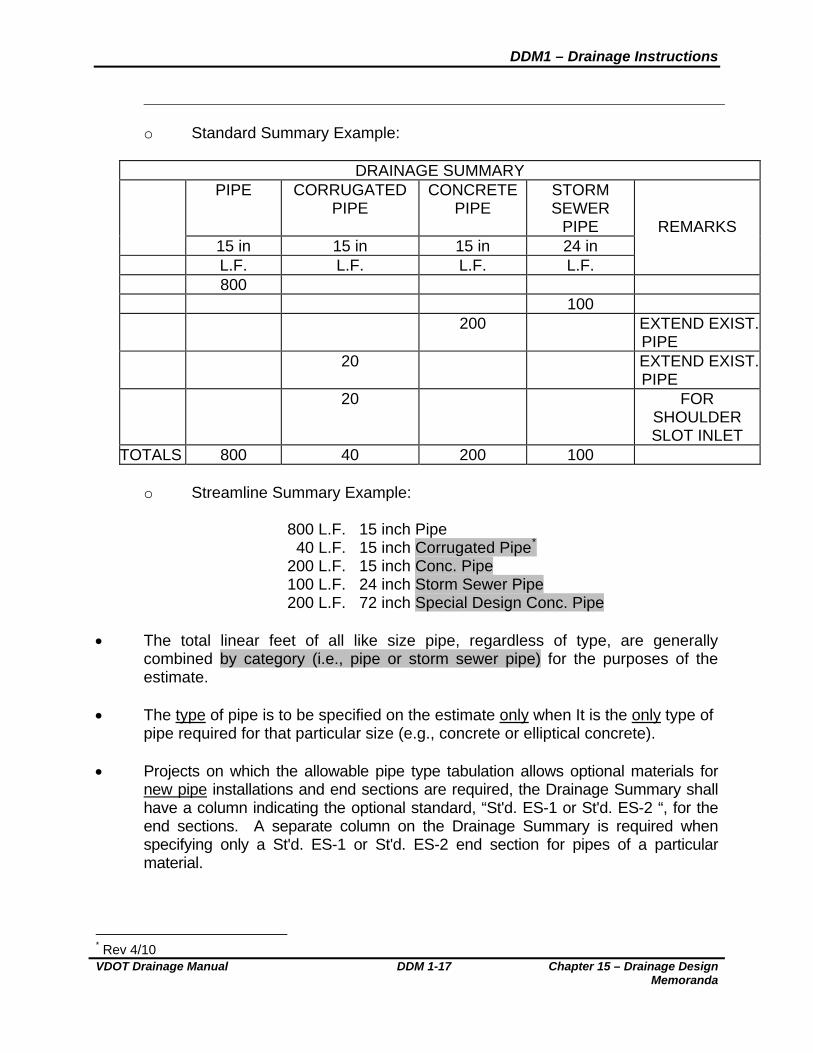
o Standard Summary Example:
DRAINAGE SUMMARY PIPE CORRUGATED
PIPE CONCRETE
PIPE STORM SEWER
PIPE
15 in 15 in 15 in 24 in L.F. L.F. L.F. L.F.
REMARKS
800 100 200 EXTEND EXIST.
PIPE 20 EXTEND EXIST.
PIPE 20 FOR
SHOULDER SLOT INLET
TOTALS 800 40 200 100
o Streamline Summary Example:
800 L.F. 15 inch Pipe 40 L.F. 15 inch Corrugated Pipe* 200 L.F. 15 inch Conc. Pipe 100 L.F. 24 inch Storm Sewer Pipe 200 L.F. 72 inch Special Design Conc. Pipe
The total linear feet of all like size pipe, regardless of type, are generally
combined by category (i.e., pipe or storm sewer pipe) for the purposes of the estimate.
The type of pipe is to be specified on the estimate only when It is the only type of
pipe required for that particular size (e.g., concrete or elliptical concrete). Projects on which the allowable pipe type tabulation allows optional materials for
new pipe installations and end sections are required, the Drainage Summary shall have a column indicating the optional standard, “St'd. ES-1 or St'd. ES-2 “, for the end sections. A separate column on the Drainage Summary is required when specifying only a St'd. ES-1 or St'd. ES-2 end section for pipes of a particular material.
* Rev 4/10
DDM1 – Drainage Instructions
Chapter 15 – Drainage Design Memoranda
DDM 1-18 VDOT Drainage Manual
ALLOWABLE PIPE TYPE TABLES*
The allowable pipe type criteria for culverts and storm sewers are presented in
Standard PC-1 in the Road and Bridge Standards. The allowable pipe types are those that provide for a 75 year service life for
pipes under the roadways and facilities that are constructed, funded or will ultimately be maintained by the Department.
A project specific Allowable Pipe Type Table for both culvert pipe and storm
sewer pipe (as appropriate) is to be shown at the end of the Drainage Summary for every project (C, M, and N).
The types of allowable pipe for each project will vary with classification of
roadway and geographic location within the State. Numerous combinations of pipe types may be used on a particular project.
It will be necessary to formulate a table(s) to specifically fit each project based
upon the various roadway classifications involved and location of the project. The Contractor has the option to install any of the allowable materials noted in
the project specific Allowable Pipe Type Tables unless otherwise noted on the plans.
Example tabulations for a Route 64 project in York County are as follows:
(The template for the following tables can be found in the CADD Cell Library)
* Rev 4/10

DDM1 – Drainage Instructions
VDOT Drainage Manual DDM 1-19 Chapter 15 – Drainage Design Memoranda
PIPE CULVERT EXAMPLE*
ALLOWABLE TYPE OF PIPE CULVERTS (UNLESS OTHERWISE SHOWN ON PLANS) (SEE ROAD AND BRIDGE STANDARD PC-I FOR HEIGHT OF COVER LIMITATIONS FOR EACH TYPE)
LOCATION C
ON
CR
ET
E
ALU
MIN
UM
CO
AT
ED
T
YP
E 2
CO
RR
UG
AT
ED
S
TE
EL
PO
LYM
ER
CO
AT
ED
(10
/10)
C
OR
RU
GA
TE
D S
TE
EL
UN
CO
AT
ED
GA
LVA
NIZ
ED
C
OR
RU
GA
TE
D S
TE
EL
GA
LVA
NIZ
ED
ST
EE
L S
TR
UC
TU
RA
L P
LAT
E
GA
LVA
NIZ
ED
ST
EE
L S
TR
UC
TU
RA
L P
LAT
E
WIT
H C
ON
CR
ET
E IN
VE
RT
CO
RR
UG
AT
ED
ALU
MIN
UM
A
LLO
Y
CO
RR
UG
AT
ED
ALU
MIN
UM
A
LLO
Y S
TR
UC
TU
RA
L P
LAT
E
PO
LYV
INY
LCH
LO
RID
E
(PV
C)
CO
RR
UG
AT
ED
R
IBB
ED
PIP
E (
SM
OO
TH
IN
TE
RIO
R)
PO
LYE
TH
YLE
NE
(P
E)
CO
RR
UG
AT
ED
TY
PE
C
PO
LYE
TH
YLE
NE
(P
E)
CO
RR
UG
AT
ED
TY
PE
S
Rte. 64 & Ramps X X X X X X X
Route 635 (Rural Local Road)
X X X X X X X X X X
Entrances X X X X X X X X X X
Shoulder Slot Inlet X X X X X X
STORM SEWER PIPE EXAMPLE
ALLOWABLE TYPE OF STORM SEWER PIPE (UNLESS OTHERWISE SHOWN ON PLANS)
(SEE ROAD AND BRIDGE STANDARD PC-I FOR HEIGHT OF COVER LIMITATIONS FOR EACH TYPE)
LOCATION
CO
NC
RE
TE
CO
RR
UG
AT
ED
ST
EE
L A
LUM
INU
M C
OA
TE
D T
YP
E 2
F
ULL
Y C
ON
CR
ET
E L
INE
D
ALU
MIN
UM
CO
AT
ED
TY
PE
2
SP
IRA
L R
IB P
IPE
PO
LYM
ER
CO
AT
ED
(10
/10)
C
OR
RU
GA
TE
D S
TE
EL
SP
IRA
L R
IB
PO
LYM
ER
CO
AT
ED
(10
/10)
C
OR
RU
GA
TE
D S
TE
EL
DO
UB
LE W
ALL
(S
MO
OT
H
INT
ER
IOR
)
ALU
MIN
UM
S
PIR
AL
RIB
PIP
E
PO
LYV
INY
LCH
LO
RID
E
(PV
C)
RIB
BE
D P
IPE
(S
MO
OT
H IN
TE
RIO
R)
PO
LYE
TH
YLE
NE
(P
E)
CO
RR
UG
AT
ED
TY
PE
S
Rte. 64 & Ramps X X X X
Route 635 (Rural Local Road) X X X X X X
STORM SEWER PIPE – SITE PLANS AND SUBDIVISIONS Plans and computations submitted to the Department for review must specify the
type of pipe used in the storm drain system and the storm drain system must be designed using the acceptable “n” value for that type. After plans are approved, no substitution or change in the type of pipe material will be allowed until the
* Rev 4/10
DDM1 – Drainage Instructions
Chapter 15 – Drainage Design Memoranda
DDM 1-20 VDOT Drainage Manual
designer or contractor submits revised plans to the Department for review. The* revised design cannot be implemented until approved by the Department.
STRUCTURES
DI-12 MULTIGRATE DROP INLETS The DI-12 Multigrate Drop Inlet is intended to provide one (1) standard grate
configuration to handle the various traversable and non-traversable ditch slopes. The DI-12 Drop Inlet is to be located only in areas not normally subject to traffic. The narrow width of the DI-12 grate makes it more adaptable to narrow medians where difficulty retaining a traversable slope has been experienced with the DI-7 Drop Inlet’s width. The DI-7 is still the preferred structure to be used in locations where a traversable slope can be maintained.
To provide the most economical design, all locations should first be checked to
see if the smaller chambered DI-12B or DI-12C drop inlet can be used. The size of the pipes entering and exiting the chamber will generally dictate whether or not a Standard DI-12B or DI-12C drop inlet can be used.
The Standard DI-12 and DI-12A drop inlets are to be specified at locations where
the DI-12B and DI-12C drop inlets cannot be used.
Toe of fill and top of cut ditches with 2:1 slopes may use the St’d. DI-12 series drop inlet as well as those in the St’d. DI-5 and St’d. DI-7 series.
DI-5 DROP INLETS
DI-5 Drop Inlets shall specify the type of cover (St’d. PG-2A Type) which most
closely matches the ditch configuration at the inlet location. This data shall be shown both in the structure description on the plans and in the Drainage Summary.
CONCRETE GUTTERS Where DI-7 or 12 series inlets are utilized to intercept concentrated flow (e.g.,
roadside, median, berm or toe ditches) the type of inlet that requires the concrete gutter should be specified (e.g., DI-7A, DI-7B, DI-12A or DI-12C).
* Rev 4/10
DDM1 – Drainage Instructions
VDOT Drainage Manual DDM 1-21 Chapter 15 – Drainage Design Memoranda
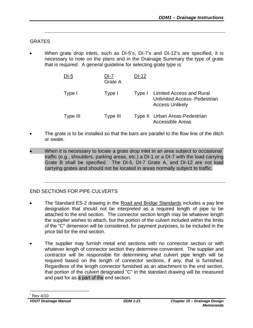
GRATES When grate drop inlets, such as DI-5’s, DI-7’s and DI-12’s are specified, it is
necessary to note on the plans and in the Drainage Summary the type of grate that is required. A general guideline for selecting grate type is:
DI-5 DI-7 DI-12 Grate A
Type I Type I Type I Limited Access and Rural Unlimited Access- Pedestrian Access Unlikely Type III Type III Type II Urban Areas-Pedestrian Accessible Areas
The grate is to be installed so that the bars are parallel to the flow line of the ditch or swale.
When it is necessary to locate a grate drop inlet in an area subject to occasional*
traffic (e.g., shoulders, parking areas, etc.) a DI-1 or a DI-7 with the load carrying Grate B shall be specified. The DI-5, DI-7 Grate A, and DI-12 are not load carrying grates and should not be located in areas normally subject to traffic.
END SECTIONS FOR PIPE CULVERTS The Standard ES-2 drawing in the Road and Bridge Standards includes a pay line
designation that should not be interpreted as a required length of pipe to be attached to the end section. The connector section length may be whatever length the supplier wishes to attach, but the portion of the culvert included within the limits of the "C" dimension will be considered, for payment purposes, to be included in the price bid for the end section.
The supplier may furnish metal end sections with no connector section or with
whatever length of connector section they determine convenient. The supplier and contractor will be responsible for determining what culvert pipe length will be required based on the length of connector sections, if any, that is furnished. Regardless of the length connector furnished as an attachment to the end section, that portion of the culvert designated "C" in the standard drawing will be measured and paid for as a part of the end section.
* Rev 4/10
DDM1 – Drainage Instructions
Chapter 15 – Drainage Design Memoranda
DDM 1-22 VDOT Drainage Manual
It is especially important that inspectors and other field personnel be aware of these instructions in order that an end section will not be rejected simply because the length of the connector is not the same as that shown on the Standard drawing. This variance is entirely acceptable provided the contractor has appropriately adjusted the length of the pipe.
PIPE ENDWALLS WITH LOAD CARRYING GRATE Pipe endwalls with load carrying grates (St'ds. EW-11 and EW-11A) are designed
as a safety feature to prevent an errant vehicle from encountering the hazards of a collision with conventional endwalls or end sections. They are intended for use on low height embankments which would be traversable by an out of control vehicle and where guardrail would otherwise not be required or desired.
Standard EW-11 is to be used for cross drain culverts. The grate configuration
must be installed perpendicular to the edge of the shoulder line. Standard EW-11A is designed for use at crossover locations where there is no
other alternative to placing a pipe culvert under the crossover. The Drainage Designer is to carefully study each situation before specifying
Standard EW-11 or EW-11A Endwalls on the plans. Guidelines for the use of these structures are as follows:
o Pipe endwalls with load carrying grates are to be used with traversable
slopes (3:1 or flatter) on all classes of highways. o Pipe endwalls with load carrying grates are not to be installed where
guardrail is required.
o Pipe endwalls with load carrying grates will not be required on culverts with ends located outside of the normal clear zone width. For clear zone width guidelines, see Section A-2 of the VDOT Road Design Manual.
o Crossover locations should be thoroughly studied to eliminate, if possible,
the need for a pipe culvert under the crossover. In the event there is no other alternative, the Standard EW-11A is to be specified.
o When pipe endwalls with load carrying grates are specified, the plans must
be reviewed to ensure that all other hazards in the area are treated in an equally safe manner.
DDM1 – Drainage Instructions
VDOT Drainage Manual DDM 1-23 Chapter 15 – Drainage Design Memoranda
EXTENSION OF EXISTING PIPES Existing pipes are to be extended with the same size and type of pipe that is in
place. If end sections are required, then only the appropriate end section for the type of pipe (Standard ES-1, ES-2, or ES-3) is to be specified. Pipes for extension are to be so noted in the "Remarks" column of the Drainage Summary.
DI-13 Shoulder Slot Inlets The DI-13 was specifically designed to:
o Collect water running along the bituminous curbing used under a guardrail system in high embankment areas.
o Discharge collected water through a 15” corrugated pipe exiting the back
of the structure and traversing down the slope to the toe of the embankment.
o Be an economical structure to pre-cast because of its standardized
dimensions. Any modification to the standard details for this structure, or use in areas not
consistent with the above guidelines, voids the original intent of the structure’s design. The details for the DI-13 are not to be altered in any manner from those noted on the standard drawings.
If a structure is needed to both intercept the water collected along the bituminous
curbing under a guardrail system and to accommodate pipe sizes or locations other than those shown in the Standard DI-13 details, a Standard DI-2 structure may be considered for use. The structure should utilize a Type A Nose Detail (in order to match the Standard MC-3B curb configuration) and the concrete gutter and grate should employ one inch of additional (local) depression (in lieu of the* standard 2 inches) below the normal shoulder elevation.
In order to satisfy the guardrail alignment and block out requirements in the areas
where the DI-2’s are utilized, a cast-in-place only structure must be specified. No DI-2’s should be placed within 25 feet of a bridge terminal wall in order to avoid conflict with the Guardrail Fixed Object Attachment.
The following notes should be included with the structure description for DI-2’s
utilized along bituminous curbing under guardrail:
o Type A Nose Required. * Rev 4/10
DDM1 – Drainage Instructions
Chapter 15 – Drainage Design Memoranda
DDM 1-24 VDOT Drainage Manual
o Concrete gutter and grate elevation at curb line to be one inch below
normal shoulder elevation.
o Structure to be cast-in-place only.
STRUCTURE HEIGHTS All drop inlets (both curb and median), catch basins, junction boxes and other
structures that require a frame and cover or grate at finished grade elevation, shall show the height dimension (H) on the plans and on the Drainage Summary. This dimension is to be measured from the invert elevation to the top of structure and is to be shown in the drainage description. Manholes will be shown as the number of linear feet required, as measured from the invert to the top of the concrete or masonry structure, not including the frame and cover.
SAFETY SLABS Structures requiring safety slabs are to be determined by the Drainage Designer.
Safety Slabs (Standard SL-1) shall be considered for use in deep drainage structures in order to reduce the hazard potential for persons accidentally falling into or within the structure.
Standard SL-1 Safety Slabs shall be required as part of the drainage design for
manholes, junction boxes and drop inlets with heights greater than 12 feet. The spacing of the slabs should be 8 feet to 12 feet with no slab located within 6 feet of the top or bottom of the structure. The slabs should be located so as to not interfere with the flow into or through the structure. On tall structures, where pipes inflow at various locations vertically, the safety slabs should not be placed below any 30 inch diameter or larger pipe opening.
Safety Slabs should not be considered for use where both the interior length and
width of the structure’s chamber are less than 4 feet or the interior diameter is less than 4 feet. This condition generally occurs with some of the smaller cast-in-place inlet structures (e.g., DI-1A, DI-3AA, DI-3BB, DI-3CC, DI-7, DI-7A, DI-7B, etc.) However, if the contractor installs the precast option for these structures (which is often the case), the precast option would have a chamber dimension of 4 feet or greater and, therefore, safety slabs could be utilized. The Drainage Designer should assume that precast units in lieu of cast-in-place will be used and specify safety slabs accordingly. The following General Note should be included on the General Note Sheet:
D-18 St’d. SL-1 Safety Slab locations are based on the assumed use of precast
structures. If cast-in-place structures are utilized, and the interior chamber

DDM1 – Drainage Instructions
VDOT Drainage Manual DDM 1-25 Chapter 15 – Drainage Design Memoranda
dimensions (length and width, or diameter) are less than 4 feet, the safety slabs shall not be installed.
On structures whose vertical height is 12’ or greater and Safety Slabs are not
specified, the use of bolt down or lock down covers or grates should be considered.
The cost of the SL-1 is included in the bid price for the structure. The drainage
descriptions should specify how many safety slabs are needed for each structure and the quantity should be noted in the remarks column on the Drainage Summary.
STORMWATER CONVEYENCE DOWN STEEP SLOPES Due to the substantial number of failures and continual maintenance problems
associated with PG-4 flumes on fill slopes, it is recommended that flumes not be used on fill slopes.
In lieu of paved fumes, it is recommended that the appropriate type of drop inlet
and pipe be used in all possible situations. For design considerations of pipe on steep slopes see “Pipe on Steep Slopes” section in this DDM.
To a lesser degree, similar problems and concerns have been noted with paved
flumes in cut sections. The alternatives for paved flumes in cut sections are usually very limited unless the cut is of a shallow depth.
When design situations involve the apparent need for paved flumes, the
Drainage Designer should explore all feasible alternatives to develop a design that will address both constructability and future maintenance concerns.

DDM2 – Drainage Descriptions
VDOT Drainage Manual DDM 2-1 Chapter 15 – Drainage Design Memoranda
VIRGINIA DEPARTMENT OF TRANSPORTATION
LOCATION AND DESIGN DIVISION
DRAINAGE DESIGN MEMORANDUM
GENERAL SUBJECT: DRAINAGE DESCRIPTIONS
NUMBER: DDM 2.1*
DATE:
July 31, 2009
SPECIFIC SUBJECT:
BASIC DRAINAGE DESCRIPTION FORMATS FOR HYDRAULIC PLAN ITEMS SUPERSEDES*:
IIM-LD-01 (D) 223, Road Design Manual, HDA 02-02, HDA-02-03, DDM1
ADMINISTRATOR APPROVAL: Stephen D. Kindy, P.E. State Hydraulics Engineer
* - The information noted in this DDM supplants only specified individual items contained in the listed memorandums.
INSTRUCTIONS
Descriptions for hydraulic items shall be written in accordance with these
instructional guidelines. General examples of basic drainage descriptions are shown for illustrative purposes. These examples are intended to assist the Drainage Designer in the consistent application of VDOT procedures and practices. The numerical values utilized in the descriptions are for illustration only. These examples are reflective of the VDOT Road and Bridge Standards.
PLAN MEASUREMENTS The length of culverts and storm sewer pipe shall be shown to the nearest one
foot. Invert elevations for culverts and appurtenances shall be shown to the nearest
0.1 foot. Invert elevations for storm sewer pipe and appurtenances shall be shown to the
nearest 0.01 foot.
* Rev 9/09

DDM2 – Drainage Descriptions
Chapter 15 – Drainage Design Memoranda
DDM 2-2 VDOT Drainage Manual
Linear footage of manholes and heights of junction boxes and drop inlets shall be shown to the nearest 0.1 foot.
The design height of cover for culverts and storm sewer pipe shall be shown to
the nearest one foot. The skew angle for culverts shall be shown to the nearest 5 degree increment.
PIPE LENGTHS The actual scaled/measured value should be shown. Pipe lengths are typically determined based on the horizontal plan view distance
between the ends of the pipe segment. Where pipes are specified to be laid on steep slopes, such as the outlet pipe from a shoulder slot inlet, the length of the pipe should be determined based on the length measured along the incline.
The location of the ends of a segment of drainage pipe will vary depending on
the type of terminal structure specified. The ends of the pipe should be established based on the following:
o For terminal structures such as drop inlets, manholes, junction boxes, etc.,
the end of the pipe should be established based on the point at which the exterior walls of the pipe intersect the interior wall of the terminal structure. An exception to this would be where a terminal structure would have a base unit with an internal dimension less than the external dimension of the pipe. In this case the end of the pipe should be established based on that point at which the interior walls of the pipe intersect the interior wall of the terminal structure.
o Where endwalls are specified as terminal structures, the end of the pipe
and the location of the face of the endwall should be established based on that point at which the embankment slope intersects the interior wall at the crown (top) of the pipe.
o Where end-sections are specified as terminal structures, the point at
which the embankment slope intersects the exterior wall at the top of the end-section (at its full height) should be determined. Dimension “C” noted in the appropriate table on the Standard Drawings for ES-1, ES-1A or ES-2 (as applicable) should be subtracted from this point to establish the location (and pay line) for the end of pipe.
o Where the pipe projects beyond the embankment with no type of terminal
treatment specified, the end of the pipe should be established based on that point at which the embankment slope intersects the flow line (invert) of the pipe.
DDM2 – Drainage Descriptions
VDOT Drainage Manual DDM 2-3 Chapter 15 – Drainage Design Memoranda
SKEW ANGLE OF CULVERTS The angle of skew shown on the plans for a drainage culvert is the acute angle
formed by the centerline of the structure and a line drawn perpendicular to the roadway baseline that the culvert crosses. Where the culvert crosses more than one roadway baseline and where the baselines at the opposite ends of the structure are not parallel, an angle of skew for each end of the structure shall be shown in the description and in the summaries.
STRUCTURE NUMBERS A numbering system is to be used to identify all proposed drainage items on the
plans and those existing items to be modified or adjusted with the proposed construction (Exception – Projects with minimal drainage items that will use a Streamline Summary). A two number designation is to be used. The first number will identify the number of the plan sheet that contains the item and the second number will designate the assigned item number (e.g., Structure 4-20 is item number 20 on plan sheet 4; Structure 11B-2 is item number 2 on sheet 11B).
Culverts shall be identified by a single designation (e.g., 15-9). For storm drain systems, the structures (inlets, manholes, junction boxes, etc.)
shall be individually numbered. The pipe connecting two such structures shall be identified as from point to point (e.g., 4-6 to 4-7 is the pipe between structures 4-6 and 4-7).
The structure designation numbers are to be shown within ellipses. The
descriptions are to be shown, space permitting, on the corresponding plan sheet. If all of the descriptions cannot be shown on the plan sheet, a separate drainage description sheet should be provided.
PROTECTIVE COATINGS Where a protective coating is required for culverts, storm sewers and concrete
structures exposed to the normal ebb and flow of tidal water or a corrosive environment, the Drainage Designer should include the following notation in the drainage description for the specified structures:
Pipe or structure is to have protective coating applied in accordance with Section 404 of the VDOT Road and Bridge Specifications.

DDM2 – Drainage Descriptions
Chapter 15 – Drainage Design Memoranda
DDM 2-4 VDOT Drainage Manual
PIPE DESCRIPTIONS
Each description should list the categories of information, as may be appropriate
in the following order:
o All data pertaining to the pipe or culvert barrel (length, size, skew, cover, inverts)
o The type of end treatment (including erosion control protection) o The recommended foundation data and minor structure excavation
quantities The “Design Height of Cover” must be shown for each pipe description on the
plans (including pipes under entrances) and on the Drainage Summary. This allows the Contractor to determine the proper strength, sheet thickness, or class of pipe from VDOT’s* Road and Bridge Standard PC-1 drawings applicable to a particular location. When specifying less than the standard minimum cover on concrete pipe, a reference to Drainage General Note D-14 should be included in the description for the structure.
In those cases where the Materials Division’s Subsurface Investigation Report
indicates a soft, yielding or otherwise unsuitable foundation material, the description would include the recommended excavation and backfill information and be noted as follows:
Excavate 20” below bottom of culvert and backfill with Bedding Material Aggregate #25 or 26 200 Cu. Yds. Minor Structure Excavation 100 Tons Bedding Material Aggregate #25 or 26
o The specified bedding material quantity should be that required for
backfilling the unsuitable material excavation below the normal 4 inches of bedding material and within the vertical limits shown in the Road and Bridge Standard PC-1 drawings.
o The specified minor structure excavation quantity should be measured
from the top of the existing ground surface or bottom of the normal roadway excavation limit, whichever is lower, to the bottom of the foundation trench and within the vertical limits shown in the Road and Bridge Standard PC-1 drawings.
* Rev 9/09

DDM2 – Drainage Descriptions
VDOT Drainage Manual DDM 2-5 Chapter 15 – Drainage Design Memoranda
o The quantities specified for minor structure excavation and bedding
material should include that required for endwalls, wingwalls, or other appurtenances. This quantity is based on the ratio of the plan area of the endwalls, wingwalls, or other appurtenances to the plan area of the culvert or pipe barrel. (See DDM3)
The strength, thickness, gage, class of pipe or method of bedding will not be
noted on the plans except in those cases where, for specific reasons, VDOT’s* Road and Bridge Standards PC-1 and PB-1 Tables will not govern.
Pipe fittings such as tees, wyes, reducers, etc. are paid for as linear feet of pipe
based on the largest dimension. Therefore, such items should be included in the description of the larger size pipe and their length included in the total length of that pipe segment.
In instances where a culvert must be countersunk to comply with environmental
requirements a notation should also be included in the drainage description indicating that the invert elevations reflect countersinking, e.g., “The invert elevations noted reflect a minimum of “*” countersinking.” (where “*” is either 3” or 6” as required for the culvert’s size.) This will clearly communicates to the field personnel that the proposed invert elevations are intentionally set lower than the streambed. The fact that the culvert is to be countersunk should also be included in the remarks column of the Drainage Summary.
TYPICAL CULVERT DESCRIPTIONS These descriptions allow the Contractor the option of utilizing any of the pipe
materials specified in the Allowable Pipe Type Table for a particular location. If there is only one type of allowable culvert material, the type of pipe material should be specified in the description (e.g., 100’-48” Conc. Pipe Req’d.).
(2-3) 100’-48” Pipe Req’d. (6’ Cover)(20°Skew)
Inv.(In) 435.0 Inv.(Out) 434.0 2 St’d. EW-2 Req’d. 21 Cu. Yds. St’d EC-1 Class 1 Req’d. Lt. Type B Installation 378 Cu. Yds. Minor Structure Excavation
(2-5) 100’-24” Pipe Req’d. (3’Cover)
Inv.(In) 435.0 Inv.(Out) 434.0 1 St’d. ES-1 or 2 Req’d. Lt. 1 St’d. EW-11 Req’d. Rt. 4:1 Slope
* Rev 9/09
DDM2 – Drainage Descriptions
Chapter 15 – Drainage Design Memoranda
DDM 2-6 VDOT Drainage Manual
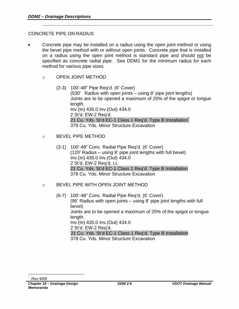
CONCRETE PIPE ON RADIUS Concrete pipe may be installed on a radius using the open joint method or using
the bevel pipe method with or without open joints. Concrete pipe that is installed on a radius using the open joint method is standard pipe and should not be specified as concrete radial pipe. See DDM1 for the minimum radius for each method for various pipe sizes.
o OPEN JOINT METHOD
(2-3) 100’-48” Pipe Req’d. (6’ Cover)
(530’ Radius with open joints – using 8’ pipe joint lengths) Joints are to be opened a maximum of 25% of the spigot or tongue length. Inv.(In) 435.0 Inv.(Out) 434.0 2 St’d. EW-2 Req’d.
21 Cu. Yds. St’d EC-1 Class 1 Req’d. Type B Installation* 378 Cu. Yds. Minor Structure Excavation
o BEVEL PIPE METHOD
(3-1) 100’-48” Conc. Radial Pipe Req’d. (6’ Cover)
(120’ Radius – using 8’ pipe joint lengths with full bevel) Inv.(In) 435.0 Inv.(Out) 434.0 2 St’d. EW-2 Req’d. Lt.
21 Cu. Yds. St’d EC-1 Class 1 Req’d. Type B Installation 378 Cu. Yds. Minor Structure Excavation
o BEVEL PIPE WITH OPEN JOINT METHOD
(6-7) 100’-48” Conc. Radial Pipe Req’d. (6’ Cover)
(95’ Radius with open joints – using 8’ pipe joint lengths with full bevel) Joints are to be opened a maximum of 25% of the spigot or tongue length. Inv.(In) 435.0 Inv.(Out) 434.0 2 St’d. EW-2 Req’d.
21 Cu. Yds. St’d EC-1 Class 1 Req’d. Type B Installation 378 Cu. Yds. Minor Structure Excavation
* Rev 9/09

DDM2 – Drainage Descriptions
VDOT Drainage Manual DDM 2-7 Chapter 15 – Drainage Design Memoranda
JACKED PIPE
(5-6) 80’-48” Jacked Conc. Pipe Req’d. (25’ Cover) Inv.(In) 197.6 Inv.(Out) 197.0 2 St’d. EW-2 Req’d. 21 Cu. Yds. St’d EC-1 Class 1 Req’d. Type B Installation*
MULTIPLE PIPE INSTALLATION
(8-9) 300’-48” Pipe Req’d. (7’ Cover) (Triple Line – 100’ each line) Inv.(In) 164.8 Inv.(Out) 164.1 2 St’d. EW-7 Req’d. 41 Cu. Yds. St’d EC-1 Class 1 Req’d. Type B Installation
1,134 Cu. Yds. Minor Structure Excavation
EXISTING PIPE EXTENSION The vertical and horizontal alignment of the pipe extension should duplicate that
of the existing pipe. The type of pipe specified for the extension should be the same as the existing pipe. The cover specified should be the maximum that occurs along the entire run of pipe, including the existing section.
(2-3) Existing Pipe To Be Extended with 50’-36” Corrugated Steel Pipe Req’d.
(7’ Cover) Inv.(In) 435.0 Inv.(Out) 434.0 1 St’d. EW-1 Req’d.
STORM SEWER PIPE
Pipe that is considered storm sewer pipe is to be so designated in the plan description.
(2-3) T0 (3-3) 195’-24” Storm Sewer Pipe Req’d. (11’ Cover)
Inv.(In) 15.2 Inv.(Out) 14.5
BOX CULVERT DESCRIPTIONS
* Rev 9/09
DDM2 – Drainage Descriptions
Chapter 15 – Drainage Design Memoranda
DDM 2-8 VDOT Drainage Manual
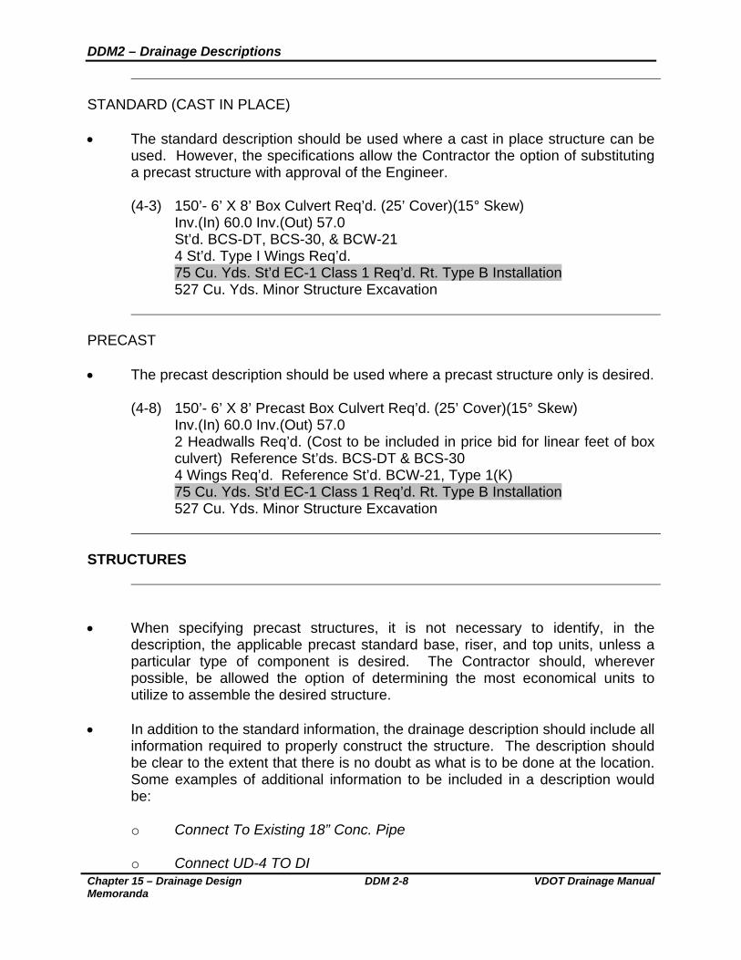
STANDARD (CAST IN PLACE) The standard description should be used where a cast in place structure can be
used. However, the specifications allow the Contractor the option of substituting a precast structure with approval of the Engineer.
(4-3) 150’- 6’ X 8’ Box Culvert Req’d. (25’ Cover)(15° Skew)
Inv.(In) 60.0 Inv.(Out) 57.0 St’d. BCS-DT, BCS-30, & BCW-21 4 St’d. Type I Wings Req’d.
75 Cu. Yds. St’d EC-1 Class 1 Req’d. Rt. Type B Installation 527 Cu. Yds. Minor Structure Excavation
PRECAST The precast description should be used where a precast structure only is desired.
(4-8) 150’- 6’ X 8’ Precast Box Culvert Req’d. (25’ Cover)(15° Skew) Inv.(In) 60.0 Inv.(Out) 57.0
2 Headwalls Req’d. (Cost to be included in price bid for linear feet of box culvert) Reference St’ds. BCS-DT & BCS-30
4 Wings Req’d. Reference St’d. BCW-21, Type 1(K) 75 Cu. Yds. St’d EC-1 Class 1 Req’d. Rt. Type B Installation 527 Cu. Yds. Minor Structure Excavation
STRUCTURES
When specifying precast structures, it is not necessary to identify, in the
description, the applicable precast standard base, riser, and top units, unless a particular type of component is desired. The Contractor should, wherever possible, be allowed the option of determining the most economical units to utilize to assemble the desired structure.
In addition to the standard information, the drainage description should include all
information required to properly construct the structure. The description should be clear to the extent that there is no doubt as what is to be done at the location. Some examples of additional information to be included in a description would be:
o Connect To Existing 18” Conc. Pipe
o Connect UD-4 TO DI

DDM2 – Drainage Descriptions
VDOT Drainage Manual DDM 2-9 Chapter 15 – Drainage Design Memoranda
Standard IS-1 Inlet Shaping should be specified for manholes, drop inlets, or
junction boxes where the main trunk line of a storm sewer changes direction or pipes of approximately the same size intersect and are carried forward in a single pipe.
Standard SL-1 safety slabs shall be specified for manholes, drop inlets, or
junction boxes in accordance with the guidance outlined in DDM1 and the standard drawing.
All drop inlets (both curb and median), catch basins, junction boxes and other such structures that require a frame and cover or grate at finished ground elevation, shall show the height dimension “H” on the plans and on the Drainage Summary. This dimension is to be measured from the invert elevation to the top of the concrete or masonry structure and is to be shown to the nearest 0.1 foot.
Manholes should be shown as the number of linear feet required, measured from
the invert to the top of the concrete or masonry structure. The linear feet of manhole specified should not include the height of the frame and cover.
CURB DROP INLETS The standard description assumes cast in place; however, the Contractor is
allowed the option to substitute a precast structure. (3-1) 1 St’d. DI-4D Req’d.
L=8’, H=5.2’ Inv. 197.6 St’d. IS-1 Req’d.
When the required structure height is greater than the maximum allowed for a
cast in place structure, or a precast structure is desired, the description would be:
(9-7) 1 St’d. DI-4DD (Precast) Req’d. L=8’, H=25.0’ Inv. 197.6 2 St’d. SL-1 Req’d.
GRATE DROP INLETS Descriptions for Standard DI-5, DI-7, and DI-12 series grate drop inlets should
specify the type of grate required, i.e., a Type I grate for areas where pedestrian access is unlikely or a Type III (DI-5 & 7) or Type II (DI-12) for pedestrian accessible areas. When a DI-7 inlet is to be located in areas subject to occasional traffic (e.g., shoulders, parking areas, etc.), a load carrying Grate B should be specified. (9-16) 1 St’d. DI-7 Req’d. Grate A Type II Req’d.

DDM2 – Drainage Descriptions
Chapter 15 – Drainage Design Memoranda
DDM 2-10 VDOT Drainage Manual
H=5.3’ Inv. 23.6 Descriptions for Standard DI-5 inlets should include the type of cover. The
Standard PG-2A cover type most closely matching the ditch configuration should be specified. The height of the structure is measured from the invert to the top of the concrete cover. (4-5) 1 St’d. DI-5 Req’d. Type I Grate Req’d.
St’d. PG-2A Type E Cover H=4.8’ Inv. 13.6
MANHOLES If a cast in place structure only is to be allowed, show only the MH-1 designation.
Show only the MH-2 designation if a precast unit only is to be allowed. The option of utilizing cast in place as well as precast manholes should be allowed at all locations except for those where placement is limited due to existing pipelines, utilities, the size of pipe, etc. Most locations should permit the Contractor the option to utilize either and the descriptions should specify both the cast in place and precast standard. (3-1) 14.6 Lin. Ft. St’d. MH-1 or 2 Req’d.
1 St’d. MH-1 Frame & Cover Req’d. Inv. 83.4 1 St’d. SL-1 Req’d.
JUNCTION BOXES
(8-3) 1 St’d. JB-1 Req’d. H=12.8’, W=4’, D=5’ Type A Tower Req’d.
1 St’d. MH-1 Frame & Cover Req’d. Inv. 121.4 1 St’d. SL-1 Req’d.
STORMWATER MANAGEMENT STRUCTURES In those instances where the stormwater management basin is to be utilized as a
temporary sediment basin, the description should be so noted with a reference to Standard SWM-DR for details.

DDM2 – Drainage Descriptions
VDOT Drainage Manual DDM 2-11 Chapter 15 – Drainage Design Memoranda
o SWM DRAINAGE STRUCTURE
(14-7) 6.7’ St’d. SWM-1 Req’d.
Bottom Elev. 23.8 3” Diameter Water Quality Orifice Req’d., Inv. 26.8 10” Diameter Orifice Req’d., Inv. 28.8 See Sheet 2G For Details.
o STORMWATER MANAGEMENT DAM
(11-9) 1 SWM Dam Req’d. See sheet 2E for details.
o MANUFACTURED WATER QUALITY STRUCTURES
(7-7) 1 Water Quality Structure Req’d.
Top Elevation 26.3 Inv. Pipe (In) 20.3, Inv. Pipe (Out) 20.0 Minimum WQV=2,345 Cu. Ft. Minimum WQQ=8.5 CFS
EXISTING STRUCTURES “Modify” should be used when a major work effort is required (e.g., connecting or
removing pipes, adjusting height more than 1 foot, etc.).
(4-11) Modify Existing Drop Inlet Adjust To Grade. Raise 2.3’ Add DI-3B, L=6’ Top. Proposed Top Elev. 153.6 See Sheet 2K For Details.
“Adjust” should be used when a minor work effort is required (e.g., adjusting
height 1 foot or less).
(5-18) Adjust Existing MH Adjust To Grade. Raise 0.5’ 1 St’d. MH-1 Frame & Cover Req’d. Proposed Top Elev. 234.3 All work to be performed to modify the structure should be clearly stated in the
drainage description. Other such information would be:
o Modify To (Accept/Remove) 15” Conc. Pipe o Connect UD-4 To Structure

DDM2 – Drainage Descriptions
Chapter 15 – Drainage Design Memoranda
DDM 2-12 VDOT Drainage Manual
o Convert Existing DI to Manhole
o To Be Cleaned Out
The necessary standard items for completing the work should be specified (e.g.,
precast units, manhole frame and cover, etc.). The structural condition of an existing structure should be field evaluated to determine the suitability for modification. Those structures found to be structurally deficient or in poor condition should be replaced in lieu of being modified. The cost of total replacement versus modification should also be evaluated to make sure the most economical solution is being proposed.

DDM3 – Minor Structure Excavation
VDOT Drainage Manual DDM 3-1 Chapter 15 – Drainage Design Memoranda
VIRGINIA DEPARTMENT OF TRANSPORTATION
LOCATION AND DESIGN DIVISION
DRAINAGE DESIGN MEMORANDUM GENERAL SUBJECT:
MINOR STRUCTURE EXCAVATION
NUMBER: DDM 3.1
Date: September 1, 2005
SPECIFIC SUBJECT: Measurement of Excavation for Pipe and Box Culverts and Appurtenances
SUPERSEDES: DDM3 & IIM-LD-91 (D) 71.8
ADMINISTRATOR APPROVAL: R. T. Mills State Hydraulics Engineer
POLICY
Quantities for minor structure excavation will be computed for pipes and box
culverts with a diameter or span of 48 inch and larger. For multiple pipe installations, the span is measured between the interiors of the outside walls of the outer most pipes and is measured along a line perpendicular to the barrel of the pipe. Minor structure excavation will be computed to a point 18 inches outside the periphery of the barrel section, or to a point bound by vertical planes coincident with the bedding limits shown on the Standard PB-1 drawings.
The minor structure excavation quantity for wingwalls and other appurtenances
will be based on the “ratio” of the plan area of the wingwalls or appurtenances to the plan area of the barrel.
PROCEDURE
For single line culverts, the width of the barrel will be the nominal span or
opening of the pipe or box culvert; for multiple spans, the barrel width will be the overall distance between inner faces of the outermost barrel openings. This dimension is defined by the S+2D value noted on the standard drawings for endwalls for multiple barrel culverts in the Road and Bridge Standards. The length of all culverts will be from end to end of the culvert. The outside wall thickness and the 18 inches outside the neatlines of the periphery of the culvert are not to be included in the computing the “ratio.”
DDM3 – Minor Structure Excavation
Once the “ratio” has been determined, it is used to compute the total cubic yards
of Minor Structure Excavation for the structure and appurtenances, by using the excavation quantity for the barrel section and increasing this quantity by the “ratio.”
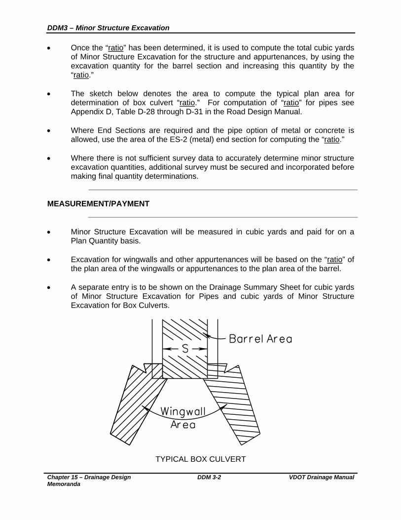
The sketch below denotes the area to compute the typical plan area for
determination of box culvert “ratio.” For computation of “ratio” for pipes see Appendix D, Table D-28 through D-31 in the Road Design Manual.
Where End Sections are required and the pipe option of metal or concrete is
allowed, use the area of the ES-2 (metal) end section for computing the “ratio.” Where there is not sufficient survey data to accurately determine minor structure
excavation quantities, additional survey must be secured and incorporated before making final quantity determinations.
MEASUREMENT/PAYMENT
Minor Structure Excavation will be measured in cubic yards and paid for on a
Plan Quantity basis. Excavation for wingwalls and other appurtenances will be based on the “ratio” of
the plan area of the wingwalls or appurtenances to the plan area of the barrel. A separate entry is to be shown on the Drainage Summary Sheet for cubic yards
of Minor Structure Excavation for Pipes and cubic yards of Minor Structure Excavation for Box Culverts.
TYPICAL BOX CULVERT
Chapter 15 – Drainage Design Memoranda
DDM 3-2 VDOT Drainage Manual

DDM4 – Drainage Design at Railroads
VDOT Drainage Manual DDM 4-1 Chapter 15 – Drainage Design Memoranda
VIRGINIA DEPARTMENT OF TRANSPORTATION
LOCATION AND DESIGN DIVISION
DRAINAGE DESIGN MEMORANDUM
GENERAL SUBJECT: DRAINAGE DESIGN AT RAILROADS
NUMBER: DDM4
DATE: September 1, 2005
SPECIFIC SUBJECT: GUIDELINES AND CRITERIA FOR DRAINAGE DESIGN UNDER OR ADJACENT TO RAILROADS
SUPERSEDES:
IIM-LD- 229
ADMINISTRATOR APPROVAL: R. T. Mills State Hydraulics Engineer
________________________________________________________________
OVERVIEW
________________________________________________________________ On VDOT projects, where there is a need to install a culvert or a storm sewer
pipe within railroad right of way, either under or adjacent to the tracks, the Hydraulic Engineer should contact the Department of Rail and Public Transportation to determine the specific design and construction criteria required by the Railroad Company and to initiate the process for obtaining any approvals needed from the Railroad Company. Railroad Companies generally follow engineering practices recommended by the American Railway Engineering and Maintenance-of-Way Association (AREMA) in their Manual of Recommended Practices for Railway Engineering, Volume I, Chapters 4 & 5. Railroad Companies reserve the authority to adopt and use more stringent design requirements, as they deem necessary. Some of the basic criteria for culverts and storm sewers that are to be located on railroad right of way are presented in this memorandum.
Projects that have railroad involvement generally are not advertised for
construction until the Rail/Highway Agreement is fully executed. The execution of the Agreement by the Railroad Company is contingent upon their review and acceptance of the project design, especially the drainage design, as it relates to or affects their facilities. It is important that the Railroad Company be provided a complete and current set of plans and drainage computations for their review. The plan review and comment period by the Railroad Company can typically take three months or more for each submittal. Many projects take two or more reviews to address comments or correct plan omissions or errors. The time needed for review and coordination with the Railroad Company should be taken into consideration when establishing project schedules.

DDM4 – Drainage Design at Railroads
Chapter 15 – Drainage Design Memoranda
DDM 4-2 VDOT Drainage Manual
________________________________________________________________ CRITERIA
________________________________________________________________ HYDRAULIC DESIGN CRITERIA Culvert design follows the same FHWA methods used for VDOT highway
projects with the following minimum criteria:
o The 25 year discharge shall produce a headwater elevation at the culvert entrance no greater than the top of the pipe (HW/D = 1.0).
o The 100 year discharge shall produce a headwater elevation at the culvert
entrance no greater than 1.5 times the height of the culvert (HW/D = 1.5) or 2.0’ below the elevation of the bottom of the rail, whichever is less.
Where field conditions do not permit installation of pipes sizes meeting this
criteria, “pre and post construction ” computations must be provided showing the headwater elevations for the 25 year and 100 year floods and demonstrating that there will be no increase in headwater depth due to the proposed construction. The Engineering Department of the Railroad Company must approve such designs. ________________________________________________________________
PIPE SIZE AND COVER The minimum pipe size for use under the track is 36” diameter. A smaller size
pipe may be allowed with the approval of the engineering department of the railroad.
The maximum pipe size for use under the track is 72” diameter. A larger size
pipe may be allowed with the approval of the engineering department of the railroad.
The minimum pipe cover is to be 5.5’ as measured from the outside top of the
pipe (casing pipe if used) to the bottom of the rail. Since survey crews often obtain the elevation of the top of the rail, an assumed rail height of 7 ½” may be used in determining the elevation of the bottom of the rail. Cover may also be determined by using the top of the cross tie elevation if the top of the rail elevation is unknown. In locations where the minimum cover cannot be obtained, a request must be made to the Railroad Company for an exception, with a complete explanation of the need for the exception.
DDM4 – Drainage Design at Railroads
VDOT Drainage Manual DDM 4-3 Chapter 15 – Drainage Design Memoranda
PIPE MATERIALS AND INSTALLATION
________________________________________________________________ Pipes to be installed under existing tracks will generally require the bore and jack
or tunneling method of installation and must be so noted on the construction plans. An exception to this may be granted by the Railroad Company for spur tracks or tracks with infrequent use. Special circumstances, such as minimum cover, or other restrictions may sometimes necessitate that a pipe or box culvert be installed by the open cut method. These sites should be carefully reviewed by VDOT, the Department of Rail and Public Transportation and the Railroad Company to decide the appropriate methods and materials to be specified in the construction plans.
o SMOOTH WALL STEEL PIPE
- The Railroad Company’s standard pipe material for the bore and
jack installation method is smooth wall steel pipe capable of supporting the Cooper E-80 loading. A structural analysis that is consistent with the Cooper E-80 loading requirements must be available for the Railroad Company’s review and approval should they desire. Section 105 of the Road and Bridge Specifications outlines the procedures that should be followed for this process.
- The smooth wall steel pipe may function as the carrier pipe (i.e.,
used to convey the stormwater run-off) or function as a casing pipe for the actual carrier pipe. If installed as the carrier pipe, the smooth wall steel pipe must conform to the criteria set forth in the appropriate notes for uncoated galvanized steel pipe shown in Table A & A1 of the “Allowable Pipe Criteria for Culverts and Storm Sewers” in Standard PC-1 of the Road and Bridge Standards. The State Location and Design Engineer and the District Materials Engineer must approve any deviation from the noted criteria. The drainage description for smooth wall steel pipes installed under the railroad by the bore and jack method should specify:
Jacked Smooth Wall Steel Pipe Req’d. Pipe shall be designed to support Cooper E-80 loading in accordance with Section 105 of the Road and Bridge Specifications and installed by the bore and jack method. Smooth wall steel pipe shall have a minimum wall thickness of (See Table A).
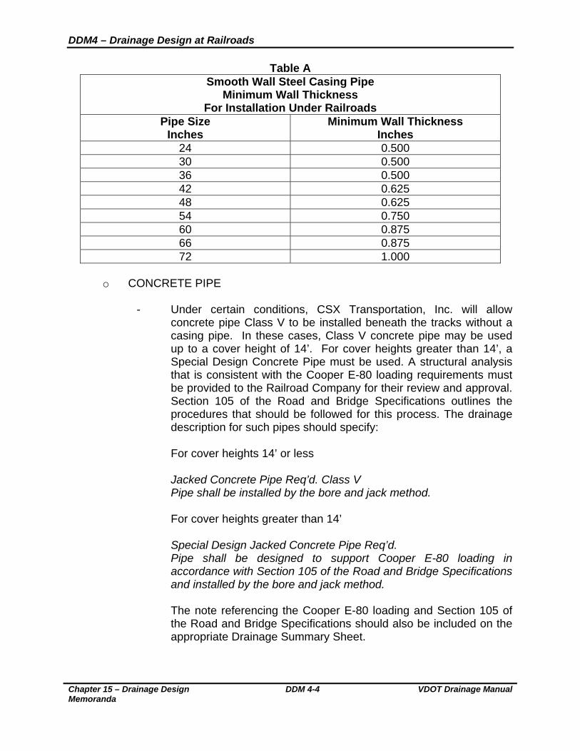
DDM4 – Drainage Design at Railroads
Chapter 15 – Drainage Design Memoranda
DDM 4-4 VDOT Drainage Manual
Table A
Smooth Wall Steel Casing Pipe Minimum Wall Thickness
For Installation Under Railroads Pipe Size
Inches Minimum Wall Thickness
Inches 24 0.500 30 0.500 36 0.500 42 0.625 48 0.625 54 0.750 60 0.875 66 0.875 72 1.000
o CONCRETE PIPE
- Under certain conditions, CSX Transportation, Inc. will allow
concrete pipe Class V to be installed beneath the tracks without a casing pipe. In these cases, Class V concrete pipe may be used up to a cover height of 14’. For cover heights greater than 14’, a Special Design Concrete Pipe must be used. A structural analysis that is consistent with the Cooper E-80 loading requirements must be provided to the Railroad Company for their review and approval. Section 105 of the Road and Bridge Specifications outlines the procedures that should be followed for this process. The drainage description for such pipes should specify:
For cover heights 14’ or less
Jacked Concrete Pipe Req’d. Class V Pipe shall be installed by the bore and jack method.
For cover heights greater than 14’ Special Design Jacked Concrete Pipe Req’d. Pipe shall be designed to support Cooper E-80 loading in accordance with Section 105 of the Road and Bridge Specifications and installed by the bore and jack method.
The note referencing the Cooper E-80 loading and Section 105 of the Road and Bridge Specifications should also be included on the appropriate Drainage Summary Sheet.
DDM4 – Drainage Design at Railroads
VDOT Drainage Manual DDM 4-5 Chapter 15 – Drainage Design Memoranda
O CORRUGATED STEEL PIPE
- For pipes to be installed under proposed or relocated tracks to be constructed on a new location, the open cut method of installation should be used. The pipe material generally accepted by the Railroad Company for this type of installation is corrugated steel capable of supporting the Cooper E-80 loading requirements. Aluminized Type 2 or Polymer Coated are the standard types of corrugated steel pipe allowed by VDOT. A structural analysis that is consistent with the Cooper E-80 loading requirements must be available for the Railroad Company’s review and approval should they desire. Section 105 of the Road and Bridge Specifications outlines the procedures that should be followed for this process. The drainage description for such pipes should specify:
Corrugated Steel Pipe Req’d. Pipe shall be designed to support Cooper E-80 loading in accordance with Section 105 of the Road and Bridge Specifications.
- The note referencing the Cooper E-80 loading and Section 105 of
the Road and Bridge Specifications should also be included on the appropriate Drainage Summary Sheet. For locations where VDOT does not normally allow corrugated steel pipe (see Allowable Pipe Type Tables in Standard PC-1 of the Road and Bridge Standards), concern should be expressed to the Railroad Company about the use of this type of pipe material. Railroad Companies generally require that VDOT own and maintain any drainage structures that VDOT installs on railroad right of way. Therefore, we should endeavor to use the type of material that has proven to provide an appropriate life expectancy for specific site conditions. However, the Railroad Company will have final approval on the type of material and the installation method.
________________________________________________________________ DROP INLETS Drop inlets should generally not be located on the railroad right of way. When
determined necessary to locate drop inlets on railroad right of way, they should be located no closer than 18’ from the track centerline. Railroads have a responsibility to their employees and customers to provide a hazard free operating corridor and are concerned with the hazard potential presented by grate inlets, especially those located in ditches. Any grate inlet that must be located within 18’ from the track centerline, or in an area where there is concern with a hazard potential due to grate openings, should have the bar spacing of the grates specified as would be required for pedestrian accessible areas. Where a Standard DI-5 or DI-7 inlet is proposed in these areas, a Type III grate shall be specified.

DDM4 – Drainage Design at Railroads
Chapter 15 – Drainage Design Memoranda
DDM 4-6 VDOT Drainage Manual
________________________________________________________________ DITCHES Drainage ditches on railroad right of way that will convey VDOT roadway or
bridge deck run off must be analyzed for the effects of the 100 year frequency discharge. This does not necessarily mean that the ditch must contain the 100 year storm but rather the effects of the 100 year storm must be documented. The analysis must be submitted to the Engineering Department of the Railroad Company for their review and approval. The analysis should present a factual scenario that is clear and easily understood. A computer printout that is not clearly presented or explained is not usually acceptable to the Railroad Company. ________________________________________________________________
FOUNDATIONS FOR SIGNALS The location of proposed drainage structures may conflict with the foundations of
proposed Railroad Company installed warning devices at rail crossings. The location of the warning device is prescribed by federal regulations and varies according to the typical section of the roadway and the alignment of the rail crossing. The location of proposed drainage structures in these areas should be reviewed with the Department of Rail and Public Transportation to determine any possible conflicts. ________________________________________________________________
ENDWALLS AND OTHER STRUCTURES For construction detail requirements when placing pipe endwalls, manholes and
other such structures adjacent to railroads, see Section 2E-24 of the VDOT Road Design Manual.
________________________________________________________________
GUIDELINES
________________________________________________________________ The following general guidelines are presented to assist the Drainage Designer
in developing a design that is acceptable to the Railroad Company. These guidelines are representative of the comments received from Railroad Companies on past VDOT projects. o For projects that are rebuilding an existing crossing, the existing drainage
patterns should not be altered and documentation (a narrative with hydrologic and hydraulic computations) should be provided to the Railroad Company that indicates no increase in volume, velocity or flow depth/headwater depth is caused by the project on railroad right of way.

DDM4 – Drainage Design at Railroads
VDOT Drainage Manual DDM 4-7 Chapter 15 – Drainage Design Memoranda
o Railroad Companies do not generally allow new drainage outfalls to discharge onto railroad right of way. Any existing outfall that is to be replaced or altered should be acceptable provided the documentation as previously noted for volume, velocity and flow depth/headwater depth is provided to the Railroad Company.
o When a constructed outfall (ditch or pipe) must be directed into a railroad
ditch paralleling the rail bed, the constructed ditch or pipe should intersect the railroad ditch at an angle, in lieu of perpendicular, in order to lessen concerns with potential erosion. The appropriate erosion control measures should be applied at the intersection point to ensure stability of the rail bed and the existing railroad ditch.
o Proposed storm drain pipes paralleling the railroad tracks are not generally
permitted to occupy the railroad right of way. o Proposed roadway culverts and storm drains are not generally permitted to
connect to existing railroad culverts. For situations where such a connection is unavoidable, the Railroad Company usually requires that VDOT assume maintenance responsibility for the railroad culvert.
o Scuppers, deck drains, drop inlets or other concentrated flow outlets from
bridge decks are generally not allowed to drain directly onto the railroad right of way.
o Primary and emergency spillways and outfall structures of stormwater
management basins, as well as the basin itself, are generally not allowed to be located on the railroad right of way. Where flow from a stormwater management basin is directed onto railroad right of way, documentation should be provided to the Railroad Company that indicates no increase in volume, velocity or flow depth/headwater depth is caused by the project on railroad right of way.
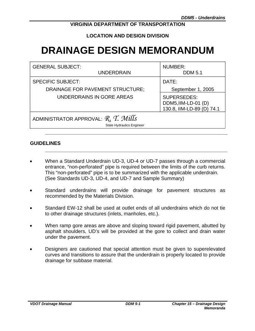
DDM5 - Underdrains
VDOT Drainage Manual DDM 5-1 Chapter 15 – Drainage Design Memoranda
VIRGINIA DEPARTMENT OF TRANSPORTATION
LOCATION AND DESIGN DIVISION
DRAINAGE DESIGN MEMORANDUM
GENERAL SUBJECT: UNDERDRAIN
NUMBER: DDM 5.1
DATE:
September 1, 2005
SPECIFIC SUBJECT:
DRAINAGE FOR PAVEMENT STRUCTURE;
UNDERDRAINS IN GORE AREAS SUPERSEDES: DDM5,IIM-LD-01 (D) 130.8, IIM-LD-89 (D) 74.1
ADMINISTRATOR APPROVAL: R. T. Mills State Hydraulics Engineer
GUIDELINES
When a Standard Underdrain UD-3, UD-4 or UD-7 passes through a commercial
entrance, “non-perforated” pipe is required between the limits of the curb returns. This “non-perforated” pipe is to be summarized with the applicable underdrain. (See Standards UD-3, UD-4, and UD-7 and Sample Summary)
Standard underdrains will provide drainage for pavement structures as
recommended by the Materials Division. Standard EW-12 shall be used at outlet ends of all underdrains which do not tie
to other drainage structures (inlets, manholes, etc.). When ramp gore areas are above and sloping toward rigid pavement, abutted by
asphalt shoulders, UD’s will be provided at the gore to collect and drain water under the pavement.
Designers are cautioned that special attention must be given to superelevated
curves and transitions to assure that the underdrain is properly located to provide drainage for subbase material.

DDM5 - Underdrains
Chapter 15 – Drainage Design Memoranda
DDM 5-2 VDOT Drainage Manual
DESIGN PROCEDURES
The Roadway Designer will submit Form LD-252 to the Materials Division,
requesting preliminary pavement design and underdrain type and location recommendations. Form LD-252 will be submitted during the early stages of project development so that the requested information will be available to the Drainage Designer during the drainage design phase prior to the Field Inspection.
The Materials Division will provide the Roadway Designer with recommendations
for the preliminary pavement design and the type and location of underdrains for the project. Underdrain recommendations will include Standard UD-2, UD-4, UD-5, UD-6 and/or UD-7 underdrains, as appropriate. Recommendations will include Standard UD-1 underdrains when sufficient data exists to determine locations.
Prior to submitting a request to the Hydraulics Unit for drainage design, the
Roadway Designer will depict the underdrains on the drainage layer of the electronic files and /or hard copy of the plans at the locations recommended by the Materials Division. The Roadway Designer will depict only those underdrains that parallel the roadway centerline. A copy of the Materials Division’s report will be included in the data forwarded to the Hydraulics Unit with the request for the drainage design.
The Roadway Designer will depict Standard UD-3 Sidewalk Underdrains on the
drainage layer of the electronic files and/or hard copy of the plans at the locations recommended by the District Construction Engineer.
The Drainage Designer will:
o Determine the locations for CD-1 or CD-2’s at:
- Down grade end of cut to fill transitions. - Sag points in roadway grade. - Bridge approach slabs.
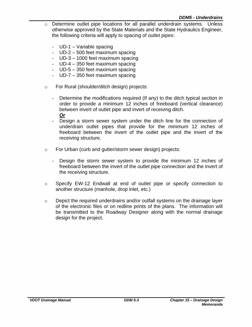
DDM5 - Underdrains
VDOT Drainage Manual DDM 5-3 Chapter 15 – Drainage Design Memoranda
o Determine outlet pipe locations for all parallel underdrain systems. Unless otherwise approved by the State Materials and the State Hydraulics Engineer, the following criteria will apply to spacing of outlet pipes:
- UD-1 – Variable spacing - UD-2 – 500 feet maximum spacing - UD-3 – 1000 feet maximum spacing - UD-4 – 350 feet maximum spacing - UD-5 – 350 feet maximum spacing - UD-7 – 350 feet maximum spacing
o For Rural (shoulder/ditch design) projects:
- Determine the modifications required (If any) to the ditch typical section in
order to provide a minimum 12 inches of freeboard (vertical clearance) between invert of outlet pipe and invert of receiving ditch. Or
- Design a storm sewer system under the ditch line for the connection of underdrain outlet pipes that provide for the minimum 12 inches of freeboard between the invert of the outlet pipe and the invert of the receiving structure.
o For Urban (curb and gutter/storm sewer design) projects:
- Design the storm sewer system to provide the minimum 12 inches of
freeboard between the invert of the outlet pipe connection and the invert of the receiving structure.
o Specify EW-12 Endwall at end of outlet pipe or specify connection to
another structure (manhole, drop inlet, etc.)
o Depict the required underdrains and/or outfall systems on the drainage layer of the electronic files or on redline prints of the plans. The information will be transmitted to the Roadway Designer along with the normal drainage design for the project.
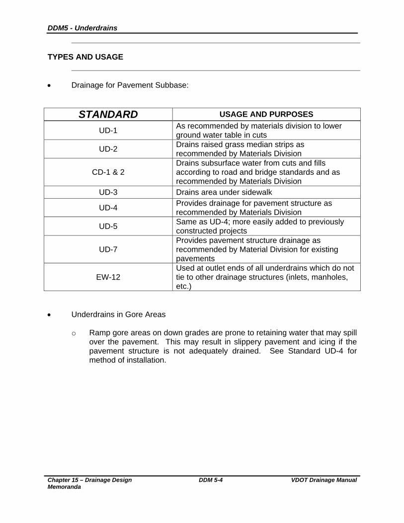
DDM5 - Underdrains
Chapter 15 – Drainage Design Memoranda
DDM 5-4 VDOT Drainage Manual
TYPES AND USAGE
Drainage for Pavement Subbase:
STANDARD USAGE AND PURPOSES
UD-1 As recommended by materials division to lower ground water table in cuts
UD-2 Drains raised grass median strips as recommended by Materials Division
CD-1 & 2 Drains subsurface water from cuts and fills according to road and bridge standards and as recommended by Materials Division
UD-3 Drains area under sidewalk
UD-4 Provides drainage for pavement structure as recommended by Materials Division
UD-5 Same as UD-4; more easily added to previously constructed projects
UD-7 Provides pavement structure drainage as recommended by Material Division for existing pavements
EW-12 Used at outlet ends of all underdrains which do not tie to other drainage structures (inlets, manholes, etc.)
Underdrains in Gore Areas
o Ramp gore areas on down grades are prone to retaining water that may spill
over the pavement. This may result in slippery pavement and icing if the pavement structure is not adequately drained. See Standard UD-4 for method of installation.
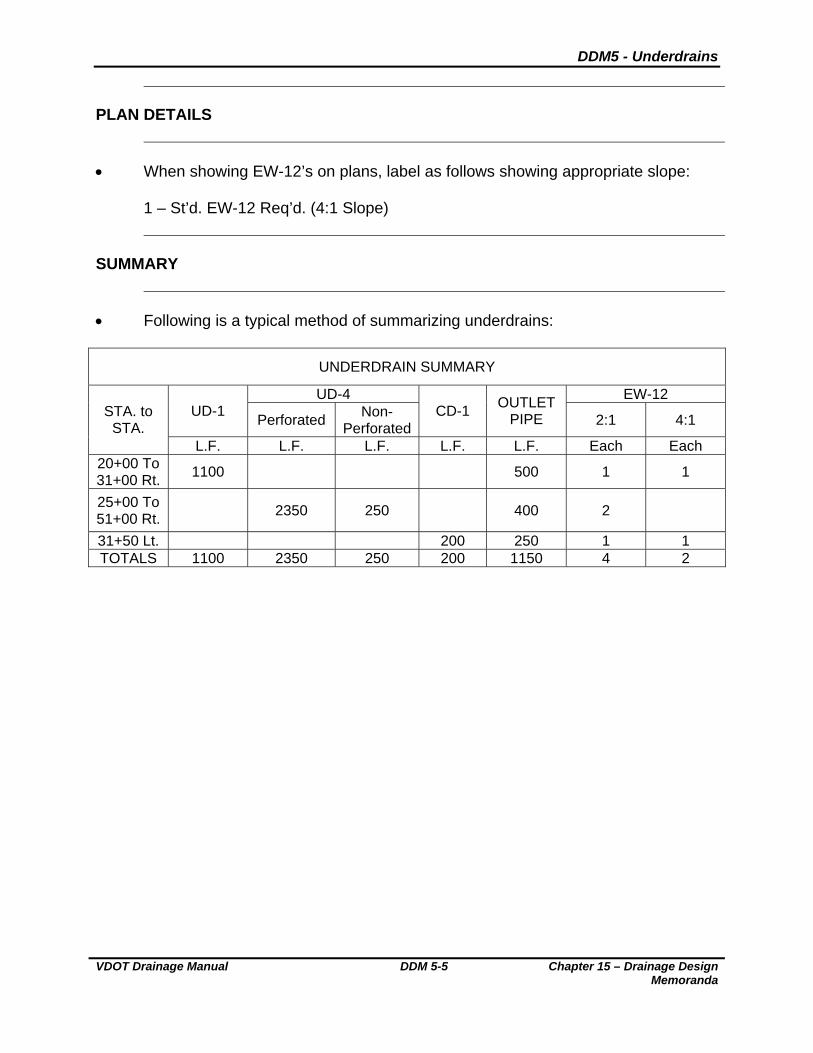
DDM5 - Underdrains
VDOT Drainage Manual DDM 5-5 Chapter 15 – Drainage Design Memoranda
PLAN DETAILS
When showing EW-12’s on plans, label as follows showing appropriate slope:
1 – St’d. EW-12 Req’d. (4:1 Slope)
SUMMARY
Following is a typical method of summarizing underdrains:
UNDERDRAIN SUMMARY
UD-4 EW-12 UD-1
Perforated Non-
PerforatedCD-1
OUTLET PIPE 2:1 4:1
STA. to STA.
L.F. L.F. L.F. L.F. L.F. Each Each 20+00 To 31+00 Rt.
1100 500 1 1
25+00 To 51+00 Rt.
2350 250 400 2
31+50 Lt. 200 250 1 1 TOTALS 1100 2350 250 200 1150 4 2

DDM6 – CTB Cost Participation Policy
VDOT Drainage Manual DDM 6-1 Chapter 15 – Drainage Design Memoranda
VIRGINIA DEPARTMENT OF TRANSPORTATION
LOCATION AND DESIGN DIVISION
DRAINAGE DESIGN MEMORANDUM
GENERAL SUBJECT: BOARD POLICIES ON PARTICIPATION BY TOWNS,
CITIES AND COUNTIES
NUMBER: DDM 6
SPECIFIC SUBJECT:
DATE: March 23, 1988
SUPERSEDES: LD-83 (D) 146.1
Attached for your information and use is the policy revision, pertaining to state and local participation in the cost of right of way, sidewalks, utility adjustments, and storm sewers on improvements to the state’s highway systems, that was adopted by the Commonwealth Transportation Board on February 18, 1998, and became effective upon adoption Section 1.00 of this policy is applicable to the SECONDARY SYSTEM PROJECTS IN COUNTIES AND TOWNS OF UNDER 3,500 POPULATION. This revision provides the following principal changes on secondary system projects:
Permits the right of way cost for sidewalks, where justified, to be borne by secondary construction allocations for the county.
Where the Department determines the utilization of curb and gutter
project’s construction as the most economical design, the cost of the necessary storm sewer and appurtenances may be borne by secondary construction allocations for the county.
Required right of way acquisition costs for projects within towns
operating under Sections 33.1-79 and 33.1-82, Code of Virginia, may be provided from the secondary construction allocations for the county, in the same manner as previously permitted for projects situated beyond the corporate limits of such towns.
All justification and/or design determination studies are to be
documented in the project file.
DDM6 – CTB Cost Participation Policy
Chapter 15 – Drainage Design Memoranda
DDM 6-2 VDOT Drainage Manual
Section 2.00 of this policy is applicable to the PRIMARY AND URBAN SYSTEMS WITHIN THE CORPORATE LIMITS OF CITIES AND TOWNS operating under the provisions of Sections 33.1-23.2, 33.1-23.3 and 33.1-44. Code of Virginia, as amended. The revision provides the following principal changes:
It provides a uniform method for determining drainage participation costs within incorporated cities and towns without regard to population.
Where storm sewer outfalls are constructed outside of the normal right
of way limits and deemed necessary for adequate project drainage, the cost will be a part of the normal project rather than figured on a run-off ratio basis, provided none of the storm water conveyed is diverted from another watershed.
Provides clarification that all storm sewers and outfalls constructed
outside the normal right of way limits and deemed beyond that necessary to adequately drain the project will be financed on a run-off ratio basis.
Adopted by the Commonwealth Transportation Board of February 18, 1988.
POLICY FOR STATE PARTICIPATION IN THE COST OF
RIGHT OF WAY, SIDEWALKS AND STORM SEWERS IN COUNTIES, TOWNS AND CITIES
WHEREAS, the Commonwealth Transportation Board has previously adopted a policy for state and local participation in the costs of right of way, sidewalks, utility adjustments, and storm sewers on projects in cities, towns, and counties; and WHEREAS, changes in conditions, including revisions to the statutes of Virginia, make it advisable to amend certain provisions of this policy; NOW, THEREFORE, BE IT RESOLVED, that the attached “Policy for State
Participation in the Cost of Right of Way, Sidewalks and Storm Sewers in Counties,
Towns and Cities” on Secondary System projects in counties and towns of under 3,500
population, and on Urban and Primary System projects within the corporate limits of
cities and towns is hereby adopted; and
BE IT FURTHER RESOLVED, that the Board’s policies – adopted on August 18, 1966
and September 21, 1978, be and hereby are rescinded

DDM6 – CTB Cost Participation Policy
VDOT Drainage Manual DDM 6-3 Chapter 15 – Drainage Design Memoranda
1.00 SECONDARY SYSTEM PROJECTS IN COUNTIES AND IN TOWNS OF
UNDER 3,500 POPULATION. 1.01 The provisions of this section apply to the system of state highways in the
several counties of the state as authorized by Section 33.1-67, Code of Virginia, as amended; and those within the corporate limits of towns of less than 3,500 population which operate under the provisions of Sections 33.1-79 and 33.1-82, Code of Virginia, as amended.
1.02 Where new sidewalks are desired and justified by traffic studies or otherwise
determined by the Department as required for pedestrian safety, all right of way necessary for the construction of the sidewalks may be borne by secondary construction funds allocated for use in the county.
1.03 Where new sidewalks are desired and justified by traffic studies, one-half the
construction cost of new sidewalks shall be borne by secondary construction funds allotted for use in the county and one-half from funds other than highway funds. However, where the contemplated improvement requires the relocation of existing sidewalks, these shall be replaced and the total cost shall be borne by secondary construction funds allocated for use in the county.
1.04 Existing storm sewers shall be relocated or replaced at no cost to others;
secondary construction funds allocated for use in the county shall bear 100 percent of the cost.
1.05 Where the construction of new curb and gutter is determined by Department
engineers to be the most economical design, the cost of new storm sewers and appurtenances such as drop inlets, manholes, etc., may be borne by secondary construction funds allocated for use in the county, provided none of the storm water to be conveyed is diverted from another watershed.
1.06 Where the construction of curb and gutter within the right of way limits is desired,
or is necessary for the development of adjacent property, but is not deemed by Department engineers to be the most economical design, the cost of storm sewers and appurtenances (drop inlets, manholes and similar items) shall be financed from secondary construction funds and other sources on the basis of run-off ratios and percentages of participation as indicated below:
State: Run-off from within right of way, 100%. Run-off from areas outside the
road right of way and within the watershed common to the project, 25%. Others: Run-off from areas outside the road right of way and within the
watershed common to the project, 75%.
1.07 Diverted drainage from water sheds not common to the project shall be financed from secondary construction funds and other sources on the run-off ratios and percentages of participation as indicated below:

DDM6 – CTB Cost Participation Policy
Chapter 15 – Drainage Design Memoranda
DDM 6-4 VDOT Drainage Manual
State: Run-off from the state’s right of way within the area of the diverted
watershed, 100% Others: Run-off from all areas in the diverted watershed, exclusion of state right
of way, 100%
1.08 All storm sewer outfalls that are found necessary or desirable shall be financed from secondary construction funds and other sources on the run-off ratios and percentages of participation as indicated below:
State: Run-off from the state’s right of way within the area being drained, 100% Others: Run-off from all areas other than the state’s right of way in the area
being drained, 100%
1.09 Where, through zoning and development control ordinances, the local governing body requires participation in the off-site drainage and where their plans from an overall standpoint reasonably conform to the above-established policy, the local governing body’s plan shall become the Transportation Board’s policy for that locality.
1.10 The adjustment of utilities necessitated by the construction of sidewalk or storm
sewer will be borne by secondary construction funds, except where the utilities are located on public property which has been dedicated or acquired for street or road purposes, including uses incidental thereto, or where there are franchise or other provisions where by the utility owner is required to bear the expense of such relocation of adjustment.
1.11 Unless otherwise specified by state statute or policy of the Commonwealth
Transportation Board, all other right of way required for improvements to secondary system shall be acquired by purchase, gift, or power of eminent domain and cost thereof financed from secondary construction funds allocated for use in the county.
2.01 The provisions of this section apply to improvements in cities and towns for which
construction funds, pursuant of Sections 33.1-23.2, 33.1-23.3 and 33.1-44, Code of Virginia, as amended, are allocated.
2.02 All storm sewers, both parallel and transverse and all appurtenances, such as
drop inlets, manholes, etc., that fall within the right of way limits of urban improvement or construction projects on exiting or new locations and are considered necessary for adequate project drainage by Department engineers will be financed at the percentage required by law for the construction of the project; provided none of the storm water to be conveyed is diverted from another watershed.
DDM6 – CTB Cost Participation Policy
VDOT Drainage Manual DDM 6-5 Chapter 15 – Drainage Design Memoranda
2.03 All storm sewers and outfalls constructed outside of the normal right of way limits
of urban projects that are considered by Department engineers as necessary for adequate project drainage will be financed at the percentage required by law for the construction of the project; provided none of the storm water to be conveyed is diverted from another watershed.
2.04 All storm sewers and outfalls constructed outside of the normal right of way limits
of urban projects that are considered by Department engineers as beyond that needed to adequately drain the highway project shall be financed on a run-off ratio basis between federal and/or state funds and city or town funds.
2.05 Whenever parallel storm sewer, manholes, etc., within an urban project or outfalls beyond the right-of-way and project limits are utilized by a city or town for the conveyance of diverted storm drainage, then the cost of such storm sewers, outfalls, etc., shall be financed on a run-off ratio basis between federal and/or state funds and city or town funds.
Related Documents