Havells India Ltd is a billion-dollar-plus organization, and is one of the largest & India’s fastest growing electrical and power distribution equipment manufacturer with products ranging from Industrial & Domestic Circuit Protection Switchgear, Cables & Wires, Motors, Fans, Power Capacitors, CFL Lamps, Luminaires for Domestic, Commercial & Industrial applications, Modular Switches, & Bathfittings covering the entire gamut of household, commercial and industrial electrical needs. Havells owns some of the prestigious global brands like Crabtree, Sylvania, Concord, Luminance, Linolite, & SLI Lighting. With 91 branches / representative offices and over 8000 professionals in over 50 countries across the globe, the group has achieved rapid success in the past few years. Its 11 state-of-the-art manufacturing plants in India located at Haridwar, Baddi, Samepur Badli, Noida, Sahibabad, Faridabad, Bhiwadi, Alwar, Neemrana, and 10 state-of-the-art manufacturing plants located across Europe, Latin America & Africa churn out globally acclaimed products. Havells India Ltd is a name synonymous with excellence and expertise in the electrical industry. Its 20000 strong global distribution network is prompt to service customers. The company has acquired a number of International certifications, like CSA, KEMA, CB, CE, ASTA, CPA, SEMKO, SIRIUM (Malaysia), SPRING (Singapore), TSE (Turkey), SNI (Indonesia) and EDD (Bahrain) for various products. Today, Havells and its brands have emerged as the preferred choice of electrical products for discerning individuals and industrial consumers both in India and abroad. In an attempt to transform itself from an industrial product company to a consumer products company, Havells launched the consumer electrical products such as CFLs, Fans, Modular Switches & Luminiaires. The company has been consistent in its brand promotion with sponsorship of Cricket events like T20 World Cup, India-Australia Series and IPL. The company has also taken the initiative to reach directly to the consumers through “Havells Galaxy” – a one stop shop for all electrical and lighting needs. Social and environmental responsibility has been at the forefront of Havells operating philosophy and as a result the company consistently contributes to socially responsible activities. For instance, the company is providing mid-day meal in government schools in Alwar district, covering 15000 students per day. Besides this company has acquired land for constructing a larger kitchen with all the modern facilities to serve freshly cooked food to 50000 students in the area. Havells runs a mobile Medical Van, equipped with a trained doctor and necessary medicines in the rural areas of Delhi & NCR for the very poor and needy villagers. We also set up free medical check-up camps. In the past also, the company has generously contributed to the society during various national calamities like the Bihar Flood, Tsunami and Kargil National Relief Fund etc. The essence of Havells success lies in the expertise of its fine team of professionals, strong relationships with associates and the ability to adapt quickly and efficiently, with the vision to always think ahead.

Welcome message from author
This document is posted to help you gain knowledge. Please leave a comment to let me know what you think about it! Share it to your friends and learn new things together.
Transcript

Havells India Ltd is a billion-dollar-plus organization, and is one of the largest & India’s fastest growing electrical and power distribution equipment manufacturer with products ranging from Industrial & Domestic Circuit Protection Switchgear, Cables & Wires, Motors, Fans, Power Capacitors, CFL Lamps, Luminaires for Domestic, Commercial & Industrial applications, Modular Switches, & Bathfittings covering the entire gamut of household, commercial and industrial electrical needs.
Havells owns some of the prestigious global brands like Crabtree, Sylvania, Concord, Luminance, Linolite, & SLI Lighting.
With 91 branches / representative offices and over 8000 professionals in over 50 countries across the globe, the group has achieved rapid success in the past few years. Its 11 state-of-the-art manufacturing plants in India located at Haridwar, Baddi, Samepur Badli, Noida, Sahibabad, Faridabad, Bhiwadi, Alwar, Neemrana, and 10 state-of-the-art manufacturing plants located across Europe, Latin America & Africa churn out globally acclaimed products. Havells India Ltd is a name synonymous with excellence and expertise in the electrical industry. Its 20000 strong global distribution network is prompt to service customers.
The company has acquired a number of International certifications, like CSA, KEMA, CB, CE, ASTA, CPA, SEMKO, SIRIUM (Malaysia), SPRING (Singapore), TSE (Turkey), SNI (Indonesia) and EDD (Bahrain) for various products.
Today, Havells and its brands have emerged as the preferred choice of electrical products for discerning individuals and industrial consumers both in India and abroad.
In an attempt to transform itself from an industrial product company to a consumer products company, Havells launched the consumer electrical products such as CFLs, Fans, Modular Switches & Luminiaires. The company has been consistent in its brand promotion with sponsorship of Cricket events like T20 World Cup, India-Australia Series and IPL. The company has also taken the initiative to reach directly to the consumers through “Havells Galaxy” – a one stop shop for all electrical and lighting needs.
Social and environmental responsibility has been at the forefront of Havells operating philosophy and as a result the company consistently contributes to socially responsible activities. For instance, the company is providing mid-day meal in government schools in Alwar district, covering 15000 students per day. Besides this company has acquired land for constructing a larger kitchen with all the modern facilities to serve freshly cooked food to 50000 students in the area. Havells runs a mobile Medical Van, equipped with a trained doctor and necessary medicines in the rural areas of Delhi & NCR for the very poor and needy villagers. We also set up free medical check-up camps. In the past also, the company has generously contributed to the society during various national calamities like the Bihar Flood, Tsunami and Kargil National Relief Fund etc.
The essence of Havells success lies in the expertise of its fine team of professionals, strong relationships with associates and the ability to adapt quickly and efficiently, with the vision to always think ahead.

State-of-the-art plant
Baddi Plant
Index
Miniature Circuit Breaker 2
Residual Current Circuit Breaker (RCCB) 16A - 63A 36
Miniature Circuit Breaker (80A - 125A) 18
Residual Current Circuit Breaker (RCCB) 80A - 125A 44
MINI 24
Residual Current Circuit Breaker with Overload and Short Circuit Protection (RCBO) 48
Isolator 28
Changeover Switch 32
Distribution Board 54

2
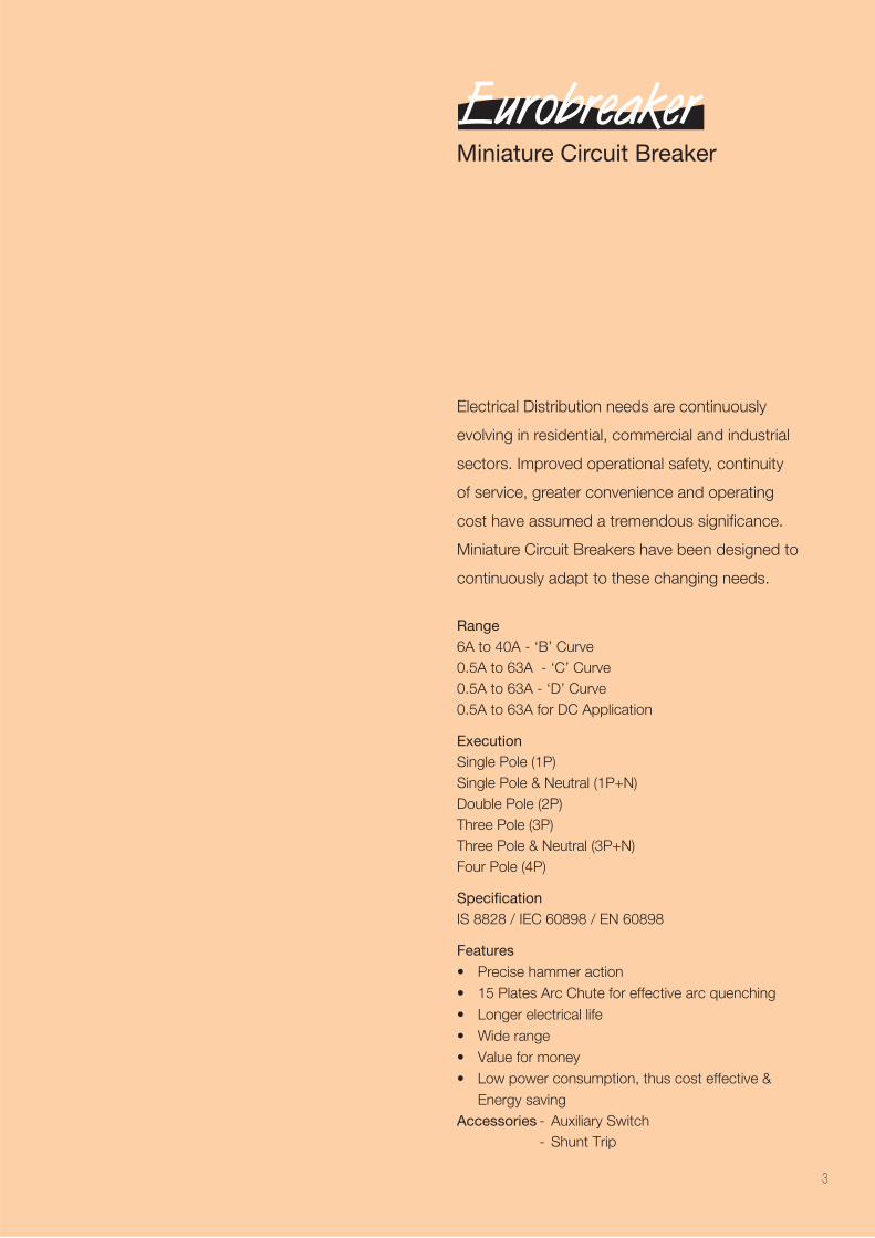
Miniature Circuit Breaker
Electrical Distribution needs are continuously
evolving in residential, commercial and industrial
sectors. Improved operational safety, continuity
of service, greater convenience and operating
cost have assumed a tremendous significance.
Miniature Circuit Breakers have been designed to
continuously adapt to these changing needs.
Range 6A to 40A - ‘B’ Curve0.5A to 63A - ‘C’ Curve0.5A to 63A - ‘D’ Curve0.5A to 63A for DC Application
ExecutionSingle Pole (1P)Single Pole & Neutral (1P+N)Double Pole (2P)Three Pole (3P)Three Pole & Neutral (3P+N)Four Pole (4P)
SpecificationIS 8828 / IEC 60898 / EN 60898
Features
Energy savingAccessories - Auxiliary Switch - Shunt Trip
3
4
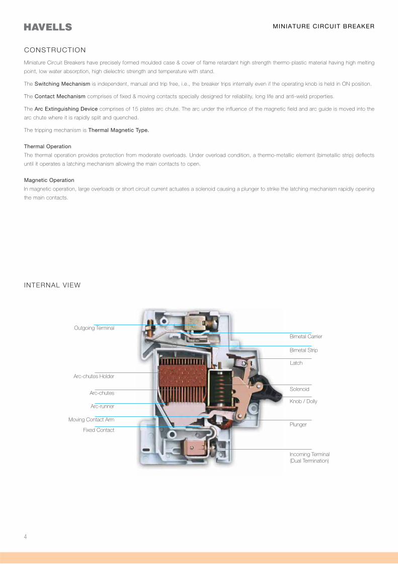
CONSTRUCTION
Miniature Circuit Breakers have precisely formed moulded case & cover of flame retardant high strength thermo-plastic material having high melting
point, low water absorption, high dielectric strength and temperature with stand.
The Switching Mechanism is independent, manual and trip free, i.e., the breaker trips internally even if the operating knob is held in ON position.
The Contact Mechanism comprises of fixed & moving contacts specially designed for reliability, long life and anti-weld properties.
The Arc Extinguishing Device comprises of 15 plates arc chute. The arc under the influence of the magnetic field and arc guide is moved into the
arc chute where it is rapidly split and quenched.
The tripping mechanism is Thermal Magnetic Type.
Thermal Operation
The thermal operation provides protection from moderate overloads. Under overload condition, a thermo-metallic element (bimetallic strip) deflects
until it operates a latching mechanism allowing the main contacts to open.
Magnetic Operation
In magnetic operation, large overloads or short circuit current actuates a solenoid causing a plunger to strike the latching mechanism rapidly opening
the main contacts.
INTERNAL VIEW
Outgoing Terminal
Arc-chutes Holder
Arc-chutes
Arc-runner
Moving Contact Arm
Fixed Contact
Bimetal Carrier
Bimetal Strip
Latch
Solenoid
Knob / Dolly
Plunger
Incoming Terminal(Dual Termination)
MINIATURE CIRCUIT BREAKER
5
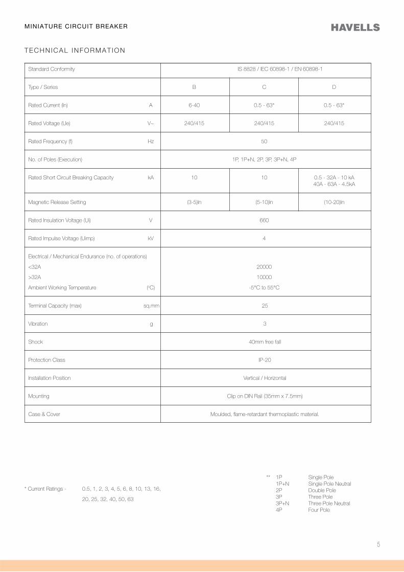
* Current Ratings - 0.5, 1, 2, 3, 4, 5, 6, 8, 10, 13, 16,
20, 25, 32, 40, 50, 63
TECHNICAL INFORMAT ION
Standard Conformity IS 8828 / IEC 60898-1 / EN 60898-1
Type / Series B C D
Rated Current (In) A 6-40 0.5 - 63* 0.5 - 63*
Rated Voltage (Ue) V~ 240/415 240/415 240/415
Rated Frequency (f) Hz 50
No. of Poles (Execution) 1P, 1P+N, 2P, 3P, 3P+N, 4P
Rated Short Circuit Breaking Capacity kA 10 10 0.5 - 32A - 10 kA 40A - 63A - 4.5kA
Magnetic Release Setting (3-5)In (5-10)In (10-20)In
Rated Insulation Voltage (Ui) V 660
Rated Impulse Voltage (Uimp) kV 4
Electrical / Mechanical Endurance (no. of operations)
<32A 20000
>32A 10000
Ambient Working Temperature (oC) -5°C to 55°C
Terminal Capacity (max) sq.mm 25
Vibration g 3
Shock 40mm free fall
Protection Class IP-20
Installation Position Vertical / Horizontal
Mounting Clip on DIN Rail (35mm x 7.5mm)
Case & Cover Moulded, flame-retardant thermoplastic material.
** 1P Single Pole 1P+N Single Pole Neutral 2P Double Pole 3P Three Pole 3P+N Three Pole Neutral 4P Four Pole
MINIATURE CIRCUIT BREAKER
6
MINIATURE CIRCUIT BREAKER
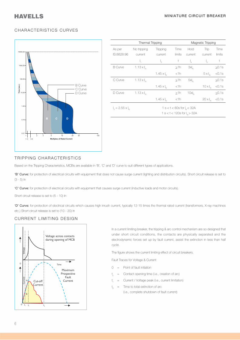
CHARACTERIST ICS CURVES
TR IPP ING CHARACTERIST ICS
Based on the Tripping Characteristics, MCBs are available in ‘B’, ‘C’ and ‘D’ curve to suit different types of applications.
‘B’ Curve: for protection of electrical circuits with equipment that does not cause surge current (lighting and distribution circuits). Short circuit release is set to
(3 - 5) In
‘C’ Curve: for protection of electrical circuits with equipment that causes surge current (inductive loads and motor circuits).
Short circuit release is set to (5 - 10) In
‘D’ Curve: for protection of electrical circuits which causes high inrush current, typically 12-15 times the thermal rated current (transformers, X-ray machines
etc.) Short circuit release is set to (10 - 20) In
CURRENT L IM IT ING DES IGN
In a current limiting breaker, the tripping & arc control mechanism are so designed that
under short circuit conditions, the contacts are physically separated and the
electrodynamic forces set up by fault current, assist the extinction in less than half
cycle.
The figure shows the current limiting effect of circuit breakers.
Fault Traces for Voltage & Current
0 = Point of fault initiation
tx = Contact opening time (i.e., creation of arc)
t1 = Current / Voltage peak (i.e., current limitation)
t2 = Time to total extinction of arc
(i.e., complete shutdown of fault current)
Thermal Tripping Magnetic Tripping
As per No tripping Tripping Time Hold Trip Time
IS:8828:96 current current limits current current limits
I1
I2
t I4
I5
t
B Curve 1.13 x IN
>1h 3xIN >0.1s
1.45 x IN
<1h 5 x IN
<0.1s
C Curve 1.13 x IN
>1h 5xIN >0.1s
1.45 x IN
<1h 10 x IN
<0.1s
D Curve 1.13 x IN
>1h 10xIN >0.1s
1.45 x IN
<1h 20 x IN
<0.1s
l3 = 2.55 x l
N 1 s < t < 60s for l
N < 32A
1 s < t < 120s for lN
> 32A
B CurveC CurveD Curve
7
MINIATURE CIRCUIT BREAKER
Current Limiting design in itself may not fulfill the requirement of quick breaking
(instantaneous action) mainly due to inertia of the Latch mechanism and
interconnected sequence of operations.
A Hammer directly connected to the plunger strikes the moving contact arm
with a force proportional to the peak current there by forcibly separating the
moving contact from the fixed contact much before the latch mechanism
operates. This further reduces the opening time of the circuit breaker.
HAMMER TRIP MECHANISM
AMBIENT TEMPERATURE COMPENSATION / DIVERSITY FACTOR CHART
EFFECT OF FREQUENCY VARIATION
Calculation In / switch = K
1 x K
2 x I
n
Example 4 MCBs with In = 10A, and the amb. temp. is 50oC kept with no gap in between
Solution K1 =0.89 (from graph 1) K2 =0.78 (from graph 2) I
n / pole = 0.89 x 0.78 x 10 = 6.94 A
MCBs are designed to operate at AC frequency 50 / 60 Hz. However, MCBs specially suitable for DC applications and for frequencies upto 400Hz can be
supplied on request.
These can be used on different frequencies in supply from 16 2/ 3 - 60 Hz without any deration.
For higher frequencies, normal MCBs can be used with a multiplication factor which shall only affect its magnetic trip current.
Supply AC DCFrequency 100Hz 200Hz 400Hz
Multiplication Factor 1.1 1.2 1.5 1.5
Maximum Permissible Rated Current(K1 Factor)
Diversity Factor(K2 Factor)
Graph 2
HammerPlunger
K2K
1
Graph 1
8
MINIATURE CIRCUIT BREAKER
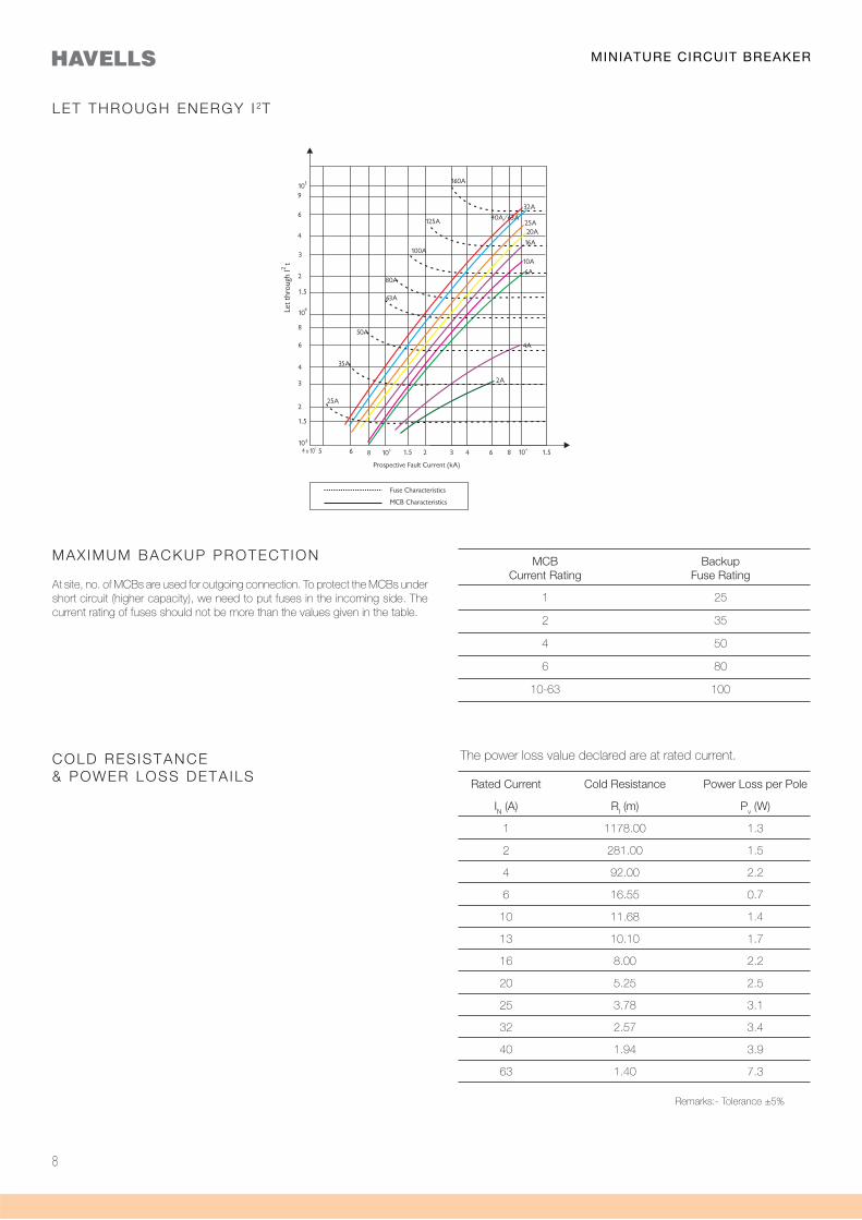
LET THROUGH ENERGY I 2T
MAX IMUM BACKUP PROTECT ION
At site, no. of MCBs are used for outgoing connection. To protect the MCBs under short circuit (higher capacity), we need to put fuses in the incoming side. The current rating of fuses should not be more than the values given in the table.
MCB Backup Current Rating Fuse Rating
1 25
2 35
4 50
6 80
10-63 100
COLD RES ISTANCE& POWER LOSS DETA ILS Rated Current Cold Resistance Power Loss per Pole
IN (A) RI (m) Pv (W)
1 1178.00 1.3
2 281.00 1.5
4 92.00 2.2
6 16.55 0.7
10 11.68 1.4
13 10.10 1.7
16 8.00 2.2
20 5.25 2.5
25 3.78 3.1
32 2.57 3.4
40 1.94 3.9
63 1.40 7.3
The power loss value declared are at rated current.
Remarks:- Tolerance ±5%
9
MINIATURE CIRCUIT BREAKER
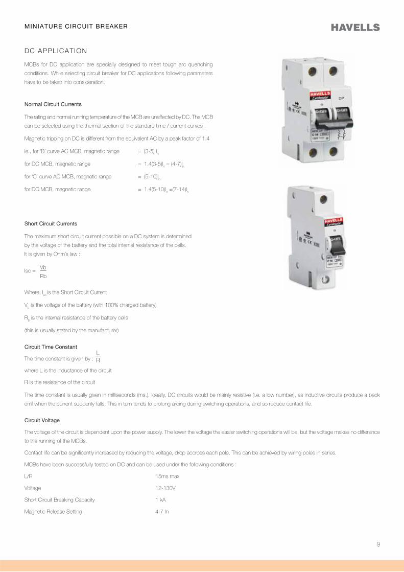
DC APPLICATION
MCBs for DC application are specially designed to meet tough arc quenching
conditions. While selecting circuit breaker for DC applications following parameters
have to be taken into consideration.
Short Circuit Currents
The maximum short circuit current possible on a DC system is determined
by the voltage of the battery and the total internal resistance of the cells.
It is given by Ohm’s law :
Isc = Vb
Rb
Where, Isc
is the Short Circuit Current
Vb is the voltage of the battery (with 100% charged battery)
Rb is the internal resistance of the battery cells
(this is usually stated by the manufacturer)
Circuit Time Constant
The time constant is given by :
where L is the inductance of the circuit
R is the resistance of the circuit
The time constant is usually given in milliseconds (ms.). Ideally, DC circuits would be mainly resistive (i.e. a low number), as inductive circuits produce a back
emf when the current suddenly falls. This in turn tends to prolong arcing during switching operations, and so reduce contact life.
Circuit Voltage
The voltage of the circuit is dependent upon the power supply. The lower the voltage the easier switching operations will be, but the voltage makes no difference
to the running of the MCBs.
Contact life can be significantly increased by reducing the voltage, drop accross each pole. This can be achieved by wiring poles in series.
MCBs have been successfully tested on DC and can be used under the following conditions :
L/R 15ms max
Voltage 12-130V
Short Circuit Breaking Capacity 1 kA
Magnetic Release Setting 4-7 ln
Normal Circuit Currents
The rating and normal running temperature of the MCB are unaffected by DC. The MCB
can be selected using the thermal section of the standard time / current curves .
Magnetic tripping on DC is different from the equivalent AC by a peak factor of 1.4
ie., for ‘B’ curve AC MCB, magnetic range = (3-5) ln
for DC MCB, magnetic range = 1.4(3-5)ln = (4-7)l
n
for ‘C’ curve AC MCB, magnetic range = (5-10)ln
for DC MCB, magnetic range = 1.4(5-10)ln =(7-14)l
n
LR
10
MINIATURE CIRCUIT BREAKER
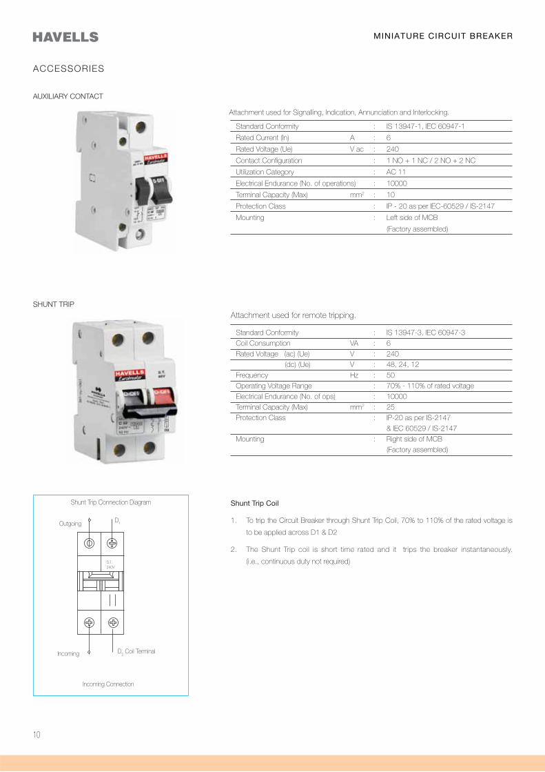
Incoming Connection
Incoming D2 Coil Terminal
ACCESSORIES
AUXILIARY CONTACT
Attachment used for Signalling, Indication, Annunciation and Interlocking.
Standard Conformity : IS 13947-1, IEC 60947-1
Rated Current (In) A : 6
Rated Voltage (Ue) V ac : 240
Contact Configuration : 1 NO + 1 NC / 2 NO + 2 NC
Utilization Category : AC 11
Electrical Endurance (No. of operations) : 10000
Terminal Capacity (Max) mm2 : 10
Protection Class : IP - 20 as per IEC-60529 / IS-2147
Mounting : Left side of MCB
(Factory assembled)
SHUNT TRIP
Standard Conformity : IS 13947-3, IEC 60947-3
Coil Consumption VA : 6
Rated Voltage (ac) (Ue) V : 240
(dc) (Ue) V : 48, 24, 12
Frequency Hz : 50
Operating Voltage Range : 70% - 110% of rated voltage
Electrical Endurance (No. of ops) : 10000
Terminal Capacity (Max) mm2 : 25
Protection Class : IP-20 as per IS-2147
& IEC 60529 / IS-2147
Mounting : Right side of MCB
(Factory assembled)
Attachment used for remote tripping.
Shunt Trip Coil
1. To trip the Circuit Breaker through Shunt Trip Coil, 70% to 110% of the rated voltage is
to be applied across D1 & D2
2. The Shunt Trip coil is short time rated and it trips the breaker instantaneously.
(i.e., continuous duty not required)
Shunt Trip Connection Diagram
Outgoing
S.T.240V
D1
11
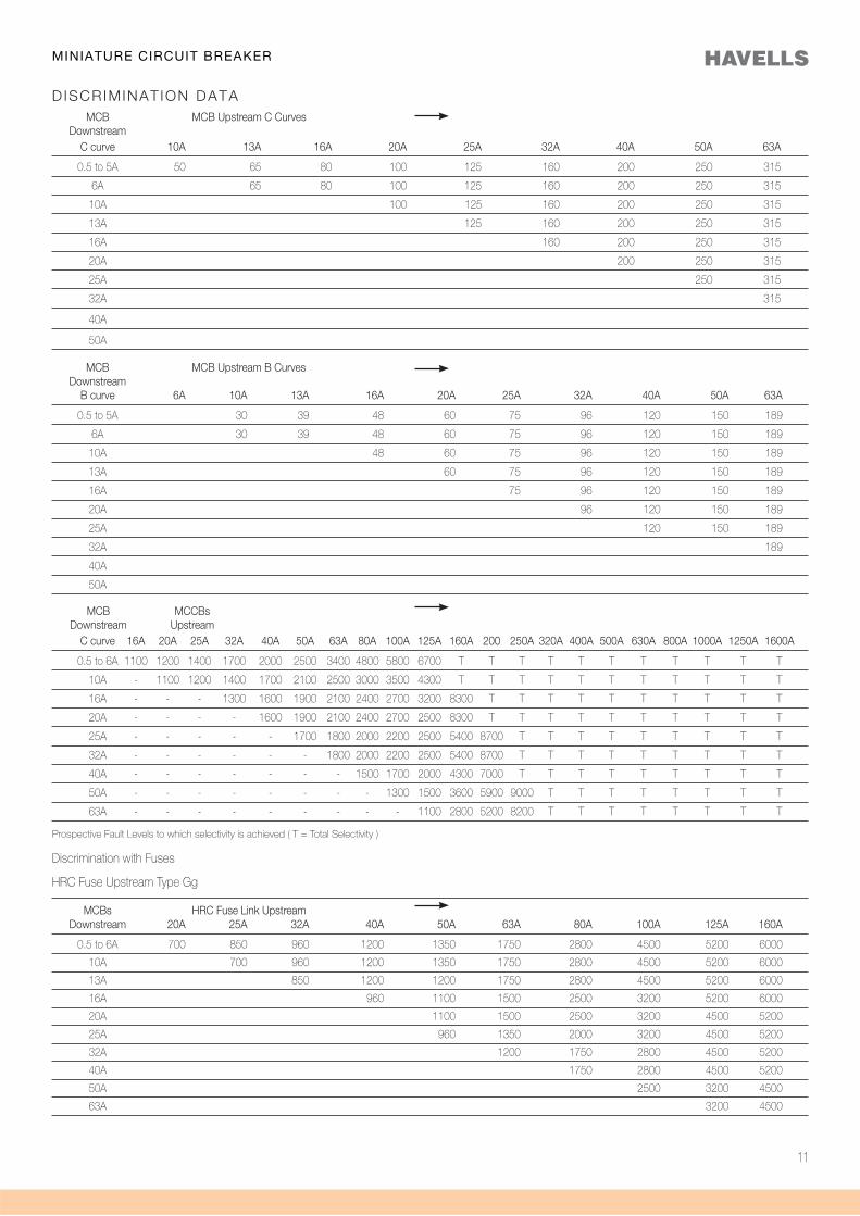
MCB MCB Upstream C Curves Downstream C curve 10A 13A 16A 20A 25A 32A 40A 50A 63A
0.5 to 5A 50 65 80 100 125 160 200 250 315
6A 65 80 100 125 160 200 250 315
10A 100 125 160 200 250 315
13A 125 160 200 250 315
16A 160 200 250 315
20A 200 250 315
25A 250 315
32A 315
40A
50A
MCB MCB Upstream B Curves Downstream B curve 6A 10A 13A 16A 20A 25A 32A 40A 50A 63A
0.5 to 5A 30 39 48 60 75 96 120 150 189
6A 30 39 48 60 75 96 120 150 189
10A 48 60 75 96 120 150 189
13A 60 75 96 120 150 189
16A 75 96 120 150 189
20A 96 120 150 189
25A 120 150 189
32A 189
40A
50A
Discrimination with Fuses
HRC Fuse Upstream Type Gg
MCBs HRC Fuse Link Upstream Downstream 20A 25A 32A 40A 50A 63A 80A 100A 125A 160A
0.5 to 6A 700 850 960 1200 1350 1750 2800 4500 5200 6000
10A 700 960 1200 1350 1750 2800 4500 5200 6000
13A 850 1200 1200 1750 2800 4500 5200 6000
16A 960 1100 1500 2500 3200 5200 6000
20A 1100 1500 2500 3200 4500 5200
25A 960 1350 2000 3200 4500 5200
32A 1200 1750 2800 4500 5200
40A 1750 2800 4500 5200
50A 2500 3200 4500
63A 3200 4500
MCB MCCBs Downstream Upstream C curve 16A 20A 25A 32A 40A 50A 63A 80A 100A 125A 160A 200 250A 320A 400A 500A 630A 800A 1000A 1250A 1600A
0.5 to 6A 1100 1200 1400 1700 2000 2500 3400 4800 5800 6700 T T T T T T T T T T T
10A - 1100 1200 1400 1700 2100 2500 3000 3500 4300 T T T T T T T T T T T
16A - - - 1300 1600 1900 2100 2400 2700 3200 8300 T T T T T T T T T T
20A - - - - 1600 1900 2100 2400 2700 2500 8300 T T T T T T T T T T
25A - - - - - 1700 1800 2000 2200 2500 5400 8700 T T T T T T T T T
32A - - - - - - 1800 2000 2200 2500 5400 8700 T T T T T T T T T
40A - - - - - - - 1500 1700 2000 4300 7000 T T T T T T T T T
50A - - - - - - - - 1300 1500 3600 5900 9000 T T T T T T T T
63A - - - - - - - - - 1100 2800 5200 8200 T T T T T T T T
Prospective Fault Levels to which selectivity is achieved ( T = Total Selectivity )
DISCRIMINAT ION DATA
MINIATURE CIRCUIT BREAKER
12
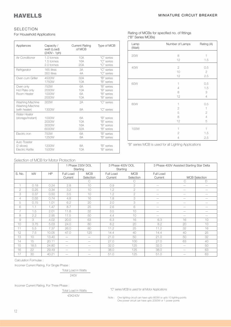
Selection of MCB for Motor Protection 1 Phase 230V DOL 3 Phase 400V DOL 3 Phase 400V Assisted Starting Star Delta Starting Starting S. No. kW HP Full Load MCB Full Load MCB Full Load Current Selection Current Selection Current MCB Selection C C C D 1 0.18 0.24 2.8 10 0.9 2 — — — 2 0.25 0.34 3.2 10 1.2 2 — — — 3 0.37 0.50 3.5 10 1.2 2 — — — 4 0.55 0.74 4.8 16 1.8 3 — — — 5 0.75 1.01 6.2 20 2.0 3 — — — 6 1.1 1.47 8.7 25 2.6 6 — — — 7 1.5 2.01 11.8 32 3.5 10 — — — 8 2.2 2.95 17.5 50 4.4 10 — — — 9 3 4.02 20.0 63 6.3 16 6.3 16 10 10 3.75 5.03 24.0 80 8.2 20 8.2 20 10 11 5.5 7.37 26.0 80 11.2 25 11.2 32 16 12 7.5 10.05 47.0 125 14.4 40 14.4 40 25 13 10 13.40 — — 21.0 50 21.0 50 32 14 15 20.11 — — 27.0 100 27.0 63 40 15 18.5 24.80 — — 32.0 125 32.0 — 50 16 22 29.49 — — 38.0 125 38.0 — 63 17 30 40.21 — — 51.0 125 51.0 — 63
SELECTION CHART
Appliances Capacity / Current Rating Type of MCB watt (Load) of MCB (240V~ 1ph)
Air Conditioner 1.0 tonnes 10A “C” series 1.5 tonnes 16A “C” series 2.0 tonnes 20A “C” series
Refrigerator 165 litres 3A “C” series 350 litres 4A “C” series
Oven cum Griller 4500W 32A “B” series 1750W 10A “B” series
Oven only 750W 6A “B” seriesHot Plate only 2000W 10A “B” seriesRoom Heater 1000W 6A “B” series 2000W 10A “B” series
Washing Machine 300W 2A “C” seriesWashing Machine (with heater) 1300W 8A “C” series
Water Heater(storage/instant) 1000W 6A “B” series 2000W 10A “B” series 3000W 16A “B” series 6000W 32A “B” series
Electric iron 750W 6A “B” series 1250W 8A “B” series
Auto Toaster(2 slices) 1200W 8A “B” seriesElectric Kettle 1500W 10A “B” series
For Household Applications
Lamp Number of Lamps Rating (A) (Watt)
20W 8 1 12 1.5
40W 2 0.5 10 2 12 2.5
60W 1 0.5 4 1.5 8 3 12 4
80W 1 0.5 2 1 5 2 8 4 12 5
100W 1 1 2 1.5
4 2.5
Rating of MCBs for specified no. of fittings (“B” Series MCBs)
“B” series MCB is used for all Lighting Applications
“C” series MCB is used for all Motor Applications
Note : One lighting circuit can have upto 800W or upto 10 lighting points One power circuit can have upto 2000W or 1 power points
Calculation Formulae :
Incomer Current Rating, For Single Phase :
Total Load in Watts
240V
Incomer Current Rating, For Three Phase :
Total Load in Watts
√3X240V
MINIATURE CIRCUIT BREAKER
13
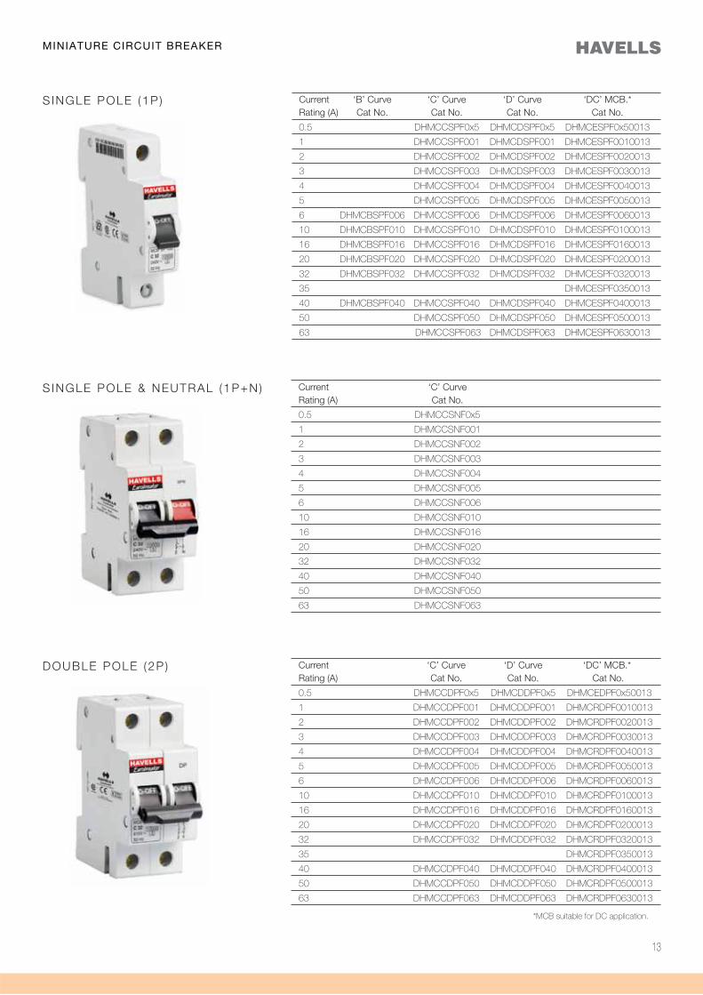
Current ‘C’ Curve Rating (A) Cat No.
0.5 DHMCCSNF0x5
1 DHMCCSNF001
2 DHMCCSNF002
3 DHMCCSNF003
4 DHMCCSNF004
5 DHMCCSNF005
6 DHMCCSNF006
10 DHMCCSNF010
16 DHMCCSNF016
20 DHMCCSNF020
32 DHMCCSNF032
40 DHMCCSNF040
50 DHMCCSNF050
63 DHMCCSNF063
S INGLE POLE & NEUTRAL (1P+N)
DOUBLE POLE (2P ) Current ‘C’ Curve ‘D’ Curve ‘DC’ MCB.* Rating (A) Cat No. Cat No. Cat No.
0.5 DHMCCDPF0x5 DHMCDDPF0x5 DHMCEDPF0x50013
1 DHMCCDPF001 DHMCDDPF001 DHMCRDPF0010013
2 DHMCCDPF002 DHMCDDPF002 DHMCRDPF0020013
3 DHMCCDPF003 DHMCDDPF003 DHMCRDPF0030013
4 DHMCCDPF004 DHMCDDPF004 DHMCRDPF0040013
5 DHMCCDPF005 DHMCDDPF005 DHMCRDPF0050013
6 DHMCCDPF006 DHMCDDPF006 DHMCRDPF0060013
10 DHMCCDPF010 DHMCDDPF010 DHMCRDPF0100013
16 DHMCCDPF016 DHMCDDPF016 DHMCRDPF0160013
20 DHMCCDPF020 DHMCDDPF020 DHMCRDPF0200013
32 DHMCCDPF032 DHMCDDPF032 DHMCRDPF0320013
35 DHMCRDPF0350013
40 DHMCCDPF040 DHMCDDPF040 DHMCRDPF0400013
50 DHMCCDPF050 DHMCDDPF050 DHMCRDPF0500013
63 DHMCCDPF063 DHMCDDPF063 DHMCRDPF0630013
*MCB suitable for DC application.
Current ‘B’ Curve ‘C’ Curve ‘D’ Curve ‘DC’ MCB.* Rating (A) Cat No. Cat No. Cat No. Cat No.
0.5 DHMCCSPF0x5 DHMCDSPF0x5 DHMCESPF0x50013
1 DHMCCSPF001 DHMCDSPF001 DHMCESPF0010013
2 DHMCCSPF002 DHMCDSPF002 DHMCESPF0020013
3 DHMCCSPF003 DHMCDSPF003 DHMCESPF0030013
4 DHMCCSPF004 DHMCDSPF004 DHMCESPF0040013
5 DHMCCSPF005 DHMCDSPF005 DHMCESPF0050013
6 DHMCBSPF006 DHMCCSPF006 DHMCDSPF006 DHMCESPF0060013
10 DHMCBSPF010 DHMCCSPF010 DHMCDSPF010 DHMCESPF0100013
16 DHMCBSPF016 DHMCCSPF016 DHMCDSPF016 DHMCESPF0160013
20 DHMCBSPF020 DHMCCSPF020 DHMCDSPF020 DHMCESPF0200013
32 DHMCBSPF032 DHMCCSPF032 DHMCDSPF032 DHMCESPF0320013
35 DHMCESPF0350013
40 DHMCBSPF040 DHMCCSPF040 DHMCDSPF040 DHMCESPF0400013
50 DHMCCSPF050 DHMCDSPF050 DHMCESPF0500013
63 DHMCCSPF063 DHMCDSPF063 DHMCESPF0630013
S INGLE POLE (1P )
MINIATURE CIRCUIT BREAKER
14
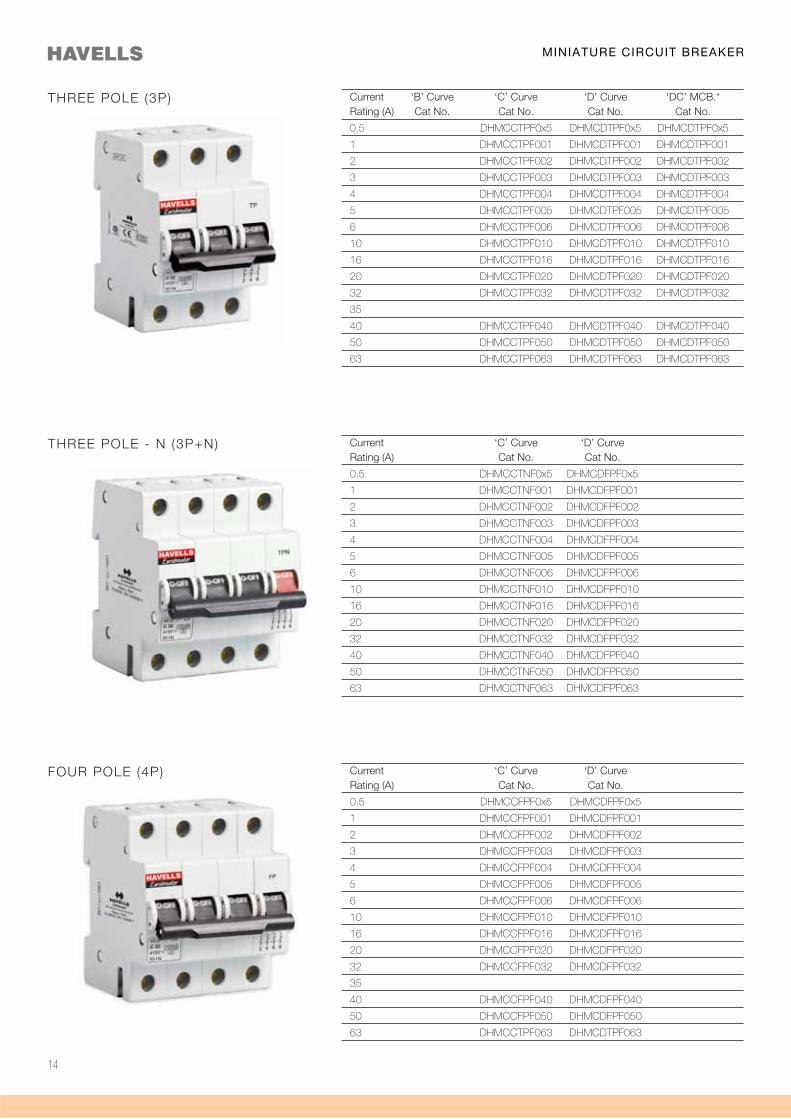
Current ‘B’ Curve ‘C’ Curve ‘D’ Curve ‘DC’ MCB.* Rating (A) Cat No. Cat No. Cat No. Cat No.
0.5 DHMCCTPF0x5 DHMCDTPF0x5 DHMCDTPF0x5
1 DHMCCTPF001 DHMCDTPF001 DHMCDTPF001
2 DHMCCTPF002 DHMCDTPF002 DHMCDTPF002
3 DHMCCTPF003 DHMCDTPF003 DHMCDTPF003
4 DHMCCTPF004 DHMCDTPF004 DHMCDTPF004
5 DHMCCTPF005 DHMCDTPF005 DHMCDTPF005
6 DHMCCTPF006 DHMCDTPF006 DHMCDTPF006
10 DHMCCTPF010 DHMCDTPF010 DHMCDTPF010
16 DHMCCTPF016 DHMCDTPF016 DHMCDTPF016
20 DHMCCTPF020 DHMCDTPF020 DHMCDTPF020
32 DHMCCTPF032 DHMCDTPF032 DHMCDTPF032
35
40 DHMCCTPF040 DHMCDTPF040 DHMCDTPF040
50 DHMCCTPF050 DHMCDTPF050 DHMCDTPF050
63 DHMCCTPF063 DHMCDTPF063 DHMCDTPF063
THREE POLE (3P)
THREE POLE - N (3P+N) Current ‘C’ Curve ‘D’ Curve Rating (A) Cat No. Cat No.
0.5 DHMCCTNF0x5 DHMCDFPF0x5
1 DHMCCTNF001 DHMCDFPF001
2 DHMCCTNF002 DHMCDFPF002
3 DHMCCTNF003 DHMCDFPF003
4 DHMCCTNF004 DHMCDFPF004
5 DHMCCTNF005 DHMCDFPF005
6 DHMCCTNF006 DHMCDFPF006
10 DHMCCTNF010 DHMCDFPF010
16 DHMCCTNF016 DHMCDFPF016
20 DHMCCTNF020 DHMCDFPF020
32 DHMCCTNF032 DHMCDFPF032
40 DHMCCTNF040 DHMCDFPF040
50 DHMCCTNF050 DHMCDFPF050
63 DHMCCTNF063 DHMCDFPF063
FOUR POLE (4P) Current ‘C’ Curve ‘D’ Curve Rating (A) Cat No. Cat No.
0.5 DHMCCFPF0x5 DHMCDFPF0x5
1 DHMCCFPF001 DHMCDFPF001
2 DHMCCFPF002 DHMCDFPF002
3 DHMCCFPF003 DHMCDFPF003
4 DHMCCFPF004 DHMCDFPF004
5 DHMCCFPF005 DHMCDFPF005
6 DHMCCFPF006 DHMCDFPF006
10 DHMCCFPF010 DHMCDFPF010
16 DHMCCFPF016 DHMCDFPF016
20 DHMCCFPF020 DHMCDFPF020
32 DHMCCFPF032 DHMCDFPF032
35
40 DHMCCFPF040 DHMCDFPF040
50 DHMCCFPF050 DHMCDFPF050
63 DHMCCTPF063 DHMCDTPF063
MINIATURE CIRCUIT BREAKER
15
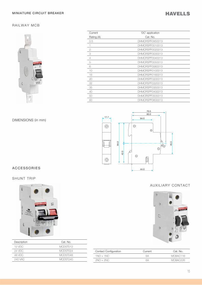
ACCESSORIES
Description Cat. No.
12 VDC MCDST012
24 VDC MCDST024
48 VDC MCDST048
240 VAC MCDST240
SHUNT TR IP
Contact Configuration Current Cat. No.
1NO + 1NC 6A MCBAC116
2NO + 2NC 6A MCBAC226
AUX IL IARY CONTACT
RAILWAY MCB
Current ‘DC’ application
Rating (A) Cat. No.
0.5 DHMCRSPF0X50013
1 DHMCRSPF0010013
2 DHMCRSPF0020013
3 DHMCRSPF0030013
4 DHMCRSPF0040013
5 DHMCRSPF0050013
6 DHMCRSPF0060013
10 DHMCRSPF0100013
16 DHMCRSPF0160013
20 DHMCRSPF0200013
32 DHMCRSPF0320013
35 DHMCRSPF0350013
40 DHMCRSPF0400013
50 DHMCRSPF0500013
60 DHMCRSPF0600013
MINIATURE CIRCUIT BREAKER
DIMENSIONS (in mm)
16
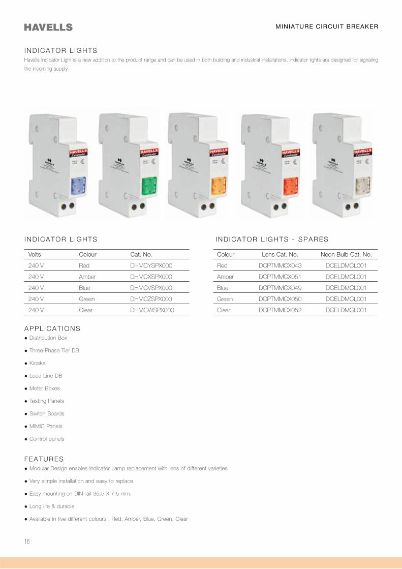
Volts Colour Cat. No.
240 V Red DHMCYSPX000
240 V Amber DHMCXSPX000
240 V Blue DHMCVSPX000
240 V Green DHMCZSPX000
240 V Clear DHMCWSPX000
IND ICATOR L IGHTSHavells Indicator Light is a new addition to the product range and can be used in both building and industrial installations. Indicator lights are designed for signaling
the incoming supply.
Colour Lens Cat. No. Neon Bulb Cat. No.
Red DCPTMMCX043 DCELDMCL001
Amber DCPTMMCX051 DCELDMCL001
Blue DCPTMMCX049 DCELDMCL001
Green DCPTMMCX050 DCELDMCL001
Clear DCPTMMCX052 DCELDMCL001
APPL ICAT IONS Distribution Box
Three Phase Tier DB
Kiosks
Load Line DB
Meter Boxes
Testing Panels
Switch Boards
MIMIC Panels
Control panels
FEATURES Modular Design enables Indicator Lamp replacement with lens of different varieties
Very simple installation and easy to replace
Easy mounting on DIN rail 35.5 X 7.5 mm.
Long life & durable
Available in five different colours : Red, Amber, Blue, Green, Clear
IND ICATOR L IGHTS - SPARESIND ICATOR L IGHTS
MINIATURE CIRCUIT BREAKER
17
Specification IS 13947 (Part 5)
IEC 60947-5-1
Contacts Rated Operation Voltage 240 V ac
Rating Electrical Power 1.2 Watt
Frequency 50 Hz
Type of Lamp Socket E - 10 Thread
Terminal Capacity 10 mm2
Light Indication Colour
Light Permanent
Source Neon Lamp
Other Data Mounting on DIN Rail 35 mm x 7.5 mm
Degree of Protection IP 20
Ambient Temperature -5 to 55° C
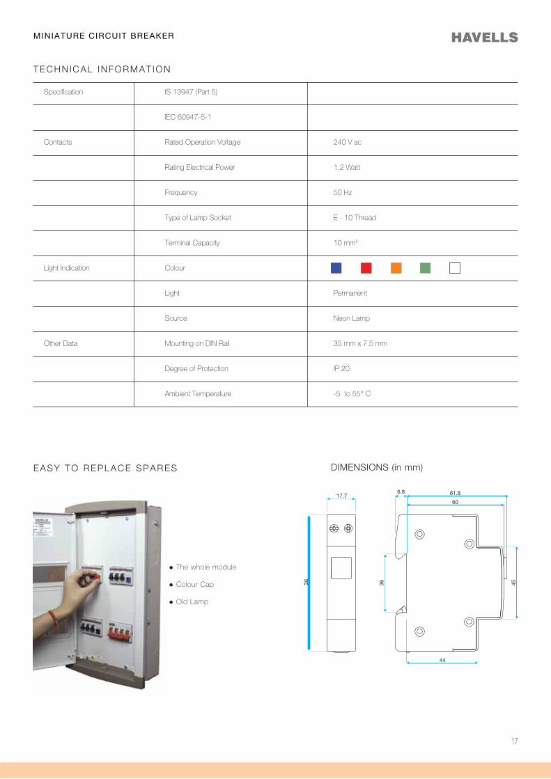
TECHNICAL INFORMAT ION
The whole module
Colour Cap
Old Lamp
EASY TO REPLACE SPARES
MINIATURE CIRCUIT BREAKER
DIMENSIONS (in mm)

18
Miniature Circuit Breaker(80 - 125)
Electrical Distribution needs are continuously
evolving in residential, commercial and industrial
sectors. Improved operational safety, continuity
of service, greater convenience and operating
cost have assumed a tremendous significance.
Miniature Circuit Breakers have been designed to
continuously adopt to these changing needs.
Range 80A to 125A - ‘C’ Curve
ExecutionSingle Pole (1P)Three Pole (3P)Three Pole & Neutral (3P+N)
SpecificationIS 8828-1996 / IEC 60898 - 2002
Features
rated current In of the device In (A) Colour 80 (Silver) 100 (Red) 125 (Yellow)
status of the device Indicator colour device status (Red) ON (Green) OFF
function
19
20
Standard Conformity IS 8828 / IEC 60898-1
Type/Series C
Rated Current (In) A 80A - 125A*
Rated Voltage (ac) (Ue) V 240/415
Rated Frequency (f) Hz 50-60 Hz
Nos. of Poles (Execution) 1P, 3P, 3P+N**
Rated Short Circuit Breaking Capacity kA 10
Magnetic Release Setting (5-10)In
Rated Insulation Voltage (Ui) kV 4
Electrical Endurance (No. of operations) 10000 10000
Ambient Working Temperature (oC) **-5°C to + 55°C
Terminal Capacity (Max) mm2 50
Tightening Torque Nm 3.5
Vibration g 3
Shock 40mm fall
Protection Class IP-20
Installation Position Vertical / Horizontal
Mounting Clip on DIN Rail (35mm x 7.5mm)
Case & Cover Moulded, flame retardant thermoplastic material.
TECHNICAL INFORMATION
* Current Ratings - 80A, 100A, 125A
# ‘D’ Curve MCBs are available on request
** 1P Single Pole
3P Three Pole
3P+N Three Pole Neutral
MINIATURE CIRCUIT BREAKER(80-125A MCB)
21
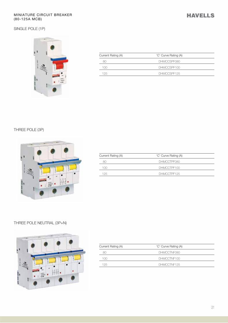
SINGLE POLE (1P)
Current Rating (A) ‘C’ Curve Rating (A)
80 DHMCCSPF080
100 DHMCCSPF100
125 DHMCCSPF125
THREE POLE (3P)
THREE POLE NEUTRAL (3P+N)
Current Rating (A) ‘C’ Curve Rating (A)
80 DHMCCTPF080
100 DHMCCTPF100
125 DHMCCTPF125
Current Rating (A) ‘C’ Curve Rating (A)
80 DHMCCTNF080
100 DHMCCTNF100
125 DHMCCTNF125
MINIATURE CIRCUIT BREAKER(80-125A MCB)
22
TECHNICAL INFORMATION
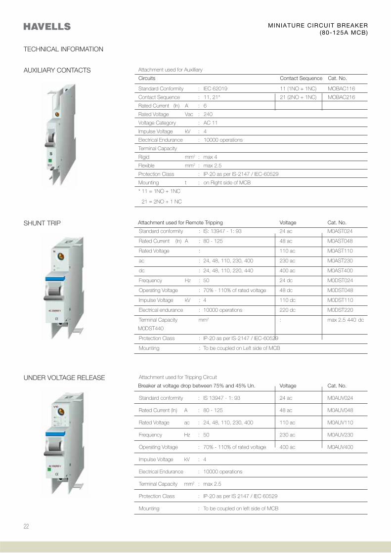
AUXILIARY CONTACTS Attachment used for Auxilliary
Circuits Contact Sequence Cat. No.
Standard Conformity : IEC 62019 11 (1NO + 1NC) MOBAC116
Contact Sequence : 11, 21* 21 (2NO + 1NC) MOBAC216
Rated Current (ln) A : 6
Rated Voltage Vac : 240
Voltage Category : AC 11
Impulse Voltage kV : 4
Electrical Endurance : 10000 operations
Terminal Capacity
Rigid mm2 : max 4
Flexible mm2 : max 2.5
Protection Class : IP-20 as per IS-2147 / IEC-60529
Mounting t : on Right side of MCB
* 11 = 1NO + 1NC
21 = 2NO + 1 NC
Attachment used for Remote Tripping Voltage Cat. No.
Standard conformity : IS: 13947 - 1: 93 24 ac M0AST024
Rated Current (ln) A : 80 - 125 48 ac M0AST048
Rated Voltage : 110 ac M0AST110
ac : 24, 48, 110, 230, 400 230 ac M0AST230
dc : 24, 48, 110, 220, 440 400 ac M0AST400
Frequency Hz : 50 24 dc M0DST024
Operating Voltage : 70% - 110% of rated voltage 48 dc M0DST048
Impulse Voltage kV : 4 110 dc M0DST110
Electrical endurance : 10000 operations 220 dc M0DST220
Terminal Capacity mm2 : max 2.5 440 dc
M0DST440
Protection Class : IP-20 as per IS-2147 / IEC-60529
Mounting : To be coupled on Left side of MCB
SHUNT TRIP
UNDER VOLTAGE RELEASE Attachment used for Tripping Circuit
Breaker at voltage drop between 75% and 45% Un. Voltage Cat. No.
Standard conformity : IS 13947 - 1: 93 24 ac M0AUV024
Rated Current (ln) A : 80 - 125 48 ac M0AUV048
Rated Voltage ac : 24, 48, 110, 230, 400 110 ac M0AUV110
Frequency Hz : 50 230 ac M0AUV230
Operating Voltage : 70% - 110% of rated voltage 400 ac M0AUV400
Impulse Voltage kV : 4
Electrical Endurance : 10000 operations
Terminal Capacity mm2 : max 2.5
Protection Class : IP-20 as per IS 2147 / IEC 60529
Mounting : To be coupled on left side of MCB
MINIATURE CIRCUIT BREAKER(80-125A MCB)
23
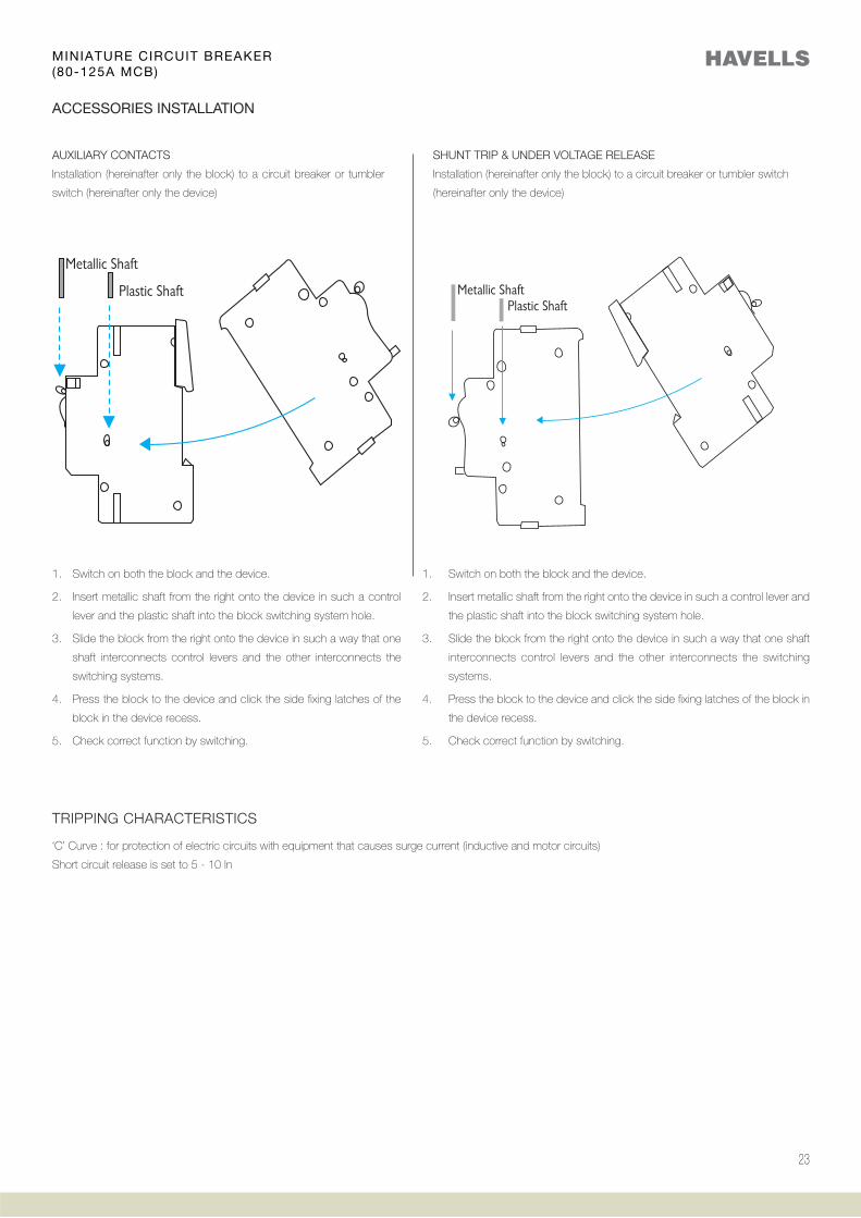
SHUNT TRIP & UNDER VOLTAGE RELEASE
Installation (hereinafter only the block) to a circuit breaker or tumbler switch
(hereinafter only the device)
1. Switch on both the block and the device.
2. Insert metallic shaft from the right onto the device in such a control
lever and the plastic shaft into the block switching system hole.
3. Slide the block from the right onto the device in such a way that one
shaft interconnects control levers and the other interconnects the
switching systems.
4. Press the block to the device and click the side fixing latches of the
block in the device recess.
5. Check correct function by switching.
AUXILIARY CONTACTS
Installation (hereinafter only the block) to a circuit breaker or tumbler
switch (hereinafter only the device)
1. Switch on both the block and the device.
2. Insert metallic shaft from the right onto the device in such a control lever and
the plastic shaft into the block switching system hole.
3. Slide the block from the right onto the device in such a way that one shaft
interconnects control levers and the other interconnects the switching
systems.
4. Press the block to the device and click the side fixing latches of the block in
the device recess.
5. Check correct function by switching.
ACCESSORIES INSTALLATION
TRIPPING CHARACTERISTICS
‘C’ Curve : for protection of electric circuits with equipment that causes surge current (inductive and motor circuits)
Short circuit release is set to 5 - 10 ln
MINIATURE CIRCUIT BREAKER(80-125A MCB)

24
Mini MCB
Havells Mini MCB is a single composite device,
which provides, protection against overload
and short circuit faults. It is designed with
unique mounting concept, for use in domestic
& commercial distribution systems, at the most
downstream circuit (switchboards / DESB),
ensuring even higher degree of protection for
discriminating applications.
In normal operation, this new Mini MCB is safe to
use & there is no threat to user and environment.
Range 6A, 10A, 16A, 20A, 25A, 32A
ExecutionSingle Pole (1P)
SpecificationIS 8828-1996
Features
board itself
25
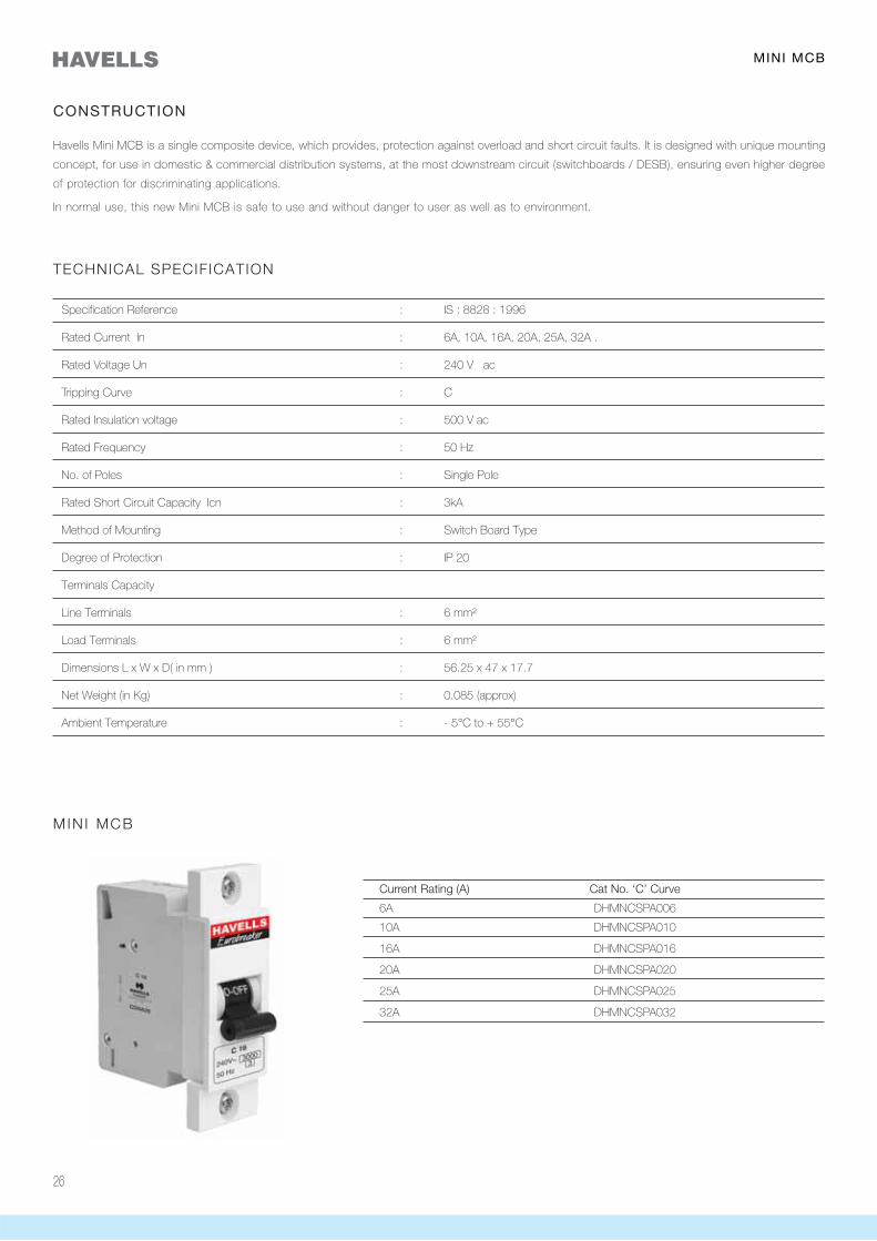
26
Specification Reference : IS : 8828 : 1996
Rated Current In : 6A, 10A, 16A, 20A, 25A, 32A .
Rated Voltage Un : 240 V ac
Tripping Curve : C
Rated Insulation voltage : 500 V ac
Rated Frequency : 50 Hz
No. of Poles : Single Pole
Rated Short Circuit Capacity Icn : 3kA
Method of Mounting : Switch Board Type
Degree of Protection : IP 20
Terminals Capacity
Line Terminals : 6 mm²
Load Terminals : 6 mm²
Dimensions L x W x D( in mm ) : 56.25 x 47 x 17.7
Net Weight (in Kg) : 0.085 (approx)
Ambient Temperature : - 5°C to + 55°C
CONSTRUCTION
Havells Mini MCB is a single composite device, which provides, protection against overload and short circuit faults. It is designed with unique mounting
concept, for use in domestic & commercial distribution systems, at the most downstream circuit (switchboards / DESB), ensuring even higher degree
of protection for discriminating applications.
In normal use, this new Mini MCB is safe to use and without danger to user as well as to environment.
TECHNICAL SPECIFICATION
Current Rating (A) Cat No. ‘C’ Curve
6A DHMNCSPA006
10A DHMNCSPA010
16A DHMNCSPA016
20A DHMNCSPA020
25A DHMNCSPA025
32A DHMNCSPA032
MIN I MCB
MINI MCB
27
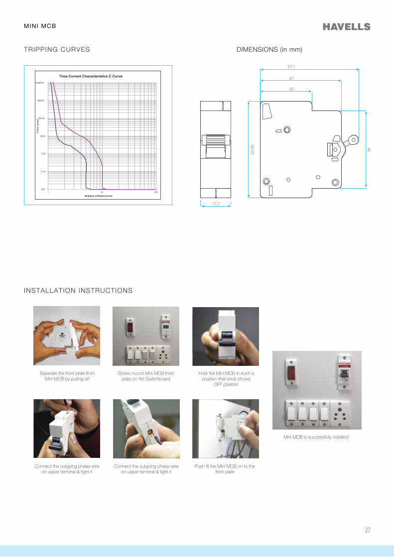
TRIPPING CURVES
INSTALLATION INSTRUCTIONS
MINI MCB
DIMENSIONS (in mm)
Seperate the front plate from Mini MCB by pulling off
Connect the outgoing phase wire on upper terminal & tight it
Connect the outgoing phase wire on upper terminal & tight it
Push fit the Mini MCB on to the front plate
Mini MCB is successfully installed
Screw mount Mini MCB frontplate on the Switchboard
Hold the Mini MCB in such a position that knob shows
OFF position

28

Isolator
They are switch disconnectors with independent
manual operation, capable of making, carrying
and breaking currents under normal circuit
conditions, which may include operating
overload condition and also carry currents under
specified abnormal circuit conditions such as
those of short circuit for a specified time
Range 40A - 63A, 80A - 125A
ExecutionSingle Pole (1P)Double Pole (2P)Three Pole (3P)Four Pole (4P)
SpecificationIS 13947-3 / IEC 60947 - 3
Features
energy saving
29
30
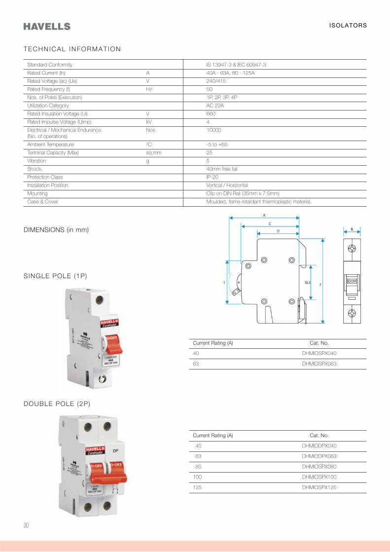
Current Rating (A) Cat. No.
40 DHMIOSPX040
63 DHMIOSPX063
Current Rating (A) Cat. No.
40 DHMIODPX040
63 DHMIODPX063
80 DHMIOSPX080
100 DHMIOSPX100
125 DHMIOSPX125
DOUBLE POLE (2P)
TECHNICAL INFORMAT ION
Standard Conformity IS 13947-3 & IEC 60947-3
Rated Current (In) A 40A - 63A, 80 - 125A
Rated Voltage (ac) (Ue) V 240/415
Rated Frequency (f) Hz 50
Nos. of Poles (Execution) 1P, 2P, 3P, 4P
Utilization Category AC 22A
Rated Insulation Voltage (Ui) V 660
Rated Impulse Voltage (Uimp) kV 4
Electrical / Mechanical Endurance Nos 10000(No. of operations)
Ambient Temperature 0C -5 to +55
Terminal Capacity (Max) sq.mm 25
Vibration g 5
Shock 40mm free fall
Protection Class IP-20
Installation Position Vertical / Horizontal
Mounting Clip on DIN Rail (35mm x 7.5mm)
Case & Cover Moulded, flame retardant thermoplastic material.
SINGLE POLE (1P)
ISOLATORS
DIMENSIONS (in mm)
31
ISOLATORS
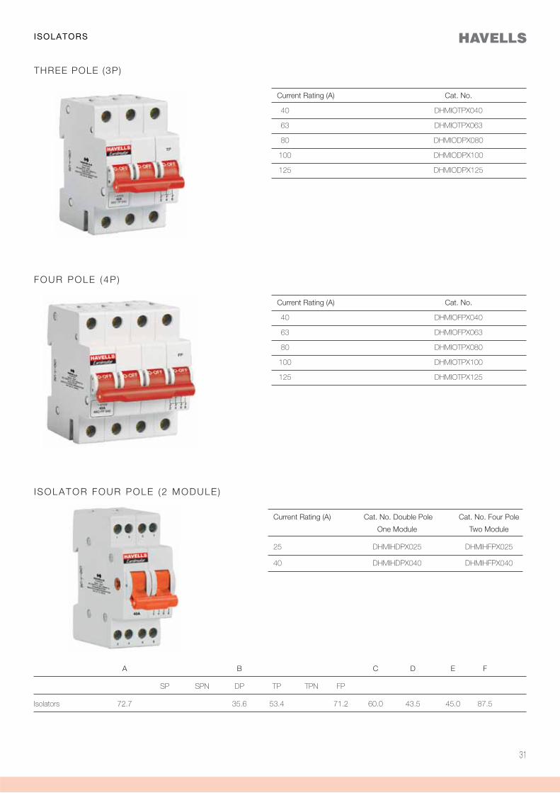
THREE POLE (3P)
Current Rating (A) Cat. No.
40 DHMIOTPX040
63 DHMIOTPX063
80 DHMIODPX080
100 DHMIODPX100
125 DHMIODPX125
FOUR POLE (4P )
Current Rating (A) Cat. No.
40 DHMIOFPX040
63 DHMIOFPX063
80 DHMIOTPX080
100 DHMIOTPX100
125 DHMIOTPX125
I SOLATOR FOUR POLE (2 MODULE )
Current Rating (A) Cat. No. Double Pole Cat. No. Four Pole
One Module Two Module
25 DHMIHDPX025 DHMIHFPX025
40 DHMIHDPX040 DHMIHFPX040
A B C D E F
SP SPN DP TP TPN FP
Isolators 72.7 35.6 53.4 71.2 60.0 43.5 45.0 87.5

32
Changeover Switch
MCB Changeover switch finds wide & varied
applications in industries as well as in domestic
sphere for use in low voltage distribution circuits,
wherever continuity of supply is necessary, for
switching to an alternate source of supply from
main supply and vice - versa.
They are switch disconnectors with independent
manual operation, capable of making, carrying
and breaking currents under normal circuit
conditions, which may include operating
overload condition and also carry currents under
specified abnormal circuit conditions such as
those of short circuit for a specified time.
Range 25A & 40A
ExecutionDouble Pole (2P)Four Pole (4P)
SpecificationIS 13947-3 / IEC 60947 - 3
Features
ELCB, Isolator in Distribution Board
33
34
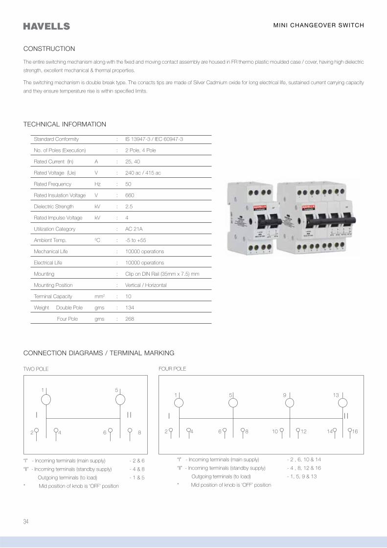
CONSTRUCTION
The entire switching mechanism along with the fixed and moving contact assembly are housed in FR thermo plastic moulded case / cover, having high dielectric
strength, excellent mechanical & thermal properties.
The switching mechanism is double break type. The conacts tips are made of Silver Cadmium oxide for long electrical life, sustained current carrying capacity
and they ensure temperature rise is within specified limits.
TECHNICAL INFORMATION
Standard Conformity : IS 13947-3 / IEC 60947-3
No. of Poles (Execution) : 2 Pole, 4 Pole
Rated Current (In) A : 25, 40
Rated Voltage (Ue) V : 240 ac / 415 ac
Rated Frequency Hz : 50
Rated Insulation Voltage V : 660
Dielectric Strength kV : 2.5
Rated Impulse Voltage kV : 4
Utilization Category : AC 21A
Ambient Temp. 0C : -5 to +55
Mechanical Life : 10000 operations
Electrical Life : 10000 operations
Mounting : Clip on DIN Rail (35mm x 7.5) mm
Mounting Position : Vertical / Horizontal
Terminal Capacity mm2 : 10
Weight Double Pole gms : 134
Four Pole gms : 268
CONNECTION DIAGRAMS / TERMINAL MARKING
TWO POLE
“I” - Incoming terminals (main supply) - 2 & 6
“II” - Incoming terminals (standby supply) - 4 & 8
Outgoing terminals (to load) - 1 & 5
* Mid position of knob is ‘OFF’ position
FOUR POLE
“I” - Incoming terminals (main supply) - 2 , 6, 10 & 14
“II” - Incoming terminals (standby supply) - 4 , 8, 12 & 16
Outgoing terminals (to load) - 1, 5, 9 & 13
* Mid position of knob is ‘OFF’ position
MINI CHANGEOVER SWITCH
1 5
2 4 6 8
I I I I I I
5 9 13
1612108642
1
14
35
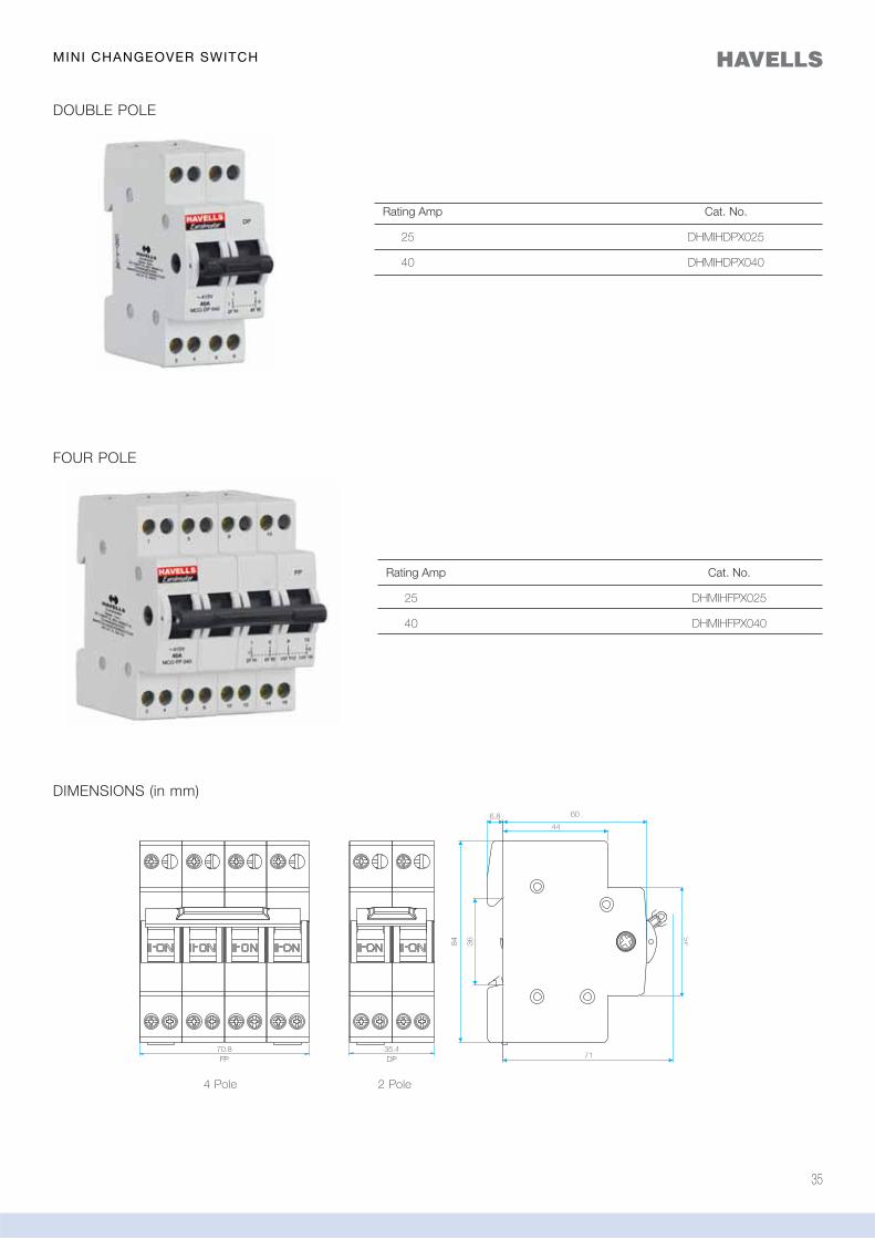
DOUBLE POLE
FOUR POLE
DIMENSIONS (in mm)
Rating Amp Cat. No.
25 DHMIHDPX025
40 DHMIHDPX040
Rating Amp Cat. No.
25 DHMIHFPX025
40 DHMIHFPX040
2 Pole4 Pole
MINI CHANGEOVER SWITCH

36
The flow of current through electrical facilities
always involves risks. Poorly insulated
equipment, faulty wires and incorrect use of an
electrical device cause currents to flow through
the wrong path (i.e. through the insulation) to the
earth. This current is called ‘Leakage Current’.
Earth leakage is an electrical hazard and is
responsible for electrical shocks and fire risk.
Earth leakage and its associated hazard can be
prevented by Residual Current Circuit Breaker
(RCCB), also popularly known as Earth Leakage
Circuit Breaker (ELCB).
Range 16A - 63A
Sensitivity30mA, 100mA, 300mA, 500mA
ExecutionDouble Pole (2P)Four Pole (4P)
Specification
IEC 61008-1/IS 12640 - 1:2000 / EN 61008-1
Features
connection
37
Residual Current Circuit Breaker(RCCB) 16A - 63A
38
Rated Tripping Current Maximum permissible earth
of the RCD fault loop impedance in
10mA 5,000
30mA 1,666
100mA 500
300mA 166
PROTECTION
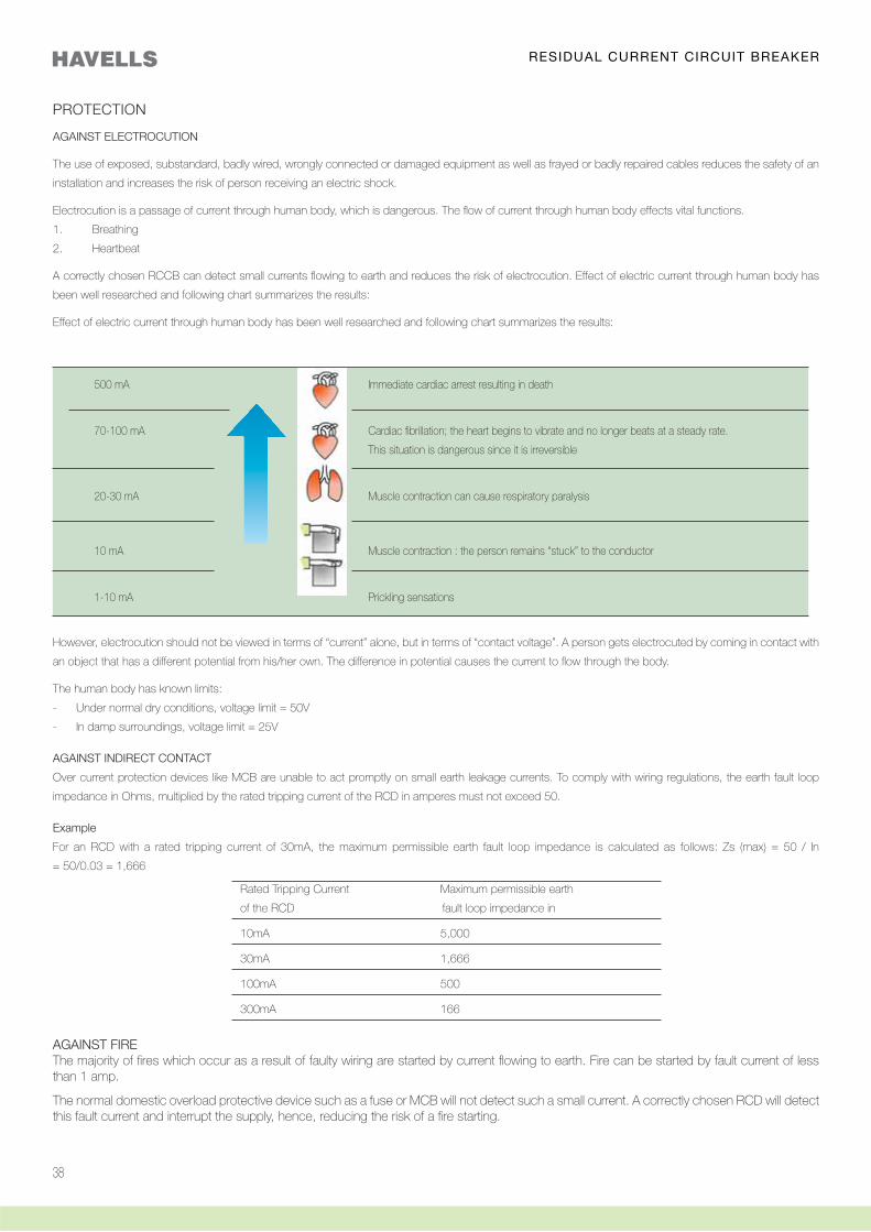
500 mA Immediate cardiac arrest resulting in death
70-100 mA Cardiac fibrillation; the heart begins to vibrate and no longer beats at a steady rate.
This situation is dangerous since it is irreversible
20-30 mA Muscle contraction can cause respiratory paralysis
10 mA Muscle contraction : the person remains “stuck” to the conductor
1-10 mA Prickling sensations
AGAINST ELECTROCUTION
The use of exposed, substandard, badly wired, wrongly connected or damaged equipment as well as frayed or badly repaired cables reduces the safety of an
installation and increases the risk of person receiving an electric shock.
Electrocution is a passage of current through human body, which is dangerous. The flow of current through human body effects vital functions.
1. Breathing
2. Heartbeat
A correctly chosen RCCB can detect small currents flowing to earth and reduces the risk of electrocution. Effect of electric current through human body has
been well researched and following chart summarizes the results:
Effect of electric current through human body has been well researched and following chart summarizes the results:
However, electrocution should not be viewed in terms of “current” alone, but in terms of “contact voltage”. A person gets electrocuted by coming in contact with
an object that has a different potential from his/her own. The difference in potential causes the current to flow through the body.
The human body has known limits:
- Under normal dry conditions, voltage limit = 50V
- In damp surroundings, voltage limit = 25V
AGAINST INDIRECT CONTACT
Over current protection devices like MCB are unable to act promptly on small earth leakage currents. To comply with wiring regulations, the earth fault loop
impedance in Ohms, multiplied by the rated tripping current of the RCD in amperes must not exceed 50.
Example
For an RCD with a rated tripping current of 30mA, the maximum permissible earth fault loop impedance is calculated as follows: Zs (max) = 50 / In
= 50/0.03 = 1,666
AGAINST FIREThe majority of fires which occur as a result of faulty wiring are started by current flowing to earth. Fire can be started by fault current of less than 1 amp.
The normal domestic overload protective device such as a fuse or MCB will not detect such a small current. A correctly chosen RCD will detect this fault current and interrupt the supply, hence, reducing the risk of a fire starting.
RESIDUAL CURRENT CIRCUIT BREAKER
39
WORKING PRINCIPLE
TECHNICAL INFORMATION
The RCCB works on the current balance principle. The supply conductors, i.e. the phases
and the neutral, are passed through a torroid and form the primary windings of a current
transformer. Its secondary winding is connected to a highly sensitive electromagnetic trip relay,
which operates the trip mechanism.
In a healthy circuit, sum of the currents in phases, is equal to the current in the neutral and
the vector sum of all currents is equal to zero. If there is any insulation fault in the current and
leakage current flows to earth, the currents do not balance and their vector sum is not equal
to zero. This imbalance is detected by the core balanced current transformer, the RCCB is
tripped and supply to load is interrupted. The trip mechanism is operated at a residual current
between 50-100% of its rated tripping current.
FOUR POLE
Standard Conformity IS 12640-1: IEC 61008-1 IS 12640-1: IEC 61008-1
Rated Current (In) A 16, 25, 32, 40, 63 25, 40, 63
Sensitivity (I n) mA 30, 100, 300, 500 30, 100, 300, 500
Rated Voltage (Un) Vac 240 415
Rated Insulation Voltage (Ui) V 660 660
Rated Frequency Hz 50 50
Short circuit Withstand Capacity kA 6 6
Residual Making Breaking Capacity A 500 A or 10 In wherever is greater 500 A or 10 In wherever is greater
Ambient Temperature oC -25°C to + 55°C -25°C to + 55°C
Shock Resistance 40 mm free fall 40 mm free fall
Vibration Resistance g 3 3
Electrical /Mechanical operations 10000 10000
Mounting Din Rail (35 x 7.5) mm Din Rail (35 x 7.5) mm
Degree of Protection IP 20 IP 20
Terminal Capacity (max) mm2 25 25
*500 mA is available on request
TWO POLE
RESIDUAL CURRENT CIRCUIT BREAKER
40
SELECTION
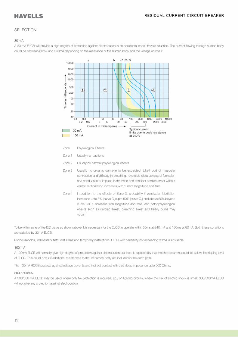
30 mA
A 30 mA ELCB will provide a high degree of protection against electrocution in an accidental shock hazard situation. The current flowing through human body
could be between 80mA and 240mA depending on the resistance of the human body and the voltage across it.
Zone Physiological Effects
Zone 1 Usually no reactions
Zone 2 Usually no harmful physiological effects
Zone 3 Usually no organic damage to be expected. Likelihood of muscular
contraction and difficulty in breathing, reversible disturbances of formation
and conduction of impulse in the heart and transient cardiac arrest without
ventricular fibrillation increases with current magnitude and time.
Zone 4 In addition to the effects of Zone 3, probability if ventricular fabriliation
increased upto 5% (curve C2) upto 50% (curve C
3) and above 50% beyond
curve C3. It increases with magnitude and time, and pathophysiological
effects such as cardiac arrest, breathing arrest and heavy burns may
occur.
To be within zone of the IEC curve as shown above. It is necessary for the ELCB to operate within 50ms at 240 mA and 150ms at 80mA. Both these conditions
are satisfied by 30mA ELCB.
For households, individual outlets, wet areas and temporary installations, ELCB with sensitivity not exceeding 30mA is advisable.
100 mA
A 100mA ELCB will normally give high degree of protection against electrocution but there is a possibility that the shock current could fall below the tripping level
of ELCB. This could occur if additional resistances to that of human body are included in the earth path.
The 100mA RCCB protects against leakage currents and indirect contact with earth loop impedance upto 500 Ohms.
300 / 500mA
A 300/500 mA ELCB may be used where only fire protection is required. eg., on lighting circuits, where the risk of electric shock is small. 300/500mA ELCB
will not give any protection against electrocution.
RESIDUAL CURRENT CIRCUIT BREAKER
41
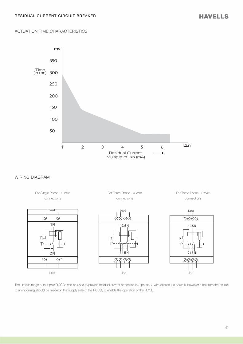
ACTUATION TIME CHARACTERISTICS
WIRING DIAGRAM
The Havells range of four pole RCCBs can be used to provide residual current protection in 3 phase, 3 wire circuits (no neutral), however a link from the neutral
to an incoming should be made on the supply side of the RCCB, to enable the operation of the RCCB.
For Single Phase - 2 Wire
connections
For Three Phase - 4 Wire
connections
For Three Phase - 3 Wire
connections
Line Line Line
RESIDUAL CURRENT CIRCUIT BREAKER
42
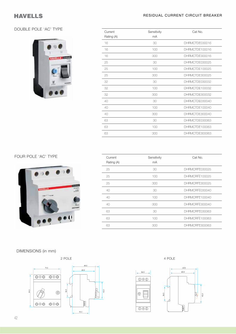
DOUBLE POLE ‘AC’ TYPE
FOUR POLE ‘AC’ TYPE
RESIDUAL CURRENT CIRCUIT BREAKER
2 POLE 4 POLE
DIMENSIONS (in mm)
Current Sensitivity Cat No.
Rating (A) mA
16 30 DHRMCTDE030016
16 100 DHRMCTDE100016
16 300 DHRMCTDE300016
25 30 DHRMCTDE030025
25 100 DHRMCTDE100025
25 300 DHRMCTDE300025
32 30 DHRMCTDE030032
32 100 DHRMCTDE100032
32 300 DHRMCTDE300032
40 30 DHRMCTDE030040
40 100 DHRMCTDE100040
40 300 DHRMCTDE300040
63 30 DHRMCTDE030063
63 100 DHRMCTDE100063
63 300 DHRMCTDE300063
Current Sensitivity Cat No.
Rating (A) mA
25 30 DHRMCRFE030025
25 100 DHRMCRFE100025
25 300 DHRMCRFE300025
40 30 DHRMCRFE030040
40 100 DHRMCRFE100040
40 300 DHRMCRFE300040
63 30 DHRMCRFE030063
63 100 DHRMCRFE100063
63 300 DHRMCRFE300063
43
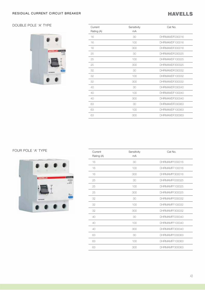
DOUBLE POLE ‘A’ TYPE
FOUR POLE ‘A’ TYPE
Current Sensitivity Cat No.
Rating (A) mA
16 30 DHRMAMDF030016
16 100 DHRMAMDF100016
16 300 DHRMAMDF300016
25 30 DHRMAMDF030025
25 100 DHRMAMDF100025
25 300 DHRMAMDF300025
32 30 DHRMAMDF030032
32 100 DHRMAMDF100032
32 300 DHRMAMDF300032
40 30 DHRMAMDF030040
40 100 DHRMAMDF100040
40 300 DHRMAMDF300040
63 30 DHRMAMDF030063
63 100 DHRMAMDF100063
63 300 DHRMAMDF300063
Current Sensitivity Cat No.
Rating (A) mA
16 30 DHRMAMFF030016
16 100 DHRMAMFF100016
16 300 DHRMAMFF300016
25 30 DHRMAMFF030025
25 100 DHRMAMFF100025
25 300 DHRMAMFF300025
32 30 DHRMAMFF030032
32 100 DHRMAMFF100032
32 300 DHRMAMFF300032
40 30 DHRMAMFF030040
40 100 DHRMAMFF100040
40 300 DHRMAMFF300040
63 30 DHRMAMFF030063
63 100 DHRMAMFF100063
63 300 DHRMAMFF300063
RESIDUAL CURRENT CIRCUIT BREAKER

44
The flow of current through electrical facilities
always involves risks. Poorly insulated
equipment, faulty wires and incorrect use of an
electrical device cause currents to flow through
the wrong path (i.e. through the insulation) to the
earth. This current is called ‘Leakage Current’.
Earth leakage is an electrical hazard and is
responsible for electrical shocks and fire risk.
Earth leakage and its associated hazard can
be prevented by residual current circuit breaker
(RCCB), also popularly known as Earth Leakage
Circuit Breaker (ELCB).
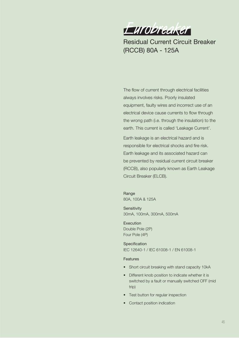
Range 80A, 100A & 125A
Sensitivity30mA, 100mA, 300mA, 500mA
ExecutionDouble Pole (2P)Four Pole (4P)
Specification
IEC 12640-1 / IEC 61008-1 / EN 61008-1
Features
switched by a fault or manually switched OFF (mid trip)
45
Residual Current Circuit Breaker(RCCB) 80A - 125A
46
TECHNICAL SPECIFICATION
DOUBLE POLE FOUR POLE
Specification Reference IEC 61008-1 & IS 12640-1: 2000 IEC 61008-1 & IS 12640-1: 2000
Rated current (In) A 80, 100, 125 80, 100 , 125
Sensitivity (IΔn) mA 30, 100, 300 30, 100 ,300, 500*
Rated Voltage (Ue) V 240 V~ 415V~
Rated Insulation voltage (Ui) V 660 660
Rated Frequency Hz 50 50
Trip Time IxIΔn<300ms, 5IΔn<40ms
Short circuit withstand Capacity kA 10 10
Residual Making Breaking capacity A 10 In 10 In
Ambient Working Temperature oC -25°C to + 55°C -25°C to + 55°C
Shock Resistance 40mm free fall 40mm free fall
Vibration Resistance g 5 5
Electrical Endurance operations >2000 >2000
Mechanical Endurance operations >3000 >3000
Mounting Din Rail (35 x7.5 mm) Din Rail (35 x7.5 mm)
Degree of protection IP 20 IP 20
Terminals Capacity (Max) mm2 50 50
*500mA on request
RESIDUAL CURRENT CIRCUIT BREAKER(80A - 125A RCCB)
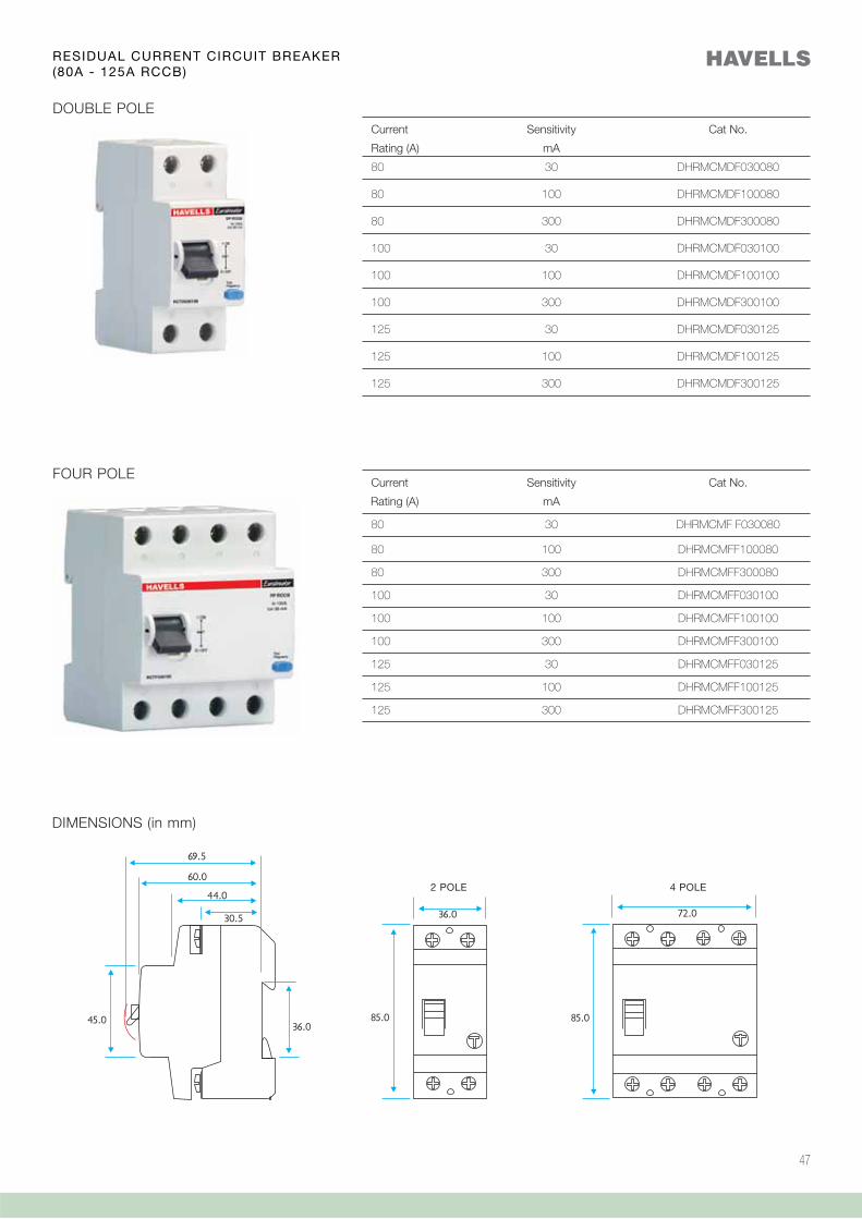
47
DOUBLE POLE
FOUR POLE
Current Sensitivity Cat No.
Rating (A) mA
80 30 DHRMCMDF030080
80 100 DHRMCMDF100080
80 300 DHRMCMDF300080
100 30 DHRMCMDF030100
100 100 DHRMCMDF100100
100 300 DHRMCMDF300100
125 30 DHRMCMDF030125
125 100 DHRMCMDF100125
125 300 DHRMCMDF300125
Current Sensitivity Cat No.
Rating (A) mA
80 30 DHRMCMF F030080
80 100 DHRMCMFF100080
80 300 DHRMCMFF300080
100 30 DHRMCMFF030100
100 100 DHRMCMFF100100
100 300 DHRMCMFF300100
125 30 DHRMCMFF030125
125 100 DHRMCMFF100125
125 300 DHRMCMFF300125
DIMENSIONS (in mm)
RESIDUAL CURRENT CIRCUIT BREAKER(80A - 125A RCCB)
2 POLE 4 POLE

48
Havells New RCBO is a single composite device
which provides protection against over currents
and earth leakage faults in the same width and
profile as that of a standard MCB. It is designed
for use in domestic, commercial and industrial
distribution systems at the most downstream
circuit for ensuring high degree of protection to
the user for a particular circuit. In normal use, it
is safe to use and free of to user as well as to
environment.
Range 6A, 10A, 16A, 20A, 25A, 32A & 40A
Sensitivity30mA, 100mA, 300mA
ExecutionSingle Pole with neutral (SPN)Triple Pole with neutral (TPN)
Specification
IS:12640 Part2, IEC 61009-1, BSEN:61009-1
Features
49
Residual Current Circuit Breakerwith Overload and Short CircuitProtection
50
CONSTRUCTION
Havells new RCBO is a single composite device which provides protection against over currents and earth leakage faults in the same width and profile as that
of a standard MCB. It is designed for use in domestic, commercial and industrial distribution systems at the most downstream circuit for ensuring high degree
of protection to the user for a particular circuit. In normal use, it is safe to use and poses no threat to user as well as to environment.
FEATURES
Positive contact indication: Red for ON , Green for OFF
Short circuit breaking capacity 10 kA.
Large terminal capacity: RCBOs have 35 mm2 for cool running while in operation.
Protection in case of loss of supply neutral: Even in event of loss of supply neutral, Havells RCBO provides protection against earth faults . The Functional
Earth (FE) white color wire connected to earth provides this protection.
Controlled response & immunity to nuisance tripping: The trip level and the response time of the Havells VD (Voltage Dependent) RCBO using electronic
circuit is set to very precise values and thereby provide greater immunity to nuisance tripping that can be caused by mains borne noise, surge voltages,
lighting surges, reactive loads, mains filters, etc.
Neutral to earth faults: A connection that occurs between N and E on the load side of any RCBO will impact on its performance and cause the trip level
to increase. In the case of a N - E fault, the user may have no way of knowing that this fault exists and that the RCBO has been desensitised. Under this
condition, the Havells VD RCBO provides a far greater level of protection than a normal VI (Voltage Independent) RCBO.
Aesthetics & Convenience
The new module’s unique compact construction enables far more devices to be fitted into a distribution board than previously possible, and 2 Module
RCBO can simply replace existing MCB 2 pole when upgrading a board.
High stacking density = smaller chasis & distribution boards.
Reliability & continuity of service
Enhanced discrimination with Havells MCBs
Back up to 10 kA with BS & DIN fuses
Retrofits Havells MCBs in distribution boards with no modifications in general
Robust construction.
Energy limiting
Havells RCBO meets the requirements for energy let through by IEC & British Standard for energy limiting class 3.
RESIDUAL CURRENT CIRCUIT BREAKER WITH OVER LOAD & SHORT CIRCUIT PROTECTION
ADDITIONAL RANGE - TYPE A & S
Type A - Pulsating DC Protection: Any electrical appliance with power control has the ability to produce earth fault currents with pulsating DC (rectified AC)
components. RCBOs that provide this type of protection are referred to as Type A RCBOs.
Standard VI RCBOs do not provide this protection, and are referred to as Type AC RCBOs. Havells VD RCBOs have been specifically designed to provide
protection against pulsating DC fault currents.
Type S- Selective or Time Delay: RCBOs are also divided into two categories determined by their response time to an earth fault current, as follows
General Type - having a trip time<300mS for fault currents of IDn and < 40ms for fault currents > 5IDn.
S Type- having a trip time of 150 - 500mS for IDn, and 40 - 130mS for >5IDn.
(IDn is the rated residual operating current of the RCBO)
As the name implies, general types are intended for general purpose use. However, S (selective) types are normally used in conjunction with downstream general
type RCBOs.
The S type effectively provides discrimination in terms of the response time to earth fault currents for upstream ad downstream RCBOs. For example, when two
RCBOs are connected in series the first RCBO will often be an S type.
51
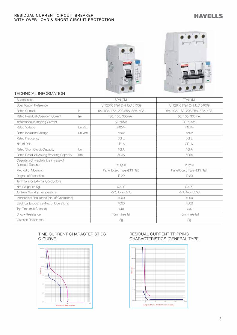
TECHNICAL INFORMATION
Specification SPN (2M) TPN (4M)
Specification Reference IS 12640 (Part 2) & IEC 61009 IS 12640 (Part 2) & IEC 61009
Rated Current In 6A, 10A, 16A, 20A,25A, 32A, 40A 6A, 10A, 16A, 20A,25A, 32A, 40A
Rated Residual Operating Current IΔn 30, 100, 300mA. 30, 100, 300mA.
Instantaneous Tripping Current ‘C ’curve ‘C ’curve
Rated Voltage Un Vac 240V~ 415V~
Rated Insulation Voltage Un Vac 660V 660V
Rated Frequency 50Hz 50Hz
No. of Pole 1P+N 3P+N
Rated Short Circuit Capacity Icn 10kA 10kA
Rated Residual Making Breaking Capacity IΔm 500A 500A
Operating Characteristics in case of Residual Currents ‘A’ type ‘A’ type
Method of Mounting Panel Board Type (DIN Rail) Panel Board Type (DIN Rail)
Degree of Protection IP 20 IP 20
Terminals for External Conductors
Net Weight (in Kg) 0.420 0.420
Ambient Working Temperature -5°C to + 55°C -5°C to + 55°C
Mechanical Endurance (No. of Operations) 4000 4000
Electrical Endurance (No. of Operations) 4000 4000
Trip Time (milli Second) <40 <40
Shock Resistance 40mm free fall 40mm free fall
Vibration Resistance 3g 3g
RESIDUAL CURRENT CIRCUIT BREAKER WITH OVER LOAD & SHORT CIRCUIT PROTECTION
TIME CURRENT CHARACTERISTICSC CURVE
RESIDUAL CURRENT TRIPPING CHARACTERISTICS (GENERAL TYPE)
52
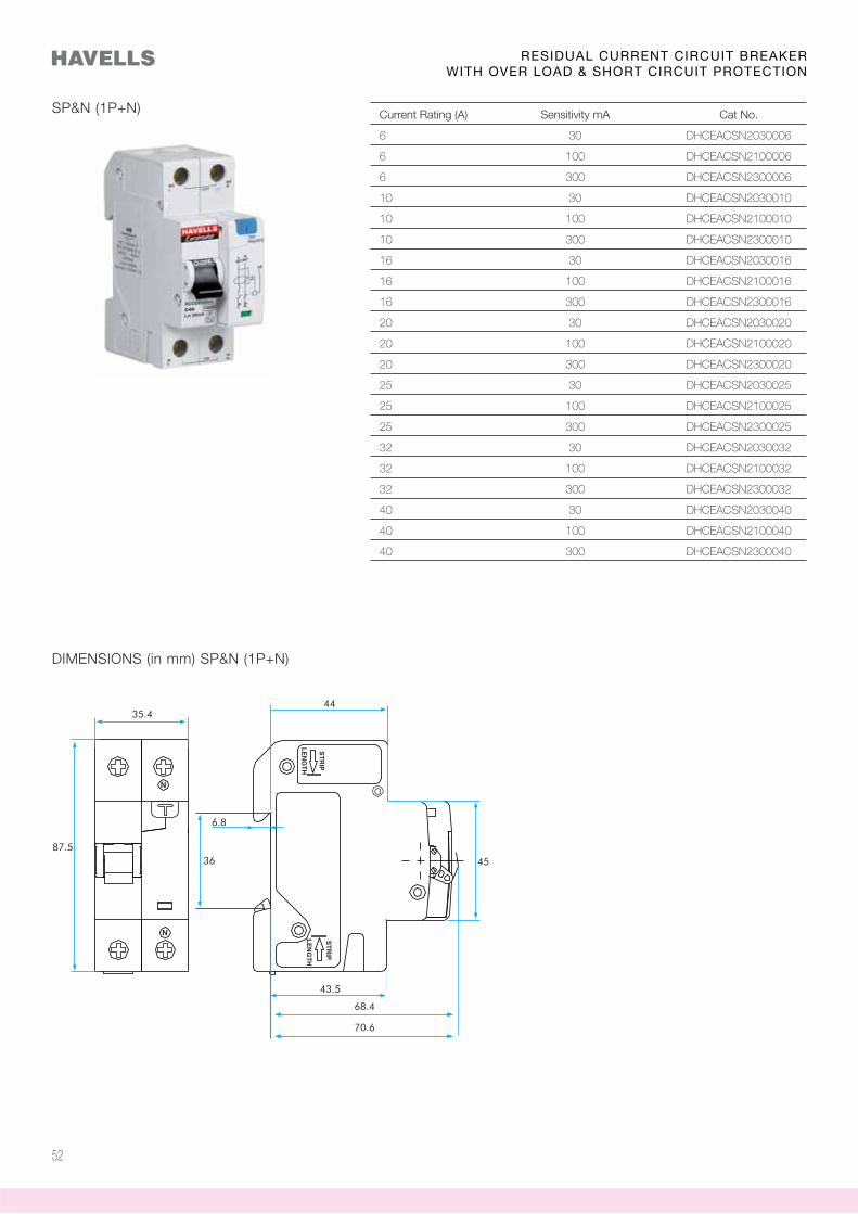
Current Rating (A) Sensitivity mA Cat No.
6 30 DHCEACSN2030006
6 100 DHCEACSN2100006
6 300 DHCEACSN2300006
10 30 DHCEACSN2030010
10 100 DHCEACSN2100010
10 300 DHCEACSN2300010
16 30 DHCEACSN2030016
16 100 DHCEACSN2100016
16 300 DHCEACSN2300016
20 30 DHCEACSN2030020
20 100 DHCEACSN2100020
20 300 DHCEACSN2300020
25 30 DHCEACSN2030025
25 100 DHCEACSN2100025
25 300 DHCEACSN2300025
32 30 DHCEACSN2030032
32 100 DHCEACSN2100032
32 300 DHCEACSN2300032
40 30 DHCEACSN2030040
40 100 DHCEACSN2100040
40 300 DHCEACSN2300040
SP&N (1P+N)
DIMENSIONS (in mm) SP&N (1P+N)
RESIDUAL CURRENT CIRCUIT BREAKER WITH OVER LOAD & SHORT CIRCUIT PROTECTION
53
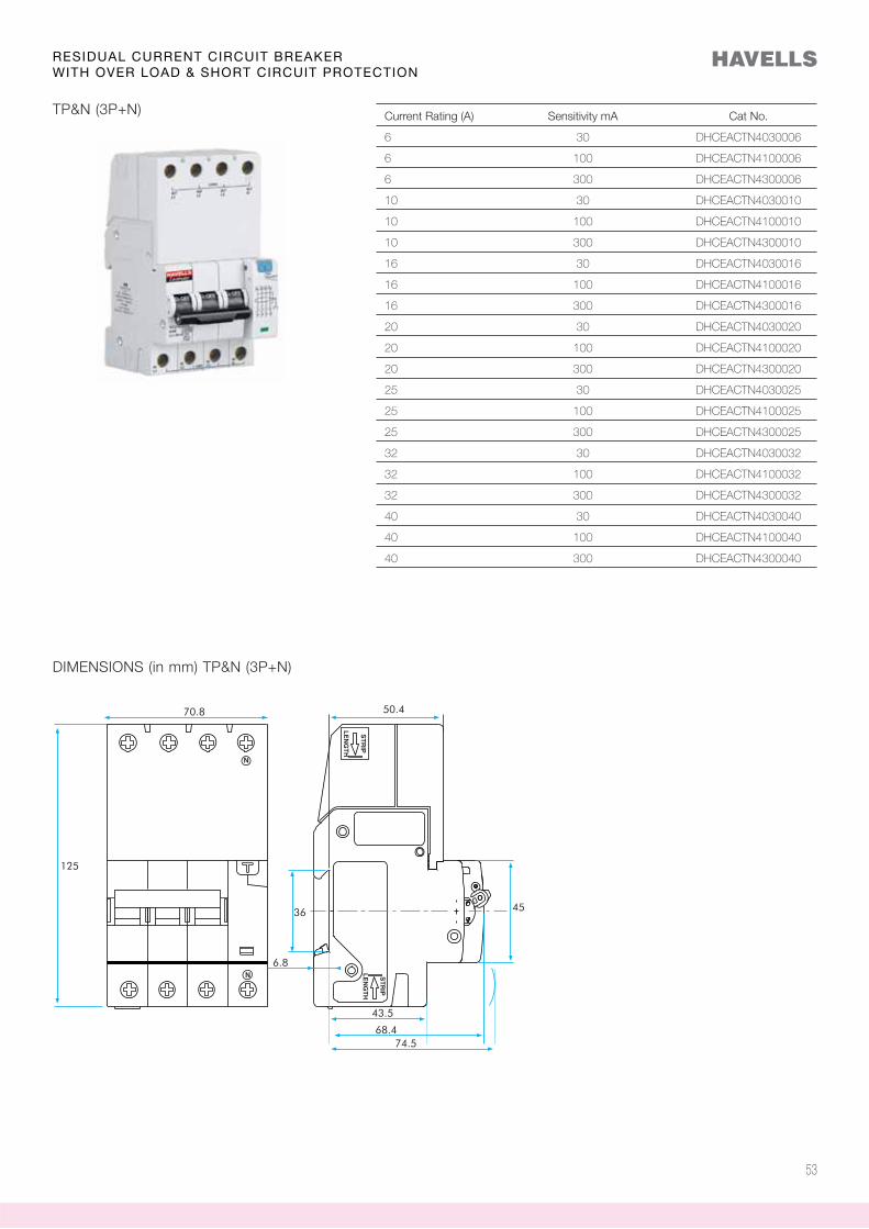
Current Rating (A) Sensitivity mA Cat No.
6 30 DHCEACTN4030006
6 100 DHCEACTN4100006
6 300 DHCEACTN4300006
10 30 DHCEACTN4030010
10 100 DHCEACTN4100010
10 300 DHCEACTN4300010
16 30 DHCEACTN4030016
16 100 DHCEACTN4100016
16 300 DHCEACTN4300016
20 30 DHCEACTN4030020
20 100 DHCEACTN4100020
20 300 DHCEACTN4300020
25 30 DHCEACTN4030025
25 100 DHCEACTN4100025
25 300 DHCEACTN4300025
32 30 DHCEACTN4030032
32 100 DHCEACTN4100032
32 300 DHCEACTN4300032
40 30 DHCEACTN4030040
40 100 DHCEACTN4100040
40 300 DHCEACTN4300040
TP&N (3P+N)
DIMENSIONS (in mm) TP&N (3P+N)
RESIDUAL CURRENT CIRCUIT BREAKER WITH OVER LOAD & SHORT CIRCUIT PROTECTION

54
Electrical energy has brought along with it a lot of conveniences, beyond imagination. It’s consumption has increased manifold be it in domestic, commercial or industrial applications, there by creating a need for scientific & effective method of distribution.
The purpose of electrical wiring is to systematically distribute current. In the process the system mainly adopts methods to protect installation and human life from electrical hazards such as short circuit, overload and earth leakage.
The electrical wiring is carried out to distribute current from a single source of supply to various circuits, such an arrangement is made inside an enclosure called Distribution Board.
The Distribution Board is not merely an enclosure but a comprehensive system in itself, comprising of copper bus bars, brass neutral links, earth links to facilitate effective distribution of current. It incorporates safety devices such as MCBs, ELCBs and Isolators, which serves to protect the installation.
A wide range of compact, elegant & economical DBs with unique features, designed & engineered to provide user safety, convenience and operational / maintenance advantages are offered.
Range Single Phase & Three Phase Distribution Boards
SpecificationIS 13032 /IS 8623
Features
your home décor
MCB + RCCB, Changeover + RCCB, Isolator + RCCB + TPN RCBO
only that phase where the earth leakage exist gets isolated. This feature avoids the total outage and allows the other two healthy phases to remain ON.
gland plates at the top and bottom with knockouts on the sides of DB to increase the flexibility of cables / conduit entry from all directions
Neutral Links, Earth Links, Bus Bar and inter connecting wires / links
bottom two of Round type for mounting or hanging the DB
the DBs suitable for wider applications, minimizing sharp bends of cables
for facilitating individual earthing for each outgoing terminal
of mounting 20A SP and 20A TP / 30A TP sockets on the sides of DB as additional provision
construction.
55
Distribution Board DB
56
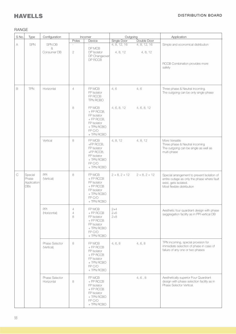
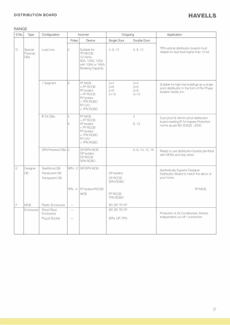
RANGE
S No. Type Configuration Incomer Outgoing Application Poles Device Single Door Double Door A SPN SPN DB - - 4, 8, 12, 16 4, 8, 12, 16 Simple and economical distribution & DP MCB Consumer DB 2 DP Isolator 4, 8, 12 4, 8, 12 DP Changeover DP RCCB RCCB Combination provides more safety
B TPN Horizontal 4 FP MCB 4, 6 4, 6 Three phase & Neutral incoming. FP Isolator The outgoing can be only single phase FP RCCB TPN RCBO 8 FP MCB 4, 6, 8, 12 4, 6, 8, 12 + FP RCCB, FP Isolator + FP RCCB, FP Isolator + TPN RCBO FP C/O + TPN RCBO
Vertical 8 FP MCB 4, 8, 12 4, 8, 12 More Versatile +FP RCCB, Three phase & Neutral incoming FP Isolator The outgoing can be single as well as +FP RCCB, multi-phase FP Isolator + TPN RCBO FP C/O + TPN RCBO
C Special PPI 8 FP MCB 2 + 8, 2 + 12 2 + 8, 2 + 12 Phase (Vertical) + FP RCCB Application FP Isolator DBs + FP RCCB FP Isolator + TPN RCBO FP C/O + TPN RCBO
PPI 4 FP MCB 2+4 (Horizontal) 4 + FP RCCB 2+6 8 FP Isolator 2+8 + FP RCCB FP Isolator + TPN RCBO FP C/O + TPN RCBO
Phase Selector 8 FP MCB 4, 6, 8 4, 6, 8 (Vertical) + FP RCCB FP Isolator + FP RCCB FP Isolator + TPN RCBO FP C/O + TPN RCBO Phase Selector FP MCB 4, 6 , 8 Horizontal 8 + FP RCCB FP Isolator + FP RCCB FP Isolator + TPN RCBO FP C/O + TPN RCBO
Special arrangement to prevent Isolation of entire outage as only the phase where fault exist, gets isolated.Most flexible distribution
TPN incoming, special provision for immediate selection of phase in case of failure of any one or two phases
Aesthetic four quardrant design with phase seggregation facility as in PPI vertical DB
DISTRIBUTION BOARD
Aesthetically superior Four Quardrant design with phase selection facility as in Phase Selector Vertical.
57
DISTRIBUTION BOARD
RANGE S No. Type Configuration Incomer Outgoing Application
Poles Device Single Door Double Door
D Special Load Line 3 Suitable for 4, 8, 12 4, 8, 12 Purpose TP MCCB DBs ‘G’ frame 80A, 100A, 125A with 10KA or 16KA Breaking Capacity
7 Segment 8 FP MCB 2+4 2+4 + FP RCCB 2+6 2+6 FP Isolator 2+8 2+8 + FP RCCB 2+12 2+12 FP Isolator + TPN RCBO FP C/O + TPN RCBO
IP 54 DBs 4 FP MCB 4 + FP RCCB 8 FP Isolator 8, 12 + FP RCCB FP Isolator + TPN RCBO FP C/O + TPN RCBO
SPN Prewired DBs 2 DP/SPN MCB 6, 8, 10, 12, 16 DP Isolator, DP RCCB SPN RCBO
E Designer TeakWood DB SPN : 2 DP/SPN MCB
DB Translucent DB DP Isolator,
Transparent DB DP RCCB SPN RCBO
TPN : 4 FP Isolator/RCCB/ FP MCB,
MCB FP RCCB TPN RCBO
F MCB Plastic Enclosures — SP, DP, TP, FP
Enclosures Sheet Steel — SP, DP, TP, FP Enclosures
Plug & Socket — SPN, DP, TPN
Dust proof & Vermin proof distribution board meeting IP-54 Ingress Protection norms as per IEC 60529 : 2000.
Ready to use distribution boards pre-fitted with MCBs and duly wired.
Aesthetically Superior Designer Distribution Board to match the décor of your home.
TPN vertical distribution boards most reliable for fault level higher than 10 kA.
Suitable for high-rise buildings as a single point distribution in the form of Per Phase Isolation facility too.
Protection of Air Conditioners, Motors.Independent cut-off / connection
58
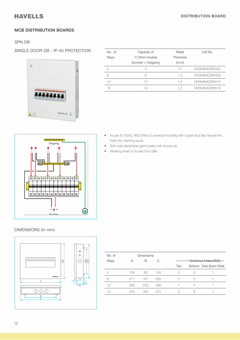
DISTRIBUTION BOARD
SPN DB
DIMENSIONS (in mm)
No. of Dimensions
Ways A B C Knockout Holes (Ø25)
Top Bottom Side (Each Side)
4 139 89 154 3 3 1
8 211 161 226 5 5 1
12 283 233 298 7 7 1
16 355 305 370 9 9 1
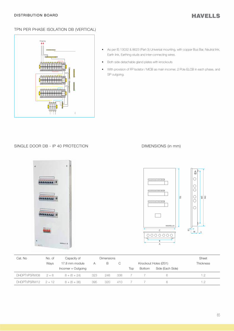
SINGLE DOOR DB - IP-40 PROTECTION No,. of Capacity of Sheet Cat No.
Ways 17.8mm module Thickness
Incomer + Outgoing (m.m)
4 4 1.0 DHDMSHOSRW04
8 8 1.0 DHDMSHOSRW08
12 12 1.0 DHDMSHOSRW12
16 16 1.2 DHDMSHOSRW16
Earth link, Earthing studs.
MCB DISTRIBUTION BOARDS
59
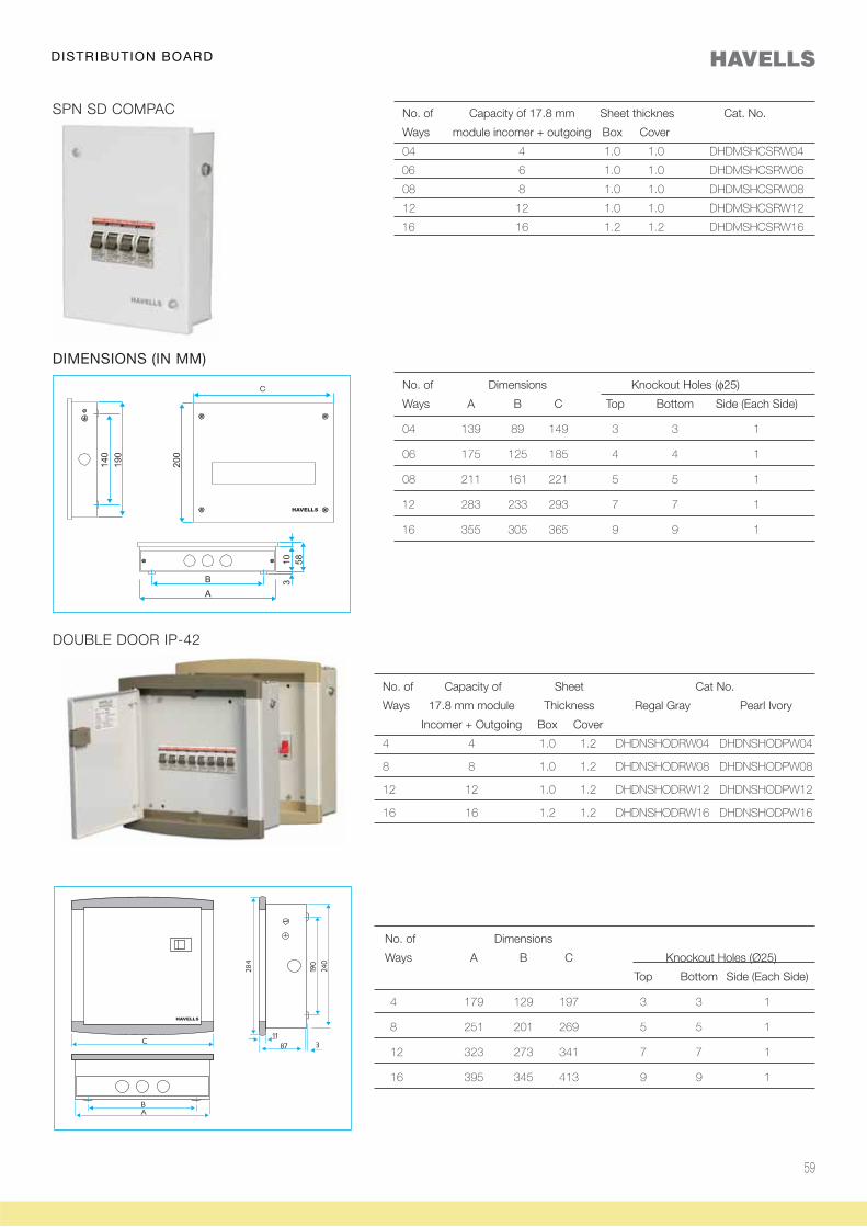
DISTRIBUTION BOARD
No. of Capacity of 17.8 mm Sheet thicknes Cat. No.
Ways module incomer + outgoing Box Cover
04 4 1.0 1.0 DHDMSHCSRW04
06 6 1.0 1.0 DHDMSHCSRW06
08 8 1.0 1.0 DHDMSHCSRW08
12 12 1.0 1.0 DHDMSHCSRW12
16 16 1.2 1.2 DHDMSHCSRW16
SPN SD COMPAC
DIMENSIONS (IN MM)
No. of Dimensions Knockout Holes (φ25)
Ways A B C Top Bottom Side (Each Side)
04 139 89 149 3 3 1
06 175 125 185 4 4 1
08 211 161 221 5 5 1
12 283 233 293 7 7 1
16 355 305 365 9 9 1
No. of Capacity of Sheet Cat No.
Ways 17.8 mm module Thickness Regal Gray Pearl Ivory
Incomer + Outgoing Box Cover
4 4 1.0 1.2 DHDNSHODRW04 DHDNSHODPW04
8 8 1.0 1.2 DHDNSHODRW08 DHDNSHODPW08
12 12 1.0 1.2 DHDNSHODRW12 DHDNSHODPW12
16 16 1.2 1.2 DHDNSHODRW16 DHDNSHODPW16
No. of Dimensions
Ways A B C Knockout Holes (Ø25)
Top Bottom Side (Each Side)
4 179 129 197 3 3 1
8 251 201 269 5 5 1
12 323 273 341 7 7 1
16 395 345 413 9 9 1
DOUBLE DOOR IP-42
60
SPN DB WITH ACRYLIC WINDOW
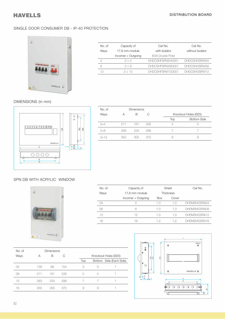
No. of Dimensions
Ways A B C Knockout Holes (Ø25)
Top Bottom Side (Each Side)
04 139 89 154 3 3 1
08 211 161 226 5 5 1
12 283 233 298 7 7 1
16 355 305 370 9 9 1
No. of Capacity of Sheet Cat No.
Ways 17.8 mm module Thickness
Incomer + Outgoing Box Cover
04 4 1.0 1.0 DHDMSHOSRA04
08 8 1.0 1.0 DHDMSHOSRA08
12 12 1.0 1.0 DHDMSHOSRA12
16 16 1.2 1.2 DHDMSHOSRA16
DISTRIBUTION BOARD
SINGLE DOOR CONSUMER DB - IP-40 PROTECTION
No. of Capacity of Cat No. Cat No.
Ways 17.8 mm module with Isolator without Isolator
Incomer + Outgoing (63A Double Pole)
4 2 + 4 DHDCSHFSRW040001 DHDCSHOSRW04
8 2 + 8 DHDCSHFSRW080001 DHDCSHOSRW08
12 2 + 12 DHDCSHFSRW120001 DHDCSHOSRW12
DIMENSIONS (in mm)
No. of Dimensions
Ways A B C Knockout Holes (Ø25)
Top Bottom Side
2+4 211 161 226 5 5
2+8 283 233 298 7 7
2+12 355 305 370 9 9
61
No. of Dimensions
Ways A B C Knockout Holes (Ø25)
Top Bottom Side (Each Side)
04 175 125 197 3 3 1
08 247 197 269 5 5 1
12 319 269 341 7 7 1
16 391 341 413 9 9 1
DISTRIBUTION BOARD
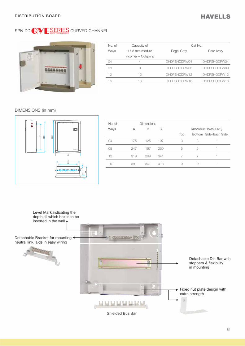
SPN DD CURVED CHANNEL
DIMENSIONS (in mm)
No. of Capacity of Cat No.
Ways 17.8 mm module Regal Gray Pearl Ivory
Incomer + Outgoing
04 4 DHDPSHODRW04 DHDPSHODPW04
08 8 DHDPSHODRW08 DHDPSHODPW08
12 12 DHDPSHODRW12 DHDPSHODPW12
16 16 DHDPSHODRW16 DHDPSHODPW16
62
DISTRIBUTION BOARD
SINGLE DOOR DIMENSIONS (in mm)
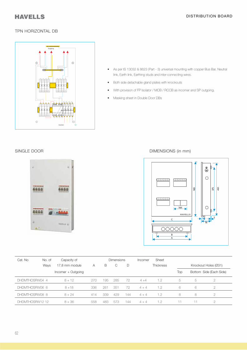
Cat. No No. of Capacity of Dimensions Incomer Sheet
Ways 17.8 mm module A B C D Thickness Knockout Holes (Ø31)
Incomer + Outgoing Top Bottom Side (Each Side)
DHDMTHOSRW04 4 8 + 12 270 195 285 72 4 +4 1.2 5 5 2
DHDMTHOSRW06 6 8 +18 336 261 351 72 4 + 4 1.2 6 6 2
DHDMTHOSRW08 8 8 + 24 414 339 429 144 4 + 4 1.2 8 8 2
DHDMTHOSRW12 12 8 + 36 558 483 573 144 4 + 4 1.2 11 11 2
link, Earth link, Earthing studs and inter-connecting wires.
TPN HORIZONTAL DB
63
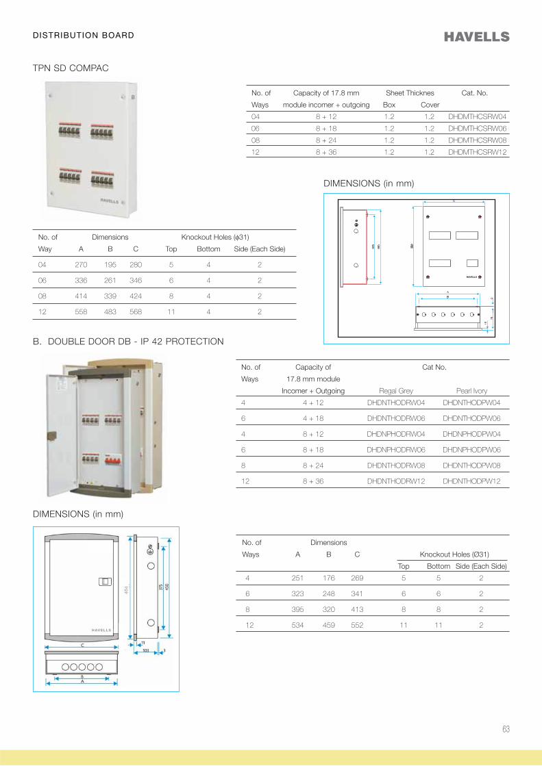
B. DOUBLE DOOR DB - IP 42 PROTECTION
No. of Capacity of Cat No.
Ways 17.8 mm module
Incomer + Outgoing Regal Grey Pearl Ivory
4 4 + 12 DHDNTHODRW04 DHDNTHODPW04
6 4 + 18 DHDNTHODRW06 DHDNTHODPW06
4 8 + 12 DHDNPHODRW04 DHDNPHODPW04
6 8 + 18 DHDNPHODRW06 DHDNPHODPW06
8 8 + 24 DHDNTHODRW08 DHDNTHODPW08
12 8 + 36 DHDNTHODRW12 DHDNTHODPW12
DIMENSIONS (in mm)
No. of Dimensions
Ways A B C Knockout Holes (Ø31)
Top Bottom Side (Each Side)
4 251 176 269 5 5 2
6 323 248 341 6 6 2
8 395 320 413 8 8 2
12 534 459 552 11 11 2
DISTRIBUTION BOARD
TPN SD COMPAC
DIMENSIONS (in mm)
No. of Dimensions Knockout Holes (φ31)
Way A B C Top Bottom Side (Each Side)
04 270 195 280 5 4 2
06 336 261 346 6 4 2
08 414 339 424 8 4 2
12 558 483 568 11 4 2
No. of Capacity of 17.8 mm Sheet Thicknes Cat. No.
Ways module incomer + outgoing Box Cover
04 8 + 12 1.2 1.2 DHDMTHCSRW04
06 8 + 18 1.2 1.2 DHDMTHCSRW06
08 8 + 24 1.2 1.2 DHDMTHCSRW08
12 8 + 36 1.2 1.2 DHDMTHCSRW12
484
HAVELLS
64
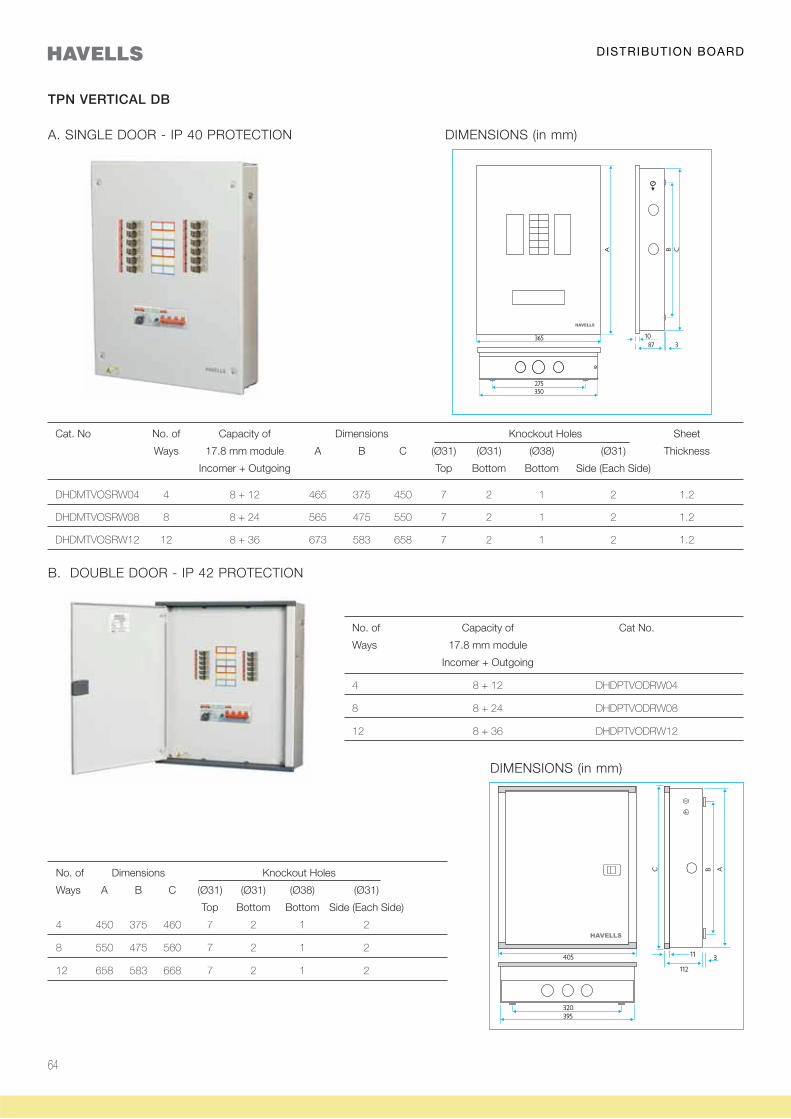
A. SINGLE DOOR - IP 40 PROTECTION DIMENSIONS (in mm)
TPN VERTICAL DB
Cat. No No. of Capacity of Dimensions Knockout Holes Sheet
Ways 17.8 mm module A B C (Ø31) (Ø31) (Ø38) (Ø31) Thickness
Incomer + Outgoing Top Bottom Bottom Side (Each Side)
DHDMTVOSRW04 4 8 + 12 465 375 450 7 2 1 2 1.2
DHDMTVOSRW08 8 8 + 24 565 475 550 7 2 1 2 1.2
DHDMTVOSRW12 12 8 + 36 673 583 658 7 2 1 2 1.2
B. DOUBLE DOOR - IP 42 PROTECTION
No. of Capacity of Cat No.
Ways 17.8 mm module
Incomer + Outgoing
4 8 + 12 DHDPTVODRW04
8 8 + 24 DHDPTVODRW08
12 8 + 36 DHDPTVODRW12
DIMENSIONS (in mm)
No. of Dimensions Knockout Holes
Ways A B C (Ø31) (Ø31) (Ø38) (Ø31)
Top Bottom Bottom Side (Each Side)
4 450 375 460 7 2 1 2
8 550 475 560 7 2 1 2
12 658 583 668 7 2 1 2
DISTRIBUTION BOARD
65
TPN PER PHASE ISOLATION DB (VERTICAL)
Earth link, Earthing studs and inter-connecting wires.
SP outgoing.
SINGLE DOOR DB - IP 40 PROTECTION DIMENSIONS (in mm)
Cat. No No. of Capacity of Dimensions Sheet
Ways 17.8 mm module A B C Knockout Holes (Ø31) Thickness
Incomer + Outgoing Top Bottom Side (Each Side)
DHDPTVPSRW08 2 + 8 8 + (6 + 24) 323 248 338 7 7 6 1.2
DHDPTVPSRW12 2 + 12 8 + (6 + 36) 395 320 410 7 7 6 1.2
DISTRIBUTION BOARD
66
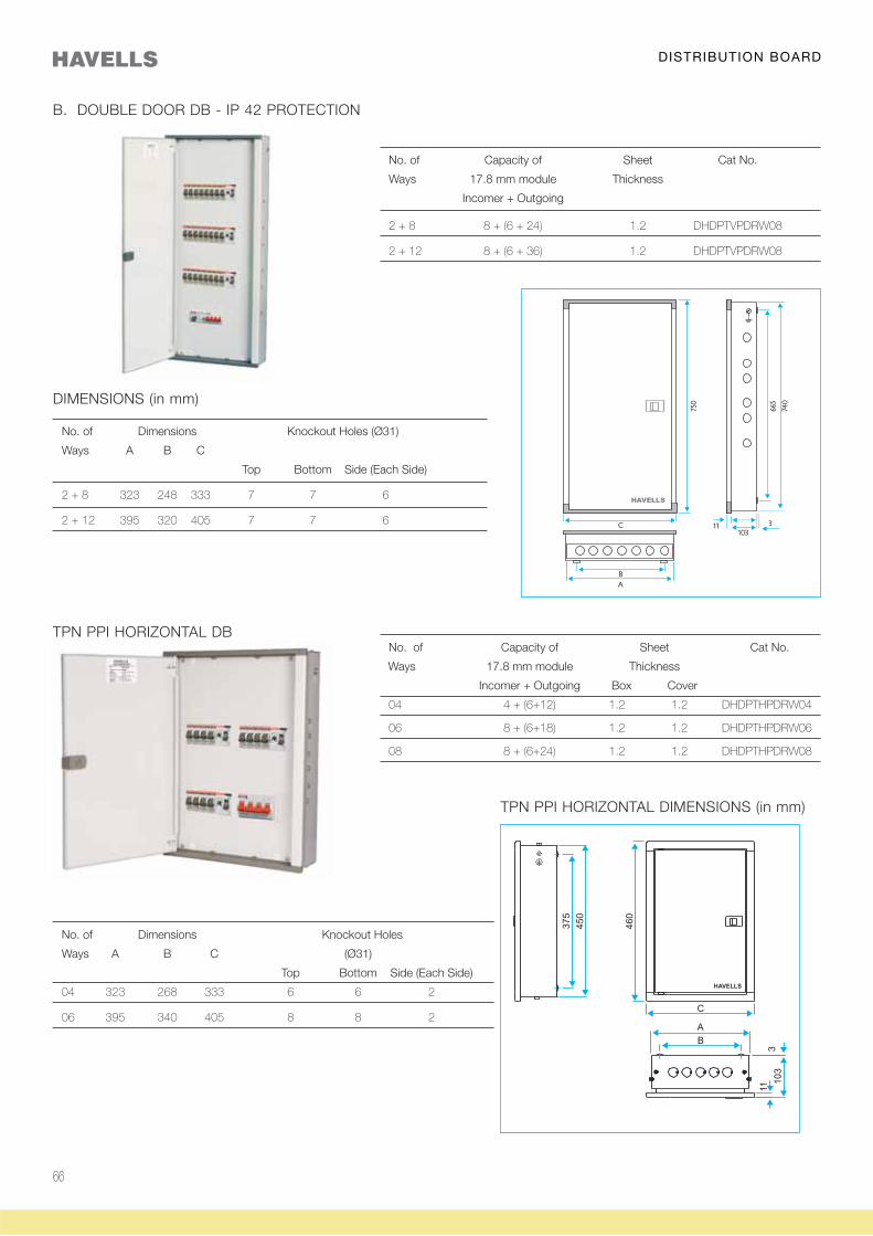
B. DOUBLE DOOR DB - IP 42 PROTECTION
No. of Capacity of Sheet Cat No.
Ways 17.8 mm module Thickness
Incomer + Outgoing
2 + 8 8 + (6 + 24) 1.2 DHDPTVPDRW08
2 + 12 8 + (6 + 36) 1.2 DHDPTVPDRW08
DIMENSIONS (in mm)
No. of Dimensions Knockout Holes (Ø31)
Ways A B C
Top Bottom Side (Each Side)
2 + 8 323 248 333 7 7 6
2 + 12 395 320 405 7 7 6
TPN PPI HORIZONTAL DB No. of Capacity of Sheet Cat No.
Ways 17.8 mm module Thickness
Incomer + Outgoing Box Cover
04 4 + (6+12) 1.2 1.2 DHDPTHPDRW04
06 8 + (6+18) 1.2 1.2 DHDPTHPDRW06
08 8 + (6+24) 1.2 1.2 DHDPTHPDRW08
No. of Dimensions Knockout Holes
Ways A B C (Ø31)
Top Bottom Side (Each Side)
04 323 268 333 6 6 2
06 395 340 405 8 8 2
TPN PPI HORIZONTAL DIMENSIONS (in mm)
DISTRIBUTION BOARD
67
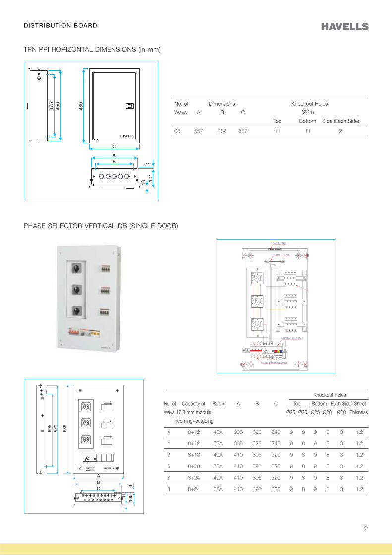
No. of Dimensions Knockout Holes
Ways A B C (Ø31)
Top Bottom Side (Each Side)
08 557 482 587 11 11 2
TPN PPI HORIZONTAL DIMENSIONS (in mm)
PHASE SELECTOR VERTICAL DB (SINGLE DOOR)
Knockout Holes
No. of Capacity of Rating A B C Top Bottom Each Side Sheet
Ways 17.8 mm module Ø25 Ø20 Ø25 Ø20 Ø20 Thikness
Incoming+outgoing
4 8+12 40A 338 323 248 9 8 9 8 3 1.2
4 8+12 63A 338 323 248 9 8 9 8 3 1.2
6 8+18 40A 410 395 320 9 8 9 8 3 1.2
6 8+18 63A 410 395 320 9 8 9 8 3 1.2
8 8+24 40A 410 395 320 9 8 9 8 3 1.2
8 8+24 63A 410 395 320 9 8 9 8 3 1.2
DISTRIBUTION BOARD
68
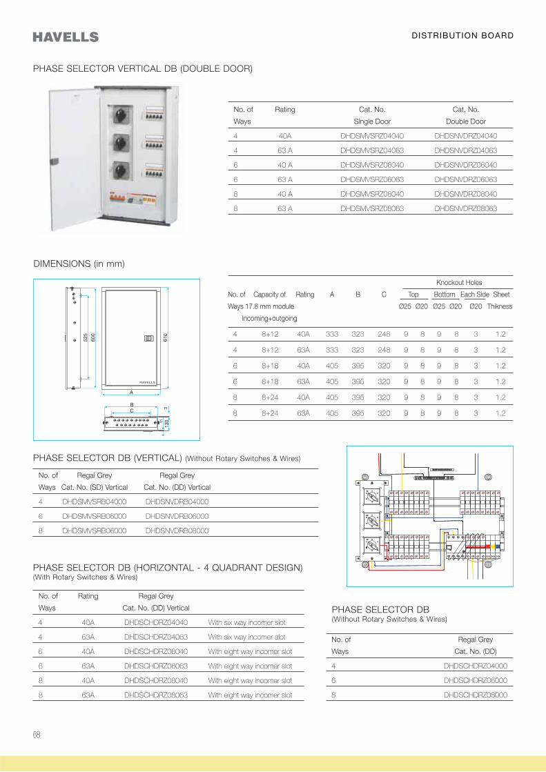
DIMENSIONS (in mm)
Knockout Holes
No. of Capacity of Rating A B C Top Bottom Each Side Sheet
Ways 17.8 mm module Ø25 Ø20 Ø25 Ø20 Ø20 Thikness
Incoming+outgoing
4 8+12 40A 333 323 248 9 8 9 8 3 1.2
4 8+12 63A 333 323 248 9 8 9 8 3 1.2
6 8+18 40A 405 395 320 9 8 9 8 3 1.2
6 8+18 63A 405 395 320 9 8 9 8 3 1.2
8 8+24 40A 405 395 320 9 8 9 8 3 1.2
8 8+24 63A 405 395 320 9 8 9 8 3 1.2
No. of Regal Grey Regal Grey
Ways Cat. No. (SD) Vertical Cat. No. (DD) Vertical
4 DHDSMVSRB04000 DHDSNVDRB04000
6 DHDSMVSRB06000 DHDSNVDRB06000
8 DHDSMVSRB06000 DHDSNVDRB08000
PHASE SELECTOR DB (VERTICAL) (Without Rotary Switches & Wires)
No. of Rating Regal Grey
Ways Cat. No. (DD) Vertical
4 40A DHDSCHDRZ04040 With six way incomer slot
4 63A DHDSCHDRZ04063 With six way incomer slot
6 40A DHDSCHDRZ06040 With eight way incomer slot
6 63A DHDSCHDRZ06063 With eight way incomer slot
8 40A DHDSCHDRZ08040 With eight way incomer slot
8 63A DHDSCHDRZ08063 With eight way incomer slot
PHASE SELECTOR DB (HORIZONTAL - 4 QUADRANT DESIGN)(With Rotary Switches & Wires)
No. of Regal Grey
Ways Cat. No. (DD)
4 DHDSCHDRZ04000
6 DHDSCHDRZ06000
8 DHDSCHDRZ08000
PHASE SELECTOR DB(Without Rotary Switches & Wires)
No. of Rating Cat. No. Cat. No.
Ways Single Door Double Door
4 40A DHDSMVSRZ04040 DHDSNVDRZ04040
4 63 A DHDSMVSRZ04063 DHDSNVDRZ04063
6 40 A DHDSMVSRZ06040 DHDSNVDRZ06040
6 63 A DHDSMVSRZ06063 DHDSNVDRZ06063
8 40 A DHDSMVSRZ08040 DHDSNVDRZ08040
8 63 A DHDSMVSRZ08063 DHDSNVDRZ08063
PHASE SELECTOR VERTICAL DB (DOUBLE DOOR)
DISTRIBUTION BOARD
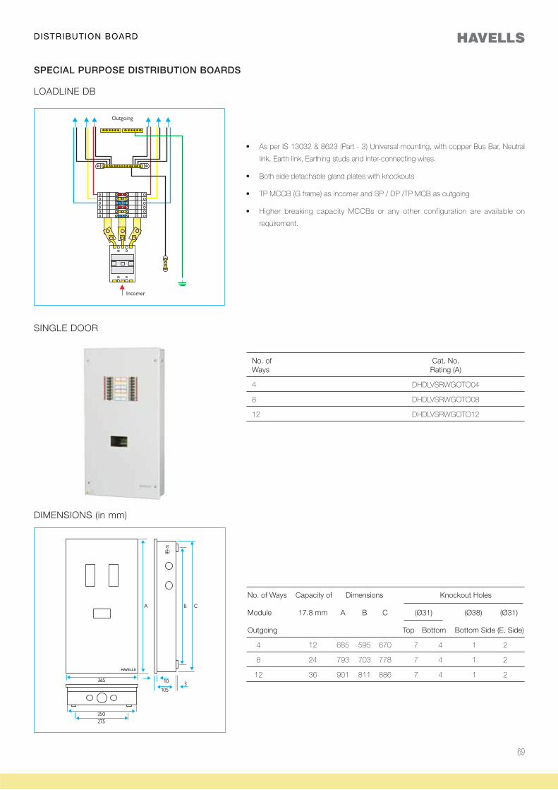
69
SINGLE DOOR
No. of Cat. No. Ways Rating (A)
4 DHDLVSRWGOTO04
8 DHDLVSRWGOTO08
12 DHDLVSRWGOTO12
LOADLINE DB
SPECIAL PURPOSE DISTRIBUTION BOARDS
link, Earth link, Earthing studs and inter-connecting wires.
requirement.
DIMENSIONS (in mm)
No. of Ways Capacity of Dimensions Knockout Holes
Module 17.8 mm A B C (Ø31) (Ø38) (Ø31)
Outgoing Top Bottom Bottom Side (E. Side)
4 12 685 595 670 7 4 1 2
8 24 793 703 778 7 4 1 2
12 36 901 811 886 7 4 1 2
DISTRIBUTION BOARD
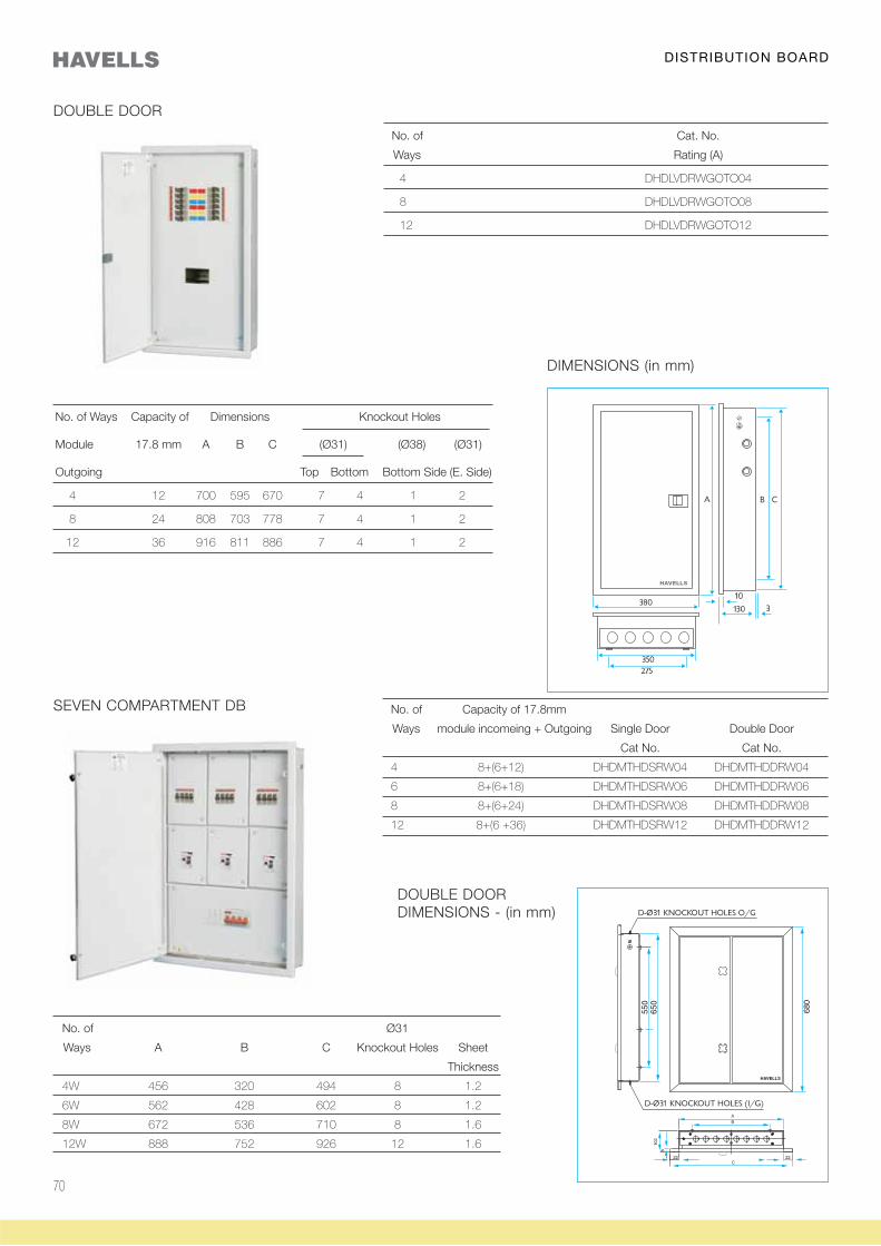
70
DOUBLE DOOR
No. of Cat. No.
Ways Rating (A)
4 DHDLVDRWGOTO04
8 DHDLVDRWGOTO08
12 DHDLVDRWGOTO12
DIMENSIONS (in mm)
SEVEN COMPARTMENT DB No. of Capacity of 17.8mm
Ways module incomeing + Outgoing Single Door Double Door
Cat No. Cat No.
4 8+(6+12) DHDMTHDSRW04 DHDMTHDDRW04
6 8+(6+18) DHDMTHDSRW06 DHDMTHDDRW06
8 8+(6+24) DHDMTHDSRW08 DHDMTHDDRW08
12 8+(6 +36) DHDMTHDSRW12 DHDMTHDDRW12
DOUBLE DOORDIMENSIONS - (in mm)
No. of Ø31
Ways A B C Knockout Holes Sheet
Thickness
4W 456 320 494 8 1.2
6W 562 428 602 8 1.2
8W 672 536 710 8 1.6
12W 888 752 926 12 1.6
DISTRIBUTION BOARD
No. of Ways Capacity of Dimensions Knockout Holes
Module 17.8 mm A B C (Ø31) (Ø38) (Ø31)
Outgoing Top Bottom Bottom Side (E. Side)
4 12 700 595 670 7 4 1 2
8 24 808 703 778 7 4 1 2
12 36 916 811 886 7 4 1 2
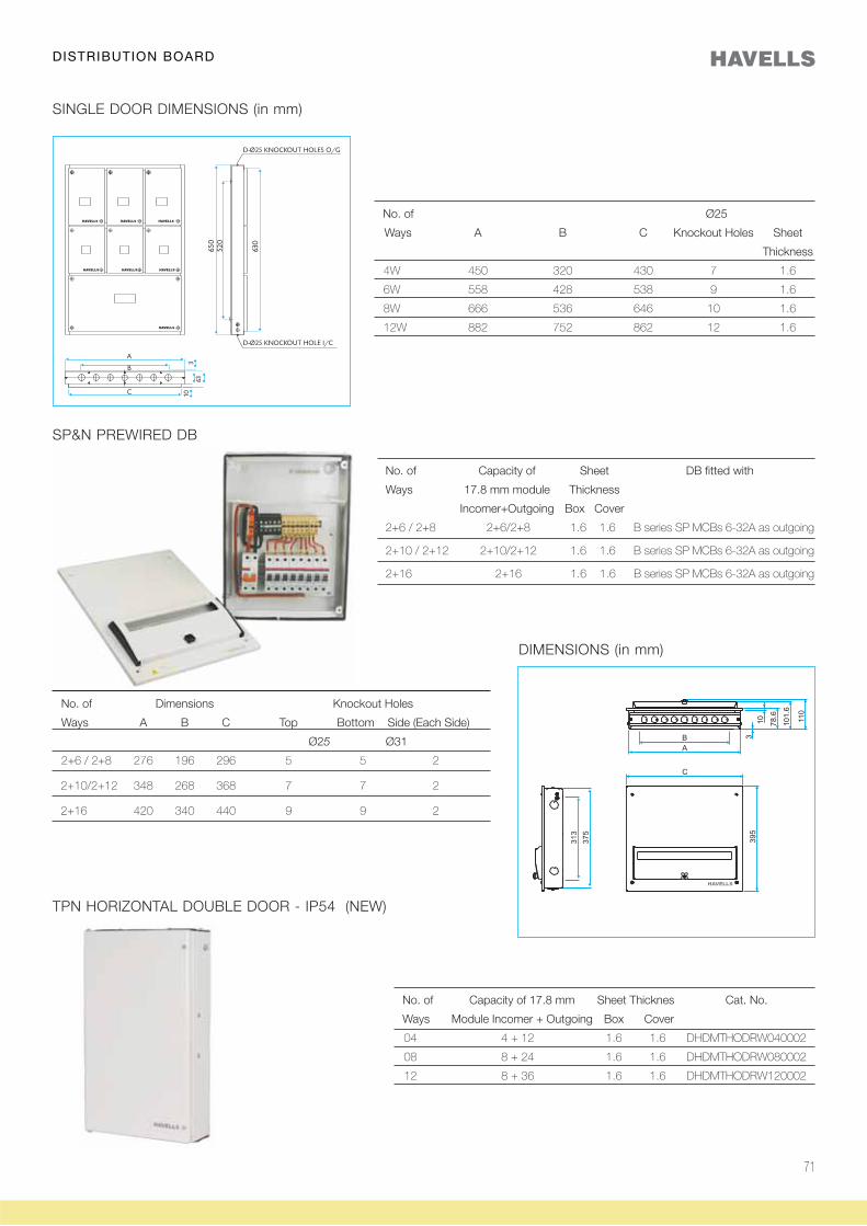
71
No. of Ø25
Ways A B C Knockout Holes Sheet
Thickness
4W 450 320 430 7 1.6
6W 558 428 538 9 1.6
8W 666 536 646 10 1.6
12W 882 752 862 12 1.6
SP&N PREWIRED DB
SINGLE DOOR DIMENSIONS (in mm)
DIMENSIONS (in mm)
No. of Dimensions Knockout Holes
Ways A B C Top Bottom Side (Each Side)
Ø25 Ø31
2+6 / 2+8 276 196 296 5 5 2
2+10/2+12 348 268 368 7 7 2
2+16 420 340 440 9 9 2
No. of Capacity of Sheet DB fitted with
Ways 17.8 mm module Thickness
Incomer+Outgoing Box Cover
2+6 / 2+8 2+6/2+8 1.6 1.6 B series SP MCBs 6-32A as outgoing
2+10 / 2+12 2+10/2+12 1.6 1.6 B series SP MCBs 6-32A as outgoing
2+16 2+16 1.6 1.6 B series SP MCBs 6-32A as outgoing
TPN HORIZONTAL DOUBLE DOOR - IP54 (NEW)
No. of Capacity of 17.8 mm Sheet Thicknes Cat. No.
Ways Module Incomer + Outgoing Box Cover
04 4 + 12 1.6 1.6 DHDMTHODRW040002
08 8 + 24 1.6 1.6 DHDMTHODRW080002
12 8 + 36 1.6 1.6 DHDMTHODRW120002
DISTRIBUTION BOARD
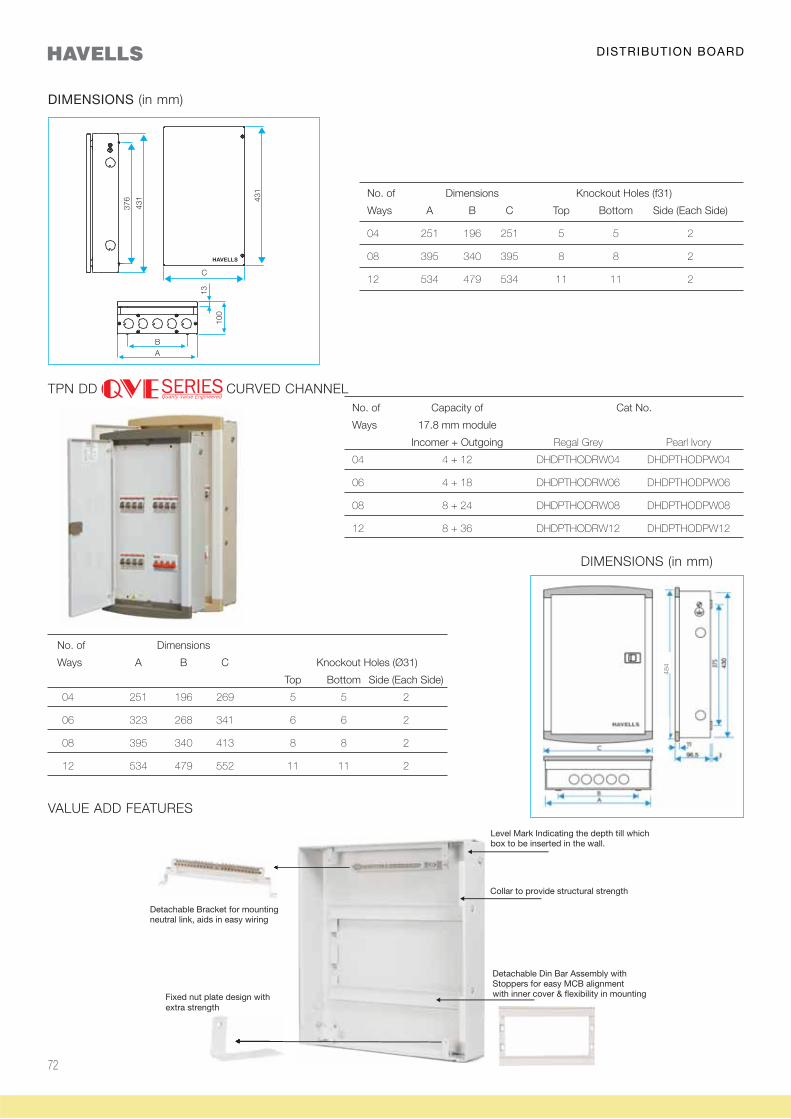
72
No. of Dimensions Knockout Holes (f31)
Ways A B C Top Bottom Side (Each Side)
04 251 196 251 5 5 2
08 395 340 395 8 8 2
12 534 479 534 11 11 2
DIMENSIONS (in mm)
No. of Capacity of Cat No.
Ways 17.8 mm module
Incomer + Outgoing Regal Grey Pearl Ivory
04 4 + 12 DHDPTHODRW04 DHDPTHODPW04
06 4 + 18 DHDPTHODRW06 DHDPTHODPW06
08 8 + 24 DHDPTHODRW08 DHDPTHODPW08
12 8 + 36 DHDPTHODRW12 DHDPTHODPW12
DIMENSIONS (in mm)
No. of Dimensions
Ways A B C Knockout Holes (Ø31)
Top Bottom Side (Each Side)
04 251 196 269 5 5 2
06 323 268 341 6 6 2
08 395 340 413 8 8 2
12 534 479 552 11 11 2
484
TPN DD CURVED CHANNEL
Fixed nut plate design withextra strength
VALUE ADD FEATURES
DISTRIBUTION BOARD
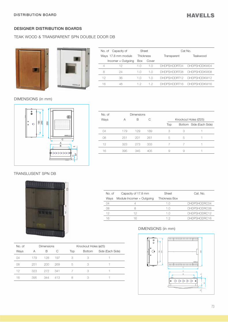
73
TEAK WOOD & TRANSPARENT SPN DOUBLE DOOR DB
DESIGNER DISTRIBUTION BOARDS
No. of Capacity of Sheet Cat No.
Ways 17.8 mm module Thickness Transparent Teakwood
Incomer + Outgoing Box Cover
4 12 1.0 1.0 DHDPSHODRT04 DHDPSHODKW04
8 24 1.0 1.0 DHDPSHODRT08 DHDPSHODKW08
12 36 1.0 1.0 DHDPSHODRT12 DHDPSHODKW12
16 48 1.2 1.2 DHDPSHODRT16 DHDPSHODKW16
No. of Dimensions
Ways A B C Knockout Holes (Ø25)
Top Bottom Side (Each Side)
04 179 129 189 3 3 1
08 251 201 261 5 5 1
12 323 273 333 7 7 1
16 395 345 405 9 9 1
DIMENSIONS (in mm)
No. of Capacity of 17.8 mm Sheet Cat. No.
Ways Module Incomer + Outgoing Thickness Box
04 4 1.0 DHDPSHODRC04
08 8 1.0 DHDPSHODRC08
12 12 1.0 DHDPSHODRC12
16 16 1.2 DHDPSHODRC16
No. of Dimensions Knockout Holes (φ25)
Ways A B C Top Bottom Side (Each Side)
04 179 128 197 3 3 1
08 251 200 269 5 3 1
12 323 272 341 7 3 1
16 395 344 413 8 3 1
TRANSLUSENT SPN DB
DIMENSIONS (in mm)
DISTRIBUTION BOARD
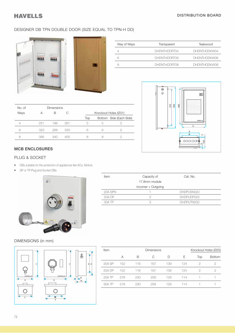
74
Way of Ways Transparent Teakwood
4 DHDNTHODRT04 DHDNTHODKW04
6 DHDNTHODRT06 DHDNTHODKW06
8 DHDNTHODRT08 DHDNTHODKW08
DESIGNER DB TPN DOUBLE DOOR (SIZE EQUAL TO TPN-H DD)
No. of Dimensions
Ways A B C Knockout Holes (Ø31)
Top Bottom Side (Each Side)
4 251 196 261 5 5 2
6 323 268 333 6 6 2
8 395 340 405 8 8 2
PLUG & SOCKET
MCB ENCLOSURES
Item Capacity of Cat. No.
17.8mm module
incomer + Outgoing
20A SPN 1 DHDPUSN020
20A DP 2 DHDPUDP020
30A TP 3 DHDPUTN030
DIMENSIONS (in mm)
Item Dimensions Knockout Holes (Ø25)
A B C D E Top Bottom
20A SP 152 116 167 139 124 2 2
20A DP 152 116 167 139 124 2 2
20A TP 278 230 293 129 114 1 1
30A TP 278 230 293 129 114 1 1
DISTRIBUTION BOARD
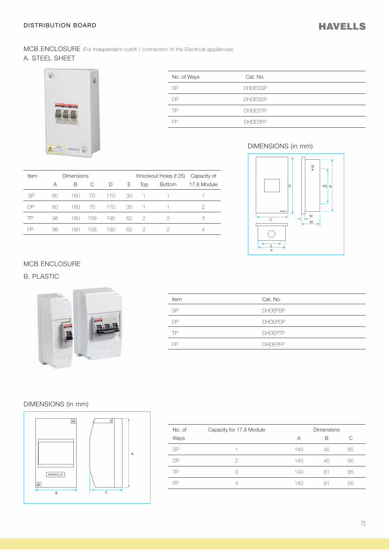
75
MCB ENCLOSURE (For Independent cutoff / connection of the Electrical appliances)
No. of Ways Cat. No.
SP DHDESSP
DP DHDESDP
TP DHDESTP
FP DHDESFP
A. STEEL SHEET
DIMENSIONS (in mm)
Item Dimensions Knockout Holes (f 25) Capacity of
A B C D E Top Bottom 17.8 Module
SP 60 160 70 170 30 1 1 1
DP 60 160 70 170 30 1 1 2
TP 98 180 108 190 62 2 2 3
FP 98 180 108 190 62 2 2 4
MCB ENCLOSURE
Item Cat. No.
SP DHDEPSP
DP DHDEPDP
TP DHDEPTP
FP DHDEPFP
B. PLASTIC
DIMENSIONS (in mm)
No. of Capacity for 17.8 Module Dimensions
Ways A B C
SP 1 140 45 65
DP 2 140 45 65
TP 3 140 81 65
FP 4 140 81 65
DISTRIBUTION BOARD
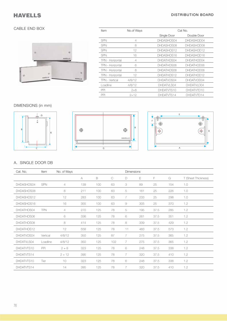
76
CABLE END BOX
DIMENSIONS (in mm)
Item No.of Ways Cat No.
Single Door Double Door
SPN 4 DHDASHOS04 DHDASHOD04
SPN 8 DHDASHOS08 DHDASHOD08
SPN 12 DHDASHOS12 DHDASHOD12
SPN 16 DHDASHOS16 DHDASHOD16
TPN - Horizontal 4 DHDATHOS04 DHDATHOD04
TPN - Horizontal 6 DHDATHOS06 DHDATHOD06
TPN - Horizontal 8 DHDATHOS08 DHDATHOD08
TPN - Horizontal 12 DHDATHOS12 DHDATHOD12
TPN - Vertical 4/8/12 DHDATVOS04 DHDATVOD04
Loadline 4/8/12 DHDATVLS04 DHDATVLD04
PPI 2+8 DHDATVTS10 DHDATVTD10
PPI 2+12 DHDATVTS14 DHDATVTD14
Cat. No. Item No. of Ways Dimensions
A B C D E F G T (Sheet Thickness)
DHDASHOS04 SPN 4 139 100 63 3 89 25 154 1.0
DHDASHOS08 8 211 100 63 5 161 25 226 1.0
DHDASHOS12 12 283 100 63 7 233 25 298 1.0
DHDASHOS16 16 355 100 63 9 305 25 370 1.2
DHDATHOS04 TPN 4 270 125 78 5 195 37.5 285 1.2
DHDATHOS06 6 336 125 78 6 261 37.5 351 1.2
DHDATHOS08 8 414 125 78 8 339 37.5 429 1.2
DHDATHOS12 12 558 125 78 11 483 37.5 573 1.2
DHDATVOS04 Vertical 4/8/12 350 125 87 7 275 37.5 365 1.2
DHDATVLS04 Loadline 4/8/12 350 125 102 7 275 37.5 365 1.2
DHDATVTS10 PPI 2 + 8 323 125 78 6 248 37.5 338 1.2
DHDATVTS14 2 + 12 395 125 78 7 320 37.5 410 1.2
DHDATVTS10 Tier 10 323 125 78 6 248 37.5 338 1.2
DHDATVTS14 14 395 125 78 7 320 37.5 410 1.2
A. SINGLE DOOR DB
DISTRIBUTION BOARD
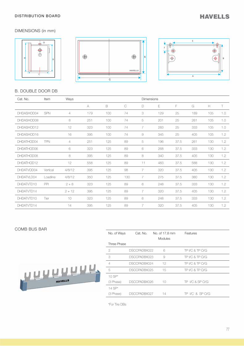
77
DIMENSIONS (in mm)
B. DOUBLE DOOR DB
Cat. No. Item Ways Dimensions
A B C D E F G H T
DHDASHOD04 SPN 4 179 100 74 3 129 25 189 105 1.0
DHDASHOD08 8 251 100 74 5 201 25 261 105 1.0
DHDASHOD12 12 323 100 74 7 283 25 333 105 1.0
DHDASHOD16 16 395 100 74 9 345 25 405 105 1.2
DHDATHOD04 TPN 4 251 125 89 5 196 37.5 261 130 1.2
DHDATHOD06 6 323 125 89 6 268 37.5 333 130 1.2
DHDATHOD08 8 395 125 89 8 340 37.5 405 130 1.2
DHDATHOD12 12 558 125 89 11 483 37.5 588 130 1.2
DHDATVOD04 Vertical 4/8/12 395 125 98 7 320 37.5 405 130 1.2
DHDATVLD04 Loadline 4/8/12 350 125 130 7 275 37.5 380 130 1.2
DHDATVTD10 PPI 2 + 8 323 125 89 6 248 37.5 333 130 1.2
DHDATVTD14 2 + 12 395 125 89 7 320 37.5 405 130 1.2
DHDATVTD10 Tier 10 323 125 89 6 248 37.5 333 130 1.2
DHDATVTD14 14 395 125 89 7 320 37.5 405 130 1.2
COMB BUS BARNo. of Ways Cat. No. No. of 17.8 mm Features
Modules
Three Phase
2 DSCCPADBX022 6 TP I/C & TP O/G
3 DSCCPADBX023 9 TP I/C & TP O/G
4 DSCCPADBX024 12 TP I/C & TP O/G
5 DSCCPADBX025 15 TP I/C & TP O/G
10 SP*
(3 Phase) DSCCPADBX026 10 TP I/C & SP O/G
14 SP*
(3 Phase) DSCCPADBX027 14 TP I/C & SP O/G
*For Tire DBs
DISTRIBUTION BOARD
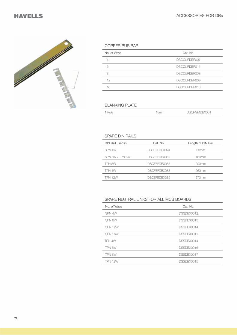
7878
COPPER BUS BAR
No. of Ways Cat. No.
4 DSCCUPDBP007
6 DSCCUPDBP011
8 DSCCUPDBP008
12 DSCCUPDBP009
16 DSCCUPDBP010
BLANKING PLATE
1 Pole 18mm DSCPGMDBX001
SPARE NEUTRAL LINKS FOR ALL MCB BOARDS
No. of Ways Cat. No.
SPN 4W DSSDBX0012
SPN 8W DSSDBX0013
SPN 12W DSSDBX0014
SPN 16W DSSDBX0011
TPN 4W DSSDBX0014
TPN 6W DSSDBX0016
TPN 8W DSSDBX0017
TPN 12W DSSDBX0015
SPARE DIN RAILS
DIN Rail used in Cat. No. Length of DIN Rail
SPN 4W DSCFEFDBX094 80mm
SPN 8W / TPN 6W DSCFEFDBX082 163mm
TPN 8W DSCFEFDBX085 200mm
TPN 4W DSCFEFDBX088 260mm
TPN 12W DSCEFEDBX089 273mm
ACCESSORIES FOR DBs
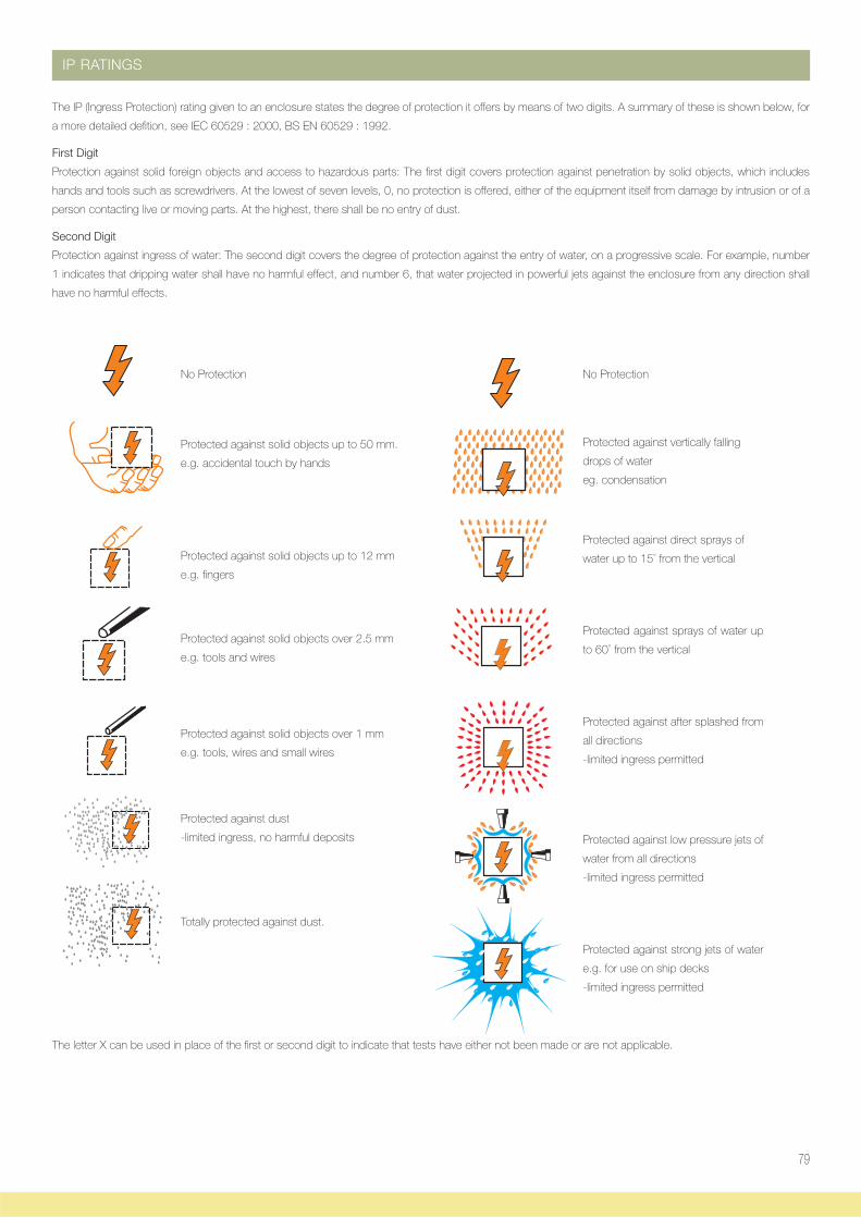
79
IP RATINGS
The IP (Ingress Protection) rating given to an enclosure states the degree of protection it offers by means of two digits. A summary of these is shown below, for
a more detailed defition, see IEC 60529 : 2000, BS EN 60529 : 1992.
First Digit
Protection against solid foreign objects and access to hazardous parts: The first digit covers protection against penetration by solid objects, which includes
hands and tools such as screwdrivers. At the lowest of seven levels, 0, no protection is offered, either of the equipment itself from damage by intrusion or of a
person contacting live or moving parts. At the highest, there shall be no entry of dust.
Second Digit
Protection against ingress of water: The second digit covers the degree of protection against the entry of water, on a progressive scale. For example, number
1 indicates that dripping water shall have no harmful effect, and number 6, that water projected in powerful jets against the enclosure from any direction shall
have no harmful effects.
No Protection
Protected against vertically falling
drops of water
eg. condensation
Protected against direct sprays of
water up to 15° from the vertical
Protected against sprays of water up
to 60° from the vertical
Protected against after splashed from
all directions
-limited ingress permitted
Protected against low pressure jets of
water from all directions
-limited ingress permitted
Protected against strong jets of water
e.g. for use on ship decks
-limited ingress permitted
The letter X can be used in place of the first or second digit to indicate that tests have either not been made or are not applicable.
No Protection
Protected against solid objects up to 50 mm.
e.g. accidental touch by hands
Protected against solid objects up to 12 mm
e.g. fingers
Protected against solid objects over 2.5 mm
e.g. tools and wires
Protected against solid objects over 1 mm
e.g. tools, wires and small wires
Protected against dust
-limited ingress, no harmful deposits
Totally protected against dust.
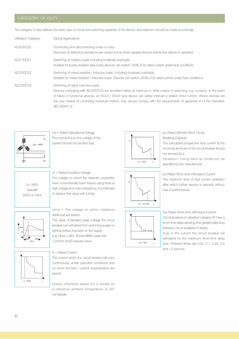
80
CATEGORY OF DUTY
The category of duty defines the basic type of circuit and switching capability of the device, and selection should be made accordingly.
Utilisation Category Typical Applications
AC20/DC20 Connecting and disconnecting under no-load.
Assumes all switching operations are carried out by other capable devices before this device is operated.
AC21/DC21 Switching of resistive loads including moderate overloads.
Suitable for purely resistive type loads devices can switch 150% of its rated current under fault conditions
AC22/DC22 Switching of mixed resistive / inductive loads, including moderate overloads.
Suitable for mixed resistive / inductive loads. Devices can switch 300% of its rated current under fault conditions.
AC23/DC23 Switching of highly inductive loads.
Devices complying with AC23/DC23 are provided mainly as back-up to other means of switching. e.g. contacts. In the event
of failure of functional devices, an AC23 / DC23 type device can safety interrupt a stalled motor current. Where devices are
the only means of controlling individual motors, they should comply with the requirements of appendix A of the standard.
(IEC 60947-3)
Ue = Rated Operational Voltage
The normal line-to-line voltage of the
system should not exceed (Ue)
Ui = Rated Insulation Voltage
The voltage on which the dielectric properties
have conventionally been based using tests at
high voltage and mains frequency. It is intended
to replace this value with (Uimp)
Uimp = The voltage on which clearance
distances are based.
The value of transient peak voltage the circuit
breaker can withstand from switching surges or
lighting strikes imposed on the supply.
e.g. Uimp = 8kV, Tested @8kV peak with
1.2/50m (ms)S impulse wave
In = Rated Current
The current which the circuit breaker will carry
continuously under specified conditions and
on which the time / current characteristics are
based.
Unless otherwise slated (In) is based on
a reference ambient temperature of 30°
centigrade.
Icu Rated Ultimate Short Circuit
Breaking Capacity
The calculated prospective fault current at the
incoming terminals of the circuit breaker should
not exceed (Icu).
Exception: Using back-up protection as
specified by the manufacturer.
Ics Rated Short-time Withstand Current
The maximum level of fault current operation
after which further service is assured without
loss of performance.
Icw Rated Short-time Withstand Current
Circuit breakers of utilisation category ‘B’ have a
short-time delay allowing time-graded selectivity
between circuit breakers in series.
(Icw) is the current the circuit breaker will
withstand for the maximum short-time delay
time. Preferred times are 0.05, 0.1, 0.25, 0.5
and 1.0 second.
Ui = 660V
Tested@
2500V ac 50Hz

Related Documents