Hot Runner Systems TECHNICAL MANUAL

Welcome message from author
This document is posted to help you gain knowledge. Please leave a comment to let me know what you think about it! Share it to your friends and learn new things together.
Transcript
Hot Runner Systems
TECHNICAL MANUAL

Administrator
迈时 热流道系统

Hot Runner Systems
4.01
CONTENTS
OVERVIEW Page 4.02
MANIFOLDS Page 4.16
VALVE GATES Page 4.29
MULTI-TIP NOZZLES Page 4.38
TEMPERATURE CONTROLLERS Page 4.41
GATE DETAILS Page 4.04 - 4.06GATE MODIFICATIONS Page 4.07GATE MODIFICATIONS BUSH NUT Page 4.08GATE MODIFICATIONS SPRUE NUT Page 4.09MOLD CONSTRUCTION - NOZZLE COOLING Page 4.10INSTALLATION Page 4.11START UP AND RESTART Page 4.12MAINTENANCE Page 4.13-4.14TROUBLE SHOOTING Page 4.15
MANIFOLD DESIGN GUIDELINES Page 4.17TOOL/MANIFOLD DESIGN FEATURES Page 4.18MOLD CONSTRUCTION Page 4.19MOLD CONSTRUCTION - CLAMPING Page 4.20MOLD CONSTRUCTION - BACK PLATE COOLING Page 4.21MOLD CONSTRUCTION - WIRING Page 4.22INSTALLATION Page 4.23 - 4.25START UP AND RESTART Page 4.26MAINTENANCE Page 4.27TROUBLE SHOOTING Page 4.28
GATE DETAILS Page 4.30MOLD CONSTRUCTION Page 4.31INSTALLATION Page 4.32 - 4.35MAINTENANCE Page 4.36TROUBLE SHOOTING Page 4.37
MSM TIP ASSEMBLY INSTRUCTIONS Page 4.39 - 4.40
WIRING DIAGRAM Page 4.42CONTROLLER TROUBLESHOOTING Page 4.43-47
NOZZLES Page 4.03
Hot Runner Systems
4.02
OVERVIEW
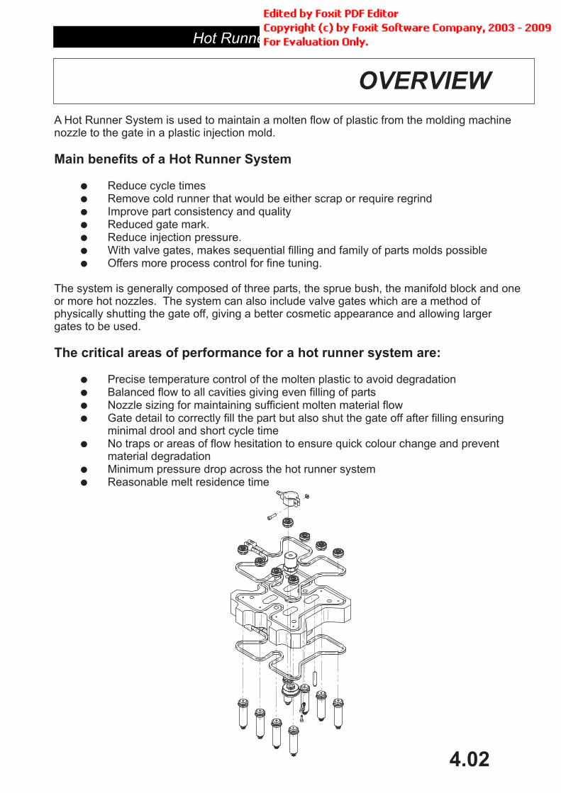
A Hot Runner System is used to maintain a molten flow of plastic from the molding machinenozzle to the gate in a plastic injection mold.
Reduce cycle timesRemove cold runner that would be either scrap or require regrindImprove part consistency and qualityReduced gate mark.Reduce injection pressure.With valve gates, makes sequential filling and family of parts molds possibleOffers more process control for fine tuning.
The system is generally composed of three parts, the sprue bush, the manifold block and oneor more hot nozzles. The system can also include valve gates which are a method ofphysically shutting the gate off, giving a better cosmetic appearance and allowing largergates to be used.
Precise temperature control of the molten plastic to avoid degradationBalanced flow to all cavities giving even filling of partsNozzle sizing for maintaining sufficient molten material flowGate detail to correctly fill the part but also shut the gate off after filling ensuringminimal drool and short cycle timeNo traps or areas of flow hesitation to ensure quick colour change and preventmaterial degradationMinimum pressure drop across the hot runner systemReasonable melt residence time
Main benefits of a Hot Runner System
The critical areas of performance for a hot runner system are:
�
�
�
�
�
�
�
�
�
�
�
�
�
�

Hot Runner Systems
4.03
NOZZLES

Hot Runner Systems
4.04
GATE SELECTION
When designing an injection mold the size and location of the gate is one of the most importantconsiderations for correct molding of the part. With Hot Runner molds the most common gatetype is direct gating. Direct gating offers the simplest construction and high reliability.
Mastip also makes a range of nozzles with other gate options such as Side, Edge and Valvegates, refer nozzle catalogue.
Considerations when designing the gateFlow ratePressure dropCycle time"Shut off" after filling to prevent droolingVisual impact of the gate on the component part
As well as the size of the gate the actual shape of the gate and gate cavity is of vital importanceto its performance. In particular the size of the land is important as too long a land increasesthe pressure drop, and too small a land weakens the gate.
When considering nozzle selection and gate sizing it is important to look at the two incombination.
The shot size of the part.Material to be molded
Material Flow Index (M.F.I.)AdditivesGlass fiberFlame retardant
Cosmetic appearance of the gatePart wall thicknessLongest flow length of the partRequired cycle time
There are three broad categories of materials, easy, medium and difficult to mold materials.
When selecting nozzles for plastics with large percentages of filler ( >15% ) or a very low M.F.I.the material effectively moves up a grade i.e. Easy to Medium or Medium to Difficult.
Parts with very thin wall sections or very long flow lengths will need a larger than normal nozzleand gate to achieve proper filling, this may be one to two sizes.
As a general rule the gate should be a of 75% of the wall section at the injection point for amedium flow materials. This is can be adjusted up or down for easy or difficult materials.
Direct Gating
Factors to consider:
Material Category
�
�
�
�
�
�
�
�
�
�
�
�
�
�
�
Hot Runner Systems
4.05
GATE DETAILS
Design Stage
uniform�
�
�
�
�
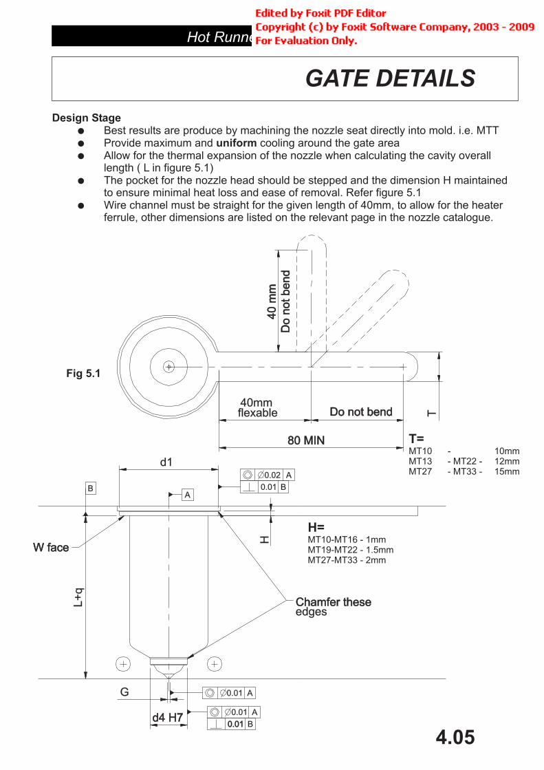
Best results are produce by machining the nozzle seat directly into mold. i.e. MTTProvide maximum and cooling around the gate areaAllow for the thermal expansion of the nozzle when calculating the cavity overalllength ( L in figure 5.1)The pocket for the nozzle head should be stepped and the dimension H maintainedto ensure minimal heat loss and ease of removal. Refer figure 5.1Wire channel must be straight for the given length of 40mm, to allow for the heaterferrule, other dimensions are listed on the relevant page in the nozzle catalogue.
T=MT10 - 10mmMT13 - MT22 - 12mmMT27 - MT33 - 15mm
H=MT10-MT16 - 1mmMT19-MT22 - 1.5mmMT27-MT33 - 2mm
Fig 5.1
L+
q
d1
H
d4 H7d4 H7
W faceW face
AB
0.01 A
0.010.01 B
0.02 A
0.01 B
G 0.01 A
T80 MIN80 MIN
40
mm
40
mm
Do
no
tb
en
dD
on
ot
be
nd
Do not bendDo not bend
Chamfer theseChamfer theseedges
40mmflexable

Hot Runner Systems
4.06
GATE DETAILS
Manufacturing Stage
Retro fitting Nozzle
�
�
�
�
�
�
�
�
�
Concentricity between G and d4 is vitalPerpendicularity between d4 and W is also vitalConcentricity between d1 and d4 is importantSizing of d4 is important to prevent leaksChamfer points indicated to aid fitting of the nozzleMachining the gate area produces better results than sparking (EDM).
It is possible to retro fit the new MT series nozzle into the older SB series cavitieswith some minor modifications (figure 5.2) See pages 1.2.5-1.2.6 in nozzle cataloguefor details.Requires special retro nutMay require a spacer in the seat area
Remove material fromstandard Sb gate profile
Conversion machiningdetail for Sb to MTT
Fig 6.1

Hot Runner Systems
4.07
GATE MODIFICATIONS
Sometimes it is desirable to enlarge the recommended gate on a nozzle to increase theflow of plastic melt for a given nozzle size.
It should be noted that flow increases exponentially with the increase in gate diameter. Hence gate sizeshould be adjusted in small increments.
MASTIP does not recommend increasing the G dimension more that 50% above the size shown in thenozzle catalogue.If larger gate is required, a larger nozzle should be considered.
(dimension. G)
The type of plastic to be molded
The viscosity (MFI) of the melt.
The thickness of the wall section to be injected into.
The amount of cooling around the gate. (Note: gate cooling is a complex variable and cycletime, gate profile and land length are also involved)
The maximum possible size for the gate is dependent on a number of variables:
�
�
�
�
Ga
tesiz
e
Material
CrystallineAmorphous
Ga
tesiz
e
Viscosity (MFI)
HighLow
Ga
tesiz
e
Part wall thickness
ThickThinG
ate
siz
eGate cooling
HotCold
It is VITAL to maintain q at a maximum of 0.2mm for proper nozzle function.(see figure 7.1)When the gate dimension G is enlarged the gate profile must be changed to maintain the correct land (q)If the taper angle in the gate is not lowered (shown with dotted line) the q dimension or land lengthincreases to q+.
Increase the heating effect around the gate (possibly burning the materiel)
Restrict flow
Cause the gate to freeze off prematurely especially when running chilled water around thegate
Leave an enlarged gate vestige (mark)
Contact MASTIP if you require specific details for your application.
This increase in land length will:
�
�
�
�
Fig 7.1
G
G MOD.
q q+

Hot Runner Systems
4.08
GATE MODIFICATIONS BUSH NUT
Figure 8.1 shows the best way to correct the land length (q) after an increase in gate size (G) in a bushnut. The modification is best done with a cutter and not EDM, as EDM can cause the gate to crack.Check the land length with plastercine. Contact if you require specific details for yourapplication.
MASTIP
Figure 8.2 shows another method to correct the land length when G is changed. It is not therecommended method. but machining of the nut may be easier. This method will leave a raised dome onthe part.It is also possible to machine the MOD dimension off the face of the nut, but this will require re-machineing the nozzle cavity, manifold spacers heights etc.
In some MTB and MTS applications sticking of plastic may occur to the front of the nut during operation.This is due to excessive heat build up in the nut perhaps because of inadequate gate cooling or a rapidcycle time.This problem can be corrected by using the BNE or SNE nuts.These nuts have full contact with the wall of the nozzle cavity and by machining on a rebate(H dimension) the customer can adjust the heat loss from the nut to suit. (Figure 8.3)
Fig 8.1
Fig 8.2
Fig 8.3
G
G MOD.
q q+
MO
D..
G
G MOD.
q
H
H-2
H- 4
Hot Runner Systems
4.09
GATE MODIFICATIONS SPRUE NUT
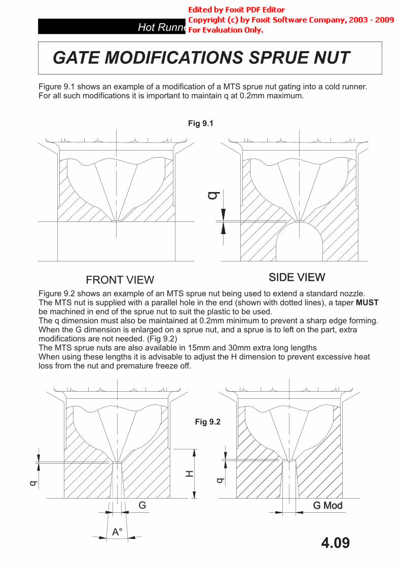
Figure 9.1 shows an example of a modification of a MTS sprue nut gating into a cold runner.For all such modifications it is important to maintain q at 0.2mm maximum.
Figure 9.2 shows an example of an MTS sprue nut being used to extend a standard nozzle.The MTS nut is supplied with a parallel hole in the end (shown with dotted lines), a taperbe machined in end of the sprue nut to suit the plastic to be used.The q dimension must also be maintained at 0.2mm minimum to prevent a sharp edge forming.When the G dimension is enlarged on a sprue nut, and a sprue is to left on the part, extramodifications are not needed. (Fig 9.2)The MTS sprue nuts are also available in 15mm and 30mm extra long lengthsWhen using these lengths it is advisable to adjust the H dimension to prevent excessive heatloss from the nut and premature freeze off.
MUST
Fig 9.1
Fig 9.2
FRONT VIEW SIDE VIEWSIDE VIEW
q
H
A°
q
G G ModG Mod
q
Hot Runner Systems
4.10
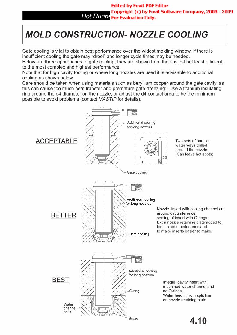
MOLD CONSTRUCTION- NOZZLE COOLING
ACCEPTABLE Two sets of parallelwater ways drilledaround the nozzle.(Can leave hot spots)
BETTER
BEST
Nozzle insert with cooling channel cutaround circumferencesealing of insert with O-rings.Extra nozzle retaining plate added totool, to aid maintenance andto make inserts easier to make.
Integral cavity insert withmachined water channel andno O-rings.Water feed in from split lineon nozzle retaining plate
Gate cooling is vital to obtain best performance over the widest molding window. If there isinsufficient cooling the gate may “drool” and longer cycle times may be needed.Below are three approaches to gate cooling, they are shown from the easiest but least efficient,to the most complex and highest performance.Note that for high cavity tooling or where long nozzles are used it is advisable to additionalcooling as shown below.Care should be taken when using materials such as beryllium copper around the gate cavity, asthis can cause too much heat transfer and premature gate “freezing”. Use a titanium insulatingring around the d4 diameter on the nozzle, or adjust the d4 contact area to be the minimumpossible to avoid problems (contact for details).MASTIP
Additional cooling
for long nozzles
Gate cooling
Braze
Waterchannelhelix
O-ring
Additional coolingfor long nozzles
���������� �������� ��� ����� �
��� ������

Hot Runner Systems
4.11
INSTALLATION
When installing a Nozzle please note the followingMASTIP
�
�
�
�
�
�
�
�
�
Nozzles should be handled carefullyAvoid scratching or denting the ground facesClean of anti rust oil with solvent
Carefully enter the nozzle into the nozzle cavity and gently press inAlign the wire with the wire slot before fully installing. DO NOT try and turn the nozzleby the wires. Make sure heater and thermocouple wires are not sharply bent orcrushed when fittedFor multi nozzle molds, check that the W face on all the nozzles are the same plane(+/-0.02)Keep nozzle contact to a minimum in areas indicated in Fig 11.1Do not fit the o-rings until all the nozzles have been checked for fitting height and themanifold is ready to be assembled in the mold.When up to heat check clearance around the tip between the tip and the gate with apiece of i.e. fuse wire. Their must be clearance and it must be uniform, iftheir is no or very little clearance (less than 0.2mm) check calculations for E valueand gate size.
soft wire
� Fit nozzles one at a time and check for correct and even clearance around the tipusing "flexible putty" and for correct gate land length.
Fig 11.1
Face WFace W
O-ring (optional)O-ring (optional)
Ke
ep
co
nta
ct
toa
mim
imu
m
Ke
ep
co
nta
ct
toa
min
imu
m
Ga
p=
E+
0.2
mm Use soft wire to
check clearancearound gate.
Use soft wire tocheck clearancearound gate.

Hot Runner Systems
4.12
START UP AND RESTART
Starting and restarting a Hot Nozzle
Procedure for colour change
1. Ensure "Soft Start" is selected on the temperature controller
2. Allow 10 minutes for the nozzle to heat up
3. Purge machine barrel before connecting to nozzle
4. Slowly bring machine nozzle up to hot nozzle to avoid damage
5. When nozzle is up to temperature you are ready to inject the mold
6. Check material comes out the gate and correct if required
7. Adjust nozzle temperature to get suitable molding (Note: nozzle will often need to runhotter than barrel temperature to achieve a good result)
8. If the machine is left idle and only a single nozzle is used, (ie no manifold)it is strongly recommended to gently purge the first shot through the MASTIP nozzle.This will clear any cool slug that may have formed near the head.
1. Increase mold temperature by 15 C
2. Increase manifold and nozzle temperature by 50 C
3. Retract molding machine nozzle
4. Auto purge molding machine as per you standard practice
5. Hand purge using standard material
6. Re-start normal cycle - 6 shots
7. Lower manifold and nozzle temperature 20 C - 1 shot
8. Lower manifold and nozzle temperature 20 C - 1 shot
9. Lower manifold and nozzle temperature 10 C - 1 shot
10. Lower mold temperature 15 C
11. New colour is now ready
�
�
�
�
�
�
Hot Runner Systems
4.13
MAINTAINENCE
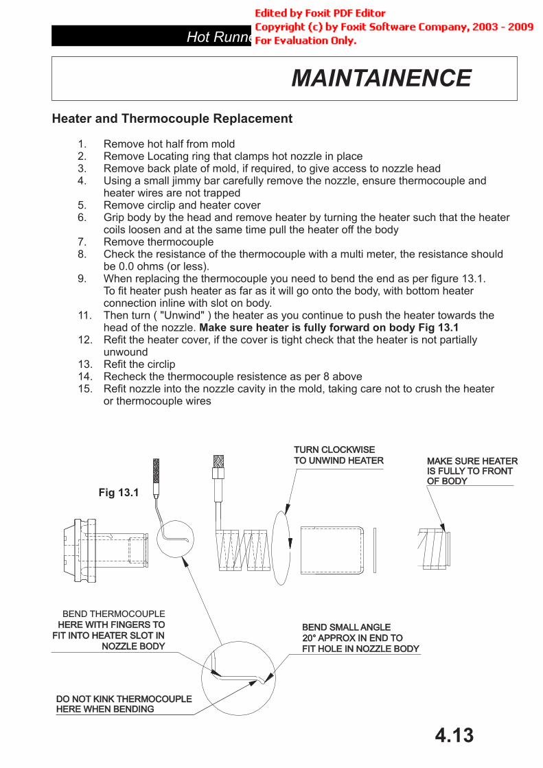
Heater and Thermocouple Replacement
1. Remove hot half from mold2. Remove Locating ring that clamps hot nozzle in place3. Remove back plate of mold, if required, to give access to nozzle head4. Using a small jimmy bar carefully remove the nozzle, ensure thermocouple and
heater wires are not trapped5. Remove circlip and heater cover6. Grip body by the head and remove heater by turning the heater such that the heater
coils loosen and at the same time pull the heater off the body7. Remove thermocouple8. Check the resistance of the thermocouple with a multi meter, the resistance should
be 0.0 ohms (or less).9. When replacing the thermocouple you need to bend the end as per figure 13.1.
To fit heater push heater as far as it will go onto the body, with bottom heaterconnection inline with slot on body.
11. Then turn ( "Unwind" ) the heater as you continue to push the heater towards thehead of the nozzle.
12. Refit the heater cover, if the cover is tight check that the heater is not partiallyunwound
13. Refit the circlip14. Recheck the thermocouple resistence as per 8 above15. Refit nozzle into the nozzle cavity in the mold, taking care not to crush the heater
or thermocouple wires
Make sure heater is fully forward on body Fig 13.1
BEND SMALL ANGLEBEND SMALL ANGLE
20° APPROX IN END TO20° APPROX IN END TO
FIT HOLE IN NOZZLE BODYFIT HOLE IN NOZZLE BODY
BEND THERMOCOUPLE
HERE WITH FINGERS TOHERE WITH FINGERS TO
FIT INTO HEATER SLOT INFIT INTO HEATER SLOT IN
NOZZLE BODYNOZZLE BODY
Fig 13.1
TURN CLOCKWISETURN CLOCKWISE
TO UNWIND HEATERTO UNWIND HEATER
DO NOT KINK THERMOCOUPLEHERE WHEN BENDINGDO NOT KINK THERMOCOUPLEHERE WHEN BENDING
MAKE SURE HEATERIS FULLY TO FRONTOF BODY
MAKE SURE HEATERIS FULLY TO FRONTOF BODY

Hot Runner Systems
4.14
MAINTENANCE
MTNOZZLES
ASSEMBLY TORQUEREQUIREMENT
LB.FT N.m10 SERIES 10 – 12 14 - 16
13 SERIES 10 – 15 14 - 20
16 SERIES 15 – 20 20 - 27
19 SERIES 20 – 25 27 - 34
22 SERIES 20 – 30 27 - 41
27 SERIES 30 – 35 41 - 48
33 SERIES 30 – 40 41 - 54
Tip Blockage
1. Very carefully try and remove the blockage with a small piece of wire, taking carenot to damage either the tip or the gate
2. If unsuccessful remove nozzle from tool.3. Remove circlip and heater cover4. Place body in three jaw chuck5. Heat the nozzle up to the plastic’s processing temperature.6. Unscrew nut7. Remove plastic from bush and tip taking care not to scratch or damage either one8. If the blockage is a foreign body, find cause and fix the problem. DO NOT
reassemble nozzle and tool until the problem is identified, as more contaminationcoming through the hot runner system will only cause more blockages
9. Reassemble nozzle making sure to use the correct torque setting when tighteningthe bush nut
10. Reassemble mold
Fig 14.1 TORQUE WRENCHTORQUE WRENCH
THREE JAW CHUCKTHREE JAW CHUCK
NOZZLE
Hot Runner Systems
4.15
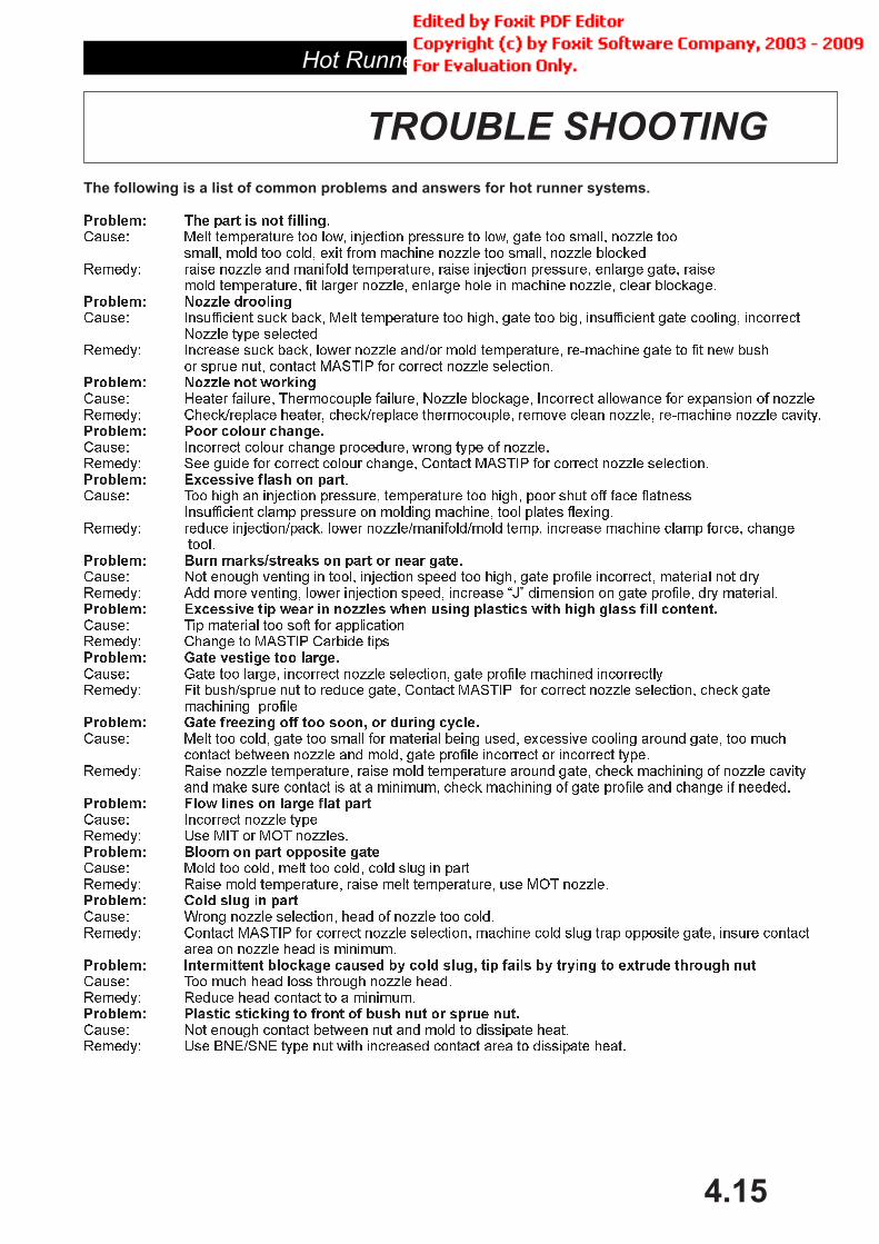
TROUBLE SHOOTING
The following is a list of common problems and answers for hot runner systems.
������ ���� ��������� ��� �� � ��������� ������� �� �� � ���� ��� ����� ������ �������� ��� ��� ����� ���� ��� ������ ������ ��� ����� ������ �������
������ ����� ������ ��� ������� ���������� ����� ��������� �������� ������� ����� �������� ���������� ��� ������ ������� ������� ���� �� ������ ������� ����� ���������
������ ������������ ���� ����� ���� ��������� ��� ����� ���� ��� ���� ������������ ���� �������� ��������������� ��� ��������
������ �������� ���� ����� �� �� ������ ��� �� ��� ���������� ��!������ ���� �� ��� �� ������ ���� ���� ������� �"#$�% ��� ������� ������ ����������
������ &����� �������� $��������� �������� ������ ��������� ��������� ���� ���� ��� �������� �� ������������ ����� ������ ������� ����� ������ ����������� ���'� ����� ������� ��!������ ������ ��'����
������ ��������� ������ ������ ��������� ���� ��� �� ������������� #�� ����� ��� ������� ������ ������� ������� �"#$�% ��� ������� ������ ����������
������� $�� ���� �� ��������� �������� ��������� ��� ����� ��� ���� ��� ���� ��������
������������ ��� ������� �� ������ ������� ���� ����� �������������� ������ ��������� ���� �� �� ������ ������� ��� ��� �������� ������ ��� ������ ������
�����
������ ��� ������ '������ �� ����� ��������� ���� ��� ����� ���� ������ ���������� ������� ��� ��������� "�� ��� '������� �� �� ��������� ����� �������� ()* �������� �� ���� ������� ��� ��������
������ $� ������� ��� ���� ��� ���������
�������� �� ��� � ��� � �� ���
�������� ������ ����� ��
�������� ������ ��� ���� ��
�������� ���� ������ ������
�������� ������ �� ���� �� ���
�������� ���� ������������� �� ��� �� ���� �����
�������� ������ �� � ���� � ������� ��� �� �� ���� �� � � � ����� � �� ��������
������ ������ �� �"#$�% ������� ����������� ���� ���� �� ��� ������
�������� ���� ����� �� ��� ��� ���� �� ��� �� �!����
�������� "��� � ��� �� ����� ���� ���
�������� ����� �� ��� ��� �� ����
�������� #��� ���� � ���
�������� $����� ����� �������� ������ �! ���� ���� � �� �� �! ��! �� �� ������� ����� ���
�������� ����� � �� �� �� �� ����� �� ��� ��� �� ���� ����
������ +��� ��� ������ ��������� ������ ���������� ���� ������ ������� ����������������� ,�� ���� ���� ��� �� ������ ����� ������� �"#$�% ��� ������� ������ ���������� ����� ����
�������� ������
������ ���� ��� ����� ���� ��� ���� ��� ������� ����� ����� �������'� ������� ������ ����� ��� ���������� ��� ��� ������ ��� ���� ���� ������ ��������� �� ��������� ����
������ ����� ������ ���������� ����� ��� ��������� ������ ����� ����� �������� �� ������ ��'������ ��� ���� ������� �� �� � ����� ����� �������� �� ���� ������ ��� ������ �� �������
������ ��������� ������ ��������� -�� ��$ �� �.$ ��������
������ ���� ��� ����� ��� ��� ����� ���� ���� �� ��������� ����� ��� ���������� ����� ��� ���������� ��� �.$ �������
������ /���� ������ ���������� ���� �� ������ ��� ����������� ������� �"#$�% ��� ������� ������ ���������� ������ ���� ���� ��� ������ ����� ������ �������
���� �� ������ ���� �� �����
������ $�� ��� ���� ���� ������� ������ ����������� ������ ���� ������� �� � �����
������ ��� ������ ������� ��� ��� ��� ��� ��� �� �������� ����������� -�� 0�1 #�1 ��� ��� ��� ��������� ������� ���� �� �������� �����

Administrator
迈时 热流道系统

Hot Runner Systems
4.16
MANIFOLDS

Hot Runner Systems
4.17
BASIC DESIGN STEPS / MANIFOLD SELECTION
If you have any questions do not hesitate to contact MASTIP.
�
�
�
�
�
�
�
�
�
�
�
�
�
�
�
�
�
�
�
�
�
�
�
�
�
Estimate weight of part and material to be used based on design specification.Identify location of gate and suitable gate type.This is dependent on:
cosmetic appearancewall sections,dimensional stability.
Identify suitable nozzle series noting above factorsColour change importanceThin walled part or long flow lengths (Increase nozzle size one or two sizes)Abrasive material (special tips, gate inserts etc)Fast cycle times needed (more gate cooling)No flow marks acceptable (MIT or MOT tip)Visible part surface must be perfect (valve gate)
Calculate number of parts moldable in tool based on:machine shot sizeclamp tonnagemachine plattern sizeminimum distance between nozzles.
Lay out the drops so that the manifold is as symmetrical as possible (fig 17.1), as per themanifold catalogue.Non-symmetrical manifolds are harder to balance and more expensive to design.Consider all variables of manifold such as:
Overall height.Heater exit, thermocouple connections, and associated wiringGate cooling and back plate coolingProvision for extra split line for maintenanceExtra height in tool if valve gating is usedAllow minimum 10mm air gap all round manifold.
Select standard manifolds with relevant dimensions and option details from catalogue, orcontact for custom design.MASTIP
MANIFOLD DESIGN GUIDELINES
L1 L2
R2
R1
L1 L2
R2
R1
Good manifold layoutAll runners equallength giving balanceddesign
length giving unbalanceddesign. Extra work is required to balance
Poor manifold layoutRunners un-equal
Sprue
Dropper
Fig 17.1

Hot Runner Systems
4.18
TOOL/MANIFOLD DESIGN FEATURES
Design guidelines for High Production /Long Life Tooling
�
�
�
�
�
�
�
�
�
Use thick nozzle cavity plate with longer nozzles for better rigidity and longevity. Make provisions for
extra water cooling in middle of plate around nozzles.
Machine manifold pocket from one piece of solid tool steel, add provision for water-cooling.
Use thick back plates (Minimum 50mm thick).
Accurately machine and assemble the nozzle seating (W face and d1 area), nozzle nut seating (d4
area) and maintain correct L and E values (see page 1.5.1)
Use insulation board between platen and back plate.
Use water cooled gate inserts with cooling right around the insert. (page 4.10)
Use extra split line to allow clearing of nozzle blockages at gate without having to strip down hot half.
Make sure wiring is not exposed to the direct heat of the manifold, use aluminum shields over the
wiring troughs if needed.
Provide adequate manifold clamping between backplate and nozzle cavity plates to ensure sealing
between manifold and nozzles, recommends three bolts per drop with a minimum of two
bolts per drop as close to manifold as possible. (see page 4.20).
MASTIP
Fig 18.1
10mm min10mm min
WATER COOLINGWATER COOLING
GATE INSERTGATE INSERT
EXTRA
SPLIT
LINE
INSULATION BOARDINSULATION BOARD
WATER
CHANNEL
50m
m
WATER
COOLING
BACKPLATE
NOZZLE
RETAINER
PLATE
CAVITY
PLATE
d1
d4
W
L+
q+
E
Hot Runner Systems
4.19
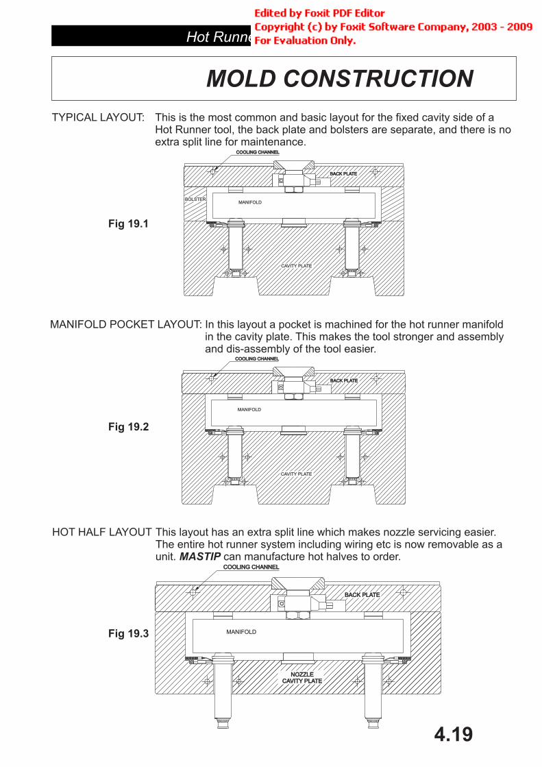
MOLD CONSTRUCTION
TYPICAL LAYOUT: This is the most common and basic layout for the fixed cavity side of aHot Runner tool, the back plate and bolsters are separate, and there is noextra split line for maintenance.
MANIFOLD POCKET LAYOUT: In this layout a pocket is machined for the hot runner manifoldin the cavity plate. This makes the tool stronger and assemblyand dis-assembly of the tool easier.
HOT HALF LAYOUT This layout has an extra split line which makes nozzle servicing easier.The entire hot runner system including wiring etc is now removable as aunit. can manufacture hot halves to order.MASTIP
COOLING CHANNELCOOLING CHANNEL
MANIFOLD
CAVITY PLATE
BACK PLATEBACK PLATE
BOLSTER
COOLING CHANNELCOOLING CHANNEL
MANIFOLD
CAVITY PLATE
BACK PLATEBACK PLATE
COOLING CHANNELCOOLING CHANNEL
MANIFOLD
NOZZLECAVITY PLATE
NOZZLECAVITY PLATE
BACK PLATEBACK PLATE
Fig 19.3
Fig 19.2
Fig 19.1
Hot Runner Systems
4.20
�
�
�
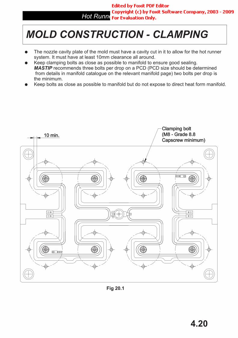
The nozzle cavity plate of the mold must have a cavity cut in it to allow for the hot runnersystem. It must have at least 10mm clearance all around.Keep clamping bolts as close as possible to manifold to ensure good sealing.
recommends three bolts per drop on a PCD (PCD size should be determinedfrom details in manifold catalogue on the relevant manifold page) two bolts per drop isthe minimum.Keep bolts as close as possible to manifold but do not expose to direct heat form manifold.
MASTIP
MOLD CONSTRUCTION - CLAMPING
10 min.10 min.
Clamping boltClamping bolt
(M8 - Grade 8.8(M8 - Grade 8.8
Capscrew minimum)Capscrew minimum)
Fig 20.1
Hot Runner Systems
4.21
MOLD CONSTRUCTION -BACK PLATE COOLING
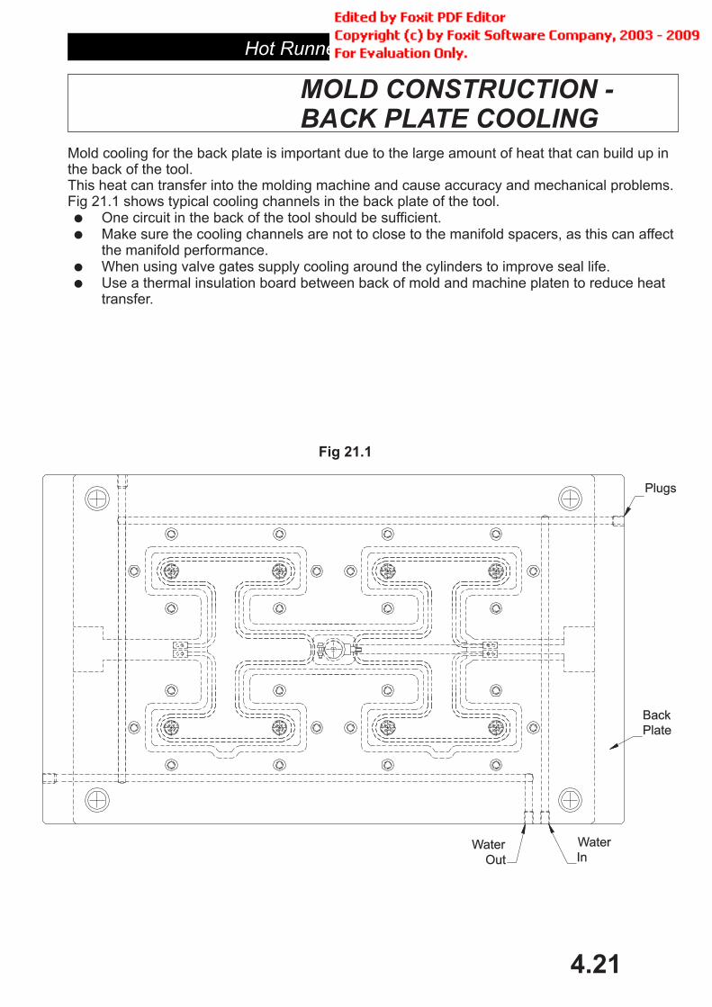
Mold cooling for the back plate is important due to the large amount of heat that can build up inthe back of the tool.This heat can transfer into the molding machine and cause accuracy and mechanical problems.Fig 21.1 shows typical cooling channels in the back plate of the tool.
One circuit in the back of the tool should be sufficient.Make sure the cooling channels are not to close to the manifold spacers, as this can affectthe manifold performance.When using valve gates supply cooling around the cylinders to improve seal life.Use a thermal insulation board between back of mold and machine platen to reduce heattransfer.
�
�
�
�
Water
InWater
Out
Plugs
Back
Plate
Fig 21.1

Hot Runner Systems
4.22
MOLD CONSTRUCTION - WIRING
Figure 22.1 shows a cutaway view of a 8 drop manifold cavity plate, to illustrate how the wiringgrooves for the nozzles are best set upKey points:1. The wiring slots for the nozzles must be of sufficient size, see nozzle catalogue.
ote the length required to accommodate the nozzle heater ferules.If there is insufficient room the heaters may be bent. See Fig 22.1
2. Where the wiring troughs meet, allow for a larger slot to accommodate the bundledmass of wires.
3. Provision should be made to clamp the wires in place, as loose wiring can come incontact with the hot manifold and be damaged by the manifold heat. See Fig 22.2
4. For maximum life and reliability, or where running temperatures for the manifold areabove 260 C an aluminum shield should be used that covers the wiring trough to protectthe wires from the heat. See Fig 22.1
5. Make sure their are no sharp edges to damage the nozzle wires, and that the wires arenot crushed.
6. Allow a cutout for mounting box7 Never rotate the nozzle by the heater or thermocouple wires
�
Especially n
4
6
Fig 22.1
Fig 22.2
5
2
1
Hot Runner Systems
4.23
INSTALLATION
Fitting nozzlesMASTIP
�
�
�
�
�
�
�
�
�
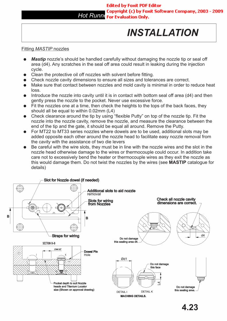
Mastip nozzle’s should be handled carefully without damaging the nozzle tip or seal offarea (d4). Any scratches in the seal off area could result in leaking during the injectioncycle.Clean the protective oil off nozzles with solvent before fitting.Check nozzle cavity dimensions to ensure all sizes and tolerances are correct.Make sure that contact between nozzles and mold cavity is minimal in order to reduce heatloss.Introduce the nozzle into cavity until it is in contact with bottom seal off area (d4) and thengently press the nozzle to the pocket. Never use excessive force.Fit the nozzles one at a time, then check the heights to the tops of the back faces, theyshould all be equal to within 0.02mm (L4)Check clearance around the tip by using “flexible Putty” on top of the nozzle tip. Fit thenozzle into the nozzle cavity, remove the nozzle, and measure the clearance between theend of the tip and the gate, it should be equal all around. Remove the Putty.For MT22 to MT33 series nozzles where dowels are to be used, additional slots may beadded around the nozzle head to facilitate easy nozzle removal fromthe cavity with the assistance of two die leversBe careful with the wire slots, they must be in line with the nozzle wires and the slot in thenozzle head otherwise damage to the wires or thermocouple could occur. In addition takecare not to excessively bend the heater or thermocouple wires as they exit the nozzle asthis would damage them. Do not twist the nozzles by the wires (see catalogue fordetails)
opposite each other
MASTIP
Dowel PinDowel PinHole
this sealing area.this sealing area.
Do not damageDo not damage
Additional slots to aid nozzleAdditional slots to aid nozzleremoval
Ø44 h744 h7
Straps for wiringStraps for wiring
Slot for Nozzle dowel (if needed)Slot for Nozzle dowel (if needed)
Slots for wiringSlots for wiringfrom Nozzlesfrom Nozzles
Pocket depth to suit NozzlePocket depth to suit Nozzle
heads and Titanium Locatorheads and Titanium Locator
size (Shown on approval drawing)size (Shown on approval drawing)
Check all nozzle cavityCheck all nozzle cavitydimensions are correct.dimensions are correct.
d4Do not damageDo not damage
this sealing area d4.this sealing area d4.
BB
I K
SECTION B-BSECTION B-B
Do not damageDo not damage
this facethis face
DETAIL I
Ød1
L4
DETAIL K
MACHING DETAILS.MACHING DETAILS.

FITTING THE MANIFOLD.
�
�
�
�
�
To ensure there is proper expansion allowance between the manifold and the mold, so the nozzleswill seal correctly follow this procedure
Measure the overall heights of manifold, the steel and titanium spacers plus L4 on the nozzle
Then measure the height of the space the manifold and nozzles will sit in. I.e. the height fromface W to the backplate.
NOTE: The height of the steel and titanium spacer will measure more than is shown on theapproval drawing because the steel spacer has a 0.3mm grinding allowance.
At operating temperature there should be 0.05mm interference between the manifold titaniumspacer and the mold back plate. This is adjusted by grinding the steel spacer.
To calculate the correct amount to grind of the spacers follow this example:
Nozzle = MTT16036 (L4=15.00mm)Manifold height = 44.00mmTitanium spacer = 6.5mmSteel spacer = 5.3mmDepth from face W to backplate = 70.50 (11.5mm +44.00mm +15.00mm)Nozzle and manifold temperature = 230 CMold temperature = 40 C
E=(15.00mm+44.00mm+11.5mm) x 0.0000132 x (230 C-40 C) = 0.2mm70.5mm + 0.05mm (interference) = 70.55mm70.55mm-0.2mm = 70.35mm
Cold height of L4+manifold block height + spacers = 70.35mmSupplied height = 15.00mm+44.00mm+5.3mm+6.5mm= 70.80mm
So grind 0.45mm off the to achieve correct height.
MASTIP
�
�
� �
70.80mm - 70.35mm =0.45mmSTEEL SPACER
Hot Runner Systems
4.24
INSTALLATION
Fig 15.1DETAIL X
Steel SpacerSteel Spacer
Titanium SpacerTitanium Spacer
Detail XDetail X
In cold stateIn cold state
L4
11.5
0
44.0
0
70.5
0
44.0
0
W

FITTING THE MANIFOLD.
�
�
�
�
�
�
�
�
�
�
�
Fit the titanium locator and dowel pin and line up manifold. Mark out and drill and tap fixing holesfor ears if needed. if hole in ear is 12mm, use M8 - Grade 8.8 bolt with hardened washer.
Make sure suitable wiring channels are provided for the nozzles, thermocouples and manifoldheaters. Wiring should be directed to a terminal box usually on the non-operator side, on the top ofthe mold, and no wires should be crushed or excessively bent. Make sure all wiring is secure withclips or an aluminum cover.
Note
Always make sure all threads have a smear of anti-seize grease to aid in disassembly. Note thatthe ears are an assembly aid , they are not intended to hold the manifold against the nozzleand so replace the spacers, so do not over tighten as this could cause bolt failure when themanifold is heated.
Use locators to maintain alignment between back plate and the nozzle cavity plate. See figurebelow.
Clean down the manifold with solvent before assembly to remove protective oils.
Bearing blue the top of the nozzle faces, fit the manifold and check all the nozzles are in fullcontact with the manifold surface.
Assemble the ‘o’ ring to the nozzles.(if used)
Tighten ear hold down bolts (if used). To allow for heat expansion always use a belleview typewasher.
Check clearance between clamp plate and sprue bush heater. Make sure their is no contact.Check that the locator ring for the mold does not have too much clearance around top of sprue,0.4mm is enough.
Wire up the manifold and heaters and thermocouples and perform the final check.(Care should betaken to prevent any fatal shock caused while wiring. This procedure should only be carried out bysomeone with correct training in electrical equipment).
Note: Moldmakers should carefully inspect all stack heights, nozzle and manifold dimensionsagainst hot runner production drawings. Contact about any questions BEFOREassembly.
only
MASTIP MASTIP
Hot Runner Systems
4.25
INSTALLATION
MIN 8 mm.MIN 8 mm.
Sprue heaterSprue heater
band
Heat insulationHeat insulation
boardAdd cooling toAdd cooling to
these platesthese plates
Sprue locatorSprue locatorØ44
Ø30.4+0.1-0.0
Add cooling toAdd cooling to
these platesthese plates
Ød1
8.00
Ød3
Ød4 H7d4 H7
L+
q+
E
10 Min.10 Min.
Ø44H7
15
.00
2m
mM
in.
Locating
Discs
Titanium LocatorTitanium Locator
Sprue BushSprue Bush
Dowel
Manifold
wiring boxwiring box
goes heregoes here
Blue of top faceBlue of top face

Hot Runner Systems
4.26
START UP & RESTART
Starting and restarting a Hot Nozzle and manifold
1. Ensure "Soft Start" is selected on the temperature controller for both.
2. Allow 20-30 minutes for the system to heat up (depending on size)
3. Purge machine barrel before connecting to manifold sprue
4. Slowly bring machine nozzle up to sprue to avoid damage
5. When system is up to temperature you are ready to inject the mold
6. Check material comes out the gate and correct if required
7. Adjust temperature to get suitable molding (Note: nozzle will often need to runhotter than barrel temperature to achieve a good result) Manifold temperature shouldremain constant.
8. If mold is left idle and needs to be restarted, raise nozzle temperatures to make gates“live” again, increase manifold temperature by a large amounts as largeincreases of temperature above the design figures can damage the sealing faces ofthe manifold and nozzle due to excessive expansion.
nozzle
do not

Hot Runner Systems
4.27
MAINTAINENCE
MANIFOLDS:
When properly installed manifolds will operate trouble free. If a problem occurs it isusually due to heater or thermocouple failure or melt contamination.
Let the tool cool downDisassemble the hot half taking care when un-torqueing, not to bow or distort manifold.Undo screws holding in the heater and remove heater.Replacement heaters come with manifold, for extra spares contact and have themanifold’s approval drawing or A---- number ready.New heater should be installed in groove with the use of a soft hammer.
. Take care when installing new heater not to bend or distort the elementas this will damage the heater.Test heater insulation then reassemble hot half.
To clean out the runners, let tool cool and disassemble.Remove end plug grub screws, (Note it may be necessary to heat manifold to loosenscrews if they are stuck).Before you can extract the end plugs you must remove the M4 grub screws which lock theend plugs in place. This is normally located on the top of the manifold, but may be at thebottom of the heater groove, in which case you will need to remove the heater as well. Youwill need to use a puller to extract the end plugs.Then heat the manifold to the BOTTOM range of its processing temperature and using ahot wire with a hook on the end, try to hook out the melt just as the outer layer of plasticmelts in the runner.If this is not successful, heat the manifold to full operating temperature and allow to soakfor 20-30 minutes and use a tight fitting rod of soft material e.g. Aluminum to push out theplastic from the runners.If the manifold has deviation plugs, contact before attempting disassembly.
Carefully refit end plugs, making sure alignment of end radii is correct, apply anti seize tothreads on set screws.Torque to figures in manifold catalogue.Refit manifold.
MASTIP
MASTIP
MASTIP
HEATER/THERMOCOUPLE FAILURE
CLEANING OUT RUNNERS
�
�
�
�
�
�
�
�
�
�
�
�
�
�
�
Do not useexcessive force
T
� Do not under any circumstances attempt to blow out hot plastic with an air gun.
ake extreme care not to scratch bores.

Hot Runner Systems
4.28
TROUBLE SHOOTING
The following is a list of common problems and answers for hot runner systems.
������ $��������� �� ������ ���������� �� ������� ������ �� �������� ������ ����� �� ����� �� �������������� ����� ���������� �� ����� ��� ��������� ���������� ����� ������ ��������
������ .�� ������ ������� �� ����� �� ������ ������������ ������� ��� ��� ��� ��� ������� ���'�������� ���������� �� �����
������ ����� ���� �������� �������� ��� �� �� 23 �� �� ��� ���������� ������ "�� ���������� ����� ������ ���� �� ������ ������� ��� �� ��������� ����� �����������
�������� %�� ���� � �� ��� ���� � �� �����������
�������� %�� ���� ���� �� ��� �
�������� %�� ���� ���������� ��� ������
�������� %���� ������ ��� �� � ����
�������� %�� ���� ����� ���� ������ �����
�������� %�� ���� ����� ���� ��� �� �� ���
������ $��������� �� ����������� ����� ����������
������ 4����� ��� ������ ���� � ������ ��� ������ ������������� ����� ���� ��� ���� ������� ��� ����� ������ ���� � ����� ������ ��� ������������
������ ��������� ���� ���� ��� ��������� ��������� �������� �� / ���� ������� ������������� ��������������� ��� ����� ������� ��� �� '��� ���� ��������� ��� ����� ���� .!���� ������������ ������
������ ������� ������������ ��� �������� ����� ��� ������� / ���� �������� ������ ��������� ����� �������� ��� ������ ������ �� ������� ����� ������ .!������
������ �� ����� ������������ ,�� �����


Hot Runner Systems
4.29
VALVE GATES
Hot Runner Systems
4.30
GATE DETAILS
Why use a valve gate?
Gate details for MASTIP valve gate systems.
Advantages of using a valve gate
Less pressure to fill part due to larger gate size.Part will fill faster, and so cNo protruding gate mark or vestigeNo possibility of gate droolNo cold slug from thermal gateControl of gate shut off determined by molder, not by gate design or cooling etcSequential or independent control of multiple gates is possibleInsensitivity to changes in materials
Dis-advantages
CostExtra height and size in toolingExtra complexity due to actuators and control systemsPin will leave small ring in partPlastic can stick to larger pins, marking part
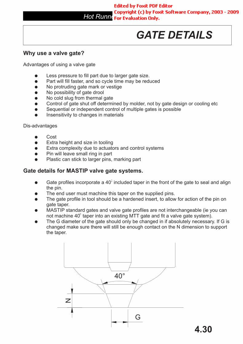
Gate profiles incorporate a 40 included taper in the front of the gate to seal and alignthe pin.The end user must machine this taper on the supplied pins.The gate profile in tool should be a hardened insert, to allow for action of the pin ongate taper.MASTIP standard gates and valve gate profiles are not interchangeable (ie you cannot machine 40 taper into an existing MTT gate and fit a valve gate system).The G diameter of the gate should only be changed in if absolutely necessary. If G ischanged make sure there will still be enough contact on the N dimension to supportthe taper.
�
�
�
�
�
�
�
�
�
�
�
�
�
�
�
�
�
�
�
�
ycle time may be reduced
40°
N
G

Hot Runner Systems
4.31
Where valve gateing is required there are several extra variables to consider.
Extra thickness must be allowed in the back plate for mounting the actuators.Allowance must be made for pneumatic / hydraulic feeds to actuators.(fittings, piping, etc)Distance between nozzles must be sufficient to allow mounting of cylinders and backplatesCooling should be provided in backplate to reduce cylinder temperatures and prolong thelife of the seals.For very large manifolds it may be necessary to mount the cylinder(s) on columns directonto the manifold, due to large thermal expansions (Contact for details)
For specific details see pages in Nozzle catalogue.
�
�
�
�
�
MASTIP
Allow for space betweenAllow for space between
other nozzles or sprueother nozzles or sprue
Provide cooling forProvide cooling foractuators
Maintain clearanceMaintain clearanceto prevent transmisionto prevent transmision
of heat into cylindersof heat into cylinders
Allow for connectorAllow for connectorfittings
MOLD CONSTRUCTION
Hot Runner Systems
4.32
INSTALLATION
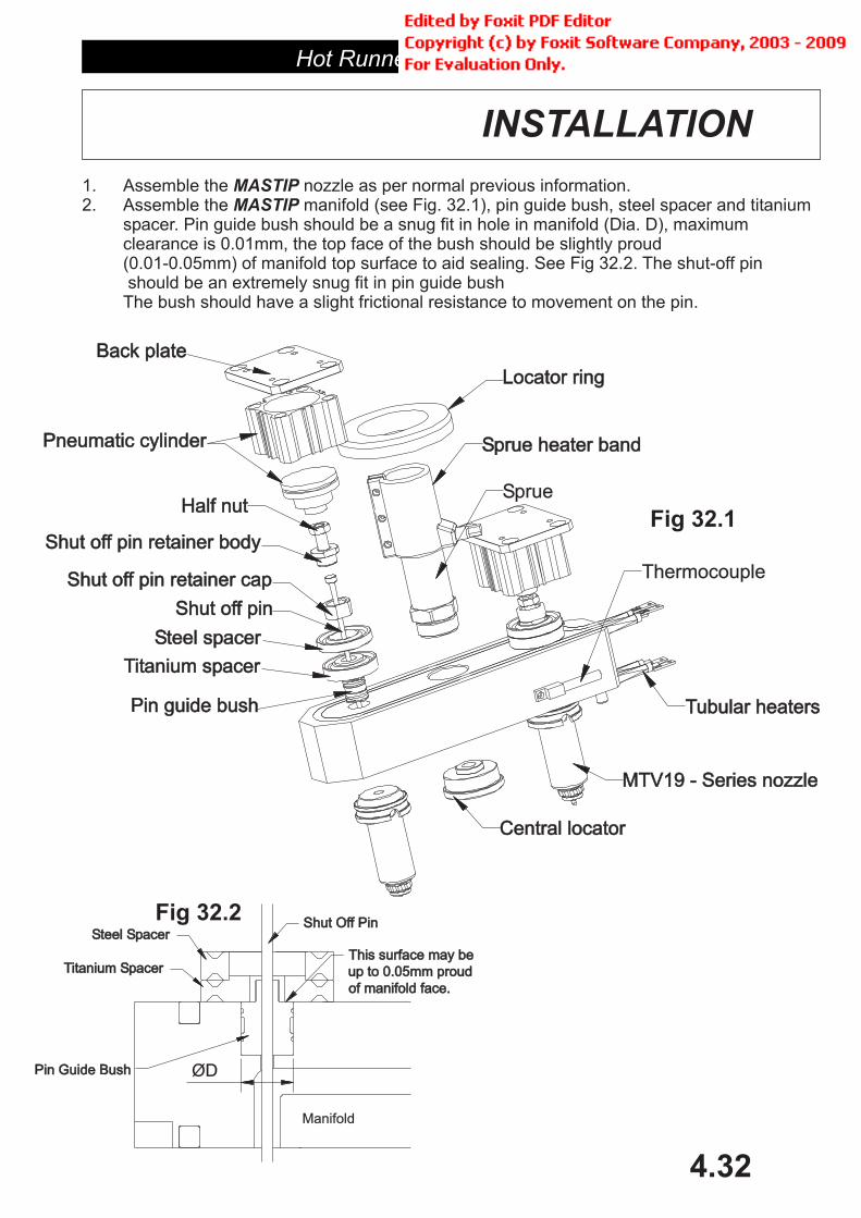
1. Assemble the nozzle as per normal previous information.2. Assemble the manifold (see Fig. 32.1), pin guide bush, steel spacer and titanium
spacer. Pin guide bush should be a snug fit in hole in manifold (Dia. D), maximumclearance is 0.01mm, the top face of the bush should be slightly proud(0.01-0.05mm) of manifold top surface to aid sealing. See Fig 32.2. The shut-off pinshould be an extremely snug fit in pin guide bushThe bush should have a slight frictional resistance to movement on the pin.
MASTIPMASTIP
Fig 32.1
Fig 32.2
Locator ringLocator ring
Sprue heater bandSprue heater band
Thermocouple
Tubular heatersTubular heaters
Sprue
Central locatorCentral locator
MTV19 - Series nozzleMTV19 - Series nozzle
Back plateBack plate
Pneumatic cylinderPneumatic cylinder
Half nutHalf nut
Titanium spacerTitanium spacer
Steel spacerSteel spacer
Shut off pinShut off pin
Pin guide bushPin guide bush
Shut off pin retainer bodyShut off pin retainer body
Shut off pin retainer capShut off pin retainer cap
Shut Off PinShut Off PinSteel SpacerSteel Spacer
Titanium SpacerTitanium Spacer
Manifold
ØDPin Guide BushPin Guide Bush
This surface may beThis surface may be
up to 0.05mm proudup to 0.05mm proud
of manifold face.of manifold face.

Hot Runner Systems
4.33
INSTALLATION
3.
Measure the distance from face W to the underside of the back plate.Measure and compare this to the stack height of the manifold and spacers and L4 dimensionof the nozzle.There should be 0.05mm of interference between the titanium spacer and the backplate at fullworking temperature.
Example
Spacer stack = 15.00mm (titanium spacer = 6.5mm, steel spacer = 8.5mm)Manifold = 44.00mmL4 of nozzle = 15.00 mmGap from face W to back plate = 74.00mmNozzle manifold operating temp = 260 CMold temperature = 60 C
E for Spacers, manifold and L4 = (15.00+44.00+15.00)x0.0000132x(260 C-60 C)= 0.2mm
Manifold, spacers etc will expand to 74.2mm in hot stateSo to achieve 0.05mm interference cold height of manifold etc will need to be 73.85mm(73.85+0.20 =74.05mm)
74.05mm-74.00mm (gap from face W to backplate) = 0.05 interference.Grind 0.15mm off the spacer
Moldmakers should carefully inspect all stack height and pocket dimensions against thehot runner drawings. Any questions should be discussed immediately with thenearest hot runner systems representative.
A cold clearance is necessary to protect the manifold components from collapsing due to thermalexpansion when the system is at operating temperature.A procedure very similar to that used on page 4.23-4.25 is used to calculate this.
�
�
� �
STEEL
MastipMastip
Fig 33.174.0
0
Cold
Clearance hereClearance here
Nozzle GateNozzle Gatepart linepart line
44.0
015.0
015.0
0
Overa
llpin
length
Overa
llpin
length
L+
E
Hot Runner Systems
4.34
INSTALLATION
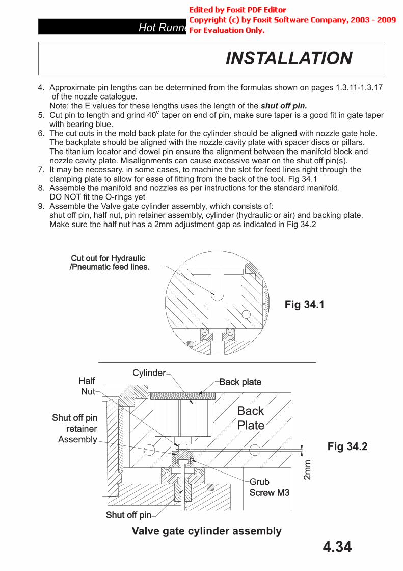
4. Approximate pin lengths can be determined from the formulas shown on pages 1.3.11-1.3.17of the nozzle catalogue.Note: the E values for these lengths uses the length of the
5. Cut pin to length and grind 40 taper on end of pin, make sure taper is a good fit in gate taperwith bearing blue.
6. The cut outs in the mold back plate for the cylinder should be aligned with nozzle gate hole.The backplate should be aligned with the nozzle cavity plate with spacer discs or pillars.The titanium locator and dowel pin ensure the alignment between the manifold block andnozzle cavity plate. Misalignments can cause excessive wear on the shut off pin(s).
7. It may be necessary, in some cases, to machine the slot for feed lines right through theclamping plate to allow for ease of fitting from the back of the tool. Fig 34.1
8. Assemble the manifold and nozzles as per instructions for the standard manifold.DO NOT fit the O-rings yet
9. Assemble the Valve gate cylinder assembly, which consists of:shut off pin, half nut, pin retainer assembly, cylinder (hydraulic or air) and backing plate.Make sure the half nut has a 2mm adjustment gap as indicated in Fig 34.2
shut off pin.�
Fig 34.2
Valve gate cylinder assembly
Fig 34.1
Back plateBack plateCylinder
Shut off pinShut off pin
Shut off pinShut off pin
retainer
Assembly
2m
m
Grub
Screw M3Screw M3
Back
Plate
Half
Nut
Cut out for HydraulicCut out for Hydraulic/Pneumatic feed lines./Pneumatic feed lines.

Hot Runner Systems
4.35
INSTALLATION
15. Now dis-assemble valve gate cylinder assembly from tool and remove backplate.Fit O rings and re-assemble
16. Before you install the valve gate cylinder assembly within the tool, fit the hydraulic pipingor air lines to the cylinder.
17. For hydraulic’s, we recommend the use of quick connect fittings with shut-off’sto prevent hydraulic fluid losses when the mold is disconnected from the hydraulic powersource.Always use solid piping whenever possible, but if in doubt seek expert advice.Care should be taken to check the maximum operating pressures and temperatures inthe tool prior to trial to ensure unit will not be damaged.The hydraulic cylinders should not be used with more than 50 bar of pressure toavoid possible damage to gate if the tool is over heated
10. Assemble the back plate on the tool.11. Place tool in position so the valve gate cylinder assembly (see 8.) can be fitted
into the back of the tool, and the front face of the gate is visible as well.12. Insert valve gate assembly into back of tool so the valve gate assembly back
plate is properly located, screw down valve cylinder back plate.13. Apply LOW pressure air to cylinder to bring cylinders forward and the measure the
gap at front of gate to the front face of pin (fig 35.1) with a depth micrometer(you may need a special anvil for the small pins). The gap should be equal to theshut off pins E value, if not remove valve cylinder assembly and adjust pin retainerand half nut until correct
14. The gap between the gate and the pin in cold state is critical. If there is tomuch gap there will be a poor gate vestige and perhaps drooling from the nozzle.If the gap is to small the pin can strike the gate and will damage it.
Fig 35.1
Adjust Pin length withAdjust Pin length with
Shut Off Pin retainerShut Off Pin retainer
and Half Nutand Half Nut
Egap
Egap
When
cold
When
cold

Hot Runner Systems
4.36
MAINTENANCE
The MASTIP valve gate system should give trouble free operation provided a few simplemaintenance is procedures are followed
Make sure pneumatic air is clean and free from water or oil.Make sure hydraulic fluid properly filtered and change regularlyMinimum air pressure should be 6 bar.Maximum hydraulic pressure should be 50 barBreak down tool and inspect for the following, every six to twelve months depending ofuse:
Service cylinders (contact for seal kits)Inspect shut off pins and shut off pin bush for wear and possible leakage
�
�
�
�
�
�
�
at cylinder
MASTIP
Hot Runner Systems
4.37
TROUBLE SHOOTING
The following is a list of common problems and answers for hot runner systems.
������ �� ��� ��� ��� �� ��������� �������� ������� ��� ������ ������� �� ����������� ����� ������ ������� ���� ��� � ��� ����� ��� ��������� ���� ������ ���������� $�� ���
����� �� ���� ���� ���������'� �������� �� '��'��
������ "������� �� ��������� ������� ��� ������ ���������� $�� ��� ���� �� ��������������� ����� ���������� ���� ��� ������� ������ ��������
�������� #!� ����� �� ��� ����
�������� #!� ����� �� ���
�������� #!� ����� &�� ��� ��
�������� %��� ����� ���� ������ ��� ��� � ���
�������� %��� ����� ���� ������� ��� ��� �
�� � �� �
�������� %��� �� ��� �� ����� �� �
�������� � � ���� ��� ��� ��� �� ��� ��� � ������� �� �� %�'� �� %('�
������ "������� �� ��������� ������� ��� ������ ���������� $�� ��� ���� �� ���������#����� ������� �� ���� �� �� ��������
������ ����� ���������� ���� ��� ������� ������ ��������� ��!����� ������
������ 0��� �� ����� �� ������������� ����� �������� �� ���� ��� ������� ����� ����� ������ �� ���� ��� ������� �����
������ /���� �,� �� ��� �� ����� ������� �� ���������� ����� ��������� �� ������ ������ �� ��� ���� ����� ��� �,��
������ ���� ��������
������ $� ��� ���� �� �������� ������ ������ ��� ���� ���������� �������� ������� ���
������ ������ �������� �� ��������� ��������� �� ��� ���� �� ��������� 1 �������������� "����� �� ������� ��� �� �������� ��� ���� ���

Administrator
迈时 热流道系统

Hot Runner Systems
4.38
MULTI-TIPNOZZLES
Hot Runner Systems
4.39
Tip assembly
Soft jawsChuck
MSM body
MSM TIP ASSEMBLY INSTRUCTIONS
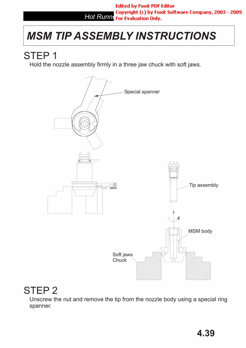
STEP 1Hold the nozzle assembly firmly in a three jaw chuck with soft jaws.
STEP 2Unscrew the nut and remove the tip from the nozzle body using a special ringspanner.
Special spanner

Hot Runner Systems
4.40
MSM TIP ASSEMBLY INSTRUCTIONS
STEP 31. Firmly hold the tip assembly with a three jaw chuck with soft jaws.2. Remove the key from the tip assembly.3. Carefully remove the collet halves from the tip assembly
STEP 41. Replace tip with new MSM tip.2. Assemble unit in reverse order, take care to align the key in the nozzle body.
Key
Circular collet ring2 pieces.
Chuckjaws soft
Open nutTip body
MSM body
Collet ring
Open nut
Tip assembly

Administrator
迈时 热流道系统

Hot Runner Systems
4.41
TEMPERATURECONTROLLERS
Hot Runner Systems
4.42
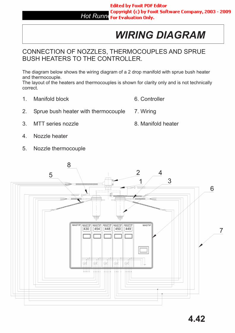
CONNECTION OF NOZZLES, THERMOCOUPLES AND SPRUEBUSH HEATERS TO THE CONTROLLER.
The diagram below shows the wiring diagram of a 2 drop manifold with sprue bush heaterand thermocouple.The layout of the heaters and thermocouples is shown for clarity only and is not technicallycorrect.
1. Manifold block 6. Controller
2. Sprue bush heater with thermocouple 7. Wiring
3. MTT series nozzle 8. Manifold heater
4. Nozzle heater
5. Nozzle thermocouple
WIRING DIAGRAM
430 454 448 450 449
6
7
5 2
1
84
3
MASTIP MASTIP MASTIP MASTIPMASTIPMASTIP MASTIP
Hot Runner Systems
4.43
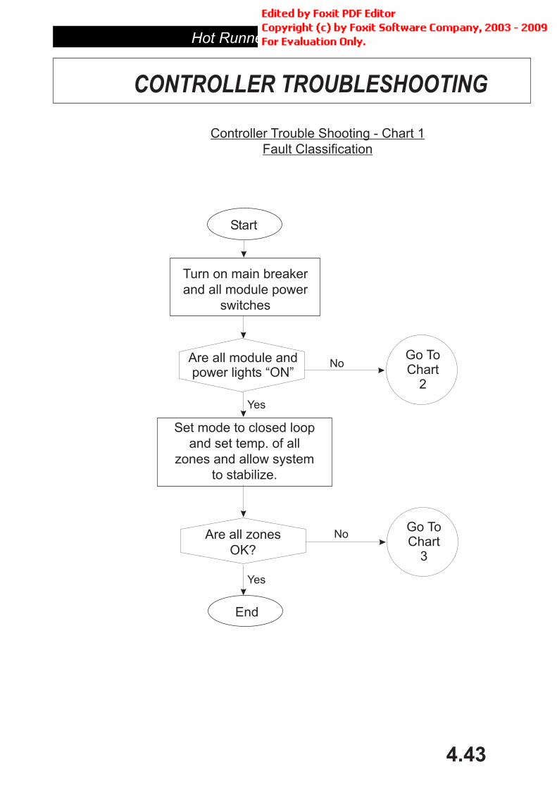
Fault Classification
Controller Trouble Shooting - Chart 1
switches
and all module power
Turn on main breaker
to stabilize.
zones and allow system
and set temp. of all
Set mode to closed loop
Start
End
Are all module andpower lights “ON”
OK?
Are all zonesGo ToChart
3
Go ToChart
2
No
Yes
No
Yes
CONTROLLER TROUBLESHOOTING
Hot Runner Systems
4.44
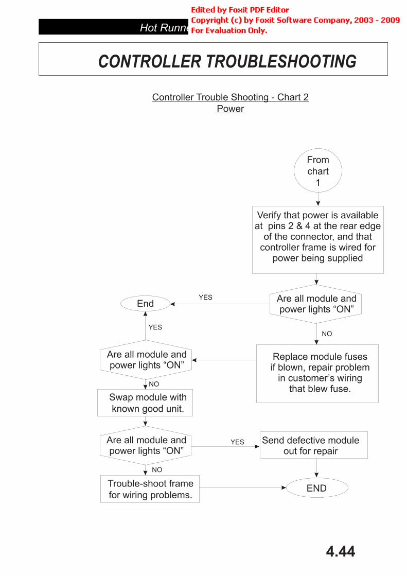
Power
Controller Trouble Shooting - Chart 2
for wiring problems.
Trouble-shoot frame
known good unit.
Swap module with
End
Verify that power is availableat pins 2 & 4 at the rear edge
of the connector, and thatcontroller frame is wired for
power being supplied
Replace module fusesif blown, repair problem
in customer’s wiringthat blew fuse.
Send defective moduleout for repair
END
YES
NO
YES
NO
YES
NO
CONTROLLER TROUBLESHOOTING
1
chart
From
Are all module andpower lights “ON”
Are all module andpower lights “ON”
Are all module andpower lights “ON”
Hot Runner Systems
4.45
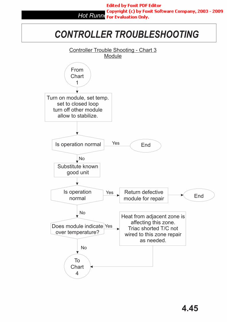
Controller Trouble Shooting - Chart 3Module
4
Chart
To
Does module indicateover temperature?
normal
Is operation
Substitute knowngood unit
Is operation normal
Turn on module, set temp.set to closed loop
turn off other moduleallow to stabilize.
1
Chart
From
Heat from adjacent zone isaffecting this zone.
Triac shorted T/C notwired to this zone repair
as needed.
module for repair
Return defectiveEnd
EndYes
No
Yes
No
No
Yes
CONTROLLER TROUBLESHOOTING

Hot Runner Systems
4.46
Controller Trouble Shooting - Chart 4Module (cont)
5
Chart
To
Does module indicateno heat?
Does module indicateunder temperature?
3
Chart
From
Does module indicateT/C reversed?
Does module indicateT/C open?
Check T/C and wiringrepair and replace
Heaters too small or burned out.Heaters not connected.
T/C not wired to this zone,shorted, or defective -
repair as needed.
Correct T/C wiring
Heaters not connectedto this zone. Heaters
too small or burned out.T/C too far from heaters.
rock power switch to resetcontroller - intermittent electrical
conditions can cause this indication.
Yes
No
Yes
No
Yes
No
Yes
No
CONTROLLER TROUBLESHOOTING
Hot Runner Systems
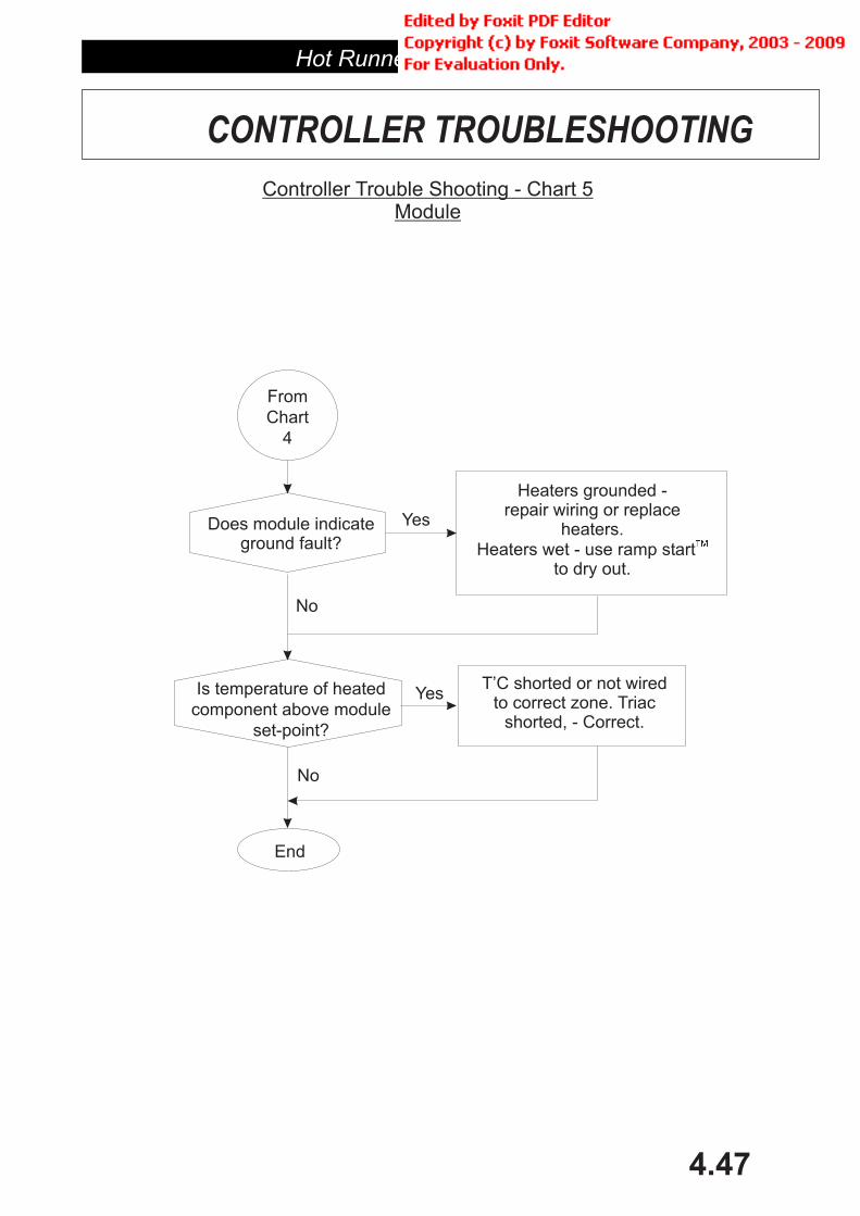
4.47
Controller Trouble Shooting - Chart 5Module
set-point?
component above module
Is temperature of heated
Does module indicateground fault?
4
Chart
From
Heaters grounded -repair wiring or replace
heaters.Heaters wet - use ramp start
to dry out.
��
T’C shorted or not wiredto correct zone. Triac
shorted, - Correct.
End
CONTROLLER TROUBLESHOOTING
Yes
No
No
Yes
Related Documents