
Welcome message from author
This document is posted to help you gain knowledge. Please leave a comment to let me know what you think about it! Share it to your friends and learn new things together.
Transcript


© 2016 SCHNEID GesmbH
All rights reserved. This document is provided by SCHNEID GesmbH.
SCHNEID GesmbH reserves the right to revise this document and to make changes from time to time in the content hereof without obligation to notify any person or persons of such revisions or changes
SCHNEID GesmbH makes no warranties on the accuracy and correctness of the information.SCHNEID GesmbH accepts no liability or responsibility for any errors or omissions in the content of the documentation.
All information, that can be taken out of this documentation, are supplied without any express, implied or tacit guarantee.
Table of contents
Table of contents
1 Safty notes................................................................................................................................8
2 Specifications...........................................................................................................................9
3 Terminal assignment / electrical connection.......................................................................10
4 Short-description of features................................................................................................12
5 Assignment of keys...............................................................................................................13
6 Instantaneous values menu..................................................................................................14
6.1 Operation values...............................................................................................................14
6.2 In-/Outputs........................................................................................................................14
6.3 Fault messages................................................................................................................14
6.4 Fault journal......................................................................................................................14
7 Settings menu........................................................................................................................15
7.1 General settings................................................................................................................15
P1 – Language/Sprache ..................................................................................................... 15 P2 – room temperature during enhancement .................................................................... 15 P3 - room temperature outside enhancement .................................................................... 15 P4 – minimum supply air temperature ................................................................................ 15 P5 – maximum supply air temperature ............................................................................... 15
7.2 Supply air fan....................................................................................................................16
P11 – minimum speed supply air ........................................................................................ 16 P12 – maximum speed supply air ...................................................................................... 16 P13 – fixed speed supply air .............................................................................................. 16 P15 – differential pressure 1 - 2point curve ........................................................................ 16 P16 – differential pressure 2 - 2point curve ........................................................................ 16
7.3 Exhaust air fan..................................................................................................................17
P21 – minimum speed exhaust air ..................................................................................... 17 P22 – maximum speed exhaust air .................................................................................... 17 P23 – fixed speed exhaust air ............................................................................................ 17 P25 – differential pressure 1 - 2point curve ........................................................................ 17 P26 – differential pressure 2 - 2point curve ........................................................................ 17
7.4 Heating coil.......................................................................................................................18
P31 – minimum return heatregister .................................................................................... 18 P32 – cut off timer heatregister .......................................................................................... 18 P33 – hysteresis temperature-request heatregister ............................................................ 18 P35 – heatregister controls supply air temp. ...................................................................... 18
7.5 Cooling coil.......................................................................................................................18
P41 – maximum return cooling register .............................................................................. 18 P42 – cut off timer cooling register ..................................................................................... 18 P43 – hysteresis temperature-request cooling register ...................................................... 18 P45 – coolregister controls supply air temp. ....................................................................... 18
7.6 Recuperation heat exchanger...........................................................................................19
P51 – minimum recuperation ratio ...................................................................................... 19
Page 4 © 2016
Table of contents
P52 – frost protective temp recuperator ............................................................................. 19 P53 – frost protective temp reference ............................................................................... 19
7.7 Bypass air flap..................................................................................................................19
P56 – minimum outside air ratio ......................................................................................... 19 P57 – bypass air flap controlled to air quality ..................................................................... 19
7.8 Ventilating times................................................................................................................20
Ventilating times ................................................................................................................ 20
7.9 Enhancement times..........................................................................................................20
Enhancement times ........................................................................................................... 20
8 Software update (manually)..................................................................................................21
9 Start-up settings....................................................................................................................22
10 Internal Menu – all parameters...........................................................................................23
10.1 Test-Display....................................................................................................................24
10.2 Output test......................................................................................................................24
10.3 Set date & time...............................................................................................................24
10.4 System settings..............................................................................................................25
P68 - SIP number ............................................................................................................... 25 P72 - send data to SinVis? ................................................................................................. 25 P73 - heat meter type ......................................................................................................... 25 P74 - number of MBus devices .......................................................................................... 25 P75 – FSS address ............................................................................................................ 25 P76 – FSS baudrate ........................................................................................................... 25 P77 – MBus baudrate ......................................................................................................... 26 P78 – SubCom address ..................................................................................................... 26 P79 – SubCom baudrate .................................................................................................... 26 P80 – Default set ................................................................................................................ 26 P81 – common fault 1 byte 1 ............................................................................................. 26 P82 – common fault 1 byte 2 ............................................................................................. 26 P83 – common fault 1 byte 3 ............................................................................................. 26 P84 – common fault 1 byte 4 ............................................................................................. 26 P85 – common fault 2 byte 1 ............................................................................................. 26 P86 – common fault 2 byte 2 ............................................................................................. 26 P87 – common fault 2 byte 3 ............................................................................................. 26 P88 – common fault 2 byte 4 ............................................................................................. 26 P89 – common fault 3 byte 1 ............................................................................................. 26 P90 – common fault 3 byte 2 ............................................................................................. 26 P91 – common fault 3 byte 3 ............................................................................................. 26 P92 – common fault 4 byte 4 .............................................................................................. 26 P97 – manual common fault ............................................................................................... 29 P98 – max impulse 3 point valves ...................................................................................... 29 P247 – load settings from MMC ......................................................................................... 29 P248 – save settings to MMC ............................................................................................. 29 P249 – MBus configuration impulse-reading ...................................................................... 29 P250 – MBus reading interval ............................................................................................ 29
10.5 Expert settings................................................................................................................30
P10 - supply air fan existing? ............................................................................................. 30 P20 - exhaust air fan existing? .......................................................................................... 30 P13 - supplyspeed controls? .............................................................................................. 30
© 2016 Page 5

Table of contents
P23 - exhaustspeed controls? ........................................................................................... 30 P120 - supply fan I-factor ................................................................................................... 30 P121 - supply fan P-region ................................................................................................ 30 P130 - exhaust fan I-factor ................................................................................................ 30 P131 - exhaust fan P-region .............................................................................................. 30 P122 - supply fan CO² point 1 ............................................................................................ 30 P123 - supply fan CO² point 2 ........................................................................................... 30 P132 - exhaust fan CO² point 1 ........................................................................................ 30 P133 - exhaust fan CO² point 2 ........................................................................................ 30 P126 – supply fan room-diff. pt.1 ....................................................................................... 31 P127 - supply fan room-diff. pt.2 ....................................................................................... 31 P136 - exhaust fan room-diff. pt.1 .................................................................................... 31 P137 - exhaust fan room-diff. pt.2 ..................................................................................... 31 P104 - filter protection supply fan? ..................................................................................... 31 P107 - filter protection exhaust fan? .................................................................................. 31 P105 - analogue/digital filter protection supply fan ............................................................. 31 P108 - analogue/digital filter protection exhaust fan .......................................................... 31 P106 - max. pressure supply air filter protection ............................................................... 31 P109 - max. pressure exhaust air filter protection ............................................................. 31 P124 – belt protection supply fan? ..................................................................................... 31 P134– belt protection exhaust fan? .................................................................................. 31 P125 - min. pressure supply air filter protection ................................................................. 32 P135 - max. pressure exhaust air filter protection ............................................................. 32 P30 - heating register existing? .......................................................................................... 33 P40 - cooling register existing? ......................................................................................... 33 P50 - recuperation existing? .............................................................................................. 33 P55 - bypass flap existing? ................................................................................................ 33 P140 – incoming temp. hysteresis heatregister on ............................................................. 33 P160 – incoming temp. hysteresis coolregister on ............................................................ 33 P141 – supply hysteresis heatregister on ........................................................................... 33 P161 – supply hysteresis coolregister on .......................................................................... 33 P148 – heatregister-setpoint min. value ............................................................................. 33 P149 – heatregister-setpoint max. value ........................................................................... 33 P168 – coolregister-setpoint min. value ............................................................................ 33 P169 – coolregister-setpoint max. value ........................................................................... 33 P142 - heatregister-setpoint P-region 1 .............................................................................. 34 P143 - heatregister-setpoint offset 2 .................................................................................. 34 P144 - heatregister-setpoint P-region 2 ............................................................................. 34 P145 - heatregister-setpoint P-region 3 ............................................................................. 34 P146 - heatregister-setpoint I-factor 4 ............................................................................... 34 P147 - heatregister-setpoint resettime 4 ........................................................................... 34 P162 - coolregister-setpoint P-region 1 ............................................................................. 34 P163 - coolregister-setpoint offset 2 .................................................................................. 34 P164 - coolregister-setpoint P-region 2 ............................................................................. 34 P165 - coolregister-setpoint P-region 3 ............................................................................. 34 P166 - coolregister-setpoint I-factor 4 ............................................................................... 34 P167 - coolregister-setpoint resettime 4 ............................................................................ 34 P150 - heatregister-valve timer .......................................................................................... 34 P151 - heatregister-valve I-factor ...................................................................................... 34 P152 - heatregister-valve P-region .................................................................................... 34 P170 - heatregister-valve timer ......................................................................................... 34
Page 6 © 2016

Table of contents
P171 - heatregister-valve I-factor ...................................................................................... 34 P172 - heatregister-valve P-region .................................................................................... 34 P153 – sequence function heatregister .............................................................................. 34 P173 – sequence function coolregister ............................................................................. 34 P154 – sequence disabling position heatregister ............................................................... 34 P174 – sequence disabling position coolregister ............................................................... 34 P155 – pre-heating heatregister ......................................................................................... 34 P156 – pre-heating outside temperature ............................................................................ 35 P180 - recuperation-flap timer ............................................................................................ 35 P181 - recuperation-flap I-factor ........................................................................................ 35 P182 - recuperation-flap P-region ..................................................................................... 35 P185 - bypass-flap timer ..................................................................................................... 35 P186 - bypass-flap I-factor ................................................................................................ 35 P187 - bypass-flap P-region .............................................................................................. 35 P188 – 2-point curve bypass-flap position pt. 1 .................................................................. 35 P189 - 2-point curve bypass-flap position pt. 2 .................................................................. 35 P291 - 2-point curve bypass-flap air quality pt. 1 ............................................................... 35 P292 - 2-point curve bypass-flap air quality pt. 2 ............................................................... 35 P110 - supply air controls room? ........................................................................................ 36 P111 - supply air offset 1 .................................................................................................... 36 P112 - supply air P-region 2 .............................................................................................. 36 P113 - supply air exponent 2 ............................................................................................. 36 P114 - supply air resettime 4 ............................................................................................. 36 P115 - supply air I-factor 4 ................................................................................................. 36 P116 - supply air max. difference ....................................................................................... 36 P101 - enable signal mask VT ............................................................................................ 37 P102 - hysteresis room-thermostat enabling ...................................................................... 37 P103 - boolean logic external request signal ...................................................................... 37 P280 – timeout auto-acknowledge ..................................................................................... 38 P281 – # (number) of repeats auto-acknowledge ............................................................... 38 P282 – auto-acknowledge restart? ..................................................................................... 38
10.6 Manual operation............................................................................................................39
10.7 Sensor offset...................................................................................................................40
10.8 Analogue offset...............................................................................................................40
11 Troubleshooting...................................................................................................................41
11.1 Communication...............................................................................................................41
Sorting the data .................................................................................................................. 41 Reading the MBus counter ................................................................................................ 43
11.2 Regulator inputs..............................................................................................................44
Temperature sensors .......................................................................................................... 44 Remote control ................................................................................................................... 44
11.3 Regulator outputs............................................................................................................45
Pump/fan control ................................................................................................................ 45 Valve/flap control ............................................................................................................... 46
© 2016 Page 7

1 Safty notes
1 Safty notes
Danger of scalding:
Make sure the settings allow temperatures exceeding 55°C (for thresholds of burning, see EN 563). Be sure to point out all possibly existing dangers (such as touchable surfaces, high temperatures of used water) to all persons operating this system.
Permissible temperatures:
Based on the setting, make sure, that the permissible temperatures of the hydraulic plant will not be exceeded (e.g. floor heating, plastic pipes, etc. may be damaged due to excessive temperatures) even when the external temperatures are very low (e.g. -20°C).
Danger of freezing:
Make sure that the FUNCTION-switch does not remain for longer periods of time in the MAIN-TENANCE-position during winter. The heating supply lines, respectively, may freeze up.
CAUTION:
To disconnect the unit from the mains, use the all-polar-switch on the part of the builder.Only a qualified expert must open the unit.The unit is completely maintenance-free.
Care must be taken, that a proper ground and a circuit protector for feeding according to the national and local regulations have been provided!
Page 8 © 2015
2 Specifications
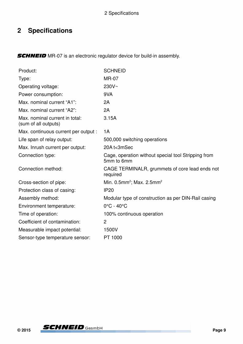
2 Specifications
SCHNEID MR-07 is an electronic regulator device for build-in assembly.
Product: SCHNEID
Type: MR-07
Operating voltage: 230V~
Power consumption: 9VA
Max. nominal current “A1”: 2A
Max. nominal current “A2”: 2A
Max. nominal current in total:(sum of all outputs)
3.15A
Max. continuous current per output : 1A
Life span of relay output: 500,000 switching operations
Max. Inrush current per output: 20A t<3mSec
Connection type: Cage, operation without special tool Stripping from 5mm to 6mm
Connection method: CAGE TERMINALR, grummets of core lead ends not required
Cross-section of pipe: Min. 0.5mm2; Max. 2.5mm2
Protection class of casing: IP20
Assembly method: Modular type of construction as per DIN-Rail casing
Environment temperature: 0°C - 40°C
Time of operation: 100% continuous operation
Coefficient of contamination: 2
Measurable impact potential: 1500V
Sensor-type temperature sensor: PT 1000
© 2015 Page 9

3 Terminal assignment / electrical connection
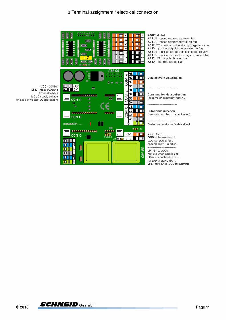
3 Terminal assignment / electrical connection
Wiring of main power / line entry:
Page 10 © 2016
3 Terminal assignment / electrical connection
© 2016 Page 11
4 Short discription of features
4 Short-description of features
The Schneid Ventilation Controller is a bilingual, free configurable control which covers a wide variety of selectable ventilation-applications. The control-display, monitoring-system and documentation are available in English and German.
Enabling of the system can be configured to be dependent from external request signals, time tables, and/or by certain room-temperature deviation.
Supply- and exhaust-air-ventilator can be configured as existing or not (for example for supply-air systems). Further the type ventilator- speeds can be controlled to fixed speed, fixed differential pressure, and differential pressure in dependence of air-quality measurements, such as CO² or relative humidity.
Heating – and/or cooling-registers can be configured, which will control the supply-air-temperature. The setpoints therefore are calculated by internal algorithms to ensure a stable and pleasant indoor climate.
Recovering energy can be used by controlled recuperation heat exchangers and/or bypass air flaps
The number of sensors is flexible as the control gives the possibility to use just the most important sensors that are necessary for the configured system or by setting sensors on several different positions, to achieve the most accurate control as possible.The control will recognize which sensors are connected and internally configure itself to them. Sensors which are necessary for the configured system, but might be not connected, are indicated by respective alarm messages, informing the user of this condition.
Filter- and/or belt-protection can be chosen to be monitored and alerted by digital or analogue signals.
A clear menu prompt leads the user through parameters for end-users such as a protected menu level for expert and/or initial configuration.
Fault messages can be divided into 3 different common fault priorities. This gives the possibility to determine if messages are just displayed and/or alerted, locked software-internally or locked by external hardware and might need acknowledgement by (also configurable) automatic and/or manual acknowledge functions.
Standardized visualisation software will automatically adapt to the system-configuration and thereby allow a fast and easy connection to monitoring software with –if required- worldwide remote access to the system.
The SCHNEID ventilation controller also provides a platform, which allows a variety ofextensions, possibilities and technical solutions.
Page 12 © 2015
5 Assignment of keys
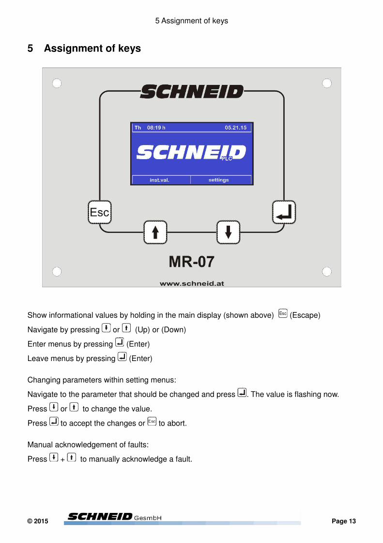
5 Assignment of keys
Show informational values by holding in the main display (shown above) (Escape)
Navigate by pressing or (Up) or (Down)
Enter menus by pressing (Enter)
Leave menus by pressing (Enter)
Changing parameters within setting menus:
Navigate to the parameter that should be changed and press . The value is flashing now.
Press or to change the value.
Press to accept the changes or to abort.
Manual acknowledgement of faults:
Press + to manually acknowledge a fault.
© 2015 Page 13
6 Instantaneous values menu
6 Instantaneous values menu
Enter the menu from the main display, by marking “inst.val.” and press the (Enter) Button.
The instantaneous value menu shows values of the actual operation of the system. The menu separates into 4 sub-menus, which are explained below.
6.1 Operation values
Shows the most important system values, such as speed and differential pressure of the ventila-tors, room- and supply-temperatures and their setpoints, as well as heat- and cooling-register temperatures and setpoints.
6.2 In-/Outputs
Shows the actual condition of all digital and analogue in- and outputs.
Press (Enter) to switch the displaying of digital inputs between act./n.act. (Software interpre-ted NO/NC) and open/close (effective condition of input).
6.3 Fault messages
Shows the condition and assignment of fault messages.
A highlighted text indicates an active fault.The “x” on the right side of the display indicates if a fault is assigned to the chosen common fault group.
6.4 Fault journal
Shows a historical journal of faults with date and time.
Page 14 © 2015

7 Settings menu
7 Settings menu
Press several times to leave any eventually opened sub-menu.
Press or to change to “settings” and press (Enter) to enter.The display will show a list of the available internal menus. Enter the desired sub-menu by
pressing (Enter).
7.1 General settings
P1 – Language/Sprache
Switches the display language between English and German.
P2 – room temperature during enhancement
Defines the room-temperature setpoint during enhancement times.
The enhancement times are defined separately in the same named sub-menu of general settings (see 7.9 Enhancement times).
P3 - room temperature outside enhancement
Defines the room-temperature setpoint during non-enhancement times.
The enhancement times are defined separately in the same named sub-menu of general settings (see 7.9 Enhancement times).
P4 – minimum supply air temperature
The setpoint for supply air is calculated internally. This parameter defines the lower limit of this calculation or in other word, the lowest possible supply air temperature.
P5 – maximum supply air temperature
The setpoint for supply air is calculated internally. This parameter defines the upper limit of this calculation or in other word, the highest possible supply air temperature.
© 2016 Seite 15
7 Settings menu
7.2 Supply air fan
P11 – minimum speed supply air
Sets the lower speed limit of the fan (if speed controlled).
P12 – maximum speed supply air
Sets the upper speed limit of the fan (if speed controlled).
P13 – fixed speed supply air
Sets speed of the fan (if not speed controlled).
P15 – differential pressure 1 - 2point curve
If the differential pressure control is set to be dependent from an air quality sensor, this parameter sets the speed at the beginning of the curve.
P16 – differential pressure 2 - 2point curve
If the differential pressure control is set to be dependent from an air quality sensor, this parameter sets the speed at the end of the curve.
Seite 16 © 2016
7 Settings menu
7.3 Exhaust air fan
P21 – minimum speed exhaust air
Sets the lower speed limit of the fan (if speed controlled).
P22 – maximum speed exhaust air
Sets the upper speed limit of the fan (if speed controlled).
P23 – fixed speed exhaust air
Sets speed of the fan (if not speed controlled).
P25 – differential pressure 1 - 2point curve
If the differential pressure control is set to be dependent from an air quality sensor, this parameter sets the speed at the beginning of the curve.
P26 – differential pressure 2 - 2point curve
If the differential pressure control is set to be dependent from an air quality sensor, this parameter sets the speed at the end of the curve.
© 2016 Seite 17

7 Settings menu
7.4 Heating coil
P31 – minimum return heatregister
Sets the lower limit of the return temperature (if a return-temperature sensor is installed).
P32 – cut off timer heatregister
The register will continue running for this time, after a deactivation condition (for example after the desired supply air temperature is reached).
P33 – hysteresis temperature-request heatregister
If the heatregister is activated by room-temperature difference, this parameter determines the height of the difference between room temperature setpoint and actual temperature, to activate the register.
P35 – heatregister controls supply air temp.
If acticated, the heatregister will control the supply air temperatur instead of the water supply temperature in the register circuit.Activation could be necessary if no water sensors are installed or if their measurement is not accurate enough.
7.5 Cooling coil
P41 – maximum return cooling register
Sets the upper limit of the return temperature (if a return-temperature sensor is installed).
P42 – cut off timer cooling register
The register will continue running for this time, after a deactivation condition (for example after the desired supply air temperature is reached).
P43 – hysteresis temperature-request cooling register
If the coolregister is activated by room-temperature difference, this parameter determines the height of the difference between room temperature setpoint and actual temperature, to activate the register.
P45 – coolregister controls supply air temp.
If acticated, the coolregister will control the supply air temperatur instead of the water supply temperature in the register circuit.Activation could be necessary if no water sensors are installed or if their measurement is not accurate enough.
Seite 18 © 2016
7 Settings menu
7.6 Recuperation heat exchanger
P51 – minimum recuperation ratio
Sets the minimum position of the recuperation air flap.
P52 – frost protective temp recuperator
Bypasses the recuperator if the referenced temperature falls below the limit or controls the exhaust air temperature to the setpoint, if referenced to be steady controlled (next parameter).An exception is the setting with respect to the exhaust air temperature, which can be controlled continuously to the frost protection temperature, so as not to fall below, but still achieve the maximum possible heat recovery.
P53 – frost protective temp reference
0 .. frost protective temperature measured at supply air sensor1 .. frost protective temperature measured at exhaust air sensor2 .. frost protective temperature measured at exhaust air sensor and steady controlled*
*steady control of this temperature enables the maximum possible recuperation ratio while frost protection of the recuperator.
7.7 Bypass air flap
P56 – minimum outside air ratio
Sets the minimum position of the bypass air flap.
P57 – bypass air flap controlled to air quality
This setting will only have effect to steady controlled (0-10V) actors.
The position of the air flap will be controlled in dependence of a 2-point-curve referenced to the CO² value in the room.
The function allows higher outside air ratio with higher CO² value.
© 2016 Seite 19
7 Settings menu
7.8 Ventilating times
Ventilating times
If the ventilating system is activated by a time schedule, this menu gives possibility to set the activation times.
The times can either be set for every day individually or for an overall block from Monday to Sunday.
If only one day needs to be set different from all other weekdays, set the block mon-sun at fist and set the individual day afterwards.
7.9 Enhancement times
Enhancement times
This schedule determines, when the room temperature is controlled to the enhanced value “room temperature during enhancement “ (see P2 – room temperature during enhancement).
Outside those times, the room temperature will be controlled to the value “room temperature outside enhancement “ (see P3 - room temperature outside enhancement).
Seite 20 © 2016

10 Internal Menu
8 Software update (manually)
Prepare:
– MMC card
– UG07.bin
– computer with MMC slot
The MMC card can be taken from the control, where it is find on the upper back of the display.
Never remove the MMC card completely from the control, as an automatic update (by databus-interface) will not be possib le anymore.
The software version is always contained in the file UG07.bin which can be obtained from your supplier.
Copy the UG07.file onto the MMC card.
Place the MMC card in the back of the display again.
Restart the control by executing a cold boot (see 10.1 Test-Display) or by disconnecting the control from its power supply for a moment.
The control display shows, if the MMC was found and, (if the software on the MMC is a later version) if the control is updating.
Check the new software version by holding after update, or restart with a new formatted MMC card, if the update didn’t work.
© 2015 Seite 21
Start-up settings
9 Start-up settings
This chapter lists the most important configurations, which should be done within the first start-up of the system. This includes enabling the existing system parts, as well as (if a monitoring system is in use) configuration of the databus-interface.
If a databus interface exists, it is possible just to do the configuration of the interface and set the rest of the parameters remotely on the monitoring system.
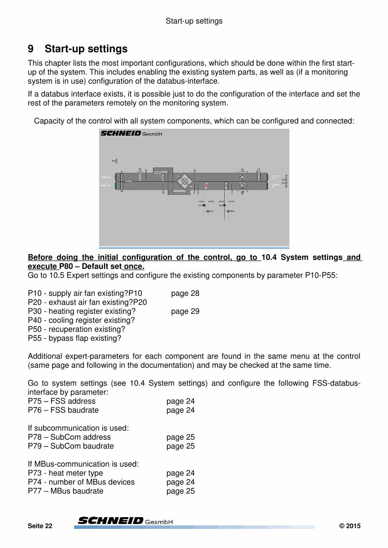
Capacity of the control with all system components, which can be configured and connected:
Before doing the initial configuration of the control, go to 10.4 System settings and execute P80 – Default set once.Go to 10.5 Expert settings and configure the existing components by parameter P10-P55:
P10 - supply air fan existing?P10 page 28P20 - exhaust air fan existing?P20P30 - heating register existing? page 29P40 - cooling register existing?P50 - recuperation existing?P55 - bypass flap existing?
Additional expert-parameters for each component are found in the same menu at the control (same page and following in the documentation) and may be checked at the same time.
Go to system settings (see 10.4 System settings) and configure the following FSS-databus-interface by parameter:P75 – FSS address page 24P76 – FSS baudrate page 24
If subcommunication is used: P78 – SubCom address page 25P79 – SubCom baudrate page 25
If MBus-communication is used: P73 - heat meter type page 24P74 - number of MBus devices page 24P77 – MBus baudrate page 25
Seite 22 © 2015

10 Internal menu
10 Internal Menu – all parameters
Enter the internal menu the following way:
Press several times to leave any eventually opened sub-menu.
Hold + for approximately 5 seconds to enter the internal menu.
The display will show a list of available internal menus. Navigate to the desired menu and press
to enter.
Proceed with the following chapters, which are describing the internal sub menus.
© 2016 Seite 23

10 Internal menu
10.1 Test-Display
The test display shows instantaneous system values of communication, such as:- MBus- SubCom- FSS
The test-display also gives the possibility to execute a cold-boot and restart the control. This is for example necessary, when doing a software update by changing the MMC (see 8 Software update (manually)).
10.2 Output test
The output test allows to manually switch all digital and analogue outputs. This is for example helpful, when point-testing the system before startup.
10.3 Set date & time
Press to make the first digit (day) start flashing.
Press or to change the week-day.
Press to apply the change.
Proceed the same way with every other until none of them is flashing anymore.
Abort any changes by pressing .
Seite 24 © 2016

10 Internal menu
10.4 System settings
Press several times to leave any eventually opened sub-menu.
Hold + for approximately 5 seconds to enter the internal menu.
The display will show a list of available internal menus. Navigate to “system settings”
and press
P68 - SIP number
This parameter is used similar as an address, if internet or VMware is used as a data interface, instead of a direct network- or cable-connection to a monitoring PC.
This function requires special settings at the network router of the control, as well as of the PC. As configurations vary from system to system, please ask your supplier for further information.
P72 - send data to SinVis?
This parameter is used if the monitoring system uses SinVis as a web-based kind of monitoring system.
SinVis has to be ordered, activated and licensed. Please ask your supplier for further information.
P73 - heat meter type
This parameter can usually stay set to “1”, as this is provided for standard MBus devices, whose protocol can be detected automatically by the software.
If special types of meters are used, which may not be in the protocol yet, this parameter may be changed to another value on advice of the supplier.
P74 - number of MBus devices
Set to the number of connected meters (e.g. heat-meters or electricity-meter).Find information on interface-connection of meters on page 9.
P75 – FSS address
Address of the control for communication with the monitoring system.
P76 – FSS baudrate
Baudrate (speed of communication) of the control for communication with the monitoring system.
© 2016 Seite 25
10 Internal menu
P77 – MBus baudrate
Baudrate (speed of communication) of the control for communication with meters.
P78 – SubCom address
Address of the control for internal communication with other controls or control-extensions.
P79 – SubCom baudrate
Baudrate (speed of communication) of the control for internal communication with other controls or control-extensions.
P80 – Default set
Resets all parameter to factory setting.
P81 – common fault 1 byte 1 P82 – common fault 1 byte 2 P83 – common fault 1 byte 3 P84 – common fault 1 byte 4 P85 – common fault 2 byte 1 P86 – common fault 2 byte 2 P87 – common fault 2 byte 3 P88 – common fault 2 byte 4 P89 – common fault 3 byte 1 P90 – common fault 3 byte 2 P91 – common fault 3 byte 3 P92 – common fault 4 byte 4
Assigns faults to the respective common fault.
common fault 1: critical faults which require acknowledgement (either manual or automatic if assigned)
common fault 2: critical faults which don’t require acknowledgement
common fault 3: less critical faults or warnings
Seite 26 © 2016
10 Internal menu
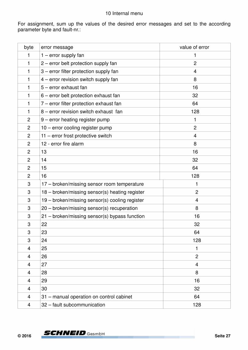
For assignment, sum up the values of the desired error messages and set to the according parameter byte and fault-nr.:
byte error message value of error
1 1 – error supply fan 1
1 2 – error belt protection supply fan 2
1 3 – error filter protection supply fan 4
1 4 – error revision switch supply fan 8
1 5 – error exhaust fan 16
1 6 – error belt protection exhaust fan 32
1 7 – error filter protection exhaust fan 64
1 8 – error revision switch exhaust fan 128
2 9 – error heating register pump 1
2 10 – error cooling register pump 2
2 11 – error frost protective switch 4
2 12 - error fire alarm 8
2 13 16
2 14 32
2 15 64
2 16 128
3 17 – broken/missing sensor room temperature 1
3 18 – broken/missing sensor(s) heating register 2
3 19 – broken/missing sensor(s) cooling register 4
3 20 – broken/missing sensor(s) recuperation 8
3 21 – broken/missing sensor(s) bypass function 16
3 22 32
3 23 64
3 24 128
4 25 1
4 26 2
4 27 4
4 28 8
4 29 16
4 30 32
4 31 – manual operation on control cabinet 64
4 32 – fault subcommunication 128
© 2016 Seite 27
10 Internal menu
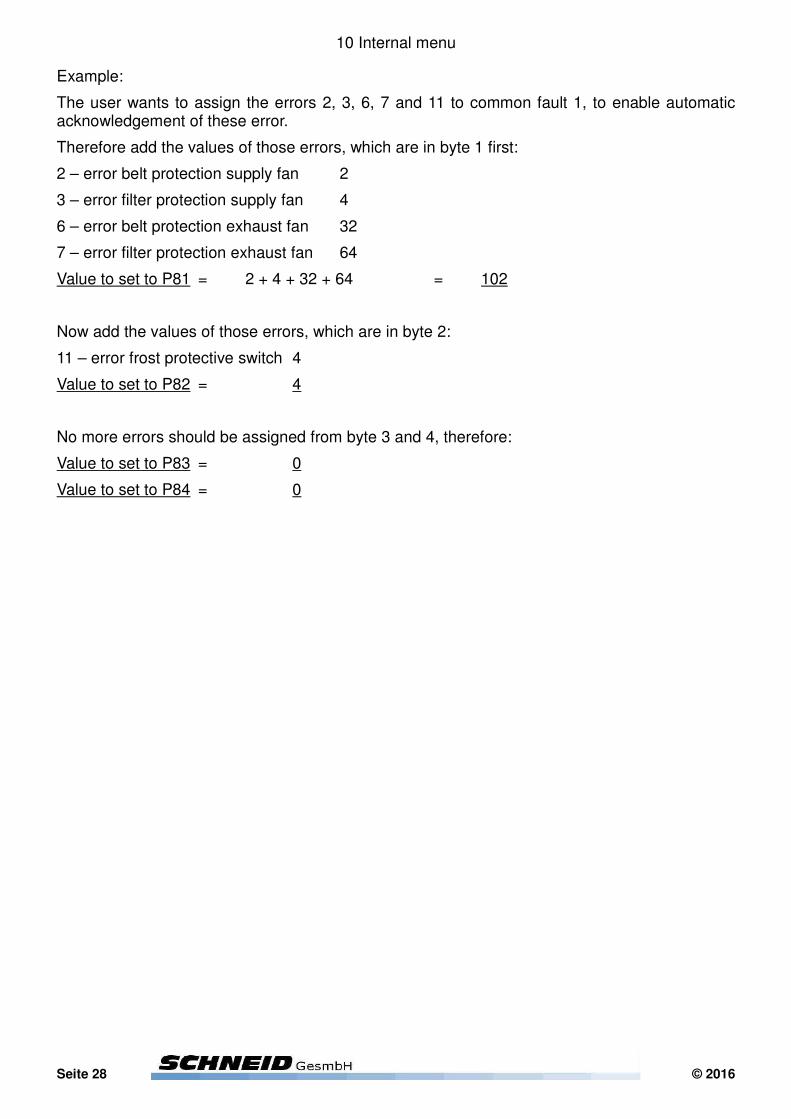
Example:
The user wants to assign the errors 2, 3, 6, 7 and 11 to common fault 1, to enable automatic acknowledgement of these error.
Therefore add the values of those errors, which are in byte 1 first:
2 – error belt protection supply fan 2
3 – error filter protection supply fan 4
6 – error belt protection exhaust fan 32
7 – error filter protection exhaust fan 64
Value to set to P81 = 2 + 4 + 32 + 64 = 102
Now add the values of those errors, which are in byte 2:
11 – error frost protective switch 4
Value to set to P82 = 4
No more errors should be assigned from byte 3 and 4, therefore:
Value to set to P83 = 0
Value to set to P84 = 0
Seite 28 © 2016

10 Internal menu
P97 – manual common fault
Gives the operator the possibility to switch the common fault outputs manually:
0 .. fault-outputs OFF
1 .. fault-outputs ON
9 .. fault-outputs AUTOMATIC
P98 – max impulse 3 point valves
Do not change this parameter unless otherwise instructed by manufacturer!
P247 – load settings from MMC
Loads all parameter settings from the MMC Card.
Requires a MMC, which has parameter information stored (see parameter 248)
P248 – save settings to MMC
Saves the parameter configuration of the control to the MMC, and allows sharing it with other controls, by executing parameter 247 at the other controls.
P249 – MBus configuration impulse-reading
Necessary, if battery-meters are in use, which block their interface after a certain amount of readings per day.
This parameter determines, which of the connected meters such are.
The selection is done by the meter-address and its binary value. Sum up the binary values of meters addresses to enable impulse reading of multiple meters (see page 25 for an explanation on how to sum up binary values).
P250 – MBus reading interval
Determines the interval between two readings of impulse-reading configured meters.
1440min .. once a day
720min .. twice a day
480min .. three times a day
360min .. four times a day
© 2016 Seite 29
10 Internal menu
10.5 Expert settings
Press several times to leave any eventually opened sub-menu.
Hold + for approximately 5 seconds to enter the internal menu.
The display will show a list of available internal menus. Navigate to “expert settings” and press
.
P10 - supply air fan existing?
P20 - exhaust air fan existing?
Choose yes, if this system-part exists.
P13 - supplyspeed controls?
P23 - exhaustspeed controls?
Only valid, if fan exists and, if fan is speed controlled:
0 .. fixed speed
1 .. speed controlling fixed delta-P value (delta-P sensor must be connected)
2 .. speed controlling air quality (CO²- or relative-humidity-sensor AND delta-P sensor must be connected)
P120 - supply fan I-factor
P121 - supply fan P-regionP130 - exhaust fan I-factorP131 - exhaust fan P-region
Do not change this parameter unless otherwise instructed by manufacturer!
P122 - supply fan CO² point 1
P123 - supply fan CO² point 2P132 - exhaust fan CO² point 1P133 - exhaust fan CO² point 2
Only valid, if fan is speed controlled to air quality sensor.
The parameters determine where the delta-P-setpoint has its minimum and its maximum value, according to the actual air quality reading.
Seite 30 © 2016
10 Internal menu
P126 – supply fan room-diff. pt.1
P127 - supply fan room-diff. pt.2
P136 - exhaust fan room-diff. pt.1
P137 - exhaust fan room-diff. pt.2
Only valid if the fan was set to be controlled in reference to a room temperature sensor.These parameters define the min and max values of the delta-P setpoint, dependend from the differential room temperature.
P104 - filter protection supply fan?
P107 - filter protection exhaust fan?
Choose yes, if this system-part exists.
P105 - analogue/digital filter protection supply fan
P108 - analogue/digital filter protection exhaust fan
Only valid, if filter protection exists.
This parameter gives the operator the possibility to invert the logic of the filer protection signal, or to set an analogue input signal (for pressure sensor):
0 .. closed contact = request (pressure-switch must be connected)
1 .. open contact = request (pressure-switch must be connected)
2 .. analogue input signal (pressure-sensor must be connected)
P106 - max. pressure supply air filter protection
P109 - max. pressure exhaust air filter protection
Only valid, if filter protection exists and, if signal is set to analogue input.
This parameter determines the maximum pressure loss of the filter in operation, after an error message will be executed.
The error message is software internally locked and must be acknowledged.
P124 – belt protection supply fan?
P134– belt protection exhaust fan?
Only valid, if fan and delta-P-sensor exists.
Choose yes, if the delta-P-sensor is used for a belt protective function.
© 2016 Seite 31

10 Internal menu
P125 - min. pressure supply air filter protection
P135 - max. pressure exhaust air filter protection
Only valid, if belt protection exists.
This parameter determines the minimum pressure of the fan in operation, unless an error message will be executed.
The error message is software internally locked and must be acknowledged.
Seite 32 © 2016

10 Internal menu
P30 - heating register existing?
P40 - cooling register existing?P50 - recuperation existing?P55 - bypass flap existing?
Choose yes, if this system-part exists.
P140 – incoming temp. hysteresis heatregister on
P160 – incoming temp. hysteresis coolregister on
Only valid, if register exists.
This parameter determines the difference between supply air setpoint and incoming temperature, which needs to be exceeded to enable the register.
P141 – supply hysteresis heatregister on
P161 – supply hysteresis coolregister on
Only valid, if register exists.
This parameter determines the difference between supply air setpoint and supply temperature, which needs to be exceeded to enable the register.
P148 – heatregister-setpoint min. value
P149 – heatregister-setpoint max. valueP168 – coolregister-setpoint min. valueP169 – coolregister-setpoint max. value
Only valid, if register exists.
This parameter determines the minimum/maximum value for the setpoint at the heating/cooling register.
© 2016 Seite 33

10 Internal menu
P142 - heatregister-setpoint P-region 1
P143 - heatregister-setpoint offset 2P144 - heatregister-setpoint P-region 2P145 - heatregister-setpoint P-region 3P146 - heatregister-setpoint I-factor 4P147 - heatregister-setpoint resettime 4P162 - coolregister-setpoint P-region 1P163 - coolregister-setpoint offset 2P164 - coolregister-setpoint P-region 2P165 - coolregister-setpoint P-region 3P166 - coolregister-setpoint I-factor 4P167 - coolregister-setpoint resettime 4
Do not change this parameter unless otherwise instructed by manufacturer!
P150 - heatregister-valve timer
P151 - heatregister-valve I-factorP152 - heatregister-valve P-regionP170 - heatregister-valve timerP171 - heatregister-valve I-factorP172 - heatregister-valve P-region
Do not change this parameter unless otherwise instructed by manufacturer!
P153 – sequence function heatregister
P173 – sequence function coolregister
Only valid if register and recuperation flap exists.
The sequence function allows the register to enable only if the recuperation flap has fully opened. Activation of the sequence function is recommended if there is no temperature sensor in between register and recuperator.
P154 – sequence disabling position heatregister
P174 – sequence disabling position coolregister
Only valid if sequence function is activated.
The parameter defines the valve position which need to be underrun that the heatregister can be disabled and control is moved to the recuperator.
P155 – pre-heating heatregister
If activated, the heating register will start a pre-heating sequence initially to any start of the air handling system, if the outside temperature lies below the setpoint (next parameter) or independent from the outside temperature, if no such sensor has been installed.
Seite 34 © 2016
10 Internal menu
The pre-heating is completed if the return sensor reaches 20°C.If no return sensor is installed, the pre-heating is completed if the supply sensor reaches 40°C.If both return and supply sensor are not installed, the pre-heating will be completed after a fixed running time of 2 minutes.
P156 – pre-heating outside temperature
Only valid if pre-heating is activated.
See upper parameter for description.
P180 - recuperation-flap timer
P181 - recuperation-flap I-factorP182 - recuperation-flap P-region
Do not change this parameter unless otherwise instructed by manufacturer!
P185 - bypass-flap timer
P186 - bypass-flap I-factorP187 - bypass-flap P-region
Do not change this parameter unless otherwise instructed by manufacturer!
P188 – 2-point curve bypass-flap position pt. 1
P189 - 2-point curve bypass-flap position pt. 2
P291 - 2-point curve bypass-flap air quality pt. 1
P292 - 2-point curve bypass-flap air quality pt. 2
These parameters define the position of the bypass flap in dependence of the room air quality (CO²), if the respective bypass flap control has been activated (P57).
© 2016 Seite 35
10 Internal menu
P110 - supply air controls room?
Only valid, if any component for heating/cooling exists (cooling/heating register, recuperation, bypass flap) and a room temperature sensor exists.
Usually the room temperature is controlled by the ventilating system (set this parameter to Yes then)
If the ventilating system is used only for air exchange, or if a room temperature sensor is missing or not significant enough, this parameter gives the possibility to control the supply temperature to a fixed value, which is independent from the room temperature.
P111 - supply air offset 1
P112 - supply air P-region 2P113 - supply air exponent 2P114 - supply air resettime 4P115 - supply air I-factor 4
Do not change this parameter unless otherwise instructed by manufacturer!
P116 - supply air max. difference
This parameter determines the maximum difference between supply air setpoint and room temperature.
The parameter thereby prevents discomfort, caused by too cold or hot air, brought in by the ventilation system.
Seite 36 © 2016
10 Internal menu
P101 - enable signal mask VT
Choose how to enable and disable the ventilating system, by setting the value according to the following (bit-) mask:
0 .. always off (no frost protective function by software!!!)
1 .. external request (external request signal must be connected)
2 .. time table
3 .. request + time table
4 .. room thermostat (room temperature sensor must be connected)
5 .. request + thermostat
6 .. time table + thermostat
7 .. request + time table + thermostat
8 .. outside temperature use
9 .. outside temperature use + external release
P102 - hysteresis room-thermostat enabling
Only valid, if the enable signal mask is configured to be activated by room-thermostat function.
This parameter determines, how high the difference between room temperature and setpoint must be to enable the ventilation system.
The deactivation will be performed, if the setpoint is under-/overrun (cooling/heating) for half the configured hysteresis.
P103 - boolean logic external request signal
Only valid, if enable signal mask is configured to be activated by external request.
This parameter gives the operator the possibility to invert the logic of the external request signal:
0 .. closed contact = request
1 .. open contact = request
P190 – Follow-up time external request signal
Valid only, when the enable signal mask is configured to be activated by an external request. The follow-up time increases the ventilation release after an external request.
© 2016 Seite 37

10 Internal menu
P280 – timeout auto-acknowledge
Only valid, if auto-acknowledge is activated (set higher than 0).
Time between automatic acknowledge repeats.
P281 – # (number) of repeats auto-acknowledge
This parameter determines the number of automatic acknowledge signals, after an error message occurs.
The function can be deactivated (if only manual acknowledge is desired) by setting the value to 0.
P282 – auto-acknowledge restart?
Only valid, if auto-acknowledge is activated (set higher than 0).
If activated, the automatic acknowledge will restart with every new error message that occurs.
If deactivated, the automatic acknowledge will stay idle after the configured repeats, also, if a new error occurs.
Seite 38 © 2016

10 Internal menu
10.6 Manual operation
The menu allows the operator to override the control functions, for example switching on and off pumps, or to manually force a valve into a certain position.
It is absolutely not recommended to stay with a manual operation for a longer period of time, as every safety function is overwritten by the manual mode.
Always make sure, that the normal operation of the system is AUTOMATIC for ALL ACTUATORS.
Default value for automatic operation:
9 .. AUTOMATIC mode for digital actuators (pumps, flaps, 2/3-point valves, etc.)
101% .. AUTOMATIC mode for static actuators (static valves, positioning signals etc.)
Manual mode for (most of the) pumps, ventilators:
0 .. OFF
1 .. ON (automatic speed if speed controlled)
2 .. ON (manual speed if speed controlled) (AUTOMATIC if not speed controlled)
9 .. AUTOMATIC
Manual mode for 2-point valves:
0 .. CLOSE
1 .. OPEN
9 .. AUTOMATIC
Manual mode for 3-point valves:
0 .. STOP
1 .. OPEN
2 .. CLOSE
9 .. AUTOMATIC
Manual mode for static valves:
0-100% .. manual position
101% .. AUTOMATIC
© 2016 Seite 39

10 Internal menu
10.7 Sensor offset
The menu allows the operator to add a sensor offset (either negative or positive) to the temperature sensors.
10.8 Analogue offset
The menu allows the operator to add offsets (either negative or positive), as well as initial and fi-nal values to the analogue sensors (such as pressure-sensors).
Seite 40 © 2016
11 Troubleshooting
11 Troubleshooting
11.1 Communication
Sorting the data
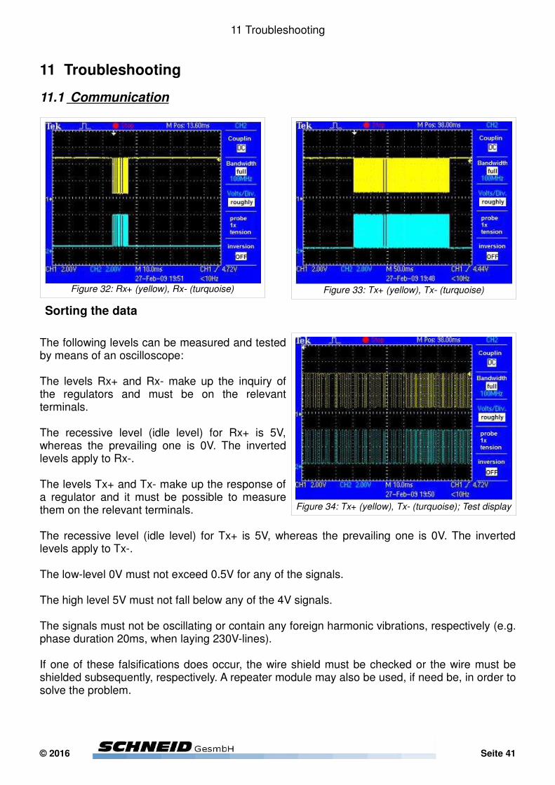
The following levels can be measured and tested by means of an oscilloscope:
The levels Rx+ and Rx- make up the inquiry of the regulators and must be on the relevant terminals.
The recessive level (idle level) for Rx+ is 5V, whereas the prevailing one is 0V. The inverted levels apply to Rx-.
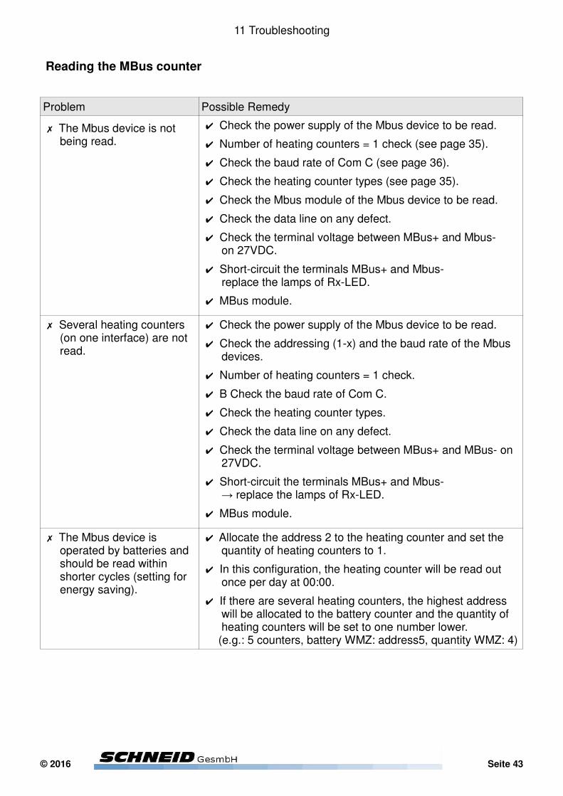
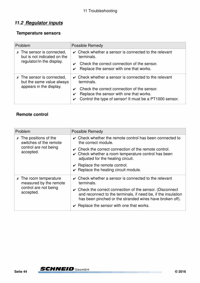
The levels Tx+ and Tx- make up the response of a regulator and it must be possible to measure them on the relevant terminals.
The recessive level (idle level) for Tx+ is 5V, whereas the prevailing one is 0V. The inverted levels apply to Tx-.
The low-level 0V must not exceed 0.5V for any of the signals.
The high level 5V must not fall below any of the 4V signals.
The signals must not be oscillating or contain any foreign harmonic vibrations, respectively (e.g. phase duration 20ms, when laying 230V-lines).
If one of these falsifications does occur, the wire shield must be checked or the wire must be shielded subsequently, respectively. A repeater module may also be used, if need be, in order to solve the problem.
© 2016 Seite 41
Figure 32: Rx+ (yellow), Rx- (turquoise) Figure 33: Tx+ (yellow), Tx- (turquoise)
Figure 34: Tx+ (yellow), Tx- (turquoise); Test display

11 Troubleshooting
Problem Possible Remedy
✗ The Rx and Tx LED on the module light up, but the TxR LEDs do not light up.
✔ Check the regulator address and baud rate Com A. ✔ Check whether the display system inquires for the regulator address (regler.dat, WinCOM).
✔ Check the correct connection of the data lines Rx and Tx.✔ Check the signal level by means of an oscilloscope.✔ (!) In a data network with a great number of receivers, it may take a longer time accordingly depending on the baud rate, until the respective regulator responds, which is indicated when the TxR LED flashes.
✔ Replace the RS422 module.
✗ (Almost) all LEDs on the RS422 module are constantly lit up.
✔ Faulty wiring of the paths Rx and/or Tx.
✔ Check the data line on any defects.
✔ Check the correct connection of the data lines Rx+, Rx-, Tx+, Tx-.
✔ Check the signal level by means of an oscilloscope, if necessary.
✔ Replace the RS422 module.
✗ All LEDs on the module are flashing correctly, but the regulator is not shown in the display.
✔ Check whether the respective regulator will really respond; this is indicated by a flashing of the TxR LED.
✔ Check the correct connection of the data lines Tx+, Tx-.✔ Check the signal level by means of an oscilloscope.✔ Replace the RS422 module.
✗ Correct responding of the regulator, which is indicated with the LEDs, but the regulator is not shown in the display.
✔ Check whether the respective regulator address is listed in regler.dat and whether the WinCOM program has been opened.
✔ Check whether there are sufficient licenses under WinCOM for each one of the connected regulators.
✔ Check whether the data converter has been connected.
✔ Check the signal level by means of an oscilloscope.
Seite 42 © 2016
11 Troubleshooting
Reading the MBus counter
Problem Possible Remedy
✗ The Mbus device is not being read.
✔ Check the power supply of the Mbus device to be read.
✔ Number of heating counters = 1 check (see page 35).
✔ Check the baud rate of Com C (see page 36).
✔ Check the heating counter types (see page 35).
✔ Check the Mbus module of the Mbus device to be read.
✔ Check the data line on any defect.
✔ Check the terminal voltage between MBus+ and Mbus- on 27VDC.
✔ Short-circuit the terminals MBus+ and Mbus- replace the lamps of Rx-LED.
✔ MBus module.
✗ Several heating counters (on one interface) are not read.
✔ Check the power supply of the Mbus device to be read.
✔ Check the addressing (1-x) and the baud rate of the Mbus devices.
✔ Number of heating counters = 1 check.
✔ B Check the baud rate of Com C.
✔ Check the heating counter types.
✔ Check the data line on any defect.
✔ Check the terminal voltage between MBus+ and MBus- on 27VDC.
✔ Short-circuit the terminals MBus+ and Mbus- → replace the lamps of Rx-LED.
✔ MBus module.
✗ The Mbus device is operated by batteries and should be read within shorter cycles (setting for energy saving).
✔ Allocate the address 2 to the heating counter and set the quantity of heating counters to 1.
✔ In this configuration, the heating counter will be read out once per day at 00:00.
✔ If there are several heating counters, the highest address will be allocated to the battery counter and the quantity of heating counters will be set to one number lower. (e.g.: 5 counters, battery WMZ: address5, quantity WMZ: 4)
© 2016 Seite 43
11 Troubleshooting
11.2 Regulator inputs
Temperature sensors
Problem Possible Remedy
✗ The sensor is connected, but is not indicated on the regulator/in the display.
✔ Check whether a sensor is connected to the relevant terminals.
✔ Check the correct connection of the sensor.
✔ Replace the sensor with one that works.
✗ The sensor is connected, but the same value always appears in the display.
✔ Check whether a sensor is connected to the relevant terminals.
✔ Check the correct connection of the sensor.
✔ Replace the sensor with one that works.
✔ Control the type of sensor! It must be a PT1000 sensor.
Remote control
Problem Possible Remedy
✗ The positions of the switches of the remote control are not being accepted.
✔ Check whether the remote control has been connected to the correct module.
✔ Check the correct connection of the remote control.✔ Check whether a room temperature control has been adjusted for the heating circuit.
✔ Replace the remote control.✔ Replace the heating circuit module.
✗ The room temperature measured by the remote control are not being accepted.
✔ Check whether a sensor is connected to the relevant terminals.
✔ Check the correct connection of the sensor. (Disconnect and reconnect to the terminals, if need be, if the insulation has been pinched or the stranded wires have broken off).
✔ Replace the sensor with one that works.
Seite 44 © 2016
11 Troubleshooting
11.3 Regulator outputs
Pump/fan control
Problem Possible Remedy
✗ The pump is not switched on.
✔ Switch on the inputs on the parameter level and check whether the pump is being controlled, and measure the voltage on the output (when the pump is connected and disconnected).
✔ Check the settings which control the release of the pump.✔ Check the sensors which control the release of the pump.✔ Check the position of the priority select switch.✔ Check the pump’s ability to function, if this pump is directly connected to voltage.
✗ The pump rotates at a too slow speed.
✔ Check the voltage on the output (when the pump is connected and disconnected).
✔ Change the rotational speed by means of a priority select switch (if available) on the pump.
© 2016 Seite 45
11 Troubleshooting
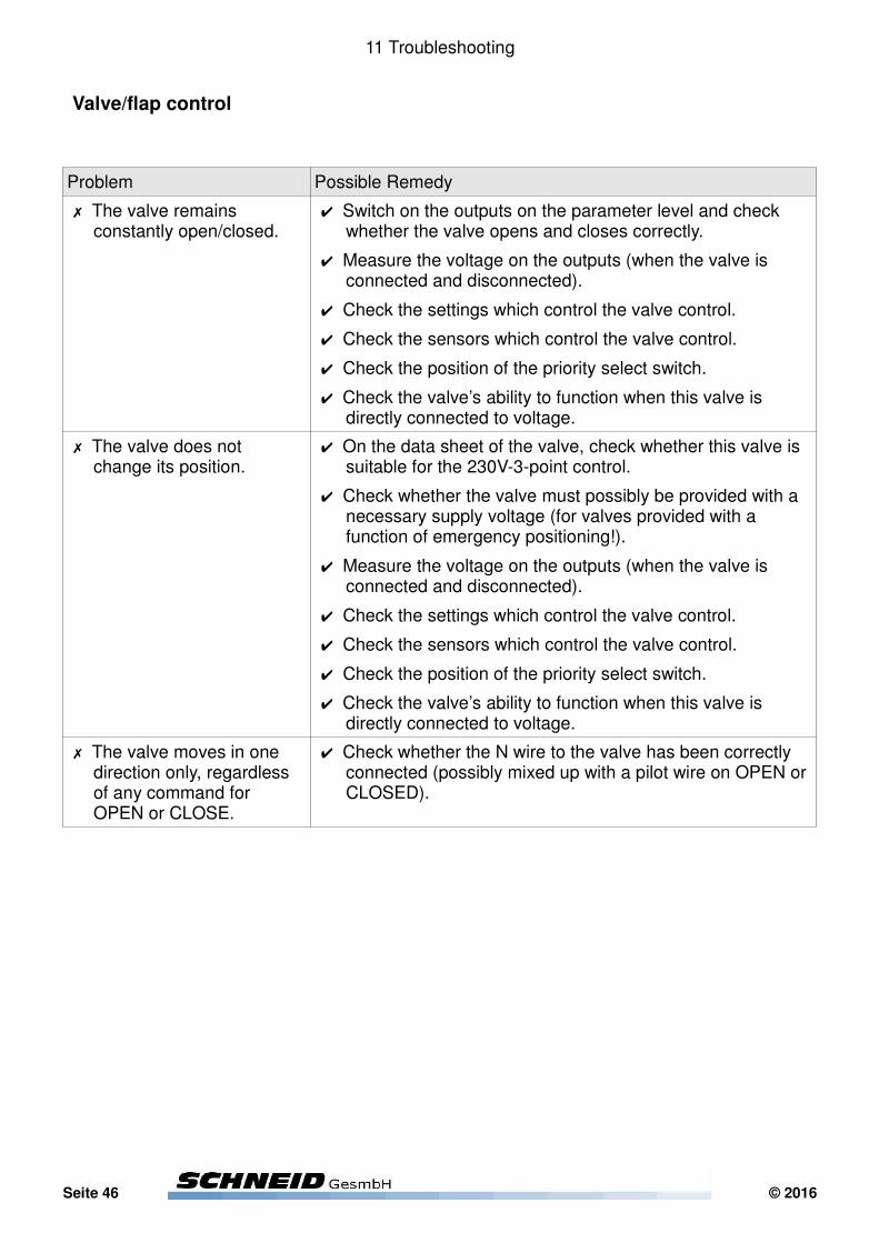
Valve/flap control
Problem Possible Remedy
✗ The valve remains constantly open/closed.
✔ Switch on the outputs on the parameter level and check whether the valve opens and closes correctly.
✔ Measure the voltage on the outputs (when the valve is connected and disconnected).
✔ Check the settings which control the valve control.
✔ Check the sensors which control the valve control.
✔ Check the position of the priority select switch.
✔ Check the valve’s ability to function when this valve is directly connected to voltage.
✗ The valve does not change its position.
✔ On the data sheet of the valve, check whether this valve is suitable for the 230V-3-point control.
✔ Check whether the valve must possibly be provided with a necessary supply voltage (for valves provided with a function of emergency positioning!).
✔ Measure the voltage on the outputs (when the valve is connected and disconnected).
✔ Check the settings which control the valve control.
✔ Check the sensors which control the valve control.
✔ Check the position of the priority select switch.
✔ Check the valve’s ability to function when this valve is directly connected to voltage.
✗ The valve moves in one direction only, regardless of any command for OPEN or CLOSE.
✔ Check whether the N wire to the valve has been correctly connected (possibly mixed up with a pilot wire on OPEN or CLOSED).
Seite 46 © 2016
Index
Stichwortverzeichnis
2-point curve bypass-flap air quality pt. 1....................................................................................352-point curve bypass-flap air quality pt. 2....................................................................................352-point curve bypass-flap position pt. 1.......................................................................................352-point curve bypass-flap position pt. 2.......................................................................................35Analogue offset...........................................................................................................................40analogue/digital filter protection exhaust fan...............................................................................31analogue/digital filter protection supply fan.................................................................................31Assignment of keys.....................................................................................................................13auto-acknowledge restart?..........................................................................................................38belt protection exhaust fan?.......................................................................................................31belt protection supply fan?..........................................................................................................31boolean logic external request signal..........................................................................................37Bypass air flap............................................................................................................................19bypass air flap controlled to air quality........................................................................................19bypass flap existing?...................................................................................................................33bypass-flap I-factor.....................................................................................................................35bypass-flap P-region...................................................................................................................35bypass-flap timer.........................................................................................................................35Communication...........................................................................................................................41Cooling coil.................................................................................................................................18cooling register existing?............................................................................................................33coolregister controls supply air temp...........................................................................................18coolregister-setpoint I-factor 4....................................................................................................34coolregister-setpoint max. value.................................................................................................33coolregister-setpoint min. value..................................................................................................33coolregister-setpoint offset 2.......................................................................................................34coolregister-setpoint P-region 1..................................................................................................34coolregister-setpoint P-region 2..................................................................................................34coolregister-setpoint P-region 3..................................................................................................34coolregister-setpoint resettime 4.................................................................................................34cut off timer cooling register........................................................................................................18cut off timer heatregister.............................................................................................................18Danger of freezing........................................................................................................................8Danger of scalding:.......................................................................................................................8Default set...................................................................................................................................26differential pressure 1 - 2point curve.........................................................................................16f.differential pressure 2 - 2point curve.........................................................................................16f.electrical connection...................................................................................................................10enable signal mask VT................................................................................................................37Enhancement times....................................................................................................................20Exhaust air fan............................................................................................................................17exhaust air fan existing?.............................................................................................................30exhaust fan CO² point 1..............................................................................................................30exhaust fan CO² point 2..............................................................................................................30exhaust fan I-factor.....................................................................................................................30exhaust fan P-region...................................................................................................................30exhaust fan room-diff. pt.1 .........................................................................................................31exhaust fan room-diff. pt.2..........................................................................................................31
© 2016 Seite 47

Index
exhaustspeed controls?..............................................................................................................30Expert settings............................................................................................................................30Fault journal................................................................................................................................14Fault messages...........................................................................................................................14filter protection exhaust fan?.......................................................................................................31filter protection supply fan?.........................................................................................................31fixed speed exhaust air...............................................................................................................17fixed speed supply air.................................................................................................................16frost protective temp recuperator................................................................................................19frost protective temp reference...................................................................................................19FSS address...............................................................................................................................25FSS baudrate..............................................................................................................................25General settings..........................................................................................................................15heat meter type...........................................................................................................................25Heating coil.................................................................................................................................18heating register existing?............................................................................................................33heatregister-setpoint I-factor 4....................................................................................................34heatregister-setpoint max. value.................................................................................................33heatregister-setpoint min. value..................................................................................................33heatregister-setpoint offset 2.......................................................................................................34heatregister-setpoint P-region 1..................................................................................................34heatregister-setpoint P-region 2..................................................................................................34heatregister-setpoint P-region 3..................................................................................................34heatregister-setpoint resettime 4................................................................................................34heatregister-valve I-factor...........................................................................................................34heatregister-valve P-region.........................................................................................................34heatregister-valve timer..............................................................................................................34hysteresis room-thermostat enabling..........................................................................................37hysteresis temperature-request cooling register.........................................................................18hysteresis temperature-request heatregister..............................................................................18In-/Outputs..................................................................................................................................14incoming temp. hysteresis coolregister on..................................................................................33incoming temp. hysteresis heatregister on..................................................................................33Instantaneous values menu........................................................................................................14Internal Menu..............................................................................................................................23Language/Sprache......................................................................................................................15load settings from MMC..............................................................................................................29manual common fault..................................................................................................................29Manual operation........................................................................................................................39max impulse 3 point valves.........................................................................................................29max. pressure exhaust air filter protection................................................................................31f.max. pressure supply air filter protection....................................................................................31maximum return cooling register.................................................................................................18maximum speed exhaust air.......................................................................................................17maximum speed supply air.........................................................................................................16maximum supply air temperature................................................................................................15MBus baudrate............................................................................................................................26MBus configuration impulse-reading...........................................................................................29MBus reading interval.................................................................................................................29min. pressure supply air filter protection.....................................................................................32minimum outside air ratio............................................................................................................19
Seite 48 © 2016

Index
minimum recuperation ratio........................................................................................................19minimum return heatregister.......................................................................................................18minimum speed exhaust air........................................................................................................17minimum speed supply air..........................................................................................................16minimum supply air temperature.................................................................................................15number of MBus devices............................................................................................................25Operation values.........................................................................................................................14Output test..................................................................................................................................24Permissible temperatures:............................................................................................................8pre-heating heatregister..............................................................................................................34pre-heating outside temperature.................................................................................................35Pump/fan control.........................................................................................................................45Reading the MBus counter.........................................................................................................43recuperation existing?.................................................................................................................33recuperation-flap I-factor.............................................................................................................35recuperation-flap P-region..........................................................................................................35recuperation-flap timer................................................................................................................35Regulator inputs..........................................................................................................................44Regulator outputs........................................................................................................................45Remote control............................................................................................................................44room temperature during enhancement......................................................................................15room temperature outside enhancement....................................................................................15Safty notes....................................................................................................................................8save settings to MMC.................................................................................................................29send data to SinVis?...................................................................................................................25Sensor offset...............................................................................................................................40sequence disabling position coolregister....................................................................................34sequence disabling position heatregister....................................................................................34sequence function coolregister...................................................................................................34sequence function heatregister...................................................................................................34Set date & time...........................................................................................................................24Settings menu.............................................................................................................................15Short-description of features.......................................................................................................12SIP number.................................................................................................................................25Software update..........................................................................................................................21Sorting the data...........................................................................................................................41Specifications................................................................................................................................9Start-up settings..........................................................................................................................22SubCom address........................................................................................................................26SubCom baudrate.......................................................................................................................26supply air controls room?............................................................................................................36supply air exponent 2..................................................................................................................36Supply air fan..............................................................................................................................16supply air fan existing?...............................................................................................................30supply air I-factor 4.....................................................................................................................36supply air max. difference...........................................................................................................36supply air offset 1........................................................................................................................36supply air P-region 2...................................................................................................................36supply air resettime 4..................................................................................................................36supply fan CO² point 1................................................................................................................30supply fan CO² point 2................................................................................................................30
© 2016 Seite 49
Index
supply fan I-factor.......................................................................................................................30supply fan P-region.....................................................................................................................30supply fan room-diff. pt.1 ...........................................................................................................31supply fan room-diff. pt.2............................................................................................................31supply hysteresis coolregister on................................................................................................33supply hysteresis heatregister on...............................................................................................33supplyspeed controls?................................................................................................................30System settings...........................................................................................................................25Temperature sensors..................................................................................................................44Terminal assignment...................................................................................................................10Test-Display................................................................................................................................24timeout auto-acknowledge..........................................................................................................38Troubleshooting..........................................................................................................................41Valve/flap control.........................................................................................................................46Ventilating times..........................................................................................................................20# (number) of repeats auto-acknowledge...................................................................................38
Seite 50 © 2016


Related Documents


