Document No: MP.0.2400.63 Revision No:2 Date Issued: 23/04/2018 Specification Title: Anti Pilferage Management System (APMS) inclusive of GSM Based Fuel Level Sensor on IR Diesel Locos LIST OF AMENDMENTS S. No. Amendment Date Revision Details 1. November 2009 0 First issue 2. March 2013 1 Specification reviewed and upgraded based on the performance of the equipment fitted. The following broad changes incorporated: • Emphasis on functional requirements • Equipment manufacturers are free to select sensing elements and process (with RDSO approval) • Common mechanical and electrical interface for modular interchangeability • Inclusion of both top mounted and side mounted sensors to cater for multiple tank designs used on all types of diesel electric locomotives • Improved repeatability, reduced variation due to disturbances of fuel surface. • Inclusion of calibration equipment 3. April2018 2 • Addition of GPS and GSM module with Fuel Level Sensor • Modification in clauses of Field trials and Deletion of AAR-5702 • Mounting arrangement of fuel level sensor in fuel level tank INDIAN RAILWAYS, RESEARCH DESIGNS & STANDARDS ORGANIZATION Page 1 of 16

Welcome message from author
This document is posted to help you gain knowledge. Please leave a comment to let me know what you think about it! Share it to your friends and learn new things together.
Transcript
Document No: MP.0.2400.63 Revision No:2 Date Issued: 23/04/2018 Specification Title: Anti Pilferage Management System (APMS) inclusive of GSM Based Fuel Level Sensor on IR Diesel Locos
LIST OF AMENDMENTS S. No. Amendment Date Revision Details
1. November 2009 0 First issue 2. March 2013 1 Specification reviewed and upgraded based on the performance
of the equipment fitted. The following broad changes incorporated:
• Emphasis on functional requirements • Equipment manufacturers are free to select sensing
elements and process (with RDSO approval) • Common mechanical and electrical interface for
modular interchangeability • Inclusion of both top mounted and side mounted
sensors to cater for multiple tank designs used on all types of diesel electric locomotives
• Improved repeatability, reduced variation due to disturbances of fuel surface.
• Inclusion of calibration equipment 3. April2018 2 • Addition of GPS and GSM module with Fuel Level
Sensor • Modification in clauses of Field trials and Deletion of
AAR-5702 • Mounting arrangement of fuel level sensor in fuel level
tank
INDIAN RAILWAYS, RESEARCH DESIGNS & STANDARDS ORGANIZATION Page 1 of 16
Document No: MP.0.2400.63 Revision No:2 Date Issued: 23/04/2018 Specification Title: Anti Pilferage Management System (APMS) inclusive of GSM Based Fuel Level Sensor on IR Diesel Locos
CONTENTS 0 Introduction ........................................................................................................................................... 4 1 Objectives and Scope of the specification ............................................................................................ 4 2 Terms and Abbreviations ...................................................................................................................... 4 3 Definitions ............................................................................................................................................. 4
3.1 Accuracy ....................................................................................................................................... 4 3.2 Calibration ..................................................................................................................................... 4 3.3 Measurement range ..................................................................................................................... 4 3.4 Precision (repeatability) ................................................................................................................ 4 3.5 Resolution (least count) ................................................................................................................ 4
4 Brief description of the system ............................................................................................................. 4 5 General requirements ........................................................................................................................... 5
5.1 Manufacturers qualification ........................................................................................................... 5 5.2 Equipment Requirements ............................................................................................................. 5
6 Functional requirements ....................................................................................................................... 5 6.1 Type of fuel ................................................................................................................................... 6 6.2 Mounting arrangement of sensors ................................................................................................ 6 6.3 Electrical interface ........................................................................................................................ 7 6.4 Measurement requirements .......................................................................................................... 7 6.5 Ingress protection ......................................................................................................................... 8 6.6 Impact Rating................................................................................................................................ 8 6.7 Calibration ..................................................................................................................................... 8
7 Technical requirements ........................................................................................................................ 8 8 Applicable drawings .............................................................................................................................. 8 9 Safety requirements ............................................................................................................................. 9
9.1 Reference environmental conditions ............................................................................................ 9 10 Referred standards ........................................................................................................................... 9 11 Maintenance and diagnostic aid ....................................................................................................... 9 12 Documents required from supplier ................................................................................................... 9 13 Warranty ......................................................................................................................................... 10 14 Tests & Verification ......................................................................................................................... 10
14.1 Test standards to be indicated ................................................................................................... 10 14.2 Sampling plan ............................................................................................................................. 10
15 Types of tests ................................................................................................................................. 10 15.1 Type test and field trials .............................................................................................................. 10 15.2 Routine test................................................................................................................................. 11 15.3 Acceptance test .......................................................................................................................... 11 15.4 Makers test certificate for outsourced item ................................................................................. 11
16 Painting, labeling and marking ....................................................................................................... 11 17 Packaging and delivery/shipment ................................................................................................... 12 18 IPR disclaimer pin pointing responsibility for violation if any on supplier ....................................... 12
18.1 Undertaking by equipment manufacturer ................................................................................... 12 18.2 Declaration of confidentiality of submitted documents by manufacturers .................................. 12
LIST OF FIGURES Figure 1: Schematic of Remote fuel monitoring 6 LIST OF TABLES Table 1: Terms & Abbreviations 4 Table 2: Fuel tank drawings and locomotive class 6
INDIAN RAILWAYS, RESEARCH DESIGNS & STANDARDS ORGANIZATION Page 2 of 16
Document No: MP.0.2400.63 Revision No:2 Date Issued: 23/04/2018 Specification Title: Anti Pilferage Management System (APMS) inclusive of GSM Based Fuel Level Sensor on IR Diesel Locos Table 3: Tank drawing and approximate range of measurement 7 Table 4: Resolution, accuracy and precision requirements 8 Table 5: Reference Environmental Conditions 9 LIST OF REFERENCED DOCUMENTS S. No. Document name / number 1. MP.0.2400.26 Specification of MBCS Systems for ALCO locomotives 2. RDSO Specification for AC-AC traction system
a) MP.0.2400.43. for AC-AC traction system b) MP.0.2400.67 for Dual cab AC-AC traction system
LIST OF ANNEXURES S. No. Document name / number
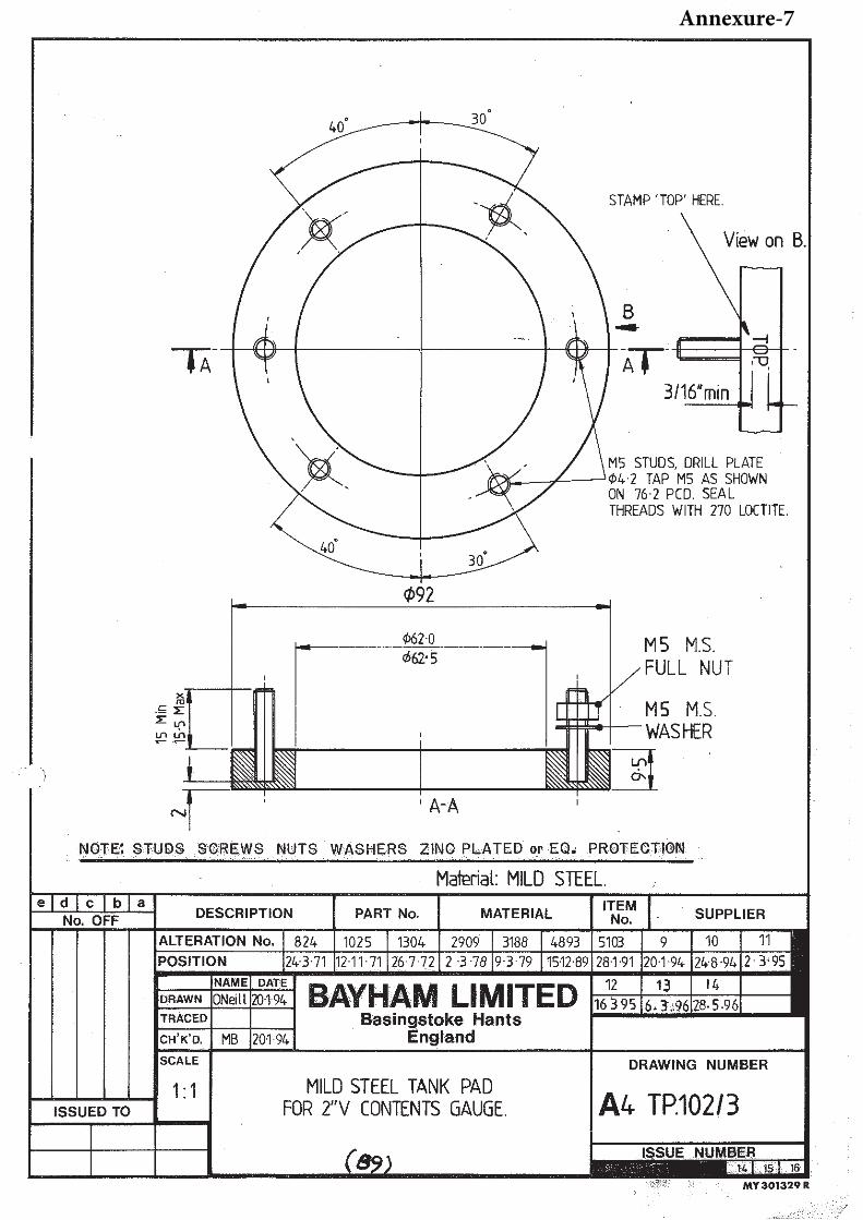
1. Interface Control Document 2. 3D Diagram of the tank in Diesel Locomotives 3. Drawing number 10630498_1(1-5-2-3-4&5) 4. Drawing number 11532348-TPL-9323-a-A01 5. Drawing number 11034555-TPL-6115-ee-roll_20080314_0001 6. Drawing number 11030033-Z-WDM3A 7. A4 TP.102/3 B9 Tank pad (Used under permission of Bayham Ltd. Basingstoke Hampshire, UK)
INDIAN RAILWAYS, RESEARCH DESIGNS & STANDARDS ORGANIZATION Page 3 of 16
Document No: MP.0.2400.63 Revision No:2 Date Issued: 23/04/2018 Specification Title: Anti Pilferage Management System (APMS) inclusive of GSM Based Fuel Level Sensor on IR Diesel Locos
0 Introduction This document describes sensor system for measuring fuel level of diesel electric locomotives. The described system senses the fuel level for the information of the crew and also enables remote monitoring for fuel level of the diesel locomotive.
This document also includes requirements for equipment required for calibration that is needed during initial setup and for periodic checks of sensor performance.
1 Objectives and Scope of the specification This document specifies the requirements, testing and evaluation criteria of GSM Based fuel level sensor system suitable for all diesel electric locomotives for Indian Railways for real time remote fuel level monitoring.
2 Terms and Abbreviations S. No Term / Abbreviation Description 1. AAR American Association of Railroads 2. DLW Diesel Locomotive Works, Varanasi 3. DMW, DLMW Diesel Loco Modernization Works, Patiala 4. LCC Locomotive Control Computer 5. MBCS Microprocessor Based Control System 6. PU Production Units 7. RDSO Research Designs &Standards Organisation 8. ZR Zonal Railways Table 1: Terms & Abbreviations
3 Definitions Unless otherwise specifically stated the following terms shall be defined as given below.
3.1 Accuracy The error between a measured reading and the true value of that measurement.
3.2 Calibration The comparison of a device with unknown accuracy to a device with a known, accurate standard to determine and eliminate any variation in the device being checked.
3.3 Measurement range The limits of measurement values that can be measured by the equipment.
3.4 Precision (repeatability) The measure of ability of the equipment to repeat the same measurement over a period of time. This shall be measured as a difference between the minimum and maximum measurement values for a finite set of readings.
3.5 Resolution (least count) The smallest change in a measured value that the equipment can detect.
4 Brief description of the system The fuel level sensor system shall be designed to be suitable for measurement of fuel level on diesel locomotives of Indian Railways under standstill condition and also during run.
The complete sensor system is generally expected to consist of the following
• Fuel level sensor along with processor unit, GSM Module, GPS module and antenna
• Mechanical mounting system for fitment on the fuel tank(s) (as required by the design and location of the fuel tank) consisting of flanges, blanking flanges, gaskets and fasteners.
INDIAN RAILWAYS, RESEARCH DESIGNS & STANDARDS ORGANIZATION Page 4 of 16
Document No: MP.0.2400.63 Revision No:2 Date Issued: 23/04/2018 Specification Title: Anti Pilferage Management System (APMS) inclusive of GSM Based Fuel Level Sensor on IR Diesel Locos
• Power supply and signal cables of appropriate type and length
• Connectors
• Service provision for installation and commissioning of the system on the locomotives
• Required documentation
• Training for installation / operation and maintenance
• Calibration equipment
• Commercially available industrial grade 4 Digit LED Display meter for each control desk ie. total02 Nos. to display the volume of fuel in ltr.
5 General requirements
5.1 Manufacturers qualification The manufacturer of the equipment shall be a reputed organization dealing with manufacture / integration of electronic systems and sensors. The manufacturer shall be capable of providing spares and support services during the operational life of the equipment from setups located within the international boundaries of the India.
5.2 Equipment Requirements The equipment supplied against this specification shall meet the following general requirements.
• The equipment shall be designed for installation on diesel electric locomotives. The equipment manufacturer shall get the equipment approved by RDSO beforefitment on locomotives.
• The equipment supplied shall be of good quality, rugged and reliable and capable to withstandenvironmental and use conditions. The individual components shall meet the lifecycle requirements for thatcategory of equipment.
• Wherever outsourced equipment is used care shall be taken to ensure that the equipment is sourced from reputed manufacturers.
• The supplier of equipment supplied under this specification shall ensure proper interfacing andconnectivity to meet the functional requirements.
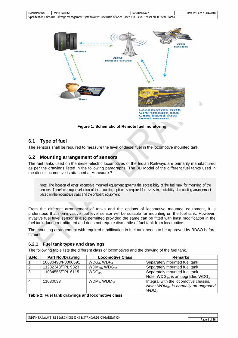
6 Functional requirements The fuel sensor system shall be designed to be fitted at suitable location on the locomotive fuel tank to measure the level of fuel in the tank and transmit the same along with time stamp, Loco no., and GPS data to the remote serverfor real time remote monitoring and GPS tracking.The system shall have a provision to set loco number in the device.
INDIAN RAILWAYS, RESEARCH DESIGNS & STANDARDS ORGANIZATION Page 5 of 16
Document No: MP.0.2400.63 Revision No:2 Date Issued: 23/04/2018 Specification Title: Anti Pilferage Management System (APMS) inclusive of GSM Based Fuel Level Sensor on IR Diesel Locos
Figure 1: Schematic of Remote fuel monitoring
6.1 Type of fuel The sensors shall be required to measure the level of diesel fuel in the locomotive mounted tank.
6.2 Mounting arrangement of sensors The fuel tanks used on the diesel-electric locomotives of the Indian Railways are primarily manufactured as per the drawings listed in the following paragraphs. The 3D Model of the different fuel tanks used in the diesel locomotive is attached at Annexure-7.
Note: The location of other locomotive mounted equipment governs the accessibility of the fuel tank for mounting of the sensors. Therefore proper selection of the mounting options is required for assessing suitability of mounting arrangement based on the locomotive class and the onboard equipment.
From the different arrangement of tanks and the options of locomotive mounted equipment, it is understood that non-invasive fuel level sensor will be suitable for mounting on the fuel tank. However, invasive fuel level sensor is also permitted provided the same can be fitted with least modification in the fuel tank during retrofitment and does not require dismantle of fuel tank from locomotive.
The mounting arrangement with required modification in fuel tank needs to be approved by RDSO before fitment.
6.2.1 Fuel tank types and drawings The following table lists the different class of locomotives and the drawing of the fuel tank.
S.No. Part No./Drawing Locomotive Class Remarks 1. 10630498/P0000591 WDG4, WDP4 Separately mounted fuel tank 2. 11232348/TPL 9323 WDM3D, WDG3D Separately mounted fuel tank 3. 11034555/TPL 6115 WDG3A Separately mounted fuel tank.
Note: WDG3A is an upgraded WDG2 4. 11030033 WDM2, WDM3A Integral with the locomotive chassis.
Note: WDM3A is normally an upgraded WDM2
Table 2: Fuel tank drawings and locomotive class
INDIAN RAILWAYS, RESEARCH DESIGNS & STANDARDS ORGANIZATION Page 6 of 16
Document No: MP.0.2400.63 Revision No:2 Date Issued: 23/04/2018 Specification Title: Anti Pilferage Management System (APMS) inclusive of GSM Based Fuel Level Sensor on IR Diesel Locos
Note: This table provides an indicative list. The correct tank type should be identified by physical examination of the locomotive.
6.2.1.1 Leakage proofing The entire assembly shall be leakage proof. Suitable gasket system shall be deployed to ensure that there is no fuel leakage from any joints.
6.2.2 Range of measurement The sensor shall be capable of measuring the fuel level from the top of the tank to the bottom. However, bottom 80 mm of the tank can be ignored, if required.However, software should consider the bottom ignored value as suitable offset value during display of fuel in litres.
6.3 Electrical interface The electrical interface of the sensors is described below. This requirement is applicable for both top and side mounted sensors.
6.3.1 Electrical power interface The system shall normally be powered from the locomotive 74V DC supply system. The voltage convertors, if any, required for fuel level sensor and its associated part shall be deemed to be a part of the supply.
The power supply requirements shall not exceed 12W per sensor under all operating conditions.
6.3.2 Signal Interface The interface system shall have provision of 2-wire 4-20mA scheme for parameter value transmission to MBCS/LCC.
The sensors shall provide a deterministic output of the fuel level in the tank as a current loop signal to the 4-20mA standard.
The fuel level sensor data shall be processed in the processor unit of the fuel level sensor. Processor unit will acquire data from fuel level sensor in litre, GPS module and store in their inbuilt memory and also send to server through GSM. The data transmission to remote server shall be based on TCP/IP protocol.
The interface document is given at Annexure-8.
Note: Minimum 256 MB non-volatile flash memory as on board user memory in Processor Unit of fuel level sensor for data logging on First in and First Out Basis and minimum 1 No. USB port complied to USB 2.0 specification for extracting data on board shall be provided.Suitable Application software shall be provided by the supplier.
6.4 Measurement requirements
6.4.1 Range The range of measurement shall be determined by the range of the fuel level as given in the table below. The sensor system can be designed to ignore the bottom 30mm of the range.
S.No. Part No./Drawing Locomotive Class Approximate Range of Measurement (Fuel Level)
Fuel volume in ltr.
1. 10630498/P0000591 WDG4, WDP4 860 mm 6000 2. 11232348/TPL 9323 WDM3D, WDG3D 955 mm 6000 3. 11034555/TPL 6115 WDG3A 955 mm 6000 4. 11030033 WDM2, WDM3A 1160 mm 5000 Table 3: Tank drawing and approximate range of measurement
INDIAN RAILWAYS, RESEARCH DESIGNS & STANDARDS ORGANIZATION Page 7 of 16
Document No: MP.0.2400.63 Revision No:2 Date Issued: 23/04/2018 Specification Title: Anti Pilferage Management System (APMS) inclusive of GSM Based Fuel Level Sensor on IR Diesel Locos 6.4.2 Resolution accuracy and precision The other qualifying parameters for the measurement shall be as given in the table below.
Parameter Value Remarks Resolution 50 ltrsor better Accuracy ±3% of full scale in fuel tank volume or
better
Precision ± 0.5% of the reading in fuel tank volume or better
Table 4: Resolution, accuracy and precision requirements
6.5 Ingress protection The supplied equipment,mounted on the outside of the locomotive cab, shall be rated for IP rating of IP67 to IEC60529.
The equipment mounted inside the locomotive cabin shall be compliance to IP65.
6.6 Impact Rating The supplied equipment, mounted shall be rated for IK rating of IK10 to IEC62262.
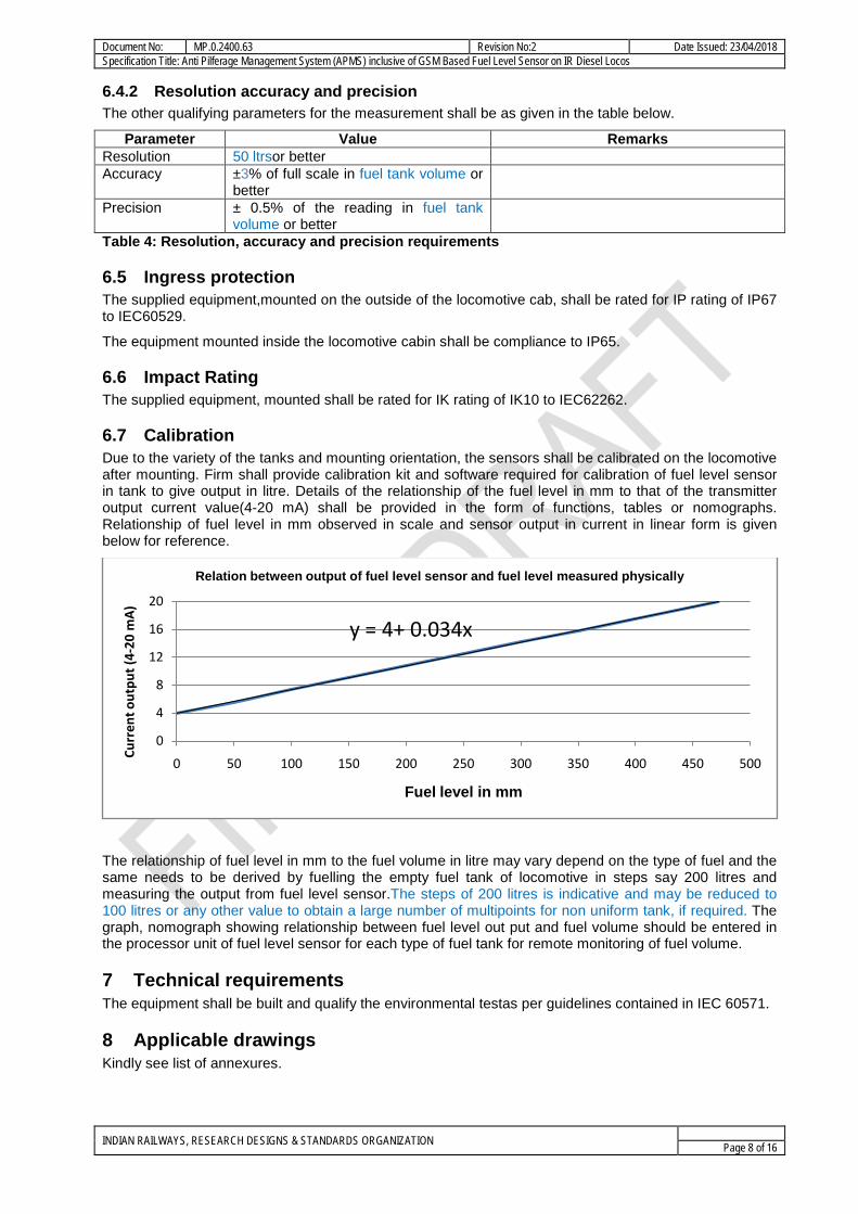
6.7 Calibration Due to the variety of the tanks and mounting orientation, the sensors shall be calibrated on the locomotive after mounting. Firm shall provide calibration kit and software required for calibration of fuel level sensor in tank to give output in litre. Details of the relationship of the fuel level in mm to that of the transmitter output current value(4-20 mA) shall be provided in the form of functions, tables or nomographs. Relationship of fuel level in mm observed in scale and sensor output in current in linear form is given below for reference.
The relationship of fuel level in mm to the fuel volume in litre may vary depend on the type of fuel and the same needs to be derived by fuelling the empty fuel tank of locomotive in steps say 200 litres and measuring the output from fuel level sensor.The steps of 200 litres is indicative and may be reduced to 100 litres or any other value to obtain a large number of multipoints for non uniform tank, if required. The graph, nomograph showing relationship between fuel level out put and fuel volume should be entered in the processor unit of fuel level sensor for each type of fuel tank for remote monitoring of fuel volume.
7 Technical requirements The equipment shall be built and qualify the environmental testas per guidelines contained in IEC 60571.
8 Applicable drawings Kindly see list of annexures.
y = 4+ 0.034x
0
4
8
12
16
20
0 50 100 150 200 250 300 350 400 450 500
Curr
ent o
utpu
t (4-
20 m
A)
Fuel level in mm
Relation between output of fuel level sensor and fuel level measured physically
INDIAN RAILWAYS, RESEARCH DESIGNS & STANDARDS ORGANIZATION Page 8 of 16
Document No: MP.0.2400.63 Revision No:2 Date Issued: 23/04/2018 Specification Title: Anti Pilferage Management System (APMS) inclusive of GSM Based Fuel Level Sensor on IR Diesel Locos
9 Safety requirements The installation, fitment and working of fuel level sensor on fuel tank should not cause any fire hazards.
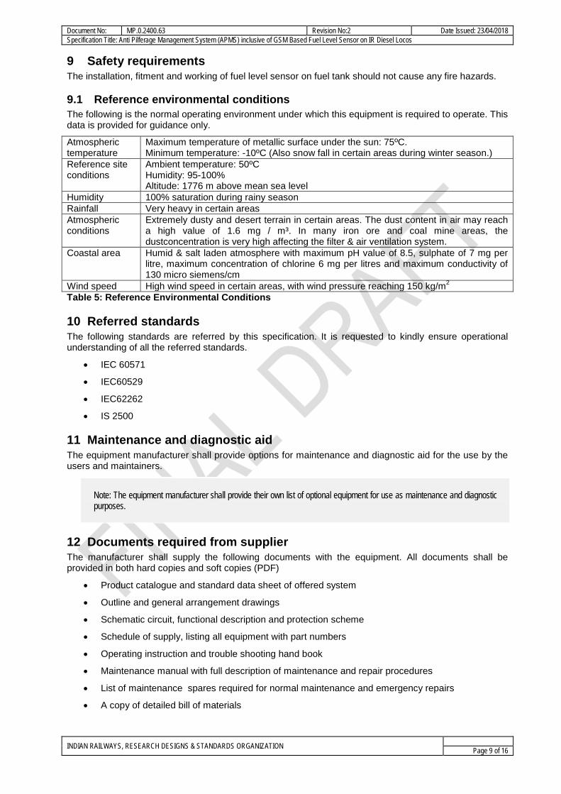
9.1 Reference environmental conditions The following is the normal operating environment under which this equipment is required to operate. This data is provided for guidance only.
Atmospheric temperature
Maximum temperature of metallic surface under the sun: 75ºC. Minimum temperature: -10ºC (Also snow fall in certain areas during winter season.)
Reference site conditions
Ambient temperature: 50ºC Humidity: 95-100% Altitude: 1776 m above mean sea level
Humidity 100% saturation during rainy season Rainfall Very heavy in certain areas Atmospheric conditions
Extremely dusty and desert terrain in certain areas. The dust content in air may reach a high value of 1.6 mg / m³. In many iron ore and coal mine areas, the dustconcentration is very high affecting the filter & air ventilation system.
Coastal area Humid & salt laden atmosphere with maximum pH value of 8.5, sulphate of 7 mg per litre, maximum concentration of chlorine 6 mg per litres and maximum conductivity of 130 micro siemens/cm
Wind speed High wind speed in certain areas, with wind pressure reaching 150 kg/m2 Table 5: Reference Environmental Conditions
10 Referred standards The following standards are referred by this specification. It is requested to kindly ensure operational understanding of all the referred standards.
• IEC 60571
• IEC60529
• IEC62262
• IS 2500
11 Maintenance and diagnostic aid The equipment manufacturer shall provide options for maintenance and diagnostic aid for the use by the users and maintainers.
Note: The equipment manufacturer shall provide their own list of optional equipment for use as maintenance and diagnostic purposes.
12 Documents required from supplier The manufacturer shall supply the following documents with the equipment. All documents shall be provided in both hard copies and soft copies (PDF)
• Product catalogue and standard data sheet of offered system
• Outline and general arrangement drawings
• Schematic circuit, functional description and protection scheme
• Schedule of supply, listing all equipment with part numbers
• Operating instruction and trouble shooting hand book
• Maintenance manual with full description of maintenance and repair procedures
• List of maintenance spares required for normal maintenance and emergency repairs
• A copy of detailed bill of materials
INDIAN RAILWAYS, RESEARCH DESIGNS & STANDARDS ORGANIZATION Page 9 of 16
Document No: MP.0.2400.63 Revision No:2 Date Issued: 23/04/2018 Specification Title: Anti Pilferage Management System (APMS) inclusive of GSM Based Fuel Level Sensor on IR Diesel Locos
• Recommended list of spares with cost for 3 years maintenance after warranty
• Test protocol with procedure of testing
• Details of technical support and training offered
• Detailed calibration procedure
13 Warranty The manufacturer shall provide warranty as per IRS terms and conditions.
14 Tests & Verification The equipment shall be tested for functional capability, ability to withstand environmental conditions and for reliable performance under field conditions.
14.1 Test standards to be indicated The equipment shall be tested for compliance to the requirements set forth in this document. These tests shall comprise of the following:
• Functional tests, for determining that the equipment complies with the requirements of this specification.
• Environmental tests shall be conducted as specified under the respective clauses
14.2 Sampling plan Sampling shall be done as per IS2500 wherever not specified but required. Sampling shall be done as per the requirements wherever specified in this document. If the specific contract includes specific clause for sampling, the same shall be applicable.
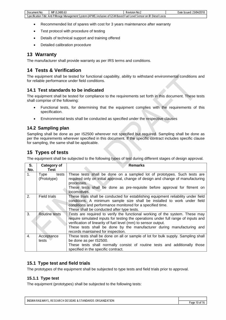
15 Types of tests The equipment shall be subjected to the following types of test during different stages of design approval.
S. No.
Category of Test
Remarks
1. Type tests (Prototype)
These tests shall be done on a sampled lot of prototypes. Such tests are required only on initial approval, change of design and change of manufacturing processes. These tests shall be done as pre-requisite before approval for fitment on locomotives.
2. Field trials These trials shall be conducted for establishing equipment reliability under field conditions. A minimum sample size shall be installed to work under field conditions and performance monitored for a specified time. These shall be conducted after type tests.
3. Routine tests Tests are required to verify the functional working of the system. These may require simulated inputs for testing the operations under full range of inputs and verification of linearity of fuel level (mm) to sensor output. These tests shall be done by the manufacturer during manufacturing and records maintained for inspection.
4. Acceptance tests
These tests shall be done on all or sample of lot for bulk supply. Sampling shall be done as per IS2500. These tests shall normally consist of routine tests and additionally those specified in the specific contract.
15.1 Type test and field trials The prototypes of the equipment shall be subjected to type tests and field trials prior to approval.
15.1.1 Type test The equipment (prototypes) shall be subjected to the following tests:
INDIAN RAILWAYS, RESEARCH DESIGNS & STANDARDS ORGANIZATION Page 10 of 16
Document No: MP.0.2400.63 Revision No:2 Date Issued: 23/04/2018 Specification Title: Anti Pilferage Management System (APMS) inclusive of GSM Based Fuel Level Sensor on IR Diesel Locos
• The environmental, EMI/EMC/RFI tests shall be conducted at any reputed agency having required facilities to do so.
• Testing for IP / IK rating of the equipment, shall be conducted at any reputed testing agency having required facilities to do so.
• The functional tests for compliance to requirements of this document shall be witnessed by RDSO.
Note:
1. RDSO shall be apprised and approval taken for testing of the equipment at any specific testing agency prior to the tests.
2. Incase the equipment has been tested for compliance to other standards, details should be provided in form of traceable certificates issued by the testing / certification bodies. The test so certified shall be used to reduce the number of tests required for approval.
15.1.2 Field trial Atleast one loco set of equipment (or as decided by IR) shall be subjected to field trials for six (6) months before clearance is given for bulk supply. During this period, the performance of the equipment shall be closely monitored and evaluated by RDSO. These trials are intended to prove
• Reliability under rigorous environmental and operating conditions
• Advantages for locomotive operation and maintenance
• Maintainability of the equipment.
If modifications found necessary as a result of the tests, the supplier at his own cost shall carry out trials after the relevant modifications have been approved by RDSO.
15.2 Routine test Routine tests shall be conducted by the equipment manufacturer as per their quality assurance plan (QAP) which shall be offered to RDSO for approval.
15.3 Acceptance test These tests shall be conducted on equipment when supplied in bulk. The equipment lot shall be sampled as per IS2500 or as specified in the purchase order.
The acceptance test shall include:
• Verification of equipment conformance by checking of type test reports, manufacturers certificates for outsourced components.
• Functional tests of the equipment including verification of linearity of fuel level (mm) to sensor output
• Any other test as required by the purchase contract
15.4 Makers test certificate for outsourced item All items that are outsourced by the equipment manufacturer shall be indicated so. The type and extent of control that has been exercised shall be provided with proper documentation.
The manufacturers (of the outsourced sub-assembly) test certificates shall be provided.
16 Painting, labeling and marking The equipment shall be appropriately painted for operational use, aesthetics and protection. The parts, connector ports, mounting points etc. shall be clearly marked in a manner that these are easily readable and remain legible over the lifetime of the equipment.
ID plate Name of Component, Make, Sl. No, Date of Manufacture, Ratings shall be provided on all assemblies/subassemblies.
INDIAN RAILWAYS, RESEARCH DESIGNS & STANDARDS ORGANIZATION Page 11 of 16
Document No: MP.0.2400.63 Revision No:2 Date Issued: 23/04/2018 Specification Title: Anti Pilferage Management System (APMS) inclusive of GSM Based Fuel Level Sensor on IR Diesel Locos
17 Packaging and delivery/shipment The equipment consists of sensitive and fragile electronic systems. These should be packed with precautions required to prevent damage in transit.
All requirements of IRS conditions for packaging and delivery shall be applicable.
18 IPR disclaimer pin pointing responsibility for violation if any on supplier
18.1 Undertaking by equipment manufacturer All the specifications issued by RDSO shall include a requirement of undertaking to be signed by Vendors on “INFRINGEMENT OF PATENT RIGHTS”. The undertaking can be as under
Indian Railways shall not be responsible for infringement of patent rights arising due to similarity in design, manufacturing process, use of similar components in the design & development of this item and any other factor not mentioned herein which may cause such a dispute. The entire responsibility to settle any such disputes/matters lies with the manufacturer/ supplier.
Details / design/documents given by them are not infringing any IPR and they are responsible in absolute and full measure instead of railways for any such violations. Data, specifications and other IP as generated out of interaction with railways shall not be unilaterally used without the consent of RDSO and right of Railways / RDSO on such IP is acceptable to them.
18.2 Declaration of confidentiality of submitted documents by manufacturers While submitting a new proposal/design, manufacturer must classify their documents confidentialitydeclaration, such as
This document and its contents are the property of M/s XYZ (Name of the vendor) or its subsidiaries. This document contains confidential proprietary information. The reproduction, distribution, utilization or the communication of this document or any part thereof, without express authorization is strictly prohibited. Offenders will be held liable for the payment of damages. Indian Railways/RDSO is granted right to use, copy and distribute this document for the use of inspection, operation, maintenance and repair etc.
INDIAN RAILWAYS, RESEARCH DESIGNS & STANDARDS ORGANIZATION Page 12 of 16
Document No: MP.0.2400.63 Revision No:2 Date Issued: 23/04/2018 Specification Title: Anti Pilferage Management System (APMS) inclusive of GSM Based Fuel Level Sensor on IR Diesel Locos
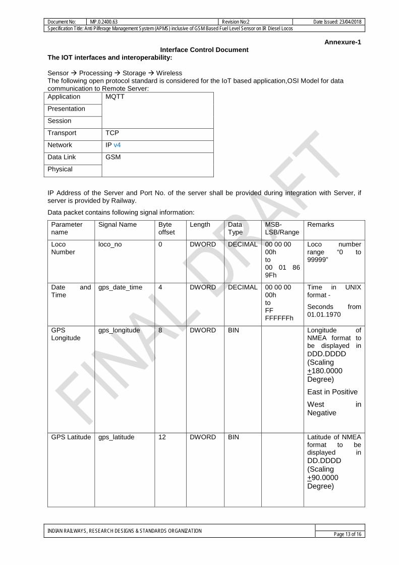
Annexure-1 Interface Control Document
The IOT interfaces and interoperability: Sensor Processing Storage Wireless The following open protocol standard is considered for the IoT based application,OSI Model for data communication to Remote Server: Application MQTT
Presentation
Session
Transport TCP
Network IP v4
Data Link GSM
Physical
IP Address of the Server and Port No. of the server shall be provided during integration with Server, if server is provided by Railway.
Data packet contains following signal information:
Parameter name
Signal Name Byte offset
Length Data Type
MSB-LSB/Range
Remarks
Loco Number
loco_no 0 DWORD DECIMAL 00 00 00 00h to 00 01 86 9Fh
Loco number range “0 to 99999”
Date and Time
gps_date_time 4 DWORD DECIMAL 00 00 00 00h to FF FFFFFFh
Time in UNIX format -
Seconds from 01.01.1970
GPS Longitude
gps_longitude 8 DWORD BIN Longitude of NMEA format to be displayed in DDD.DDDD (Scaling +180.0000 Degree)
East in Positive
West in Negative
GPS Latitude gps_latitude 12 DWORD BIN Latitude of NMEA format to be displayed in DD.DDDD (Scaling +90.0000 Degree)
INDIAN RAILWAYS, RESEARCH DESIGNS & STANDARDS ORGANIZATION Page 13 of 16
Document No: MP.0.2400.63 Revision No:2 Date Issued: 23/04/2018 Specification Title: Anti Pilferage Management System (APMS) inclusive of GSM Based Fuel Level Sensor on IR Diesel Locos
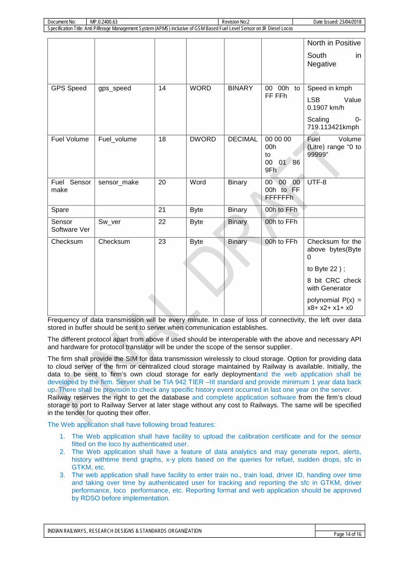
North in Positive
South in Negative
GPS Speed gps_speed 14 WORD BINARY 00 00h to FF FFh
Speed in kmph
LSB Value 0.1907 km/h
Scaling 0-719.113421kmph
Fuel Volume Fuel_volume 18 DWORD DECIMAL 00 00 00 00h to 00 01 86 9Fh
Fuel Volume (Litre) range “0 to 99999”
Fuel Sensor make
sensor_make 20 Word Binary 00 00 00 00h to FF FFFFFFh
UTF-8
Spare 21 Byte Binary 00h to FFh
Sensor Software Ver
Sw_ver 22 Byte Binary 00h to FFh
Checksum Checksum 23 Byte Binary 00h to FFh Checksum for the above bytes(Byte 0
to Byte 22 ) ;
8 bit CRC check with Generator
polynomial P(x) = x8+ x2+ x1+ x0
Frequency of data transmission will be every minute. In case of loss of connectivity, the left over data stored in buffer should be sent to server when communication establishes.
The different protocol apart from above if used should be interoperable with the above and necessary API and hardware for protocol translator will be under the scope of the sensor supplier.
The firm shall provide the SIM for data transmission wirelessly to cloud storage. Option for providing data to cloud server of the firm or centralized cloud storage maintained by Railway is available. Initially, the data to be sent to firm’s own cloud storage for early deploymentand the web application shall be developed by the firm. Server shall be TIA 942 TIER –III standard and provide minimum 1 year data back up. There shall be provision to check any specific history event occurred in last one year on the server. Railway reserves the right to get the database and complete application software from the firm’s cloud storage to port to Railway Server at later stage without any cost to Railways. The same will be specified in the tender for quoting their offer.
The Web application shall have following broad features:
1. The Web application shall have facility to upload the calibration certificate and for the sensor fitted on the loco by authenticated user.
2. The Web application shall have a feature of data analytics and may generate report, alerts, history withtime trend graphs, x-y plots based on the queries for refuel, sudden drops, sfc in GTKM, etc.
3. The web application shall have facility to enter train no., train load, driver ID, handing over time and taking over time by authenticated user for tracking and reporting the sfc in GTKM, driver performance, loco performance, etc. Reporting format and web application should be approved by RDSO before implementation.
INDIAN RAILWAYS, RESEARCH DESIGNS & STANDARDS ORGANIZATION Page 14 of 16

Document No: MP.0.2400.63 Revision No:2 Date Issued: 23/04/2018 Specification Title: Anti Pilferage Management System (APMS) inclusive of GSM Based Fuel Level Sensor on IR Diesel Locos
4. Web application shall display the location of the loco on the map based on GPS data similarto standard GPS tracking system.
5. Server and Web applications shall be able to generate SMS alerts and send emails to the defined users.
INDIAN RAILWAYS, RESEARCH DESIGNS & STANDARDS ORGANIZATION Page 15 of 16
Document No: MP.0.2400.63 Revision No:2 Date Issued: 23/04/2018 Specification Title: Anti Pilferage Management System (APMS) inclusive of GSM Based Fuel Level Sensor on IR Diesel Locos
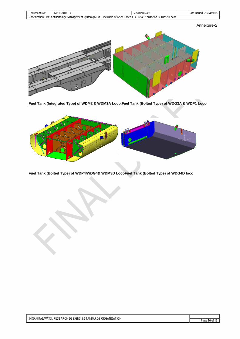
Annexure-2
Fuel Tank (Integrated Type) of WDM2 & WDM3A Loco.Fuel Tank (Bolted Type) of WDG3A & WDP1 Loco
Fuel Tank (Bolted Type) of WDP4/WDG4& WDM3D LocoFuel Tank (Bolted Type) of WDG4D loco
INDIAN RAILWAYS, RESEARCH DESIGNS & STANDARDS ORGANIZATION Page 16 of 16
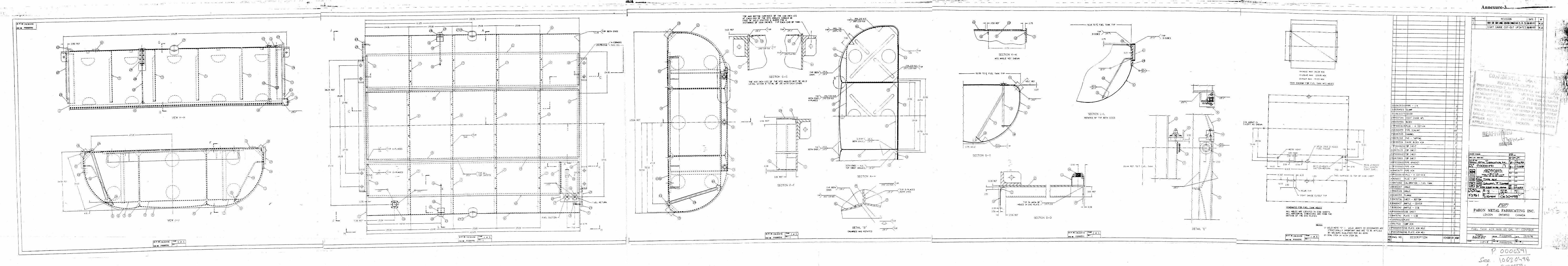
Annexure-3
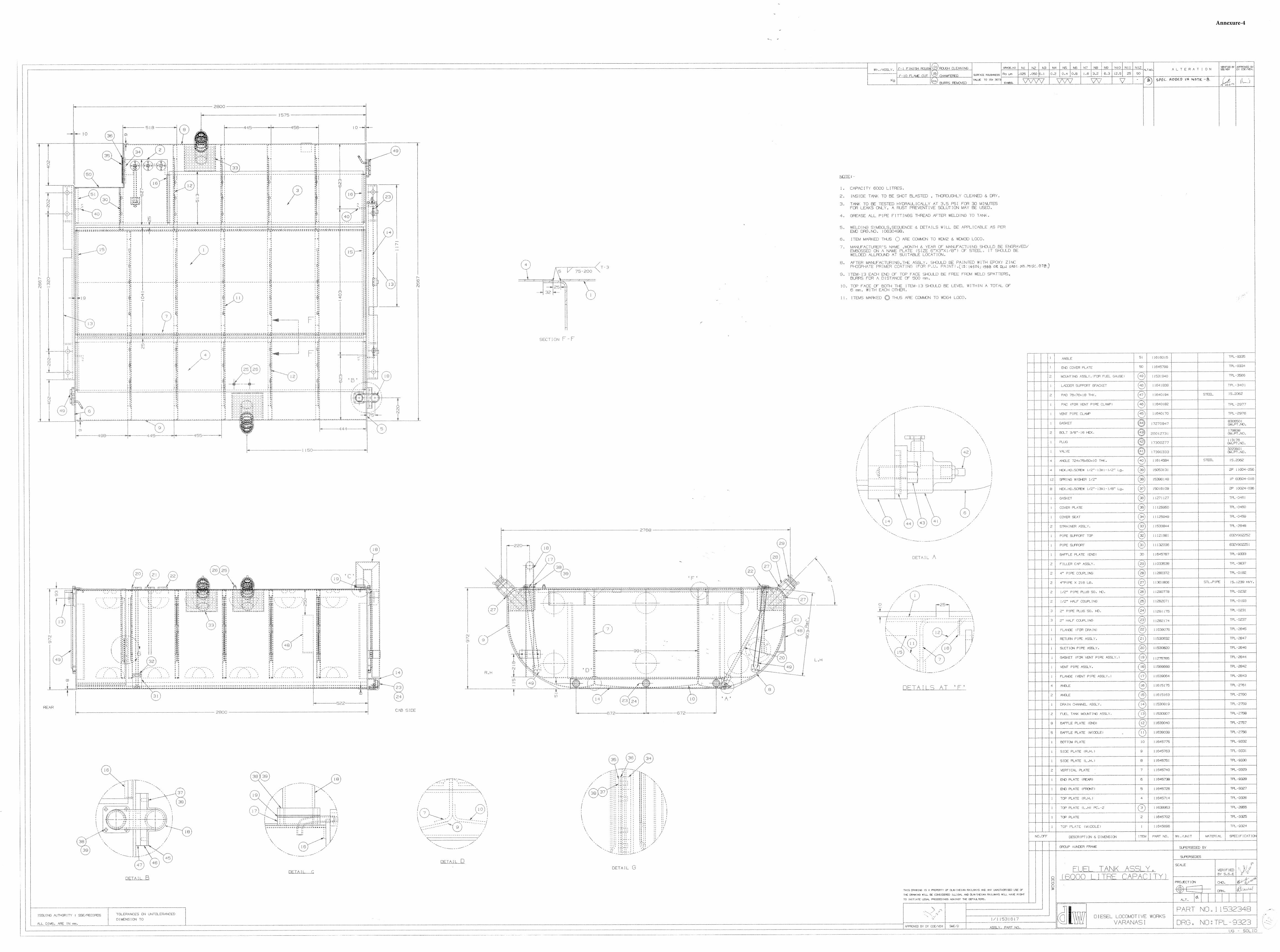
Annexure-4
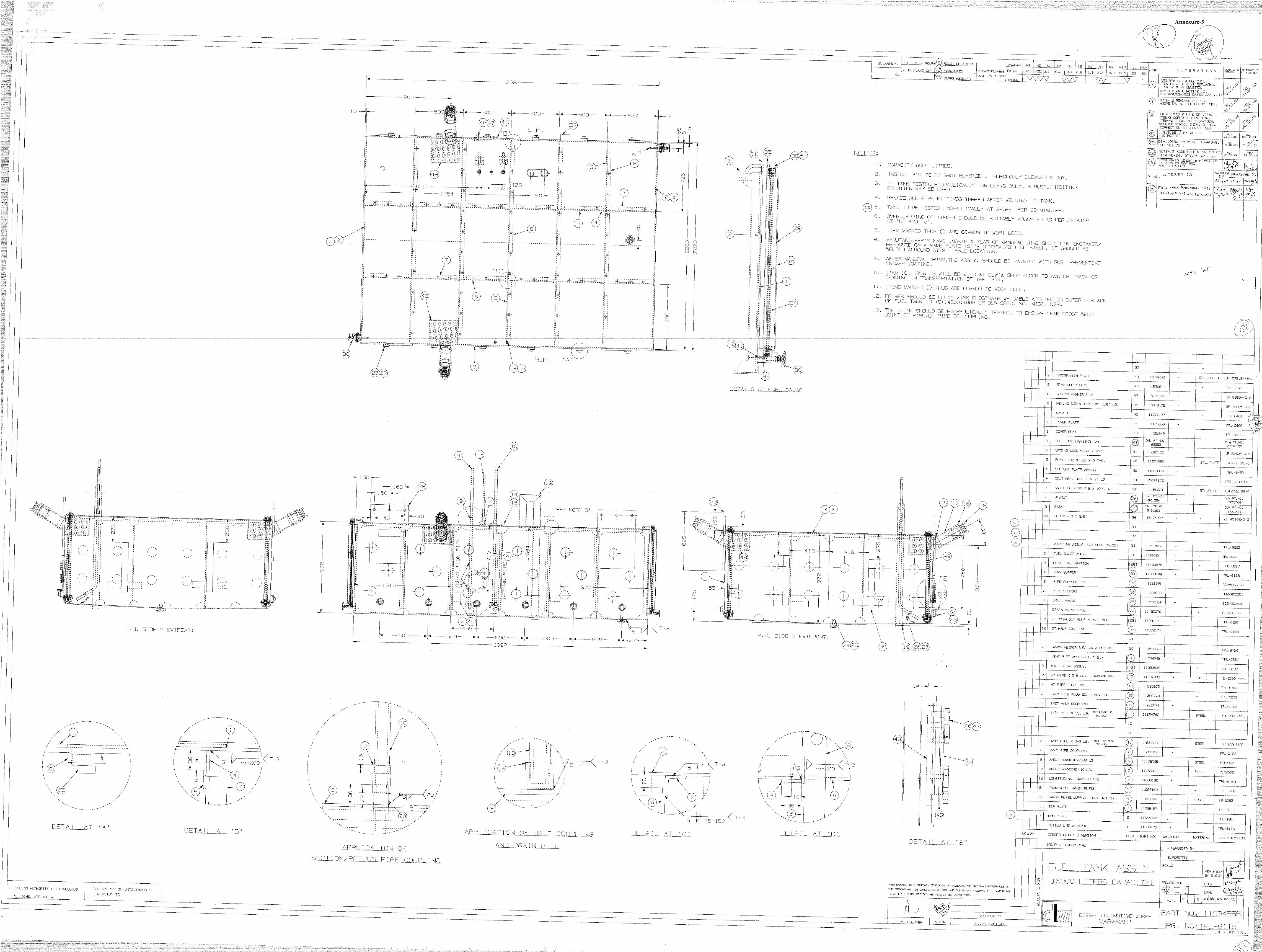
Annexure-5
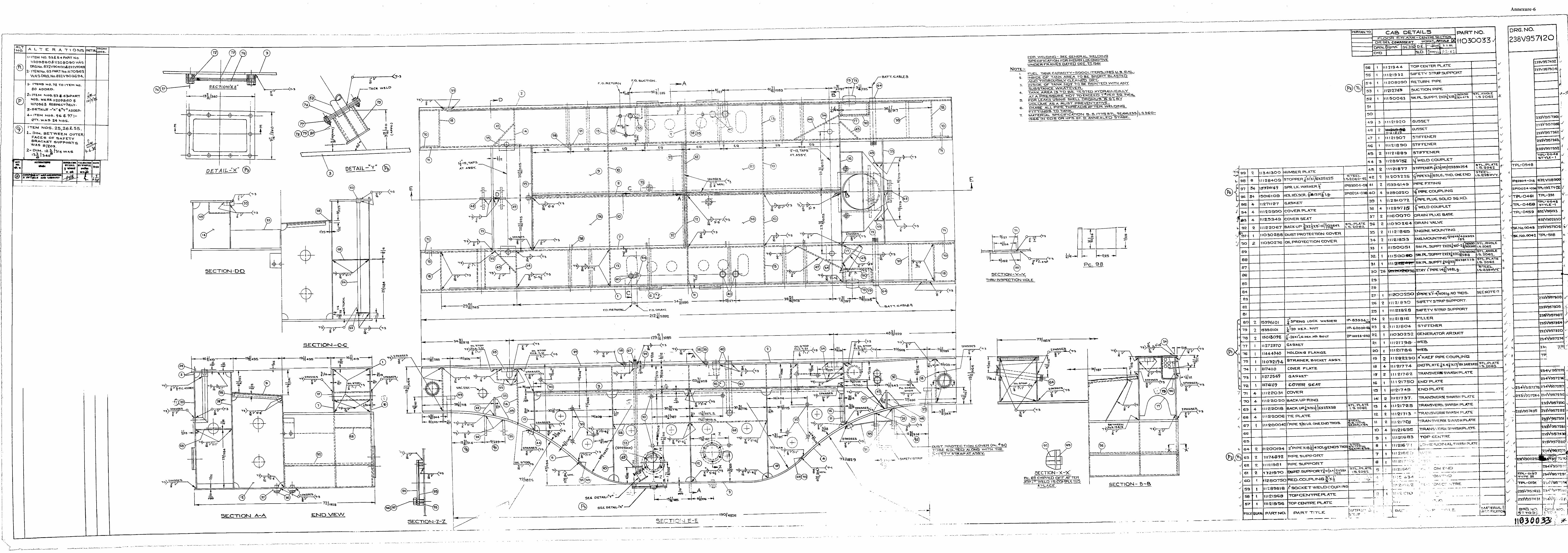
Annexure-6
Annexure-7
Related Documents