DO TREE BELTS INCREASE RISK OF EXPLOSION FOR LPG SPHERES? Gustavo F. Santiago UFRGS Mechanical Engineering Post-graduation Program – PROMEC [email protected] César A. Leal UFRGS Mechanical Engineering Post-graduation Program – PROMEC and UFRGS Nuclear Engineering Department - DENUC [email protected] Abstract. In this work we used the Multi-Energy method to estimate the overpressure and the positive phase duration as a function of the distance from the explosion center, resulting from Vapor Cloud Explosions of LPG-air mixtures in highly congested areas near an LPG storage park. Simulations were made for square shaped zones planted with 10 m high trees and areas ranging from 50,000 m 2 to 250,000 m 2 . The criterion used to evaluate the risk to a LPG storage sphere was the stress failure of the diagonal arm braces supporting it. The explosion effects were studied for a 14.5 m diameter LPG storage sphere, located at distances ranging from 10 m to 100 m away from the border of the congested area. It is shown that congested areas of at least 100,000 m 2 can pose a risk to the LPG spheres with minimal filling. It is possible to conclude that it is better to keep a smaller number of full filled spheres than many spheres with less filling of LPG. We estimated for congested areas with 25 % blockage ratio that the minimum safe distance, measured from the border of the tree grove to the sphere, varies from 10 m, for 100,000 m 2 areas, to 87.6 m, for 250,000 m 2 areas. The tree spacing influence represented by the blockage ratio was also analyzed, showing it affects the sphere minimum safe distance. Finally, recommendations are made regarding the minimum safe distance between the spheres and the congested area, which seems to have a maximum value, as well as other ways to lessen the risk represented by explosions, but further conclusions would require a different approach as the loading would be Dynamic instead of Impulsive for tree belts with areas bigger than 250,000 m 2 . Keywords. explosion, effects, LPG, VCE , congested areas, tree belts, and sphere failure. 1. Introduction The study of accidents caused by the release of flammable liquids and gases, particularly Vapor Cloud Explosions (VCE), has been increasingly done in the last decades. Identification of possible causes of this kind of accident, as well as evaluating its consequences, are valuable tools to minimize and possibly avoid its occurrence and undesirable results. There was a noticeable advance in its mechanisms and phenomena comprehension, as well as significant improvement of the effects evaluation methods in this period. Institutions like Christian Michelsen Research (CMR) and Prins Mauritz Laboratory (TNO)[1] have taken lead in the development of computational codes and evaluation methods to be used directly by the most affected branches of flammable gas and liquid production, storage and processing industries, on and off-shore. This fruitful collaboration between private initiative and research institutions devoted to the development of simulation tools, has proved itself of great value to lessen the involved risks and increase security of such industrial plants. In this work the proper management of groves and tree belts around petrochemical plants will be evaluated, showing that their use, ignoring fire risk standards, can help toxic and flammable products dispersion but also increase their burning rate, leading to explosion. A hypothetical case analysis done over a tree grove to show that its presence can be a risk factor to the nearby plants and population. To evaluate partially obstructed Vapor Cloud Explosions the Multi-Energy method was used as the resulting overpressure prediction tool, structural analysis was made using a finite element simulation program (ANSYS) to evaluate the natural period of oscillation of the structure, followed by the interaction of the blast wave generated by the explosion with a spherical tank of LPG. 1.1. Scenario Description and Assumed Hypothesis The scenario used in this VCE explosion evaluation is a LPG storage steel sphere close to a tree grove. The explosion calculations are made as stoichiometric propane-air reactions, because propane is the main gas in LPG composition. In order for this scenario be representative of a reasonable number of similar situations, the sphere dimensions was chosen to be close to those found in refineries and most medium and large petrochemical plants. LPG storage parks are usually composed of a group of spheres connected to the refining, bottling or processing plant by a series of pipes. This site is usually unobstructed and easily accessible in case of fire combat. Such areas are not usually seen as possible explosion scenarios, although flash fires could occur. Usually, tree belts around industrial plants help the process of gas dispersion in the atmosphere by increasing the surface roughness length, and thus atmospheric turbulence. The tree grove can also be a possible risk to the LPG storage spheres. This possibility arises because of the capability of inducing turbulence in the flow of gas inside the tree grove. With greater induced turbulence, explosions could be generated in a fire inside the grove instead of flash fire [2,3]. The induced

Welcome message from author
This document is posted to help you gain knowledge. Please leave a comment to let me know what you think about it! Share it to your friends and learn new things together.
Transcript
DO TREE BELTS INCREASE RISK OF EXPLOSION FOR LPG SPHERES? Gustavo F. Santiago UFRGS Mechanical Engineering Post-graduation Program – PROMEC
César A. Leal UFRGS Mechanical Engineering Post-graduation Program – PROMEC and UFRGS Nuclear Engineering Department - DENUC
Abstract. In this work we used the Multi-Energy method to estimate the overpressure and the positive phase duration as a function of the
distance from the explosion center, resulting from Vapor Cloud Explosions of LPG-air mixtures in highly congested areas near an LPG
storage park. Simulations were made for square shaped zones planted with 10 m high trees and areas ranging from 50,000 m2 to 250,000
m2. The criterion used to evaluate the risk to a LPG storage sphere was the stress failure of the diagonal arm braces supporting it. The
explosion effects were studied for a 14.5 m diameter LPG storage sphere, located at distances ranging from 10 m to 100 m away from the
border of the congested area. It is shown that congested areas of at least 100,000 m2 can pose a risk to the LPG spheres with minimal
filling. It is possible to conclude that it is better to keep a smaller number of full filled spheres than many spheres with less filling of LPG.
We estimated for congested areas with 25 % blockage ratio that the minimum safe distance, measured from the border of the tree grove to
the sphere, varies from 10 m, for 100,000 m2 areas, to 87.6 m, for 250,000 m2 areas. The tree spacing influence represented by the
blockage ratio was also analyzed, showing it affects the sphere minimum safe distance. Finally, recommendations are made regarding the
minimum safe distance between the spheres and the congested area, which seems to have a maximum value, as well as other ways to
lessen the risk represented by explosions, but further conclusions would require a different approach as the loading would be Dynamic
instead of Impulsive for tree belts with areas bigger than 250,000 m2.
Keywords. explosion, effects, LPG, VCE , congested areas, tree belts, and sphere failure.
1. Introduction
The study of accidents caused by the release of flammable liquids and gases, particularly Vapor Cloud Explosions
(VCE), has been increasingly done in the last decades. Identification of possible causes of this kind of accident, as well as
evaluating its consequences, are valuable tools to minimize and possibly avoid its occurrence and undesirable results. There
was a noticeable advance in its mechanisms and phenomena comprehension, as well as significant improvement of the
effects evaluation methods in this period. Institutions like Christian Michelsen Research (CMR) and Prins Mauritz
Laboratory (TNO)[1] have taken lead in the development of computational codes and evaluation methods to be used
directly by the most affected branches of flammable gas and liquid production, storage and processing industries, on and
off-shore. This fruitful collaboration between private initiative and research institutions devoted to the development of
simulation tools, has proved itself of great value to lessen the involved risks and increase security of such industrial plants.
In this work the proper management of groves and tree belts around petrochemical plants will be evaluated, showing that
their use, ignoring fire risk standards, can help toxic and flammable products dispersion but also increase their burning rate,
leading to explosion. A hypothetical case analysis done over a tree grove to show that its presence can be a risk factor to the
nearby plants and population. To evaluate partially obstructed Vapor Cloud Explosions the Multi-Energy method was used
as the resulting overpressure prediction tool, structural analysis was made using a finite element simulation program
(ANSYS) to evaluate the natural period of oscillation of the structure, followed by the interaction of the blast wave
generated by the explosion with a spherical tank of LPG.
1.1. Scenario Description and Assumed Hypothesis
The scenario used in this VCE explosion evaluation is a LPG storage steel sphere close to a tree grove. The explosion
calculations are made as stoichiometric propane-air reactions, because propane is the main gas in LPG composition.
In order for this scenario be representative of a reasonable number of similar situations, the sphere dimensions was
chosen to be close to those found in refineries and most medium and large petrochemical plants.
LPG storage parks are usually composed of a group of spheres connected to the refining, bottling or processing plant by
a series of pipes. This site is usually unobstructed and easily accessible in case of fire combat. Such areas are not usually
seen as possible explosion scenarios, although flash fires could occur.
Usually, tree belts around industrial plants help the process of gas dispersion in the atmosphere by increasing the
surface roughness length, and thus atmospheric turbulence. The tree grove can also be a possible risk to the LPG storage
spheres. This possibility arises because of the capability of inducing turbulence in the flow of gas inside the tree grove. With
greater induced turbulence, explosions could be generated in a fire inside the grove instead of flash fire [2,3]. The induced
turbulence is a function of obstacle dimensions and spacing, sometimes characterized by the blockage ratio (β) of the site
cross section [4, 5].
Equally important in this evaluation are the total volume of the grove and the distance from its border to the spheres.
The main dimensions of the grove and its location relative to the sphere that could lead to a potential risk will be
determined here, as well as the possible measures that could be taken in order to minimize this risk.
The scenario that will be analyzed is an accidental release of LPG with formation of a flammable cloud of LPG-air
inside a grove of Eucalyptus trees, followed by an explosion with generation of a blast wave, which would interact with a
storage sphere. The aim of the paper is to establish the conditions that would lead to the collapse of the structure that
supports the tank, with a consequent increase in the seriousness of the accident.
1.2. LPG Sphere
The LPG storage sphere and its supporting columns used in this study are made of welded steel plates, submitted to
thermal stress release treatment before its use. The support columns are connected by diagonal bracing arms as structural
reinforcement. Each column is fixed to the ground by only two bolts, allowing it to rotate around an axis perpendicular to
the bolts, which can be considered as an articulated joint.
Basically the maximum expected wind force is used as the highest horizontal loading forces on this kind of structure,
which justifies its scarce column ground fixing and small bracing arm dimensions.
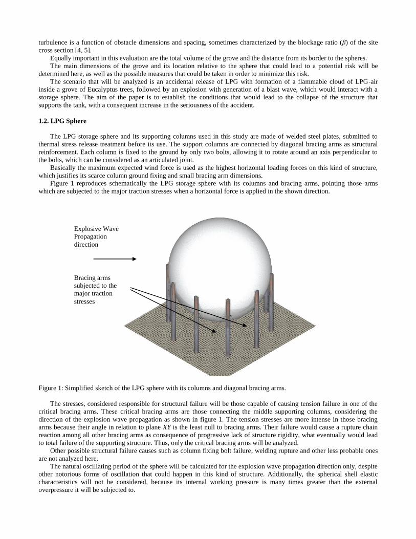
Figure 1 reproduces schematically the LPG storage sphere with its columns and bracing arms, pointing those arms
which are subjected to the major traction stresses when a horizontal force is applied in the shown direction.
Figure 1: Simplified sketch of the LPG sphere with its columns and diagonal bracing arms.
The stresses, considered responsible for structural failure will be those capable of causing tension failure in one of the
critical bracing arms. These critical bracing arms are those connecting the middle supporting columns, considering the
direction of the explosion wave propagation as shown in figure 1. The tension stresses are more intense in those bracing
arms because their angle in relation to plane XY is the least null to bracing arms. Their failure would cause a rupture chain
reaction among all other bracing arms as consequence of progressive lack of structure rigidity, what eventually would lead
to total failure of the supporting structure. Thus, only the critical bracing arms will be analyzed.
Other possible structural failure causes such as column fixing bolt failure, welding rupture and other less probable ones
are not analyzed here.
The natural oscillating period of the sphere will be calculated for the explosion wave propagation direction only, despite
other notorious forms of oscillation that could happen in this kind of structure. Additionally, the spherical shell elastic
characteristics will not be considered, because its internal working pressure is many times greater than the external
overpressure it will be subjected to.
Bracing arms
subjected to the
major traction
stresses
Explosive Wave
Propagation
direction
The simplifications above stated are based on the most probable failure cause found in the literature [6] and in structural
models using precision compatible with the Multi-Energy method [7].
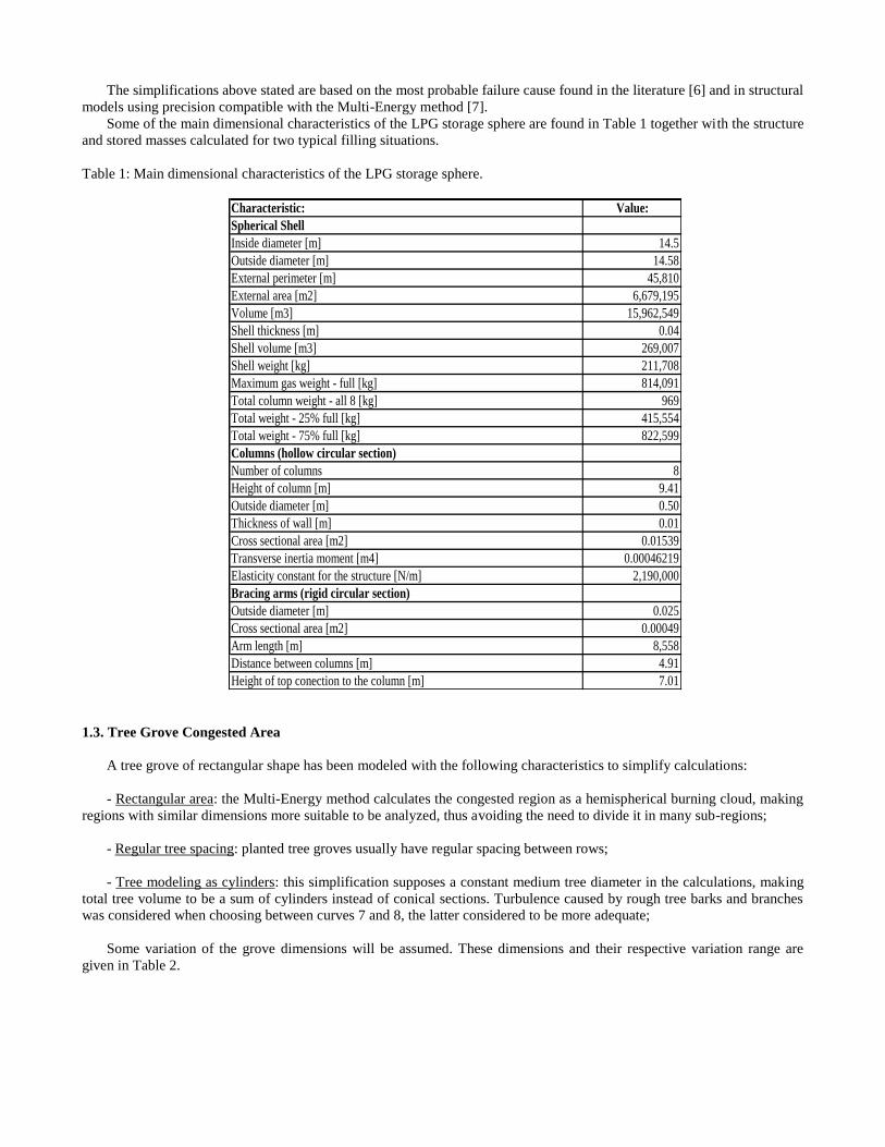
Some of the main dimensional characteristics of the LPG storage sphere are found in Table 1 together with the structure
and stored masses calculated for two typical filling situations.
Table 1: Main dimensional characteristics of the LPG storage sphere.
Characteristic: Value:
Spherical Shell
Inside diameter [m] 14.5
Outside diameter [m] 14.58
External perimeter [m] 45,810
External area [m2] 6,679,195
Volume [m3] 15,962,549
Shell thickness [m] 0.04
Shell volume [m3] 269,007
Shell weight [kg] 211,708
Maximum gas weight - full [kg] 814,091
Total column weight - all 8 [kg] 969
Total weight - 25% full [kg] 415,554
Total weight - 75% full [kg] 822,599
Columns (hollow circular section)
Number of columns 8
Height of column [m] 9.41
Outside diameter [m] 0.50
Thickness of wall [m] 0.01
Cross sectional area [m2] 0.01539
Transverse inertia moment [m4] 0.00046219
Elasticity constant for the structure [N/m] 2,190,000
Bracing arms (rigid circular section)
Outside diameter [m] 0.025
Cross sectional area [m2] 0.00049
Arm length [m] 8,558
Distance between columns [m] 4.91
Height of top conection to the column [m] 7.01
1.3. Tree Grove Congested Area
A tree grove of rectangular shape has been modeled with the following characteristics to simplify calculations:
- Rectangular area: the Multi-Energy method calculates the congested region as a hemispherical burning cloud, making
regions with similar dimensions more suitable to be analyzed, thus avoiding the need to divide it in many sub-regions;
- Regular tree spacing: planted tree groves usually have regular spacing between rows;
- Tree modeling as cylinders: this simplification supposes a constant medium tree diameter in the calculations, making
total tree volume to be a sum of cylinders instead of conical sections. Turbulence caused by rough tree barks and branches
was considered when choosing between curves 7 and 8, the latter considered to be more adequate;
Some variation of the grove dimensions will be assumed. These dimensions and their respective variation range are
given in Table 2.
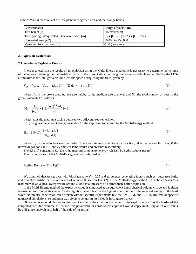
Table 2: Main dimensions of the tree planted congested area and their range bands.
Caracteristic: Range of variation:
Tree height [m] 10 (maximum)
Tree spacing (w/equivalent Blockage Ratio) [m] 1.2 ( β=0.25 ) to 2.4 ( β=0.125 )
Congested area [m2] 50,000 to 250,000
Maximum tree diameter [m] 0.30 (constant)
2. Explosion Evaluation
2.1. Available Explosion Energy
In order to estimate the results of an explosion using the Multi-Energy method, it is necessary to determine the volume
of the region containing the flammable mixture. In the present situation, the grove volume available to be filled by the LPG-
air mixture is the total grove volume less the space occupied by the trees, given by:
Vgas = Vgrove – Vtrees = (Ah . ha) – [( da 2 / 4 ) ha . Na] (1)
where Ah is the grove area, ha the tree height, da the medium tree diameter and Na the total number of trees in the
grove, calculated as follows:
0.5
h aha 2
a a
(A ) -dAN = +{[2. ]+1}
(e ) e (2)
where ea is the medium spacing between two adjacent tree centerlines.
Eq. (3) - gives the amount energy available for the explosion to be used by the Multi-Energy method:
6 0 0Q
gás 0
(1+5.n ).R.TE = 3.5x10 .
m .M.P (3)
where n0 is the ratio between the moles of gas and air in a stoichiometric reaction, M is the gas molar mass, R the
universal gas constant, T0 and P0 ambient temperature and pressure respectively.
The 3.5x10⁶ constant in Eq. (3) is the medium combustion energy released by hydrocarbons per m
3.
The scaling factor of the Multi-Energy method is defined as:
Scaling Factor = (EQ / P0)1/3
(4)
We assumed that tree groves with blockage ratio β > 0.25 and turbulence generating factors such as rough tree barks
and branches justify the use of curves of number 8, seen in Fig. (2), of the Multi-Energy method. This choice leads to a
maximum relative peak overpressure around 2, or a total pressure of 3 atmospheres after explosion.
In the Multi-Energy method the explosive cloud is simulated as an equivalent hemispherical volume charge and ignition
is assumed to occur at its center. Central ignition would lead to the highest contribution of the released energy to the blast
wave. No precise conclusion can be taken without specific experiments like the EMERGE and BFETS [8] tests or specific
numerical simulations, so attention was given to central ignited clouds in congested areas.
Of course, one could choose another point inside of the cloud as the center of the explosion, such as the border of the
congested area, for example. Of course, this pessimistic or conservative approach would imply in shifting all of our results
by a distance equivalent to half of the side of the grove.
Figure 2: Scaled effects as function of scaled distance used by the Multi-Energy method [3, chap.17, pg.174, Fig.17.79]
2.2 Time-dependant Interaction Evaluation between Shock Wave and LPG Sphere
Having the assumed peak side-on overpressure and positive pressure duration phase been obtained from the Multi-
Energy method for the desired distances from the grove center, the next step is to calculate the evolution of the explosion
wave with time, based in an exponential dissipation scheme.
After that, we will calculate the wave interaction with the LPG sphere. This interaction requires the knowledge of the
effective pressure over the structure, which results from the explosion wave reflection while passing around it, plus the drag
pressure generated by the associated wind.
For a spherical surface, there are no vertical or lateral forces FY and FZ due to its symmetry, only FX the horizontal
component of the force due to pressure and drag.
For a sphere with radius R0, we can obtain the distance dx traveled by the explosion wave, the infinitesimal area dAp ,
projected in X direction, and the incident angle θ between the explosion wave front and the tangent to the spherical surface,
through simple trigonometric relations illustrated in Fig. 3.
Shown in Fig. (3) are the incident explosion wave velocity Ni (in double trace), the incident angle θ and the distance x
traveled in the propagation direction until that moment.
Figure 3: Blast wave interaction with a R0 radius LPG Sphere, showing incident wave velocity (Ni), traveled distance after
beginning of interaction (x) and incident angle ().
The incident spherical angle θ is equal to the angle formed between the line connecting the center to the tangent point of
the sphere and the propagation direction as:
θ(x) = arc cos(1- x /R0 ) (5)
In a similar way the infinitesimal projected area dAp is defined as a R0 dθ wide circular ring projected over a plane
parallel to the incident wave, with a 2πR0 senθ perimeter, that could be expressed by the following function of the traveled
distance x:
dAp = 2π R0 cos θ(x) dx (6)
Using these equations and Fig. (4) reflection coefficient curves, it is possible to determinate the reflected pressure PS
and dynamic pressure Q acting over each spherical surface fraction and their components in the wave propagation direction.
With the assumed maximum side-on overpressure given by the Multi-Energy method for each distance xie from the grove
center multiplied by the reflection coefficient correspondent to the distance x measured from the edge of the sphere to each
surface point, it is obtained the overpressure peaks over each fraction of the sphere surface.
Figure 4: Shock Wave Reflection Coefficients for several PS/P0 relations [4, Fig. 2.5 pg. 80]
θ
Ni
Propagation direction
θ R0
x
Next, using Eqs. (7) and (8) the time-dependent overpressure and dynamic pressure evolution is calculated over the
infinitesimal area as follows:
PS(x,t) = pS (x) . ( 1 – t / td ). e – b t / td
(7)
Q(x,t) = qS (x) . ( 1 – t / td ). e – b t / td
(8)
where factor b is found in the literature [1] for the desired peak overpressure.
Multiplying the dynamic pressure by the drag coefficient Cd, which is 0.47 for the sphere, results the drag pressure
acting over the same infinitesimal area. The total resulting horizontal force on the sphere can be calculated integrating the
pressures acting over its external surface, multiplied by the infinitesimal projected area over which it was acting, from the
initial point X0 to the final contact point X measured over the propagation direction, as can be seen in Eq. (9):
0
X
X S d p
X
F (t) = {[(P (x, t).Λ(x)]+[Q(x, t).C )]}.dA (x) (9)
where the first term refers to the reflected pressure and the second term to the dynamic pressure acting over the sphere.
The infinitesimal projected area obtained for Eq. (6) is positive until the middle of the sphere, and negative from that
point on, so the integration of Eq. (9) automatically makes the balance between front and back acting forces on the sphere.
2.3. Choosing the Form of Analysis
The Multi-Energy method allows the estimation of the duration of time interval in which the blast wave has a positive
pressure, or in other words, the time the blast wave will interact with the sphere, called the positive phase duration.
The next step is to determinate the natural oscillation period of the sphere, which will be calculated only for oscillations
in the explosion wave propagation direction as a matter of simplification. Then, the positive phase duration has to be
compared to the natural period of oscillation of the structure to see whether the load is basically static or dynamic.
The structural complexity requires the use of a numerical simulation program based on the FEM to obtain the bending
elasticity constant. The linear static structural analysis, was solved through the frontal (or wave front) method, a variation of
the Gauss elimination method. Modeling was done using 3D quadratic beam elements with 6 degrees of freedom per node
based on the Timoshenko Beam for the columns and bracing arms. The sphere was modeled using 4-node shell elements
with 6 degrees of freedom per node based on the Love-Kirshoff thin shell theory, applying a unitary force in the explosion
wave propagation direction to obtain the structure displacement. This force, divided by the displacement, gives the
approximate elasticity constant k of the structure. This procedure is based on a supposition that the structure behavior is
completely linear and elastic, despite the fact that some plastic deformation will show up in the most critical points after
some loading.
Then, the sphere natural oscillation period was determined for a filling range from 25% to 75% with the use of Eq. (10):
k = 12 . E . Iz / h3 (10)
where Iz is the column transversal cross section inertia moment and h its larger dimension in the bending direction (total
height). Table 3 contains the natural periods of the sphere and positive phase duration of the explosive wave for the
minimum and maximum values of the sphere filling range. It also shows the td / t relations which characterize the kind of
structural loading.
Table 3: Values of td e t and their relation with the Ah variation range used in this study.
Percent filling
of LPG sphere
td / tπ relations for Tree Grove congested areas with the following dimensions:
tπ (s)
Ah = 50,000 m2
Ah = 250,000 m2
td =0.167 s
Xedge=10m
td =0.180 s
Xedge =100m
td =0.253 s
Xedge =10m
td =0.300 s
Xedge =100m
25 % 2.90 0.058 0.062 0.087 0.103
75 % 4.44 0.038 0.041 0.057 0.068
As seen in Tab. (3), the td / t relations are at most 0.1, so we consider these as an Impulsive loadings.
The tree grove area considered varied from 50,000 to 250,000 m2 , and the grove border to sphere distances from 10 to
100 m.
2.4. Finding the Maximum Tension for the Critical Bracing Arm
The minimum safe distance from the grove border to the sphere edge can be determined by finding the impulse that
would be necessary to stretch the critical bracing arms beyond their limit. To do so, the applied force is increased until the
resulting bracing arm length reaches its maximum stretching limit. The indicial bracing arm length, listed in Tab. (3) is
8.560 m, and the recommended stretching limit should be ε=0.002 , or 0.2%, which gives a maximum tolerable length of
8.577 m before the bracing arm breaks.
With this procedure, the limiting loading impulse found was 540,000 N.s.
Now it is necessary to find the critical grove border to sphere distances, below which the resulting impulse over the
sphere is equal or bigger than this limiting value. The impulse is obtained integrating the force acting over the sphere
surface during all the explosion positive phase according to Eq. (11):
dt
X0
I = F (t).dt (11)
The obtained impulse values can be seen on Tab. (4) for grove border-to-sphere distances from 10 to 100 m in grove
areas ranging from 50,000 to 250,000 m2. For grove areas of 100,000 m
2 or less, the resulting impulse is always less the
limiting value, even for distances as low as 10 m from the border to the sphere. The shaded boxes highlight impulsive
loadings that are dangerously close or exceed the minimum that fails the sphere bracing arms.
Table 4: Resulting Impulse for distances ranging from 10 to 100 m from the border of the congested area.
Distance
from tree grove
border (m)
Resulting Impulse over the sphere (N.s x 105)
A=50,000 m2
Xcritical <0 m
A=100,000 m2
Xcritical =9.9 m
A=150,000 m2
Xcritical =17.7 m
A=200,000 m2
Xcritical =56.8 m
A=250,000 m2
Xcritical =87.6 m
10 5.052 5.394 5.504 5.937 6.270
20 4.383 4.841 5.370 5.824 6.143
50 3.701 4.460 5.010 5.462 5.793
100 3.233 3.944 4.493 4.953 5.273
These results were used to plot the curves of impulse as function of border distance seen in Fig. (5), for grove areas with
A>100,000 m2, which are those that could cause damage to the structure according to Tab. 4.
3
3,5
4
4,5
5
5,5
6
6,5
0 20 40 60 80 100 120
Imp
uls
e x
10
.00
0 (
N.s
)
Distance from congested area border (m)
Impulse as a function of border distance
100.000
150.000
200.000
250.000
Figure 5: Impulse as a function of the distance from the border for congested areas between 100,000 and 250,000 m2.
3. Discussion
The critical grove border-to-sphere distances show a tendency towards a limiting value, but for areas above 250,000 m2
the appropriate loading type would be Dynamic instead of Impulsive and another form of analysis would be needed before
any conclusion could be made. Nonetheless, grove areas of more than 250,000 m2 are simply not realistic.
We investigated eliminating one in every two tree rows, trying to minimize the risk by lowering the blockage ratio of
the grove regarding the maximum side-on overpressure generated during explosion. This means increasing tree spacing
from 1.2 to 2.4 m, with a decrease of the blockage ratio from 0.25 to 0.125. The curves used in the Multi-Energy Method
would be number 7 instead of 8 reducing the maximum assumed side-on overpressure, however the resulting impulse would
be increased by 2.5% instead of reduced. The reason is that a bigger tree spacing results in a bigger available volume of
flammable LPG-air mixture inside the grove, 3.69% more to be exact, increasing the final available explosion energy of the
cloud. The drop in side-on overpressure using curve 7 would be offset by, but the positive phase increases and so the
resulting impulse acting on the sphere.
Thus, to effectively reduce the possible risk, we should either reduce the flammable mixture volume inside the grove
area, structurally improve the LPG storage spheres, or increase their distance from the border of the congested region.
4. Conclusions
Congested areas with less than 100,000 m2 by 10 m of height do not impose risk to LPG spheres like the ones used in
this work, even with high blockage ratios. Congested regions bigger than this can impose some degree of risk depending on
their minimum distance from the closest LPG sphere of the storage park.
The most effective way to improve the sphere park safety, regarding a possible VCE in the grove area, would be to cut
those trees that are closer to the sphere, reducing the flammable volume in the congested area and increasing the grove
border-to-sphere distance, both factors that would lessen the risk.
Cutting the trees over some specified height would result in a smaller flammable mixture volume and a smaller risk, but
it would be a short-lived solution because the trees would eventually grow and the same situation would present itself again.
Increasing tree spacing by cutting trees on alternate rows could worsen the explosion effects by increasing resulting
explosive mixture volume.
It is better to maintain the smallest possible number of full filled spheres, rather than dividing the available LPG volume
among many of them. That is, filling the sphere increases its inertia, decreasing the final displacement and thus rendering it
less prone to collapse.
Finally, could be suggested the reinforcement of the bracing arms of the sphere to increase their resistance. This is a
relatively simple structural modification depending on the way the sphere has been built, and a 15 to 20% increase in the
bracing arms cross section would greatly improve the hole structure resistance to side loads. Nonetheless, the lack of
experimental data to be compared with the present results indicate that this kind of analysis deserves further research
beyond this work and the guidelines given by Wall in his 1978 work [6].
5. References
[1] YELLOW BOOK, 1997. “Methods for the Calculation of the Physical Effects of the Escape of Dangerous Materials
(Liquids and Gases) – Part II”, 3. ed. TNO.
[2] KINNEY, Gilbert F. & GRAHAM, Kenneth J., 1985. “Explosive Shocks in Air”, 2. ed. Springer-Verlag.
[3] LEES, Frank P., 1996. “Loss Prevention in the Process Industries”, 2nd ed. Butterworth-Heinemann.
[4] MERCX, Paul, “Curso Internacional sobre Avaliação dos Efeitos de Incêndios e Explosões para Análise de
Riscos”, Rio de Janeiro, May 26th to 28th, 1997.
[5] BAKER, Quentin A. et al., 1994.”Vapour Cloud Explosion Analysis”, Loss Prevention Symposium 28.
[6] WALL.J., 1978. “Blast Loading on a Spherical Storage Vessel – An Investigation of Potential Hazards from
Operations in the Canvey Island/Thurock Area”.
[7] SMITH, P.D. & HETHERINGTON, J.G., 1994. “Blast and Ballistic Loading of Structures”, Butterworth-Heinemann.
[8] LIBROVICH, B.V. et al., 1999. “Numerical Analysis of Laminar Combustion of Fuel Gas Clouds”, Combustion and
Flame 118, pp. 669-683.
Related Documents


![#CiveItUp LPG (LPG a) IOCL Cl / BPCL D / HPCL C] LPG àà àa … · · 2018-02-28iocl cl / bpcl d / hpcl c] lpg àà àa-r/àkft lpg àž lpg t:- lpg dgcc (poi) lpg 17 lpg id"](https://static.cupdf.com/doc/110x72/5ae5ebd07f8b9acc268cac07/civeitup-lpg-lpg-a-iocl-cl-bpcl-d-hpcl-c-lpg-a-cl-bpcl-d-hpcl-c.jpg)