Standard for Certification PROPOSAL No.2.14 (revision) No.: SCP 2010-04 Rev.0 Date: 2010-08-16 Dept.: NFBNO340 Ref. Sign.: AKNO CONFIDENTIAL Not for external distribution without permission MARITIME SIMULATOR SYSTEMS Planned date of publication: 2011 January Planned entering into force date: As from date of publication Motives Reason for proposal: The existing Standard for Certification of Maritime Simulator Systems No.2.14 was first issued in 2000 and revised in 2007. During the years the Standard has been acknowledged in the Maritime Training Industry as the only independent source for Certifying Simulators. In addition to cover the minimum requirements in accordance with the Standards of Training, Certification & Watch keeping (STCW 95), it also contains industry standards for simulators not covered by the STCW. The STCW has recently been undergoing a major revision and was adopted at the 2010 STCW Diplomatic Conference in Manila - 21.-25. June 2010. Scope of the proposal: The amendments to the STCW suggest 84 new competence areas where Methods for demonstrating competence is approved simulator training, where appropriate The Maritime Training Industry is expecting that DNV has an updated standard in place for certifying simulators in accordance with new STCW requirements. The Objectives is to identify and create standards for simulators identified in the amendments for the revised STCW code. The proposed revision contains - upgrade of the existing sections for - bridge operation - machinery operation - communication, - cargo handling, - dry cargo, - DP operations,

DNV Revision of 2.14
Oct 14, 2014
Welcome message from author
This document is posted to help you gain knowledge. Please leave a comment to let me know what you think about it! Share it to your friends and learn new things together.
Transcript
Standard for Certification PROPOSAL No.2.14 (revision) No.: SCP 2010-04 Rev.0 Date: 2010-08-16 Dept.: NFBNO340 Ref. Sign.: AKNO CONFIDENTIAL Not for external distribution without permission
MARITIME SIMULATOR SYSTEMS
Planned date of publication: 2011 January Planned entering into force date: As from date of publication
Motives
Reason for proposal: The existing Standard for Certification of Maritime Simulator Systems No.2.14 was first issued in 2000 and revised in 2007. During the years the Standard has been acknowledged in the Maritime Training Industry as the only independent source for Certifying Simulators. In addition to cover the minimum requirements in accordance with the Standards of Training, Certification & Watch keeping (STCW 95), it also contains industry standards for simulators not covered by the STCW. The STCW has recently been undergoing a major revision and was adopted at the 2010 STCW Diplomatic Conference in Manila - 21.-25. June 2010.
Scope of the proposal: The amendments to the STCW suggest 84 new competence areas where Methods for demonstrating competence is approved simulator training, where appropriate
The Maritime Training Industry is expecting that DNV has an updated standard in place for certifying simulators in accordance with new STCW requirements. The Objectives is to identify and create standards for simulators identified in the amendments for the revised STCW code.
The proposed revision contains
- upgrade of the existing sections for - bridge operation - machinery operation - communication, - cargo handling, - dry cargo, - DP operations,
PROPOSAL
SCP 2010-04 Rev.0
2
- safety & security, and - VTS simulators.
- in addition 3 new sections are added, covering - survival craft and rescue boat, - offshore crane and - remotely operated vehicle (ROV) simulators
Main changes: The revised/extended standard is divided into 12 sections, with the following main changes:
SECTION 1: APPLICATION AND CERTIFICATION — Minor changes and clarifications
SECTION 3: BRIDGE OPERATION — Updated the competence tables to reflect the new STCW. — Added new Physical realism requirements to meet the new STCW — Added new Behavioural realism requirements to meet the new STCW — Added new Operating environment requirements to meet the new STCW — Removed requirements no longer appropriate
SECTION 4: MACHINERY OPERATION — Updated the competence tables to reflect the new STCW. — Added new Physical realism requirements to meet the new STCW — Added new Behavioural realism requirements to meet the new STCW — Added new Operating environment requirements to meet the new STCW
SECTION 5: RADIO COMMUNICATION — Minor changes and clarifications.
SECTION 6: LIQUID CARGO HANDLING — Updated the competence tables to reflect the new STCW — Minor changes and clarifications.
SECTION 7: DRY CARGO AND BALLAST HANDLING — Updated the competence tables to reflect the new STCW.
SECTION 8: DYNAMIC POSITIONING — Minor adjustments of editorial nature, only.
SECTION 9: SAFETY AND SECURITY — Minor adjustments of editorial nature, only.
SECTION 10: VTS OPERATION — Minor adjustments of editorial nature, only.
SECTION 11: SURVIVAL CRAFT AND RESCUE BOAT OPERATION (NEW) — New section covering the requirements for a simulator used for training and assessing
in survival craft and recue boat operations.
SECTION 12: OFFSHORE CRANE OPERATION (NEW) — New section covering the requirements for a simulator used for training and assessing
in offshore crane operations.

PROPOSAL
SCP 2010-04 Rev.0
3
SECTION 13: REMOTELY OPERATED VEHICLE OPERATION (NEW) — New section covering the requirements for a simulator used for training and assessing
in remotely operated vehicle operations.
PROPOSAL
SCP 2010-04 Rev.0
4
The standard for certification of MARITIME SIMULATOR SYSTEMS (no.2.14) is proposed amended as follows. Existing text is shown in regular black lettering, deleted text in red coloured strikethrough, while new inserted text is shown in blue coloured, italic lettering. Comments- in black, italic lettering - have been added for clarification.
PROPOSAL
SCP 2010-04 Rev.0
5
Section 1 - Application and Certification
A. Scope and Application
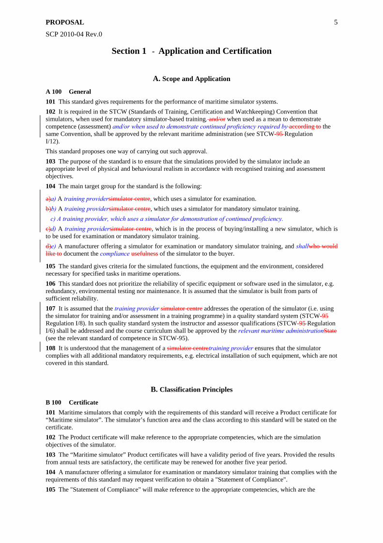
A 100 General 101 This standard gives requirements for the performance of maritime simulator systems. 102 It is required in the STCW (Standards of Training, Certification and Watchkeeping) Convention that simulators, when used for mandatory simulator-based training, and/or when used as a mean to demonstrate competence (assessment) and/or when used to demonstrate continued proficiency required by according to the same Convention, shall be approved by the relevant maritime administration (see STCW-95 Regulation I/12). This standard proposes one way of carrying out such approval. 103 The purpose of the standard is to ensure that the simulations provided by the simulator include an appropriate level of physical and behavioural realism in accordance with recognised training and assessment objectives. 104 The main target group for the standard is the following:
a)a) A training providersimulator centre, which uses a simulator for examination. b)b) A training providersimulator centre, which uses a simulator for mandatory simulator training. c) A training provider, which uses a simulator for demonstration of continued proficiency. c)d) A training providersimulator centre, which is in the process of buying/installing a new simulator, which is to be used for examination or mandatory simulator training. d)e) A manufacturer offering a simulator for examination or mandatory simulator training, and shallwho would like to document the compliance usefulness of the simulator to the buyer.
105 The standard gives criteria for the simulated functions, the equipment and the environment, considered necessary for specified tasks in maritime operations. 106 This standard does not prioritize the reliability of specific equipment or software used in the simulator, e.g. redundancy, environmental testing nor maintenance. It is assumed that the simulator is built from parts of sufficient reliability. 107 It is assumed that the training provider simulator centre addresses the operation of the simulator (i.e. using the simulator for training and/or assessment in a training programme) in a quality standard system (STCW-95 Regulation I/8). In such quality standard system the instructor and assessor qualifications (STCW-95 Regulation I/6) shall be addressed and the course curriculum shall be approved by the relevant maritime administrationState (see the relevant standard of competence in STCW-95). 108 It is understood that the management of a simulator centretraining provider ensures that the simulator complies with all additional mandatory requirements, e.g. electrical installation of such equipment, which are not covered in this standard.
B. Classification Principles
B 100 Certificate 101 Maritime simulators that comply with the requirements of this standard will receive a Product certificate for “Maritime simulator”. The simulator’s function area and the class according to this standard will be stated on the certificate. 102 The Product certificate will make reference to the appropriate competencies, which are the simulation objectives of the simulator. 103 The “Maritime simulator” Product certificates will have a validity period of five years. Provided the results from annual tests are satisfactory, the certificate may be renewed for another five year period. 104 A manufacturer offering a simulator for examination or mandatory simulator training that complies with the requirements of this standard may request verification to obtain a "Statement of Compliance". 105 The "Statement of Compliance" will make reference to the appropriate competencies, which are the
PROPOSAL
SCP 2010-04 Rev.0
6
simulation objectives of the simulator. 106 The "Statement of Compliance" will have a validity period of five years. Provided the results from renewal tests are satisfactory, the "Statement of Compliance" may be renewed for another five year period.
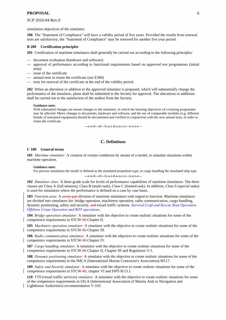
B 200 Certification principles 201 Certification of maritime simulators shall generally be carried out according to the following principles:
— document evaluation (hardware and software) — approval of performance according to functional requirements based on approved test programmes (initial
tests) — issue of the certificate — annual tests to retain the certificate (see E300) — tests for renewal of the certificate at the end of the validity period.
202 When an alteration or addition to the approved simulator is proposed, which will substantially change the performance of the simulator, plans shall be submitted to the Society for approval. The alterations or additions shall be carried out to the satisfaction of the auditor from the Society.
Guidance note: With substantial changes are meant changes to the simulator, in which the learning objectives of a training programme may be affected. Minor changes to documents, hardware and software, and the use of comparable modules (e.g. different brands of simulated equipment) should be documented and verified in conjunction with the next annual tests, in order to retain the certificate.
---e-n-d---of---G-u-i-d-a-n-c-e---n-o-t-e---
C. Definitions
C 100 General terms 101 Maritime simulator: A creation of certain conditions by means of a model, to simulate situations within maritime operation.
Guidance note: For process simulation the model is defined as the simulated propulsion type, in cargo handling the simulated ship type.
---e-n-d---of---G-u-i-d-a-n-c-e---n-o-t-e---
102 Simulator class: A three grade scale for levels of performance capabilities of maritime simulators. The three classes are Class A (full mission), Class B (multi-task), Class C (limited task). In addition, Class S (special tasks) is used for simulators where the performance is defined on a case by case basis. 103 Function area: A seven part division of maritime simulators with regard to function. Maritime simulators are divided into simulators for: bridge operation, machinery operation, radio communication, cargo handling, dynamic positioning, safety and security, and vessel traffic systems, Survival Craft and Rescue Boat Operation, Offshore Crane Operation and ROV operations. 104 Bridge operation simulator: A simulator with the objective to create realistic situations for some of the competence requirements in STCW-95 Chapter II. 105 Machinery operation simulator: A simulator with the objective to create realistic situations for some of the competence requirements in STCW-95 Chapter III. 106 Radio communication simulator: A simulator with the objective to create realistic situations for some of the competence requirements in STCW-95 Chapter IV. 107 Cargo handling simulator: A simulator with the objective to create realistic situations for some of the competence requirements in STCW-95 Chapter II, Chapter III and Regulation V/1. 108 Dynamic positioning simulator: A simulator with the objective to create realistic situations for some of the competence requirements in the IMCA (International Marine Contractor's Association) M117. 109 Safety and Security simulator: A simulator with the objective to create realistic situations for some of the competence requirements in STCW-95, chapter VI and ISPS B/13.1. 110 VTS (vessel traffic services) simulator: A simulator with the objective to create realistic situations for some of the competence requirements in IALA (International Association of Marine Aids to Navigation and Lighthouse Authorities) recommendation V-103.
PROPOSAL
SCP 2010-04 Rev.0
7
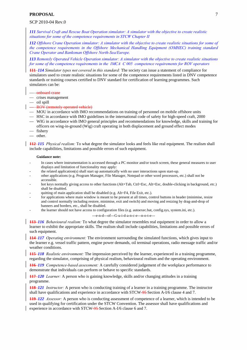
111 Survival Craft and Rescue Boat Operation simulator: A simulator with the objective to create realistic situations for some of the competence requirements in STCW Chapter II 112 Offshore Crane Operation simulator: A simulator with the objective to create realistic situations for some of the competence requirements in the Offshore Mechanical Handling Equipment (OMHEC) training standard Crane Operator and Banksman Offshore North-Sea/Europe. 113 Remotely Operated Vehicle Operation simulator: A simulator with the objective to create realistic situations for some of the competence requirements in the IMCA C 005 competence requirements for ROV operators 111 114 Simulator types not covered in this standard: The society can issue a statement of compliance for simulators used to create realistic situations for some of the competence requirements listed in DNV competence standards or training courses certified to DNV standard for certification of learning programmes. Such simulators can be:
— onboard crane — crises management — oil spill — ROV (remotely operated vehicle) — MOU in accordance with IMO recommendations on training of personnel on mobile offshore units — HSC in accordance with IMO guidelines in the international code of safety for high-speed craft, 2000 — WIG in accordance with IMO general principles and recommendations for knowledge, skills and training for
officers on wing-in-ground (Wig) craft operating in both displacement and ground effect modes — fishery — other.
112 115 Physical realism: To what degree the simulator looks and feels like real equipment. The realism shall include capabilities, limitations and possible errors of such equipment.
Guidance note: - In cases where instrumentation is accessed through a PC monitor and/or touch screen, these general measures to user
displays and limitation of functionality may apply: - the related application(s) shall start up automatically with no user interactions upon start-up. - other applications (e.g. Program Manager, File Manager, Notepad or other word processors, etc.) shall not be
accessible. - hot keys normally giving access to other functions (Alt+Tab, Ctrl+Esc, Alt+Esc, double-clicking in background, etc.)
shall be disabled. - quitting of main application shall be disabled (e.g. Alt+F4, File Exit, etc.). - for applications where main window is meant to be present at all times, control buttons in header (minimise, resize
and control normally including restore, minimise, exit and switch) and moving and resizing by drag-and-drop of banners and borders, etc., shall be disabled.
- the learner should not have access to configuration files (e.g. autoexec.bat, config.sys, system.ini, etc.). ---e-n-d---of---G-u-i-d-a-n-c-e---n-o-t-e---
113 116 Behavioural realism: To what degree the simulator resembles real equipment in order to allow a learner to exhibit the appropriate skills. The realism shall include capabilities, limitations and possible errors of such equipment. 114 117 Operating environment: The environment surrounding the simulated functions, which gives input to the learner e.g. vessel traffic pattern, engine power demands, oil terminal operations, radio message traffic and/or weather conditions. 115 118 Realistic environment: The impression perceived by the learner, experienced in a training programme, regarding the simulator, comprising of physical realism, behavioural realism and the operating environment. 116 119 Competence-based assessment: A carefully considered judgement of the workplace performance to demonstrate that individuals can perform or behave to specific standards. 117 120 Learner: A person who is gaining knowledge, skills and/or changing attitudes in a training programme. 118 121 Instructor: A person who is conducting training of a learner in a training programme. The instructor shall have qualifications and experience in accordance with STCW-95 Section A-I/6 clause 4 and 7. 119 122 Assessor: A person who is conducting assessment of competence of a learner, which is intended to be used in qualifying for certification under the STCW Convention. The assessor shall have qualifications and experience in accordance with STCW-95 Section A-I/6 clause 6 and 7.
PROPOSAL
SCP 2010-04 Rev.0
8
D. Documentation
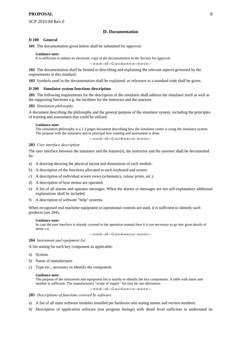
D 100 General 101 The documentation given below shall be submitted for approval.
Guidance note: It is sufficient to submit an electronic copy of the documentation to the Society for approval.
---e-n-d---of---G-u-i-d-a-n-c-e---n-o-t-e---
102 The documentation shall be limited to describing and explaining the relevant aspects governed by the requirements in this standard. 103 Symbols used in the documentation shall be explained, or reference to a standard code shall be given.
D 200 Simulator system functions description 201 The following requirements for the description of the simulator shall address the simulator itself as well as the supporting functions e.g. the facilities for the instructor and the assessor. 202 Simulation philosophy A document describing the philosophy and the general purpose of the simulator system, including the principles of training and assessment that could be utilised.
Guidance note: The simulation philosophy is a 1-2 pages document describing how the simulator centre is using the simulator system. The purpose with the simulator and in principal how training and assessment is done.
---e-n-d---of---G-u-i-d-a-n-c-e---n-o-t-e---
203 User interface description The user interface between the simulator and the learner(s), the instructor and the assessor shall be documented by:
a) A drawing showing the physical layout and dimensions of each module. b) A description of the functions allocated to each keyboard and screen. c) A description of individual screen views (schematics, colour prints, etc.). d) A description of how menus are operated. e) A list of all alarms and operator messages. When the alarms or messages are not self-explanatory additional
explanations shall be included. f) A description of software "help" systems.
When recognised real maritime equipment or operational controls are used, it is sufficient to identify such products (see 204).
Guidance note: In case the user interface is already covered in the operation manual then it is not necessary to go into great details of items c-e.
---e-n-d---of---G-u-i-d-a-n-c-e---n-o-t-e---
204 Instrument and equipment list A list stating for each key component as applicable:
a) System. b) Name of manufacturer. c) Type etc., necessary to identify the component.
Guidance note: The purpose of the instrument and equipment list is mainly to identify the key components. A table with name and number is sufficient. The manufacturers "scope of supply" list may be one alternative.
---e-n-d---of---G-u-i-d-a-n-c-e---n-o-t-e---
205 Descriptions of functions covered by software
a) A list of all main software modules installed per hardware unit stating names and version numbers. b) Description of application software (not program listings) with detail level sufficient to understand its

PROPOSAL
SCP 2010-04 Rev.0
9
function. c) Tools for system set-up and process equipment configuration.
206 Operation manual A document intended for regular use at the simulator centre, providing information as applicable to, but not limited to:
— operational mode of all modules, for normal system performance (baseline starting point) — operating instructions for normal operating mode.
D 300 Simulator performance description 301 It shall be documented that the simulator can be used for all of the defined simulation objectives.
Guidance note: The documentation may include one or more of the following: a) Cross reference between the STCW Convention competence requirements and simulation scenarios. b) Description of training exercises, including learning objectives, for each element of competence. c) Specification of the training type such as: emergency; optimization; procedures; maintenance; troubleshooting;
decision-making; teamwork; operator; part-tasking; component etc. d) Outline of how each element of competence can be assessed.
---e-n-d---of---G-u-i-d-a-n-c-e---n-o-t-e---
302 It shall be documented that the simulator can simulate the operating capabilities of real equipment concerned and includes the capabilities, limitations and possible errors of such equipment. 303 It shall be documented that the simulator is capable of producing a variety of conditions, which may include emergency, hazardous or unusual situations relevant to the simulation objectives. 304 When one ore more simulators are interconnected, the integration protocol used together with a description of which functions that are interfaced shall be documented.
D 400 Test programmes for functionality 401 Test programmes for the functionality of the simulator shall be submitted for approval. The main purpose is to verify the performance described in 300. The manufacturers "site acceptance test" (SAT) may be a point of origin. 402 The tests are only to cover requirements given by this standard. The test programmes shall specify in detail how the various functions shall be tested and what shall be observed during the tests. 403 Each test programme shall include a description of each test item and a description and justification of the acceptance criteria for each test.
Guidance note: In general the test program shall focus on operational tests in accordance with operational procedures of the simulation objective. i.e., from start-up to full operation like in a sea trial, all relevant operations in cargo handling, etc.
---e-n-d---of---G-u-i-d-a-n-c-e---n-o-t-e---
E. Tests
E 100 General 101 All tests shall be carried out according to test programmes approved by the Society. 102 The tests and visual examination shall verify that all relevant standard requirements are met. 103 The tests shall include the correct function of individual equipment packages, together with establishment of correct parameters for alarm, control and safety (time constants, set points, etc.). 104 Copies of the approved test programmes shall be kept with the simulator. It is to be completed with final set points and endorsed by the Society's auditor. 105 A change-log shall be kept updated with all changes and maintenance carried out on the simulator. The change-log shall at least include action, alteration achieved and date. A copy of the change-log shall be submitted to the Society in connection with renewal of the certificate.
E 200 Initial tests to attain the certificate 201 The tests shall be conducted when the simulator is fully assembled to a complete and final unit. The tests
PROPOSAL
SCP 2010-04 Rev.0
10
shall be witnessed by an auditor from the Society.
E 300 Annual tests to retain the certificate 301 The annual tests shall be conducted when the simulator is under normal operation. The tests shall be witnessed by an auditor from the Society. 302 Under the condition that the simulator centretraining provider has a certified quality standard system, either an ISO 9000 certificate awarded by any accredited body or a certificate according to the DNV Standard for Certification of Maritime Simulator Centres, then the annual tests may be carried out solely by the simulator centre. 303 The test results and a copy of the change-log shall be submitted to the Society for approval and recording.
E 400 Tests for renewal of the certificate 401 The tests shall be conducted when the simulator is under normal operation. The tests shall be witnessed by an auditor from the Society.
PROPOSAL
SCP 2010-04 Rev.0
11
Section 2 - General
A. Simulator Equipment
A 100 General 101 Each piece of equipment installed in the simulator shall have a similar functionality to corresponding real equipment used. 102 If any piece of equipment does not correspond to a specific make, the applicable IMO (International Maritime Organization) performance standard (functionality requirements only) for such equipment shall be followed. If such a performance standard does not exist, then the functionality of the equipment shall, as a minimum, be the same as for any recognised genuine equipment of that type, in use. 103 Each piece of equipment shall resemble the behavioural characteristics, e.g. accuracy, reaction time and other limitations, related to corresponding equipment in use. 104 User manuals for the simulator equipment and operational controls shall be available to the learners for use during exercises.
Guidance note: If emulated instrumentation is used the following requirements apply: a) Digital and analogue instrumentation shall be grouped and positioned into realistic function areas. b) The visual proportion of the emulated instruments shall be close to real instrumentation. c) Scale and range shall be in accordance with real instrumentation. d) It shall be possible to dim indication lamps and digital readings where applicable. e) When computer generated sound indicators, buzzers and sirens are used, it shall have adequate loudness and similar
tone and repetition frequency as for real instrumentation. ---e-n-d---of---G-u-i-d-a-n-c-e---n-o-t-e---
B. Instructor and Assessor facilities
B 100 General 101 The simulator shall include instructor and assessor facilities where exercises may be controlled. 102 The instructor and the assessor shall be able to:
a) Start, halt, reset in time and place, and restart an exercise. b) Change the operating environment during an exercise. c) Communicate with the learners (i.e. simulate the outside world) on relevant communication channels. d) Follow the conversations of the learners (Class A to B only). e) Visually follow the proceedings of an exercise by any method. f) Plot conducted exercises (e.g. ship tracks, targets, and coastline) by any method (bridge operation only). g) Activate simulation of relevant failures in all equipment used.
103 The instructor and the assessor shall have access to an operation manual or equivalent with contents as outlined in Sec.1 D206. 104 It shall be possible to replay a full exercise showing the actions performed by the learners. The replay shall be possible in time other than real time (i.e. slow motion and rapid speed). The purpose is to trace and replay sequences of special interest in the exercise. 105 The instructor and assessor facilities shall include possibilities to set up a scoring or grading method to assess performance of the learner.
Guidance note: A scoring and grading possibility may include: a) Monitoring of selected parameters, continuous or at selected stages. b) Comparing these with norm values, weighing and counting the deviation. c) Presenting these values and deviations in an understandable manner upon completion of the exercise.
---e-n-d---of---G-u-i-d-a-n-c-e---n-o-t-e---
106 The instructor and assessor facilities should include possibilities to set the exercise to any position in the

PROPOSAL
SCP 2010-04 Rev.0
12
replay and let the learner start over from the set time.
Guidance note: When real equipment is interfaced, it might not be possible to playback all data in the same application. It will in those cases be acceptable to have a video logger that is able to save screens and data from other systems provided that this can be synchronised and displayed in the playback.
---e-n-d---of---G-u-i-d-a-n-c-e---n-o-t-e---
PROPOSAL
SCP 2010-04 Rev.0
13
Section 3 - Bridge Operation
A. Simulator Class - Bridge Operation
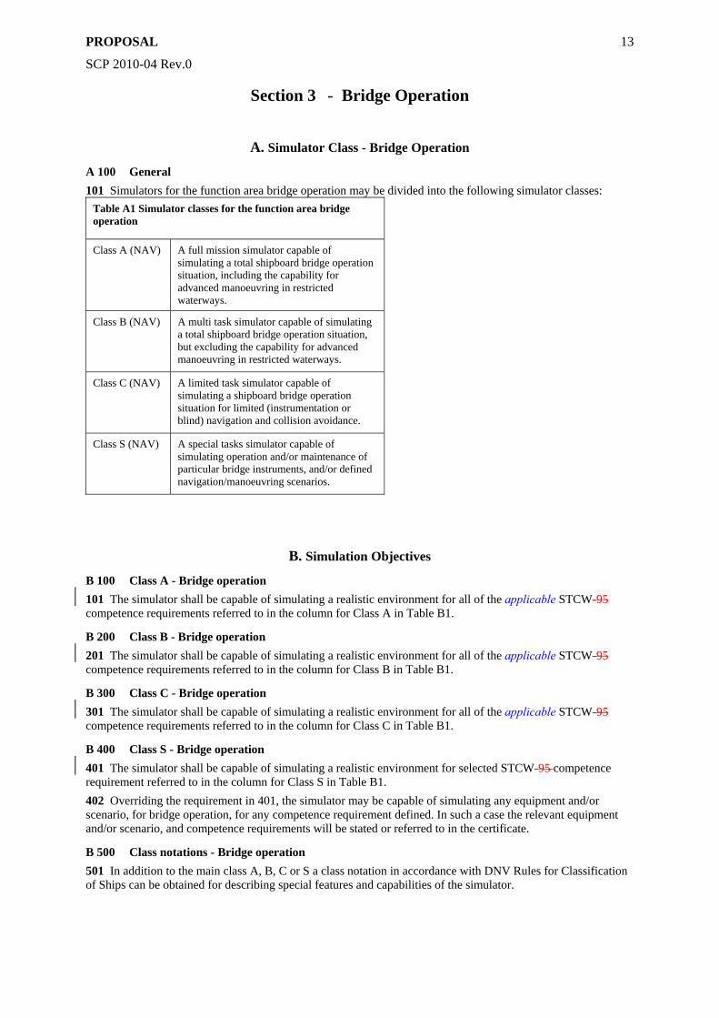
A 100 General 101 Simulators for the function area bridge operation may be divided into the following simulator classes:
Table A1 Simulator classes for the function area bridge operation
Class A (NAV) A full mission simulator capable of simulating a total shipboard bridge operation situation, including the capability for advanced manoeuvring in restricted waterways.
Class B (NAV) A multi task simulator capable of simulating a total shipboard bridge operation situation, but excluding the capability for advanced manoeuvring in restricted waterways.
Class C (NAV) A limited task simulator capable of simulating a shipboard bridge operation situation for limited (instrumentation or blind) navigation and collision avoidance.
Class S (NAV) A special tasks simulator capable of simulating operation and/or maintenance of particular bridge instruments, and/or defined navigation/manoeuvring scenarios.
B. Simulation Objectives
B 100 Class A - Bridge operation 101 The simulator shall be capable of simulating a realistic environment for all of the applicable STCW-95 competence requirements referred to in the column for Class A in Table B1.
B 200 Class B - Bridge operation 201 The simulator shall be capable of simulating a realistic environment for all of the applicable STCW-95 competence requirements referred to in the column for Class B in Table B1.
B 300 Class C - Bridge operation 301 The simulator shall be capable of simulating a realistic environment for all of the applicable STCW-95 competence requirements referred to in the column for Class C in Table B1.
B 400 Class S - Bridge operation 401 The simulator shall be capable of simulating a realistic environment for selected STCW-95 competence requirement referred to in the column for Class S in Table B1. 402 Overriding the requirement in 401, the simulator may be capable of simulating any equipment and/or scenario, for bridge operation, for any competence requirement defined. In such a case the relevant equipment and/or scenario, and competence requirements will be stated or referred to in the certificate.
B 500 Class notations - Bridge operation 501 In addition to the main class A, B, C or S a class notation in accordance with DNV Rules for Classification of Ships can be obtained for describing special features and capabilities of the simulator.
PROPOSAL
SCP 2010-04 Rev.0
14
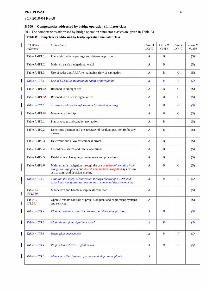
B 600 Competencies addressed by bridge operation simulator class 601 The competencies addressed by bridge operation simulator classes are given in Table B1.
Table B1 Competencies addressed by bridge operation simulator class
STCW-95 reference
Competence Class A (NAV)
Class B (NAV)
Class C (NAV)
Class S (NAV)
Table A-II/1.1 Plan and conduct a passage and determine position A B (S)
Table A-II/1.2 Maintain a safe navigational watch A B (S)
Table A-II/1.3 Use of radar and ARPA to maintain safety of navigation A B C (S)
Table A-II/1.4 Use of ECDIS to maintain the safety of navigation A B C (S)
Table A-II/1.45 Respond to emergencies A B C (S)
Table A-II/1.56 Respond to a distress signal at sea A B C (S)
Table A-II/1.8 Transmit and receive information by visual signalling A B C (S)
Table A-II/1.89 Manoeuvre the ship A B C (S)
Table A-II/2.1 Plan a voyage and conduct navigation A B (S)
Table A-II/2.2 Determine position and the accuracy of resultant position fix by any means
A B (S)
Table A-II/2.3 Determine and allow for compass errors A B (S)
Table A-II/2.4 Co-ordinate search and rescue operations A B (S)
Table A-II/2.5 Establish watchkeeping arrangements and procedures A B (S)
Table A-II/2.6 Maintain safe navigation through the use of radar information from navigation equipment and ARPA and modern navigation systems to assist command decision-making
A B C (S)
Table A-II/2.7 Maintain the safety of navigation through the use of ECDIS and associated navigation systems to assist command decision making
A B C (S)
Table A-III/2.910
Manoeuvre and handle a ship in all conditions A (S)
Table A-II/2.101
Operate remote controls of propulsion plant and engineering systems and services
A (S)
Table A-II/3.1 Plan and conduct a coastal passage and determine position A B (S)
Table A-II/3.2 Maintain a safe navigational watch A B (S)
Table A-II/3.3 Respond to emergencies A B C (S)
Table A-II/3.4 Respond to a distress signal at sea A B C (S)
Table A-II/3.5 Manoeuvre the ship and operate small ship power plants A
PROPOSAL
SCP 2010-04 Rev.0
15
Table A-II/5.2 Contribute to berthing, anchoring and other mooring operations A B C (S)
C. Simulator requirements
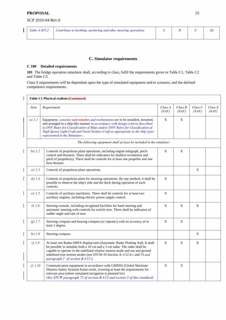
C 100 Detailed requirements 101 The bridge operation simulator shall, according to class, fulfil the requirements given in Table C1, Table C2 and Table C3. Class S requirements will be dependant upon the type of simulated equipment and/or scenario, and the defined competence requirements.
Table C1 Physical realism (Continued)
Item Requirement Class A (NAV)
Class B (NAV)
Class C (NAV)
Class S (NAV)
a1.1.1 Equipment, consoles and consoles and workstations are to be installed, mounted, and arranged in a ship-like manner in accordance with design criteria described in DNV Rules for Classification of Ships and/or DNV Rules for Classification of High Speed, Light Craft and Naval Surface Craft as appropriate to the ship types represented in the Simulator..
X X
The following equipment shall at least be included in the simulator:
b1.1.2 Controls of propulsion plant operations, including engine telegraph, pitch-control and thrusters. There shall be indicators for shaft(s) revolutions and pitch of propeller(s). There shall be controls for at least one propeller and one bow thruster.
X X
c1.1.3 Controls of propulsion plant operations. X
d1.1.4 Controls of propulsion plant for mooring operations. By any method, it shall be possible to observe the ship's side and the dock during operation of such controls.
X
e1.1.5 Controls of auxiliary machinery. There shall be controls for at least two auxiliary engines, including electric power supply control.
X
f1.1.6 Steering console, including recognised facilities for hand steering and automatic steering with controls for switch over. There shall be indicators of rudder angle and rate of turn.
X X X
g1.1.7 Steering compass and bearing compass (or repeater) with an accuracy of at least 1 degree.
X X
h1.1.8 Steering compass. X
i1.1.9 At least one Radar/ARPA display/unit (Automatic Radar Plotting Aid). It shall be possible to simulate both a 10 cm and a 3 cm radar. The radar shall be capable to operate in the stabilised relative motion mode and sea and ground stabilised true motion modes (see STCW-95 Section A-1/12.4.1 and 53 and paragraph 2 of section B-I/12 ).
X X X
j1.1.10 Communication equipment in accordance with GMDSS (Global Maritime Distress Safety System) frame-work, covering at least the requirements for relevant area (where simulated navigation is planned for). (See STCW paragraph 72 of section B-I/12 and section 5 of this standard)
X X
PROPOSAL
SCP 2010-04 Rev.0
16
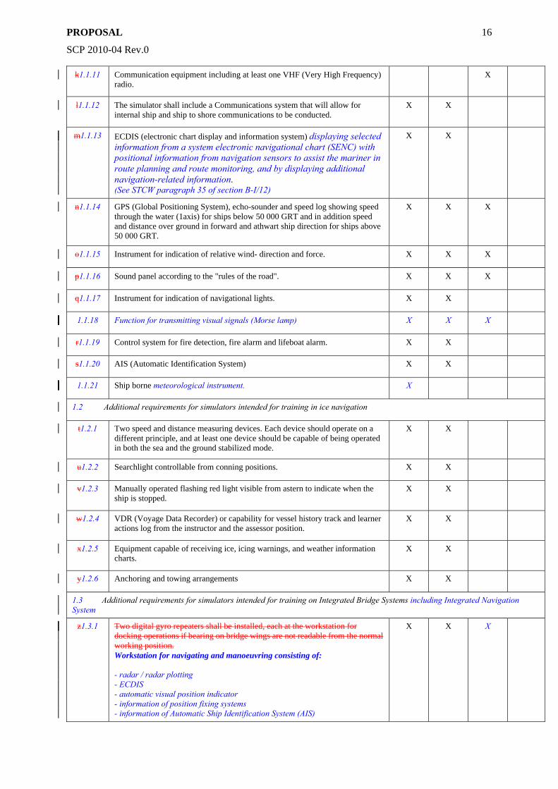
k1.1.11 Communication equipment including at least one VHF (Very High Frequency) radio.
X
l1.1.12 The simulator shall include a Communications system that will allow for internal ship and ship to shore communications to be conducted.
X X
m1.1.13 ECDIS (electronic chart display and information system) displaying selected information from a system electronic navigational chart (SENC) with positional information from navigation sensors to assist the mariner in route planning and route monitoring, and by displaying additional navigation-related information. (See STCW paragraph 35 of section B-I/12)
X X
n1.1.14 GPS (Global Positioning System), echo-sounder and speed log showing speed through the water (1axis) for ships below 50 000 GRT and in addition speed and distance over ground in forward and athwart ship direction for ships above 50 000 GRT.
X X X
o1.1.15 Instrument for indication of relative wind- direction and force. X X X
p1.1.16 Sound panel according to the "rules of the road". X X X
q1.1.17 Instrument for indication of navigational lights. X X
1.1.18 Function for transmitting visual signals (Morse lamp) X X X
r1.1.19 Control system for fire detection, fire alarm and lifeboat alarm. X X
s1.1.20 AIS (Automatic Identification System) X X
1.1.21 Ship borne meteorological instrument. X
1.2 Additional requirements for simulators intended for training in ice navigation
t1.2.1 Two speed and distance measuring devices. Each device should operate on a different principle, and at least one device should be capable of being operated in both the sea and the ground stabilized mode.
X X
u1.2.2 Searchlight controllable from conning positions. X X
v1.2.3 Manually operated flashing red light visible from astern to indicate when the ship is stopped.
X X
w1.2.4 VDR (Voyage Data Recorder) or capability for vessel history track and learner actions log from the instructor and the assessor position.
X X
x1.2.5 Equipment capable of receiving ice, icing warnings, and weather information charts.
X X
y1.2.6 Anchoring and towing arrangements X X
1.3 Additional requirements for simulators intended for training on Integrated Bridge Systems including Integrated Navigation System
z1.3.1 Two digital gyro repeaters shall be installed, each at the workstation for docking operations if bearing on bridge wings are not readable from the normal working position. Workstation for navigating and manoeuvring consisting of: - radar / radar plotting - ECDIS - automatic visual position indicator - information of position fixing systems - information of Automatic Ship Identification System (AIS)
X X X
PROPOSAL
SCP 2010-04 Rev.0
17
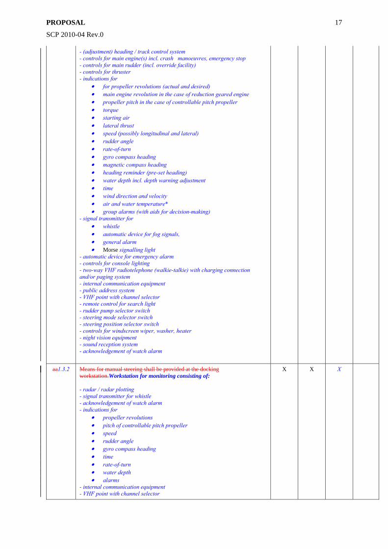
- (adjustment) heading / track control system - controls for main engine(s) incl. crash manoeuvres, emergency stop - controls for main rudder (incl. override facility) - controls for thruster - indications for
• for propeller revolutions (actual and desired) • main engine revolution in the case of reduction geared engine • propeller pitch in the case of controllable pitch propeller • torque • starting air • lateral thrust • speed (possibly longitudinal and lateral) • rudder angle • rate-of-turn • gyro compass heading • magnetic compass heading • heading reminder (pre-set heading) • water depth incl. depth warning adjustment • time • wind direction and velocity • air and water temperature* • group alarms (with aids for decision-making)
- signal transmitter for • whistle • automatic device for fog signals, • general alarm • Morse signalling light
- automatic device for emergency alarm - controls for console lighting - two-way VHF radiotelephone (walkie-talkie) with charging connection and/or paging system - internal communication equipment - public address system - VHF point with channel selector - remote control for search light - rudder pump selector switch - steering mode selector switch - steering position selector switch - controls for windscreen wiper, washer, heater - night vision equipment - sound reception system - acknowledgement of watch alarm
aa1.3.2 Means for manual steering shall be provided at the docking workstation.Workstation for monitoring consisting of: - radar / radar plotting - signal transmitter for whistle - acknowledgement of watch alarm - indications for
• propeller revolutions • pitch of controllable pitch propeller • speed • rudder angle • gyro compass heading • time • rate-of-turn • water depth • alarms
- internal communication equipment - VHF point with channel selector
X X X
PROPOSAL
SCP 2010-04 Rev.0
18
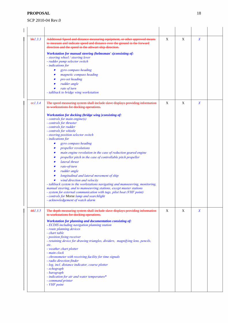
bb1.3.3 Additional Speed and distance measuring equipment, or other approved means to measure and indicate speed and distance over the ground in the forward direction and the speed in the athwart ship direction.
Workstation for manual steering (helmsman' s)consisting of: - steering wheel / steering lever - rudder pump selector switch - indications for
• gyro compass heading • magnetic compass heading • pre-set heading • rudder angle • rate of turn
- talkback to bridge wing workstation
X X X
cc1.3.4 The speed measuring system shall include slave displays providing information to workstations for docking operations. Workstation for docking (bridge wing )consisting of: - controls for main engine(s) - controls for thruster - controls for rudder - controls for whistle - steering position selector switch - indications for
• gyro compass heading • propeller revolutions • main engine revolution in the case of reduction geared engine • propeller pitch in the case of controllable pitch propeller • lateral thrust • rate-of-turn • rudder angle • longitudinal and lateral movement of ship • wind direction and velocity
- talkback system to the workstations navigating and manoeuvring, monitoring, manual steering, and to manoeuvring stations, except muster stations - system for external communication with tugs, pilot boat (VHF point) - controls for Morse lamp and searchlight - acknowledgement of watch alarm
X X X
dd1.3.5 The depth measuring system shall include slave displays providing information to workstations for docking operations.
Workstation for planning and documentation consisting of: - ECDIS including navigation planning station - route planning devices - chart table - position fixing receiver - retaining device for drawing triangles, dividers, magnifying lens, pencils, etc. - weather chart plotter - main clock - chronometer with receiving facility for time signals - radio direction finder - log, incl. distance indicator, course plotter - echograph - barograph - indication for air and water temperature* - command printer - VHF point
X X X
PROPOSAL
SCP 2010-04 Rev.0
19
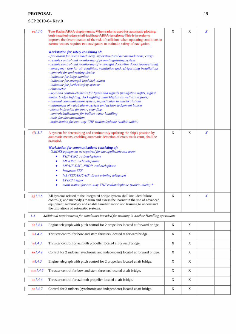
ee1.3.6 Two Radar/ARPA display/units. When radar is used for automatic plotting, both installed radars shall facilitate ARPA functions. This is in order to improve the determination of the risk of collision, when operating conditions in narrow waters requires two navigators to maintain safety of navigation. Workstation for safety consisting of: - fire alarm for areas machinery, superstructure/ accommodations, cargo - remote control and monitoring of fire-extinguishing system - remote control and monitoring of watertight doors/fire doors (open/closed) - emergency stop for air condition, ventilation and refrigerating installations - controls for anti-rolling device - indicator for bilge monitor - indicator for strength load incl. alarm - indicator for further safety systems - clinometer - keys and control-elements for lights and signals (navigation lights, signal lamps, bridge lighting, deck lighting searchlights, as well as all fuses) - internal communication system, in particular to muster stations - adjustment of watch alarm system and acknowledgement button - status indication for bow-, rear-flap - controls/indications for ballast water handling - tools for documentation - main station for two-way VHF radiotelephone (walkie-talkie)
X X X
ff1.3.7 A system for determining and continuously updating the ship's position by automatic means, enabling automatic detection of cross-track-error, shall be provided.
Workstation for communications consisting of: - GMDSS equipment as required for the applicable sea area:
• VHF-DSC, radiotelephone • MF-DSC, radiotelephone • MF/HF-DSC, NBDP, radiotelephone • Inmarsat-SES • NAVTEX/EGC/HF direct printing telegraph • EPIRB trigger • main station for two-way VHF radiotelephone (walkie-talkie) *
X X X
gg1.3.8 All systems related to the integrated bridge system shall included failure control(s) and method(s) to train and assess the learner in the use of advanced equipment, technology and enable familiarization and training to understand the limitations of automatic systems.
X X X
1.4 Additional requirements for simulators intended for training in Anchor Handling operations
hh1.4.1 Engine telegraph with pitch control for 2 propellers located at forward bridge. X X
ii1.4.2 Thruster control for bow and stern thrusters located at forward bridge. X X
jj1.4.3 Thruster control for azimuth propeller located at forward bridge. X X
kk1.4.4 Control for 2 rudders (synchronic and independent) located at forward bridge. X X
ll1.4.5 Engine telegraph with pitch control for 2 propellers located at aft bridge. X X
mm1.4.5 Thruster control for bow and stern thrusters located at aft bridge. X X
nn1.4.6 Thruster control for azimuth propeller located at aft bridge. X X
oo1.4.7 Control for 2 rudders (synchronic and independent) located at aft bridge. X X
PROPOSAL
SCP 2010-04 Rev.0
20
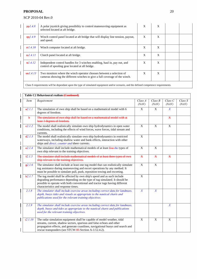
pp1.4.8 A polar joystick giving possibility to control manoeuvring equipment as selected located at aft bridge.
X X
qq1.4.9 Winch control panel located at aft bridge that will display line tension, payout, and speed.
X X
rr1.4.10 Winch computer located at aft bridge. X X
ss1.4.11 Clutch panel located at aft bridge. X X
tt1.4.12 Independent control handles for 3 winches enabling, haul in, pay out, and control of spooling gear located at aft bridge.
X X
uu1.4.13 Two monitors where the winch operator chooses between a selection of cameras showing the different winches to give a full coverage of the winch.
X X
Class S requirements will be dependant upon the type of simulated equipment and/or scenario, and the defined competence requirements.
Table C2 Behavioural realism (Continued)
Item Requirement Class A (NAV)
Class B (NAV)
Class C (NAV)
Class S (NAV)
a2.1.1 The simulation of own ship shall be based on a mathematical model with 6 degrees of freedom.
X X X
b The simulation of own ship shall be based on a mathematical model with at least 3 degrees of freedom.
X
c2.1.2 The model shall realistically simulate own ship hydrodynamics in open water conditions, including the effects of wind forces, wave forces, tidal stream and currents.
X X X
d2.1.3 The model shall realistically simulate own ship hydrodynamics in restricted waterways, including shallow water and bank effects, interaction with other ships and direct, counter and sheer currents.
X
e2.1.4 The simulator shall include mathematical models of at least five the types of own ship relevant to the training objectives.
X X
f2.1.5 The simulator shall include mathematical models of at least three types of own ship relevant to the training objectives.
X X X
g2.1.6 The simulator shall include at least one tug model that can realistically simulate tug assistance during manoeuvring and escort operations by any method. It must be possible to simulate pull, push, reposition towing and escorting.
X X
h2.1.7 The tug model shall be affected by own ship's speed and as such include degrading performance depending on the type of tug simulated. It should be possible to operate with both conventional and tractor tugs having different characteristics and response times.
X
2.1.8 The simulator shall include exercise areas including correct data for landmass, depth, buoys tides and visuals as appropriate to the nautical charts and publications used for the relevant training objectives.
X X
2.1.9 The simulator shall include exercise areas including correct data for landmass, depth, buoys and tides as appropriate to the nautical charts and publications used for the relevant training objectives.
X
i2.1.10 The radar simulation equipment shall be capable of model weather, tidal streams, current, shadow sectors, spurious and false echoes and other propagation effects, and generate coastlines, navigational buoys and search and rescue transponders (see STCW-95 Section A-1/12.4.2).
X X X
PROPOSAL
SCP 2010-04 Rev.0
21
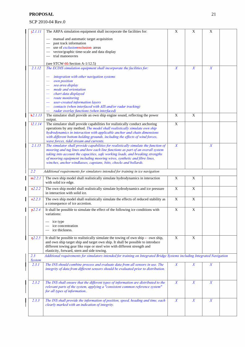
j2.1.11 The ARPA simulation equipment shall incorporate the facilities for:
— manual and automatic target acquisition — past track information — use of exclusionexclusion areas — vector/graphic time-scale and data display — trial manoeuvres
(see STCW-95 Section A-1/12.5)
X X X
2.1.12 The ECDIS simulation equipment shall incorporate the facilities for: — integration with other navigation systems — own position — sea area display — mode and orientation — chart data displayed — route monitoring — user-created information layers — contacts (when interfaced with AIS and/or radar tracking) — radar overlay functions (when interfaced)
X X X
k2.1.13 The simulator shall provide an own ship engine sound, reflecting the power output.
X X
l2.1.14 The simulator shall provide capabilities for realistically conduct anchoring operations by any method. The model shall realistically simulate own ship hydrodynamics in interaction with applicable anchor and chain dimensions with different bottom holding grounds, including the effects of wind forces, wave forces, tidal stream and currents.
X
2.1.15 The simulator shall provide capabilities for realistically simulate the function of mooring and tug lines and how each line functions as part of an overall system taking into account the capacities, safe working loads, and breaking strengths of mooring equipment including mooring wires, synthetic and fibre lines, winches, anchor windlasses, capstans, bitts, chocks and bollards.
X X
2.2 Additional requirements for simulators intended for training in ice navigation
m2.2.1 The own ship model shall realistically simulate hydrodynamics in interaction with solid ice edge.
X X
n2.2.2 The own ship model shall realistically simulate hydrodynamics and ice pressure in interaction with solid ice.
X X
o2.2.3 The own ship model shall realistically simulate the effects of reduced stability as a consequence of ice accretion.
X X
p2.2.4 It shall be possible to simulate the effect of the following ice conditions with variations:
— ice type — ice concentration — ice thickness.
X X
q2.2.5 It shall be possible to realistically simulate the towing of own ship -– own ship, and own ship target ship and target own ship. It shall be possible to introduce different towing gear like rope or steel wire with different strength and elasticity, forward, stern and side towing.
X X
2.3 Additional requirements for simulators intended for training on Integrated Bridge Systems including Integrated Navigation System 2.3.1 The INS should combine process and evaluate data from all sensors in use. The
integrity of data from different sensors should be evaluated prior to distribution. X X X
2.3.2 The INS shall ensure that the different types of information are distributed to the relevant parts of the system, applying a "consistent common reference system" for all types of information..
X X X
2.3.3 The INS shall provide the information of position, speed, heading and time, each clearly marked with an indication of integrity.
X X X
PROPOSAL
SCP 2010-04 Rev.0
22
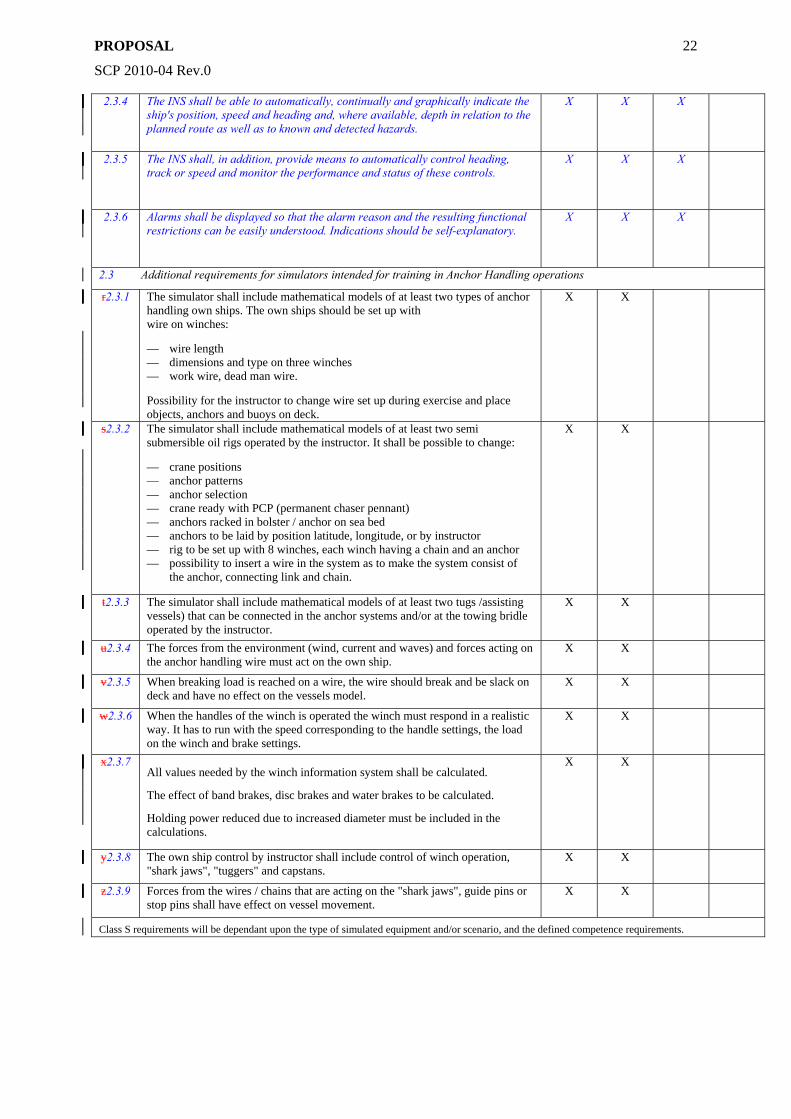
2.3.4 The INS shall be able to automatically, continually and graphically indicate the ship's position, speed and heading and, where available, depth in relation to the planned route as well as to known and detected hazards.
X X X
2.3.5 The INS shall, in addition, provide means to automatically control heading, track or speed and monitor the performance and status of these controls.
X X X
2.3.6 Alarms shall be displayed so that the alarm reason and the resulting functional restrictions can be easily understood. Indications should be self-explanatory.
X X X
2.3 Additional requirements for simulators intended for training in Anchor Handling operations
r2.3.1 The simulator shall include mathematical models of at least two types of anchor handling own ships. The own ships should be set up with wire on winches:
— wire length — dimensions and type on three winches — work wire, dead man wire.
Possibility for the instructor to change wire set up during exercise and place objects, anchors and buoys on deck.
X X
s2.3.2 The simulator shall include mathematical models of at least two semi submersible oil rigs operated by the instructor. It shall be possible to change:
— crane positions — anchor patterns — anchor selection — crane ready with PCP (permanent chaser pennant) — anchors racked in bolster / anchor on sea bed — anchors to be laid by position latitude, longitude, or by instructor — rig to be set up with 8 winches, each winch having a chain and an anchor — possibility to insert a wire in the system as to make the system consist of
the anchor, connecting link and chain.
X X
t2.3.3 The simulator shall include mathematical models of at least two tugs /assisting vessels) that can be connected in the anchor systems and/or at the towing bridle operated by the instructor.
X X
u2.3.4 The forces from the environment (wind, current and waves) and forces acting on the anchor handling wire must act on the own ship.
X X
v2.3.5 When breaking load is reached on a wire, the wire should break and be slack on deck and have no effect on the vessels model.
X X
w2.3.6 When the handles of the winch is operated the winch must respond in a realistic way. It has to run with the speed corresponding to the handle settings, the load on the winch and brake settings.
X X
x2.3.7 All values needed by the winch information system shall be calculated. The effect of band brakes, disc brakes and water brakes to be calculated. Holding power reduced due to increased diameter must be included in the calculations.
X X
y2.3.8 The own ship control by instructor shall include control of winch operation, "shark jaws", "tuggers" and capstans.
X X
z2.3.9 Forces from the wires / chains that are acting on the "shark jaws", guide pins or stop pins shall have effect on vessel movement.
X X
Class S requirements will be dependant upon the type of simulated equipment and/or scenario, and the defined competence requirements.
PROPOSAL
SCP 2010-04 Rev.0
23
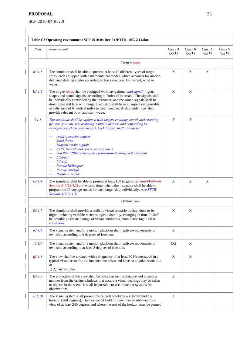
Table C3 Operating environment SCP 2010-04 Rev.0 (HOTI) - SfC 2.14.doc
Item Requirement Class A (NAV)
Class B (NAV)
Class C (NAV)
Class S (NAV)
Targets ships
a3.1.1 The simulator shall be able to present at least 10 different types of target ships, each equipped with a mathematical model, which accounts for motion, drift and steering angles according to forces induced by current, wind or wave.
X X X
b3.1.2 The targets ships shall be equipped with navigational and signal - lights, shapes and sound signals, according to "rules of the road". The signals shall be individually controlled by the instructor, and the sound signals shall be directional and fade with range. Each ship shall have an aspect recognisable at a distance of 6 nautical miles in clear weather. A ship under way shall provide relevant bow- and stern wave.
X X
3.1.3 The simulator shall be equipped with targets enabling search and rescuing persons from the sea, assisting a ship in distress and responding to emergencies which arise in port. Such targets shall at least be: — rocket parachute flares — hand flares — buoyant smoke signals — SART (search and rescue transponder). — Satellite EPIRB (emergency position-indicating radio beacon). — Lifeboat — Liferaft — Rescue Helicopter — Rescue Aircraft — People in water
X X
c3.1.4 The simulator shall be able to present at least 100 target ships (see STCW-95 Section A-1/12.4.3) at the same time, where the instructor shall be able to programme 20 voyage routes for each target ship individually. (see STCW Section A-1/12.4.3)
X X X
Outside view
d3.1.5 The simulator shall provide a realistic visual scenario by day, dusk or by night, including variable meteorological visibility, changing in time. It shall be possible to create a range of visual conditions, from dense fog to clear conditions.
X X
e3.1.6 The visual system and/or a motion platform shall replicate movements of own ship according to 6 degrees of freedom.
X
f3.1.7 The visual system and/or a motion platform shall replicate movements of own ship according to at least 3 degrees of freedom.
(X) X
g3.1.8 The view shall be updated with a frequency of at least 30 Hz measured in a typical visual scene for the intended exercises and have an angular resolution of ≤ 2,5 arc minutes.
X X
h3.1.9 The projection of the view shall be placed at such a distance and in such a manner from the bridge windows that accurate visual bearings may be taken to objects in the scene. It shall be possible to use binocular systems for observations.
X
i3.1.10 The visual system shall present the outside world by a view around the horizon (360 degrees). The horizontal field of view may be obtained by a view of at least 240 degrees and where the rest of the horizon may be panned
X
PROPOSAL
SCP 2010-04 Rev.0
24
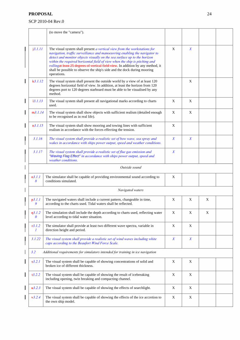
(to move the "camera").
j3.1.11 The visual system shall present a vertical view from the workstations for navigation, traffic surveillance and manoeuvring enabling the navigator to detect and monitor objects visually on the sea surface up to the horizon within the required horizontal field of view when the ship is pitching and rollingat least 25 degrees of vertical field view. In addition by any method, it shall be possible to observe the ship's side and the dock during mooring operations.
X X
k3.1.12 The visual system shall present the outside world by a view of at least 120 degrees horizontal field of view. In addition, at least the horizon from 120 degrees port to 120 degrees starboard must be able to be visualised by any method.
X
l3.1.13 The visual system shall present all navigational marks according to charts used.
X X
m3.1.14 The visual system shall show objects with sufficient realism (detailed enough to be recognised as in real life).
X X
n3.1.15 The visual system shall show mooring and towing lines with sufficient realism in accordance with the forces effecting the tension.
X
3.1.16 The visual system shall provide a realistic set of bow wave, sea spray and wakes in accordance with ships power output, speed and weather conditions.
X X
3.1.17 The visual system shall provide a realistic set of flue gas emission and "Waving Flag Effect" in accordance with ships power output, speed and weather conditions.
X
Outside sound
o3.1.18
The simulator shall be capable of providing environmental sound according to conditions simulated.
X
Navigated waters
p3.1.19
The navigated waters shall include a current pattern, changeable in time, according to the charts used. Tidal waters shall be reflected.
X X X
q3.1.20
The simulation shall include the depth according to charts used, reflecting water level according to tidal water situation.
X X X
r3.1.21
The simulator shall provide at least two different wave spectra, variable in direction height and period.
X X
3.1.22 The visual system shall provide a realistic set of wind waves including white caps according to the Beaufort Wind Force Scale.
X X
3.2 Additional requirements for simulators intended for training in ice navigation
s3.2.1 The visual system shall be capable of showing concentrations of solid and broken ice of different thickness.
X X
t3.2.2 The visual system shall be capable of showing the result of icebreaking including opening, twin breaking and compacting channel.
X X
u3.2.3 The visual system shall be capable of showing the effects of searchlight. X X
v3.2.4 The visual system shall be capable of showing the effects of the ice accretion to the own ship model.
X X
PROPOSAL
SCP 2010-04 Rev.0
25
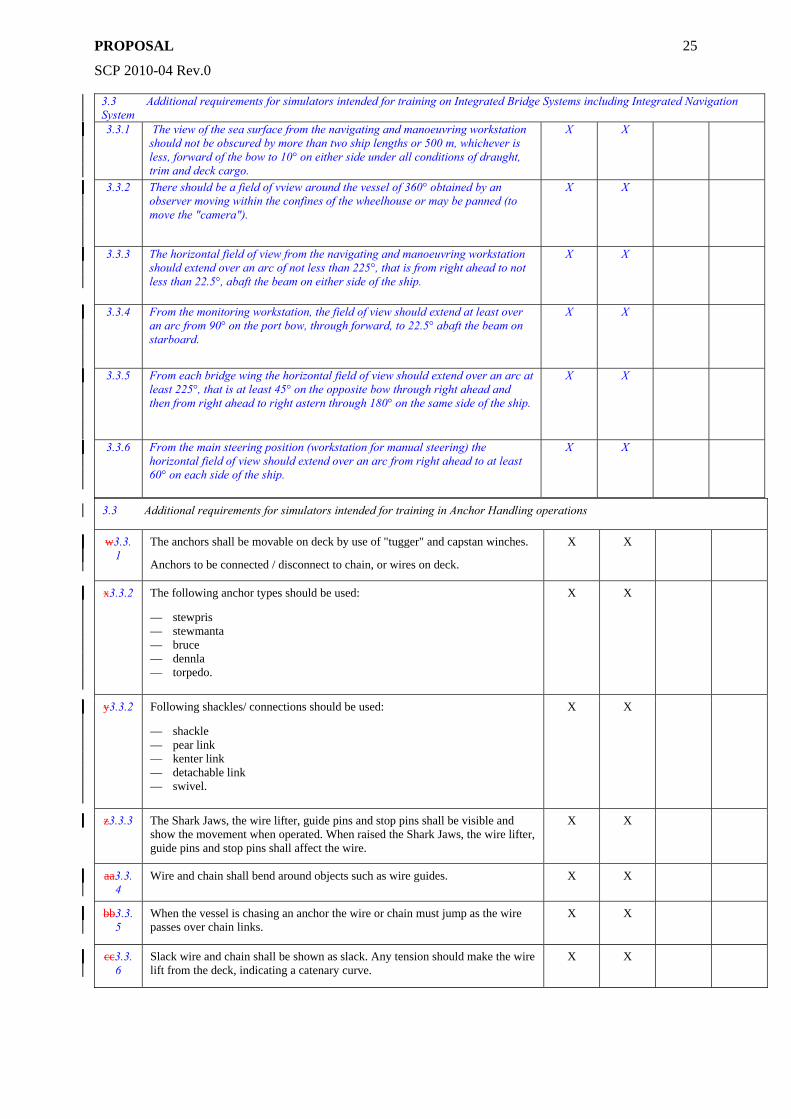
3.3 Additional requirements for simulators intended for training on Integrated Bridge Systems including Integrated Navigation System 3.3.1 The view of the sea surface from the navigating and manoeuvring workstation
should not be obscured by more than two ship lengths or 500 m, whichever is less, forward of the bow to 10° on either side under all conditions of draught, trim and deck cargo.
X X
3.3.2 There should be a field of vview around the vessel of 360° obtained by an observer moving within the confines of the wheelhouse or may be panned (to move the "camera").
X X
3.3.3 The horizontal field of view from the navigating and manoeuvring workstation should extend over an arc of not less than 225°, that is from right ahead to not less than 22.5°, abaft the beam on either side of the ship.
X X
3.3.4 From the monitoring workstation, the field of view should extend at least over an arc from 90° on the port bow, through forward, to 22.5° abaft the beam on starboard.
X X
3.3.5 From each bridge wing the horizontal field of view should extend over an arc at least 225°, that is at least 45° on the opposite bow through right ahead and then from right ahead to right astern through 180° on the same side of the ship.
X X
3.3.6 From the main steering position (workstation for manual steering) the horizontal field of view should extend over an arc from right ahead to at least 60° on each side of the ship.
X X
3.3 Additional requirements for simulators intended for training in Anchor Handling operations
w3.3.1
The anchors shall be movable on deck by use of "tugger" and capstan winches. Anchors to be connected / disconnect to chain, or wires on deck.
X X
x3.3.2 The following anchor types should be used:
— stewpris — stewmanta — bruce — dennla — torpedo.
X X
y3.3.2 Following shackles/ connections should be used:
— shackle — pear link — kenter link — detachable link — swivel.
X X
z3.3.3 The Shark Jaws, the wire lifter, guide pins and stop pins shall be visible and show the movement when operated. When raised the Shark Jaws, the wire lifter, guide pins and stop pins shall affect the wire.
X X
aa3.3.4
Wire and chain shall bend around objects such as wire guides. X X
bb3.3.5
When the vessel is chasing an anchor the wire or chain must jump as the wire passes over chain links.
X X
cc3.3.6
Slack wire and chain shall be shown as slack. Any tension should make the wire lift from the deck, indicating a catenary curve.
X X
PROPOSAL
SCP 2010-04 Rev.0
26
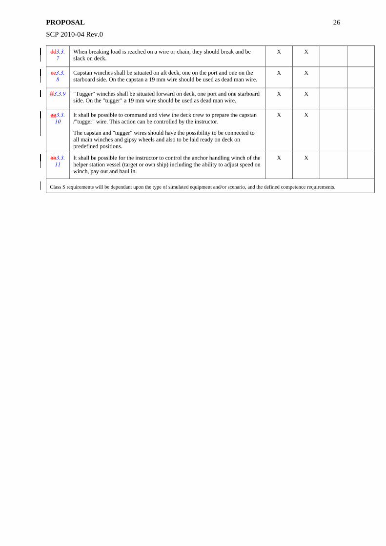
dd3.3.7
When breaking load is reached on a wire or chain, they should break and be slack on deck.
X X
ee3.3.8
Capstan winches shall be situated on aft deck, one on the port and one on the starboard side. On the capstan a 19 mm wire should be used as dead man wire.
X X
ff3.3.9 "Tugger" winches shall be situated forward on deck, one port and one starboard side. On the "tugger" a 19 mm wire should be used as dead man wire.
X X
gg3.3.10
It shall be possible to command and view the deck crew to prepare the capstan /"tugger" wire. This action can be controlled by the instructor. The capstan and "tugger" wires should have the possibility to be connected to all main winches and gipsy wheels and also to be laid ready on deck on predefined positions.
X X
hh3.3.11
It shall be possible for the instructor to control the anchor handling winch of the helper station vessel (target or own ship) including the ability to adjust speed on winch, pay out and haul in.
X X
Class S requirements will be dependant upon the type of simulated equipment and/or scenario, and the defined competence requirements.
PROPOSAL
SCP 2010-04 Rev.0
27
Section 4 - Machinery Operation
A. Simulator Class - Machinery Operation
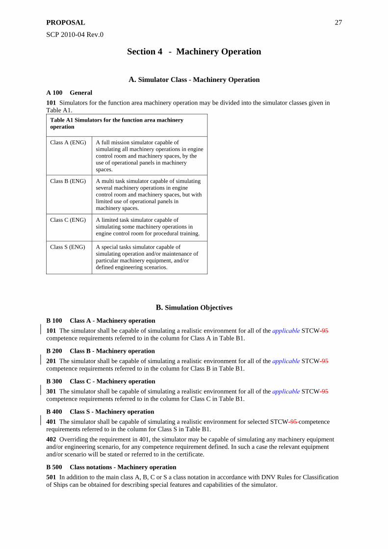
A 100 General 101 Simulators for the function area machinery operation may be divided into the simulator classes given in Table A1.
Table A1 Simulators for the function area machinery operation
Class A (ENG) A full mission simulator capable of simulating all machinery operations in engine control room and machinery spaces, by the use of operational panels in machinery spaces.
Class B (ENG) A multi task simulator capable of simulating several machinery operations in engine control room and machinery spaces, but with limited use of operational panels in machinery spaces.
Class C (ENG) A limited task simulator capable of simulating some machinery operations in engine control room for procedural training.
Class S (ENG) A special tasks simulator capable of simulating operation and/or maintenance of particular machinery equipment, and/or defined engineering scenarios.
B. Simulation Objectives
B 100 Class A - Machinery operation 101 The simulator shall be capable of simulating a realistic environment for all of the applicable STCW-95 competence requirements referred to in the column for Class A in Table B1.
B 200 Class B - Machinery operation 201 The simulator shall be capable of simulating a realistic environment for all of the applicable STCW-95 competence requirements referred to in the column for Class B in Table B1.
B 300 Class C - Machinery operation 301 The simulator shall be capable of simulating a realistic environment for all of the applicable STCW-95 competence requirements referred to in the column for Class C in Table B1.
B 400 Class S - Machinery operation 401 The simulator shall be capable of simulating a realistic environment for selected STCW-95 competence requirements referred to in the column for Class S in Table B1. 402 Overriding the requirement in 401, the simulator may be capable of simulating any machinery equipment and/or engineering scenario, for any competence requirement defined. In such a case the relevant equipment and/or scenario will be stated or referred to in the certificate.
B 500 Class notations - Machinery operation 501 In addition to the main class A, B, C or S a class notation in accordance with DNV Rules for Classification of Ships can be obtained for describing special features and capabilities of the simulator.
PROPOSAL
SCP 2010-04 Rev.0
28
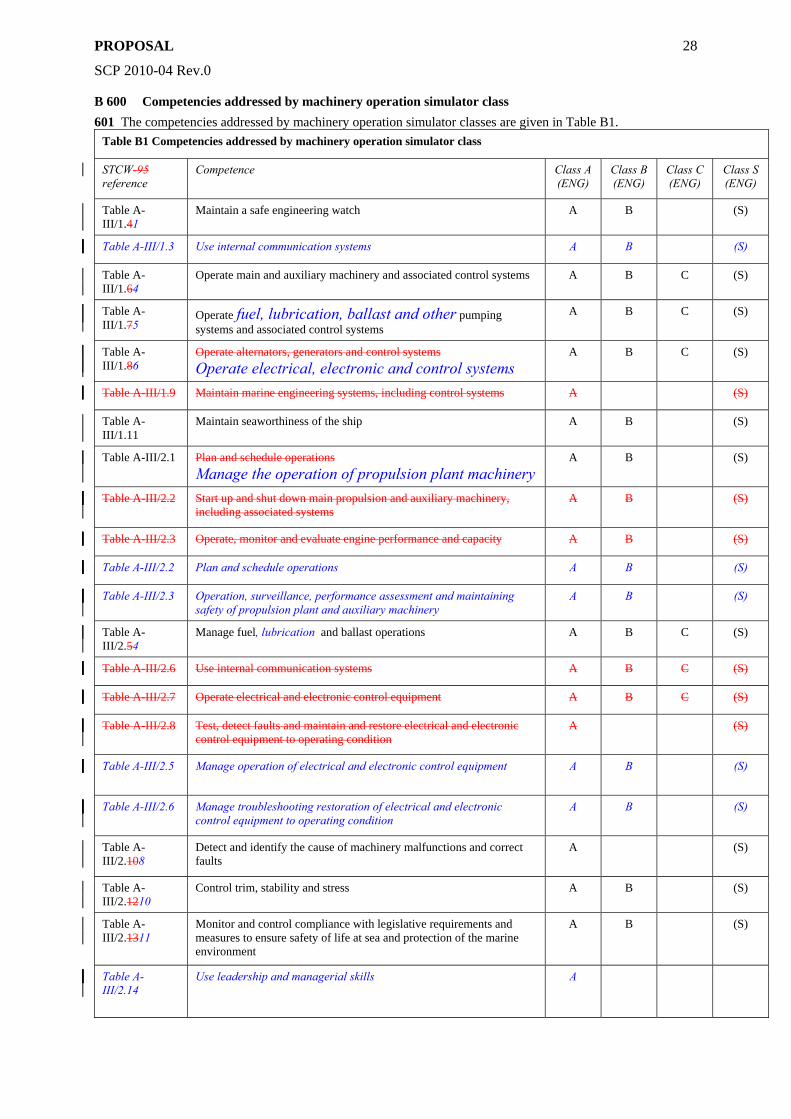
B 600 Competencies addressed by machinery operation simulator class 601 The competencies addressed by machinery operation simulator classes are given in Table B1.
Table B1 Competencies addressed by machinery operation simulator class
STCW-95 reference
Competence Class A (ENG)
Class B (ENG)
Class C (ENG)
Class S (ENG)
Table A-III/1.41
Maintain a safe engineering watch A B (S)
Table A-III/1.3 Use internal communication systems A B (S)
Table A-III/1.64
Operate main and auxiliary machinery and associated control systems A B C (S)
Table A-III/1.75
Operate fuel, lubrication, ballast and other pumping systems and associated control systems
A B C (S)
Table A-III/1.86
Operate alternators, generators and control systems Operate electrical, electronic and control systems
A B C (S)
Table A-III/1.9 Maintain marine engineering systems, including control systems A (S)
Table A-III/1.11
Maintain seaworthiness of the ship A B (S)
Table A-III/2.1 Plan and schedule operations Manage the operation of propulsion plant machinery
A B (S)
Table A-III/2.2 Start up and shut down main propulsion and auxiliary machinery, including associated systems
A B (S)
Table A-III/2.3 Operate, monitor and evaluate engine performance and capacity A B (S)
Table A-III/2.2 Plan and schedule operations A B (S)
Table A-III/2.3 Operation, surveillance, performance assessment and maintaining safety of propulsion plant and auxiliary machinery
A B (S)
Table A-III/2.54
Manage fuel, lubrication and ballast operations A B C (S)
Table A-III/2.6 Use internal communication systems A B C (S)
Table A-III/2.7 Operate electrical and electronic control equipment A B C (S)
Table A-III/2.8 Test, detect faults and maintain and restore electrical and electronic control equipment to operating condition
A (S)
Table A-III/2.5 Manage operation of electrical and electronic control equipment A B (S)
Table A-III/2.6 Manage troubleshooting restoration of electrical and electronic control equipment to operating condition
A B (S)
Table A-III/2.108
Detect and identify the cause of machinery malfunctions and correct faults
A (S)
Table A-III/2.1210
Control trim, stability and stress A B (S)
Table A-III/2.1311
Monitor and control compliance with legislative requirements and measures to ensure safety of life at sea and protection of the marine environment
A B (S)
Table A-III/2.14
Use leadership and managerial skills A
PROPOSAL
SCP 2010-04 Rev.0
29
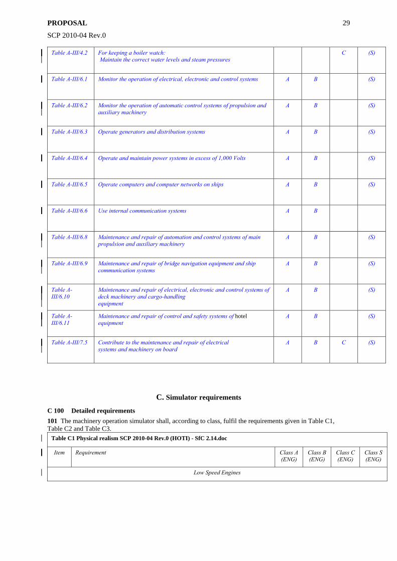
Table A-III/4.2 For keeping a boiler watch: Maintain the correct water levels and steam pressures
C (S)
Table A-III/6.1 Monitor the operation of electrical, electronic and control systems A B (S)
Table A-III/6.2 Monitor the operation of automatic control systems of propulsion and auxiliary machinery
A B (S)
Table A-III/6.3 Operate generators and distribution systems A B (S)
Table A-III/6.4 Operate and maintain power systems in excess of 1,000 Volts A B (S)
Table A-III/6.5 Operate computers and computer networks on ships A B (S)
Table A-III/6.6 Use internal communication systems A B
Table A-III/6.8 Maintenance and repair of automation and control systems of main propulsion and auxiliary machinery
A B (S)
Table A-III/6.9 Maintenance and repair of bridge navigation equipment and ship communication systems
A B (S)
Table A-III/6.10
Maintenance and repair of electrical, electronic and control systems of deck machinery and cargo-handling equipment
A B (S)
Table A-III/6.11
Maintenance and repair of control and safety systems of hotel equipment
A B (S)
Table A-III/7.5 Contribute to the maintenance and repair of electrical systems and machinery on board
A B C (S)
C. Simulator requirements
C 100 Detailed requirements 101 The machinery operation simulator shall, according to class, fulfil the requirements given in Table C1, Table C2 and Table C3.
Table C1 Physical realism SCP 2010-04 Rev.0 (HOTI) - SfC 2.14.doc
Item Requirement Class A (ENG)
Class B (ENG)
Class C (ENG)
Class S (ENG)
Low Speed Engines
PROPOSAL
SCP 2010-04 Rev.0
30
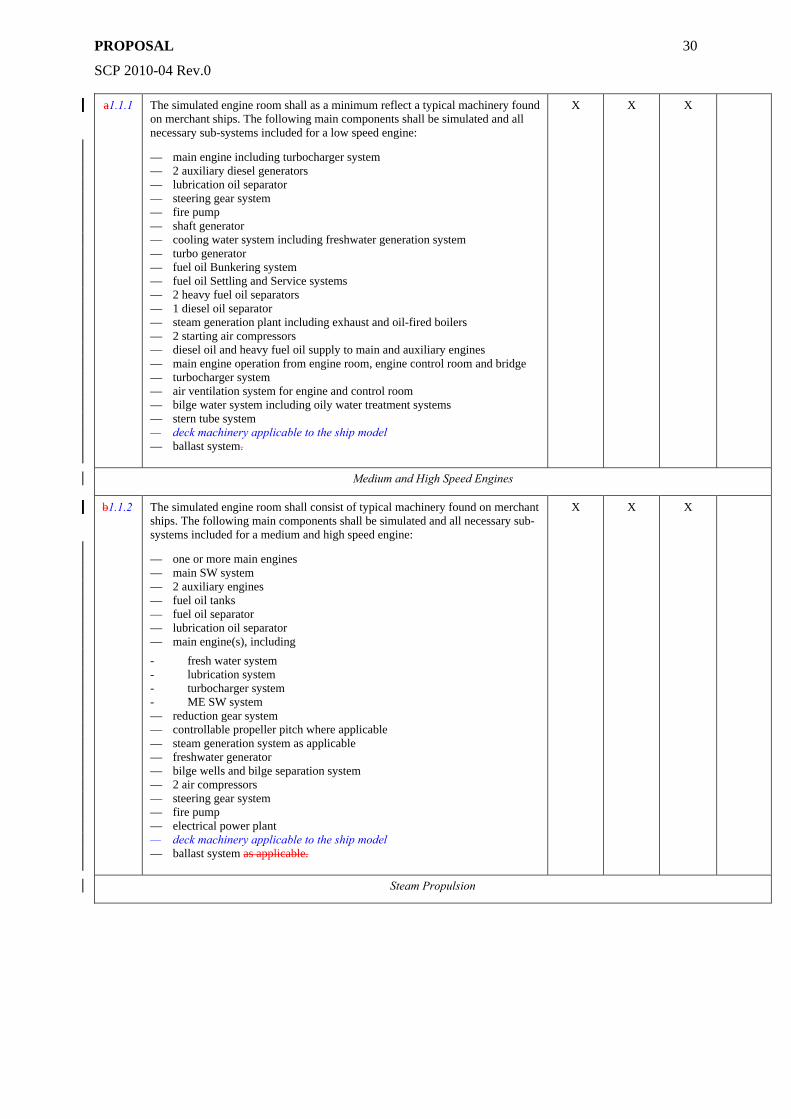
a1.1.1 The simulated engine room shall as a minimum reflect a typical machinery found on merchant ships. The following main components shall be simulated and all necessary sub-systems included for a low speed engine:
— main engine including turbocharger system — 2 auxiliary diesel generators — lubrication oil separator — steering gear system — fire pump — shaft generator — cooling water system including freshwater generation system — turbo generator — fuel oil Bunkering system — fuel oil Settling and Service systems — 2 heavy fuel oil separators — 1 diesel oil separator — steam generation plant including exhaust and oil-fired boilers — 2 starting air compressors — diesel oil and heavy fuel oil supply to main and auxiliary engines — main engine operation from engine room, engine control room and bridge — turbocharger system — air ventilation system for engine and control room — bilge water system including oily water treatment systems — stern tube system — deck machinery applicable to the ship model — ballast system.
X X X
Medium and High Speed Engines
b1.1.2 The simulated engine room shall consist of typical machinery found on merchant ships. The following main components shall be simulated and all necessary sub-systems included for a medium and high speed engine:
— one or more main engines — main SW system — 2 auxiliary engines — fuel oil tanks — fuel oil separator — lubrication oil separator — main engine(s), including - fresh water system - lubrication system - turbocharger system - ME SW system — reduction gear system — controllable propeller pitch where applicable — steam generation system as applicable — freshwater generator — bilge wells and bilge separation system — 2 air compressors — steering gear system — fire pump — electrical power plant — deck machinery applicable to the ship model — ballast system as applicable.
X X X
Steam Propulsion
PROPOSAL
SCP 2010-04 Rev.0
31
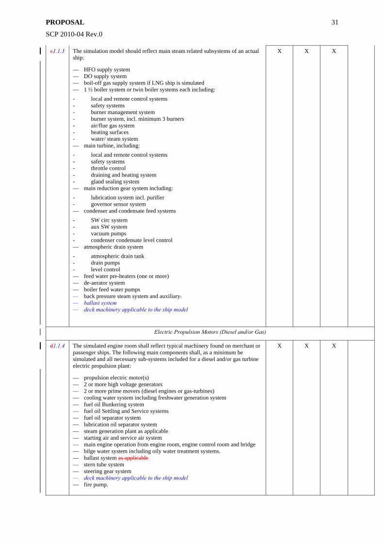
c1.1.3 The simulation model should reflect main steam related subsystems of an actual ship:
— HFO supply system — DO supply system — boil-off gas supply system if LNG ship is simulated — 1 ½ boiler system or twin boiler systems each including: - local and remote control systems - safety systems - burner management system - burner system, incl. minimum 3 burners - air/flue gas system - heating surfaces - water/ steam system — main turbine, including: - local and remote control systems - safety systems - throttle control - draining and heating system - gland sealing system — main reduction gear system including: - lubrication system incl. purifier - governor sensor system — condenser and condensate feed systems - SW circ system - aux SW system - vacuum pumps - condenser condensate level control — atmospheric drain system - atmospheric drain tank - drain pumps - level control — feed water pre-heaters (one or more) — de-aerator system — boiler feed water pumps — back pressure steam system and auxiliary. — ballast system — deck machinery applicable to the ship model
X X X
Electric Propulsion Motors (Diesel and/or Gas)
d1.1.4 The simulated engine room shall reflect typical machinery found on merchant or passenger ships. The following main components shall, as a minimum be simulated and all necessary sub-systems included for a diesel and/or gas turbine electric propulsion plant:
— propulsion electric motor(s) — 2 or more high voltage generators — 2 or more prime movers (diesel engines or gas-turbines) — cooling water system including freshwater generation system — fuel oil Bunkering system — fuel oil Settling and Service systems — fuel oil separator system — lubrication oil separator system — steam generation plant as applicable — starting air and service air system — main engine operation from engine room, engine control room and bridge — bilge water system including oily water treatment systems. — ballast system as applicable — stern tube system — steering gear system — deck machinery applicable to the ship model — fire pump.
X X X
PROPOSAL
SCP 2010-04 Rev.0
32
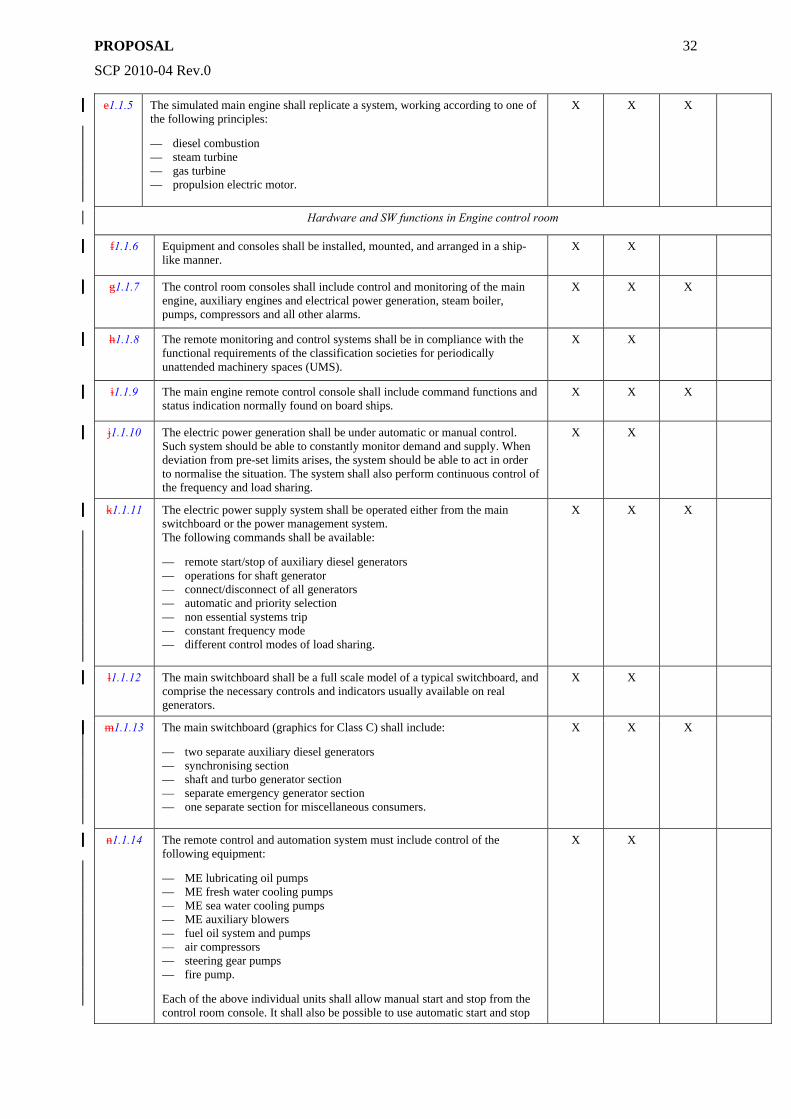
e1.1.5 The simulated main engine shall replicate a system, working according to one of the following principles:
— diesel combustion — steam turbine — gas turbine — propulsion electric motor.
X X X
Hardware and SW functions in Engine control room
f1.1.6 Equipment and consoles shall be installed, mounted, and arranged in a ship-like manner.
X X
g1.1.7 The control room consoles shall include control and monitoring of the main engine, auxiliary engines and electrical power generation, steam boiler, pumps, compressors and all other alarms.
X X X
h1.1.8 The remote monitoring and control systems shall be in compliance with the functional requirements of the classification societies for periodically unattended machinery spaces (UMS).
X X
i1.1.9 The main engine remote control console shall include command functions and status indication normally found on board ships.
X X X
j1.1.10 The electric power generation shall be under automatic or manual control. Such system should be able to constantly monitor demand and supply. When deviation from pre-set limits arises, the system should be able to act in order to normalise the situation. The system shall also perform continuous control of the frequency and load sharing.
X X
k1.1.11 The electric power supply system shall be operated either from the main switchboard or the power management system. The following commands shall be available:
— remote start/stop of auxiliary diesel generators — operations for shaft generator — connect/disconnect of all generators — automatic and priority selection — non essential systems trip — constant frequency mode — different control modes of load sharing.
X X X
l1.1.12 The main switchboard shall be a full scale model of a typical switchboard, and comprise the necessary controls and indicators usually available on real generators.
X X
m1.1.13 The main switchboard (graphics for Class C) shall include:
— two separate auxiliary diesel generators — synchronising section — shaft and turbo generator section — separate emergency generator section — one separate section for miscellaneous consumers.
X X X
n1.1.14 The remote control and automation system must include control of the following equipment:
— ME lubricating oil pumps — ME fresh water cooling pumps — ME sea water cooling pumps — ME auxiliary blowers — fuel oil system and pumps — air compressors — steering gear pumps — fire pump.
Each of the above individual units shall allow manual start and stop from the control room console. It shall also be possible to use automatic start and stop
X X
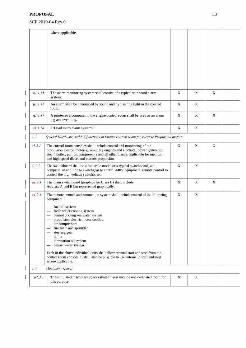
PROPOSAL
SCP 2010-04 Rev.0
33
where applicable.
o1.1.15 The alarm monitoring system shall consist of a typical shipboard alarm system.
X X X
p1.1.16 An alarm shall be announced by sound and by flashing light in the control room.
X X
q1.1.17 A printer or a computer in the engine control room shall be used as an alarm log and event log.
X X X
r1.1.18 "“Dead mans alarm system"” X X
1.2 Special Hardware and SW functions in Engine control room for Electric Propulsion motors
s1.2.1 The control room consoles shall include control and monitoring of the propulsion electric motor(s), auxiliary engines and electrical power generation, steam boiler, pumps, compressors and all other alarms applicable for medium and high speed diesel and electric propulsion.
X X X
t1.2.2 The switchboard shall be a full scale model of a typical switchboard, and comprise, in addition to switchgear to control 440V equipment, remote control to control the high voltage switchboard.
X X
u1.2.3 The main switchboard (graphics for Class C) shall include: As class A and B but represented graphically.
X X X
v1.2.4 The remote control and automation system shall include control of the following equipment:
— fuel oil system — fresh water cooling system — central cooling sea water system — propulsion electric motor cooling — air compressors — fire main and sprinkler — steering gear — boiler — lubrication oil system — ballast water system
Each of the above individual units shall allow manual start and stop from the control room console. It shall also be possible to use automatic start and stop where applicable.
X X
1.3 Machinery spaces
w1.3.1 The simulated machinery spaces shall at least include one dedicated room for this purpose.
X X
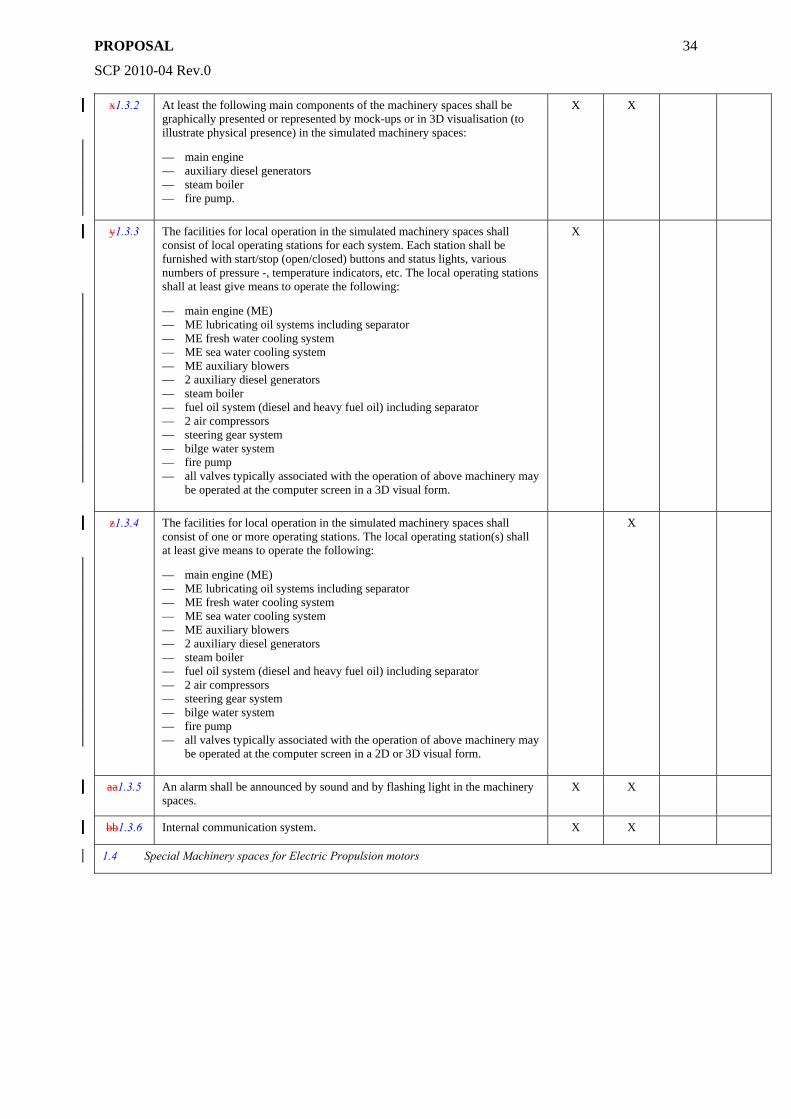
PROPOSAL
SCP 2010-04 Rev.0
34
x1.3.2 At least the following main components of the machinery spaces shall be graphically presented or represented by mock-ups or in 3D visualisation (to illustrate physical presence) in the simulated machinery spaces:
— main engine — auxiliary diesel generators — steam boiler — fire pump.
X X
y1.3.3 The facilities for local operation in the simulated machinery spaces shall consist of local operating stations for each system. Each station shall be furnished with start/stop (open/closed) buttons and status lights, various numbers of pressure -, temperature indicators, etc. The local operating stations shall at least give means to operate the following:
— main engine (ME) — ME lubricating oil systems including separator — ME fresh water cooling system — ME sea water cooling system — ME auxiliary blowers — 2 auxiliary diesel generators — steam boiler — fuel oil system (diesel and heavy fuel oil) including separator — 2 air compressors — steering gear system — bilge water system — fire pump — all valves typically associated with the operation of above machinery may
be operated at the computer screen in a 3D visual form.
X
z1.3.4 The facilities for local operation in the simulated machinery spaces shall consist of one or more operating stations. The local operating station(s) shall at least give means to operate the following:
— main engine (ME) — ME lubricating oil systems including separator — ME fresh water cooling system — ME sea water cooling system — ME auxiliary blowers — 2 auxiliary diesel generators — steam boiler — fuel oil system (diesel and heavy fuel oil) including separator — 2 air compressors — steering gear system — bilge water system — fire pump — all valves typically associated with the operation of above machinery may
be operated at the computer screen in a 2D or 3D visual form.
X
aa1.3.5 An alarm shall be announced by sound and by flashing light in the machinery spaces.
X X
bb1.3.6 Internal communication system. X X
1.4 Special Machinery spaces for Electric Propulsion motors
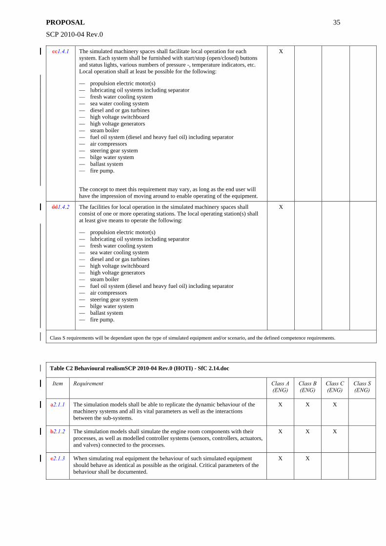
PROPOSAL
SCP 2010-04 Rev.0
35
cc1.4.1 The simulated machinery spaces shall facilitate local operation for each system. Each system shall be furnished with start/stop (open/closed) buttons and status lights, various numbers of pressure -, temperature indicators, etc. Local operation shall at least be possible for the following:
— propulsion electric motor(s) — lubricating oil systems including separator — fresh water cooling system — sea water cooling system — diesel and or gas turbines — high voltage switchboard — high voltage generators — steam boiler — fuel oil system (diesel and heavy fuel oil) including separator — air compressors — steering gear system — bilge water system — ballast system — fire pump.
The concept to meet this requirement may vary, as long as the end user will have the impression of moving around to enable operating of the equipment.
X
dd1.4.2 The facilities for local operation in the simulated machinery spaces shall consist of one or more operating stations. The local operating station(s) shall at least give means to operate the following:
— propulsion electric motor(s) — lubricating oil systems including separator — fresh water cooling system — sea water cooling system — diesel and or gas turbines — high voltage switchboard — high voltage generators — steam boiler — fuel oil system (diesel and heavy fuel oil) including separator — air compressors — steering gear system — bilge water system — ballast system — fire pump.
X
Class S requirements will be dependant upon the type of simulated equipment and/or scenario, and the defined competence requirements.
Table C2 Behavioural realismSCP 2010-04 Rev.0 (HOTI) - SfC 2.14.doc
Item Requirement Class A (ENG)
Class B (ENG)
Class C (ENG)
Class S (ENG)
a2.1.1 The simulation models shall be able to replicate the dynamic behaviour of the machinery systems and all its vital parameters as well as the interactions between the sub-systems.
X X X
b2.1.2 The simulation models shall simulate the engine room components with their processes, as well as modelled controller systems (sensors, controllers, actuators, and valves) connected to the processes.
X X X
c2.1.3 When simulating real equipment the behaviour of such simulated equipment should behave as identical as possible as the original. Critical parameters of the behaviour shall be documented.
X X
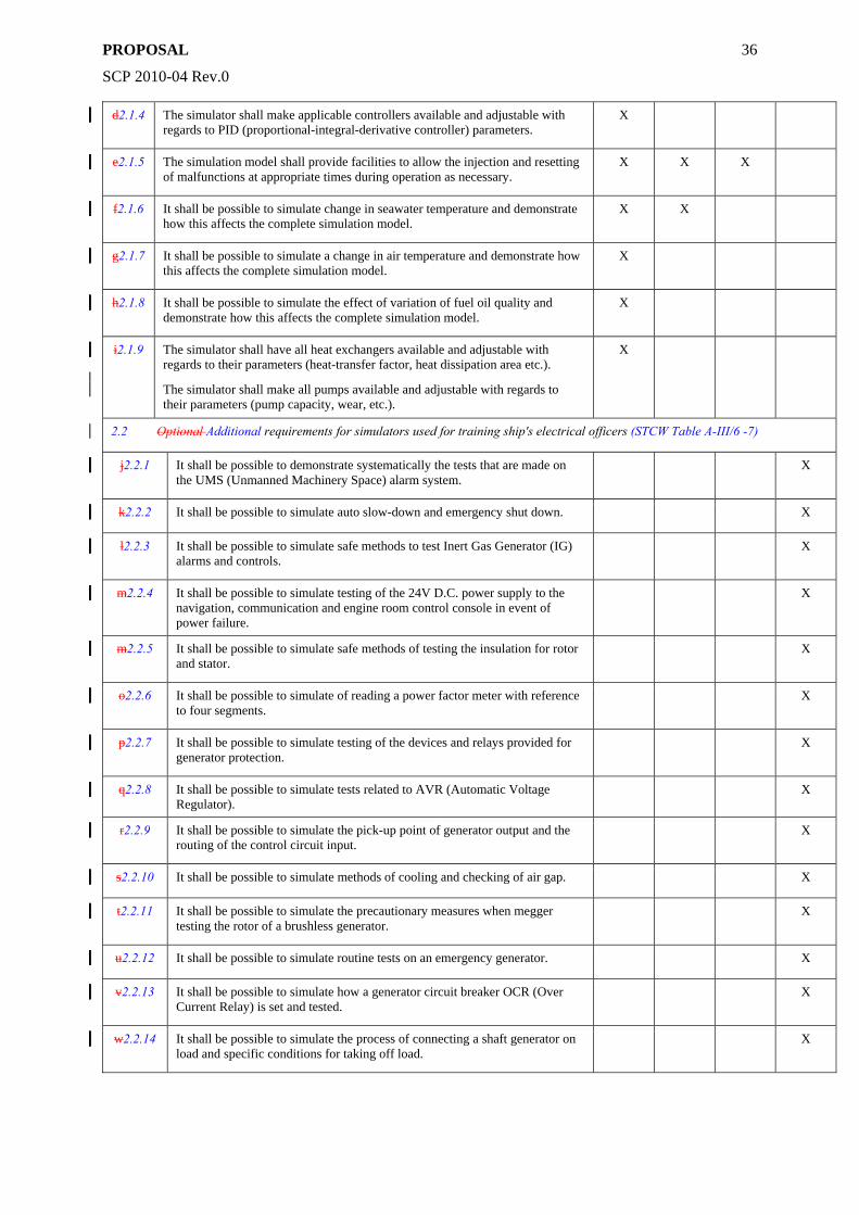
PROPOSAL
SCP 2010-04 Rev.0
36
d2.1.4 The simulator shall make applicable controllers available and adjustable with regards to PID (proportional-integral-derivative controller) parameters.
X
e2.1.5 The simulation model shall provide facilities to allow the injection and resetting of malfunctions at appropriate times during operation as necessary.
X X X
f2.1.6 It shall be possible to simulate change in seawater temperature and demonstrate how this affects the complete simulation model.
X X
g2.1.7 It shall be possible to simulate a change in air temperature and demonstrate how this affects the complete simulation model.
X
h2.1.8 It shall be possible to simulate the effect of variation of fuel oil quality and demonstrate how this affects the complete simulation model.
X
i2.1.9 The simulator shall have all heat exchangers available and adjustable with regards to their parameters (heat-transfer factor, heat dissipation area etc.). The simulator shall make all pumps available and adjustable with regards to their parameters (pump capacity, wear, etc.).
X
2.2 Optional Additional requirements for simulators used for training ship's electrical officers (STCW Table A-III/6 -7)
j2.2.1 It shall be possible to demonstrate systematically the tests that are made on the UMS (Unmanned Machinery Space) alarm system.
X
k2.2.2 It shall be possible to simulate auto slow-down and emergency shut down. X
l2.2.3 It shall be possible to simulate safe methods to test Inert Gas Generator (IG) alarms and controls.
X
m2.2.4 It shall be possible to simulate testing of the 24V D.C. power supply to the navigation, communication and engine room control console in event of power failure.
X
m2.2.5 It shall be possible to simulate safe methods of testing the insulation for rotor and stator.
X
o2.2.6 It shall be possible to simulate of reading a power factor meter with reference to four segments.
X
p2.2.7 It shall be possible to simulate testing of the devices and relays provided for generator protection.
X
q2.2.8 It shall be possible to simulate tests related to AVR (Automatic Voltage Regulator).
X
r2.2.9 It shall be possible to simulate the pick-up point of generator output and the routing of the control circuit input.
X
s2.2.10 It shall be possible to simulate methods of cooling and checking of air gap. X
t2.2.11 It shall be possible to simulate the precautionary measures when megger testing the rotor of a brushless generator.
X
u2.2.12 It shall be possible to simulate routine tests on an emergency generator. X
v2.2.13 It shall be possible to simulate how a generator circuit breaker OCR (Over Current Relay) is set and tested.
X
w2.2.14 It shall be possible to simulate the process of connecting a shaft generator on load and specific conditions for taking off load.
X
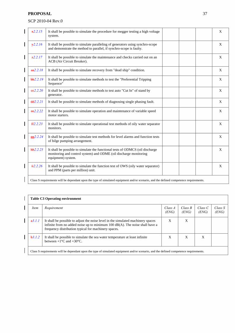
PROPOSAL
SCP 2010-04 Rev.0
37
x2.2.15 It shall be possible to simulate the procedure for megger testing a high voltage system.
X
y2.2.16 It shall be possible to simulate paralleling of generators using synchro-scope and demonstrate the method to parallel, if synchro-scope is faulty.
X
z2.2.17 It shall be possible to simulate the maintenance and checks carried out on an ACB (Air Circuit Breaker).
X
aa2.2.18 It shall be possible to simulate recovery from "dead ship" condition. X
bb2.2.19 It shall be possible to simulate methods to test the "Preferential Tripping Sequence"
X
cc2.2.20 It shall be possible to simulate methods to test auto "Cut In" of stand by generator.
X
dd2.2.21 It shall be possible to simulate methods of diagnosing single phasing fault. X
ee2.2.22 It shall be possible to simulate operation and maintenance of variable speed motor starters.
X
ff2.2.23 It shall be possible to simulate operational test methods of oily water separator monitors.
X
gg2.2.24 It shall be possible to simulate test methods for level alarms and function tests of bilge pumping arrangement.
X
hh2.2.25 It shall be possible to simulate the functional tests of ODMCS (oil discharge monitoring and control system) and ODME (oil discharge monitoring equipment) system.
X
ii2.2.26 It shall be possible to simulate the function test of OWS (oily water separator) and PPM (parts per million) unit.
X
Class S requirements will be dependant upon the type of simulated equipment and/or scenario, and the defined competence requirements.
Table C3 Operating environment
Item Requirement Class A (ENG)
Class B (ENG)
Class C (ENG)
Class S (ENG)
a3.1.1 It shall be possible to adjust the noise level in the simulated machinery spaces infinite from no added noise up to minimum 100 dB(A). The noise shall have a frequency distribution typical for machinery spaces.
X X
b3.1.2 It shall be possible to simulate the sea water temperature at least infinite between +1°C and +30°C.
X X X
Class S requirements will be dependant upon the type of simulated equipment and/or scenario, and the defined competence requirements.
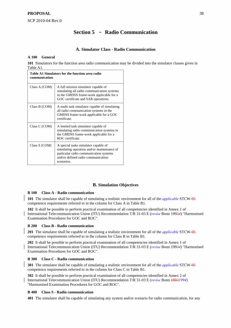
PROPOSAL
SCP 2010-04 Rev.0
38
Section 5 - Radio Communication
A. Simulator Class - Radio Communication
A 100 General 101 Simulators for the function area radio communication may be divided into the simulator classes given in Table A1.
Table A1 Simulators for the function area radio communication
Class A (COM) A full mission simulator capable of simulating all radio communication systems in the GMDSS frame-work applicable for a GOC certificate and SAR operations.
Class B (COM) A multi task simulator capable of simulating all radio communication systems in the GMDSS frame-work applicable for a GOC certificate.
Class C (COM) A limited task simulator capable of simulating radio communication systems in the GMDSS frame-work applicable for a ROC certificate.
Class S (COM) A special tasks simulator capable of simulating operation and/or maintenance of particular radio communication systems and/or defined radio communication scenarios.
B. Simulation Objectives
B 100 Class A - Radio communication 101 The simulator shall be capable of simulating a realistic environment for all of the applicable STCW-95 competence requirements referred to in the column for Class A in Table B1. 102 It shall be possible to perform practical examination of all competencies identified in Annex 1 of International Telecommunication Union (ITU) Recommendation T/R 31-03 E (revise Bonn 19934) "Harmonised Examination Procedures for GOC and ROC".
B 200 Class B - Radio communication 201 The simulator shall be capable of simulating a realistic environment for all of the applicable STCW-95 competence requirements referred to in the column for Class B in Table B1. 202 It shall be possible to perform practical examination of all competencies identified in Annex 1 of International Telecommunication Union (ITU) Recommendation T/R 31-03 E (revise Bonn 19934) "Harmonised Examination Procedures for GOC and ROC".
B 300 Class C - Radio communication 301 The simulator shall be capable of simulating a realistic environment for all of the applicable STCW-95 competence requirements referred to in the column for Class C in Table B1. 302 It shall be possible to perform practical examination of all competencies identified in Annex 2 of International Telecommunication Union (ITU) Recommendation T/R 31-03 E (revise Bonn 19931994) "Harmonised Examination Procedures for GOC and ROC".
B 400 Class S - Radio communication 401 The simulator shall be capable of simulating any system and/or scenario for radio communication, for any
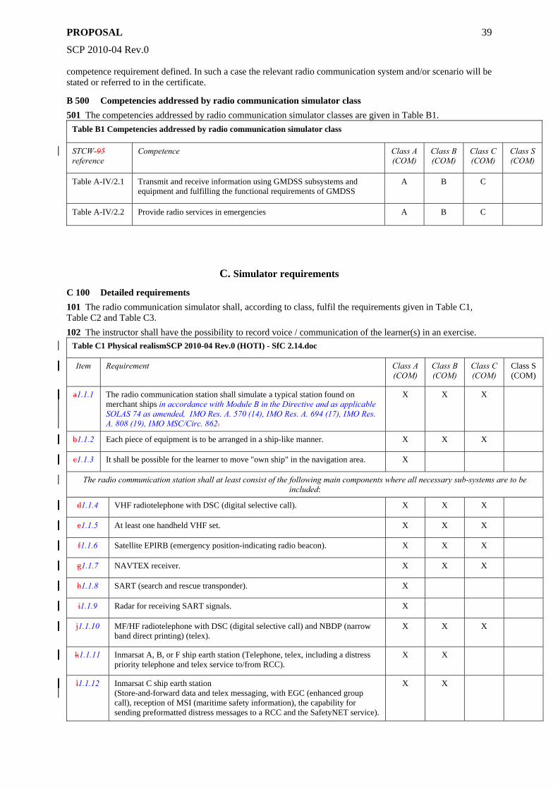
PROPOSAL
SCP 2010-04 Rev.0
39
competence requirement defined. In such a case the relevant radio communication system and/or scenario will be stated or referred to in the certificate.
B 500 Competencies addressed by radio communication simulator class 501 The competencies addressed by radio communication simulator classes are given in Table B1.
Table B1 Competencies addressed by radio communication simulator class
STCW-95 reference
Competence Class A (COM)
Class B (COM)
Class C (COM)
Class S (COM)
Table A-IV/2.1 Transmit and receive information using GMDSS subsystems and equipment and fulfilling the functional requirements of GMDSS
A B C
Table A-IV/2.2 Provide radio services in emergencies A B C
C. Simulator requirements
C 100 Detailed requirements 101 The radio communication simulator shall, according to class, fulfil the requirements given in Table C1, Table C2 and Table C3. 102 The instructor shall have the possibility to record voice / communication of the learner(s) in an exercise.
Table C1 Physical realismSCP 2010-04 Rev.0 (HOTI) - SfC 2.14.doc
Item Requirement Class A (COM)
Class B (COM)
Class C (COM)
Class S (COM)
a1.1.1 The radio communication station shall simulate a typical station found on merchant ships in accordance with Module B in the Directive and as applicable SOLAS 74 as amended, IMO Res. A. 570 (14), IMO Res. A. 694 (17), IMO Res. A. 808 (19), IMO MSC/Circ. 862.
X X X
b1.1.2 Each piece of equipment is to be arranged in a ship-like manner. X X X
c1.1.3 It shall be possible for the learner to move "own ship" in the navigation area. X
The radio communication station shall at least consist of the following main components where all necessary sub-systems are to be included:
d1.1.4 VHF radiotelephone with DSC (digital selective call). X X X
e1.1.5 At least one handheld VHF set. X X X
f1.1.6 Satellite EPIRB (emergency position-indicating radio beacon). X X X
g1.1.7 NAVTEX receiver. X X X
h1.1.8 SART (search and rescue transponder). X
i1.1.9 Radar for receiving SART signals. X
j1.1.10 MF/HF radiotelephone with DSC (digital selective call) and NBDP (narrow band direct printing) (telex).
X X X
k1.1.11 Inmarsat A, B, or F ship earth station (Telephone, telex, including a distress priority telephone and telex service to/from RCC).
X X
l1.1.12 Inmarsat C ship earth station (Store-and-forward data and telex messaging, with EGC (enhanced group call), reception of MSI (maritime safety information), the capability for sending preformatted distress messages to a RCC and the SafetyNET service).
X X
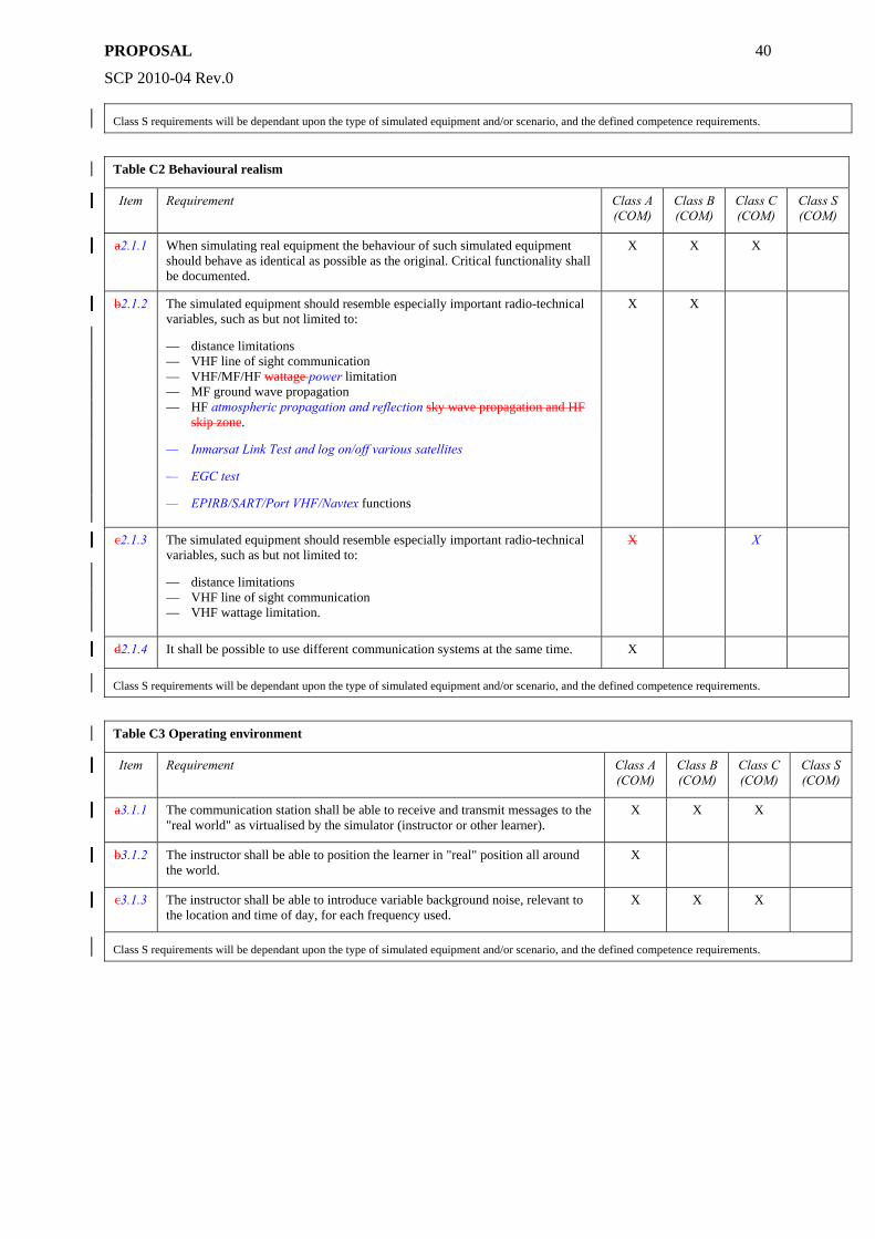
PROPOSAL
SCP 2010-04 Rev.0
40
Class S requirements will be dependant upon the type of simulated equipment and/or scenario, and the defined competence requirements.
Table C2 Behavioural realism
Item Requirement Class A (COM)
Class B (COM)
Class C (COM)
Class S (COM)
a2.1.1 When simulating real equipment the behaviour of such simulated equipment should behave as identical as possible as the original. Critical functionality shall be documented.
X X X
b2.1.2 The simulated equipment should resemble especially important radio-technical variables, such as but not limited to:
— distance limitations — VHF line of sight communication — VHF/MF/HF wattage power limitation — MF ground wave propagation — HF atmospheric propagation and reflection sky wave propagation and HF
skip zone.
— Inmarsat Link Test and log on/off various satellites
— EGC test
— EPIRB/SART/Port VHF/Navtex functions
X X
c2.1.3 The simulated equipment should resemble especially important radio-technical variables, such as but not limited to:
— distance limitations — VHF line of sight communication — VHF wattage limitation.
X X
d2.1.4 It shall be possible to use different communication systems at the same time. X
Class S requirements will be dependant upon the type of simulated equipment and/or scenario, and the defined competence requirements.
Table C3 Operating environment
Item Requirement Class A (COM)
Class B (COM)
Class C (COM)
Class S (COM)
a3.1.1 The communication station shall be able to receive and transmit messages to the "real world" as virtualised by the simulator (instructor or other learner).
X X X
b3.1.2 The instructor shall be able to position the learner in "real" position all around the world.
X
c3.1.3 The instructor shall be able to introduce variable background noise, relevant to the location and time of day, for each frequency used.
X X X
Class S requirements will be dependant upon the type of simulated equipment and/or scenario, and the defined competence requirements.
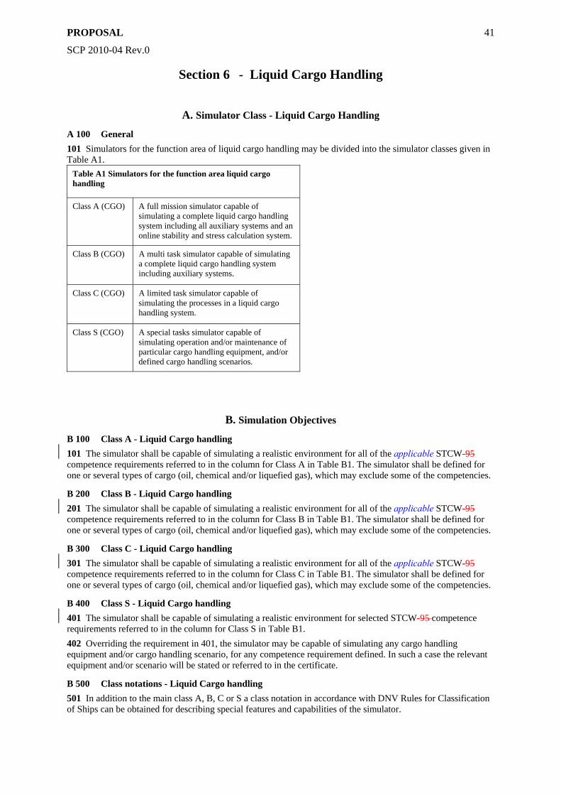
PROPOSAL
SCP 2010-04 Rev.0
41
Section 6 - Liquid Cargo Handling
A. Simulator Class - Liquid Cargo Handling
A 100 General 101 Simulators for the function area of liquid cargo handling may be divided into the simulator classes given in Table A1.
Table A1 Simulators for the function area liquid cargo handling
Class A (CGO) A full mission simulator capable of simulating a complete liquid cargo handling system including all auxiliary systems and an online stability and stress calculation system.
Class B (CGO) A multi task simulator capable of simulating a complete liquid cargo handling system including auxiliary systems.
Class C (CGO) A limited task simulator capable of simulating the processes in a liquid cargo handling system.
Class S (CGO) A special tasks simulator capable of simulating operation and/or maintenance of particular cargo handling equipment, and/or defined cargo handling scenarios.
B. Simulation Objectives
B 100 Class A - Liquid Cargo handling 101 The simulator shall be capable of simulating a realistic environment for all of the applicable STCW-95 competence requirements referred to in the column for Class A in Table B1. The simulator shall be defined for one or several types of cargo (oil, chemical and/or liquefied gas), which may exclude some of the competencies.
B 200 Class B - Liquid Cargo handling 201 The simulator shall be capable of simulating a realistic environment for all of the applicable STCW-95 competence requirements referred to in the column for Class B in Table B1. The simulator shall be defined for one or several types of cargo (oil, chemical and/or liquefied gas), which may exclude some of the competencies.
B 300 Class C - Liquid Cargo handling 301 The simulator shall be capable of simulating a realistic environment for all of the applicable STCW-95 competence requirements referred to in the column for Class C in Table B1. The simulator shall be defined for one or several types of cargo (oil, chemical and/or liquefied gas), which may exclude some of the competencies.
B 400 Class S - Liquid Cargo handling 401 The simulator shall be capable of simulating a realistic environment for selected STCW-95 competence requirements referred to in the column for Class S in Table B1. 402 Overriding the requirement in 401, the simulator may be capable of simulating any cargo handling equipment and/or cargo handling scenario, for any competence requirement defined. In such a case the relevant equipment and/or scenario will be stated or referred to in the certificate.
B 500 Class notations - Liquid Cargo handling 501 In addition to the main class A, B, C or S a class notation in accordance with DNV Rules for Classification of Ships can be obtained for describing special features and capabilities of the simulator.
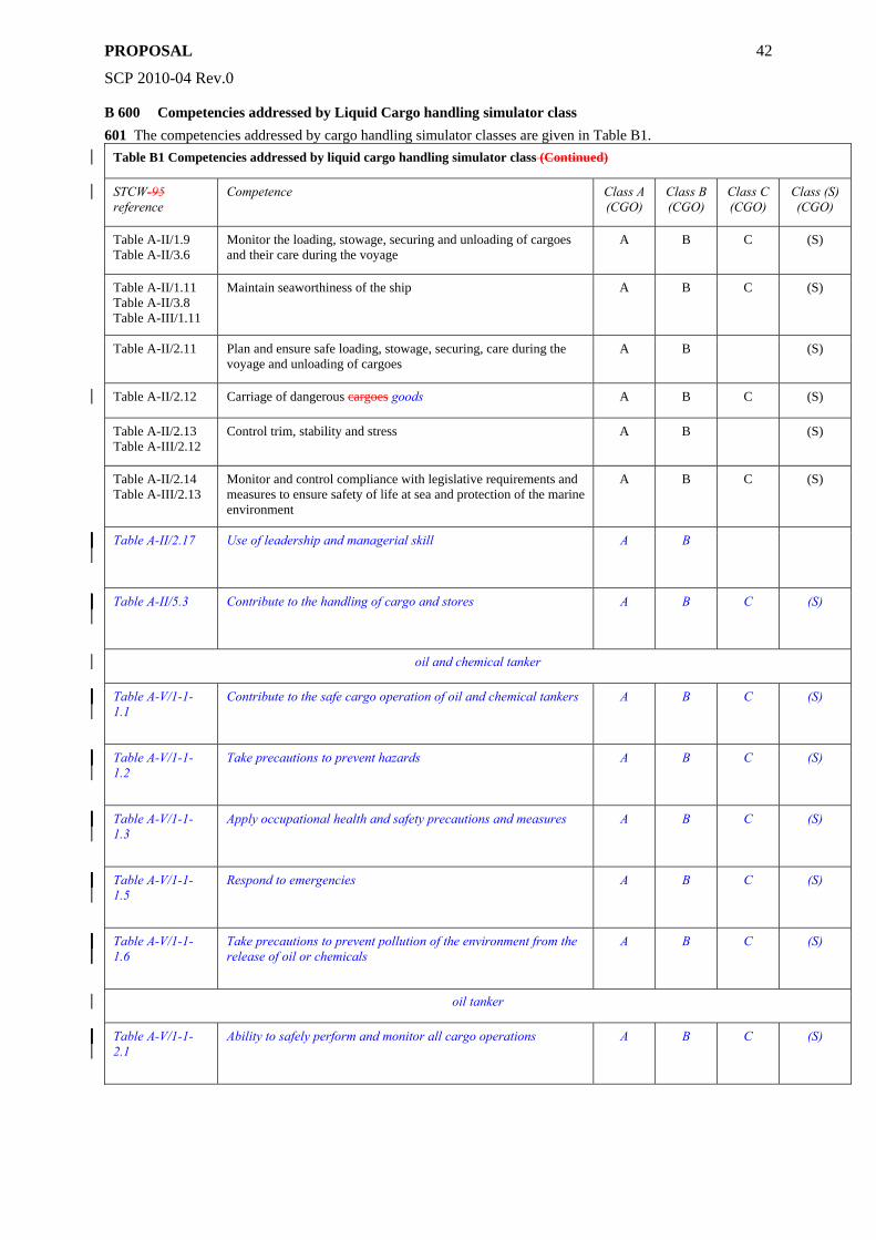
PROPOSAL
SCP 2010-04 Rev.0
42
B 600 Competencies addressed by Liquid Cargo handling simulator class 601 The competencies addressed by cargo handling simulator classes are given in Table B1.
Table B1 Competencies addressed by liquid cargo handling simulator class (Continued)
STCW-95 reference
Competence Class A (CGO)
Class B (CGO)
Class C (CGO)
Class (S) (CGO)
Table A-II/1.9 Table A-II/3.6
Monitor the loading, stowage, securing and unloading of cargoes and their care during the voyage
A B C (S)
Table A-II/1.11 Table A-II/3.8 Table A-III/1.11
Maintain seaworthiness of the ship A B C (S)
Table A-II/2.11 Plan and ensure safe loading, stowage, securing, care during the voyage and unloading of cargoes
A B (S)
Table A-II/2.12 Carriage of dangerous cargoes goods A B C (S)
Table A-II/2.13 Table A-III/2.12
Control trim, stability and stress A B (S)
Table A-II/2.14 Table A-III/2.13
Monitor and control compliance with legislative requirements and measures to ensure safety of life at sea and protection of the marine environment
A B C (S)
Table A-II/2.17
Use of leadership and managerial skill A B
Table A-II/5.3
Contribute to the handling of cargo and stores A B C (S)
oil and chemical tanker
Table A-V/1-1-1.1
Contribute to the safe cargo operation of oil and chemical tankers A B C (S)
Table A-V/1-1-1.2
Take precautions to prevent hazards A B C (S)
Table A-V/1-1-1.3
Apply occupational health and safety precautions and measures A B C (S)
Table A-V/1-1-1.5
Respond to emergencies A B C (S)
Table A-V/1-1-1.6
Take precautions to prevent pollution of the environment from the release of oil or chemicals
A B C (S)
oil tanker
Table A-V/1-1-2.1
Ability to safely perform and monitor all cargo operations A B C (S)
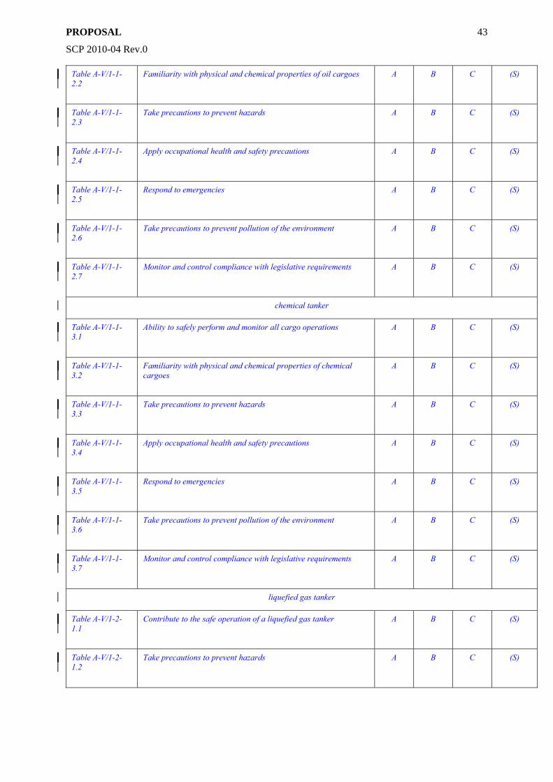
PROPOSAL
SCP 2010-04 Rev.0
43
Table A-V/1-1-2.2
Familiarity with physical and chemical properties of oil cargoes A B C (S)
Table A-V/1-1-2.3
Take precautions to prevent hazards A B C (S)
Table A-V/1-1-2.4
Apply occupational health and safety precautions A B C (S)
Table A-V/1-1-2.5
Respond to emergencies A B C (S)
Table A-V/1-1-2.6
Take precautions to prevent pollution of the environment A B C (S)
Table A-V/1-1-2.7
Monitor and control compliance with legislative requirements A B C (S)
chemical tanker
Table A-V/1-1-3.1
Ability to safely perform and monitor all cargo operations A B C (S)
Table A-V/1-1-3.2
Familiarity with physical and chemical properties of chemical cargoes
A B C (S)
Table A-V/1-1-3.3
Take precautions to prevent hazards A B C (S)
Table A-V/1-1-3.4
Apply occupational health and safety precautions A B C (S)
Table A-V/1-1-3.5
Respond to emergencies A B C (S)
Table A-V/1-1-3.6
Take precautions to prevent pollution of the environment A B C (S)
Table A-V/1-1-3.7
Monitor and control compliance with legislative requirements A B C (S)
liquefied gas tanker
Table A-V/1-2-1.1
Contribute to the safe operation of a liquefied gas tanker A B C (S)
Table A-V/1-2-1.2
Take precautions to prevent hazards A B C (S)
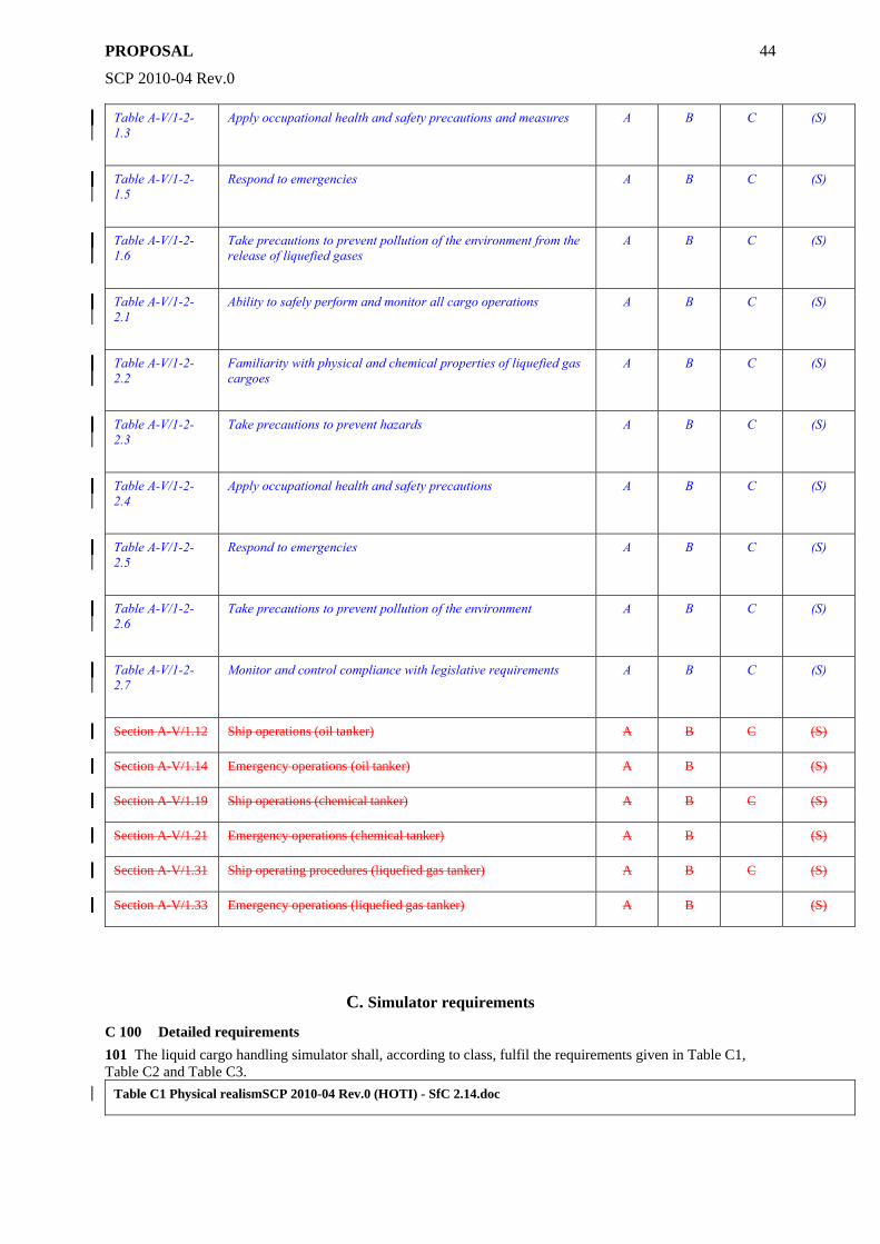
PROPOSAL
SCP 2010-04 Rev.0
44
Table A-V/1-2-1.3
Apply occupational health and safety precautions and measures A B C (S)
Table A-V/1-2-1.5
Respond to emergencies A B C (S)
Table A-V/1-2-1.6
Take precautions to prevent pollution of the environment from the release of liquefied gases
A B C (S)
Table A-V/1-2-2.1
Ability to safely perform and monitor all cargo operations A B C (S)
Table A-V/1-2-2.2
Familiarity with physical and chemical properties of liquefied gas cargoes
A B C (S)
Table A-V/1-2-2.3
Take precautions to prevent hazards A B C (S)
Table A-V/1-2-2.4
Apply occupational health and safety precautions A B C (S)
Table A-V/1-2-2.5
Respond to emergencies A B C (S)
Table A-V/1-2-2.6
Take precautions to prevent pollution of the environment A B C (S)
Table A-V/1-2-2.7
Monitor and control compliance with legislative requirements A B C (S)
Section A-V/1.12 Ship operations (oil tanker) A B C (S)
Section A-V/1.14 Emergency operations (oil tanker) A B (S)
Section A-V/1.19 Ship operations (chemical tanker) A B C (S)
Section A-V/1.21 Emergency operations (chemical tanker) A B (S)
Section A-V/1.31 Ship operating procedures (liquefied gas tanker) A B C (S)
Section A-V/1.33 Emergency operations (liquefied gas tanker) A B (S)
C. Simulator requirements
C 100 Detailed requirements 101 The liquid cargo handling simulator shall, according to class, fulfil the requirements given in Table C1, Table C2 and Table C3.
Table C1 Physical realismSCP 2010-04 Rev.0 (HOTI) - SfC 2.14.doc
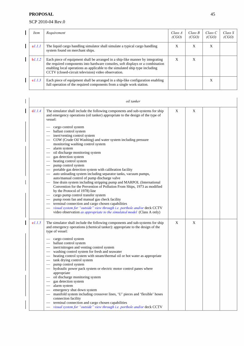
PROPOSAL
SCP 2010-04 Rev.0
45
Item Requirement Class A (CGO)
Class B (CGO)
Class C (CGO)
Class S (CGO)
a1.1.1 The liquid cargo handling simulator shall simulate a typical cargo handling system found on merchant ships.
X X X
b1.1.2 Each piece of equipment shall be arranged in a ship-like manner by integrating the required components into hardware consoles, soft displays or a combination enabling local operations as applicable to the simulated ship type including CCTV (closed-circuit television) video observation.
X X
c1.1.3 Each piece of equipment shall be arranged in a ship-like configuration enabling full operation of the required components from a single work station.
X
oil tanker
d1.1.4 The simulator shall include the following components and sub-systems for ship and emergency operations (oil tanker) appropriate to the design of the type of vessel:
— cargo control system — ballast control system — inert/venting control system — COW (Crude Oil Washing) and water system including pressure
monitoring washing control system — alarm system — oil discharge monitoring system — gas detection system — heating control system — pump control system — portable gas detection system with calibration facility — auto unloading system including separator tanks, vacuum pumps,
auto/manual control of pump discharge valve — line drain system including stripping pump and MARPOL (International
Convention for the Prevention of Pollution From Ships, 1973 as modified by the Protocol of 1978) line
— cargo pump control transfer system — pump room fan and manual gas check facility — terminal connection and cargo chosen capabilities — visual system for “outside” view through i.e. porthole and/or deck CCTV
video observation as appropriate to the simulated model (Class A only)
X X
e1.1.5 The simulator shall include the following components and sub-systems for ship and emergency operations (chemical tanker): appropriate to the design of the type of vessel:
— cargo control system — ballast control system — inert/nitrogen and venting control system — washing control system for fresh and seawater — heating control system with steam/thermal oil or hot water as appropriate — tank drying control system — pump control system — hydraulic power pack system or electric motor control panes where
appropriate — oil discharge monitoring system — gas detection system — alarm system — emergency shut down system — manifold system including crossover lines, ‘U’ pieces and ‘flexible’ hoses
connection facility — terminal connection and cargo chosen capabilities — visual system for “outside” view through i.e. porthole and/or deck CCTV
X X
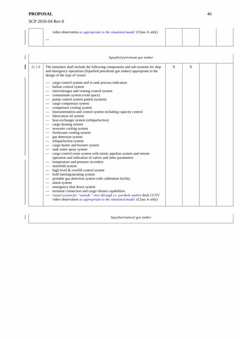
PROPOSAL
SCP 2010-04 Rev.0
46
video observation as appropriate to the simulated model (Class A only)
—
liquefied petroleum gas tanker
f1.1.6 The simulator shall include the following components and sub-systems for ship and emergency operations (liquefied petroleum gas tanker) appropriate to the design of the type of vessel:
— cargo control system and in tank process indication — ballast control system — inert/nitrogen and venting control system — contaminate system (void space) — pump control system panels (system) — cargo compressor system — compressor cooling system — Instrumentation and control system including capacity control — lubrication oil system — heat exchanger system (reliquefaction) — cargo heating system — seawater cooling system — freshwater cooling system — gas detection system — reliquefaction system — cargo heater and booster system — tank water spray system — cargo control room system with mimic pipeline system and remote
operation and indication of valves and other parameters — temperature and pressure recorders — manifold system — high level & overfill control system — hold inerting/aerating system — portable gas detection system with calibration facility — alarm system — emergency shut down system — terminal connection and cargo chosen capabilities — visual system for “outside” view through i.e. porthole and/or deck CCTV
video observation as appropriate to the simulated model (Class A only)
X X
liquefied natural gas tanker
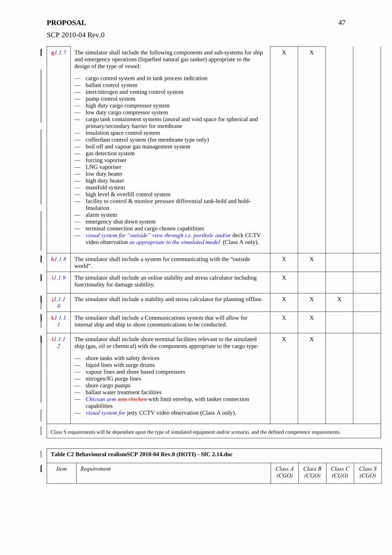
PROPOSAL
SCP 2010-04 Rev.0
47
g1.1.7 The simulator shall include the following components and sub-systems for ship and emergency operations (liquefied natural gas tanker) appropriate to the design of the type of vessel:
— cargo control system and in tank process indication — ballast control system — inert/nitrogen and venting control system — pump control system — high duty cargo compressor system — low duty cargo compressor system — cargo tank containment systems (anural and void space for spherical and
primary/secondary barrier for membrane — insulation space control system — cofferdam control system (for membrane type only) — boil off and vapour gas management system — gas detection system — forcing vaporiser — LNG vaporiser — low duty heater — high duty heater — manifold system — high level & overfill control system — facility to control & monitor pressure differential tank-hold and hold-
Insulation — alarm system — emergency shut down system — terminal connection and cargo chosen capabilities — visual system for “outside” view through i.e. porthole and/or deck CCTV
video observation as appropriate to the simulated model (Class A only).
X X
h1.1.8 The simulator shall include a system for communicating with the “outside world”.
X X
i1.1.9 The simulator shall include an online stability and stress calculator including functionality for damage stability.
X
j1.1.10
The simulator shall include a stability and stress calculator for planning offline. X X X
k1.1.11
The simulator shall include a Communications system that will allow for internal ship and ship to shore communications to be conducted.
X X
l1.1.12
The simulator shall include shore terminal facilities relevant to the simulated ship (gas, oil or chemical) with the components appropriate to the cargo type:
— shore tanks with safety devices — liquid lines with surge drums — vapour lines and shore based compressors — nitrogen/IG purge lines — shore cargo pumps — ballast water treatment facilities — Chicsan arm arm chicken with limit envelop, with tanker connection
capabilities — visual system for jetty CCTV video observation (Class A only).
X X
Class S requirements will be dependant upon the type of simulated equipment and/or scenario, and the defined competence requirements.
Table C2 Behavioural realismSCP 2010-04 Rev.0 (HOTI) - SfC 2.14.doc
Item Requirement Class A (CGO)
Class B (CGO)
Class C (CGO)
Class S (CGO)
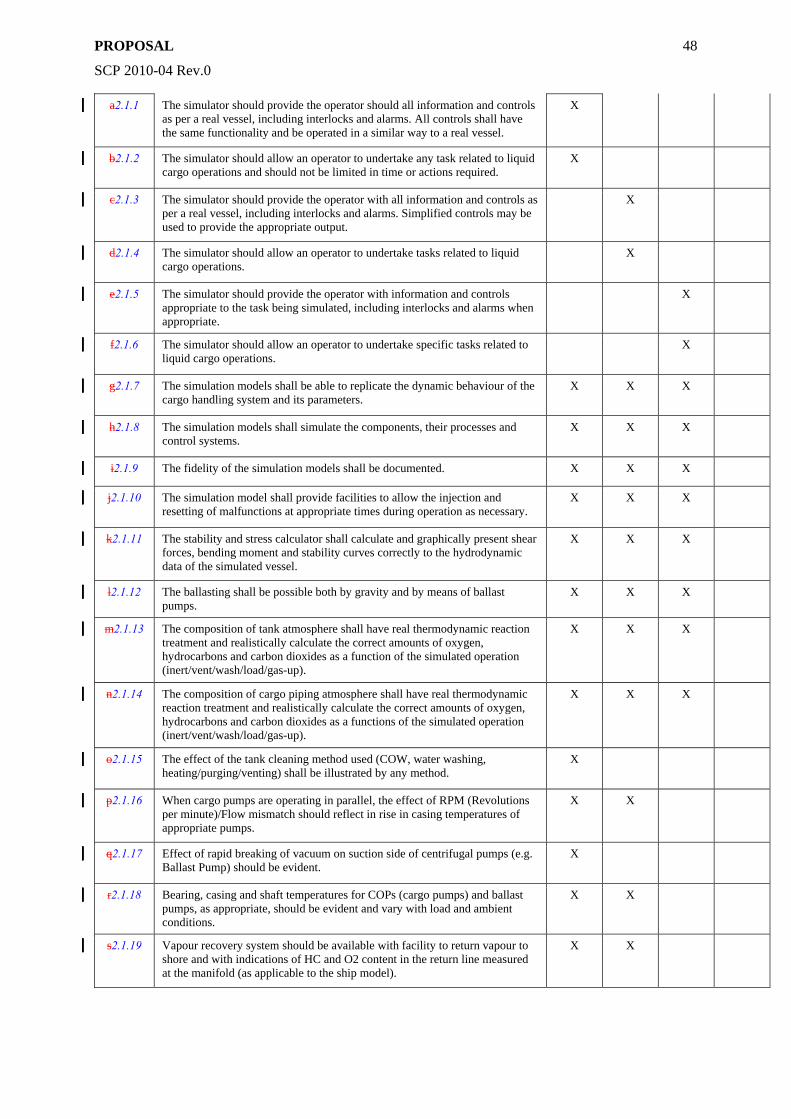
PROPOSAL
SCP 2010-04 Rev.0
48
a2.1.1 The simulator should provide the operator should all information and controls as per a real vessel, including interlocks and alarms. All controls shall have the same functionality and be operated in a similar way to a real vessel.
X
b2.1.2 The simulator should allow an operator to undertake any task related to liquid cargo operations and should not be limited in time or actions required.
X
c2.1.3 The simulator should provide the operator with all information and controls as per a real vessel, including interlocks and alarms. Simplified controls may be used to provide the appropriate output.
X
d2.1.4 The simulator should allow an operator to undertake tasks related to liquid cargo operations.
X
e2.1.5 The simulator should provide the operator with information and controls appropriate to the task being simulated, including interlocks and alarms when appropriate.
X
f2.1.6 The simulator should allow an operator to undertake specific tasks related to liquid cargo operations.
X
g2.1.7 The simulation models shall be able to replicate the dynamic behaviour of the cargo handling system and its parameters.
X X X
h2.1.8 The simulation models shall simulate the components, their processes and control systems.
X X X
i2.1.9 The fidelity of the simulation models shall be documented. X X X
j2.1.10 The simulation model shall provide facilities to allow the injection and resetting of malfunctions at appropriate times during operation as necessary.
X X X
k2.1.11 The stability and stress calculator shall calculate and graphically present shear forces, bending moment and stability curves correctly to the hydrodynamic data of the simulated vessel.
X X X
l2.1.12 The ballasting shall be possible both by gravity and by means of ballast pumps.
X X X
m2.1.13 The composition of tank atmosphere shall have real thermodynamic reaction treatment and realistically calculate the correct amounts of oxygen, hydrocarbons and carbon dioxides as a function of the simulated operation (inert/vent/wash/load/gas-up).
X X X
n2.1.14 The composition of cargo piping atmosphere shall have real thermodynamic reaction treatment and realistically calculate the correct amounts of oxygen, hydrocarbons and carbon dioxides as a functions of the simulated operation (inert/vent/wash/load/gas-up).
X X X
o2.1.15 The effect of the tank cleaning method used (COW, water washing, heating/purging/venting) shall be illustrated by any method.
X
p2.1.16 When cargo pumps are operating in parallel, the effect of RPM (Revolutions per minute)/Flow mismatch should reflect in rise in casing temperatures of appropriate pumps.
X X
q2.1.17 Effect of rapid breaking of vacuum on suction side of centrifugal pumps (e.g. Ballast Pump) should be evident.
X
r2.1.18 Bearing, casing and shaft temperatures for COPs (cargo pumps) and ballast pumps, as appropriate, should be evident and vary with load and ambient conditions.
X X
s2.1.19 Vapour recovery system should be available with facility to return vapour to shore and with indications of HC and O2 content in the return line measured at the manifold (as applicable to the ship model).
X X
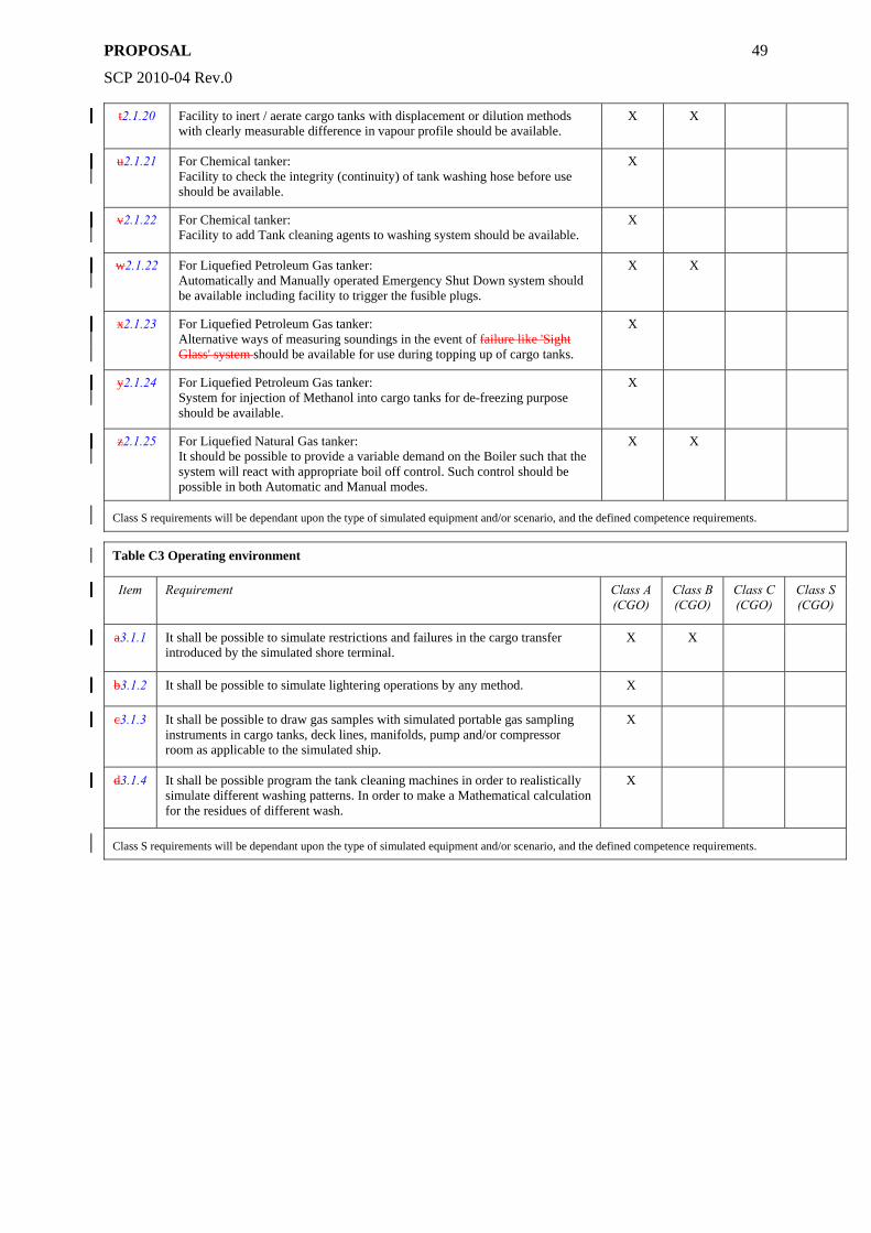
PROPOSAL
SCP 2010-04 Rev.0
49
t2.1.20 Facility to inert / aerate cargo tanks with displacement or dilution methods with clearly measurable difference in vapour profile should be available.
X X
u2.1.21 For Chemical tanker: Facility to check the integrity (continuity) of tank washing hose before use should be available.
X
v2.1.22 For Chemical tanker: Facility to add Tank cleaning agents to washing system should be available.
X
w2.1.22 For Liquefied Petroleum Gas tanker: Automatically and Manually operated Emergency Shut Down system should be available including facility to trigger the fusible plugs.
X X
x2.1.23 For Liquefied Petroleum Gas tanker: Alternative ways of measuring soundings in the event of failure like 'Sight Glass' system should be available for use during topping up of cargo tanks.
X
y2.1.24 For Liquefied Petroleum Gas tanker: System for injection of Methanol into cargo tanks for de-freezing purpose should be available.
X
z2.1.25 For Liquefied Natural Gas tanker: It should be possible to provide a variable demand on the Boiler such that the system will react with appropriate boil off control. Such control should be possible in both Automatic and Manual modes.
X X
Class S requirements will be dependant upon the type of simulated equipment and/or scenario, and the defined competence requirements.
Table C3 Operating environment
Item Requirement Class A (CGO)
Class B (CGO)
Class C (CGO)
Class S (CGO)
a3.1.1 It shall be possible to simulate restrictions and failures in the cargo transfer introduced by the simulated shore terminal.
X X
b3.1.2 It shall be possible to simulate lightering operations by any method. X
c3.1.3 It shall be possible to draw gas samples with simulated portable gas sampling instruments in cargo tanks, deck lines, manifolds, pump and/or compressor room as applicable to the simulated ship.
X
d3.1.4 It shall be possible program the tank cleaning machines in order to realistically simulate different washing patterns. In order to make a Mathematical calculation for the residues of different wash.
X
Class S requirements will be dependant upon the type of simulated equipment and/or scenario, and the defined competence requirements.
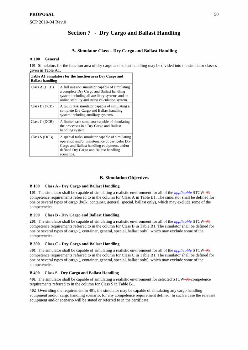
PROPOSAL
SCP 2010-04 Rev.0
50
Section 7 - Dry Cargo and Ballast Handling
A. Simulator Class – Dry Cargo and Ballast Handling
A 100 General 101 Simulators for the function area of dry cargo and ballast handling may be divided into the simulator classes given in Table A1. Table A1 Simulators for the function area Dry Cargo and Ballast handling
Class A (DCB) A full mission simulator capable of simulating a complete Dry Cargo and Ballast handling system including all auxiliary systems and an online stability and stress calculation system.
Class B (DCB) A multi task simulator capable of simulating a complete Dry Cargo and Ballast handling system including auxiliary systems.
Class C (DCB) A limited task simulator capable of simulating the processes in a Dry Cargo and Ballast handling system.
Class S (DCB) A special tasks simulator capable of simulating operation and/or maintenance of particular Dry Cargo and Ballast handling equipment, and/or defined Dry Cargo and Ballast handling scenarios.
B. Simulation Objectives
B 100 Class A - Dry Cargo and Ballast Handling 101 The simulator shall be capable of simulating a realistic environment for all of the applicable STCW-95 competence requirements referred to in the column for Class A in Table B1. The simulator shall be defined for one or several types of cargo (bulk, container, general, special, ballast only), which may exclude some of the competencies.
B 200 Class B - Dry Cargo and Ballast Handling 201 The simulator shall be capable of simulating a realistic environment for all of the applicable STCW-95 competence requirements referred to in the column for Class B in Table B1. The simulator shall be defined for one or several types of cargo (, container, general, special, ballast only), which may exclude some of the competencies.
B 300 Class C - Dry Cargo and Ballast Handling 301 The simulator shall be capable of simulating a realistic environment for all of the applicable STCW-95 competence requirements referred to in the column for Class C in Table B1. The simulator shall be defined for one or several types of cargo (, container, general, special, ballast only), which may exclude some of the competencies.
B 400 Class S - Dry Cargo and Ballast Handling 401 The simulator shall be capable of simulating a realistic environment for selected STCW-95 competence requirements referred to in the column for Class S in Table B1. 402 Overriding the requirement in 401, the simulator may be capable of simulating any cargo handling equipment and/or cargo handling scenario, for any competence requirement defined. In such a case the relevant equipment and/or scenario will be stated or referred to in the certificate.
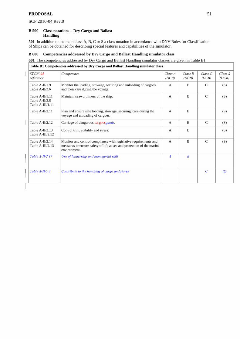
PROPOSAL
SCP 2010-04 Rev.0
51
B 500 Class notations – Dry Cargo and Ballast Handling
501 In addition to the main class A, B, C or S a class notation in accordance with DNV Rules for Classification of Ships can be obtained for describing special features and capabilities of the simulator.
B 600 Competencies addressed by Dry Cargo and Ballast Handling simulator class 601 The competencies addressed by Dry Cargo and Ballast Handling simulator classes are given in Table B1. Table B1 Competencies addressed by Dry Cargo and Ballast Handling simulator class
STCW-95 reference
Competence Class A (DCB)
Class B (DCB)
Class C (DCB)
Class S (DCB)
Table A-II/1.9 Table A-II/3.6
Monitor the loading, stowage, securing and unloading of cargoes and their care during the voyage.
A B C (S)
Table A-II/1.11 Table A-II/3.8 Table A-III/1.11
Maintain seaworthiness of the ship. A B C (S)
Table A-II/2.11 Plan and ensure safe loading, stowage, securing, care during the voyage and unloading of cargoes.
A B (S)
Table A-II/2.12 Carriage of dangerous cargoesgoods. A B C (S)
Table A-II/2.13 Table A-III/2.12
Control trim, stability and stress. A B (S)
Table A-II/2.14 Table A-III/2.13
Monitor and control compliance with legislative requirements and measures to ensure safety of life at sea and protection of the marine environment.
A B C (S)
Table A-II/2.17
Use of leadership and managerial skill A B
Table A-II/5.3
Contribute to the handling of cargo and stores C (S)
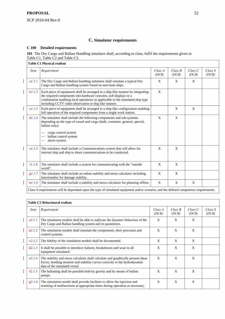
PROPOSAL
SCP 2010-04 Rev.0
52
C. Simulator requirements
C 100 Detailed requirements 101 The Dry Cargo and Ballast Handling simulator shall, according to class, fulfil the requirements given in Table C1, Table C2 and Table C3. Table C1 Physical realism
Item Requirement Class A (DCB)
Class B (DCB)
Class C (DCB)
Class S (DCB)
a1.1.1 The Dry Cargo and Ballast handling simulator shall simulate a typical Dry Cargo and Ballast handling system found on merchant ships.
X X X
b1.1.2 Each piece of equipment shall be arranged in a ship-like manner by integrating the required components into hardware consoles, soft displays or a combination enabling local operations as applicable to the simulated ship type including CCTV video observation in ship like manner.
X
c1.1.3 Each piece of equipment shall be arranged in a ship-like configuration enabling full operation of the required components from a single work station.
X X
d1.1.4 The simulator shall include the following components and sub-systems depending on the type of vessel and cargo (bulk, container, general, special, ballast only):
— cargo control system — ballast control system — alarm system.
X X
e1.1.5 The simulator shall include a Communications system that will allow for internal ship and ship to shore communications to be conducted.
X X
f1.1.6 The simulator shall include a system for communicating with the “outside world”.
X X
g1.1.7 The simulator shall include an online stability and stress calculator including functionality for damage stability.
X X
h1.1.8 The simulator shall include a stability and stress calculator for planning offline. X X X
Class S requirements will be dependant upon the type of simulated equipment and/or scenario, and the defined competence requirements.
Table C2 Behavioural realism
Item Requirement Class A (DCB)
Class B (DCB)
Class C (DCB)
Class S (DCB)
a2.1.1 The simulation models shall be able to replicate the dynamic behaviour of the Dry Cargo and Ballast handling system and its parameters.
X X X
b2.1.2 The simulation models shall simulate the components, their processes and control systems.
X X X
c2.1.2 The fidelity of the simulation models shall be documented. X X X
d2.1.3 It shall be possible to introduce failures, breakdowns and wear to all equipment simulated.
X X X
e2.1.4 The stability and stress calculator shall calculate and graphically present shear forces, bending moment and stability curves correctly to the hydrodynamic data of the simulated vessel.
X X X
f2.1.5 The ballasting shall be possible both by gravity and by means of ballast pumps.
X X X
g2.1.6 The simulation model shall provide facilities to allow the injection and resetting of malfunctions at appropriate times during operation as necessary.
X X X
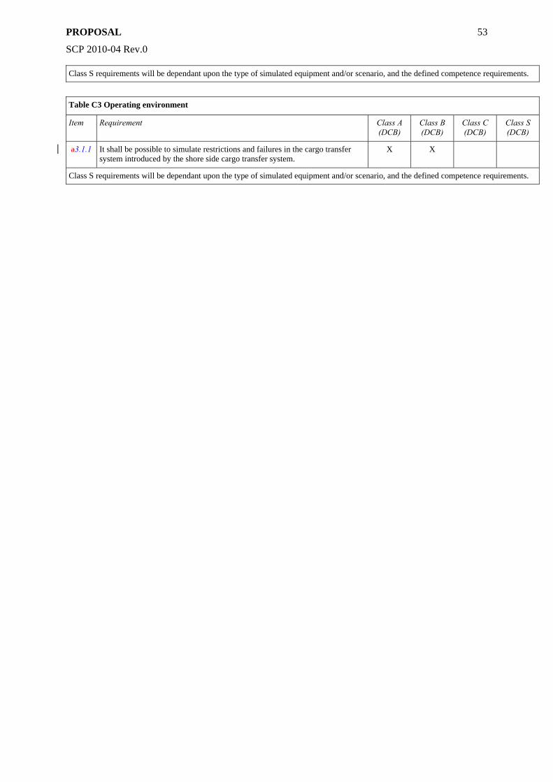
PROPOSAL
SCP 2010-04 Rev.0
53
Class S requirements will be dependant upon the type of simulated equipment and/or scenario, and the defined competence requirements.
Table C3 Operating environment
Item Requirement Class A (DCB)
Class B (DCB)
Class C (DCB)
Class S (DCB)
a3.1.1 It shall be possible to simulate restrictions and failures in the cargo transfer system introduced by the shore side cargo transfer system.
X X
Class S requirements will be dependant upon the type of simulated equipment and/or scenario, and the defined competence requirements.
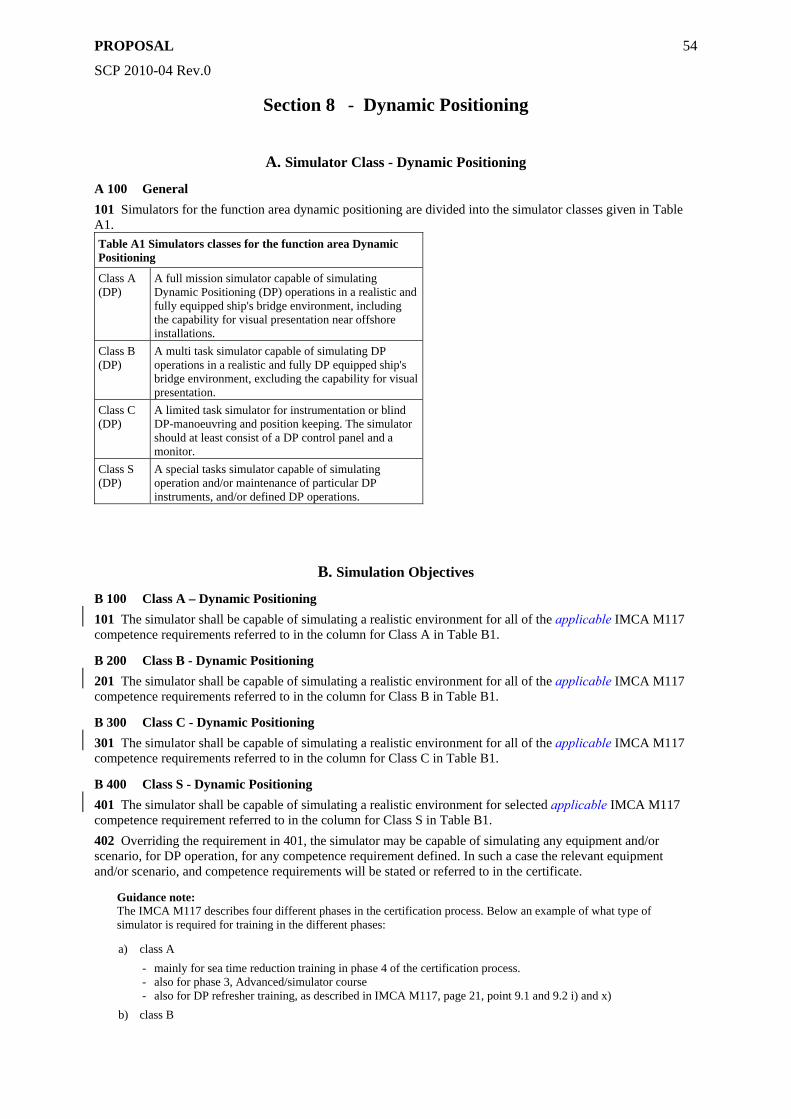
PROPOSAL
SCP 2010-04 Rev.0
54
Section 8 - Dynamic Positioning
A. Simulator Class - Dynamic Positioning
A 100 General 101 Simulators for the function area dynamic positioning are divided into the simulator classes given in Table A1. Table A1 Simulators classes for the function area Dynamic Positioning
Class A (DP)
A full mission simulator capable of simulating Dynamic Positioning (DP) operations in a realistic and fully equipped ship's bridge environment, including the capability for visual presentation near offshore installations.
Class B (DP)
A multi task simulator capable of simulating DP operations in a realistic and fully DP equipped ship's bridge environment, excluding the capability for visual presentation.
Class C (DP)
A limited task simulator for instrumentation or blind DP-manoeuvring and position keeping. The simulator should at least consist of a DP control panel and a monitor.
Class S (DP)
A special tasks simulator capable of simulating operation and/or maintenance of particular DP instruments, and/or defined DP operations.
B. Simulation Objectives
B 100 Class A – Dynamic Positioning 101 The simulator shall be capable of simulating a realistic environment for all of the applicable IMCA M117 competence requirements referred to in the column for Class A in Table B1.
B 200 Class B - Dynamic Positioning 201 The simulator shall be capable of simulating a realistic environment for all of the applicable IMCA M117 competence requirements referred to in the column for Class B in Table B1.
B 300 Class C - Dynamic Positioning 301 The simulator shall be capable of simulating a realistic environment for all of the applicable IMCA M117 competence requirements referred to in the column for Class C in Table B1.
B 400 Class S - Dynamic Positioning 401 The simulator shall be capable of simulating a realistic environment for selected applicable IMCA M117 competence requirement referred to in the column for Class S in Table B1. 402 Overriding the requirement in 401, the simulator may be capable of simulating any equipment and/or scenario, for DP operation, for any competence requirement defined. In such a case the relevant equipment and/or scenario, and competence requirements will be stated or referred to in the certificate.
Guidance note: The IMCA M117 describes four different phases in the certification process. Below an example of what type of simulator is required for training in the different phases:
a) class A - mainly for sea time reduction training in phase 4 of the certification process. - also for phase 3, Advanced/simulator course - also for DP refresher training, as described in IMCA M117, page 21, point 9.1 and 9.2 i) and x)
b) class B
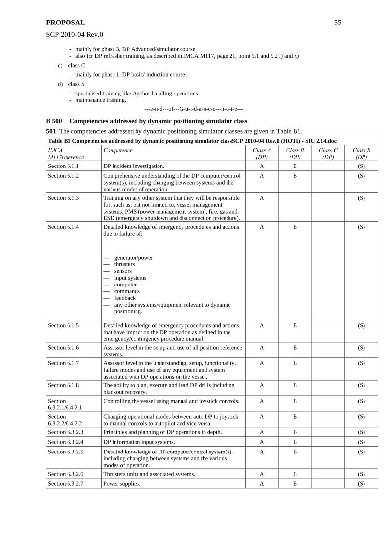
PROPOSAL
SCP 2010-04 Rev.0
55
- mainly for phase 3, DP Advanced/simulator course - also for DP refresher training, as described in IMCA M117, page 21, point 9.1 and 9.2 i) and x)
c) class C - mainly for phase 1, DP basic/ induction course
d) class S - specialised training like Anchor handling operations. - maintenance training.
---e-n-d---of---G-u-i-d-a-n-c-e---n-o-t-e---
B 500 Competencies addressed by dynamic positioning simulator class 501 The competencies addressed by dynamic positioning simulator classes are given in Table B1. Table B1 Competencies addressed by dynamic positioning simulator classSCP 2010-04 Rev.0 (HOTI) - SfC 2.14.doc
IMCA M117reference
Competence Class A (DP)
Class B (DP)
Class C (DP)
Class S (DP)
Section 6.1.1 DP incident investigation. A B (S)
Section 6.1.2 Comprehensive understanding of the DP computer/control system(s), including changing between systems and the various modes of operation.
A B (S)
Section 6.1.3 Training on any other system that they will be responsible for, such as, but not limited to, vessel management systems, PMS (power management system), fire, gas and ESD (emergency shutdown and disconnection procedure).
A (S)
Section 6.1.4 Detailed knowledge of emergency procedures and actions due to failure of:
—
— generator/power — thrusters — sensors — input systems — computer — commands — feedback — any other systems/equipment relevant to dynamic
positioning.
A B (S)
Section 6.1.5 Detailed knowledge of emergency procedures and actions that have impact on the DP operation as defined in the emergency/contingency procedure manual.
A B (S)
Section 6.1.6 Assessor level in the setup and use of all position reference systems.
A B (S)
Section 6.1.7 Assessor level in the understanding, setup, functionality, failure modes and use of any equipment and system associated with DP operations on the vessel.
A B (S)
Section 6.1.8 The ability to plan, execute and lead DP drills including blackout recovery.
A B (S)
Section 6.3.2.1/6.4.2.1
Controlling the vessel using manual and joystick controls. A B (S)
Section 6.3.2.2/6.4.2.2
Changing operational modes between auto DP to joystick to manual controls to autopilot and vice versa.
A B (S)
Section 6.3.2.3 Principles and planning of DP operations in depth. A B (S)
Section 6.3.2.4 DP information input systems. A B (S)
Section 6.3.2.5 Detailed knowledge of DP computer/control system(s), including changing between systems and the various modes of operation.
A B (S)
Section 6.3.2.6 Thrusters units and associated systems. A B (S)
Section 6.3.2.7 Power supplies. A B (S)
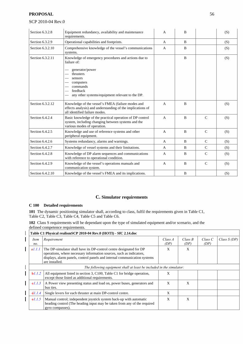
PROPOSAL
SCP 2010-04 Rev.0
56
Section 6.3.2.8 Equipment redundancy, availability and maintenance requirements.
A B (S)
Section 6.3.2.9 Operational capabilities and footprints. A B (S)
Section 6.3.2.10 Comprehensive knowledge of the vessel’s communications systems.
A B (S)
Section 6.3.2.11 Knowledge of emergency procedures and actions due to failure of:
— generator/power — thrusters — sensors — computers — commands — feedback — any other systems/equipment relevant to the DP.
B (S)
Section 6.3.2.12 Knowledge of the vessel’s FMEA (failure modes and effects analysis) and understanding of the implications of all identified failure modes.
A B (S)
Section 6.4.2.4 Basic knowledge of the practical operation of DP control system, including changing between systems and the various modes of operation.
A B C (S)
Section 6.4.2.5 Knowledge and use of reference systems and other peripheral equipment.
A B C (S)
Section 6.4.2.6 Systems redundancy, alarms and warnings. A B C (S)
Section 6.4.2.7 Knowledge of vessel systems and their limitations. A B C (S)
Section 6.4.2.8 Knowledge of DP alarm sequences and communications with reference to operational condition.
A B C (S)
Section 6.4.2.9 Knowledge of the vessel’s operations manuals and communication system.
A B C (S)
Section 6.4.2.10 Knowledge of the vessel’s FMEA and its implications. B (S)
C. Simulator requirements
C 100 Detailed requirements 101 The dynamic positioning simulator shall, according to class, fulfil the requirements given in Table C1, Table C2, Table C3, Table C4, Table C5 and Table C6. 102 Class S requirements will be dependant upon the type of simulated equipment and/or scenario, and the defined competence requirements. Table C1 Physical realismSCP 2010-04 Rev.0 (HOTI) - SfC 2.14.doc
Item no.
Requirement Class A (DP)
Class B (DP)
Class C (DP)
Class S (DP)
a1.1.1 The DP-simulator shall have its DP-control centre designated for DP operations, where necessary information sources, such as indicators, displays, alarm panels, control panels and internal communication systems are installed.
X X
The following equipment shall at least be included in the simulator:
b1.1.2 All equipment listed in section 3, C100, Table C1 for bridge operation, except those listed as additional requirements.
X
c1.1.3 A Power view presenting status and load on, power buses, generators and bus ties.
X X
d1.1.4 Single levers for each thruster at main DP-control centre. X
e1.1.5 Manual control; independent joystick system back-up with automatic heading control (The heading input may be taken from any of the required gyro compasses).
X X
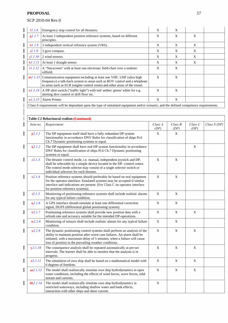
PROPOSAL
SCP 2010-04 Rev.0
57
f1.1.6 Emergency stop control for all thrusters. X X
g1.1.7 At least 3 independent position reference systems, based on different principles.
X X X
h1.1.8 3 independent vertical reference system (VRS). X X X
i1.1.9 3 gyro compass. X X X
j1.1.10 2 wind sensors. X X X
k1.1.11 At least 1 draught sensor. X X X
l1.1.12 A “Navscreen” with at least one electronic field-chart over a realistic oilfield.
X X
m1.1.13 Communication equipment including at least one VHF, UHF (ultra high frequency) a talk-back system to areas such as ROV control and a telephone to areas such as ECR (engine control room) and other areas of the vessel.
X X
n1.1.14 A DP alert switch (“traffic light”) with red/ amber/ green/ white for e.g. alerting dive control or drill floor etc.
X X
o1.1.15 Alarm Printer. X X
Class S requirements will be dependant upon the type of simulated equipment and/or scenario, and the defined competence requirements.
Table C2 Behavioural realism (Continued)
Item no. Requirement Class A (DP)
Class B (DP)
Class C (DP)
Class S (DP)
p2.1.1 The DP equipment itself shall have a fully redundant DP system functionality in accordance DNV Rules for classification of ships Pt.6 Ch.7 Dynamic positioning systems or equal.
X X
q2.1.2 The DP equipment shall have real DP system functionality in accordance DNV Rules for classification of ships Pt.6 Ch.7 Dynamic positioning systems or equal.
X
r2.1.3 The thruster control mode, i.e. manual, independent joystick and DP, shall be selectable by a simple device located in the DP- control centre. The control mode selector may consist of a single selector switch or individual selectors for each thruster.
X X
s2.1.4 Position reference systems should preferably be based on real equipment for the operator interface. Emulated systems may be accepted if similar interface and indications are present. (For Class C no operator interface for position reference systems).
X X
t2.1.5 Monitoring of positioning reference systems shall include realistic alarms for any typical failure condition.
X X
u2.1.6 A GPS interface should simulate at least one differential correction signal, DGPS (differential global positioning system).
X X
v2.1.7 Positioning reference systems shall provide new position data with a refresh rate and accuracy suitable for the intended DP-operations.
X X X
w2.1.8 Monitoring of sensors shall include realistic alarms for any typical failure condition.
X X
x2.1.9 The dynamic positioning control systems shall perform an analysis of the ability to maintain position after worst case failures. An alarm shall be initiated, with a maximum delay of 5 minutes, when a failure will cause loss of position in the prevailing weather conditions.
X X X
y2.1.10 The consequence analysis shall be repeated automatically at pre-set intervals. The learner shall be able to monitor that the analysis is in progress.
X X X
z2.1.11 The simulation of own ship shall be based on a mathematical model with 6 degrees of freedom.
X X X
aa2.1.12 The model shall realistically simulate own ship hydrodynamics in open water conditions, including the effects of wind forces, wave forces, tidal stream and currents.
X X X
bb2.1.14 The model shall realistically simulate own ship hydrodynamics in restricted waterways, including shallow water and bank effects, interaction with other ships and sheer current.
X
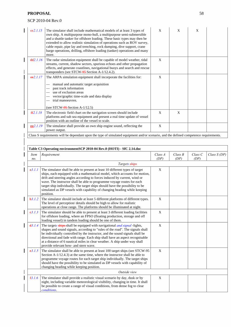
PROPOSAL
SCP 2010-04 Rev.0
58
cc2.1.15 The simulator shall include mathematical models of at least 3 types of own ship. A multipurpose mono-hull, a multipurpose semi-submersible and a shuttle tanker for offshore loading. These basic types may then be extended to allow realistic simulation of operations such as ROV survey, cable repair, pipe lay and trenching, rock dumping, dive support, crane barge operations, drilling, offshore loading (tanker) operations and many more.
X X X
dd2.1.16 The radar simulation equipment shall be capable of model weather, tidal streams, current, shadow sectors, spurious echoes and other propagation effects, and generate coastlines, navigational buoys and search and rescue transponders (see STCW-95 Section A-1/12.4.2).
X
ee2.1.17 The ARPA simulation equipment shall incorporate the facilities for:
— manual and automatic target acquisition — past track information — use of exclusion areas — vector/graphic time-scale and data display — trial manoeuvres.
(see STCW-95 Section A-1/12.5)
X
ff2.1.18 The electronic field chart on the navigation screen should include platforms and sub sea equipment and present a real time update of vessel position with an outline of the vessel to scale.
X X
gg2.1.19 The simulator shall provide an own ship engine sound, reflecting the power output.
X
Class S requirements will be dependant upon the type of simulated equipment and/or scenario, and the defined competence requirements.
Table C3 Operating environmentSCP 2010-04 Rev.0 (HOTI) - SfC 2.14.doc
Item no.
Requirement Class A (DP)
Class B (DP)
Class C (DP)
Class S (DP)
Targets ships
a3.1.1 The simulator shall be able to present at least 10 different types of target ships, each equipped with a mathematical model, which accounts for motion, drift and steering angles according to forces induced by current, wind or wave. The instructor shall be able to programme voyage routes for each target ship individually. The target ships should have the possibility to be simulated as DP vessels with capability of changing heading while keeping position.
X
b3.1.2 The simulator should include at least 5 different platforms of different types. The level of perception/ details should be high to allow for realistic operations at close range. The platforms should be illuminated at night.
X
c3.1.3 The simulator should be able to present at least 3 different loading facilities for offshore loading, where an FPSO (floating production, storage and off loading vessel) in tandem loading should be one of them.
X
d3.1.4 The targets ships shall be equipped with navigational and signal -lights, shapes and sound signals, according to "rules of the road". The signals shall be individually controlled by the instructor, and the sound signals shall be directional and fade with range. Each ship shall have an aspect recognisable at a distance of 6 nautical miles in clear weather. A ship under way shall provide relevant bow- and stern wave.
X
e3.1.5 The simulator shall be able to present at least 100 target ships (see STCW-95 Section A-1/12.4.3) at the same time, where the instructor shall be able to programme voyage routes for each target ship individually. The target ships should have the possibility to be simulated as DP vessels with capability of changing heading while keeping position.
X
Outside view
f3.1.6 The simulator shall provide a realistic visual scenario by day, dusk or by night, including variable meteorological visibility, changing in time. It shall be possible to create a range of visual conditions, from dense fog to clear conditions.
X
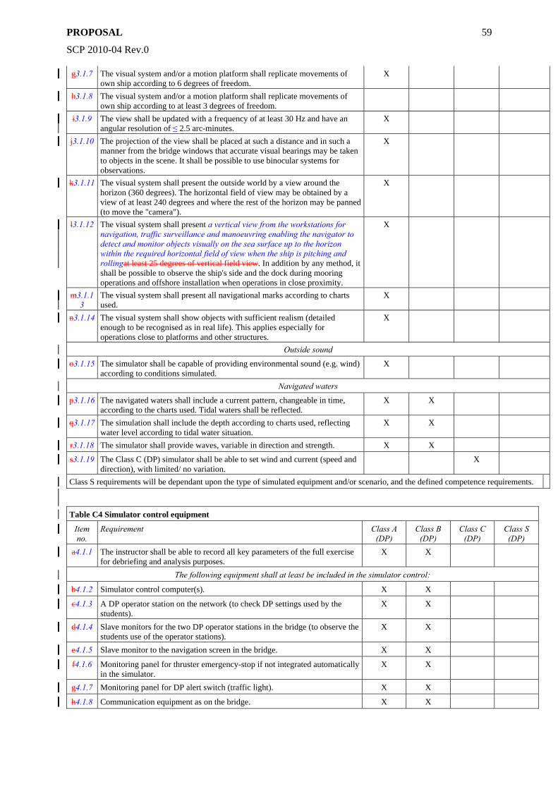
PROPOSAL
SCP 2010-04 Rev.0
59
g3.1.7 The visual system and/or a motion platform shall replicate movements of own ship according to 6 degrees of freedom.
X
h3.1.8 The visual system and/or a motion platform shall replicate movements of own ship according to at least 3 degrees of freedom.
i3.1.9 The view shall be updated with a frequency of at least 30 Hz and have an angular resolution of ≤ 2.5 arc-minutes.
X
j3.1.10 The projection of the view shall be placed at such a distance and in such a manner from the bridge windows that accurate visual bearings may be taken to objects in the scene. It shall be possible to use binocular systems for observations.
X
k3.1.11 The visual system shall present the outside world by a view around the horizon (360 degrees). The horizontal field of view may be obtained by a view of at least 240 degrees and where the rest of the horizon may be panned (to move the "camera").
X
l3.1.12 The visual system shall present a vertical view from the workstations for navigation, traffic surveillance and manoeuvring enabling the navigator to detect and monitor objects visually on the sea surface up to the horizon within the required horizontal field of view when the ship is pitching and rollingat least 25 degrees of vertical field view. In addition by any method, it shall be possible to observe the ship's side and the dock during mooring operations and offshore installation when operations in close proximity.
X
m3.1.13
The visual system shall present all navigational marks according to charts used.
X
n3.1.14 The visual system shall show objects with sufficient realism (detailed enough to be recognised as in real life). This applies especially for operations close to platforms and other structures.
X
Outside sound
o3.1.15 The simulator shall be capable of providing environmental sound (e.g. wind) according to conditions simulated.
X
Navigated waters
p3.1.16 The navigated waters shall include a current pattern, changeable in time, according to the charts used. Tidal waters shall be reflected.
X X
q3.1.17 The simulation shall include the depth according to charts used, reflecting water level according to tidal water situation.
X X
r3.1.18 The simulator shall provide waves, variable in direction and strength. X X
s3.1.19 The Class C (DP) simulator shall be able to set wind and current (speed and direction), with limited/ no variation.
X
Class S requirements will be dependant upon the type of simulated equipment and/or scenario, and the defined competence requirements.
Table C4 Simulator control equipment
Item no.
Requirement Class A (DP)
Class B (DP)
Class C (DP)
Class S (DP)
a4.1.1 The instructor shall be able to record all key parameters of the full exercise for debriefing and analysis purposes.
X X
The following equipment shall at least be included in the simulator control:
b4.1.2 Simulator control computer(s). X X
c4.1.3 A DP operator station on the network (to check DP settings used by the students).
X X
d4.1.4 Slave monitors for the two DP operator stations in the bridge (to observe the students use of the operator stations).
X X
e4.1.5 Slave monitor to the navigation screen in the bridge. X X
f4.1.6 Monitoring panel for thruster emergency-stop if not integrated automatically in the simulator.
X X
g4.1.7 Monitoring panel for DP alert switch (traffic light). X X
h4.1.8 Communication equipment as on the bridge. X X
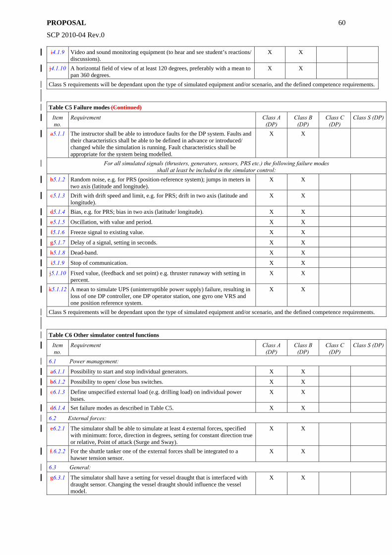
PROPOSAL
SCP 2010-04 Rev.0
60
i4.1.9 Video and sound monitoring equipment (to hear and see student’s reactions/ discussions).
X X
j4.1.10 A horizontal field of view of at least 120 degrees, preferably with a mean to pan 360 degrees.
X X
Class S requirements will be dependant upon the type of simulated equipment and/or scenario, and the defined competence requirements.
Table C5 Failure modes (Continued)
Item no.
Requirement Class A (DP)
Class B (DP)
Class C (DP)
Class S (DP)
a5.1.1 The instructor shall be able to introduce faults for the DP system. Faults and their characteristics shall be able to be defined in advance or introduced/ changed while the simulation is running. Fault characteristics shall be appropriate for the system being modelled.
X X
For all simulated signals (thrusters, generators, sensors, PRS etc.) the following failure modes shall at least be included in the simulator control:
b5.1.2 Random noise, e.g. for PRS (position-reference system); jumps in meters in two axis (latitude and longitude).
X X
c5.1.3 Drift with drift speed and limit, e.g. for PRS; drift in two axis (latitude and longitude).
X X
d5.1.4 Bias, e.g. for PRS; bias in two axis (latitude/ longitude). X X
e5.1.5 Oscillation, with value and period. X X
f5.1.6 Freeze signal to existing value. X X
g5.1.7 Delay of a signal, setting in seconds. X X
h5.1.8 Dead-band. X X
i5.1.9 Stop of communication. X X
j5.1.10 Fixed value, (feedback and set point) e.g. thruster runaway with setting in percent.
X X
k5.1.12 A mean to simulate UPS (uninterruptible power supply) failure, resulting in loss of one DP controller, one DP operator station, one gyro one VRS and one position reference system.
X X
Class S requirements will be dependant upon the type of simulated equipment and/or scenario, and the defined competence requirements.
Table C6 Other simulator control functions
Item no.
Requirement Class A (DP)
Class B (DP)
Class C (DP)
Class S (DP)
6.1 Power management:
a6.1.1 Possibility to start and stop individual generators. X X
b6.1.2 Possibility to open/ close bus switches. X X
c6.1.3 Define unspecified external load (e.g. drilling load) on individual power buses.
X X
d6.1.4 Set failure modes as described in Table C5. X X
6.2 External forces:
e6.2.1 The simulator shall be able to simulate at least 4 external forces, specified with minimum: force, direction in degrees, setting for constant direction true or relative, Point of attack (Surge and Sway).
X X
f.6.2.2 For the shuttle tanker one of the external forces shall be integrated to a hawser tension sensor.
X X
6.3 General:
g6.3.1 The simulator shall have a setting for vessel draught that is interfaced with draught sensor. Changing the vessel draught should influence the vessel model.
X X
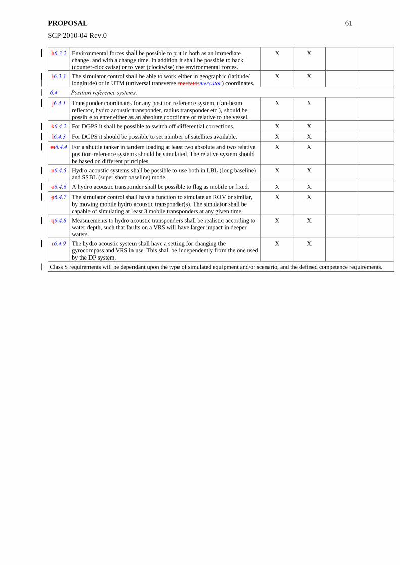
PROPOSAL
SCP 2010-04 Rev.0
61
h6.3.2 Environmental forces shall be possible to put in both as an immediate change, and with a change time. In addition it shall be possible to back (counter-clockwise) or to veer (clockwise) the environmental forces.
X X
i6.3.3 The simulator control shall be able to work either in geographic (latitude/ longitude) or in UTM (universal transverse mercatormercator) coordinates.
X X
6.4 Position reference systems:
j6.4.1 Transponder coordinates for any position reference system, (fan-beam reflector, hydro acoustic transponder, radius transponder etc.), should be possible to enter either as an absolute coordinate or relative to the vessel.
X X
k6.4.2 For DGPS it shall be possible to switch off differential corrections. X X
l6.4.3 For DGPS it should be possible to set number of satellites available. X X
m6.4.4 For a shuttle tanker in tandem loading at least two absolute and two relative position-reference systems should be simulated. The relative system should be based on different principles.
X X
n6.4.5 Hydro acoustic systems shall be possible to use both in LBL (long baseline) and SSBL (super short baseline) mode.
X X
o6.4.6 A hydro acoustic transponder shall be possible to flag as mobile or fixed. X X
p6.4.7 The simulator control shall have a function to simulate an ROV or similar, by moving mobile hydro acoustic transponder(s). The simulator shall be capable of simulating at least 3 mobile transponders at any given time.
X X
q6.4.8 Measurements to hydro acoustic transponders shall be realistic according to water depth, such that faults on a VRS will have larger impact in deeper waters.
X X
r6.4.9 The hydro acoustic system shall have a setting for changing the gyrocompass and VRS in use. This shall be independently from the one used by the DP system.
X X
Class S requirements will be dependant upon the type of simulated equipment and/or scenario, and the defined competence requirements.
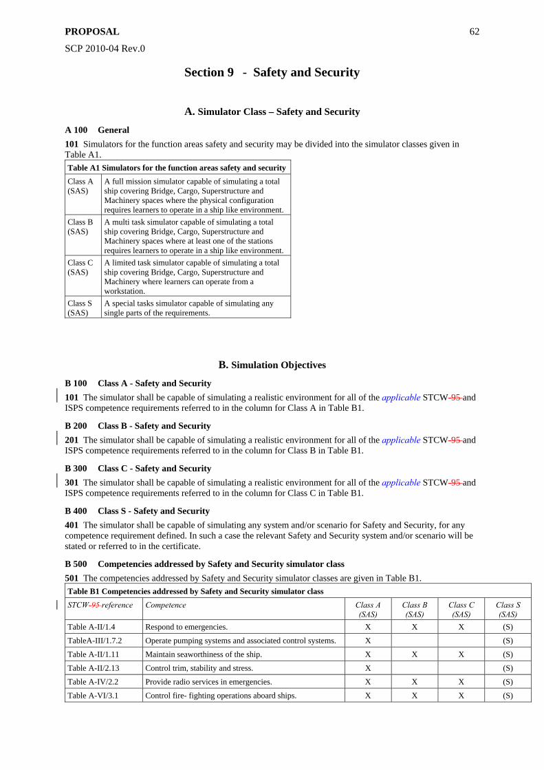
PROPOSAL
SCP 2010-04 Rev.0
62
Section 9 - Safety and Security
A. Simulator Class – Safety and Security
A 100 General 101 Simulators for the function areas safety and security may be divided into the simulator classes given in Table A1. Table A1 Simulators for the function areas safety and security
Class A (SAS)
A full mission simulator capable of simulating a total ship covering Bridge, Cargo, Superstructure and Machinery spaces where the physical configuration requires learners to operate in a ship like environment.
Class B (SAS)
A multi task simulator capable of simulating a total ship covering Bridge, Cargo, Superstructure and Machinery spaces where at least one of the stations requires learners to operate in a ship like environment.
Class C (SAS)
A limited task simulator capable of simulating a total ship covering Bridge, Cargo, Superstructure and Machinery where learners can operate from a workstation.
Class S (SAS)
A special tasks simulator capable of simulating any single parts of the requirements.
B. Simulation Objectives
B 100 Class A - Safety and Security 101 The simulator shall be capable of simulating a realistic environment for all of the applicable STCW-95 and ISPS competence requirements referred to in the column for Class A in Table B1.
B 200 Class B - Safety and Security 201 The simulator shall be capable of simulating a realistic environment for all of the applicable STCW-95 and ISPS competence requirements referred to in the column for Class B in Table B1.
B 300 Class C - Safety and Security 301 The simulator shall be capable of simulating a realistic environment for all of the applicable STCW-95 and ISPS competence requirements referred to in the column for Class C in Table B1.
B 400 Class S - Safety and Security 401 The simulator shall be capable of simulating any system and/or scenario for Safety and Security, for any competence requirement defined. In such a case the relevant Safety and Security system and/or scenario will be stated or referred to in the certificate.
B 500 Competencies addressed by Safety and Security simulator class 501 The competencies addressed by Safety and Security simulator classes are given in Table B1. Table B1 Competencies addressed by Safety and Security simulator class
STCW-95 reference Competence Class A (SAS)
Class B (SAS)
Class C (SAS)
Class S (SAS)
Table A-II/1.4 Respond to emergencies. X X X (S)
TableA-III/1.7.2 Operate pumping systems and associated control systems. X (S)
Table A-II/1.11 Maintain seaworthiness of the ship. X X X (S)
Table A-II/2.13 Control trim, stability and stress. X (S)
Table A-IV/2.2 Provide radio services in emergencies. X X X (S)
Table A-VI/3.1 Control fire- fighting operations aboard ships. X X X (S)
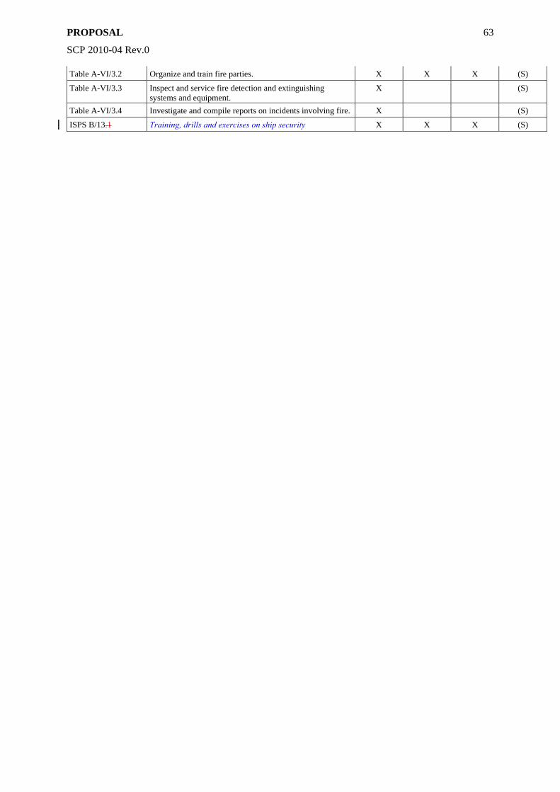
PROPOSAL
SCP 2010-04 Rev.0
63
Table A-VI/3.2 Organize and train fire parties. X X X (S)
Table A-VI/3.3 Inspect and service fire detection and extinguishing systems and equipment.
X (S)
Table A-VI/3.4 Investigate and compile reports on incidents involving fire. X (S)
ISPS B/13.1 Training, drills and exercises on ship security X X X (S)
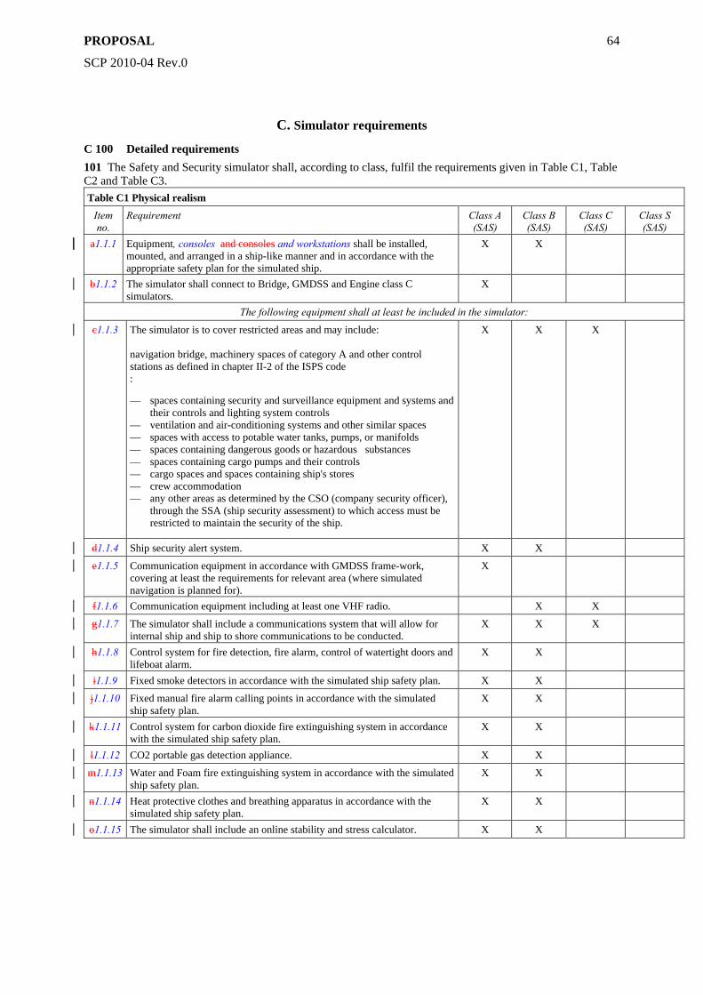
PROPOSAL
SCP 2010-04 Rev.0
64
C. Simulator requirements
C 100 Detailed requirements 101 The Safety and Security simulator shall, according to class, fulfil the requirements given in Table C1, Table C2 and Table C3.
Table C1 Physical realism
Item no.
Requirement Class A (SAS)
Class B (SAS)
Class C (SAS)
Class S (SAS)
a1.1.1 Equipment, consoles and consoles and workstations shall be installed, mounted, and arranged in a ship-like manner and in accordance with the appropriate safety plan for the simulated ship.
X X
b1.1.2 The simulator shall connect to Bridge, GMDSS and Engine class C simulators.
X
The following equipment shall at least be included in the simulator:
c1.1.3 The simulator is to cover restricted areas and may include: navigation bridge, machinery spaces of category A and other control stations as defined in chapter II-2 of the ISPS code :
— spaces containing security and surveillance equipment and systems and their controls and lighting system controls
— ventilation and air-conditioning systems and other similar spaces — spaces with access to potable water tanks, pumps, or manifolds — spaces containing dangerous goods or hazardous substances — spaces containing cargo pumps and their controls — cargo spaces and spaces containing ship's stores — crew accommodation — any other areas as determined by the CSO (company security officer),
through the SSA (ship security assessment) to which access must be restricted to maintain the security of the ship.
X X X
d1.1.4 Ship security alert system. X X
e1.1.5 Communication equipment in accordance with GMDSS frame-work, covering at least the requirements for relevant area (where simulated navigation is planned for).
X
f1.1.6 Communication equipment including at least one VHF radio. X X
g1.1.7 The simulator shall include a communications system that will allow for internal ship and ship to shore communications to be conducted.
X X X
h1.1.8 Control system for fire detection, fire alarm, control of watertight doors and lifeboat alarm.
X X
i1.1.9 Fixed smoke detectors in accordance with the simulated ship safety plan. X X
j1.1.10 Fixed manual fire alarm calling points in accordance with the simulated ship safety plan.
X X
k1.1.11 Control system for carbon dioxide fire extinguishing system in accordance with the simulated ship safety plan.
X X
l1.1.12 CO2 portable gas detection appliance. X X
m1.1.13 Water and Foam fire extinguishing system in accordance with the simulated ship safety plan.
X X
n1.1.14 Heat protective clothes and breathing apparatus in accordance with the simulated ship safety plan.
X X
o1.1.15 The simulator shall include an online stability and stress calculator. X X
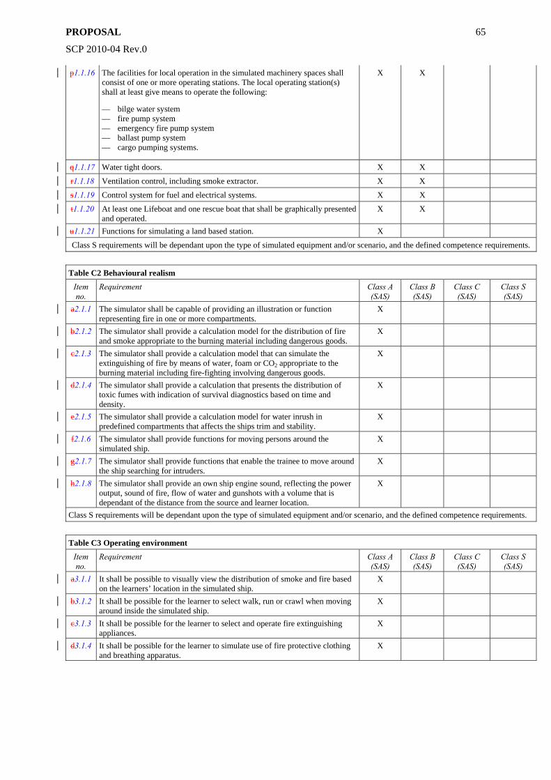
PROPOSAL
SCP 2010-04 Rev.0
65
p1.1.16 The facilities for local operation in the simulated machinery spaces shall consist of one or more operating stations. The local operating station(s) shall at least give means to operate the following:
— bilge water system — fire pump system — emergency fire pump system — ballast pump system — cargo pumping systems.
X X
q1.1.17 Water tight doors. X X
r1.1.18 Ventilation control, including smoke extractor. X X
s1.1.19 Control system for fuel and electrical systems. X X
t1.1.20 At least one Lifeboat and one rescue boat that shall be graphically presented and operated.
X X
u1.1.21 Functions for simulating a land based station. X
Class S requirements will be dependant upon the type of simulated equipment and/or scenario, and the defined competence requirements.
Table C2 Behavioural realism
Item no.
Requirement Class A (SAS)
Class B (SAS)
Class C (SAS)
Class S (SAS)
a2.1.1 The simulator shall be capable of providing an illustration or function representing fire in one or more compartments.
X
b2.1.2 The simulator shall provide a calculation model for the distribution of fire and smoke appropriate to the burning material including dangerous goods.
X
c2.1.3 The simulator shall provide a calculation model that can simulate the extinguishing of fire by means of water, foam or CO2 appropriate to the burning material including fire-fighting involving dangerous goods.
X
d2.1.4 The simulator shall provide a calculation that presents the distribution of toxic fumes with indication of survival diagnostics based on time and density.
X
e2.1.5 The simulator shall provide a calculation model for water inrush in predefined compartments that affects the ships trim and stability.
X
f2.1.6 The simulator shall provide functions for moving persons around the simulated ship.
X
g2.1.7 The simulator shall provide functions that enable the trainee to move around the ship searching for intruders.
X
h2.1.8 The simulator shall provide an own ship engine sound, reflecting the power output, sound of fire, flow of water and gunshots with a volume that is dependant of the distance from the source and learner location.
X
Class S requirements will be dependant upon the type of simulated equipment and/or scenario, and the defined competence requirements.
Table C3 Operating environment
Item no.
Requirement Class A (SAS)
Class B (SAS)
Class C (SAS)
Class S (SAS)
a3.1.1 It shall be possible to visually view the distribution of smoke and fire based on the learners’ location in the simulated ship.
X
b3.1.2 It shall be possible for the learner to select walk, run or crawl when moving around inside the simulated ship.
X
c3.1.3 It shall be possible for the learner to select and operate fire extinguishing appliances.
X
d3.1.4 It shall be possible for the learner to simulate use of fire protective clothing and breathing apparatus.
X
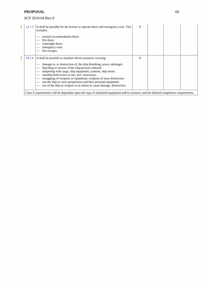
PROPOSAL
SCP 2010-04 Rev.0
66
e3.1.5 It shall be possible for the learner to operate doors and emergency exits. This includes:
— normal accommodation doors — fire doors — watertight doors — emergency exits — fire escapes.
X
f3.1.6 It shall be possible to simulate threat scenarios covering:
— damage to, or destruction of, the ship (bombing, arson, sabotage) — hijacking or seizure of the ship/persons onboard — tampering with cargo, ship equipment, systems, ship stores — unauthorized access or use, incl. stowaways — smuggling of weapons or equipment, weapons of mass destruction — use the ship to carry perpetrators and their personal equipment — use of the ship as weapon or as means to cause damage, destruction.
X
Class S requirements will be dependant upon the type of simulated equipment and/or scenario, and the defined competence requirements.
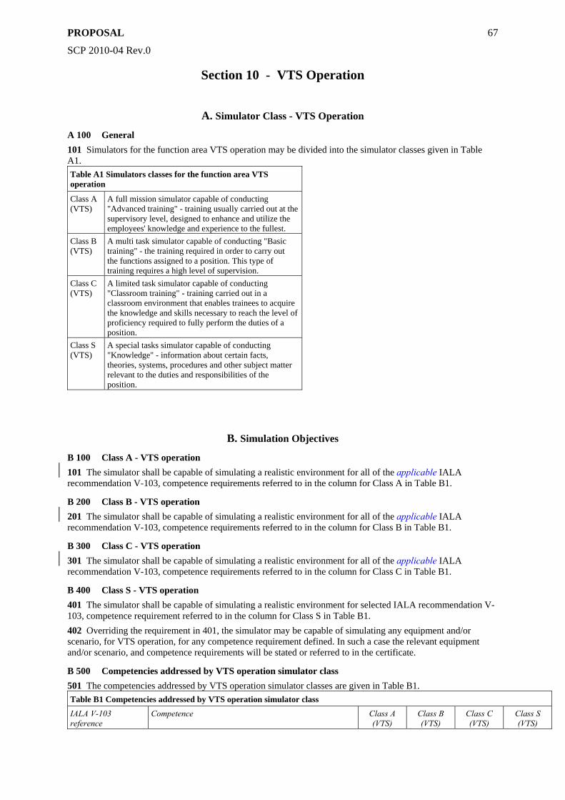
PROPOSAL
SCP 2010-04 Rev.0
67
Section 10 - VTS Operation
A. Simulator Class - VTS Operation
A 100 General 101 Simulators for the function area VTS operation may be divided into the simulator classes given in Table A1. Table A1 Simulators classes for the function area VTS operation
Class A (VTS)
A full mission simulator capable of conducting "Advanced training" - training usually carried out at the supervisory level, designed to enhance and utilize the employees' knowledge and experience to the fullest.
Class B (VTS)
A multi task simulator capable of conducting "Basic training" - the training required in order to carry out the functions assigned to a position. This type of training requires a high level of supervision.
Class C (VTS)
A limited task simulator capable of conducting "Classroom training" - training carried out in a classroom environment that enables trainees to acquire the knowledge and skills necessary to reach the level of proficiency required to fully perform the duties of a position.
Class S (VTS)
A special tasks simulator capable of conducting "Knowledge" - information about certain facts, theories, systems, procedures and other subject matter relevant to the duties and responsibilities of the position.
B. Simulation Objectives
B 100 Class A - VTS operation 101 The simulator shall be capable of simulating a realistic environment for all of the applicable IALA recommendation V-103, competence requirements referred to in the column for Class A in Table B1.
B 200 Class B - VTS operation 201 The simulator shall be capable of simulating a realistic environment for all of the applicable IALA recommendation V-103, competence requirements referred to in the column for Class B in Table B1.
B 300 Class C - VTS operation 301 The simulator shall be capable of simulating a realistic environment for all of the applicable IALA recommendation V-103, competence requirements referred to in the column for Class C in Table B1.
B 400 Class S - VTS operation 401 The simulator shall be capable of simulating a realistic environment for selected IALA recommendation V-103, competence requirement referred to in the column for Class S in Table B1. 402 Overriding the requirement in 401, the simulator may be capable of simulating any equipment and/or scenario, for VTS operation, for any competence requirement defined. In such a case the relevant equipment and/or scenario, and competence requirements will be stated or referred to in the certificate.
B 500 Competencies addressed by VTS operation simulator class 501 The competencies addressed by VTS operation simulator classes are given in Table B1. Table B1 Competencies addressed by VTS operation simulator class
IALA V-103 reference
Competence Class A (VTS)
Class B (VTS)
Class C (VTS)
Class S (VTS)
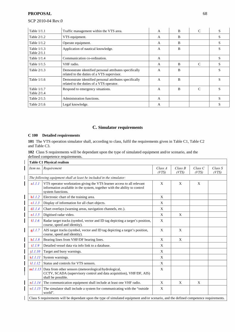
PROPOSAL
SCP 2010-04 Rev.0
68
Table 1/1.1 Traffic management within the VTS area. A B C S
Table 2/1.2 VTS equipment. A B S
Table 1/1.2 Operate equipment. A B S
Table 1/1.3 Table 2/1.1
Application of nautical knowledge. A B S
Table 1/1.4 Communication co-ordination. A S
Table 1/1.5 VHF radio. A B C S
Table 2/1.3 Demonstrate identified personal attributes specifically related to the duties of a VTS supervisor.
A B S
Table 1/1.6 Demonstrate identified personal attributes specifically related to the duties of a VTS operator.
A B S
Table 1/1.7 Table 2/1.4
Respond to emergency situations. A B C S
Table 2/1.5 Administration functions. A S
Table 2/1.6 Legal knowledge. A S
C. Simulator requirements
C 100 Detailed requirements 101 The VTS operation simulator shall, according to class, fulfil the requirements given in Table C1, Table C2 and Table C3. 102 Class S requirements will be dependant upon the type of simulated equipment and/or scenario, and the defined competence requirements. Table C1 Physical realism
Item no. Requirement Class A (VTS)
Class B (VTS)
Class C (VTS)
Class S (VTS)
The following equipment shall at least be included in the simulator:
a1.1.1 VTS operator workstation giving the VTS learner access to all relevant information available in the system, together with the ability to control system functions.
X X X
b1.1.2 Electronic chart of the training area. X
c1.1.3 Display of information for all chart objects. X
d1.1.4 Chart overlays (warning areas, navigation channels, etc.). X
e1.1.5 Digitised radar video. X X
f1.1.6 Radar target tracks (symbol, vector and ID tag depicting a target’s position, course, speed and identity).
X
g1.1.7 AIS target tracks (symbol, vector and ID tag depicting a target’s position, course, speed and identity).
X X
h1.1.8 Bearing lines from VHF/DF bearing lines. X X
i1.1.9 Detailed vessel data via info link to a database. X
j1.1.10 Target and buoy warnings. X
k1.1.11 System warnings. X
l1.1.12 Status and controls for VTS sensors. X
m1.1.13 Data from other sensors (meteorological/hydrological, CCTV, SCADA (supervisory control and data acquisition), VHF/DF, AIS) shall be possible.
X
n1.1.14 The communication equipment shall include at least one VHF radio. X X X
o1.1.15 The simulator shall include a system for communicating with the “outside world”.
X
Class S requirements will be dependant upon the type of simulated equipment and/or scenario, and the defined competence requirements.
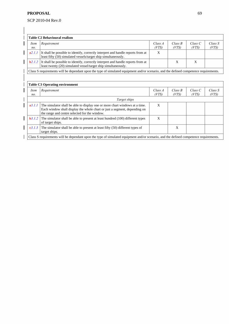
PROPOSAL
SCP 2010-04 Rev.0
69
Table C2 Behavioural realism
Item no.
Requirement Class A (VTS)
Class B (VTS)
Class C (VTS)
Class S (VTS)
a2.1.1 It shall be possible to identify, correctly interpret and handle reports from at least fifty (50) simulated vessels/target ship simultaneously.
X
b2.1.2 It shall be possible to identify, correctly interpret and handle reports from at least twenty (20) simulated vessel/target ship simultaneously.
X X
Class S requirements will be dependant upon the type of simulated equipment and/or scenario, and the defined competence requirements.
Table C3 Operating environment
Item no.
Requirement Class A (VTS)
Class B (VTS)
Class C (VTS)
Class S (VTS)
Target ships
a3.1.1 The simulator shall be able to display one or more chart windows at a time. Each window shall display the whole chart or just a segment, depending on the range and centre selected for the window.
X
b3.1.2 The simulator shall be able to present at least hundred (100) different types of target ships.
X
c3.1.3 The simulator shall be able to present at least fifty (50) different types of target ships.
X
Class S requirements will be dependant upon the type of simulated equipment and/or scenario, and the defined competence requirements.

PROPOSAL
SCP 2010-04 Rev.0
70
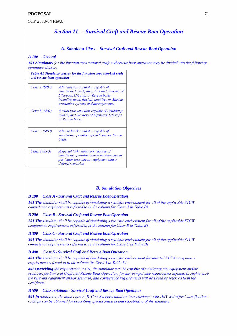
PROPOSAL
SCP 2010-04 Rev.0
71
Section 11 - Survival Craft and Rescue Boat Operation
A. Simulator Class – Survival Craft and Rescue Boat Operation
A 100 General 101 Simulators for the function area survival craft and rescue boat operation may be divided into the following simulator classes:
Table A1 Simulator classes for the function area survival craft and rescue boat operation
Class A (SRO) A full mission simulator capable of simulating launch, operation and recovery of Lifeboats, Life rafts or Rescue boats including davit, freefall, float free or Marine evacuation systems and arrangements.
Class B (SRO) A multi task simulator capable of simulating launch, and recovery of Lifeboats, Life rafts or Rescue boats.
Class C (SRO) A limited task simulator capable of simulating operation of Lifeboats, or Rescue boats.
Class S (SRO) A special tasks simulator capable of simulating operation and/or maintenance of particular instruments, equipment and/or defined scenarios.
B. Simulation Objectives
B 100 Class A - Survival Craft and Rescue Boat Operation 101 The simulator shall be capable of simulating a realistic environment for all of the applicable STCW competence requirements referred to in the column for Class A in Table B1.
B 200 Class B - Survival Craft and Rescue Boat Operation 201 The simulator shall be capable of simulating a realistic environment for all of the applicable STCW competence requirements referred to in the column for Class B in Table B1.
B 300 Class C - Survival Craft and Rescue Boat Operation 301 The simulator shall be capable of simulating a realistic environment for all of the applicable STCW competence requirements referred to in the column for Class C in Table B1.
B 400 Class S - Survival Craft and Rescue Boat Operation 401 The simulator shall be capable of simulating a realistic environment for selected STCW competence requirement referred to in the column for Class S in Table B1. 402 Overriding the requirement in 401, the simulator may be capable of simulating any equipment and/or scenario, for Survival Craft and Rescue Boat Operation, for any competence requirement defined. In such a case the relevant equipment and/or scenario, and competence requirements will be stated or referred to in the certificate.
B 500 Class notations - Survival Craft and Rescue Boat Operation 501 In addition to the main class A, B, C or S a class notation in accordance with DNV Rules for Classification of Ships can be obtained for describing special features and capabilities of the simulator.
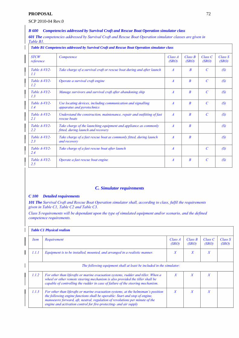
PROPOSAL
SCP 2010-04 Rev.0
72
B 600 Competencies addressed by Survival Craft and Rescue Boat Operation simulator class 601 The competencies addressed by Survival Craft and Rescue Boat Operation simulator classes are given in Table B1.
Table B1 Competencies addressed by Survival Craft and Rescue Boat Operation simulator class
STCW reference
Competence Class A (SRO)
Class B (SRO)
Class C (SRO)
Class S (SRO)
Table A-VI/2-1.1
Take charge of a survival craft or rescue boat during and after launch A B C (S)
Table A-VI/2-1.2
Operate a survival craft engine A B C (S)
Table A-VI/2-1.3
Manage survivors and survival craft after abandoning ship A B C (S)
Table A-VI/2-1.4
Use locating devices, including communication and signalling apparatus and pyrotechnics
A B C (S)
Table A-VI/2-2.1
Understand the construction, maintenance, repair and outfitting of fast rescue boats
A B C (S)
Table A-VI/2-2.2
Take charge of the launching equipment and appliance as commonly fitted, during launch and recovery
A B (S)
Table A-VI/2-2.3
Take charge of a fast rescue boat as commonly fitted, during launch and recovery
A B (S)
Table A-VI/2-2.4
Take charge of a fast rescue boat after launch A C (S)
Table A-VI/2-2.5
Operate a fast rescue boat engine A B C (S)
C. Simulator requirements
C 100 Detailed requirements 101 The Survival Craft and Rescue Boat Operation simulator shall, according to class, fulfil the requirements given in Table C1, Table C2 and Table C3. Class S requirements will be dependant upon the type of simulated equipment and/or scenario, and the defined competence requirements.
Table C1 Physical realism
Item Requirement Class A (SRO)
Class B (SRO)
Class C (SRO)
Class S (SRO)
1.1.1 Equipment is to be installed, mounted, and arranged in a realistic manner. X X X
The following equipment shall at least be included in the simulator:
1.1.2 For other than liferafts or marine evacuation systems, rudder and tiller. When a wheel or other remote steering mechanism is also provided the tiller shall be capable of controlling the rudder in case of failure of the steering mechanism.
X X X
1.1.3 For other than liferafts or marine evacuation systems, at the helmsman’s position the following engine functions shall be operable: Start and stop of engine, manoeuvre forward, aft, neutral, regulation of revolutions per minute of the engine and activation control for fire-protecting- and air supply
X X X
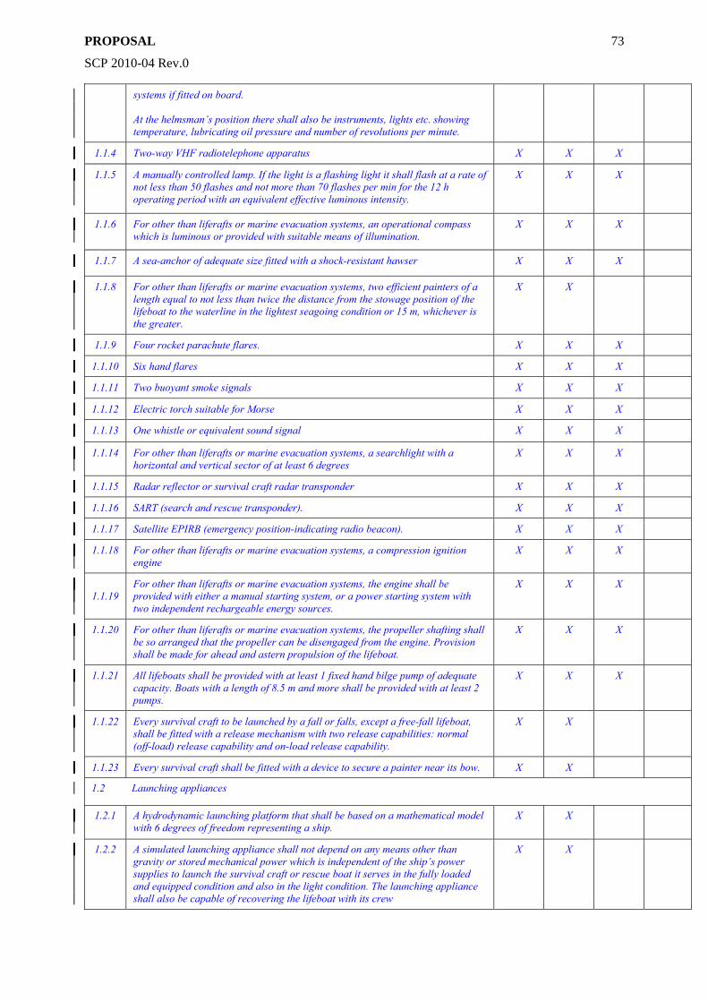
PROPOSAL
SCP 2010-04 Rev.0
73
systems if fitted on board. At the helmsman’s position there shall also be instruments, lights etc. showing temperature, lubricating oil pressure and number of revolutions per minute.
1.1.4 Two-way VHF radiotelephone apparatus X X X
1.1.5 A manually controlled lamp. If the light is a flashing light it shall flash at a rate of not less than 50 flashes and not more than 70 flashes per min for the 12 h operating period with an equivalent effective luminous intensity.
X X X
1.1.6 For other than liferafts or marine evacuation systems, an operational compass which is luminous or provided with suitable means of illumination.
X X X
1.1.7 A sea-anchor of adequate size fitted with a shock-resistant hawser X X X
1.1.8 For other than liferafts or marine evacuation systems, two efficient painters of a length equal to not less than twice the distance from the stowage position of the lifeboat to the waterline in the lightest seagoing condition or 15 m, whichever is the greater.
X X
1.1.9 Four rocket parachute flares. X X X
1.1.10 Six hand flares X X X
1.1.11 Two buoyant smoke signals X X X
1.1.12 Electric torch suitable for Morse X X X
1.1.13 One whistle or equivalent sound signal X X X
1.1.14 For other than liferafts or marine evacuation systems, a searchlight with a horizontal and vertical sector of at least 6 degrees
X X X
1.1.15 Radar reflector or survival craft radar transponder X X X
1.1.16 SART (search and rescue transponder). X X X
1.1.17 Satellite EPIRB (emergency position-indicating radio beacon). X X X
1.1.18 For other than liferafts or marine evacuation systems, a compression ignition engine
X X X
1.1.19
For other than liferafts or marine evacuation systems, the engine shall be provided with either a manual starting system, or a power starting system with two independent rechargeable energy sources.
X X X
1.1.20 For other than liferafts or marine evacuation systems, the propeller shafting shall be so arranged that the propeller can be disengaged from the engine. Provision shall be made for ahead and astern propulsion of the lifeboat.
X X X
1.1.21 All lifeboats shall be provided with at least 1 fixed hand bilge pump of adequate capacity. Boats with a length of 8.5 m and more shall be provided with at least 2 pumps.
X X X
1.1.22 Every survival craft to be launched by a fall or falls, except a free-fall lifeboat, shall be fitted with a release mechanism with two release capabilities: normal (off-load) release capability and on-load release capability.
X X
1.1.23 Every survival craft shall be fitted with a device to secure a painter near its bow. X X
1.2 Launching appliances
1.2.1 A hydrodynamic launching platform that shall be based on a mathematical model with 6 degrees of freedom representing a ship.
X X
1.2.2 A simulated launching appliance shall not depend on any means other than gravity or stored mechanical power which is independent of the ship’s power supplies to launch the survival craft or rescue boat it serves in the fully loaded and equipped condition and also in the light condition. The launching appliance shall also be capable of recovering the lifeboat with its crew
X X
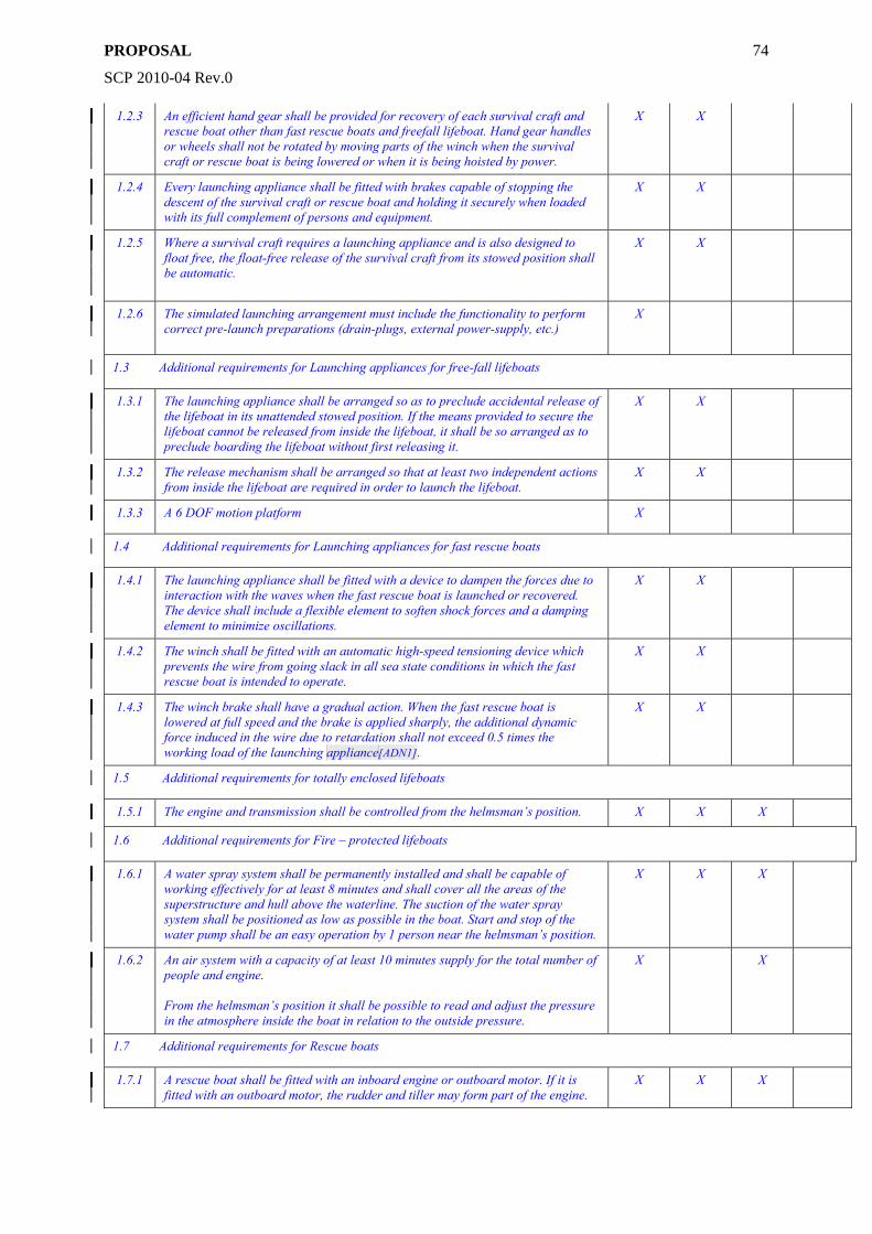
PROPOSAL
SCP 2010-04 Rev.0
74
1.2.3 An efficient hand gear shall be provided for recovery of each survival craft and rescue boat other than fast rescue boats and freefall lifeboat. Hand gear handles or wheels shall not be rotated by moving parts of the winch when the survival craft or rescue boat is being lowered or when it is being hoisted by power.
X X
1.2.4 Every launching appliance shall be fitted with brakes capable of stopping the descent of the survival craft or rescue boat and holding it securely when loaded with its full complement of persons and equipment.
X X
1.2.5 Where a survival craft requires a launching appliance and is also designed to float free, the float-free release of the survival craft from its stowed position shall be automatic.
X X
1.2.6 The simulated launching arrangement must include the functionality to perform correct pre-launch preparations (drain-plugs, external power-supply, etc.)
X
1.3 Additional requirements for Launching appliances for free-fall lifeboats
1.3.1 The launching appliance shall be arranged so as to preclude accidental release of the lifeboat in its unattended stowed position. If the means provided to secure the lifeboat cannot be released from inside the lifeboat, it shall be so arranged as to preclude boarding the lifeboat without first releasing it.
X X
1.3.2 The release mechanism shall be arranged so that at least two independent actions from inside the lifeboat are required in order to launch the lifeboat.
X X
1.3.3 A 6 DOF motion platform X
1.4 Additional requirements for Launching appliances for fast rescue boats
1.4.1 The launching appliance shall be fitted with a device to dampen the forces due to interaction with the waves when the fast rescue boat is launched or recovered. The device shall include a flexible element to soften shock forces and a damping element to minimize oscillations.
X X
1.4.2 The winch shall be fitted with an automatic high-speed tensioning device which prevents the wire from going slack in all sea state conditions in which the fast rescue boat is intended to operate.
X X
1.4.3 The winch brake shall have a gradual action. When the fast rescue boat is lowered at full speed and the brake is applied sharply, the additional dynamic force induced in the wire due to retardation shall not exceed 0.5 times the working load of the launching appliance[ADN1].
X X
1.5 Additional requirements for totally enclosed lifeboats
1.5.1 The engine and transmission shall be controlled from the helmsman’s position. X X X
1.6 Additional requirements for Fire – protected lifeboats
1.6.1 A water spray system shall be permanently installed and shall be capable of working effectively for at least 8 minutes and shall cover all the areas of the superstructure and hull above the waterline. The suction of the water spray system shall be positioned as low as possible in the boat. Start and stop of the water pump shall be an easy operation by 1 person near the helmsman’s position.
X X X
1.6.2 An air system with a capacity of at least 10 minutes supply for the total number of people and engine. From the helmsman’s position it shall be possible to read and adjust the pressure in the atmosphere inside the boat in relation to the outside pressure.
X X
1.7 Additional requirements for Rescue boats
1.7.1 A rescue boat shall be fitted with an inboard engine or outboard motor. If it is fitted with an outboard motor, the rudder and tiller may form part of the engine.
X X X
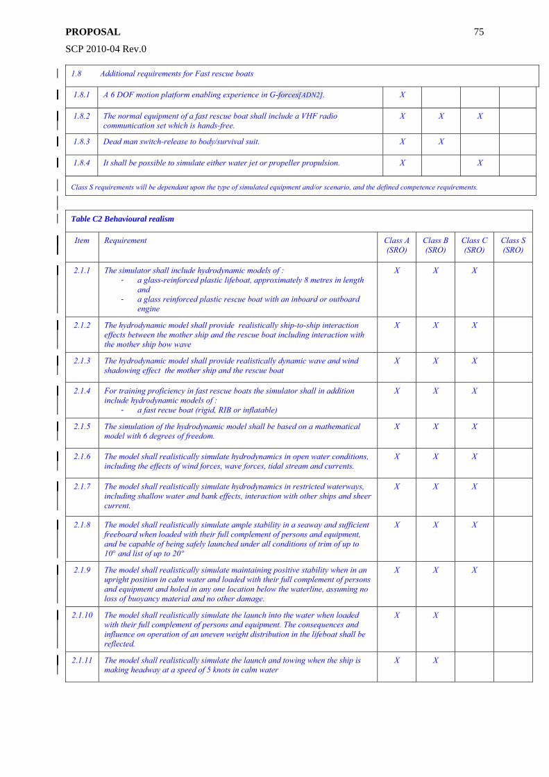
PROPOSAL
SCP 2010-04 Rev.0
75
1.8 Additional requirements for Fast rescue boats
1.8.1 A 6 DOF motion platform enabling experience in G-forces[ADN2]. X
1.8.2 The normal equipment of a fast rescue boat shall include a VHF radio communication set which is hands-free.
X X X
1.8.3 Dead man switch-release to body/survival suit. X X
1.8.4 It shall be possible to simulate either water jet or propeller propulsion. X X
Class S requirements will be dependant upon the type of simulated equipment and/or scenario, and the defined competence requirements.
Table C2 Behavioural realism
Item Requirement Class A (SRO)
Class B (SRO)
Class C (SRO)
Class S (SRO)
2.1.1 The simulator shall include hydrodynamic models of : - a glass-reinforced plastic lifeboat, approximately 8 metres in length
and - a glass reinforced plastic rescue boat with an inboard or outboard
engine
X X X
2.1.2 The hydrodynamic model shall provide realistically ship-to-ship interaction effects between the mother ship and the rescue boat including interaction with the mother ship bow wave
X X X
2.1.3 The hydrodynamic model shall provide realistically dynamic wave and wind shadowing effect the mother ship and the rescue boat
X X X
2.1.4 For training proficiency in fast rescue boats the simulator shall in addition include hydrodynamic models of :
- a fast recue boat (rigid, RIB or inflatable)
X X X
2.1.5 The simulation of the hydrodynamic model shall be based on a mathematical model with 6 degrees of freedom.
X X X
2.1.6 The model shall realistically simulate hydrodynamics in open water conditions, including the effects of wind forces, wave forces, tidal stream and currents.
X X X
2.1.7 The model shall realistically simulate hydrodynamics in restricted waterways, including shallow water and bank effects, interaction with other ships and sheer current.
X X X
2.1.8 The model shall realistically simulate ample stability in a seaway and sufficient freeboard when loaded with their full complement of persons and equipment, and be capable of being safely launched under all conditions of trim of up to 10° and list of up to 20º
X X X
2.1.9 The model shall realistically simulate maintaining positive stability when in an upright position in calm water and loaded with their full complement of persons and equipment and holed in any one location below the waterline, assuming no loss of buoyancy material and no other damage.
X X X
2.1.10 The model shall realistically simulate the launch into the water when loaded with their full complement of persons and equipment. The consequences and influence on operation of an uneven weight distribution in the lifeboat shall be reflected.
X X
2.1.11 The model shall realistically simulate the launch and towing when the ship is making headway at a speed of 5 knots in calm water
X X
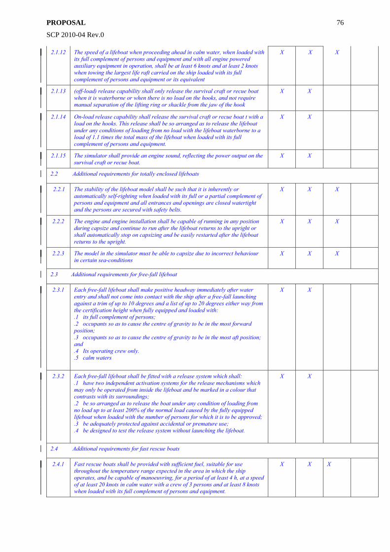
PROPOSAL
SCP 2010-04 Rev.0
76
2.1.12 The speed of a lifeboat when proceeding ahead in calm water, when loaded with its full complement of persons and equipment and with all engine powered auxiliary equipment in operation, shall be at least 6 knots and at least 2 knots when towing the largest life raft carried on the ship loaded with its full complement of persons and equipment or its equivalent
X X X
2.1.13 (off-load) release capability shall only release the survival craft or recue boat when it is waterborne or when there is no load on the hooks, and not require manual separation of the lifting ring or shackle from the jaw of the hook
X X
2.1.14 On-load release capability shall release the survival craft or recue boat t with a load on the hooks. This release shall be so arranged as to release the lifeboat under any conditions of loading from no load with the lifeboat waterborne to a load of 1.1 times the total mass of the lifeboat when loaded with its full complement of persons and equipment.
X X
2.1.15 The simulator shall provide an engine sound, reflecting the power output on the survival craft or recue boat.
X X
2.2 Additional requirements for totally enclosed lifeboats
2.2.1 The stability of the lifeboat model shall be such that it is inherently or automatically self-righting when loaded with its full or a partial complement of persons and equipment and all entrances and openings are closed watertight and the persons are secured with safety belts.
X X X
2.2.2 The engine and engine installation shall be capable of running in any position during capsize and continue to run after the lifeboat returns to the upright or shall automatically stop on capsizing and be easily restarted after the lifeboat returns to the upright.
X X X
2.2.3 The model in the simulator must be able to capsize due to incorrect behaviour in certain sea-conditions
X X X
2.3 Additional requirements for free-fall lifeboat
2.3.1 Each free-fall lifeboat shall make positive headway immediately after water entry and shall not come into contact with the ship after a free-fall launching against a trim of up to 10 degrees and a list of up to 20 degrees either way from the certification height when fully equipped and loaded with: .1 its full complement of persons; .2 occupants so as to cause the centre of gravity to be in the most forward position; .3 occupants so as to cause the centre of gravity to be in the most aft position; and .4 Its operating crew only. .5 calm waters
X X
2.3.2 Each free-fall lifeboat shall be fitted with a release system which shall: .1 have two independent activation systems for the release mechanisms which may only be operated from inside the lifeboat and be marked in a colour that contrasts with its surroundings; .2 be so arranged as to release the boat under any condition of loading from no load up to at least 200% of the normal load caused by the fully equipped lifeboat when loaded with the number of persons for which it is to be approved; .3 be adequately protected against accidental or premature use; .4 be designed to test the release system without launching the lifeboat.
X X
2.4 Additional requirements for fast rescue boats
2.4.1 Fast rescue boats shall be provided with sufficient fuel, suitable for use throughout the temperature range expected in the area in which the ship operates, and be capable of manoeuvring, for a period of at least 4 h, at a speed of at least 20 knots in calm water with a crew of 3 persons and at least 8 knots when loaded with its full complement of persons and equipment.
X X X
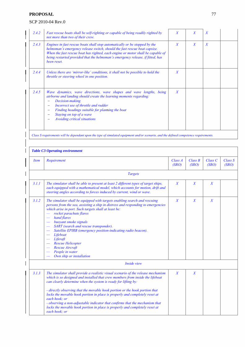
PROPOSAL
SCP 2010-04 Rev.0
77
2.4.2 Fast rescue boats shall be self-righting or capable of being readily righted by not more than two of their crew.
X X X
2.4.3 Engines in fast rescue boats shall stop automatically or be stopped by the helmsman’s emergency release switch, should the fast rescue boat capsize. When the fast rescue boat has righted, each engine or motor shall be capable of being restarted provided that the helmsman’s emergency release, if fitted, has been reset.
X X X
2.4.4 Unless there are ‘mirror-like’ conditions, it shall not be possible to hold the throttle or steering wheel in one position.
X
2.4.5 Wave dynamics, wave directions, wave shapes and wave lengths, being airborne and landing should create the learning moments regarding: − Decision-making − Incorrect use of throttle and rudder − Finding headings suitable for planning the boat − Staying on top of a wave − Avoiding critical situations
X
Class S requirements will be dependant upon the type of simulated equipment and/or scenario, and the defined competence requirements.
Table C3 Operating environment
Item Requirement Class A (SRO)
Class B (SRO)
Class C (SRO)
Class S (SRO)
Targets
3.1.1 The simulator shall be able to present at least 2 different types of target ships, each equipped with a mathematical model, which accounts for motion, drift and steering angles according to forces induced by current, wind or wave.
X X X
3.1.2 The simulator shall be equipped with targets enabling search and rescuing persons from the sea, assisting a ship in distress and responding to emergencies which arise in port. Such targets shall at least be: — rocket parachute flares — hand flares — buoyant smoke signals — SART (search and rescue transponder). — Satellite EPIRB (emergency position-indicating radio beacon). — Lifeboat — Liferaft — Rescue Helicopter — Rescue Aircraft — People in water — Own ship or installation
X X X
Inside view
3.1.3 The simulator shall provide a realistic visual scenario of the release mechanism which is so designed and installed that crew members from inside the lifeboat can clearly determine when the system is ready for lifting by: - directly observing that the movable hook portion or the hook portion that locks the movable hook portion in place is properly and completely reset at each hook; or - observing a non-adjustable indicator that confirms that the mechanism that locks the movable hook portion in place is properly and completely reset at each hook; or
X X
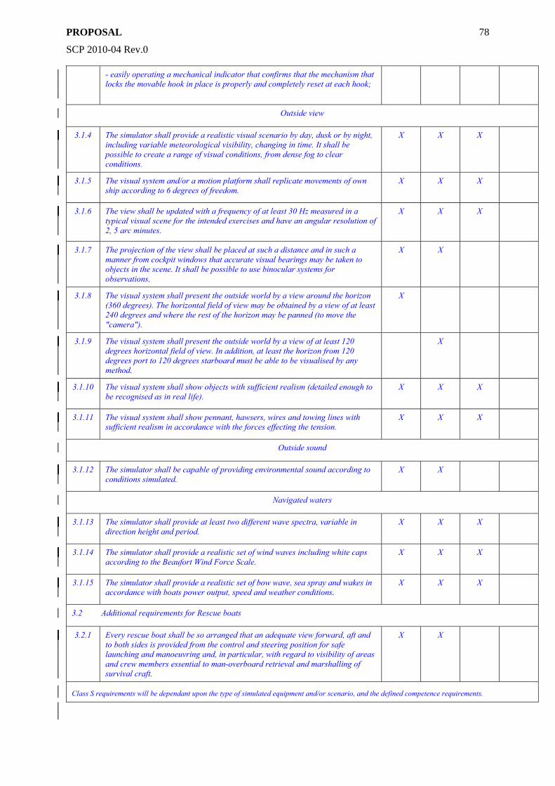
PROPOSAL
SCP 2010-04 Rev.0
78
- easily operating a mechanical indicator that confirms that the mechanism that locks the movable hook in place is properly and completely reset at each hook;
Outside view
3.1.4 The simulator shall provide a realistic visual scenario by day, dusk or by night, including variable meteorological visibility, changing in time. It shall be possible to create a range of visual conditions, from dense fog to clear conditions.
X X X
3.1.5 The visual system and/or a motion platform shall replicate movements of own ship according to 6 degrees of freedom.
X X X
3.1.6 The view shall be updated with a frequency of at least 30 Hz measured in a typical visual scene for the intended exercises and have an angular resolution of 2, 5 arc minutes.
X X X
3.1.7 The projection of the view shall be placed at such a distance and in such a manner from cockpit windows that accurate visual bearings may be taken to objects in the scene. It shall be possible to use binocular systems for observations.
X X
3.1.8 The visual system shall present the outside world by a view around the horizon (360 degrees). The horizontal field of view may be obtained by a view of at least 240 degrees and where the rest of the horizon may be panned (to move the "camera").
X
3.1.9 The visual system shall present the outside world by a view of at least 120 degrees horizontal field of view. In addition, at least the horizon from 120 degrees port to 120 degrees starboard must be able to be visualised by any method.
X
3.1.10 The visual system shall show objects with sufficient realism (detailed enough to be recognised as in real life).
X X X
3.1.11 The visual system shall show pennant, hawsers, wires and towing lines with sufficient realism in accordance with the forces effecting the tension.
X X X
Outside sound
3.1.12 The simulator shall be capable of providing environmental sound according to conditions simulated.
X X
Navigated waters
3.1.13 The simulator shall provide at least two different wave spectra, variable in direction height and period.
X X X
3.1.14 The simulator shall provide a realistic set of wind waves including white caps according to the Beaufort Wind Force Scale.
X X X
3.1.15 The simulator shall provide a realistic set of bow wave, sea spray and wakes in accordance with boats power output, speed and weather conditions.
X X X
3.2 Additional requirements for Rescue boats
3.2.1 Every rescue boat shall be so arranged that an adequate view forward, aft and to both sides is provided from the control and steering position for safe launching and manoeuvring and, in particular, with regard to visibility of areas and crew members essential to man-overboard retrieval and marshalling of survival craft.
X X
Class S requirements will be dependant upon the type of simulated equipment and/or scenario, and the defined competence requirements.
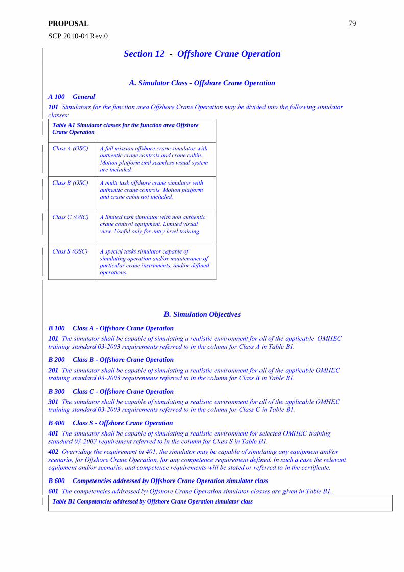
PROPOSAL
SCP 2010-04 Rev.0
79
Section 12 - Offshore Crane Operation
A. Simulator Class - Offshore Crane Operation
A 100 General 101 Simulators for the function area Offshore Crane Operation may be divided into the following simulator classes:
Table A1 Simulator classes for the function area Offshore Crane Operation
Class A (OSC) A full mission offshore crane simulator with authentic crane controls and crane cabin. Motion platform and seamless visual system are included.
Class B (OSC) A multi task offshore crane simulator with authentic crane controls. Motion platform and crane cabin not included.
Class C (OSC) A limited task simulator with non authentic crane control equipment. Limited visual view. Useful only for entry level training
Class S (OSC) A special tasks simulator capable of simulating operation and/or maintenance of particular crane instruments, and/or defined operations.
B. Simulation Objectives
B 100 Class A - Offshore Crane Operation 101 The simulator shall be capable of simulating a realistic environment for all of the applicable OMHEC training standard 03-2003 requirements referred to in the column for Class A in Table B1.
B 200 Class B - Offshore Crane Operation 201 The simulator shall be capable of simulating a realistic environment for all of the applicable OMHEC training standard 03-2003 requirements referred to in the column for Class B in Table B1.
B 300 Class C - Offshore Crane Operation 301 The simulator shall be capable of simulating a realistic environment for all of the applicable OMHEC training standard 03-2003 requirements referred to in the column for Class C in Table B1.
B 400 Class S - Offshore Crane Operation 401 The simulator shall be capable of simulating a realistic environment for selected OMHEC training standard 03-2003 requirement referred to in the column for Class S in Table B1. 402 Overriding the requirement in 401, the simulator may be capable of simulating any equipment and/or scenario, for Offshore Crane Operation, for any competence requirement defined. In such a case the relevant equipment and/or scenario, and competence requirements will be stated or referred to in the certificate.
B 600 Competencies addressed by Offshore Crane Operation simulator class 601 The competencies addressed by Offshore Crane Operation simulator classes are given in Table B1.
Table B1 Competencies addressed by Offshore Crane Operation simulator class
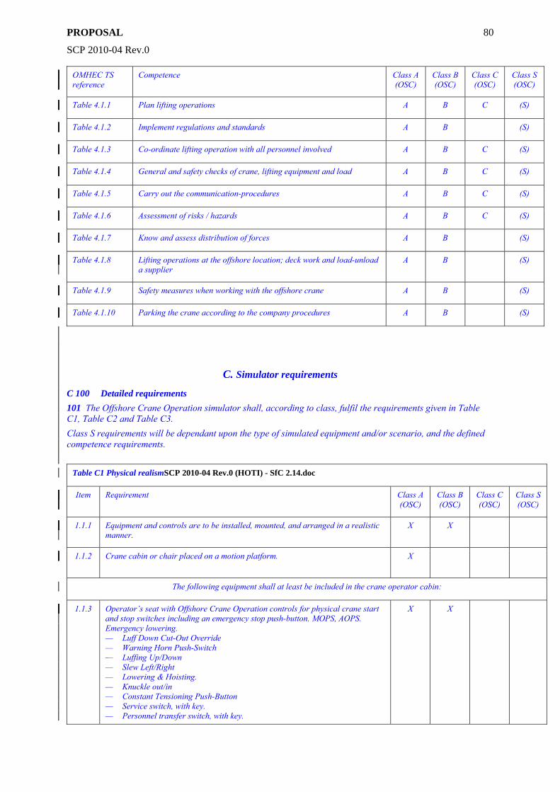
PROPOSAL
SCP 2010-04 Rev.0
80
OMHEC TS reference
Competence Class A (OSC)
Class B (OSC)
Class C (OSC)
Class S (OSC)
Table 4.1.1 Plan lifting operations A B C (S)
Table 4.1.2 Implement regulations and standards A B (S)
Table 4.1.3 Co-ordinate lifting operation with all personnel involved A B C (S)
Table 4.1.4 General and safety checks of crane, lifting equipment and load A B C (S)
Table 4.1.5 Carry out the communication-procedures A B C (S)
Table 4.1.6 Assessment of risks / hazards A B C (S)
Table 4.1.7 Know and assess distribution of forces A B (S)
Table 4.1.8 Lifting operations at the offshore location; deck work and load-unload a supplier
A B (S)
Table 4.1.9 Safety measures when working with the offshore crane A B (S)
Table 4.1.10 Parking the crane according to the company procedures A B (S)
C. Simulator requirements
C 100 Detailed requirements 101 The Offshore Crane Operation simulator shall, according to class, fulfil the requirements given in Table C1, Table C2 and Table C3. Class S requirements will be dependant upon the type of simulated equipment and/or scenario, and the defined competence requirements.
Table C1 Physical realismSCP 2010-04 Rev.0 (HOTI) - SfC 2.14.doc
Item Requirement Class A (OSC)
Class B (OSC)
Class C (OSC)
Class S (OSC)
1.1.1 Equipment and controls are to be installed, mounted, and arranged in a realistic manner.
X X
1.1.2 Crane cabin or chair placed on a motion platform. X
The following equipment shall at least be included in the crane operator cabin:
1.1.3 Operator’s seat with Offshore Crane Operation controls for physical crane start and stop switches including an emergency stop push-button. MOPS, AOPS. Emergency lowering. — Luff Down Cut-Out Override — Warning Horn Push-Switch — Luffing Up/Down — Slew Left/Right — Lowering & Hoisting. — Knuckle out/in — Constant Tensioning Push-Button — Service switch, with key. — Personnel transfer switch, with key.
X X
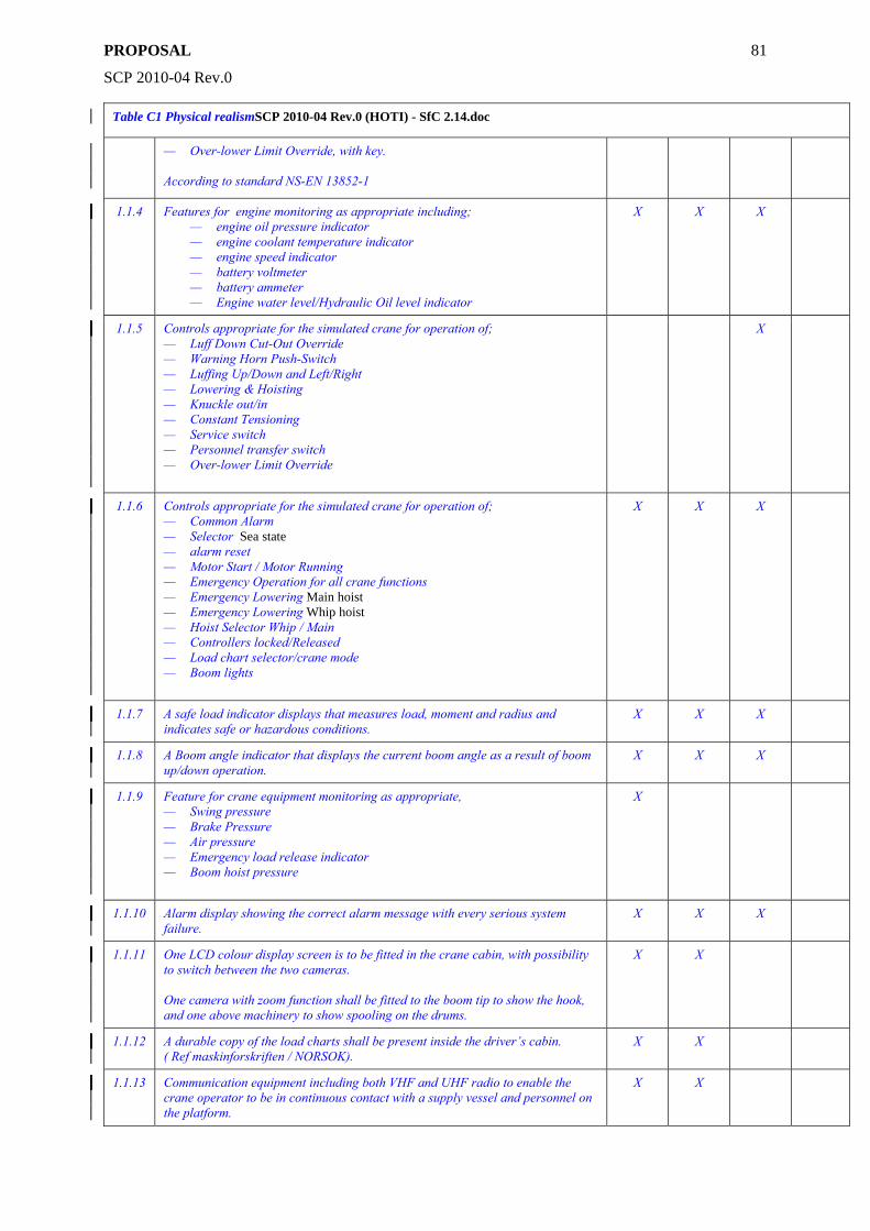
PROPOSAL
SCP 2010-04 Rev.0
81
Table C1 Physical realismSCP 2010-04 Rev.0 (HOTI) - SfC 2.14.doc
— Over-lower Limit Override, with key. According to standard NS-EN 13852-1
1.1.4 Features for engine monitoring as appropriate including; — engine oil pressure indicator — engine coolant temperature indicator — engine speed indicator — battery voltmeter — battery ammeter — Engine water level/Hydraulic Oil level indicator
X X X
1.1.5 Controls appropriate for the simulated crane for operation of; — Luff Down Cut-Out Override — Warning Horn Push-Switch — Luffing Up/Down and Left/Right — Lowering & Hoisting — Knuckle out/in — Constant Tensioning — Service switch — Personnel transfer switch — Over-lower Limit Override
X
1.1.6 Controls appropriate for the simulated crane for operation of; — Common Alarm — Selector Sea state — alarm reset — Motor Start / Motor Running — Emergency Operation for all crane functions — Emergency Lowering Main hoist — Emergency Lowering Whip hoist — Hoist Selector Whip / Main — Controllers locked/Released — Load chart selector/crane mode — Boom lights
X X X
1.1.7 A safe load indicator displays that measures load, moment and radius and indicates safe or hazardous conditions.
X X X
1.1.8 A Boom angle indicator that displays the current boom angle as a result of boom up/down operation.
X X X
1.1.9 Feature for crane equipment monitoring as appropriate, — Swing pressure — Brake Pressure — Air pressure — Emergency load release indicator — Boom hoist pressure
X
1.1.10 Alarm display showing the correct alarm message with every serious system failure.
X X X
1.1.11 One LCD colour display screen is to be fitted in the crane cabin, with possibility to switch between the two cameras. One camera with zoom function shall be fitted to the boom tip to show the hook, and one above machinery to show spooling on the drums.
X X
1.1.12 A durable copy of the load charts shall be present inside the driver’s cabin. ( Ref maskinforskriften / NORSOK).
X X
1.1.13 Communication equipment including both VHF and UHF radio to enable the crane operator to be in continuous contact with a supply vessel and personnel on the platform.
X X
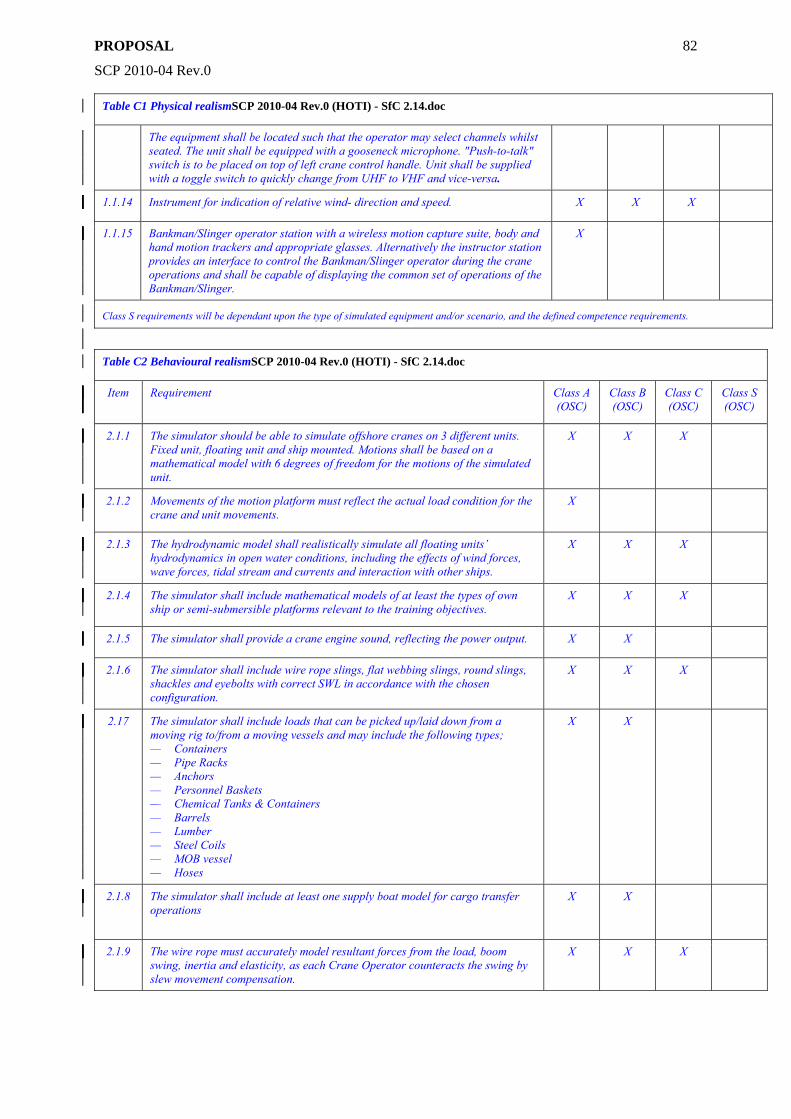
PROPOSAL
SCP 2010-04 Rev.0
82
Table C1 Physical realismSCP 2010-04 Rev.0 (HOTI) - SfC 2.14.doc
The equipment shall be located such that the operator may select channels whilst seated. The unit shall be equipped with a gooseneck microphone. "Push-to-talk" switch is to be placed on top of left crane control handle. Unit shall be supplied with a toggle switch to quickly change from UHF to VHF and vice-versa.
1.1.14 Instrument for indication of relative wind- direction and speed. X X X
1.1.15 Bankman/Slinger operator station with a wireless motion capture suite, body and hand motion trackers and appropriate glasses. Alternatively the instructor station provides an interface to control the Bankman/Slinger operator during the crane operations and shall be capable of displaying the common set of operations of the Bankman/Slinger.
X
Class S requirements will be dependant upon the type of simulated equipment and/or scenario, and the defined competence requirements.
Table C2 Behavioural realismSCP 2010-04 Rev.0 (HOTI) - SfC 2.14.doc
Item Requirement Class A (OSC)
Class B (OSC)
Class C (OSC)
Class S (OSC)
2.1.1 The simulator should be able to simulate offshore cranes on 3 different units. Fixed unit, floating unit and ship mounted. Motions shall be based on a mathematical model with 6 degrees of freedom for the motions of the simulated unit.
X X X
2.1.2 Movements of the motion platform must reflect the actual load condition for the crane and unit movements.
X
2.1.3 The hydrodynamic model shall realistically simulate all floating units’ hydrodynamics in open water conditions, including the effects of wind forces, wave forces, tidal stream and currents and interaction with other ships.
X X X
2.1.4 The simulator shall include mathematical models of at least the types of own ship or semi-submersible platforms relevant to the training objectives.
X X X
2.1.5 The simulator shall provide a crane engine sound, reflecting the power output. X X
2.1.6 The simulator shall include wire rope slings, flat webbing slings, round slings, shackles and eyebolts with correct SWL in accordance with the chosen configuration.
X X X
2.17 The simulator shall include loads that can be picked up/laid down from a moving rig to/from a moving vessels and may include the following types; — Containers — Pipe Racks — Anchors — Personnel Baskets — Chemical Tanks & Containers — Barrels — Lumber — Steel Coils — MOB vessel — Hoses
X X
2.1.8 The simulator shall include at least one supply boat model for cargo transfer operations
X X
2.1.9 The wire rope must accurately model resultant forces from the load, boom swing, inertia and elasticity, as each Crane Operator counteracts the swing by slew movement compensation.
X X X
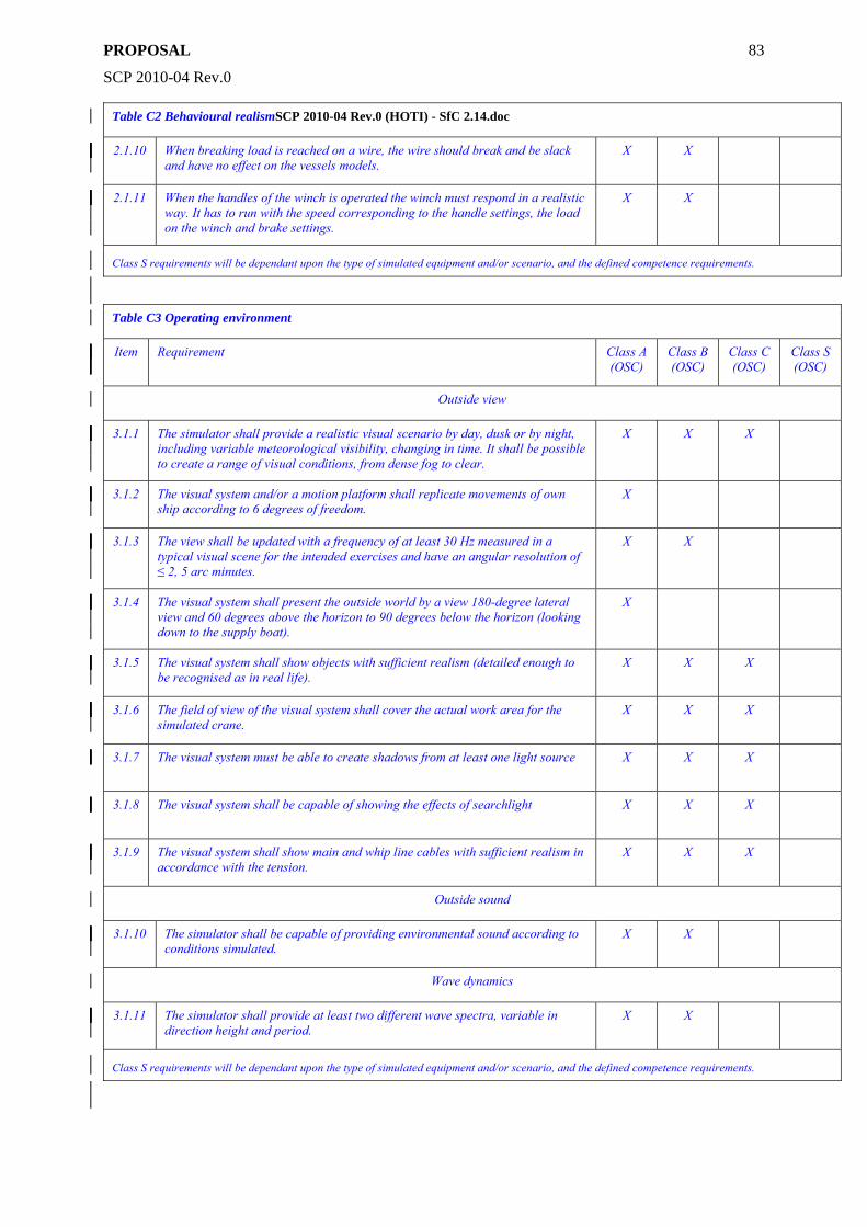
PROPOSAL
SCP 2010-04 Rev.0
83
Table C2 Behavioural realismSCP 2010-04 Rev.0 (HOTI) - SfC 2.14.doc
2.1.10 When breaking load is reached on a wire, the wire should break and be slack and have no effect on the vessels models.
X X
2.1.11 When the handles of the winch is operated the winch must respond in a realistic way. It has to run with the speed corresponding to the handle settings, the load on the winch and brake settings.
X X
Class S requirements will be dependant upon the type of simulated equipment and/or scenario, and the defined competence requirements.
Table C3 Operating environment
Item Requirement Class A (OSC)
Class B (OSC)
Class C (OSC)
Class S (OSC)
Outside view
3.1.1 The simulator shall provide a realistic visual scenario by day, dusk or by night, including variable meteorological visibility, changing in time. It shall be possible to create a range of visual conditions, from dense fog to clear.
X X X
3.1.2 The visual system and/or a motion platform shall replicate movements of own ship according to 6 degrees of freedom.
X
3.1.3 The view shall be updated with a frequency of at least 30 Hz measured in a typical visual scene for the intended exercises and have an angular resolution of ≤ 2, 5 arc minutes.
X X
3.1.4 The visual system shall present the outside world by a view 180-degree lateral view and 60 degrees above the horizon to 90 degrees below the horizon (looking down to the supply boat).
X
3.1.5 The visual system shall show objects with sufficient realism (detailed enough to be recognised as in real life).
X X X
3.1.6 The field of view of the visual system shall cover the actual work area for the simulated crane.
X X X
3.1.7 The visual system must be able to create shadows from at least one light source X X X
3.1.8 The visual system shall be capable of showing the effects of searchlight X X X
3.1.9 The visual system shall show main and whip line cables with sufficient realism in accordance with the tension.
X X X
Outside sound
3.1.10 The simulator shall be capable of providing environmental sound according to conditions simulated.
X X
Wave dynamics
3.1.11 The simulator shall provide at least two different wave spectra, variable in direction height and period.
X X
Class S requirements will be dependant upon the type of simulated equipment and/or scenario, and the defined competence requirements.
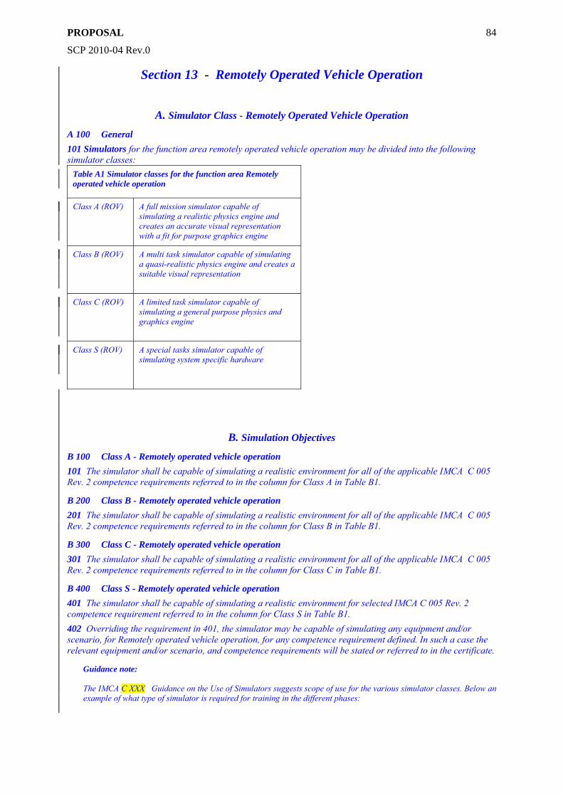
PROPOSAL
SCP 2010-04 Rev.0
84
Section 13 - Remotely Operated Vehicle Operation
A. Simulator Class - Remotely Operated Vehicle Operation
A 100 General 101 Simulators for the function area remotely operated vehicle operation may be divided into the following simulator classes:
Table A1 Simulator classes for the function area Remotely operated vehicle operation
Class A (ROV) A full mission simulator capable of simulating a realistic physics engine and creates an accurate visual representation with a fit for purpose graphics engine
Class B (ROV) A multi task simulator capable of simulating a quasi-realistic physics engine and creates a suitable visual representation
Class C (ROV) A limited task simulator capable of simulating a general purpose physics and graphics engine
Class S (ROV) A special tasks simulator capable of simulating system specific hardware
B. Simulation Objectives
B 100 Class A - Remotely operated vehicle operation 101 The simulator shall be capable of simulating a realistic environment for all of the applicable IMCA C 005 Rev. 2 competence requirements referred to in the column for Class A in Table B1.
B 200 Class B - Remotely operated vehicle operation 201 The simulator shall be capable of simulating a realistic environment for all of the applicable IMCA C 005 Rev. 2 competence requirements referred to in the column for Class B in Table B1.
B 300 Class C - Remotely operated vehicle operation 301 The simulator shall be capable of simulating a realistic environment for all of the applicable IMCA C 005 Rev. 2 competence requirements referred to in the column for Class C in Table B1.
B 400 Class S - Remotely operated vehicle operation 401 The simulator shall be capable of simulating a realistic environment for selected IMCA C 005 Rev. 2 competence requirement referred to in the column for Class S in Table B1. 402 Overriding the requirement in 401, the simulator may be capable of simulating any equipment and/or scenario, for Remotely operated vehicle operation, for any competence requirement defined. In such a case the relevant equipment and/or scenario, and competence requirements will be stated or referred to in the certificate.
Guidance note: The IMCA C XXX Guidance on the Use of Simulators suggests scope of use for the various simulator classes. Below an example of what type of simulator is required for training in the different phases:
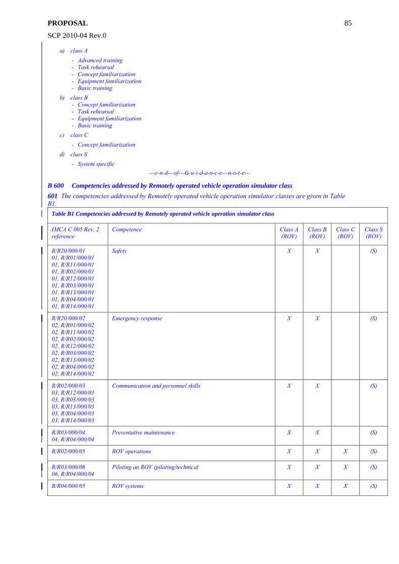
PROPOSAL
SCP 2010-04 Rev.0
85
a) class A - Advanced training - Task rehearsal - Concept familiarization - Equipment familiarization - Basic training
b) class B - Concept familiarization - Task rehearsal - Equipment familiarization - Basic training
c) class C - Concept familiarization
d) class S - System specific
---e-n-d---of---G-u-i-d-a-n-c-e---n-o-t-e---
B 600 Competencies addressed by Remotely operated vehicle operation simulator class 601 The competencies addressed by Remotely operated vehicle operation simulator classes are given in Table B1.
Table B1 Competencies addressed by Remotely operated vehicle operation simulator class
IMCA C 005 Rev. 2 reference
Competence Class A (ROV)
Class B (ROV)
Class C (ROV)
Class S (ROV)
R/R20/000/01 01, R/R01/000/01 01, R/R11/000/01 01, R/R02/000/01 01, R/R12/000/01 01, R/R03/000/01 01, R/R13/000/01 01, R/R04/000/01 01, R/R14/000/01
Safety X X (S)
R/R20/000/02 02, R/R01/000/02 02, R/R11/000/02 02, R/R02/000/02 02, R/R12/000/02 02, R/R03/000/02 02, R/R13/000/02 02, R/R04/000/02 02, R/R14/000/02
Emergency response X X (S)
R/R02/000/03 03, R/R12/000/03 03, R/R03/000/03 03, R/R13/000/03 03, R/R04/000/03 03, R/R14/000/03
Communication and personnel skills X X (S)
R/R03/000/04 04, R/R04/000/04
Preventative maintenance X X (S)
R/R02/000/05 ROV operations X X X (S)
R/R03/000/06 06, R/R04/000/04
Piloting an ROV (piloting/technical X X X (S)
R/R04/000/05 ROV systems X X X (S)
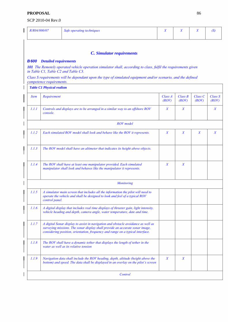
PROPOSAL
SCP 2010-04 Rev.0
86
R/R04/000/07 Safe operating techniques X X X (S)
C. Simulator requirements
B 600 Detailed requirements 101 The Remotely operated vehicle operation simulator shall, according to class, fulfil the requirements given in Table C1, Table C2 and Table C3. Class S requirements will be dependant upon the type of simulated equipment and/or scenario, and the defined competence requirements.
Table C1 Physical realism
Item Requirement Class A (ROV)
Class B (ROV)
Class C (ROV)
Class S (ROV)
1.1.1 Controls and displays are to be arranged in a similar way to an offshore ROV console.
X X X
ROV model
1.1.2 Each simulated ROV model shall look and behave like the ROV it represents.
X X X X
1.1.3 The ROV model shall have an altimeter that indicates its height above objects.
1.1.4 The ROV shall have at least one manipulator provided. Each simulated manipulator shall look and behaves like the manipulator it represents.
X X
Monitoring
1.1.5 A simulator main screen that includes all the information the pilot will need to operate the vehicle and shall be designed to look and feel of a typical ROV control panel.
1.1.6 A digital display that includes real time displays of thruster gain, light intensity, vehicle heading and depth, camera angle, water temperature, date and time.
1.1.7 A digital Sonar display to assist in navigation and obstacle avoidance as well as surveying missions. The sonar display shall provide an accurate sonar image, considering position, orientation, frequency and range on a typical interface.
1.1.8 The ROV shall have a dynamic tether that displays the length of tether in the water as well as its relative tension
1.1.9 Navigation data shall include the ROV heading, depth, altitude (height above the bottom) and speed. The data shall be displayed in an overlay on the pilot’s screen
X X
Control
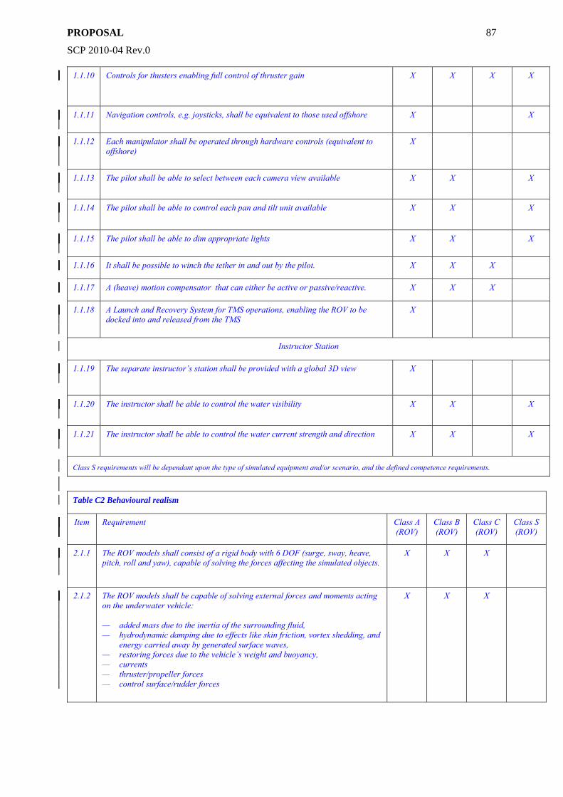
PROPOSAL
SCP 2010-04 Rev.0
87
1.1.10 Controls for thusters enabling full control of thruster gain X X X X
1.1.11 Navigation controls, e.g. joysticks, shall be equivalent to those used offshore
X X
1.1.12 Each manipulator shall be operated through hardware controls (equivalent to offshore)
X
1.1.13 The pilot shall be able to select between each camera view available
X X X
1.1.14 The pilot shall be able to control each pan and tilt unit available
X X X
1.1.15 The pilot shall be able to dim appropriate lights
X X X
1.1.16 It shall be possible to winch the tether in and out by the pilot. X X X
1.1.17 A (heave) motion compensator that can either be active or passive/reactive. X X X
1.1.18 A Launch and Recovery System for TMS operations, enabling the ROV to be docked into and released from the TMS
X
Instructor Station
1.1.19 The separate instructor’s station shall be provided with a global 3D view
X
1.1.20 The instructor shall be able to control the water visibility
X X X
1.1.21 The instructor shall be able to control the water current strength and direction
X X X
Class S requirements will be dependant upon the type of simulated equipment and/or scenario, and the defined competence requirements.
Table C2 Behavioural realism
Item Requirement Class A (ROV)
Class B (ROV)
Class C (ROV)
Class S (ROV)
2.1.1 The ROV models shall consist of a rigid body with 6 DOF (surge, sway, heave, pitch, roll and yaw), capable of solving the forces affecting the simulated objects.
X X X
2.1.2 The ROV models shall be capable of solving external forces and moments acting on the underwater vehicle: — added mass due to the inertia of the surrounding fluid, — hydrodynamic damping due to effects like skin friction, vortex shedding, and
energy carried away by generated surface waves, — restoring forces due to the vehicle’s weight and buoyancy, — currents — thruster/propeller forces — control surface/rudder forces
X X X
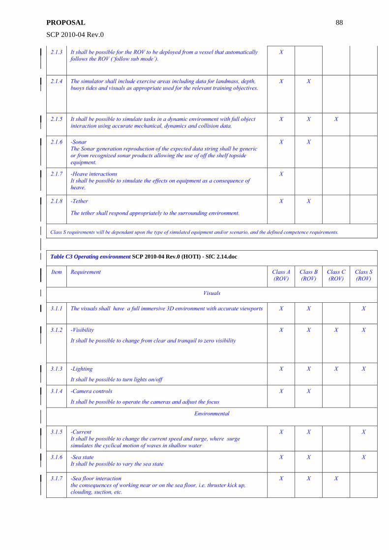
PROPOSAL
SCP 2010-04 Rev.0
88
2.1.3 It shall be possible for the ROV to be deployed from a vessel that automatically follows the ROV (‘follow sub mode’).
X
2.1.4 The simulator shall include exercise areas including data for landmass, depth, buoys tides and visuals as appropriate used for the relevant training objectives.
X X
2.1.5 It shall be possible to simulate tasks in a dynamic environment with full object interaction using accurate mechanical, dynamics and collision data.
X X X
2.1.6 -Sonar The Sonar generation reproduction of the expected data string shall be generic or from recognized sonar products allowing the use of off the shelf topside equipment.
X X
2.1.7 -Heave interactions It shall be possible to simulate the effects on equipment as a consequence of heave.
X
2.1.8 -Tether
The tether shall respond appropriately to the surrounding environment.
X X
Class S requirements will be dependant upon the type of simulated equipment and/or scenario, and the defined competence requirements.
Table C3 Operating environment SCP 2010-04 Rev.0 (HOTI) - SfC 2.14.doc
Item Requirement Class A (ROV)
Class B (ROV)
Class C (ROV)
Class S (ROV)
Visuals
3.1.1 The visuals shall have a full immersive 3D environment with accurate viewports X X X
3.1.2 -Visibility
It shall be possible to change from clear and tranquil to zero visibility
X X X X
3.1.3 -Lighting
It shall be possible to turn lights on/off
X X X X
3.1.4 -Camera controls
It shall be possible to operate the cameras and adjust the focus
X X
Environmental
3.1.5 -Current It shall be possible to change the current speed and surge, where surge simulates the cyclical motion of waves in shallow water
X X X
3.1.6 -Sea state It shall be possible to vary the sea state
X X X
3.1.7 -Sea floor interaction the consequences of working near or on the sea floor, i.e. thruster kick up, clouding, suction, etc.
X X X
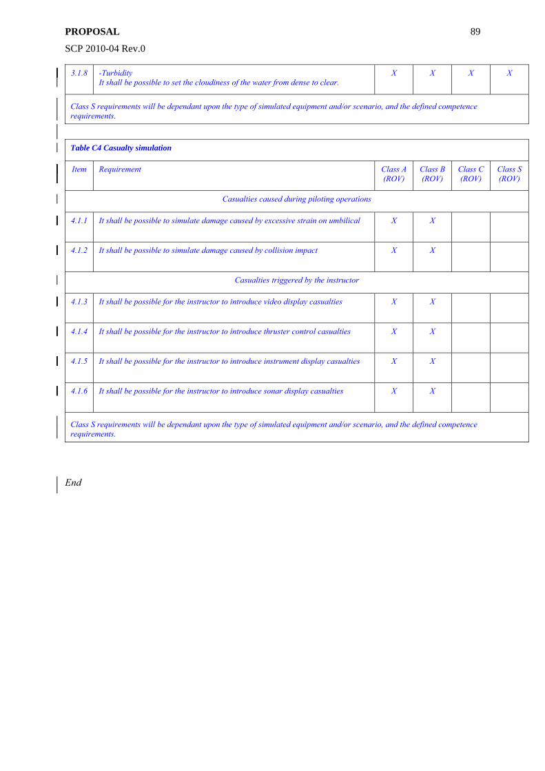
PROPOSAL
SCP 2010-04 Rev.0
89
3.1.8 -Turbidity It shall be possible to set the cloudiness of the water from dense to clear.
X X X X
Class S requirements will be dependant upon the type of simulated equipment and/or scenario, and the defined competence requirements.
Table C4 Casualty simulation
Item Requirement Class A (ROV)
Class B (ROV)
Class C (ROV)
Class S (ROV)
Casualties caused during piloting operations
4.1.1 It shall be possible to simulate damage caused by excessive strain on umbilical X X
4.1.2 It shall be possible to simulate damage caused by collision impact X X
Casualties triggered by the instructor
4.1.3 It shall be possible for the instructor to introduce video display casualties X X
4.1.4 It shall be possible for the instructor to introduce thruster control casualties X X
4.1.5 It shall be possible for the instructor to introduce instrument display casualties X X
4.1.6 It shall be possible for the instructor to introduce sonar display casualties X X
Class S requirements will be dependant upon the type of simulated equipment and/or scenario, and the defined competence requirements.
End
Related Documents