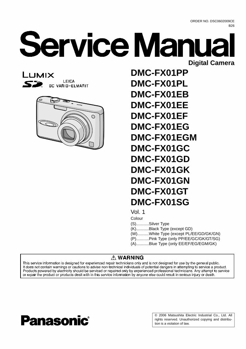
© 2006 Matsushita Electric Industrial Co., Ltd. All rights reserved. Unauthorized copying and distribu- tion is a violation of law. ORDER NO. DSC0602009CE B26 Digital Camera DMC-FX01PP DMC-FX01PL DMC-FX01EB DMC-FX01EE DMC-FX01EF DMC-FX01EG DMC-FX01EGM DMC-FX01GC DMC-FX01GD DMC-FX01GK DMC-FX01GN DMC-FX01GT DMC-FX01SG Vol. 1 Colour (S)...........Silver Type (K)...........Black Type (except GD) (W)..........White Type (except PL/EE/GD/GK/GN) (P)...........Pink Type (only PP/EE/GC/GK/GT/SG) (A)...........Blue Type (only EE/EF/EG/EGM/GK)

Welcome message from author
This document is posted to help you gain knowledge. Please leave a comment to let me know what you think about it! Share it to your friends and learn new things together.
Transcript
ORDER NO. DSC0602009CEB26
Digital CameraDMC-FX01PPDMC-FX01PLDMC-FX01EBDMC-FX01EEDMC-FX01EFDMC-FX01EGDMC-FX01EGMDMC-FX01GCDMC-FX01GDDMC-FX01GKDMC-FX01GNDMC-FX01GTDMC-FX01SGVol. 1Colour(S)...........Silver Type(K)...........Black Type (except GD)(W)..........White Type (except PL/EE/GD/GK/GN)(P)...........Pink Type (only PP/EE/GC/GK/GT/SG)(A)...........Blue Type (only EE/EF/EG/EGM/GK)
© 2006 Matsushita Electric Industrial Co., Ltd. Allrights reserved. Unauthorized copying and distribu-tion is a violation of law.
TABLE OF CONTENTSPAGE PAGE
1 Safety Precaution -------------------------------------------------31.1. General Guidelines ----------------------------------------31.2. Leakage Current Cold Check ---------------------------31.3. Leakage Current Hot Check (See Figure 1.)--------31.4. How to Discharge the Capacitor on Flash Top
PCB------------------------------------------------------------42 Warning --------------------------------------------------------------5
2.1. Prevention of Electro Static Discharge (ESD)to ElectrostaticallySensitive (ES) Devices -----------5
2.2. How to Recycle the Lithium Ion Battery (U.S.Only)-----------------------------------------------------------5
2.3. Caution for AC Cord(For EB/GC/SG) -----------------62.4. How to Replace the Lithium Battery-------------------7
3 Service Navigation------------------------------------------------93.1. Introduction --------------------------------------------------93.2. General Description About Lead Free Solder
(PbF) ----------------------------------------------------------93.3. Important Notice 1:(Other than U.S.A. and
Canadian Market) ------------------------------------------93.4. How to Define the Model Suffix (NTSC or PAL
model)------------------------------------------------------- 104 Specifications ---------------------------------------------------- 125 Location of Controls and Components------------------ 136 Service Mode ----------------------------------------------------- 14
6.1. Error Code Memory Function ------------------------- 146.2. Confirmation of Firmware Version ------------------- 17
7 Service Fixture & Tools --------------------------------------- 187.1. Service Fixture and Tools ------------------------------ 187.2. When Replacing the Main PCB ---------------------- 197.3. Service Position ------------------------------------------ 19
8 Disassembly and Assembly Instructions --------------- 208.1. Disassembly Flow Chart-------------------------------- 208.2. PCB Location---------------------------------------------- 208.3. Disassembly Procedure -------------------------------- 218.4. Disassembly Procedure for the Lens --------------- 248.5. Assembly Procedure for the Lens ------------------- 268.6. Removal of the CCD Unit ------------------------------ 298.7. The Applyment of Grease Method------------------- 29
9 Measurements and Adjustments -------------------------- 309.1. Matrix Chart for Replaced Part and Necessary
Adjustment------------------------------------------------- 3010 Maintenace -------------------------------------------------------- 31
10.1. Cleaning Lens and LCD Panel ----------------------- 31
2
1 Safety Precaution1.1. General Guidelines
1. IMPORTANT SAFETY NOTICEThere are special components used in this equipmentwhich are important for safety. These parts are marked by
in the Schematic Diagrams, Circuit Board Layout,Exploded Views and Replacement Parts List. It is essen-tial that these critical parts should be replaced with manu-facturer’s specified parts to prevent X-RADIATION,shock, fire, or other hazards. Do not modify the originaldesign without permission of manufacturer.
2. An Isolation Transformer should always be used duringthe servicing of AC Adaptor whose chassis is not isolatedfrom the AC power line. Use a transformer of adequatepower rating as this protects the technician from acci-dents resulting in personal injury from electrical shocks. Itwill also protect AC Adaptor from being damaged by acci-dental shorting that may occur during servicing.
3. When servicing, observe the original lead dress. If a shortcircuit is found, replace all parts which have been over-heated or damaged by the short circuit.
4. After servicing, see to it that all the protective devicessuch as insulation barriers, insulation papers shields areproperly installed.
5. After servicing, make the following leakage currentchecks to prevent the customer from being exposed toshock hazards.
1.2. Leakage Current Cold Check1. Unplug the AC cord and connect a jumper between the
two prongs on the plug.2. Measure the resistance value, with an ohmmeter,
between the jumpered AC plug and each exposed metal-lic cabinet part on the equipment such as screwheads,connectors, control shafts, etc. When the exposed metal-lic part has a return path to the chassis, the readingshould be between 1 MΩ and 5.2 MΩ. When the exposedmetal does not have a return path to the chassis, thereading must be infinity.
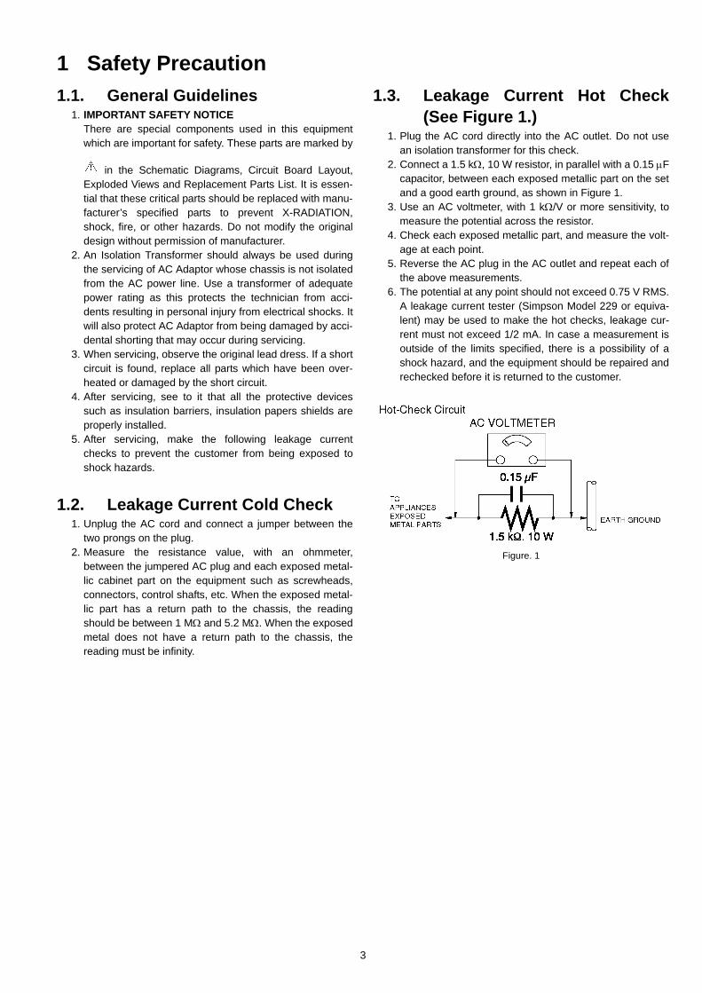
1.3. Leakage Current Hot Check(See Figure 1.)
1. Plug the AC cord directly into the AC outlet. Do not usean isolation transformer for this check.
2. Connect a 1.5 kΩ, 10 W resistor, in parallel with a 0.15 μFcapacitor, between each exposed metallic part on the setand a good earth ground, as shown in Figure 1.
3. Use an AC voltmeter, with 1 kΩ/V or more sensitivity, tomeasure the potential across the resistor.
4. Check each exposed metallic part, and measure the volt-age at each point.
5. Reverse the AC plug in the AC outlet and repeat each ofthe above measurements.
6. The potential at any point should not exceed 0.75 V RMS.A leakage current tester (Simpson Model 229 or equiva-lent) may be used to make the hot checks, leakage cur-rent must not exceed 1/2 mA. In case a measurement isoutside of the limits specified, there is a possibility of ashock hazard, and the equipment should be repaired andrechecked before it is returned to the customer.
Figure. 1
3
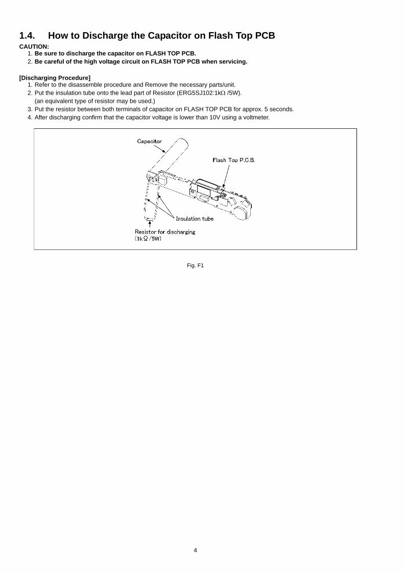
1.4. How to Discharge the Capacitor on Flash Top PCBCAUTION:
1. Be sure to discharge the capacitor on FLASH TOP PCB.2. Be careful of the high voltage circuit on FLASH TOP PCB when servicing.
[Discharging Procedure]1. Refer to the disassemble procedure and Remove the necessary parts/unit.2. Put the insulation tube onto the lead part of Resistor (ERG5SJ102:1kΩ /5W).
(an equivalent type of resistor may be used.)3. Put the resistor between both terminals of capacitor on FLASH TOP PCB for approx. 5 seconds.4. After discharging confirm that the capacitor voltage is lower than 10V using a voltmeter.
Fig. F1
4
2 Warning2.1. Prevention of Electro Static Discharge (ESD) to Electrostatically
Sensitive (ES) DevicesSome semiconductor (solid state) devices can be damaged easily by static electricity. Such components commonly are called Elec-trostatically Sensitive (ES) Devices.
The following techniques should be used to help reduce the incidence of component damage caused by electro static discharge(ESD).
1. Immediately before handling any semiconductor component or semiconductor-equipped assembly, drain off any ESD on yourbody by touching a known earth ground. Alternatively, obtain and wear a commercially available discharging ESD wrist strap,which should be removed for potential shock reasons prior to applying power to the unit under test.
2. After removing an electrical assembly equipped with ES devices, place the assembly on a conductive surface such as alumi-num foil, to prevent electrostatic charge buildup or exposure of the assembly.
3. Use only a grounded-tip soldering iron to solder or unsolder ES devices.4. Use only an antistatic solder removal device. Some solder removal devices not classified as "antistatic (ESD protected)" can
generate electrical charge sufficient to damage ES devices.5. Do not use freon-propelled chemicals. These can generate electrical charges sufficient to damage ES devices.6. Do not remove a replacement ES device from its protective package until immediately before you are ready to install it. (Most
replacement ES devices are packaged with leads electrically shorted together by conductive foam, aluminum foil or compara-ble conductive material).
7. Immediately before removing the protective material from the leads of a replacement ES device, touch the protective materialto the chassis or circuit assembly into which the device will be installed.CAUTION :
Be sure no power is applied to the chassis or circuit, and observe all other safety precautions.8. Minimize bodily motions when handling unpackaged replacement ES devices. (Otherwise harmless motion such as the
brushing together of your clothes fabric or the lifting of your foot from a carpeted floor can generate static electricity (ESD) suf-ficient to damage an ES device).
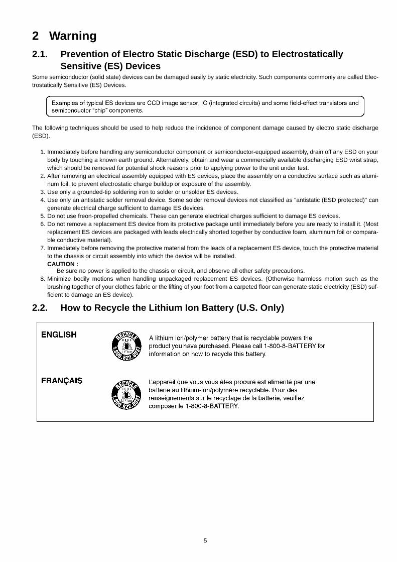
2.2. How to Recycle the Lithium Ion Battery (U.S. Only)
5
2.3. Caution for AC Cord(For EB/GC/SG)
2.3.1. Information for Your SafetyIMPORTANT
Your attention is drawn to the fact that recording of pre-recorded tapes or discs or other published or broadcastmaterial may infringe copyright laws.
WARNINGTo reduce the risk of fire or shock hazard, do not exposethis equipment to rain or moisture.
CAUTIONTo reduce the risk of fire or shock hazard and annoyinginterference, use the recommended accessories only.
FOR YOUR SAFETY DO NOT REMOVE THE OUTER COVERTo prevent electric shock, do not remove the cover. No userserviceable parts inside. Refer servicing to qualified servicepersonnel.
2.3.2. Caution for AC Mains LeadFor your safety, please read the following text carefully.
This appliance is supplied with a moulded three-pin mains plugfor your safety and convenience.A 5-ampere fuse is fitted in this plug.Should the fuse need to be replaced please ensure that thereplacement fuse has a rating of 5 amperes and it is approvedby ASTA or BSI to BS1362Check for the ASRA mark or the BSI mark on the body of thefuse.
If the plug contains a removable fuse cover you must ensurethat it is refitted when the fuse is replaced.If you lose the fuse cover, the plug must not be used until areplacement cover is obtained.A replacement fuse cover can be purchased from your localPanasonic Dealer.
If the fitted moulded plug is unsuitable for the socket outlet inyour home then the fuse should be removed and the plug cutoff and disposed of safety.There is a danger of severe electrical shock if the cut off plug isinserted into any 13-ampere socket.
If a new plug is to be fitted please observe the wiring code asshown below.If in any doubt, please consult a qualified electrician.
2.3.2.1. ImportantThe wires in this mains lead are coloured in accordance withthe following code:
As the colours of the wires in the mains lead of this appliancemay not correspond with the coloured markings identifying theterminals in your plug, proceed as follows:
The wire which is coloured BLUE must be connected to the ter-minal in the plug which is marked with the letter N or colouredBLACK.
The wire which is coloured BROWN must be connected to theterminal in the plug which is marked with the letter L or colouredRED.
Under no circumstances should either of these wires be con-nected to the earth terminal of the three pin plug, marked withthe letter E or the Earth Symbol.
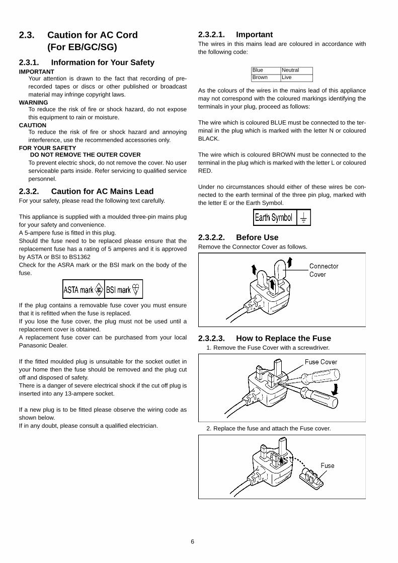
2.3.2.2. Before UseRemove the Connector Cover as follows.
2.3.2.3. How to Replace the Fuse1. Remove the Fuse Cover with a screwdriver.
2. Replace the fuse and attach the Fuse cover.
Blue NeutralBrown Live
6
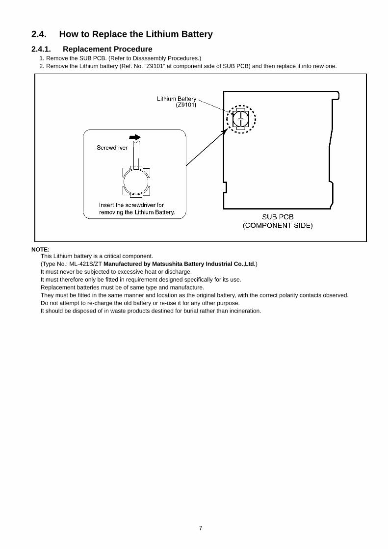
2.4. How to Replace the Lithium Battery2.4.1. Replacement Procedure
1. Remove the SUB PCB. (Refer to Disassembly Procedures.)2. Remove the Lithium battery (Ref. No. “Z9101” at component side of SUB PCB) and then replace it into new one.
NOTE:This Lithium battery is a critical component. (Type No.: ML-421S/ZT Manufactured by Matsushita Battery Industrial Co.,Ltd.)It must never be subjected to excessive heat or discharge.It must therefore only be fitted in requirement designed specifically for its use.Replacement batteries must be of same type and manufacture.They must be fitted in the same manner and location as the original battery, with the correct polarity contacts observed.Do not attempt to re-charge the old battery or re-use it for any other purpose.It should be disposed of in waste products destined for burial rather than incineration.
7
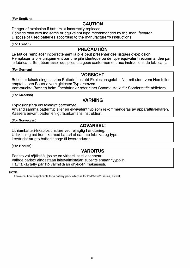
NOTE:Above caution is applicable for a battery pack which is for DMC-FX01 series, as well.
8
3 Service Navigation3.1. IntroductionThis service manual contains technical information, which allow service personnel’s to understand and service this model.Please place orders using the parts list and not the drawing reference numbers.If the circuit is changed or modified, the information will be followed by service manual to be controlled with original service manual.
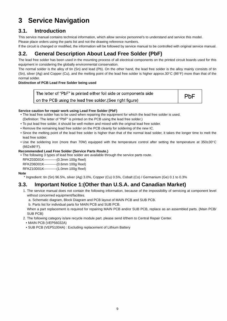
3.2. General Description About Lead Free Solder (PbF)The lead free solder has been used in the mounting process of all electrical components on the printed circuit boards used for thisequipment in considering the globally environmental conservation.The normal solder is the alloy of tin (Sn) and lead (Pb). On the other hand, the lead free solder is the alloy mainly consists of tin(Sn), silver (Ag) and Copper (Cu), and the melting point of the lead free solder is higher approx.30°C (86°F) more than that of thenormal solder.Distinction of PCB Lead Free Solder being used
Service caution for repair work using Lead Free Solder (PbF)• The lead free solder has to be used when repairing the equipment for which the lead free solder is used.
(Definition: The letter of “PbF” is printed on the PCB using the lead free solder.)• To put lead free solder, it should be well molten and mixed with the original lead free solder.• Remove the remaining lead free solder on the PCB cleanly for soldering of the new IC.• Since the melting point of the lead free solder is higher than that of the normal lead solder, it takes the longer time to melt the
lead free solder.• Use the soldering iron (more than 70W) equipped with the temperature control after setting the temperature at 350±30°C
(662±86°F).Recommended Lead Free Solder (Service Parts Route.)
• The following 3 types of lead free solder are available through the service parts route.RFKZ03D01K-----------(0.3mm 100g Reel)RFKZ06D01K-----------(0.6mm 100g Reel)RFKZ10D01K-----------(1.0mm 100g Reel)
Note* Ingredient: tin (Sn) 96.5%, silver (Ag) 3.0%, Copper (Cu) 0.5%, Cobalt (Co) / Germanium (Ge) 0.1 to 0.3%
3.3. Important Notice 1:(Other than U.S.A. and Canadian Market)1. The service manual does not contain the following information, because of the impossibility of servicing at component level
without concerned equipment/facilites.a. Schematic diagram, Block Diagram and PCB layout of MAIN PCB and SUB PCB.b. Parts list for individual parts for MAIN PCB and SUB PCB.
When a part replacement is required for repairing MAIN PCB and/or SUB PCB, replace as an assembled parts. (Main PCB/SUB PCB)
2. The following category is/are recycle module part. please send it/them to Central Repair Center.• MAIN PCB (VEP56032A)• SUB PCB (VEP51004A) : Excluding replacement of Lithium Battery
9
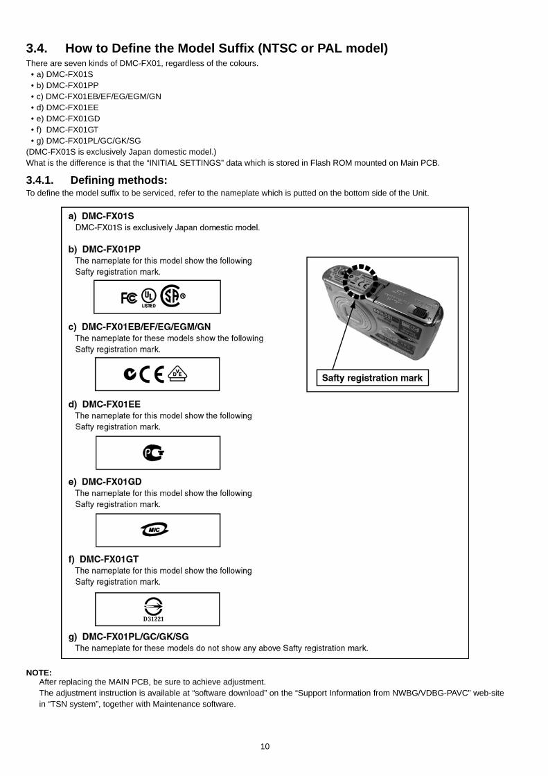
3.4. How to Define the Model Suffix (NTSC or PAL model)There are seven kinds of DMC-FX01, regardless of the colours.
• a) DMC-FX01S• b) DMC-FX01PP• c) DMC-FX01EB/EF/EG/EGM/GN• d) DMC-FX01EE• e) DMC-FX01GD• f) DMC-FX01GT• g) DMC-FX01PL/GC/GK/SG
(DMC-FX01S is exclusively Japan domestic model.)What is the difference is that the “INITIAL SETTINGS” data which is stored in Flash ROM mounted on Main PCB.
3.4.1. Defining methods:To define the model suffix to be serviced, refer to the nameplate which is putted on the bottom side of the Unit.
NOTE:After replacing the MAIN PCB, be sure to achieve adjustment.The adjustment instruction is available at “software download” on the “Support Information from NWBG/VDBG-PAVC” web-sitein “TSN system”, together with Maintenance software.
10
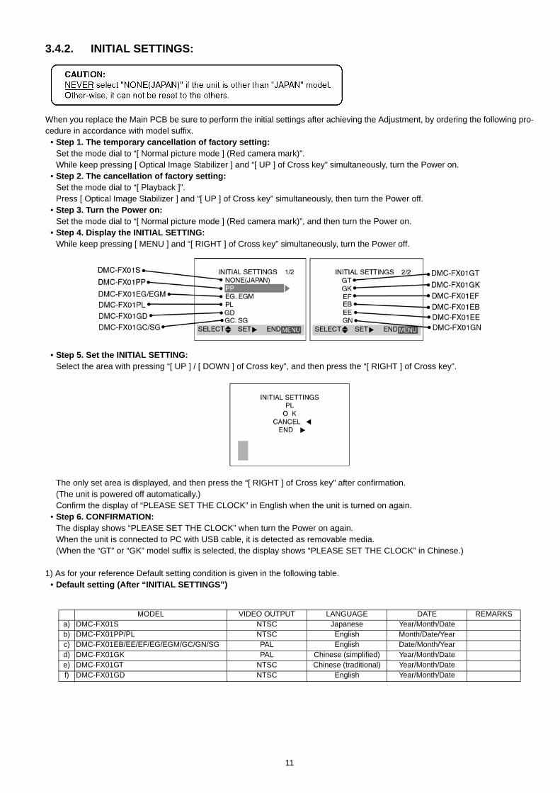
3.4.2. INITIAL SETTINGS:
When you replace the Main PCB be sure to perform the initial settings after achieving the Adjustment, by ordering the following pro-cedure in accordance with model suffix.
• Step 1. The temporary cancellation of factory setting:Set the mode dial to “[ Normal picture mode ] (Red camera mark)”. While keep pressing [ Optical Image Stabilizer ] and “[ UP ] of Cross key” simultaneously, turn the Power on.
• Step 2. The cancellation of factory setting:Set the mode dial to “[ Playback ]”.Press [ Optical Image Stabilizer ] and “[ UP ] of Cross key” simultaneously, then turn the Power off.
• Step 3. Turn the Power on:Set the mode dial to “[ Normal picture mode ] (Red camera mark)”, and then turn the Power on.
• Step 4. Display the INITIAL SETTING:While keep pressing [ MENU ] and “[ RIGHT ] of Cross key” simultaneously, turn the Power off.
• Step 5. Set the INITIAL SETTING:Select the area with pressing “[ UP ] / [ DOWN ] of Cross key”, and then press the “[ RIGHT ] of Cross key”.
The only set area is displayed, and then press the “[ RIGHT ] of Cross key” after confirmation.(The unit is powered off automatically.) Confirm the display of “PLEASE SET THE CLOCK” in English when the unit is turned on again.
• Step 6. CONFIRMATION:The display shows “PLEASE SET THE CLOCK” when turn the Power on again.When the unit is connected to PC with USB cable, it is detected as removable media.(When the “GT” or “GK” model suffix is selected, the display shows “PLEASE SET THE CLOCK” in Chinese.)
1) As for your reference Default setting condition is given in the following table.• Default setting (After “INITIAL SETTINGS”)
MODEL VIDEO OUTPUT LANGUAGE DATE REMARKSa) DMC-FX01S NTSC Japanese Year/Month/Dateb) DMC-FX01PP/PL NTSC English Month/Date/Yearc) DMC-FX01EB/EE/EF/EG/EGM/GC/GN/SG PAL English Date/Month/Yeard) DMC-FX01GK PAL Chinese (simplified) Year/Month/Datee) DMC-FX01GT NTSC Chinese (traditional) Year/Month/Datef) DMC-FX01GD NTSC English Year/Month/Date
11
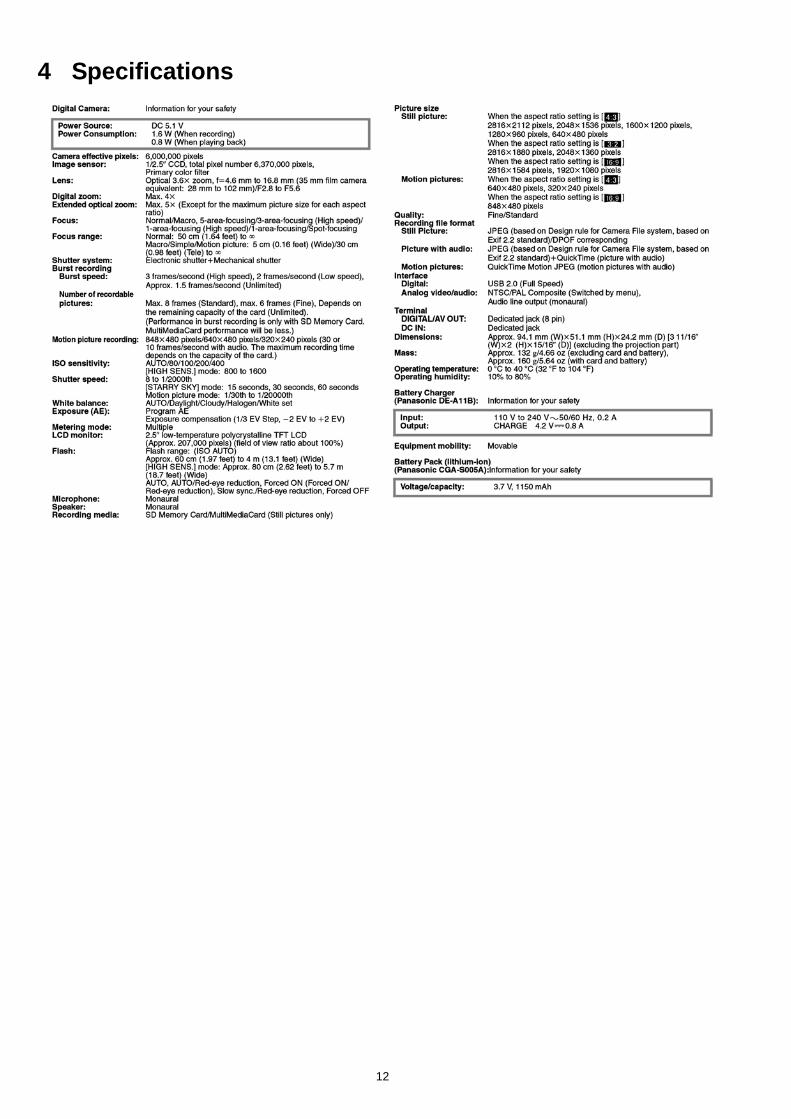
4 Specifications
12
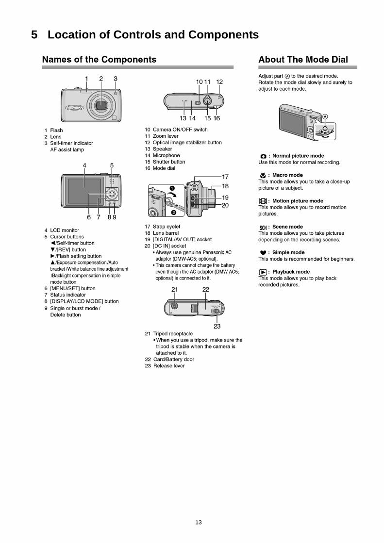
5 Location of Controls and Components
13
6 Service Mode6.1. Error Code Memory Function
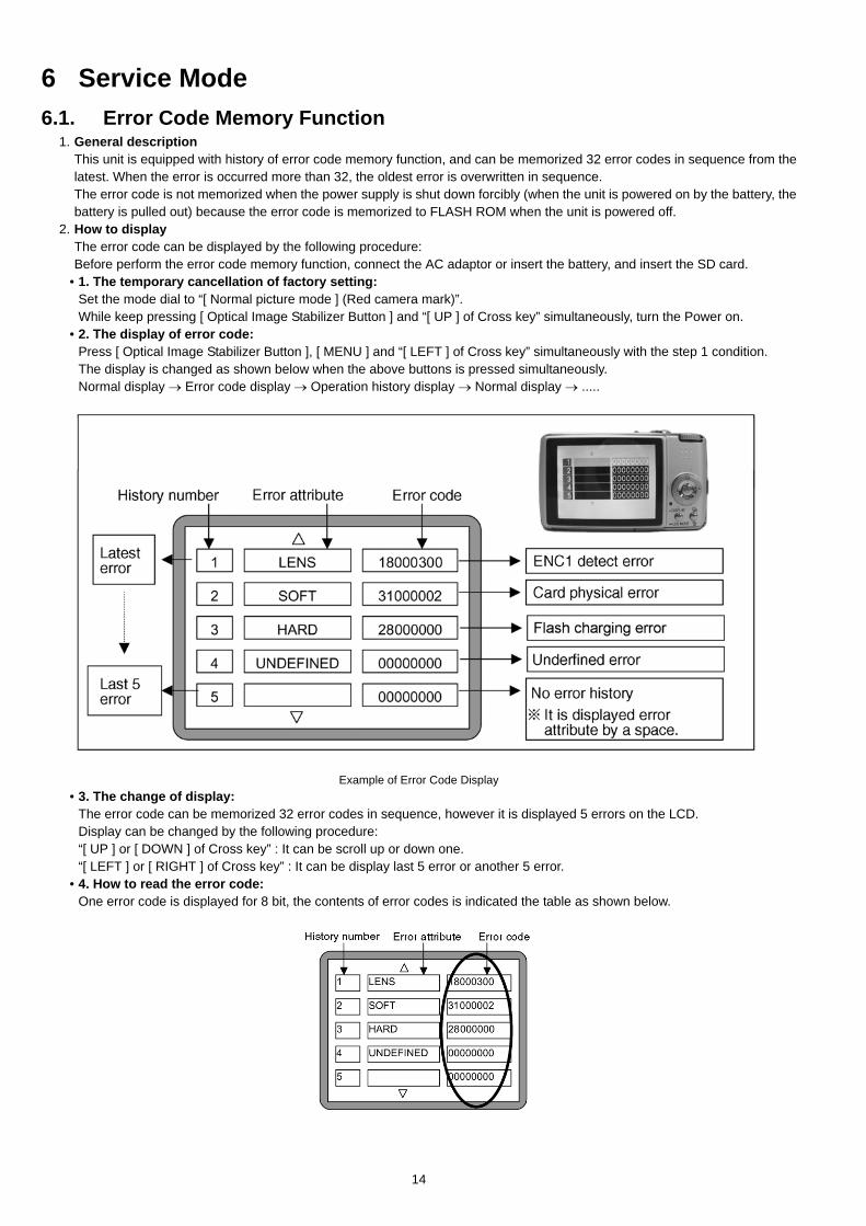
1. General descriptionThis unit is equipped with history of error code memory function, and can be memorized 32 error codes in sequence from thelatest. When the error is occurred more than 32, the oldest error is overwritten in sequence.The error code is not memorized when the power supply is shut down forcibly (when the unit is powered on by the battery, thebattery is pulled out) because the error code is memorized to FLASH ROM when the unit is powered off.
2. How to displayThe error code can be displayed by the following procedure:Before perform the error code memory function, connect the AC adaptor or insert the battery, and insert the SD card.
• 1. The temporary cancellation of factory setting:Set the mode dial to “[ Normal picture mode ] (Red camera mark)”.While keep pressing [ Optical Image Stabilizer Button ] and “[ UP ] of Cross key” simultaneously, turn the Power on.
• 2. The display of error code:Press [ Optical Image Stabilizer Button ], [ MENU ] and “[ LEFT ] of Cross key” simultaneously with the step 1 condition.The display is changed as shown below when the above buttons is pressed simultaneously.Normal display → Error code display → Operation history display → Normal display → .....
Example of Error Code Display• 3. The change of display:
The error code can be memorized 32 error codes in sequence, however it is displayed 5 errors on the LCD.Display can be changed by the following procedure:“[ UP ] or [ DOWN ] of Cross key” : It can be scroll up or down one.“[ LEFT ] or [ RIGHT ] of Cross key” : It can be display last 5 error or another 5 error.
• 4. How to read the error code:One error code is displayed for 8 bit, the contents of error codes is indicated the table as shown below.
14
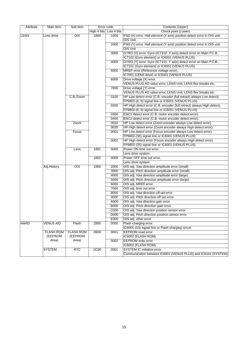
Attribute Main item Sub item Error code Contents (Upper)High 4 bits Low 4 bits Check point (Lower)
LENS Lens drive OIS 1800 1000 PSD (X) error. Hall element (X axis) position detect error in OIS unit.OIS Unit
2000 PSD (Y) error. Hall element (Y axis) position detect error in OIS unit.OIS Unit
3000 GYRO (X) error. Gyro (IC7102: X axis) detect error on Main P.C.B..IC7102 (Gyro element) or IC6001 (VENUS PLUS)
4000 GYRO (Y) error. Gyro (IC7101: Y axis) detect error on Main P.C.B..IC7101 (Gyro element) or IC6001 (VENUS PLUS)
5000 MREF error (Reference voltage error).IC7001 (LENS drive) or IC6001 (VENUS PLUS)
6000 Drive voltage (X) error.VENUS PLUS AD value error, LENS Unit, LENS flex breaks etc.
7000 Drive voltage (Y) error.VENUS PLUS AD value error, LENS Unit, LENS flex breaks etc.
C.B./Zoom 0100 HP Low detect error (C.B. encoder (full retract) always Low detect).FP9802-(6, 9) signal line or IC6001 (VENUS PLUS)
0200 HP High detect error (C.B. encoder (full retract) always High detect).FP9802-(6, 9) signal line or IC6001 (VENUS PLUS)
0300 ENC1 detect error (C.B. motor encoder detect error).0400 ENC2 detect error (C.B. motor encoder detect error).
Zoom 0010 HP Low detect error (Zoom encoder always Low detect error).0020 HP High detect error (Zoom encoder always High detect error).
Focus 0001 HP Low detect error (Focus encoder always Low detect error).FP9802-(35) signal line or IC6001 (VENUS PLUS)
0002 HP High detect error (Focus encoder always High detect error).FP9802-(35) signal line or IC6001 (VENUS PLUS)
Lens 1801 0000 Power ON time out error.Lens drive system
1802 0000 Power OFF time out error.Lens drive system
Adj.History OIS 1900 2000 OIS adj. Yaw direction amplitude error (small)3000 OIS adj. Pitch direction amplitude error (small)4000 OIS adj. Yaw direction amplitude error (large)5000 OIS adj. Pitch direction amplitude error (large)6000 OIS adj. MREF error7000 OIS adj. time out error8000 OIS adj. Yaw direction off set error9000 OIS adj. Pitch direction off set errorA000 OIS adj. Yaw direction gain errorB000 OIS adj. Pitch direction gain errorC000 OIS adj. Yaw direction position sensor errorD000 OIS adj. Pitch direction position sensor errorE000 OIS adj. other error
HARD VENUS A/D Flash 2800 0000 Flash charging error.IC6001-(13) signal line or Flash charging circuit
FLASH ROM(EEPROM
Area)
FLASH ROM(EEPROM
Area)
2B00 0001 EEPROM read errorIC6002 (FLASH ROM)
0002 EEPROM write errorIC6002 (FLASH ROM)
SYSTEM RTC 2C00 0001 SYSTEM IC initialize errorCommunication between IC6001 (VENUS PLUS) and IC9101 (SYSTEM)
15
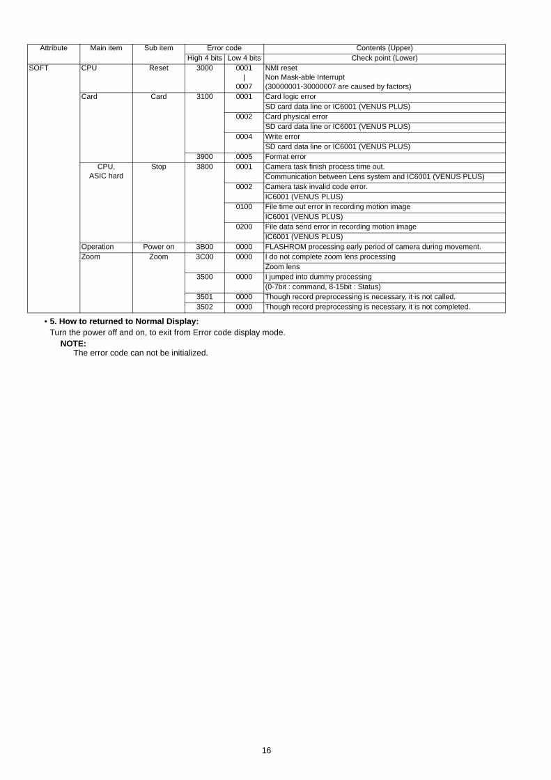
• 5. How to returned to Normal Display:Turn the power off and on, to exit from Error code display mode.
NOTE:The error code can not be initialized.
SOFT CPU Reset 3000 0001|
0007
NMI resetNon Mask-able Interrupt(30000001-30000007 are caused by factors)
Card Card 3100 0001 Card logic errorSD card data line or IC6001 (VENUS PLUS)
0002 Card physical errorSD card data line or IC6001 (VENUS PLUS)
0004 Write errorSD card data line or IC6001 (VENUS PLUS)
3900 0005 Format errorCPU,
ASIC hardStop 3800 0001 Camera task finish process time out.
Communication between Lens system and IC6001 (VENUS PLUS)0002 Camera task invalid code error.
IC6001 (VENUS PLUS)0100 File time out error in recording motion image
IC6001 (VENUS PLUS)0200 File data send error in recording motion image
IC6001 (VENUS PLUS)Operation Power on 3B00 0000 FLASHROM processing early period of camera during movement.Zoom Zoom 3C00 0000 I do not complete zoom lens processing
Zoom lens3500 0000 I jumped into dummy processing
(0-7bit : command, 8-15bit : Status)3501 0000 Though record preprocessing is necessary, it is not called.3502 0000 Though record preprocessing is necessary, it is not completed.
Attribute Main item Sub item Error code Contents (Upper)High 4 bits Low 4 bits Check point (Lower)
16
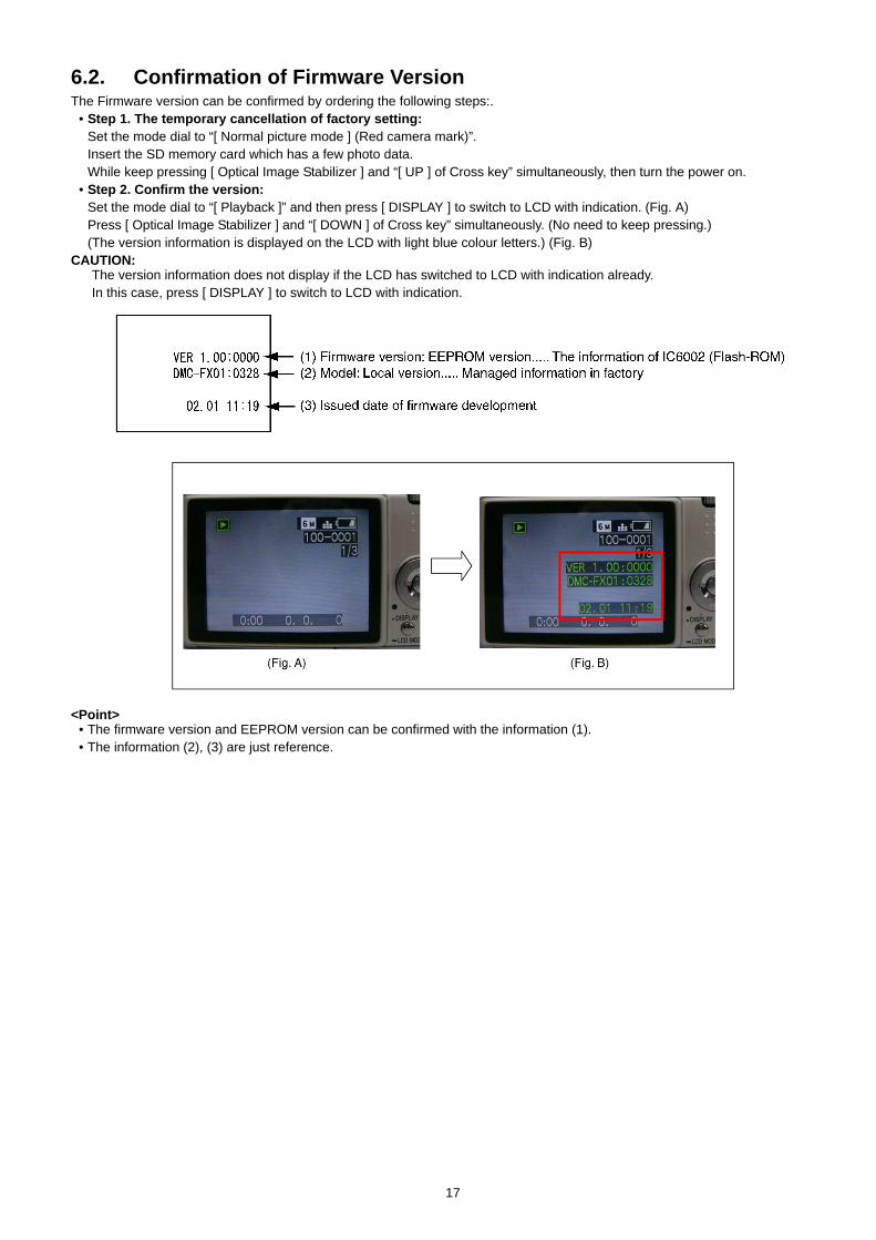
6.2. Confirmation of Firmware VersionThe Firmware version can be confirmed by ordering the following steps:.
• Step 1. The temporary cancellation of factory setting:Set the mode dial to “[ Normal picture mode ] (Red camera mark)”. Insert the SD memory card which has a few photo data.While keep pressing [ Optical Image Stabilizer ] and “[ UP ] of Cross key” simultaneously, then turn the power on.
• Step 2. Confirm the version:Set the mode dial to “[ Playback ]” and then press [ DISPLAY ] to switch to LCD with indication. (Fig. A)Press [ Optical Image Stabilizer ] and “[ DOWN ] of Cross key” simultaneously. (No need to keep pressing.)(The version information is displayed on the LCD with light blue colour letters.) (Fig. B)
CAUTION:The version information does not display if the LCD has switched to LCD with indication already.In this case, press [ DISPLAY ] to switch to LCD with indication.
<Point>• The firmware version and EEPROM version can be confirmed with the information (1).• The information (2), (3) are just reference.
17
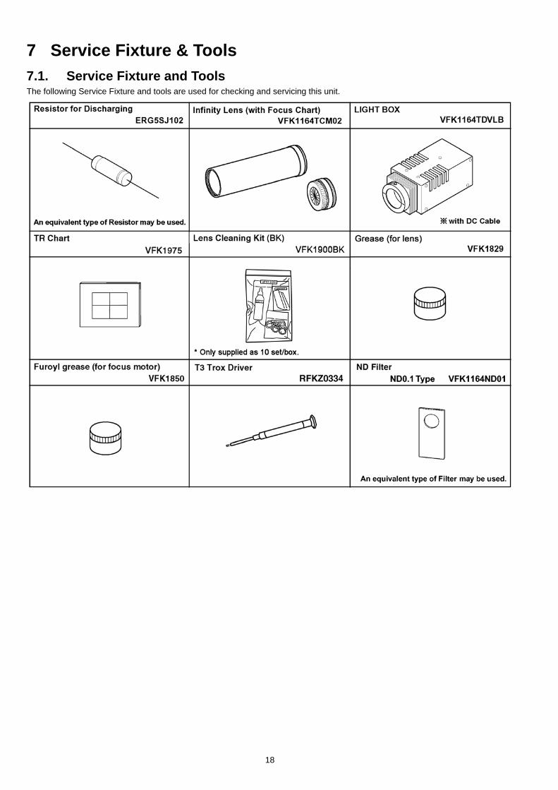
7 Service Fixture & Tools7.1. Service Fixture and ToolsThe following Service Fixture and tools are used for checking and servicing this unit.
18
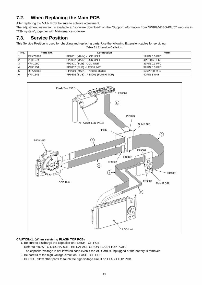
7.2. When Replacing the Main PCBAfter replacing the MAIN PCB, be sure to achieve adjustment.The adjustment instruction is available at “software download” on the “Support Information from NWBG/VDBG-PAVC” web-site in“TSN system”, together with Maintenance software.
7.3. Service PositionThis Service Position is used for checking and replacing parts. Use the following Extension cables for servicing.
Table S1 Extension Cable List
CAUTION-1. (When servicing FLASH TOP PCB)1. Be sure to discharge the capacitor on FLASH TOP PCB.
Refer to “HOW TO DISCHARGE THE CAPACITOR ON FLASH TOP PCB”.The capacitor voltage is not lowered soon even if the AC Cord is unplugged or the battery is removed.
2. Be careful of the high voltage circuit on FLASH TOP PCB.3. DO NOT allow other parts to touch the high voltage circuit on FLASH TOP PCB.
No. Parts No. Connection Form1 RFKZ0363 FP9001 (MAIN) - LCD UNIT 19PIN 0.5 FFC2 VFK1974 FP9002 (MAIN) - LCD UNIT 4PIN 0.5 FFC3 VFK1950 FP9801 (SUB) - CCD UNIT 33PIN 0.3 FFC4 VFK1951 FP9802 (SUB) - LENS UNIT 39PIN 0.3 FFC5 RFKZ0362 PP9001 (MAIN) - PS9801 (SUB) 100PIN B to B6 VFK1541 PP9802 (SUB) - PS8001 (FLASH TOP) 40PIN B to B
19
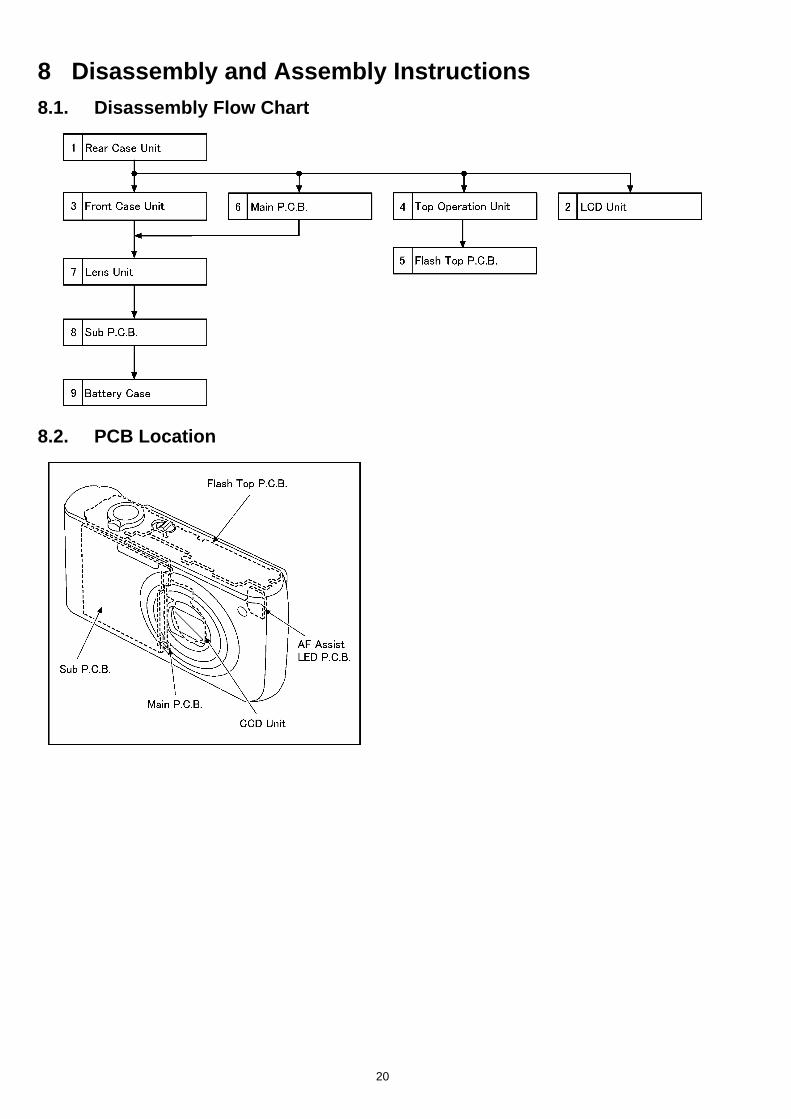
8 Disassembly and Assembly Instructions8.1. Disassembly Flow Chart
8.2. PCB Location
20
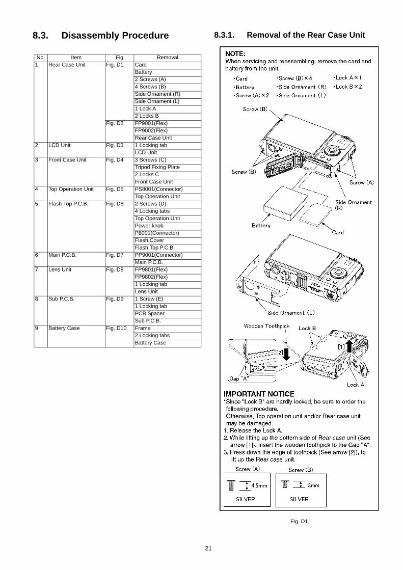
8.3. Disassembly Procedure 8.3.1. Removal of the Rear Case Unit
Fig. D1
No. Item Fig Removal1 Rear Case Unit Fig. D1 Card
Battery2 Screws (A)4 Screws (B)Side Ornament (R)Side Ornament (L)1 Lock A2 Locks B
Fig. D2 FP9001(Flex)FP9002(Flex)Rear Case Unit
2 LCD Unit Fig. D3 1 Locking tabLCD Unit
3 Front Case Unit Fig. D4 3 Screws (C)Tripod Fixing Plate2 Locks CFront Case Unit
4 Top Operation Unit Fig. D5 PS8001(Connector)Top Operation Unit
5 Flash Top P.C.B. Fig. D6 2 Screws (D)4 Locking tabsTop Operation UnitPower knobP8001(Connector)Flash CoverFlash Top P.C.B.
6 Main P.C.B. Fig. D7 PP9001(Connector)Main P.C.B.
7 Lens Unit Fig. D8 FP9801(Flex)FP9802(Flex)1 Locking tabLens Unit
8 Sub P.C.B. Fig. D9 1 Screw (E)1 Locking tabPCB SpacerSub P.C.B.
9 Battery Case Fig. D10 Frame2 Locking tabsBattery Case
21
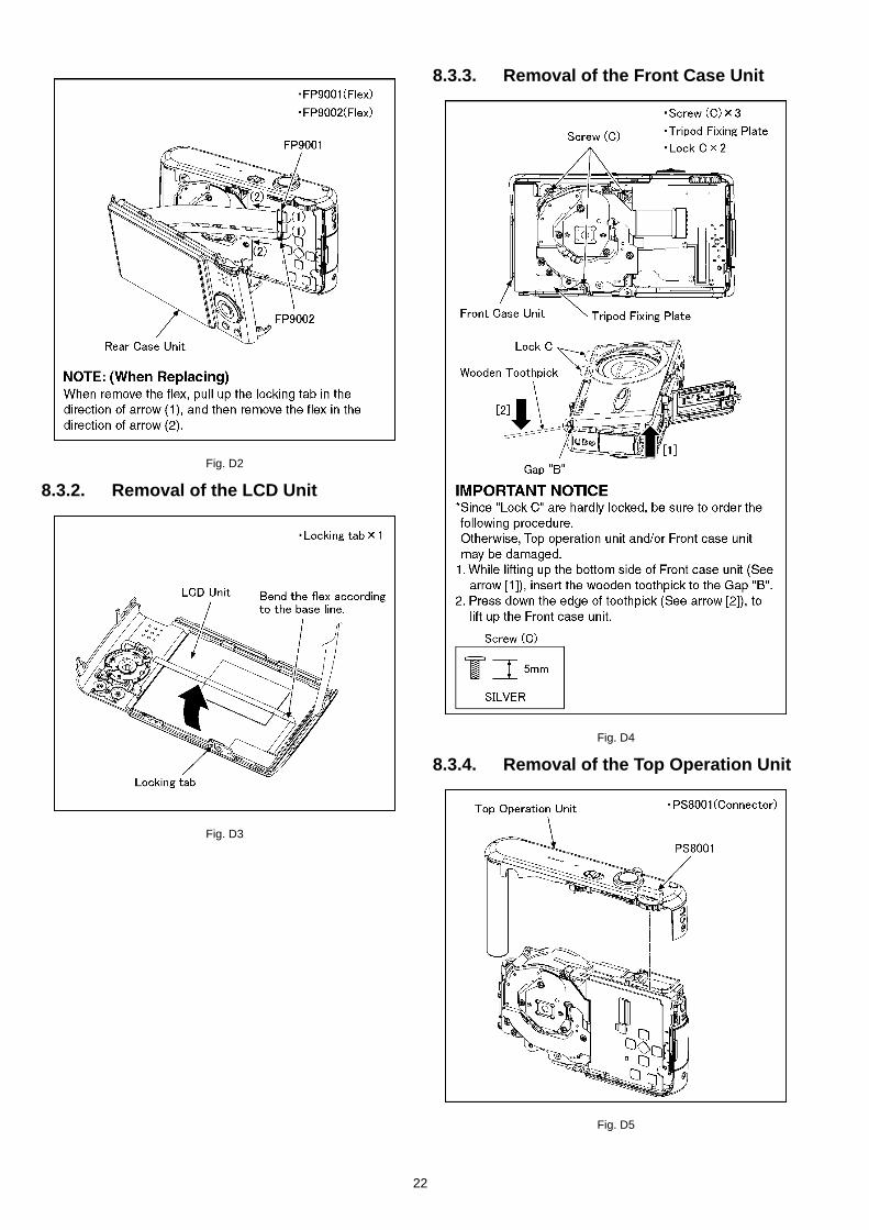
Fig. D2
8.3.2. Removal of the LCD Unit
Fig. D3
8.3.3. Removal of the Front Case Unit
Fig. D4
8.3.4. Removal of the Top Operation Unit
Fig. D5
22
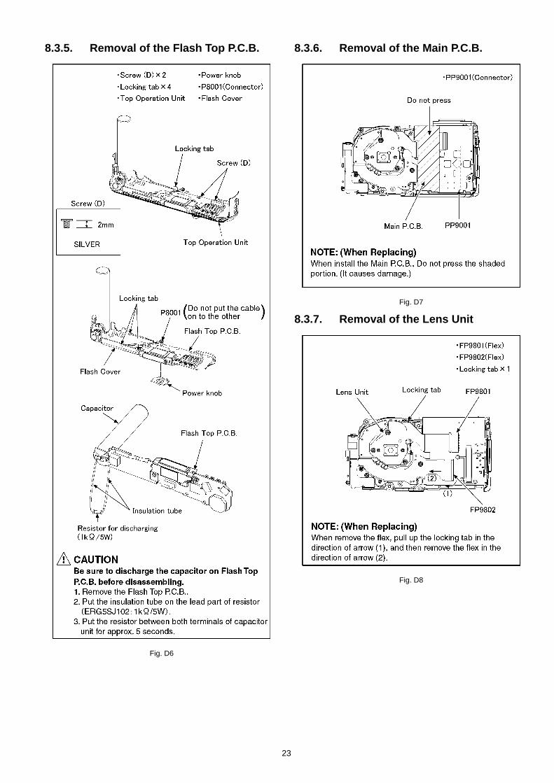
8.3.5. Removal of the Flash Top P.C.B.
Fig. D6
8.3.6. Removal of the Main P.C.B.
Fig. D7
8.3.7. Removal of the Lens Unit
Fig. D8
23
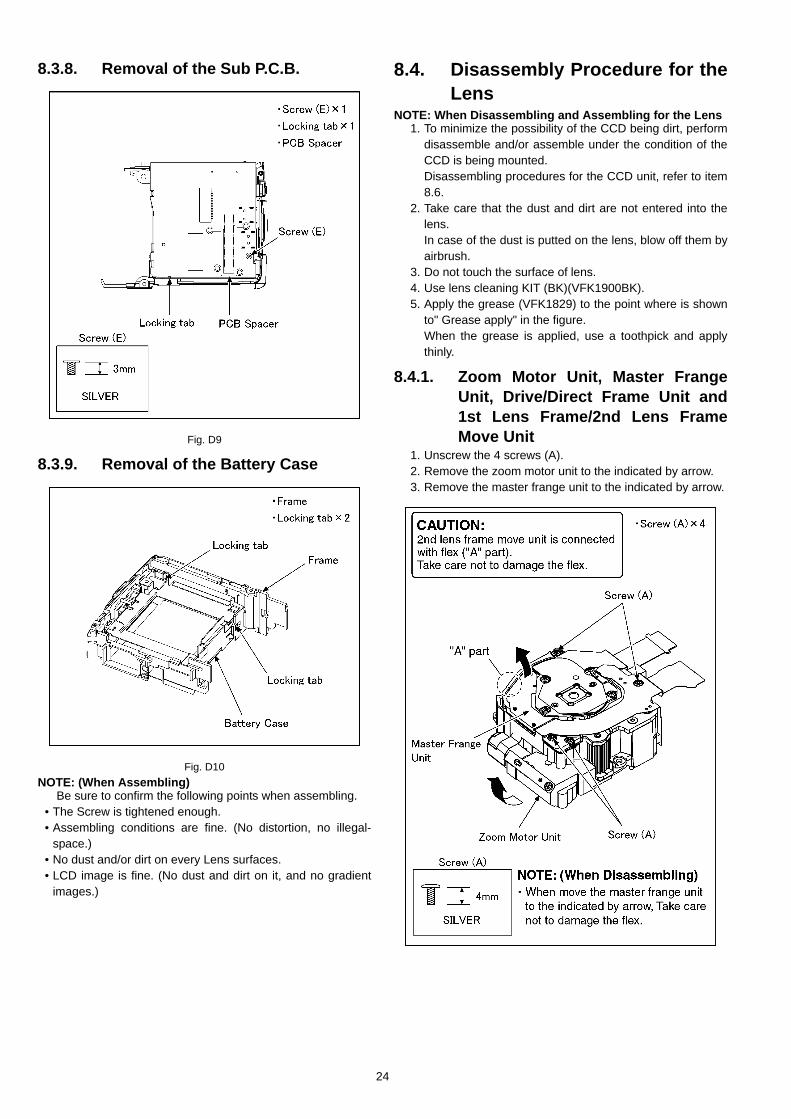
8.3.8. Removal of the Sub P.C.B.
Fig. D9
8.3.9. Removal of the Battery Case
Fig. D10NOTE: (When Assembling)
Be sure to confirm the following points when assembling.• The Screw is tightened enough.• Assembling conditions are fine. (No distortion, no illegal-
space.)• No dust and/or dirt on every Lens surfaces.• LCD image is fine. (No dust and dirt on it, and no gradient
images.)
8.4. Disassembly Procedure for theLens
NOTE: When Disassembling and Assembling for the Lens1. To minimize the possibility of the CCD being dirt, perform
disassemble and/or assemble under the condition of theCCD is being mounted. Disassembling procedures for the CCD unit, refer to item8.6.
2. Take care that the dust and dirt are not entered into thelens.In case of the dust is putted on the lens, blow off them byairbrush.
3. Do not touch the surface of lens.4. Use lens cleaning KIT (BK)(VFK1900BK).5. Apply the grease (VFK1829) to the point where is shown
to" Grease apply" in the figure.When the grease is applied, use a toothpick and applythinly.
8.4.1. Zoom Motor Unit, Master FrangeUnit, Drive/Direct Frame Unit and1st Lens Frame/2nd Lens FrameMove Unit
1. Unscrew the 4 screws (A).2. Remove the zoom motor unit to the indicated by arrow.3. Remove the master frange unit to the indicated by arrow.
24
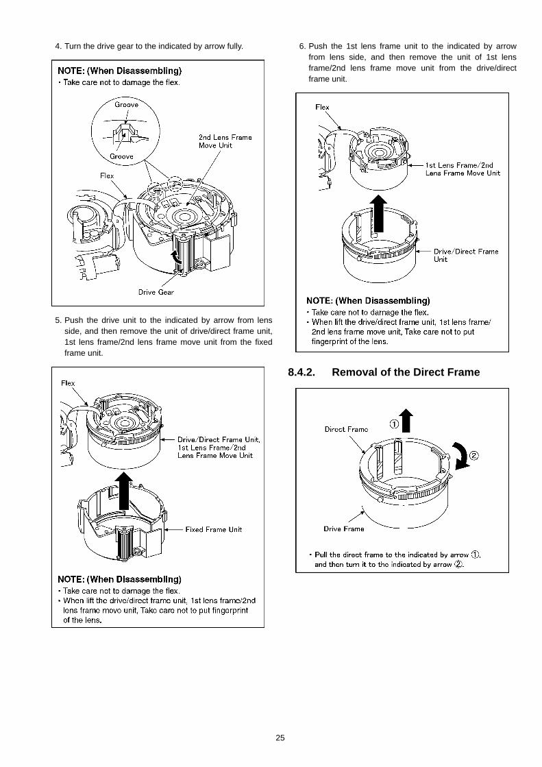
4. Turn the drive gear to the indicated by arrow fully.
5. Push the drive unit to the indicated by arrow from lensside, and then remove the unit of drive/direct frame unit,1st lens frame/2nd lens frame move unit from the fixedframe unit.
6. Push the 1st lens frame unit to the indicated by arrowfrom lens side, and then remove the unit of 1st lensframe/2nd lens frame move unit from the drive/directframe unit.
8.4.2. Removal of the Direct Frame
25
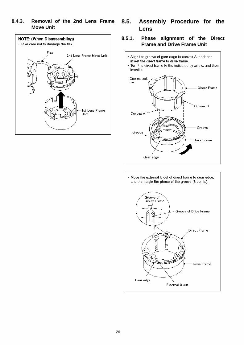
8.4.3. Removal of the 2nd Lens FrameMove Unit
8.5. Assembly Procedure for theLens
8.5.1. Phase alignment of the DirectFrame and Drive Frame Unit
26
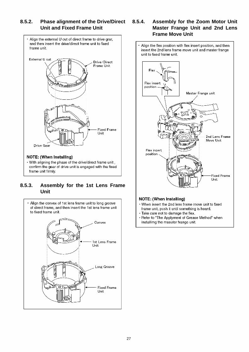
8.5.2. Phase alignment of the Drive/DirectUnit and Fixed Frame Unit
8.5.3. Assembly for the 1st Lens FrameUnit
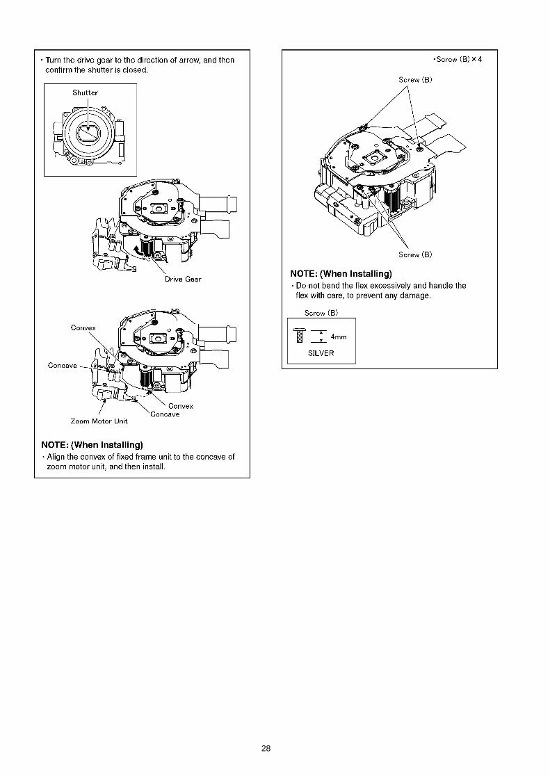
8.5.4. Assembly for the Zoom Motor UnitMaster Frange Unit and 2nd LensFrame Move Unit
27
28
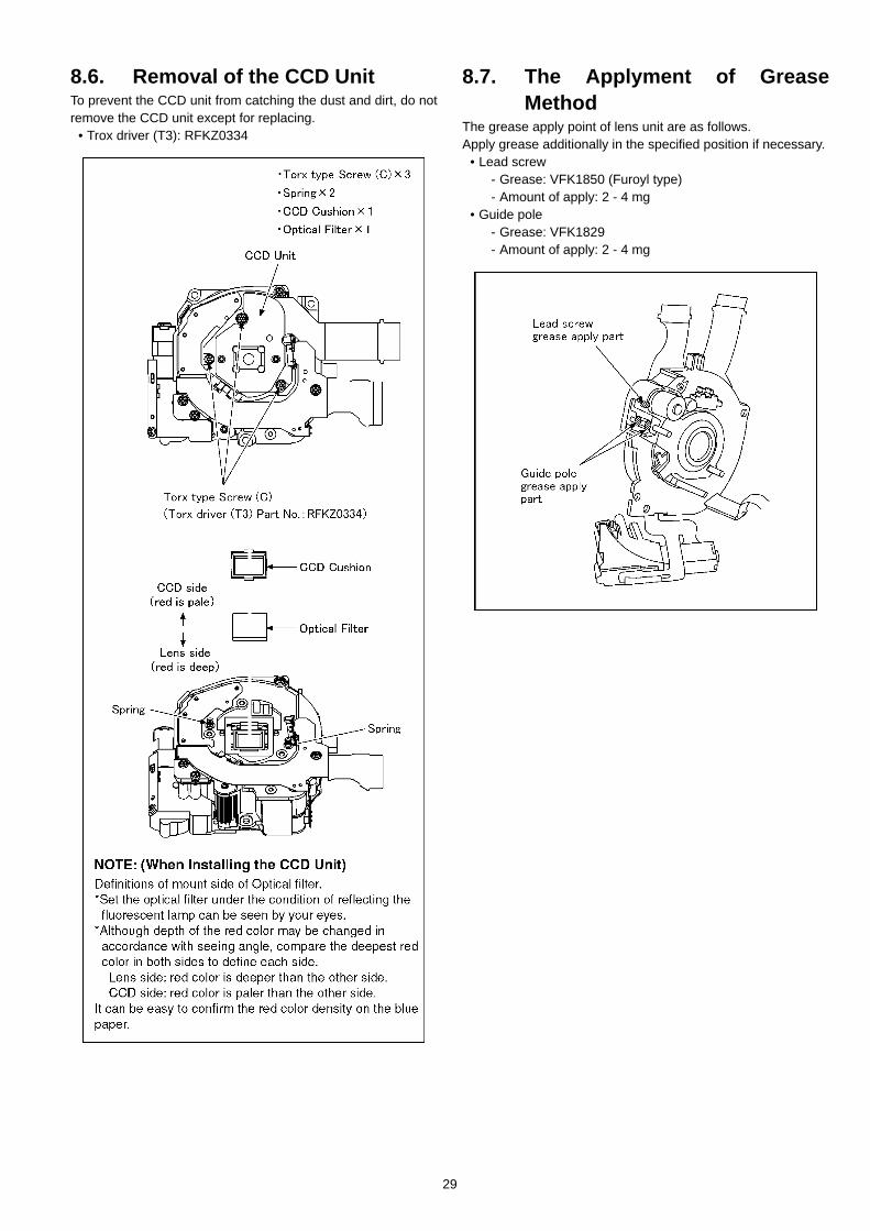
8.6. Removal of the CCD UnitTo prevent the CCD unit from catching the dust and dirt, do notremove the CCD unit except for replacing.
• Trox driver (T3): RFKZ0334
8.7. The Applyment of GreaseMethod
The grease apply point of lens unit are as follows.Apply grease additionally in the specified position if necessary.
• Lead screw- Grease: VFK1850 (Furoyl type)- Amount of apply: 2 - 4 mg
• Guide pole- Grease: VFK1829- Amount of apply: 2 - 4 mg
29
9 Measurements and Adjustments9.1. Matrix Chart for Replaced Part and Necessary AdjustmentThe relation between Replaced part and Necessary Adjustment is shown in the following table.When concerned part is replaced, be sure to achieve the necessary adjustment(s).As for Adjustment condition/procedure, consult the “Adjustment Manual” which is available in Adjustment software.The Adjustment software is available at “TSN Website”, therefore, access to “TSN Website” at “Support Information from NWBG/VDBG-PAVC”.NOTE:
After adjustments have been terminated, make sure to achieve “INITIAL SETTINGS”.
NOTE:*There is no LCD adjustment in this model.*There is no CCD Black scratch compensation adjustment (BKI) in this model.
Replaced Part
Adjustment ItemMain P.C.B. VENUS
(IC6001)Flash-ROM
(IC6002)Lens Part (Excluding
CCD)
CCD Unit
Camera Section
OIS hall element adjustment(OIS)
O O O O
Back focus adjustment(BF)
O O O O
Shutter adjustment(SHT)
O O O O O
ISO sensitivity adjustment(ISO)
O O O O O
AWB adjustmentHigh brightness coloration inspection(WBL)
O O O O O
CCD white scratch compensation(WKI)
O O O O
30

10 Maintenace10.1. Cleaning Lens and LCD PanelDo not touch the surface of lens and LCD Panel with your hand.When cleaning the lens, use air-Blower to blow off the dust.When cleaning the LCD Panel, dampen the lens cleaning paper with lens cleaner, and the gently wipe the their surface.Note:
The Lens Cleaning KIT ; VFK1900BK (Only supplied as 10 set/Box) is available as Service Aid.
31
S-1
S1. About Indication of The Schematic Diagram ............................ S-1S1.1. Important Safety Notice......................................................... S-1
S2. Voltage Chart ........................................................................... S-2S2.1. Flash Top P.C.B. .................................................................... S-2
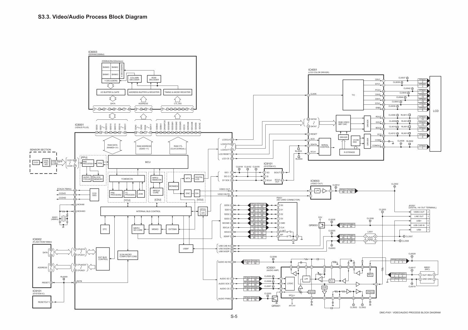
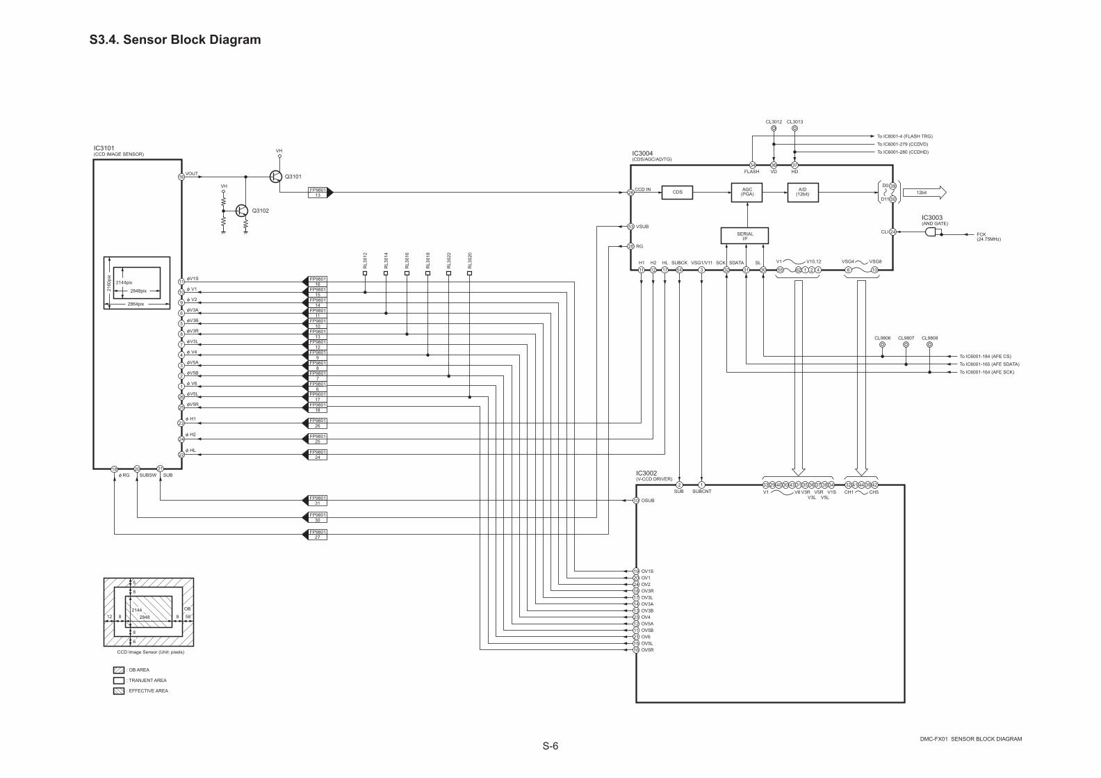
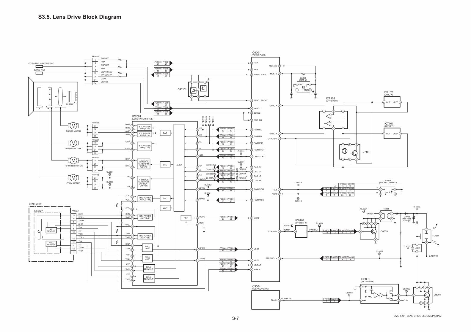
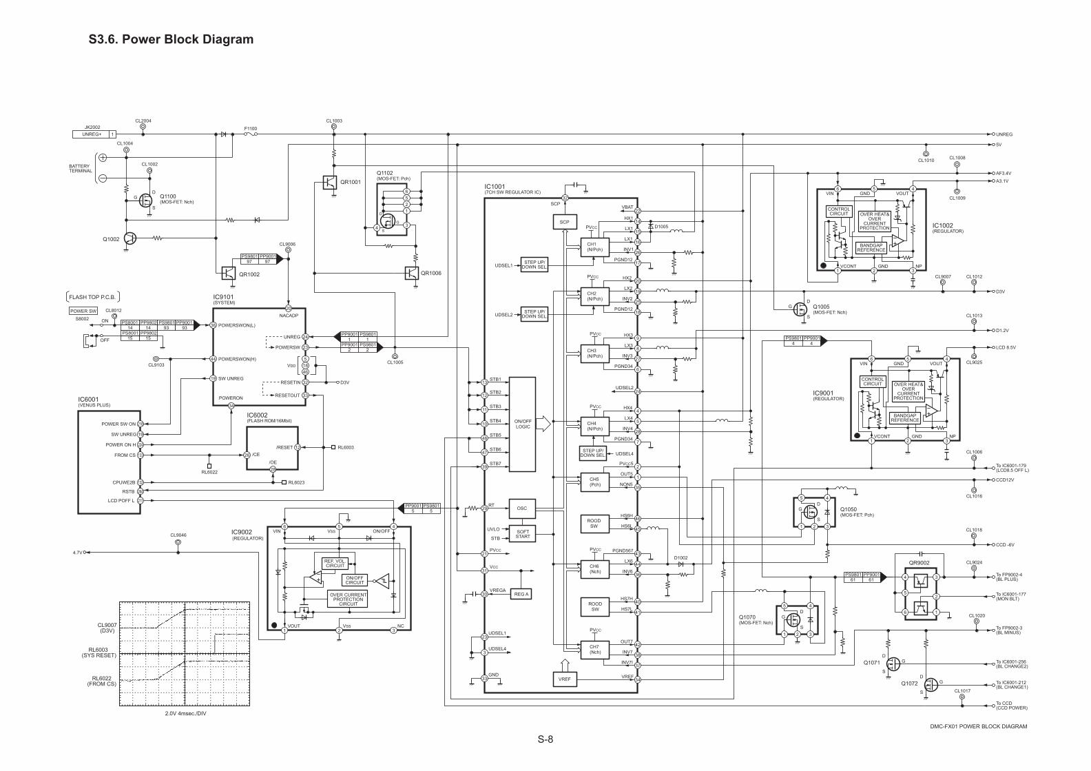
S3. Block Diagram .......................................................................... S-3S3.1. Overall Block Diagram .......................................................... S-3S3.2. System Control Block Diagram ............................................. S-4S3.3. Video/Audio Process Block Diagram .................................... S-5S3.4. Sensor Block Diagram .......................................................... S-6S3.5. Lens Drive Block Diagram..................................................... S-7S3.6. Power Block Diagram............................................................ S-8
S4. Schematic Diagram .................................................................. S-9S4.1. Interconnection Diagram ....................................................... S-9S4.2. Flash Top Schematic Diagram ............................................ S-10S4.3. AF Assist LED Schematic Diagram ..................................... S-11S4.4. CCD Flex Schematic Diagram ............................................ S-11S4.5. Lens Flex Schematic Diagram ............................................ S-12
S5. Print Circuit Board .................................................................. S-13S5.1. Flash Top P.C.B. .................................................................. S-13S5.2. AF Assist LED P.C.B. .......................................................... S-13S5.3. CCD Flex P.C.B. .................................................................. S-14S5.4. Lens Flex P.C.B. .................................................................. S-15
S6. Replacement Parts List .......................................................... S-17
S7. Exploded View ....................................................................... S-23S7.1. Frame and Casing Section.................................................. S-23S7.2. Packing Parts and Accessories Section (1) ........................ S-24S7.3. Packing Parts and Accessories Section (2) ........................ S-25
Table of contents
Service Manual
Digital Camera
DSC0602009CE
Diagrams and ReplacementParts List
Vol. 1Colour(S)...........Silver Type (K)...........Black Type (Except GD) (W)..........White Type (Except PL/EE/GD/GK/GN) (P)...........Pink Type (Only PP/EE/GC/GK/GT/SG) (A)...........Blue Type (Only EE/EF/EG/EGM/GK)
DMC-FX01PP DMC-FX01PL DMC-FX01EBDMC-FX01EEDMC-FX01EF
DMC-FX01EGDMC-FX01EGMDMC-FX01GCDMC-FX01GDDMC-FX01GK
DMC-FX01GNDMC-FX01GT DMC-FX01SG
1.Although reference number of the parts is indicated on the P.C.B. drawing and/orschematic diagrams, it is NOT mounted on the P.C.B. when it is displayed with "$" mark.
2.It is only the "Test Round" and no terminal (Pin) is available on the P.C.B.when the TP (Test Point) indicated as " " mark.
3.The voltage being indicated on the schematic diagram is measured in"Standard-Playback" mode when there is no specify mode is mentioned.
4.Although the voltage and waveform available on here is measured with standard frame,it may be differ from actual measurement due to modification of circuit and so on.
5.The voltage being indicated here may be include observational-error (deviation) due tointernal-resistance and/or reactance of equipment. Therefore, handle the value indicated on here as reference.
6.Use the parts number indicated on the Replacement Parts List .
COMPONENTS IDENTIFIED WITH THE MARK HAVE THE SPECIAL CHARACTERISTICSFOR SAFETY. WHEN REPLACING ANY OF THESE COMPONENTS USE ONLY THE SAME TYPE.
7.Indication on Schematic diagrams:
OFTR FEP
Circuit name being connected.
Name of Signal
This signal is connectedto the FEP schematic diagram
S1. About Indication of The Schematic DiagramS1.1. Important Safety Notice
S-2
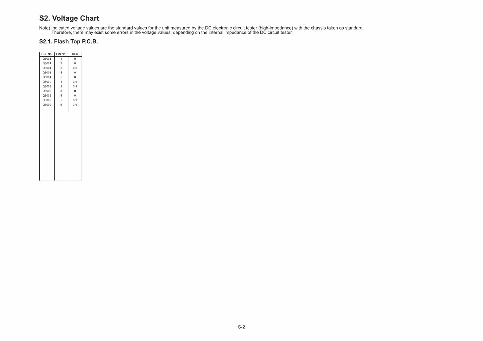
S2. Voltage Chart
S2.1. Flash Top P.C.B.
Note) Indicated voltage values are the standard values for the unit measured by the DC electronic circuit tester (high-impedance) with the chassis taken as standard. Therefore, there may exist some errors in the voltage values, depending on the internal impedance of the DC circuit tester.
REF No. PIN No. REC
Q8001 1 0Q8001 2 0Q8001 3 4.9Q8001 4 0Q8001 5 0Q8009 1 3.9Q8009 2 3.9Q8009 3 0Q8009 4 0Q8009 5 3.9Q8009 6 3.9
S-3
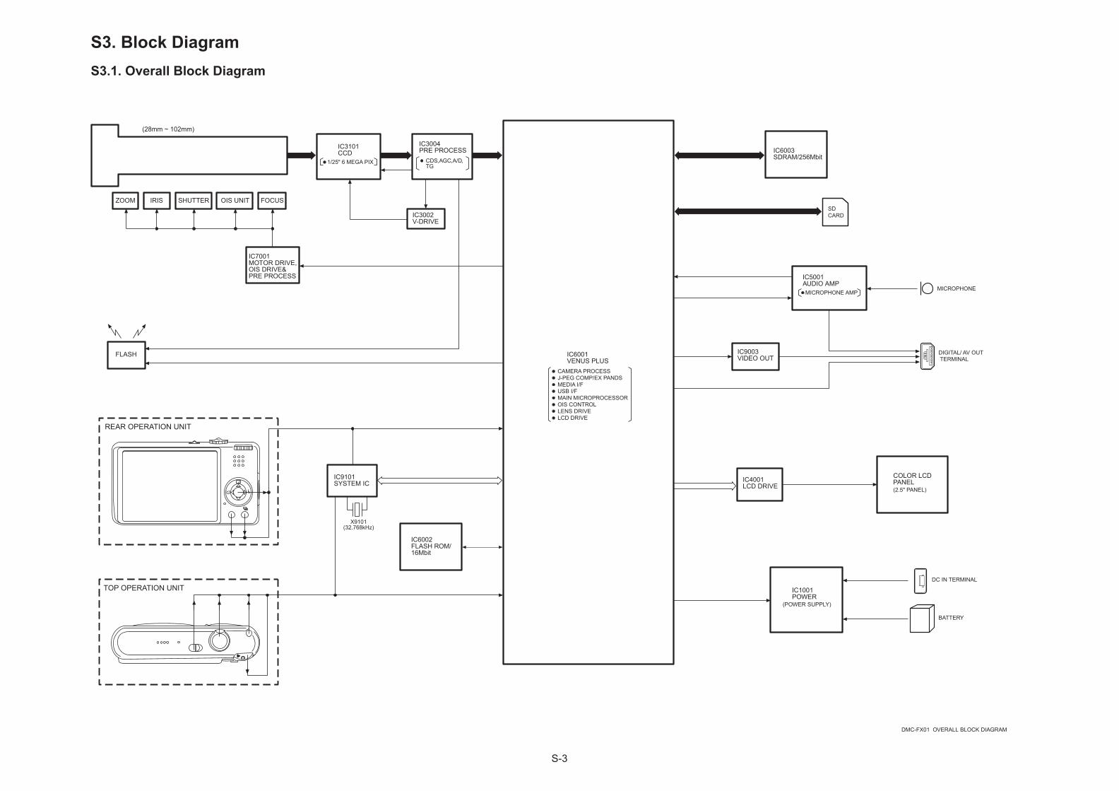
S3. Block DiagramS3.1. Overall Block Diagram
IC3101CCD
IC3004PRE PROCESS
IC3002V-DRIVE
FOCUSIRIS
CDS,AGC,A/D,TG
IC6003SDRAM/256Mbit
SDCARD
IC5001AUDIO AMPMICROPHONE AMP
MICROPHONE
(POWER SUPPLY)
DC IN TERMINAL
BATTERY
REAR OPERATION UNIT
DMC-FX01 OVERALL BLOCK DIAGRAM
IC9003VIDEO OUT
OIS UNIT
IC7001MOTOR DRIVE,OIS DRIVE&PRE PROCESS
IC6001VENUS PLUS
CAMERA PROCESSJ-PEG COMP/EX PANDSMEDIA I/FUSB I/FMAIN MICROPROCESSOR
FLASH
TOP OPERATION UNIT
X9101(32.768kHz)
IC1001POWER
SHUTTER
IC9101SYSTEM IC
IC6002FLASH ROM/16Mbit
ZOOM
OIS CONTROLLENS DRIVELCD DRIVE
1/25" 6 MEGA PIX
DIGITAL/ AV OUTTERMINAL
IC4001LCD DRIVE
COLOR LCDPANEL(2.5" PANEL)
(28mm ~ 102mm)
S-4
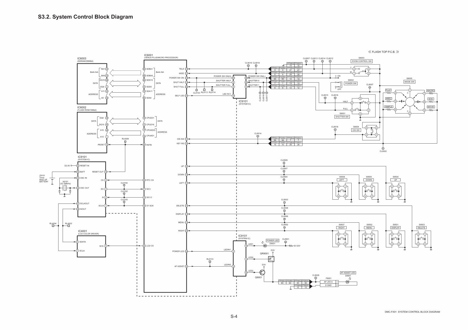
S3.2. System Control Block Diagram
FULL
23
3
24
88
22
26
68
66
85
70
RTC CS
216TELE
WIDE
POWER SW ON
DMC-FX01 SYSTEM CONTROL BLOCK DIAGRAM
IC6001(VENUS PLUS/MICRO PROCESSOR)
SIO I
IC6003(SDRAM/256Mbit)
DATA
ADDRESS
107
86
Bank Adr.
DATA
ADDRESS
45
29
127
108
IC6002(FLASH ROM/16Mbit)
DATA
ADDRESS
DATA
ADDRESS
12 264 RSTB/RESET
4
IC9101(SYSTEM IC)
CS42
209
3SO
2SI
43
X9101(32.768kHz)
Z9101TimerBack UPBATTERY
170
171
SIO O
169 SY SCK
232 LCD CS
217
218
219SHUT HALF
LEFT
176
191
MENU
DELETE
FLASH TOP P.C.B.
229POWER LED
3644
IC9101(SYSTEM IC)
40 BATT
OSC IN
OSC OUT
33RESET OUT
1SCLKSCLKOUT
SIOUT
8
POWER SW ON(H) POWER SW ON(L)
SHUTTER 0SHUTTER HALF
IC9101(SYSTEM IC)
11
14LED1
LEDIN1
32 RESET IND2.9V
2
1
4
3
T
W
ON
OFF1
3
HALF
35
17SHUTTER 1
262SHUT FULL 9SHUTTER FULL
230SELF LED 10LED IN 0
DISPLAY
PP90019
PS800127
PP90018
PS800128
PP900193
PS800114
PP90017
PS800113
PP90016
PS800112
PS800115
3
1
4
2
5
6
2
1
4
3
1
PP900194
PP90011015KEY IN3
2 1
4 3
2 1
4 3
2 1
4 3
2 1
4 3
2 1
4 3
2 1
4 3
2 1
4 3
S9506LEFT
S9507RIGHT
S9505DOWN
S9504UP
S9502MENU
S9503DELETE
S9501DISPLAY
PP900183
PS800130
PS800115
D9901
13
D9501POWER LED
D3V
LED0
BA1
BA0
SDBA1
SDBA0
Bank Adr.
DQ15
DQ0
SDD15
SDD0
A11
A0
SDA11
SDA0
CPUD31
CPUD16
DQ0
DQ15
CPUAD1
CPUAD20A16
A15
CL9104
CL9102
CL9105
220
213
215
210
RIGHT
DOWN
UP 167
CL9014
CL9103 RL9113 RL9114
CL8002
CL8007
CL8013 CL8014 CL8012
CL8015 CL8016
CL8018
RL6009
15LED2
QR9001D3V
D3V
Q9001
S8005
MODE SW
S8003
ZOOM CONTROL SW
S8002
POWER SW
S8001
SHUTTER SW
S8004
OIS SW
AF ASSIST LED
1
48
156
134
6
IC4001(LCD COLOR DRIVER)
SDATA
7 SCLK
5SCS
RL4003RL4004
47
48
PS980183
P8001
AF LED A 1
D GND 2
CL8028
CL9501
CL9502
CL9506
CL9508
CL9503
CL9504
CL9507
CL9509
PS98019
PS98018
PS980193
PS98017
PS98016
CL8007
PS80017
PS800126
2
7
8
9
4 C
C
5
6
PLAY
MOVIE
MACRO
SCN
SIMPLE
AREC
161OIS SW
PP980215
PP980227
PP980228
PP980214
PP980213
PP980212
CL9018CL9019
181AF ASSIST 12LEDIN2
RL9110
PS980194
PP98027
PS980110
PP980226
CL9
015
CL9
016
CL9
017
PP980230
PP980215
S-5
S3.3. Video/Audio Process Block Diagram
I/O BUFFER & GATE
29 62
ROWDECODER
COLUMNDECODER
BANK0 BANK2
BANK1 BANK3
Y DECODERS
XD
EC
OD
ER
S
256Mbit(2Mx32bitx4pcs)
IC6003(SDRAM/256Mbit)
68 66 89
SD
BA
0
SD
BA
1
RAM ADDRESS(SDA0~11)
RAM DATA(RAMD0~31)
CCDCDS,AGCA/D
CDS Signal(12Bit)
266CCD11
CCD0 277
SENSOR SECTION
282CCDSSG
FCK(24.75MHz)
286
CCDHD
CCDVD
MCK48I
DMC-FX01 VIDEO/AUDIO PROCESS BLOCK DAIGRAM
IC6001(VENUS PLUS)
32 433 14 48 59 77 88 22 28 63 69 17 21 70 74
ADDRESS BUFFER & REGISTER TIMING & MODE REGISTER
105 91
SD
D13
SD
D16
55 36
SD
D31
SD
A6
77 70
SD
A11
65 64 62 61 35 60 59 58 56
DR
AM
FCK
SD
DQ
M0
SD
DQ
M1
SD
DQ
M2
SD
DQ
M3
XD
CS
SD
RA
SB
SD
CA
SB
SD
WE
B
SD
CK
E
RAM CTL(CLK/CS/WEetc.)
MCU
279
280
X6001(48MHz)
285
MCK48O
127 CPUD16
CPUD31108
45DATA
29
ADDRESS
IC6002(FLASH ROM/16Mbit)
33
12 264
IC9101(SYSTEM IC)
171SIO I
170SIO O
SDD2
SDD3 241
235SDCMD
236SDCLK
237SDCD
239SDWP
2931
USB SIGDMUSB SIGDP
USBIF
3 5
4
IC9003(VIDEO OUT)
21VIDEO OUT
178VIDEO MUTE
RSTB/RESET
DATA ADDRESS CTL SIG
169SY SCK
242
SDD1 243
SDD0 244
1 4
32
23 24
RESETOUT
SD
D14
SD
D15
8687
JK2001(DIGITAL / AV OUT TERMINAL)
VIDEO OUT 2
USB+ 5
USB- 7
USB CAB IN 8
223USB CAB IN
D3V
QR9003
SD
D1
SD
D0
107S
DA
085 79
SD
A5
3 48
1 47
IC9101(SYSTEM IC)
2
SO
SI
SCLK
SIOUT
SCLKOUT
14 13 12 20 21 22
15
16 4 3 28 25
5
7
8
9
IC5001(AUDIO AMP)
LOGIC
LPF
ABIAS
QR5001
18
ALC
19 23
EVR
7
8
9
1
2
5
10
12
D0
D1
D2
D3
CMD
CLK
C.DET
WP
P6401(SD CARD CONNECTOR)
L2001
12
173
172
187
188
AUDIO AD IN
AUDIO SO
AUDIO SCK
AUDIO CS
AUDIO PWM
LINE OUT 3
PP98023
PS80013
24
REG
M8001(MIC)
PPMPREPROCESS1
BLOCKMEMORY
AUDIOFOCUS
[PPU]
YCMEMCON
PREPROCESS2
YCPROCESS ZOM
[YCU]
MPEGMEMCON
MPEG4CORE
[CDU]
MONMEN
[VOU]
ENC
MTX
D/A
DIGITALLCD
INTERNAL BUS CONTROL
EXT BUSCONTROL
32 Bit MICROCOMPUTER CORE
GPIOU
MEIFUSD CORE MEMIO EXTDMADTC
A/D
LPF
3
PP98021
PS80011
CL8017
CL8019
CL2002
CL2003
CL2008
CL2007
CL2006
CL9104 CL9102 CL9105
CL5006
CL5005
RL6009
17
1
SPBIAS
26SPVCC
2
232LCD CS
48
1
134 CPUAD20
CPUAD1156
255
247
LCDOUT0
LCDOUT7
245LCDCLK 5
6
7
27
26
25
SERIALCONTROL
T/C
60
58
57
55
LCD
ROUT
GOUT
BOUT
FP900110
FP900118
FP900113
SCS
SDATA
SCLK
PCG1
CKH2
CKH1
STH1
IC4001(LCD COLOR DRIVER)
14
22 DATA0
DATA7
62ENB1
FP900116
FP90015
FP900111
12FP9001
RGB VIDEO8BIT DAC
DR
IVE
R
36
34
PCD
COMH9
FP9001
VCOMDAC
DR
IVE
R
DRIVER
FP900119
FP90012
FP900133
STV11
CKV1
R-STRINGS
11CLKIN
CL4012
35COMOUT
9 RESET
LCD RESET 182RL4003
RL4004
PP900186
PS980186
PP900182
PS980182
PP900185
PS980185
PP900187
PS980187
CL9026
PP900165
PS980165
PP900164
PS980164
PP900168
PS980168
PP900167
PS980167
PP900166
PS980166
PP900172
PS980172
PP900163
PS980163
PP900169
PS980169 11
PP900192
PS980192
PP900188
PS980188
PP900189
PS980189
PP900190
PS980190
PP900196
PS980196
CL5009
CL5008
CL5007
FP90011
CL4006 RL9002
RL9010
CL4010 RL9012
CL4008 RL9013
CL4009 RL9014
CL9039
CL9043
CL9044
CL9045
CL9042
CL9037
CL9038
PP98022
PS80012
AF3.4VCL5003 CL5002
1
2
4
3
OUT
GND
REG
GND
CL8029
CL9012
CL6005
CL6003
S-6
S3.4. Sensor Block Diagram
IC3101IC3004
IC3002SUBSW
(CCD IMAGE SENSOR)
VOUT
23
24
212018
(V-CCD DRIVER)
(CDS/AGC/AD/TG)
26
53
54
CDS AGC(PGA)
SERIALI/F
A/D(12bit)
32 31 30
D0 39
OSUB
20
FP980127
FP980130
1
10
FP980131
FP980125
FP980126
FP98016
FP980115
FP980113
50
OV1
SUB
37HD
36VD
34FLASH
SCK SDATA SL
D1112bit
55 62 6 10
33 29 40 30 32 41 44 39CH1 CH5
V1 V10,12 VSG4 VSG8
11 12H1 H2
VSUB
10
2
SUBCK
SUB
2418171413
OV1S
OV3ROV3LOV3A
20 RG
To IC6001-184 (AFE CS)
To IC6001-165 (AFE SDATA)
To IC6001-164 (AFE SCK)
FP98012422
23OV3B
12OV4
43 31 42
V1
V6
H1
H2
HL
RG
FP980114
FP980111
FP980110
FP98019
FP98018
FP98017
9V2
6V3A
5V3B
4V4
3V5A
2V5B
To IC8001-4 (FLASH TRG)
To IC6001-279 (CCDVD)
To IC6001-280 (CCDHD)
CCD IN
CLI 24
1 2 43
1
VSG1/V11
SUBCNT35 38 34
1121
OV5AOV5B
FP98011611
V1S
8
7
FP980113
FP980112
V3R
V3L
FP900117
FP98011825
V5R26
V5L
19
1516
OV2
OV6OV5LOV5R
RL3
012
RL3
014
RL3
016
RL3
018
RL3
022
RL3
020
17HL
V1 V636 37
V3RV3L
V5RV5L
V1S
IC3003(AND GATE)
FCK(24.75MHz)
21442848 88 58
8
12
5
6
8
OB
CCD Image Sensor (Unit: pixels)
: OB AREA
: TRANJENT AREA
: EFFECTIVE AREA
DMC-FX01 SENSOR BLOCK DIAGRAM
CL3012 CL3013
Q3101
VH
VH
Q3102
2144pix
2848pix
2864pix
2160
pix
16
CL9806 CL9807 CL9808
S-7
S3.5. Lens Drive Block Diagram
YPWM
FILTERCCD
MFOCUS MOTOR
M
IRIS(ND) MOTOR
MZOOM MOTOR
ZOOM ENC
36
39
38
19
20
198
199
201
DAC CK
DAC DI
DAC LD
18
17
16
58
4
6
CK
DI
LD
IC7001(LENS MOTOR DRIVE)
29
30
DMC-FX01 LENS DRIVE BLOCK DIAGRAM
37
M
SHUTTER MOTOR
CO BARREL & FOCUS ENC
6GYRO X
IC6001(VENUS PLUS)
20329 PWM SHUT
H-BRIDGECONSTANTCURRENTDRIVER
ED
34
32
41
39
27
26
25
22
MN
MP
202 PWM IRISEC
205 PWM FBEB
204 PWM FAEA
HALLSENSOR
HALLSENSOR
OIS UNIT
LENS UNIT
DMP
DMN
YMP
YMN
XMP
XMN
52
60
1YPOS
XPOS2
YPOS
XPOS
Q7101
3 1
64 5
28
27
25
26
23
24
FP9802
FP9802
FP9802
FP9802
7
9BTL POWERAMP(B ch)
BMP
BMN
13
10
CMP
CMN
55
28
61
62
44
193 PWM XOIS
REFO
FP9802XDR-
XDR+
XHO+
XHO-
YDR-
YDR+
YHO+
YHO-
4
5
321
67
8 Q8001
34
IC3004(CDS/AGC/AD/TG)
FLASHFLASH TRG PP9802
5PS8001
5
6 57
2 31
4GYRO Y
175GYRO SW
4 OUT VREF 1
4 OUT VREF 1AMP
AMN
XINN
XINP
2
IC7101(GYRO Y)
IC7102(GYRO X)
21
22
CL9804
CL9803
CL8004
IC7103(GYRO AMP)
DAC
LOGIC
H-BRIDGECONSTANTCURRENTDRIVER
21SYSCK
DAC
DAC36
37
38
35
XFIL
YDA
XDA
YFIL
HALLAMP
ADC
51
50YINN
YINPHALLAMP
15
16
9
7
8
10
17
18
12
14
13
11
XV+
XV-
YV+
YV-
HALLELEMENT
3XVN
XVP64
HALLELEMENT
45YVN
YVP48
192 PWM YOIS
9
10
YDR AD
XDR AD
RL7002
BTL POWERAMP(A ch)
BTL POWERAMP(C ch)
BTL POWERAMP(X/Y ch)
BTL POWERAMP(X ch)
BTL POWERAMP(Y ch)
14XPWM
15
RL7001
REF 3 MREF43
REFI
RL7
008
RL7
009
RL7
010
RL7
011
23130 LEN STDBYSTB
IC8001(ST TRG AMP)
CL9811
CL9810
CL9809
32
35
31
34
5
3
2ZENC1 LED
ZENC2 LED
ZENC1
ZENC2
QR7102
654
3 12
FHP
ZHP LED
ZHP
ZENC LEDCNT228
261
189
ZENC1
ZENC2
227 FZHP LEDCNT
260 FHP6
FP9802FHP LED
S8003(ZOOM CONTROL)
TELE
217
216
WIDE PP980228
PS800128
PP980227
PS800127
PP980215
PS800115
2
1
4
3
T
W
2
1
3
4
T8001
2
1
FLASH
C8003(For FlashCharge)
1
4
256
3 Q80093938
IC9101(SYSTEM IC)
PWM IN PWMOUT
PP900111
PS980111
PP98026
PS80016
13STB CHG LV
STB PWM 185
1
2
3 L8001TL8001
TL8003
CL8009
UNREG
RL9104RL9103
4
5
3
2
5.0V
PP900157
PS980157
PP900156
PS980156
195 ENC INB
PP900158
PS980158
PP900159
PS980159
PP900147
PS980147
PP900148
PS980148 197 ZHP
PP900139
PS980139
PP900138
PS980138
PP900137
PS980137
PP900136
PS980136
PP900179
PS980179
PP900152
PS980152
PP900153
PS980153
PP900154
PS980154
PP900134
PS980134
PP900135
PS980135
PP900144
PS980144
PP900143
PS980143
PP900142
PS980142
PP900145
PS980145
PP900146
PS980146
245 LCDCLK
CL9051
CL9031
CL9030
CL9029
PP900132
PS980132
CL9813 CL9036
285
286
MCK48I
MCK48O
X6001(48MHz)
4
1 2
3GND
GND
PS80018
PS80019
PP90018
PP90019
CL9019
CL9018
PP900112
PS980112
PP98029
PS80019
CL8005
TL8002
CL8021
S-8
S3.6. Power Block Diagram
IC1001(7CH SW REGULATOR IC)
INV1
LX115
32SCP
26
LX1
17
13STB1
12
11
29RT
31
21
VCC
PVCC
D3V
218
IC6001(VENUS PLUS)
224
44
36
IC9101(SYSTEM)
20
23
POWERSWON(L)
POWERSWON(H)
POWERSW
NACADP
POWERON
POWER SW ON
POWER ON H
34
12
28
IC6002(FLASH ROM/16Mbit)
/RESET
/OE
33RESETOUT
264RSTB
132 RL6023CPUWE2B
19 SW UNREG
19SW UNREG
16CH1(N/Pch)
14
22HX1
VBAT
PGND12
HX220
25
LX2
18
19CH2(N/Pch) INV2
27
LX3
6
8CH3(N/Pch) INV3
LX4
7
5CH4(N/Pch)
4HX4
PGND34
NON5
PVCC52
OUT51CH5
(Pch)
INV6
PGND56743
36
LX644CH6
(Nch)
INV738
OUT742CH7
(Nch)
INV7I
34
SCP
10 ON/OFFLOGIC
OSC
DMC-FX01 POWER BLOCK DIAGRAM
UNREG
CL9006
RL6003
51846
VDD
24
32RESETIN D3V
UNREG
STB2
STB3
STB4
5V
AF3.4V
CL1010
D1.2V
CCD12V
1 2 3
45D
S
G
1 2 3
45D
S
GQ1070(MOS-FET: Nch)
CCD -6V
To FP9002-4(BL PLUS)
VREF
CL1012
CL1013
CL1016
CL1018
CL9024
CL9007(D3V)
RL6003(SYS RESET)
RL6022(FROM CS)
2.0V 4msec./DIV
Q1050(MOS-FET: Pch)
PGND12
PGND34
HX39
INV428
PVCC
PVCC
PVCC
PVCC
HS6L45
HS6H46ROOD
SW
HS7L
HS7H40ROOD
SW
PVCC
PVCC
VREF
48
47
STB5
STB6
39STB7
23UDSEL1
24UDSEL2
3UDSEL4
33GND
REG A30VREGA
QR1002
Q1005(MOS-FET: Nch)
D1005
CL1008
To CCD(CCD POWER)
D1002
D
S
G To IC6001-256(BL CHANGE2)
CL1020
To FP9002-3(BL MINUS)
Q1071
D
S
G
SOFTSTART
UVLO
STB
STEP UP/DOWN SEL.UDSEL1
STEP UP/DOWN SEL.UDSEL2
STEP UP/DOWN SEL. UDSEL4
BATTERYTERMINAL
JK2002UNREG+ 1
Q1002
CL1002
CL1004
CL2004
D
S
G
F1100
CL1003
D
S
G
1
34
Q1102(MOS-FET: Pch)
256
PP90011
PS98011
PP90012
PS98012
PS800115
PP900193
ON
OFF
POWER SW
FLASH TOP P.C.B.
PS800114
CL8012
PP980215
PP980214
PS980197
PP900197
QR1006
QR1001
1 2
6
OVER HEAT&OVER
CURRENTPROTECTION
CONTROLCIRCUIT
BANDGAPREFERENCE
3
4VOUTVIN
VCONT GND NP
5GND
IC1002(REGULATOR)
A3.1V
CL1009
CL1005
IC9001(REGULATOR)
1 2
6
OVER HEAT&OVER
CURRENTPROTECTION
CONTROLCIRCUIT
BANDGAPREFERENCE
3
4VOUTVIN
VCONT GND NP
5GND
PS98014
PP90014
LCD 8.5V
CL9025
To IC6001-179(LCD8.5 OFF L)
PS980161
PP900161
6
5
4 3
1
2
QR9002
To IC6001-177(MON BLT)
D
S
GQ1072 To IC6001-212(BL CHANGE1)
CL1017
35
41
37
CL1006
1 2
6
3
4ON/OFFVIN
VOUT VSS NC
5VSSIC9002
(REGULATOR)
OVER CURRENTPROTECTION
CIRCUIT
REF. VOL.CIRCUIT
ON/OFFCIRCUIT
211LCD POFF L
4.7V
CL9046
PS98015
PP90015
Q1100(MOS-FET: Nch)
PS980193
S8002
CL9103
133FROM CS 26 /CE
RL6022
CL9007
S-9
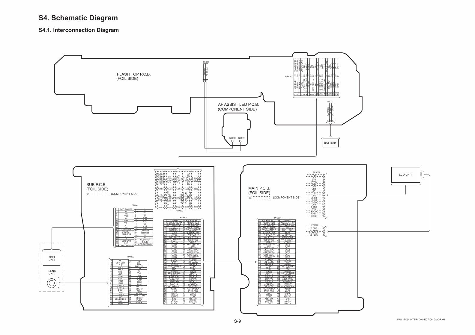
S4. Schematic DiagramS4.1. Interconnection Diagram
DMC-FX01 INTERCONNECTION DIAGRAM
SUB P.C.B.(FOIL SIDE)
: (COMPONENT SIDE)
51 D GND52 DAC CK53 DAC DI54 DAC LD55 D GND56 ZENC257 ZENC158 FZHP LED59 ZENC LED60 BL CHANGE261 BL VDD62 BL MINUS63 SDCD64 SDDAT165 SDDAT066 SDCMD67 SDDAT368 SDDAT269 SDWP70 A3R1V71 D GND72 SDCLK73 D GND74 AFE SCK75 AFE SDATA76 AFE CS77 CCDHD78 CCDVD79 LENS STDBY80 CABLE DET81 VIDEO GND82 VIDEO OUT83 AF LED A84 USB GND85 USB-86 USB CAB IN87 USB+88 AUDIO SO89 AUDIO SCK90 AUDIO CS91 A GND92 AUDIO AD IN93 POWER ON L94 OIS SW95 BATT THERMO96 AUDIO PWM97 ACADP IN98 UNREG GND99 FRAME GND100 BACKUP BATT1 UNREG
2 POWER CTL SW3 LCD8R5 OFF L4 LCD 8R5V SRC5 5V6 SHUTTER 17 SHUTTER 08 WIDE9 TELE
10 MODE DIAL11 STB CHG LV12 STB PWM OUT13 CCD1114 CCD1015 CCD916 CCD817 CCD718 CCD619 CCD520 CCD421 CCD322 CCD223 CCD124 CCD025 D GND26 FCK27 D GND28 CCD THERMO29 D3V30 D3V31 D GND32 LEN SYSCLK33 D GND34 PWM XOIS35 PWM YOIS36 PWM SHUT37 PWM IRIS38 PWM FB39 PWM FA40 BL CHANGE141 A GND42 YPOS43 XPOS44 MREF45 XDR AD46 YDR AD47 FHP48 ZHP49 D1R2V50 D1R2V
PS9801 PP90011 UNREG2 POWER CTL SW3 LCD8R5 OFF L4 LCD 8R5V SRC5 5V6 SHUTTER 17 SHUTTER 08 WIDE9 TELE
10 MODE DIAL11 STB CHG LV12 STB PWM OUT13 CCD1114 CCD1015 CCD916 CCD817 CCD718 CCD619 CCD520 CCD421 CCD322 CCD223 CCD124 CCD025 D GND26 FCK27 D GND28 CCD THERMO29 D3V30 D3V31 D GND32 LEN SYSCLK33 D GND34 PWM XOIS35 PWM YOIS36 PWM SHUT37 PWM IRIS38 PWM FB39 PWM FA40 BL CHANGE141 A GND42 YPOS43 XPOS44 MREF45 XDR AD46 YDR AD47 FHP48 ZHP49 D1R2V50 D1R2V51 D GND
52 DAC CK53 DAC DI54 DAC LD55 D GND56 ZENC257 ZENC158 FZHP LED59 ZENC LED60 BL CHANGE261 BL VDD62 BL MINUS63 SDCD64 SDDAT165 SDDAT066 SDCMD67 SDDAT368 SDDAT269 SDWP70 A3R1V71 D GND72 SDCLK73 D GND74 AFE SCK75 AFE SDATA76 AFE CS77 CCDHD78 CCDVD79 LENS STDBY80 CABLE DET81 VIDEO GND82 VIDEO OUT83 AF LED A84 USB GND85 USB-86 USB CAB IN87 USB+88 AUDIO SO89 AUDIO SCK90 AUDIO CS91 A GND92 AUDIO AD IN93 POWER ON L94 OIS SW95 BATT THERMO96 AUDIO PWM97 ACADP IN98 UNREG GND99 FRAME GND100 BACKUP BATT
FP9801
33 323129 2827 26
30CCD GND
CCD POWER SE CCD THERMOSUB BSUBCCD GNDR H125
23 24
21 2022
H2CCD GND HL
GUARD2CCDOUT GUARD119 18CCD GND V5R17 V5L 16 V1S15 V1 14 V213 V3R 12 V3L11 V3A 10 V3B9 V4 8 V5A7 V5B 6 V65 NC 4 VH3 NC 2 VL1 CCD POWER
FP9802
1 235 67 8
4FHP
NC ZHPZHP LED D3VFHP LEDXHO- XV+9
11 10
13 1412
XHO+YHO- XV-
YV+YHO+ YV-15 16XDR- XDR+17 YDR- 18 YDR+19 IRIS1 20 IRIS121 IRIS2 22 IRIS223 SHUT1 24 SHUT125 SHUT2 26 SHUT227 DCM- 28 DCM-29 DCM+ 30 DCM+31 ZENC1 32 ZENC1 LED33 D3V 34 ZENC235 ZENC2 LED 36 FMBP37 FMBN 38 FMAN39 FMAP
CCDUNIT
LENSUNIT
FP9001COMCKVSTV
VVDDENBCSVVBB
16151413121110987654321
SCDSDDSG
LCD BLCD RLCD GCSH
D GND
CKH2
STHHVDDCKH1
171819
LCD UNIT
FP9002D GND
BL RANKBL MINUSBL PLUS 4
321
MAIN P.C.B.(FOIL SIDE)
: (COMPONENT SIDE)
PS8001
1M
ICG
ND
2M
ICIN
3M
ICR
EG
4A
GN
D5
FLA
SH
TRG
6S
TBP
WM
OU
T7
OIS
SW
8N
C9
STB
CH
GLV
10N
C11
NC
12S
HU
TTE
R1
13S
HU
TTE
R0
14P
OW
ER
ON
L15
DG
ND
16TH
ER
MO
17B
ATT-
18B
ATT-
19B
ATT-
20B
ATT-
21B
ATT+
22B
ATT+
23B
ATT+
24B
ATT+
25N
C26
MO
DE
DIA
L27
TELE
28W
IDE
295V
30A
FLE
DA
31S
P+
32S
P-
33N
C34
UN
RE
G35
UN
RE
G36
NC
37U
NR
EG
GN
D38
UN
RE
GG
ND
39FR
AM
EG
ND
40FR
AM
EG
ND
P8002
1B
ATTE
RY
+2
BAT
TER
Y-3
THE
RM
O
MIC
GN
D1
MIC
IN2
MIC
RE
G3
AG
ND
4FL
AS
HTR
G5
STB
PW
MO
UT
6O
ISS
W7 8 9 10 11 12 13 14 15 16 17 18
25262728293031323334353637383940FR
AM
EG
ND
FRA
ME
GN
DU
NR
EG
GN
DU
NR
EG
GN
DN
CU
NR
EG
UN
RE
GN
CS
PN
EG
SP
PO
SA
FLE
DA
5VW
IDE
TELE
MO
DE
DIA
L
BAT
+N
C
NC
STB
CH
GLV
NC
NC
SH
UTT
ER
1S
HU
TTE
R0
PO
WE
RO
ND
GN
D
BAT
+B
AT-
PP9802
BAT
TTH
ER
MO
BAT
-B
AT-
19 20
24 23 22 21B
AT-
BAT
+B
AT+
BATTERY
P8001
1A
FLE
DA
2D
GN
D
AF ASSIST LED P.C.B.
TL9902 TL9901
FLASH TOP P.C.B.(FOIL SIDE)
(COMPONENT SIDE)
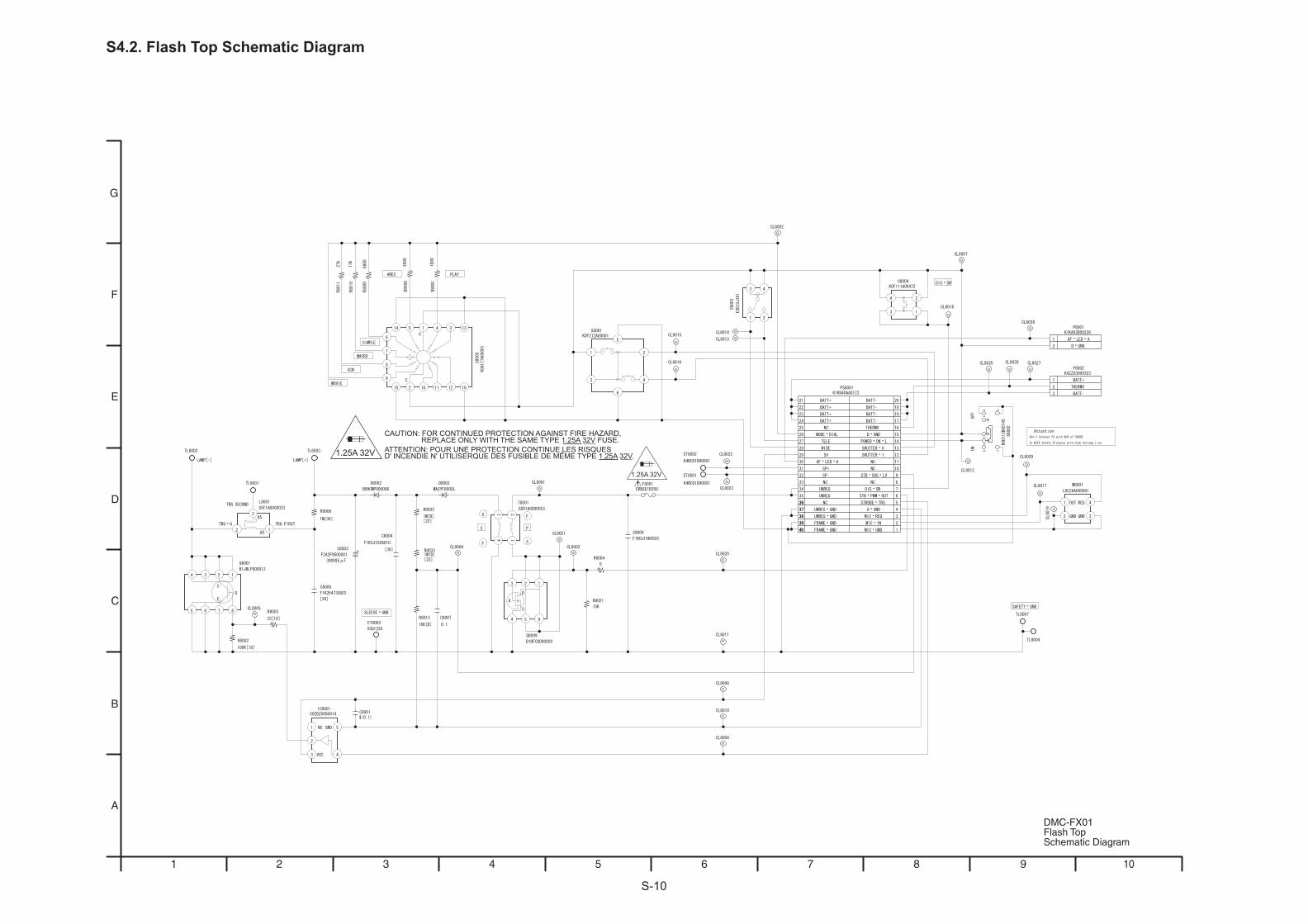
S-10
S4.2. Flash Top Schematic Diagram
1.25A 32V
1.25A 32V
CAUTION: FOR CONTINUED PROTECTION AGAINST FIRE HAZARD, REPLACE ONLY WITH THE SAME TYPE 1.25A 32V FUSE.ATTENTION: POUR UNE PROTECTION CONTINUE LES RISQUESD' INCENDIE N' UTILISERQUE DES FUSIBLE DE MEME TYPE 1.25A 32V.
10987654321
F
E
D
C
B
A
G
DMC-FX01Flash TopSchematic Diagram
S-11
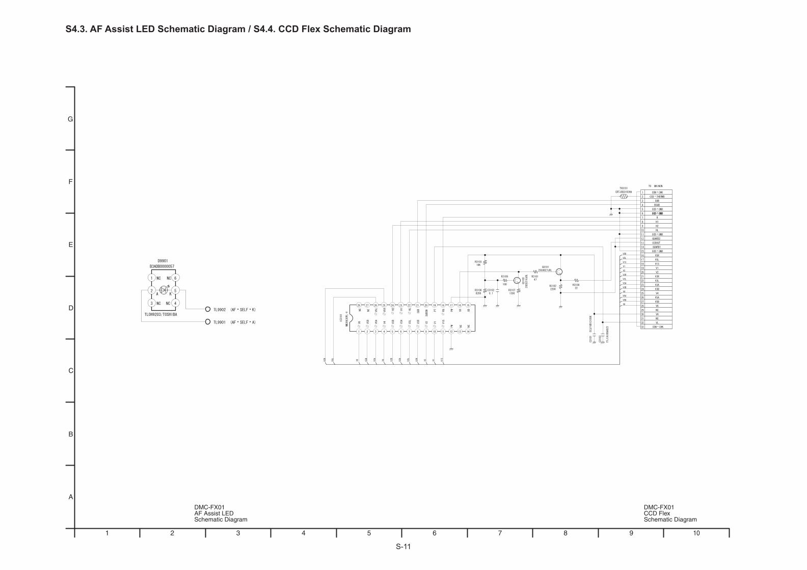
S4.3. AF Assist LED Schematic Diagram / S4.4. CCD Flex Schematic Diagram
10987654321
F
E
D
C
B
A
G
DMC-FX01CCD FlexSchematic Diagram
DMC-FX01AF Assist LEDSchematic Diagram
S-12
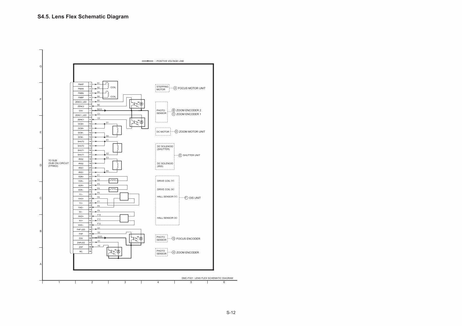
S4.5. Lens Flex Schematic Diagram
A
B
C
D
E
F
G
654321
5
6
7
8
13
14
15
24
25
28
29
26
27
21
22
36
37
38
39
4
3
2
1
PHOTOSENSOR FOCUS ENCODER
DC MOTOR ZOOM MOTOR UNIT
DRIVE COIL (X)
DRIVE COIL (Y)
HALL SENSOR (Y)
HALL SENSOR (X)
OIS UNIT
STEPPINGMOTOR FOCUS MOTOR UNIT
DC SOLENOID(IRIS)
A1
A2
A3
F9
F10
D2
G
D
A
F
10
11
9
12
16
17
18
19
20
23
30
31
32
33
34
35
A4
COIL
COIL
D1
F11
F12
F1
F2
F3
F4
DC SOLENOID(SHUTTER)
SHUTTER UNITE
POSITIVE VOLTAGE LINE
DMC-FX01 LENS FLEX SCHEMATIC DIAGRAM
TO SUB (SUB CN) CIRCUIT(FP9802)
FMAP
FMAN
FMBN
FMBP
ZENC2_LED
ZENC2
D3V
ZENC1_LED
ZENC1
DCM+
DCM+
DCM-
DCM-
SHUT2
SHUT2
SHUT1
SHUT1
IRIS2
IRIS2
IRIS1
IRIS1
YDR+
YDR-
XDR+
XDR-
YV-
YHO+
YV+
YHO-
XV-
XHO+
XV+
XHO-
FHP LED
FHP
D3V
ZHPLED
ZHP
NC
B/C3
B2
B1
C2
C1
E2
E1
E4
E3
F5
F6
F7
F8
G1
G2
G/H3
H1
H2
PHOTOSENSOR ZOOM ENCODERH
PHOTOSENSOR
ZOOM ENCODER 2B
ZOOM ENCODER 1C
S-13
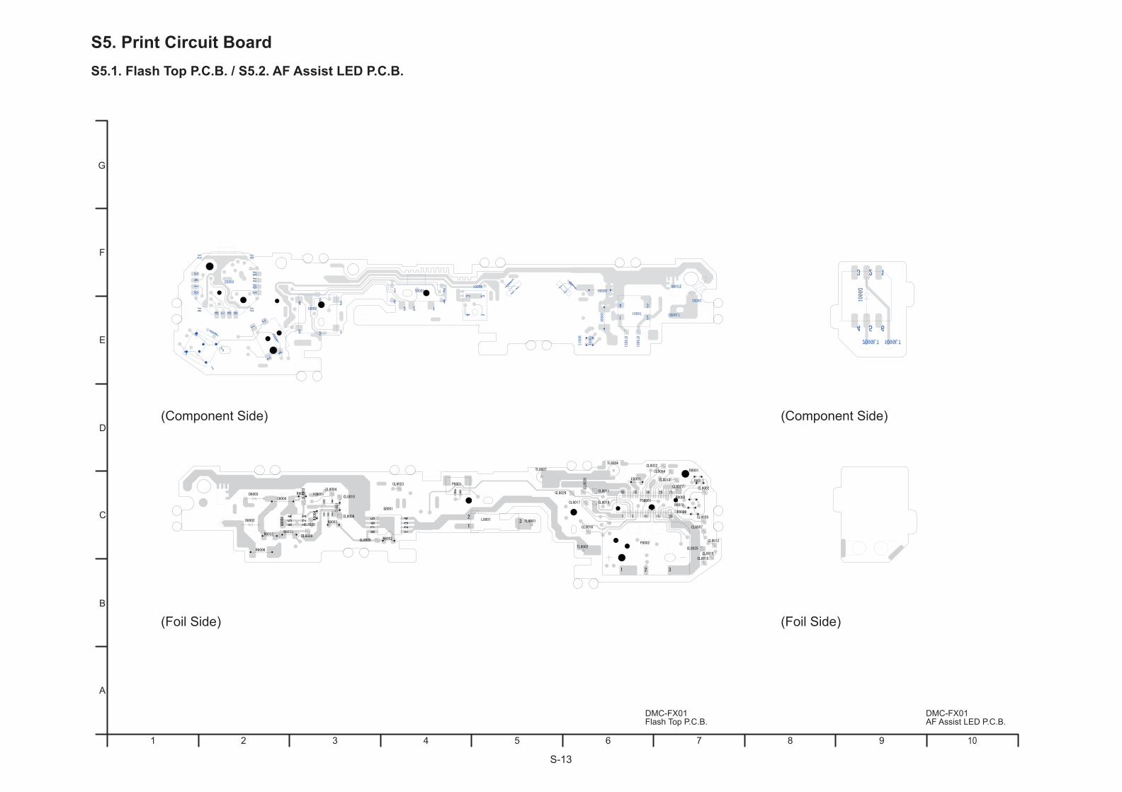
S5. Print Circuit BoardS5.1. Flash Top P.C.B. / S5.2. AF Assist LED P.C.B.
10987654321
F
E
D
C
B
A
G
(Foil Side) (Foil Side)
(Component Side) (Component Side)
DMC-FX01AF Assist LED P.C.B.
DMC-FX01Flash Top P.C.B.
S-14
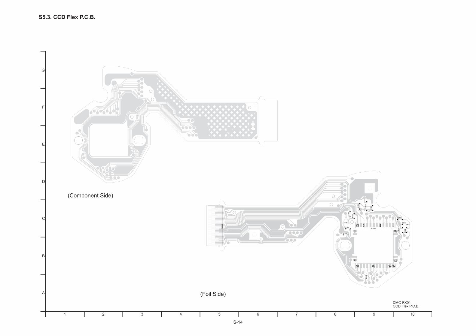
S5.3. CCD Flex P.C.B.
10987654321
F
E
D
C
B
A
G
(Foil Side)
(Component Side)
DMC-FX01CCD Flex P.C.B.
S-15
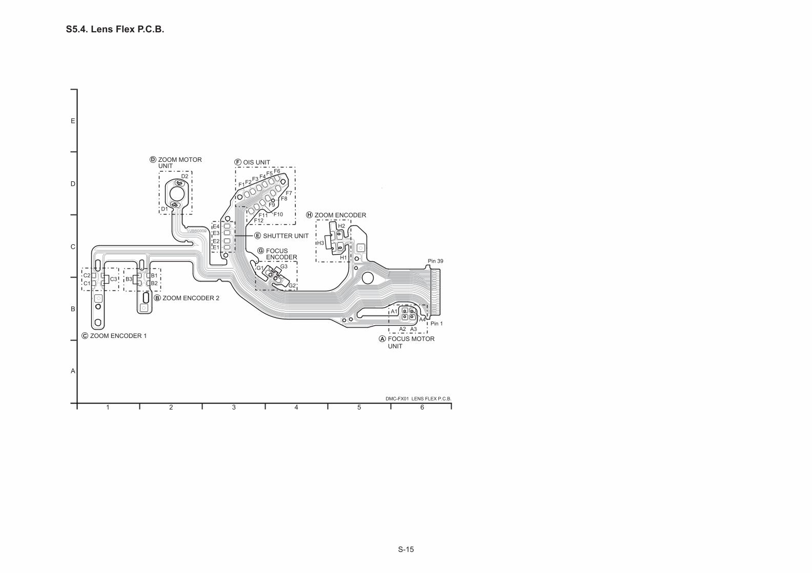
S5.4. Lens Flex P.C.B.
1 2 3 4 5 6
A
B
C
D
E
DMC-FX01 LENS FLEX P.C.B.
Pin 39
Pin 1
FOCUS MOTOR UNIT
A2
A
B
B3
ZOOM ENCODER 2
B1B2
C
C3
ZOOM ENCODER 1
C1C2
ZOOM MOTOR UNIT
D1
D
D2
A3
A1A4
OIS UNITF
F4F1
F7
F10
F6F5F3F2
F8F9
F11F12
E4E3E2E1
SHUTTER UNITE
G3G1
G2
FOCUSENCODER
GH3
H1
H2
ZOOM ENCODERH

S-16
E.S.D. standards for Electrostatically Sensitive Devices, refer to “PREVENTION OF ELECTROSTATIC DISCHARGE (ESD) TO ELECTROSTATICALLY SENSITIVE (ES) DEVICES” section.
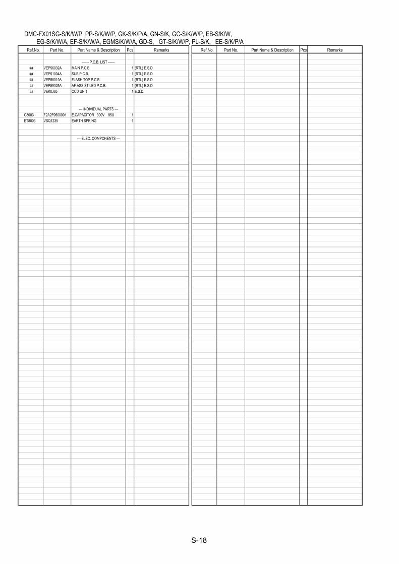
1.* Be sure to make your orders of replacement parts according to this list.2. IMPORTANT SAFETY NOTICE Components identified with the mark have the special characteristics for safety. When replacing any of these components, use only the same type.3. Unless otherwise specified, All resistors are in OHMS, K=1,000 OHMS. All capacitors are in MICRO-FARADS (uf), P=uuF.4. The marking (RTL) indicates the retention time is limited for this item. After the discontinuation
of this assembly in production, it will no longer be available.
Note:
S6. Replacement Parts List
S-17
DMC-FX01SG-S/K/W/P, PP-S/K/W/P, GK-S/K/P/A, GN-S/K, GC-S/K/W/P, EB-S/K/W, EG-S/K/W/A, EF-S/K/W/A, EGMS/K/W/A, GD-S, GT-S/K/W/P, PL-S/K, EE-S/K/P/A
Ref.No. Part No. Part Name & Description Pcs Remarks Ref.No. Part No. Part Name & Description Pcs Remarks ------ P.C.B. LIST ------ ## VEP56032A MAIN P.C.B. 1 (RTL) E.S.D. ## VEP51004A SUB P.C.B. 1 (RTL) E.S.D. ## VEP58019A FLASH TOP P.C.B. 1 (RTL) E.S.D. ## VEP59025A AF ASSIST LED P.C.B. 1 (RTL) E.S.D. ## VEK0J65 CCD UNIT 1 E.S.D. --- INDIVIDUAL PARTS --- C8003 F2A2F9500001 E.CAPACITOR 300V 95U 1 ET8003 VSQ1235 EARTH SPRING 1 --- ELEC. COMPONENTS ---
S-18
DMC-FX01SG-S/K/W/P, PP-S/K/W/P, GK-S/K/P/A, GN-S/K, GC-S/K/W/P, EB-S/K/W, EG-S/K/W/A, EF-S/K/W/A, EGMS/K/W/A, GD-S, GT-S/K/W/P, PL-S/K, EE-S/K/P/A
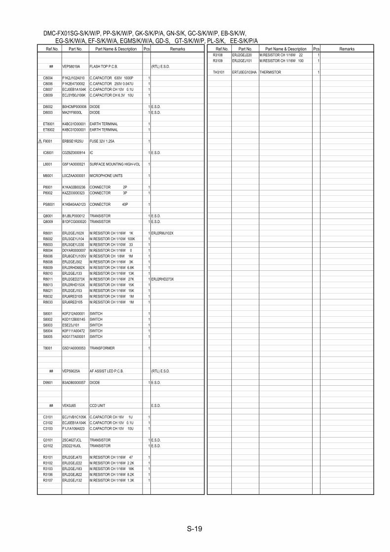
Ref.No. Part No. Part Name & Description Pcs Remarks Ref.No. Part No. Part Name & Description Pcs Remarks R3108 ERJ2GEJ220 M.RESISTOR CH 1/16W 22 1 R3109 ERJ2GEJ101 M.RESISTOR CH 1/16W 100 1 ## VEP58019A FLASH TOP P.C.B. (RTL) E.S.D. TH3101 ERTJ0EG103HA THERMISTOR 1 C8004 F1K2J102A010 C.CAPACITOR 630V 1000P 1 C8006 F1K2E4730002 C.CAPACITOR 250V 0.047U 1 C8007 ECJ0EB1A104K C.CAPACITOR CH 10V 0.1U 1 C8009 ECJ3YB0J106K C.CAPACITOR CH 6.3V 10U 1 D8002 B0HCMP000006 DIODE 1 E.S.D. D8003 MA2YF8000L DIODE 1 E.S.D. ET8001 K4BC01D00001 EARTH TERMINAL 1 ET8002 K4BC01D00001 EARTH TERMINAL 1 F8001 ERBSE1R25U FUSE 32V 1.25A 1 IC8001 C0ZBZ0000914 IC 1 E.S.D. L8001 G5F1A0000021 SURFACE MOUNTING HIGH-VOL 1 M8001 L0CZAA000001 MICROPHONE UNITS 1 P8001 K1KA02B00236 CONNECTOR 2P 1 P8002 K4ZZ03000323 CONNECTOR 3P 1 PS8001 K1KB40AA0123 CONNECTOR 40P 1 Q8001 B1JBLP000012 TRANSISTOR 1 E.S.D. Q8009 B1DFCG000020 TRANSISTOR 1 E.S.D. R8001 ERJ2GEJ102X M.RESISTOR CH 1/16W 1K 1 ERJ2RMJ102X R8002 ERJ3GEYJ104 M.RESISTOR CH 1/10W 100K 1 R8003 ERJ3GEYJ330 M.RESISTOR CH 1/10W 33 1 R8004 D0YAR0000007 M.RESISTOR CH 1/16W 0 1 R8006 ERJ8GEYJ105V M.RESISTOR CH 1/8W 1M 1 R8008 ERJ2GEJ302 M.RESISTOR CH 1/16W 3K 1 R8009 ERJ2RHD682X M.RESISTOR CH 1/16W 6.8K 1 R8010 ERJ2GEJ133 M.RESISTOR CH 1/16W 13K 1 R8011 ERJ2GED273X M.RESISTOR CH 1/16W 27K 1 ERJ2RHD273X R8013 ERJ2RHD153X M.RESISTOR CH 1/16W 15K 1 R8021 ERJ2GEJ153 M.RESISTOR CH 1/16W 15K 1 R8032 ERJ6RED105 M.RESISTOR CH 1/16W 1M 1 R8033 ERJ6RED105 M.RESISTOR CH 1/16W 1M 1 S8001 K0F212A00001 SWITCH 1 S8002 K0D112B00145 SWITCH 1 S8003 ESE23J101 SWITCH 1 S8004 K0F111A00472 SWITCH 1 S8005 K0G177A00001 SWITCH 1 T8001 G5D1A0000053 TRANSFORMER 1 ## VEP59025A AF ASSIST LED P.C.B. (RTL) E.S.D. D9901 B3ADB0000057 DIODE 1 E.S.D. ## VEK0J65 CCD UNIT E.S.D. C3101 ECJ1VB1C105K C.CAPACITOR CH 16V 1U 1 C3102 ECJ0EB1A104K C.CAPACITOR CH 10V 0.1U 1 C3103 F1J1A106A023 C.CAPACITOR CH 10V 10U 1 Q3101 2SC4627JCL TRANSISTOR 1 E.S.D. Q3102 2SD2216J0L TRANSISTOR 1 E.S.D. R3101 ERJ2GEJ470 M.RESISTOR CH 1/16W 47 1 R3102 ERJ2GEJ222 M.RESISTOR CH 1/16W 2.2K 1 R3103 ERJ2GEJ183 M.RESISTOR CH 1/16W 18K 1 R3106 ERJ2GEJ822 M.RESISTOR CH 1/16W 8.2K 1 R3107 ERJ2GEJ132 M.RESISTOR CH 1/16W 1.3K 1
S-19
DMC-FX01SG-S/K/W/P, PP-S/K/W/P, GK-S/K/P/A, GN-S/K, GC-S/K/W/P, EB-S/K/W, EG-S/K/W/A, EF-S/K/W/A, EGMS/K/W/A, GD-S, GT-S/K/W/P, PL-S/K, EE-S/K/P/A
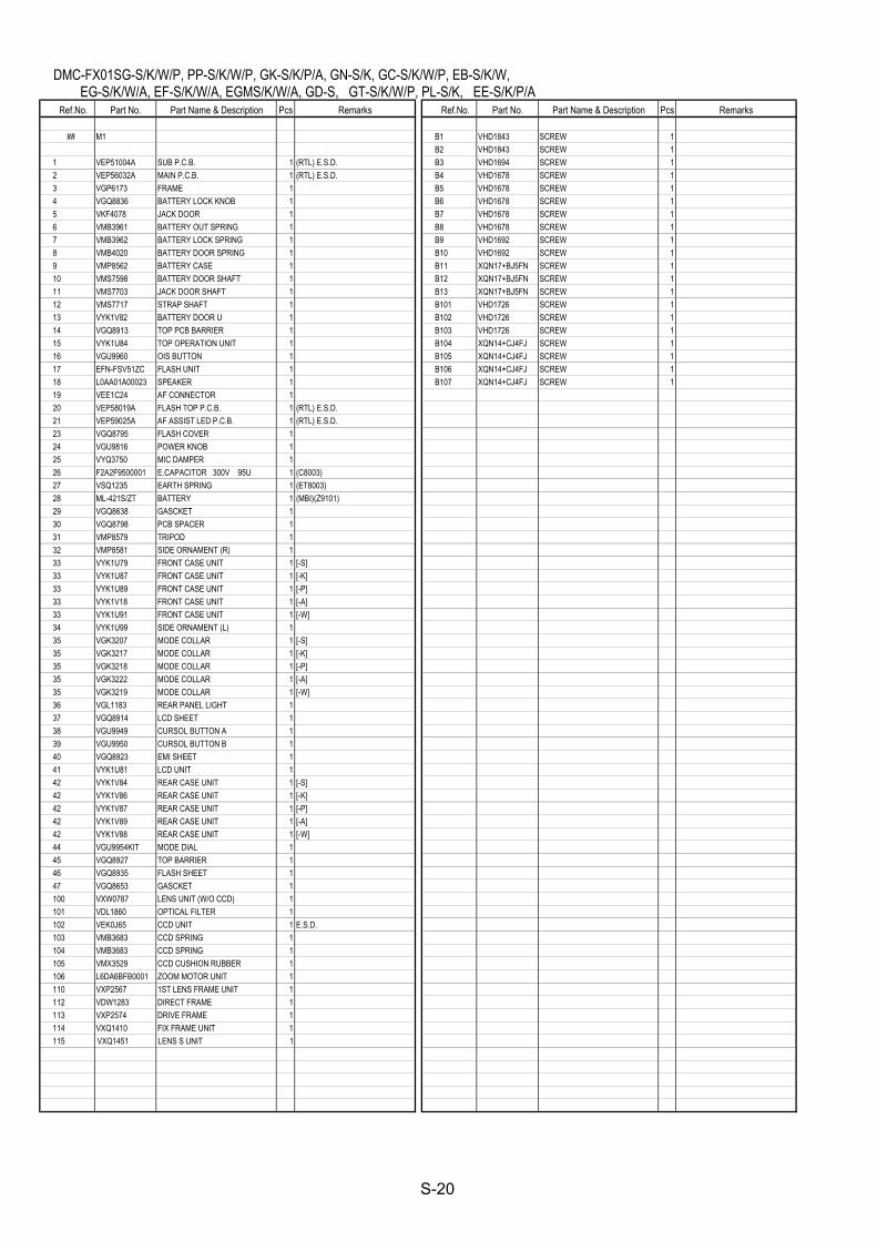
Ref.No. Part No. Part Name & Description Pcs Remarks Ref.No. Part No. Part Name & Description Pcs Remarks ## M1 B1 VHD1843 SCREW 1 B2 VHD1843 SCREW 1 1 VEP51004A SUB P.C.B. 1 (RTL) E.S.D. B3 VHD1694 SCREW 1 2 VEP56032A MAIN P.C.B. 1 (RTL) E.S.D. B4 VHD1678 SCREW 1 3 VGP6173 FRAME 1 B5 VHD1678 SCREW 1 4 VGQ8836 BATTERY LOCK KNOB 1 B6 VHD1678 SCREW 1 5 VKF4078 JACK DOOR 1 B7 VHD1678 SCREW 1 6 VMB3961 BATTERY OUT SPRING 1 B8 VHD1678 SCREW 1 7 VMB3962 BATTERY LOCK SPRING 1 B9 VHD1692 SCREW 1 8 VMB4020 BATTERY DOOR SPRING 1 B10 VHD1692 SCREW 1 9 VMP8562 BATTERY CASE 1 B11 XQN17+BJ5FN SCREW 1 10 VMS7598 BATTERY DOOR SHAFT 1 B12 XQN17+BJ5FN SCREW 1 11 VMS7703 JACK DOOR SHAFT 1 B13 XQN17+BJ5FN SCREW 1 12 VMS7717 STRAP SHAFT 1 B101 VHD1726 SCREW 1 13 VYK1V82 BATTERY DOOR U 1 B102 VHD1726 SCREW 1 14 VGQ8913 TOP PCB BARRIER 1 B103 VHD1726 SCREW 1 15 VYK1U84 TOP OPERATION UNIT 1 B104 XQN14+CJ4FJ SCREW 1 16 VGU9960 OIS BUTTON 1 B105 XQN14+CJ4FJ SCREW 1 17 EFN-FSV51ZC FLASH UNIT 1 B106 XQN14+CJ4FJ SCREW 1 18 L0AA01A00023 SPEAKER 1 B107 XQN14+CJ4FJ SCREW 1 19 VEE1C24 AF CONNECTOR 1 20 VEP58019A FLASH TOP P.C.B. 1 (RTL) E.S.D. 21 VEP59025A AF ASSIST LED P.C.B. 1 (RTL) E.S.D. 23 VGQ8795 FLASH COVER 1 24 VGU9816 POWER KNOB 1 25 VYQ3750 MIC DAMPER 1 26 F2A2F9500001 E.CAPACITOR 300V 95U 1 (C8003) 27 VSQ1235 EARTH SPRING 1 (ET8003) 28 ML-421S/ZT BATTERY 1 (MBI)(Z9101) 29 VGQ8638 GASCKET 1 30 VGQ8798 PCB SPACER 1 31 VMP8579 TRIPOD 1 32 VMP8581 SIDE ORNAMENT (R) 1 33 VYK1U79 FRONT CASE UNIT 1 [-S] 33 VYK1U87 FRONT CASE UNIT 1 [-K] 33 VYK1U89 FRONT CASE UNIT 1 [-P] 33 VYK1V18 FRONT CASE UNIT 1 [-A] 33 VYK1U91 FRONT CASE UNIT 1 [-W] 34 VYK1U99 SIDE ORNAMENT (L) 1 35 VGK3207 MODE COLLAR 1 [-S] 35 VGK3217 MODE COLLAR 1 [-K] 35 VGK3218 MODE COLLAR 1 [-P] 35 VGK3222 MODE COLLAR 1 [-A] 35 VGK3219 MODE COLLAR 1 [-W] 36 VGL1183 REAR PANEL LIGHT 1 37 VGQ8914 LCD SHEET 1 38 VGU9949 CURSOL BUTTON A 1 39 VGU9950 CURSOL BUTTON B 1 40 VGQ8923 EMI SHEET 1 41 VYK1U81 LCD UNIT 1 42 VYK1V84 REAR CASE UNIT 1 [-S] 42 VYK1V86 REAR CASE UNIT 1 [-K] 42 VYK1V87 REAR CASE UNIT 1 [-P] 42 VYK1V89 REAR CASE UNIT 1 [-A] 42 VYK1V88 REAR CASE UNIT 1 [-W] 44 VGU9954KIT MODE DIAL 1 45 VGQ8927 TOP BARRIER 1 46 VGQ8935 FLASH SHEET 1 47 VGQ8653 GASCKET 1 100 VXW0787 LENS UNIT (W/O CCD) 1 101 VDL1860 OPTICAL FILTER 1 102 VEK0J65 CCD UNIT 1 E.S.D. 103 VMB3683 CCD SPRING 1 104 VMB3683 CCD SPRING 1 105 VMX3529 CCD CUSHION RUBBER 1 106 L6DA6BFB0001 ZOOM MOTOR UNIT 1 110 VXP2567 1ST LENS FRAME UNIT 1 112 VDW1283 DIRECT FRAME 1 113 VXP2574 DRIVE FRAME 1 114 VXQ1410 FIX FRAME UNIT 1 115 VXQ1451 LENS S UNIT 1
S-20
DMC-FX01SG-S/K/W/P, PP-S/K/W/P, GK-S/K/P/A, GN-S/K, GC-S/K/W/P, EB-S/K/W, EG-S/K/W/A, EF-S/K/W/A, EGMS/K/W/A, GD-S, GT-S/K/W/P, PL-S/K, EE-S/K/P/A
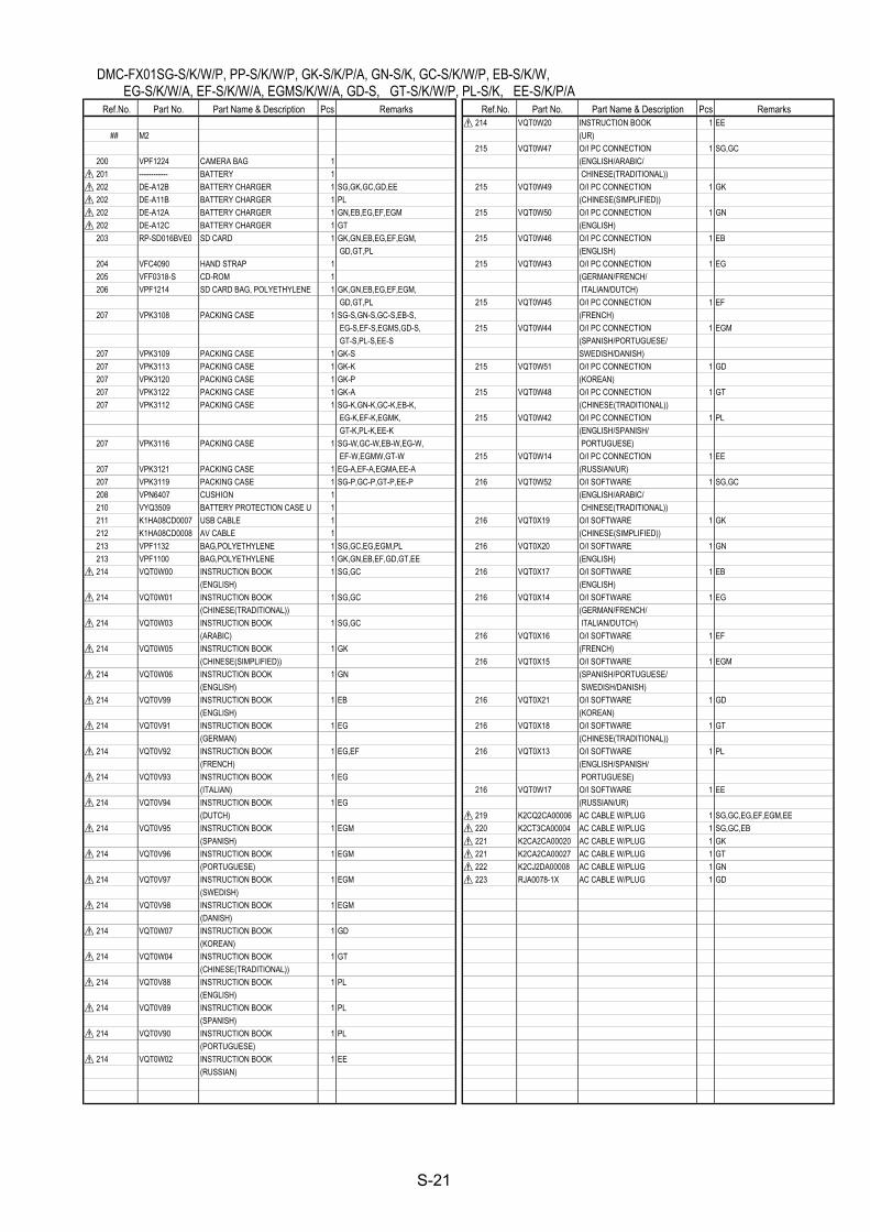
Ref.No. Part No. Part Name & Description Pcs Remarks Ref.No. Part No. Part Name & Description Pcs Remarks 214 VQT0W20 INSTRUCTION BOOK 1 EE ## M2 (UR) 215 VQT0W47 O/I PC CONNECTION 1 SG,GC 200 VPF1224 CAMERA BAG 1 (ENGLISH/ARABIC/ 201 ------------ BATTERY 1 CHINESE(TRADITIONAL)) 202 DE-A12B BATTERY CHARGER 1 SG,GK,GC,GD,EE 215 VQT0W49 O/I PC CONNECTION 1 GK 202 DE-A11B BATTERY CHARGER 1 PL (CHINESE(SIMPLIFIED)) 202 DE-A12A BATTERY CHARGER 1 GN,EB,EG,EF,EGM 215 VQT0W50 O/I PC CONNECTION 1 GN 202 DE-A12C BATTERY CHARGER 1 GT (ENGLISH) 203 RP-SD016BVE0 SD CARD 1 GK,GN,EB,EG,EF,EGM, 215 VQT0W46 O/I PC CONNECTION 1 EB GD,GT,PL (ENGLISH) 204 VFC4090 HAND STRAP 1 215 VQT0W43 O/I PC CONNECTION 1 EG 205 VFF0318-S CD-ROM 1 (GERMAN/FRENCH/ 206 VPF1214 SD CARD BAG, POLYETHYLENE 1 GK,GN,EB,EG,EF,EGM, ITALIAN/DUTCH) GD,GT,PL 215 VQT0W45 O/I PC CONNECTION 1 EF 207 VPK3108 PACKING CASE 1 SG-S,GN-S,GC-S,EB-S, (FRENCH) EG-S,EF-S,EGMS,GD-S, 215 VQT0W44 O/I PC CONNECTION 1 EGM GT-S,PL-S,EE-S (SPANISH/PORTUGUESE/ 207 VPK3109 PACKING CASE 1 GK-S SWEDISH/DANISH) 207 VPK3113 PACKING CASE 1 GK-K 215 VQT0W51 O/I PC CONNECTION 1 GD 207 VPK3120 PACKING CASE 1 GK-P (KOREAN) 207 VPK3122 PACKING CASE 1 GK-A 215 VQT0W48 O/I PC CONNECTION 1 GT 207 VPK3112 PACKING CASE 1 SG-K,GN-K,GC-K,EB-K, (CHINESE(TRADITIONAL)) EG-K,EF-K,EGMK, 215 VQT0W42 O/I PC CONNECTION 1 PL GT-K,PL-K,EE-K (ENGLISH/SPANISH/ 207 VPK3116 PACKING CASE 1 SG-W,GC-W,EB-W,EG-W, PORTUGUESE) EF-W,EGMW,GT-W 215 VQT0W14 O/I PC CONNECTION 1 EE 207 VPK3121 PACKING CASE 1 EG-A,EF-A,EGMA,EE-A (RUSSIAN/UR) 207 VPK3119 PACKING CASE 1 SG-P,GC-P,GT-P,EE-P 216 VQT0W52 O/I SOFTWARE 1 SG,GC 208 VPN6407 CUSHION 1 (ENGLISH/ARABIC/ 210 VYQ3509 BATTERY PROTECTION CASE U 1 CHINESE(TRADITIONAL)) 211 K1HA08CD0007 USB CABLE 1 216 VQT0X19 O/I SOFTWARE 1 GK 212 K1HA08CD0008 AV CABLE 1 (CHINESE(SIMPLIFIED)) 213 VPF1132 BAG,POLYETHYLENE 1 SG,GC,EG,EGM,PL 216 VQT0X20 O/I SOFTWARE 1 GN 213 VPF1100 BAG,POLYETHYLENE 1 GK,GN,EB,EF,GD,GT,EE (ENGLISH) 214 VQT0W00 INSTRUCTION BOOK 1 SG,GC 216 VQT0X17 O/I SOFTWARE 1 EB (ENGLISH) (ENGLISH) 214 VQT0W01 INSTRUCTION BOOK 1 SG,GC 216 VQT0X14 O/I SOFTWARE 1 EG (CHINESE(TRADITIONAL)) (GERMAN/FRENCH/ 214 VQT0W03 INSTRUCTION BOOK 1 SG,GC ITALIAN/DUTCH) (ARABIC) 216 VQT0X16 O/I SOFTWARE 1 EF 214 VQT0W05 INSTRUCTION BOOK 1 GK (FRENCH) (CHINESE(SIMPLIFIED)) 216 VQT0X15 O/I SOFTWARE 1 EGM 214 VQT0W06 INSTRUCTION BOOK 1 GN (SPANISH/PORTUGUESE/ (ENGLISH) SWEDISH/DANISH) 214 VQT0V99 INSTRUCTION BOOK 1 EB 216 VQT0X21 O/I SOFTWARE 1 GD (ENGLISH) (KOREAN) 214 VQT0V91 INSTRUCTION BOOK 1 EG 216 VQT0X18 O/I SOFTWARE 1 GT (GERMAN) (CHINESE(TRADITIONAL)) 214 VQT0V92 INSTRUCTION BOOK 1 EG,EF 216 VQT0X13 O/I SOFTWARE 1 PL (FRENCH) (ENGLISH/SPANISH/ 214 VQT0V93 INSTRUCTION BOOK 1 EG PORTUGUESE) (ITALIAN) 216 VQT0W17 O/I SOFTWARE 1 EE 214 VQT0V94 INSTRUCTION BOOK 1 EG (RUSSIAN/UR) (DUTCH) 219 K2CQ2CA00006 AC CABLE W/PLUG 1 SG,GC,EG,EF,EGM,EE 214 VQT0V95 INSTRUCTION BOOK 1 EGM 220 K2CT3CA00004 AC CABLE W/PLUG 1 SG,GC,EB (SPANISH) 221 K2CA2CA00020 AC CABLE W/PLUG 1 GK 214 VQT0V96 INSTRUCTION BOOK 1 EGM 221 K2CA2CA00027 AC CABLE W/PLUG 1 GT (PORTUGUESE) 222 K2CJ2DA00008 AC CABLE W/PLUG 1 GN 214 VQT0V97 INSTRUCTION BOOK 1 EGM 223 RJA0078-1X AC CABLE W/PLUG 1 GD (SWEDISH) 214 VQT0V98 INSTRUCTION BOOK 1 EGM (DANISH) 214 VQT0W07 INSTRUCTION BOOK 1 GD (KOREAN) 214 VQT0W04 INSTRUCTION BOOK 1 GT (CHINESE(TRADITIONAL)) 214 VQT0V88 INSTRUCTION BOOK 1 PL (ENGLISH) 214 VQT0V89 INSTRUCTION BOOK 1 PL (SPANISH) 214 VQT0V90 INSTRUCTION BOOK 1 PL (PORTUGUESE) 214 VQT0W02 INSTRUCTION BOOK 1 EE (RUSSIAN)
S-21
DMC-FX01SG-S/K/W/P, PP-S/K/W/P, GK-S/K/P/A, GN-S/K, GC-S/K/W/P, EB-S/K/W, EG-S/K/W/A, EF-S/K/W/A, EGMS/K/W/A, GD-S, GT-S/K/W/P, PL-S/K, EE-S/K/P/A
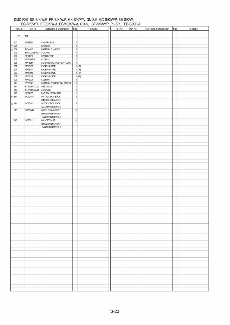
Ref.No. Part No. Part Name & Description Pcs Remarks Ref.No. Part No. Part Name & Description Pcs Remarks ## M3 300 VPF1224 CAMERA BAG 1 301 ------------ BATTERY 1 302 DE-A11B BATTERY CHARGER 1 303 RP-SD016BVE0 SD CARD 1 304 VFC4090 HAND STRAP 1 305 VFF0317-S CD-ROM 1 306 VPF1214 SD CARD BAG, POLYETHYLENE 1 307 VPK3107 PACKING CASE 1 [-S] 307 VPK3111 PACKING CASE 1 [-K] 307 VPK3115 PACKING CASE 1 [-W] 307 VPK3118 PACKING CASE 1 [-P] 308 VPN6335 CUSHION 1 310 VYQ3509 BATTERY PROTECTION CASE U 1 311 K1HA08CD0007 USB CABLE 1 312 K1HA08CD0008 AV CABLE 1 313 VPF1100 BAG,POLYETHYLENE 1 314 VQT0V86 INSTRUCTION BOOK 1 (ENGLISH(SPANISH)) 314 VQT0V87 INSTRUCTION BOOK 1 (CANADIAN FRENCH) 315 VQT0W41 O/I PC CONNECTION 1 (ENGLISH(SPANISH)/ CANADIAN FRENCH) 316 VQT0X12 O/I SOFTWARE 1 (ENGLISH(SPANISH)/ CANADIAN FRENCH)
S-22
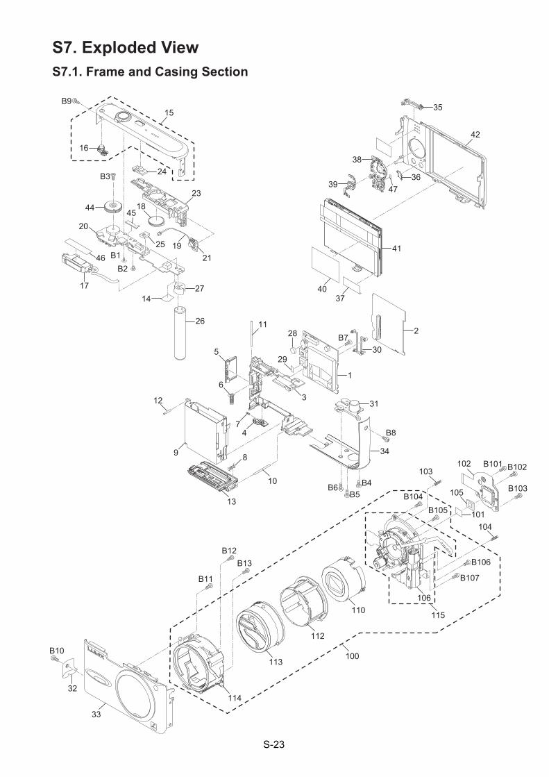
S7. Exploded View S7.1. Frame and Casing Section
S-23
B10
32
33
114
B13B12
B11
113
112
110106
101
105
102103
104
115
B101 B102
B103B104
B106
B107
37
11
3
5
6
12
2
30B7
1
31
B8
34
B4B5
B610
13
89
74
28
29
B105
100
17
20
B1B2
1427
26
19
2318
25
24
16
15B9
B3
44
21
45
46
40
41
39
38
36
35
42
47
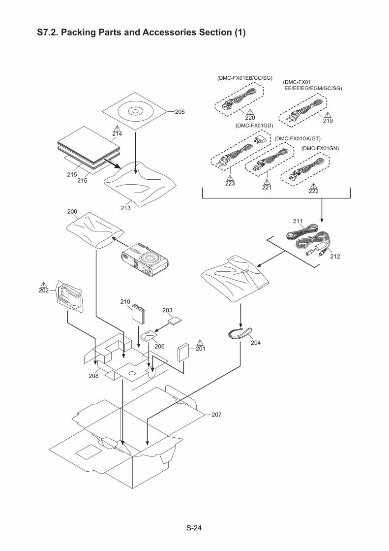
S7.2. Packing Parts and Accessories Section (1)
S-24
205
214
215216
213
202
204
203
206
208
200
207
201
(DMC-FX01EB/GC/SG)(DMC-FX01 EE/EF/EG/EGM/GC/SG)
(DMC-FX01GN)
(DMC-FX01GK/GT)
(DMC-FX01GD)
212
211
210
223221 222
219220
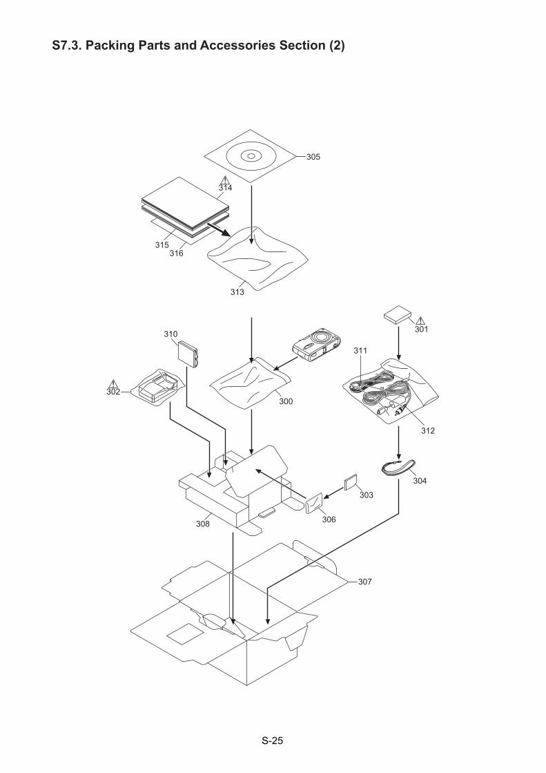
S7.3. Packing Parts and Accessories Section (2)
S-25
305
314
315316
313
310
302
311
304
303
306308
300
307
312
301
Related Documents