STUDENT'S POLYTECHNIC GUIDE BOOK ENGINEERING DRAWING VOL. 1 DJJ10013 Notes And Practical Works BY SITI ARFAH BINTI ABD JALIL MECHANICAL ENGINEERING DEPARTMENT 1ST EDITION

Welcome message from author
This document is posted to help you gain knowledge. Please leave a comment to let me know what you think about it! Share it to your friends and learn new things together.
Transcript
STUDENT'S POLYTECHNIC GUIDE BOOK
ENGINEERINGDRAWING VOL. 1
D J J 1 0 0 1 3
Notes And Practical Works
B Y S I T I A R F A H B I N T I A B D J A L I LM E C H A N I C A L E N G I N E E R I N G D E P A R T M E N T
1 S T E D I T I O N
DJJ10013
ENGINEERING DRAWING
VOL. 1
STUDENT'S POLYTECHNIC GUIDE BOOK
SITI ARFAH B INTI ABD JALIL
E N G I N E E R I N G D R A W I N G
A l l r i g h t r e s e r v e . N o par t s o f t h i s p u b l i cat i o n may b e r e p r o d u c e o r
t ran s m i t t e d i n an y f o r m s o r an y m ean s , e l e c t r o n i c o r m e c han i ca l
i n c l u d i n g p h o t o c o p y , r e c o r d i n g o r an y i n f o r mat i o n s t o rag e an d
r e t r i e va l s y s t e m , w i t h o u t p e r m i s s i o n i n w r i t i n g f r o m L i b rar y o f
P o l i t e k n i k T uan k u S u l tanah Bah i yah , K u l i m H i - T e c h Par k , 0 9 0 9 0 K u l i m ,
K e dah .
S I T I AR FAH B I N T I ABD JAL I L
L e c t u r e r
M e c han i ca l E n g i n e e r i n g D e par t m e n t
P o l i t e k n i k T uan k u S u l tanah Bah i yah
AUTHOR :
Copyright © 2021
ENGINEERING DRAWING | I
M e c han i ca l E n g i n e e r i n g D e par t m e n t
P o l i t e k n i k T uan k u S u l tanah Bah i yah
K u l i m H i - T e c h Par k ,
0 9 0 9 0 K u l i m ,
K e dah .
ar fah @ p t s b . e d u . m y
e I SBN 9 7 8 - 9 6 7 - 0 8 5 5 - 9 0 - 5

P R E F A C E
A l ham d u l i l lah t o A l lah S W T W i t h H i s g rac e an d m e r c y , t h e f i r s t e - b o o k
m o d u l e o f D J J 1 0 0 1 3 E n g i n e e r i n g D raw i n g has f i na l l y c o m p l e t e d . T han k
y o u t o m y fam i l y an d f r i e n d s e s p e c ia l l y P T SB e - b o o k t eam f o r b e i n g
s u p p o r t m e t o c o m p l e t e t h i s e - b o o k . I a l s o w o u l d l i k e t o t han k y o u t o m y
H ead o f M e c han i ca l E n g i n e e r i n g D e par t m e n t , E n . Az har B i n F i k r i f o r g i v i n g
t h i s o p p o r t u n i t y . As e d u cat o r , I f e e l t h e n e e d t o p r e par e a e - b o o k
m o d u l e t hat c o n s i s t o f n o t e s , s t e p b y s t e p p rac t i ca l w o r k s an d s o m e
e x e r c i s e s t hat can as s i s t t h e s t u d e n t i n t h e l ear n i n g p r o c e s s .
T h e c o n t e n t o f t h i s e - b o o k has b e e n c o n s t r u c t e d t o m e e t t h e
p o l y t e c h n i c ' s s y l lab u s r e q u i r e m e n t . S o m e c hap t e r c o n ta i n s i l l u s t rat i v e
s c r e e n s h o t s t o mat c h t h e ma i n p rac t i ca l w o r k , e n han c i n g s t u d e n t
c o m p r e h e n d i n g ab i l i t y . T h i s e - b o o k c o n ta i n s 5 c hap t e r s u c h as
I n t r o d u c t i o n T o T e c h n i ca l D raw i n g , G e o m e t r i ca l D raw i n g , O r t h o g rap h i c
P r o j e c t i o n an d I s o m e t r i c , G e o m e t r i c D i m e n s i o n i n g An d T o l e ran c e an d
S e c t i o na l V i e w .
An y p o s i t i v e f e e d bac k f r o m l e c t u r e r an d s t u d e n t ar e m o s t l y
w e l c o m e an d ap p r e c iat e d . H o p e f u l l y t h i s e - b o o k m o d u l e i s o n e o f t h e s t e p
t hat s tar t t h e l o n g j o u r n e y o f r oad t o e x c e l l e n t .
ENGINEERING DRAWING | I I

T A B L E O F C O N T E N T S
ENGINEERING DRAWING | I I I
D E C LARAT I O N
P R E FAC E
DECLARATIONTABL E O F C O N T E N T
C HAP T E R 1 : I N T R O D U C T I O N T O
T E C H N I CAL D RAW I N G
C HAP T E R 2 : G E O M E T R I CAL
D RAW I N G
C HAP T E R 3 : O R T H O G RAP H I C
P R O J E C T I O N & I S O M E T R I C
C HAP T E R 4 : G E O M E T R I CAL
D I M E N S I O N I N G & T O L E RAN C E
C HAP T E R 5 : S E C T I O NAL V I E W
I
II
III
1
35
63
110
133
Purpose and types of technical drawings
Engineering drawings instruments and their uses.
Basic mechanical drawing symbols.
Dimensioning symbols according to technical drawing
standard.
Learning Outcomes
CHAPTER 1
INTRODUCTION TO
TECHNICAL
DRAWING
INTRODUCTION TO TECHNICAL DRAWING | I
1.1 PURPOSE OF TECHNICAL
DRAWING
INTRODUCTION TO TECHNICAL DRAWING | 2
1.1 INTRODUCTION
The main purpose of engineering
drawings is to communicate to other
engineers, machinists, etc.
1.1.2 CATEGORIES OF
ENGINEERING DRAWING
1.1.1 MAIN PURPOSE OF
ENGINEERING DRAWING
Geometrical Drawing
Mechanical Drawing
Civil Engineering Drawing
Electrical Drawing
INTRODUCTION TO TECHNICAL DRAWING | 3
1.1.3 DRAWING EQUIPMENT AND MATERIALS
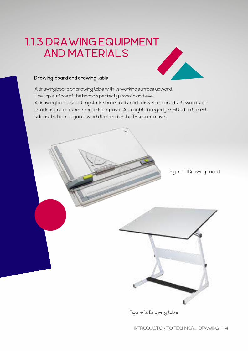
Drawing board and drawing table
A drawing board or drawing table with its working surface upward.
The top surface of the board is perfectly smooth and level.
A drawing board is rectangular in shape and is made of well seasoned soft wood such
as oak or pine or other is made from plastic. A straight ebony edge is fitted on the left
side on the board against which the head of the T- square moves.
Figure 1.1 Drawing board
Figure 1.2 Drawing table
INTRODUCTION TO TECHNICAL DRAWING | 4
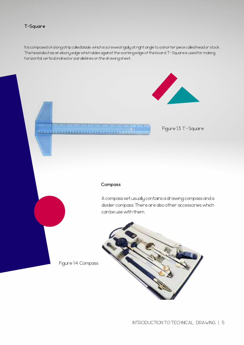
T-Square
Compass
It is composed of a long strip called blade, which is screwed rigidly at right angle to a shorter piece called head or stock.
The head also has an ebony edge which slides against the working edge of the board. T- Square is used for making
horizontal, vertical, inclined or parallel lines on the drawing sheet..
Figure 1.3 T - Square
Figure 1.4 Compass
A compass set usually contains a drawing compass and a
divider compass. There are also other accessories which
can be use with them.
INTRODUCTION TO TECHNICAL DRAWING | 5
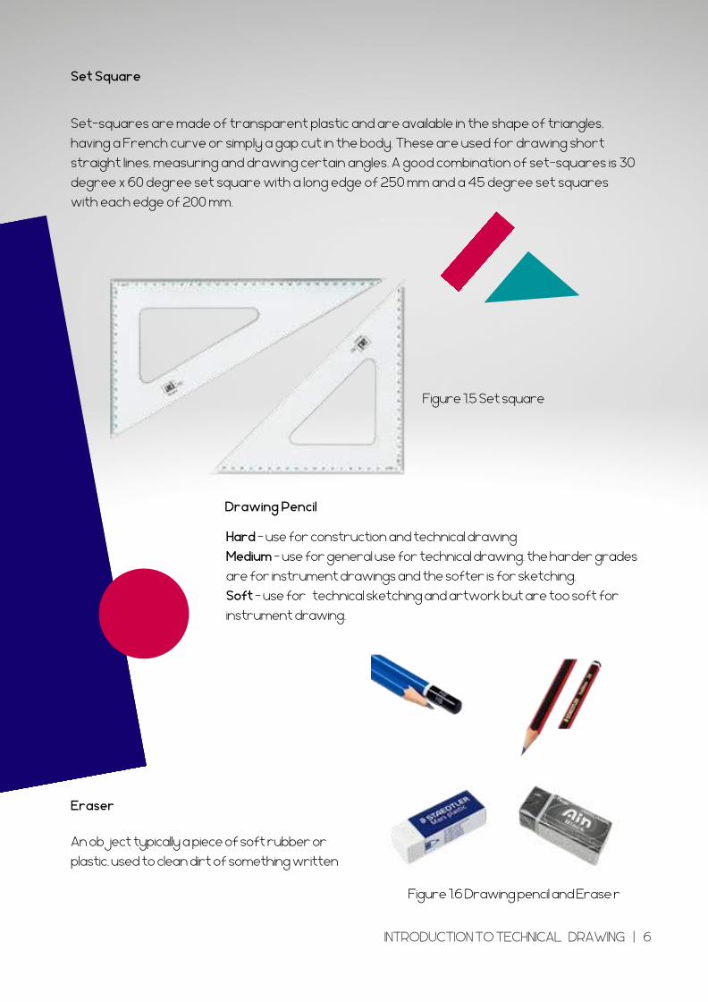
Set Square
Drawing Pencil
Eraser
Figure 1.5 Set square
Set-squares are made of transparent plastic and are available in the shape of triangles,
having a French curve or simply a gap cut in the body. These are used for drawing short
straight lines, measuring and drawing certain angles. A good combination of set-squares is 30
degree x 60 degree set square with a long edge of 250 mm and a 45 degree set squares
with each edge of 200 mm.
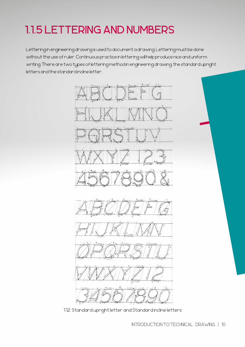
Hard - use for construction and technical drawing
Medium - use for general use for technical drawing. the harder grades
are for instrument drawings and the softer is for sketching.
Soft - use for technical sketching and artwork but are too soft for
instrument drawing.
Figure 1.6 Drawing pencil and Erase r
An object typically a piece of soft rubber or
plastic, used to clean dirt of something written
INTRODUCTION TO TECHNICAL DRAWING | 6
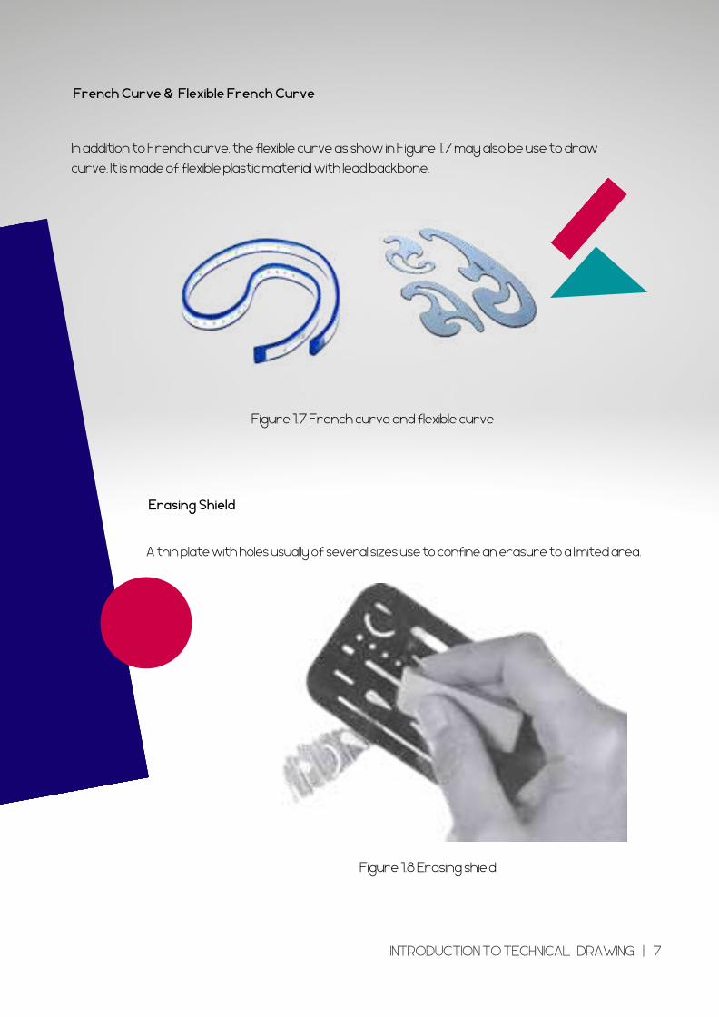
French Curve & Flexible French Curve
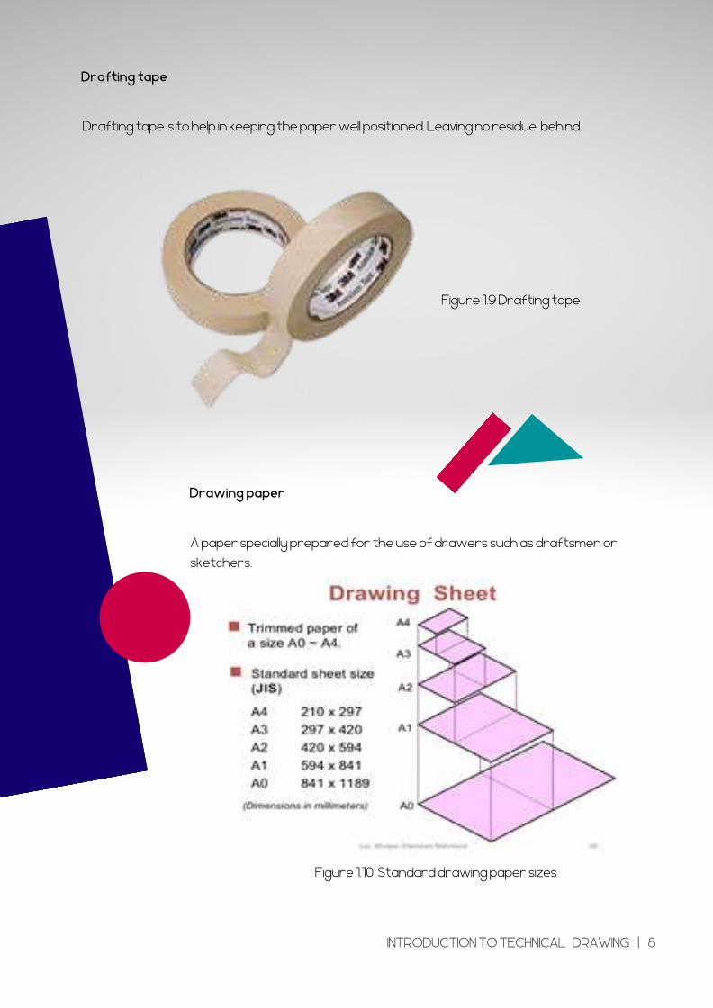
Erasing Shield
In addition to French curve, the flexible curve as show in Figure 1.7 may also be use to draw
curve. It is made of flexible plastic material with lead backbone.
Figure 1.7 French curve and flexible curve
Figure 1.8 Erasing shield
A thin plate with holes usually of several sizes use to confine an erasure to a limited area.
INTRODUCTION TO TECHNICAL DRAWING | 7
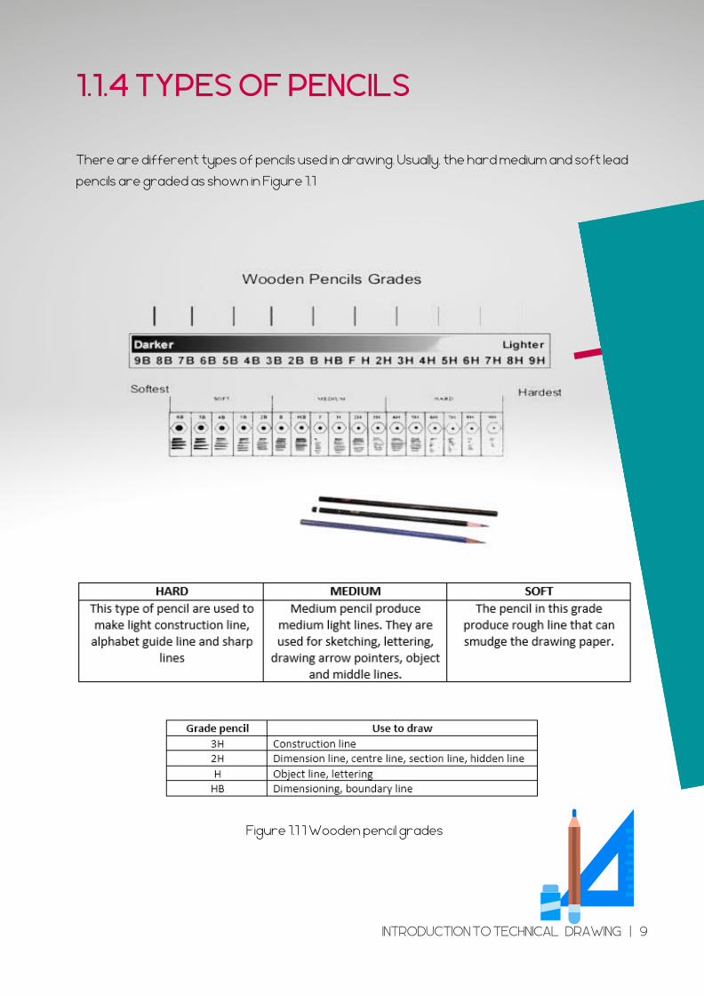
Drafting tape
Drawing paper
Drafting tape is to help in keeping the paper well positioned. Leaving no residue behind.
Figure 1.9 Drafting tape
Figure 1.10 Standard drawing paper sizes
A paper specially prepared for the use of drawers such as draftsmen or
sketchers.
INTRODUCTION TO TECHNICAL DRAWING | 8
There are different types of pencils used in drawing. Usually, the hard medium and soft lead
pencils are graded as shown in Figure 1.1
1.1.4 TYPES OF PENCILS
Figure 1.1 1 Wooden pencil grades
INTRODUCTION TO TECHNICAL DRAWING | 9
Lettering in engineering drawing is used to document a drawing. Lettering must be done
without the use of ruler. Continuous practice in lettering will help produce nice and uniform
writing. There are two types of lettering method in engineering drawing, the standard upright
letters and the standard incline letter.
1.1.5 LETTERING AND NUMBERS
1.12 Standard upright letter and Standard incline letters
INTRODUCTION TO TECHNICAL DRAWING | 10
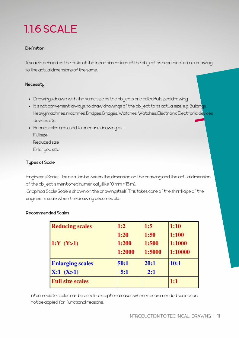
Drawings drawn with the same size as the objects are called full sized drawing.
It is not convenient, always, to draw drawings of the object to its actual size. e.g. Buildings,
Heavy machines, machines, Bridges, Bridges, Watches, Watches, Electronic Electronic devices
devices etc.
Hence scales are used to prepare drawing at :
Definition
A scale is defined as the ratio of the linear dimensions of the object as represented in a drawing
to the actual dimensions of the same.
Necessity
Full size
Reduced size
Enlarged size
1.1.6 SCALE
Types of Scale
•Engineers Scale : The relation between the dimension on the drawing and the actual dimension
of the object is mentioned numerically (like 10 mm = 15 m).
•Graphical Scale: Scale is drawn on the drawing itself. This takes care of the shrinkage of the
engineer’s scale when the drawing becomes old.
Recommended Scales
Intermediate scales can be used in exceptional cases where recommended scales can
not be applied for functional reasons.
INTRODUCTION TO TECHNICAL DRAWING | 11
1.2 TYPES OF SYMBOLS IN ENGINEERING DRAWING
WELDING SYMBOLPIPING SYMBOL MACHINE SYMBOL
INTRODUCTION TO TECHNICAL DRAWING | 12
1.2.1 WELDINGSYMBOLS
A weld is specified with a welding symbol and is
completed by the welder using the specified
process.
INTRODUCTION TO TECHNICAL DRAWING | 13
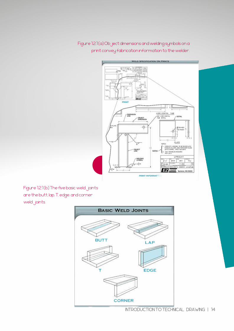
Figure 1.2.1 (b) The five basic weld joints
are the butt, lap, T, edge, and corner
weld joints.
Figure 1.2.1 (a) Object dimensions and welding symbols on a
print convey fabrication information to the welder.
INTRODUCTION TO TECHNICAL DRAWING | 14
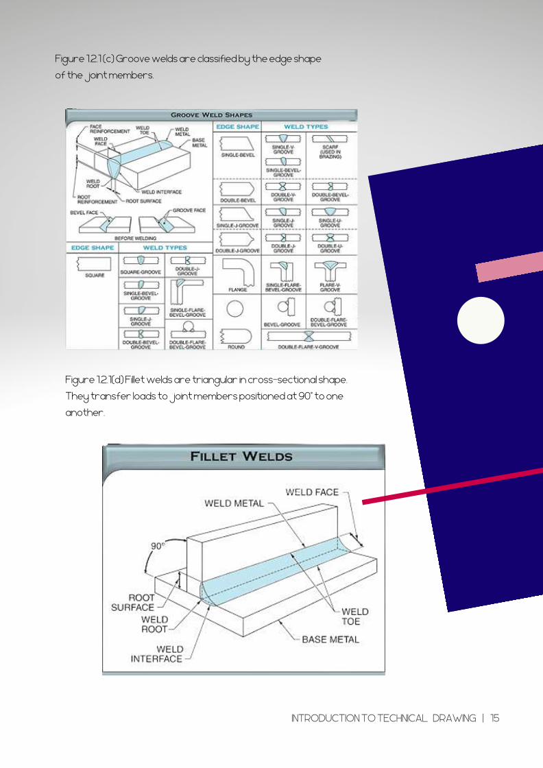
Figure 1.2.1 (c) Groove welds are classified by the edge shape
of the�joint members.
Figure 1.2.1(d) Fillet welds are triangular in cross-sectional shape.
They transfer loads to joint members positioned at 90° to one
another.
INTRODUCTION TO TECHNICAL DRAWING | 15
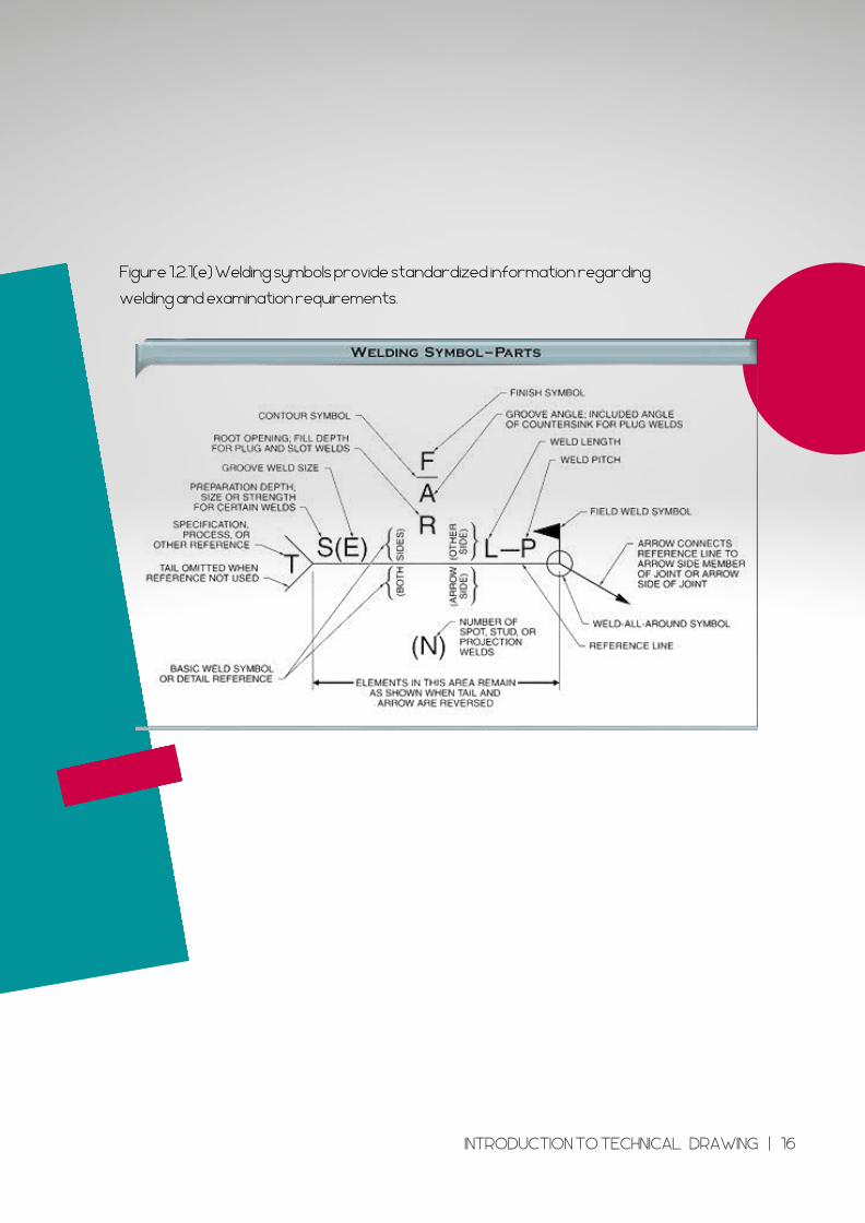
Figure 1.2.1(e) Welding symbols provide standardized information regarding
welding and examination requirements.
INTRODUCTION TO TECHNICAL DRAWING | 16
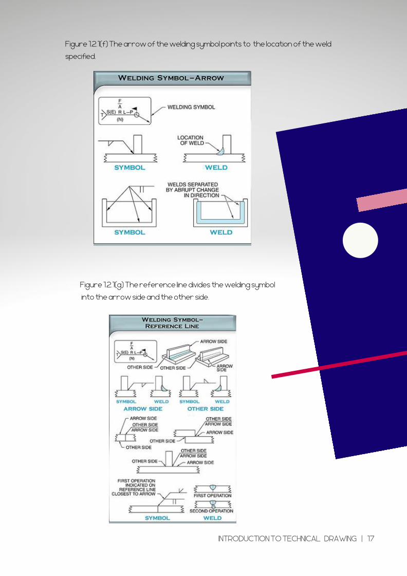
Figure 1.2.1(f) The arrow of the welding symbol points to the location of the weld
specified.
Figure 1.2.1(g) The reference line divides the welding symbol
into the arrow side and the other side.
INTRODUCTION TO TECHNICAL DRAWING | 17
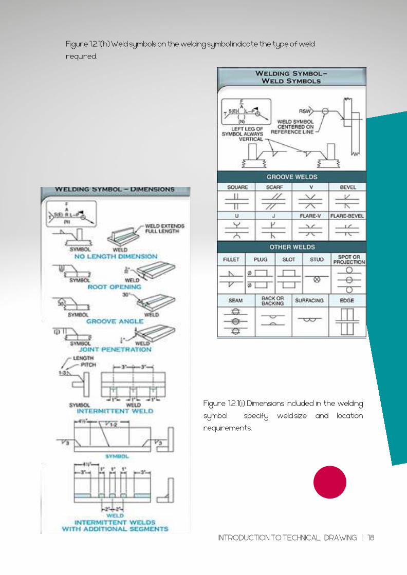
Figure 1.2.1(h) Weld symbols on the welding symbol indicate the type of weld
required.
Figure 1.2.1(i) Dimensions included in the welding
symbol specify weld�size and location
requirements.
INTRODUCTION TO TECHNICAL DRAWING | 18
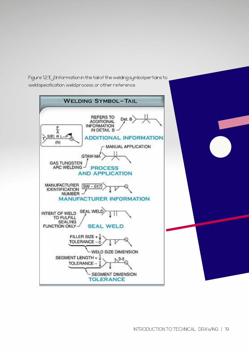
Figure 1.2.1(j) Information in the tail of the welding symbol pertains to
weld specification, weld process, or other reference.
INTRODUCTION TO TECHNICAL DRAWING | 19
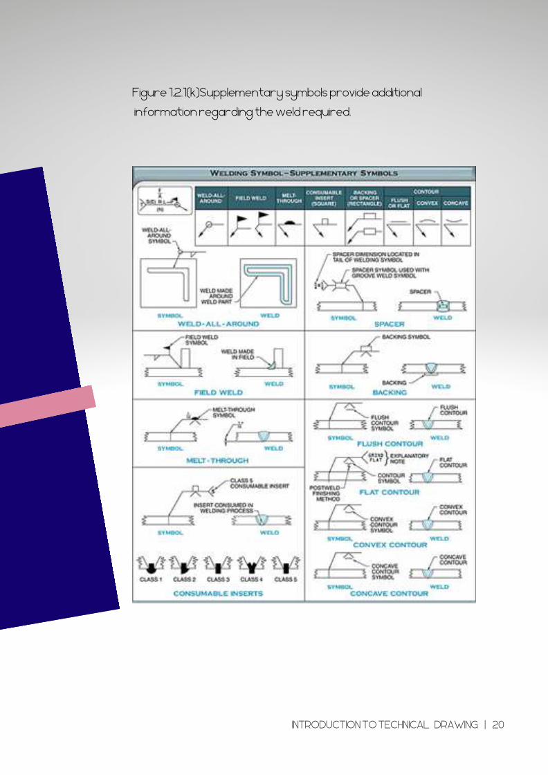
Figure 1.2.1(k)Supplementary symbols provide additional
information regarding the weld required.
INTRODUCTION TO TECHNICAL DRAWING | 20
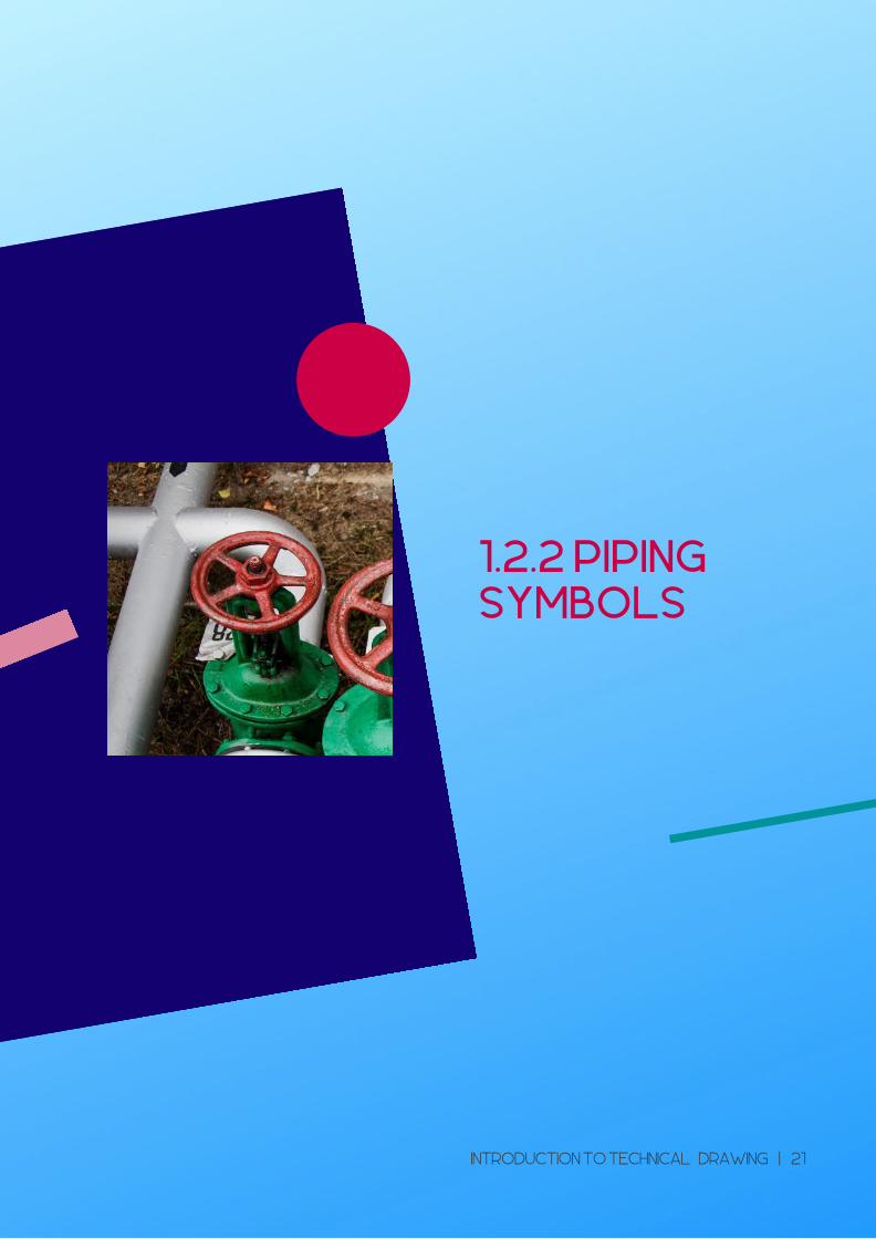
1.2.2 PIPING
SYMBOLS
INTRODUCTION TO TECHNICAL DRAWING | 21
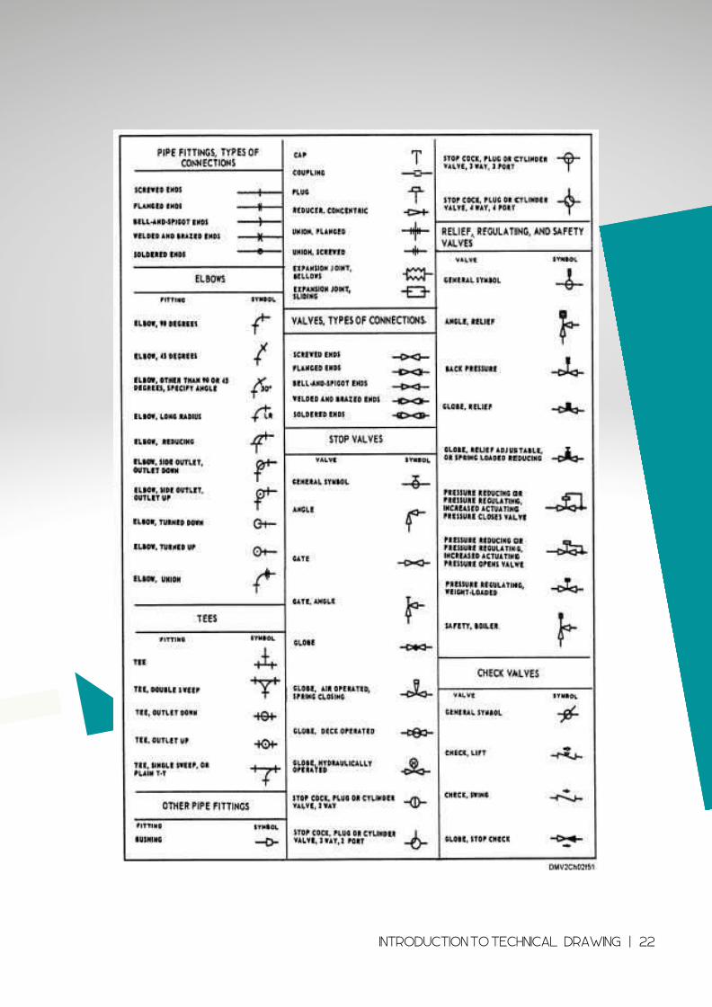
1Figure .2.2(a) Standard piping symbols
INTRODUCTION TO TECHNICAL DRAWING | 22
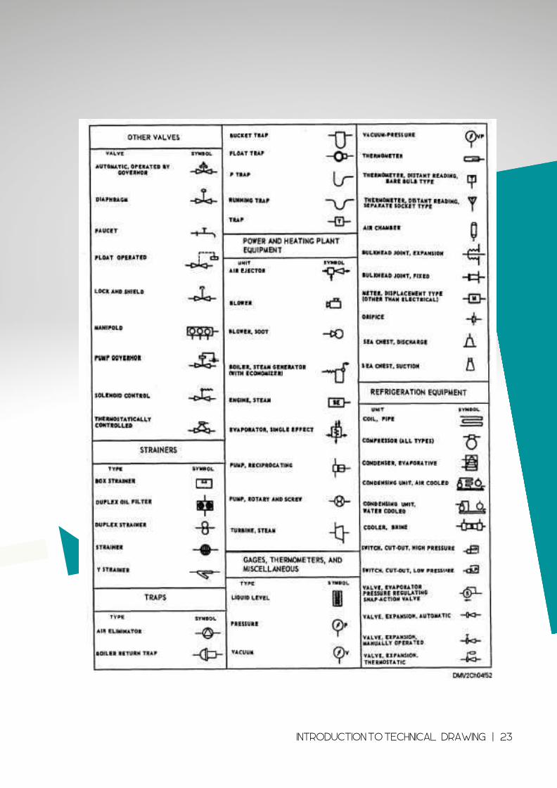
1Figure .2.2(b) Standard piping symbols
INTRODUCTION TO TECHNICAL DRAWING | 23
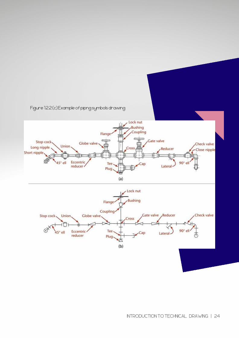
Figure 1.2.2 (c) Example of pipng symbols drawing
INTRODUCTION TO TECHNICAL DRAWING | 24

1.2.3 MACHINE
SYMBOL
INTRODUCTION TO TECHNICAL DRAWING | 25
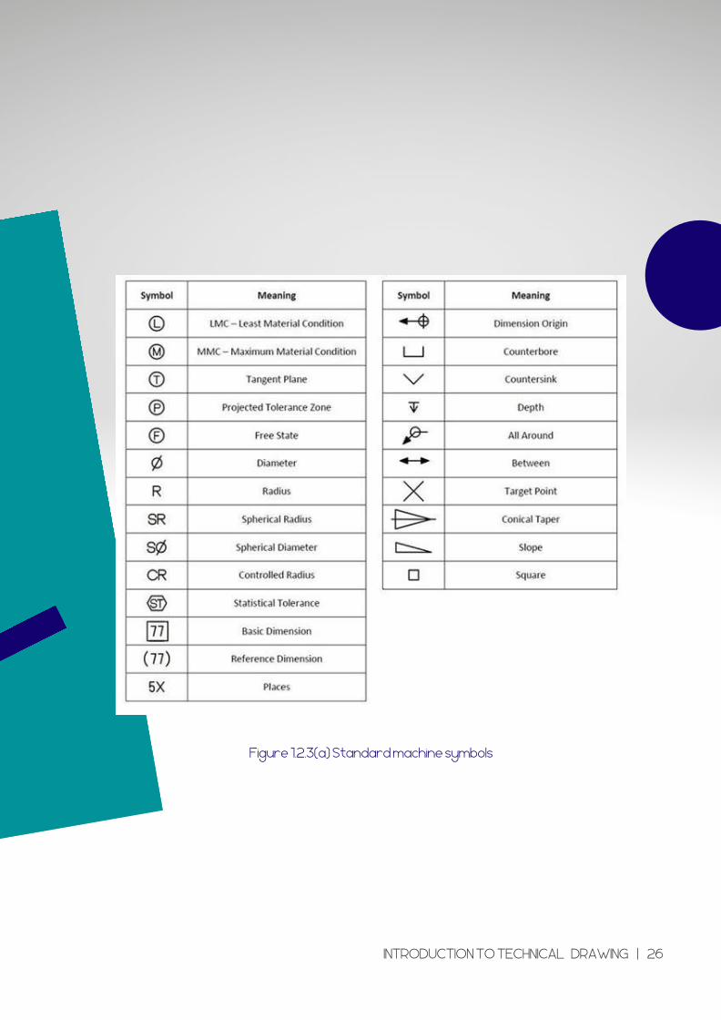
Figure 1.2.3(a) Standard machine symbols
INTRODUCTION TO TECHNICAL DRAWING | 26
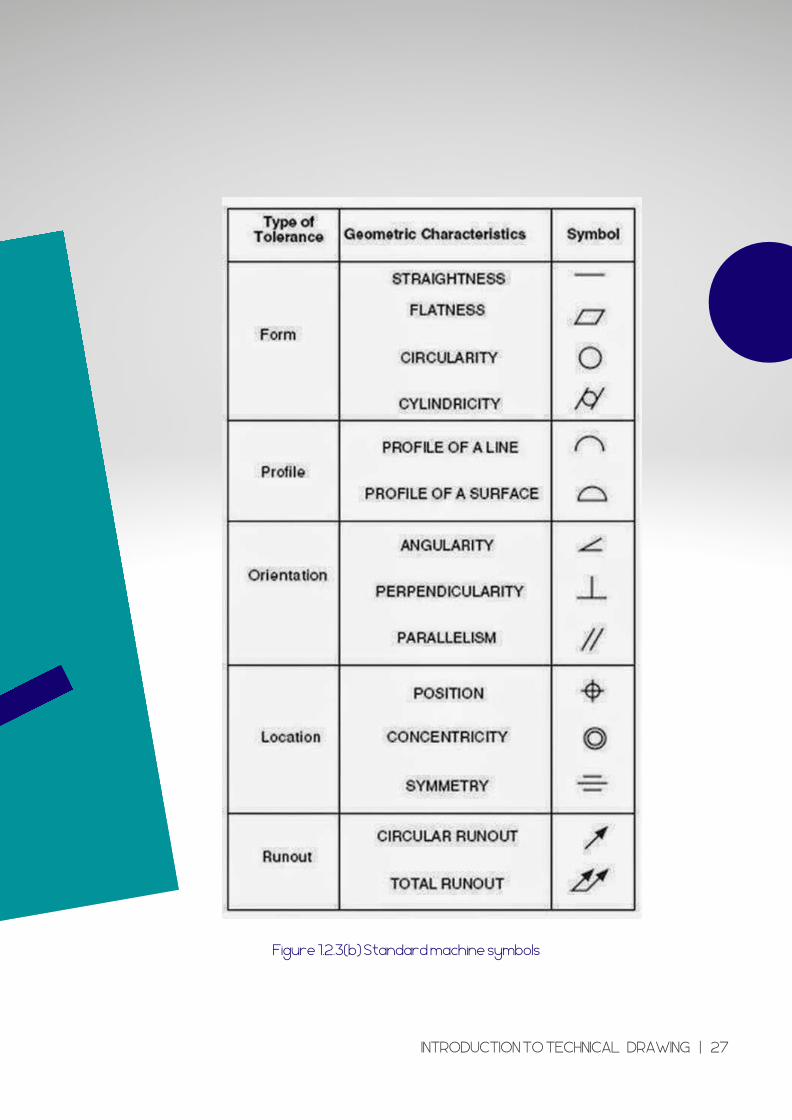
Figure 1.2.3(b) Standard machine symbols
INTRODUCTION TO TECHNICAL DRAWING | 27
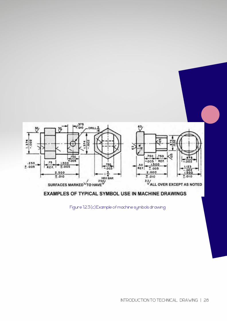
Figure 1.2.3 (c) Example of machine symbols drawing
INTRODUCTION TO TECHNICAL DRAWING | 28
1.3 DIMENSIONING
SYMBOL
INTRODUCTION TO TECHNICAL DRAWING | 29
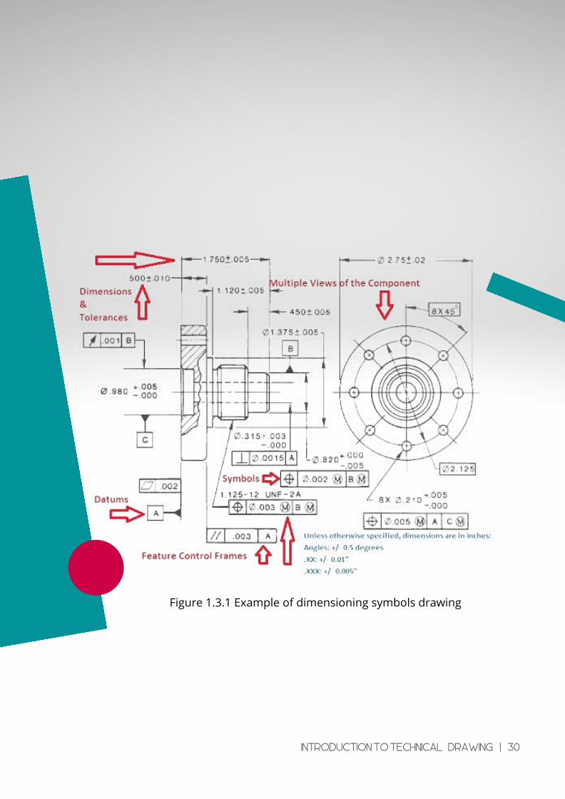
Figure 1.3.1 Example of dimensioning symbols drawing
INTRODUCTION TO TECHNICAL DRAWING | 30
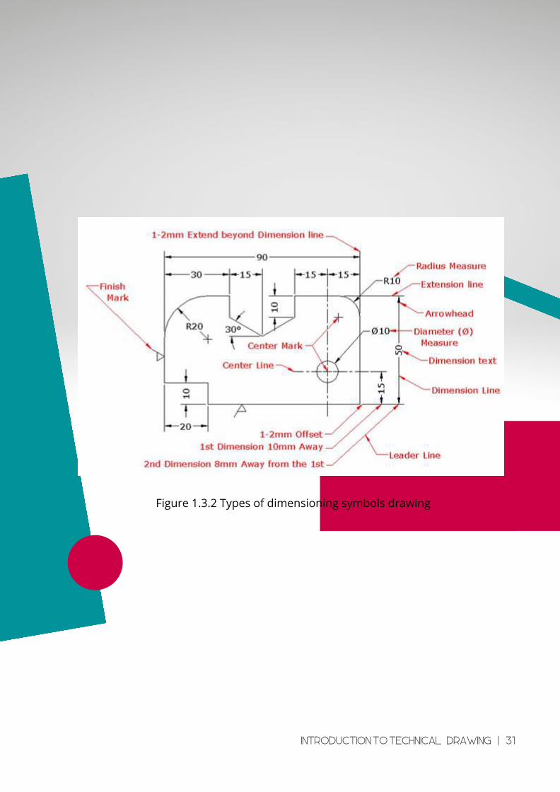
Figure 1.3.2 Types of dimensioning symbols drawing
INTRODUCTION TO TECHNICAL DRAWING | 31
TUTORIAL
CHAPTER 1
INTRODUCTION TO TECHNICAL DRAWING | 32
Tutorial 1
1.1 Differentiates between Engineering drawing, and illustration.
1.2 Describe the characteristic and function of drawing equipment and material below.
i. T – Square.
i. Set Squares
iii. French curve
1.3 What is differentiating between geometrical drawing and mechanical drawing?
1.4 The part that doesn’t belong to T-square is __________
a) Working edge b) Blade c) Stock d) Ebony
1.5 The angle which we can’t make using a single Set-square is ________
a) 45o b) 60o c) 30o d) 75o
1.6 Which is not the use of divider?
a) To divide curved or straight lines into the desired number of equal parts
b) To draw circles
c) To transfer dimensions from one part of the drawing to another part
d) To set-off given distances from the scale to the drawing
1.7 _________ is used to draw curves which are not circular.
a) Compass b) Protractor c) French curves d) Pro circle
1.8 The Grade becomes ______ according to the figure placed in front of the letter B, 2B, 3B, 4B etc.
a) harder b) lighter c) darker d) softer
INTRODUCTION TO TECHNICAL DRAWING | 33
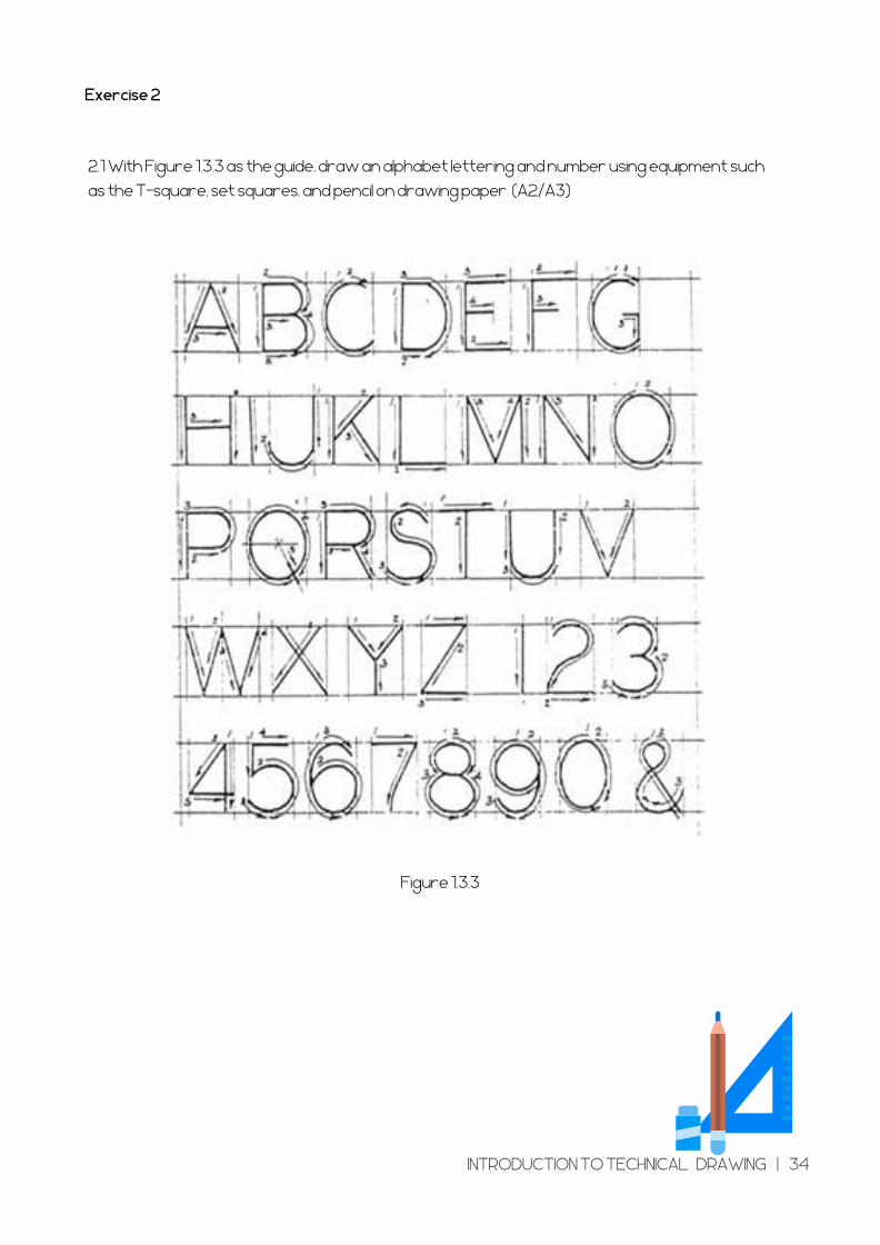
Exercise 2
2.1 With Figure 1.3.3 as the guide, draw an alphabet lettering and number using equipment such
as the T-square, set squares, and pencil on drawing paper (A2/A3)
Figure 1.3.3
INTRODUCTION TO TECHNICAL DRAWING | 34
C HAP T E R 2
GEOMETRICAL DRAWING
Learning Outcome
Basic geometrical drawing
Construct basic geometrical drawing.
- Different types of line and thickness.
- Types and the rules for lettering use on technical drawing.
- Title block according to standard required.
- Divide angle by using technical engineering drawing instruments.
- Geometrical shape using various methods.
GEOMETRICAL DRAWING | 35
In learning about geometry, graphic elements play a significant
role in producing a drawing. Graphic elements consist of point, line
and plane.
BASIC GEOMETRICALDRAWING
GEOMETRICAL DRAWING | 36
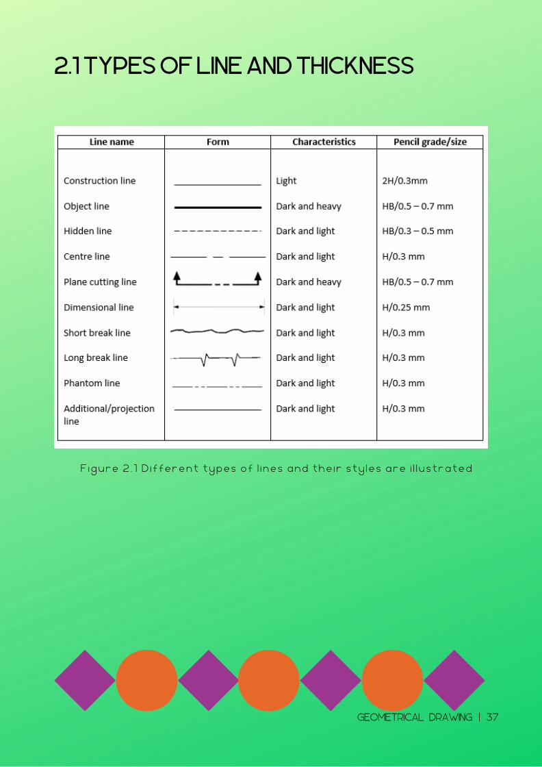
2.1 TYPES OF LINE AND THICKNESS
F i g u r e 2 . 1 D i f f e r e n t t y p e s o f l i n e s a n d t h e i r s t y l e s a r e i l l u s t r a t e d
GEOMETRICAL DRAWING | 37
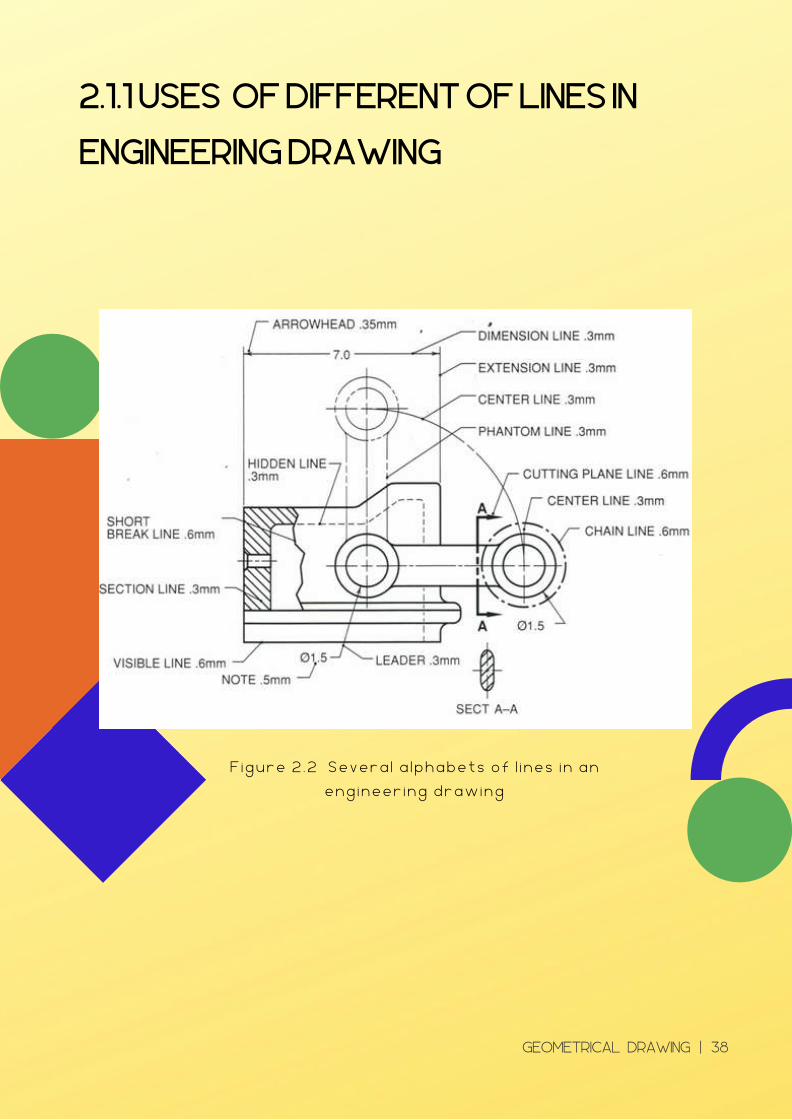
2.1.1 USES OF DIFFERENT OF LINES IN
ENGINEERING DRAWING
F i g u r e 2 . 2 S e v e r a l a l p h a b e t s o f l i n e s i n a n
e n g i n e e r i n g d r a w i n g
GEOMETRICAL DRAWING | 38
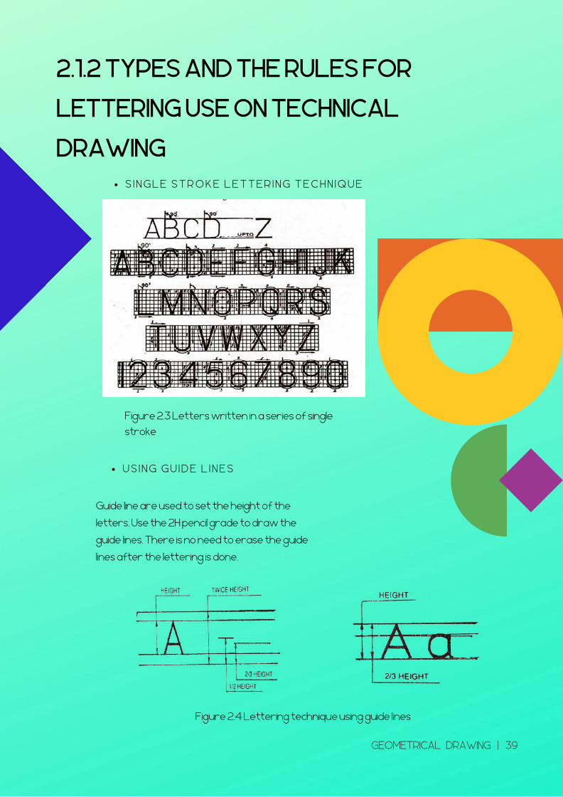
2.1.2 TYPES AND THE RULES FOR
LETTERING USE ON TECHNICAL
DRAWING S I N G L E S T R O K E L E T T E R I N G T E C H N I Q U E
U S I N G G U I D E L I N E S
Figure 2.3 Letters written in a series of single
stroke
Guide line are used to set the height of the
letters. Use the 2H pencil grade to draw the
guide lines. There is no need to erase the guide
lines after the lettering is done.
Figure 2.4 Lettering technique using guide lines
GEOMETRICAL DRAWING | 39
2.2 TITLE BLOCK
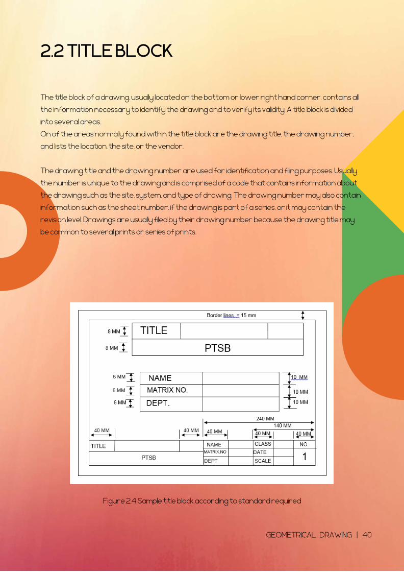
Figure 2.4 Sample title block according to standard required
The title block of a drawing, usually located on the bottom or lower right hand corner, contains all
the information necessary to identify the drawing and to verify its validity. A title block is divided
into several areas.
On of the areas normally found within the title block are the drawing title, the drawing number,
and lists the location, the site, or the vendor.
The drawing title and the drawing number are used for identification and filing purposes. Usually
the number is unique to the drawing and is comprised of a code that contains information about
the drawing such as the site, system, and type of drawing. The drawing number may also contain
information such as the sheet number, if the drawing is part of a series, or it may contain the
revision level. Drawings are usually filed by their drawing number because the drawing title may
be common to several prints or series of prints.
GEOMETRICAL DRAWING | 40
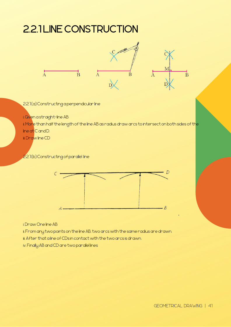
2.2.1 LINE CONSTRUCTION
i. Given a straight-line AB
ii. More than half the length of the line AB as radius draw arcs to intersect on both sides of the
line at C and D.
iii. Draw line CD
2.2.1 (a) Constructing a perpendicular line
2.2.1 (b) Constructing of parallel line
i. Draw One line AB
ii. From any two points on the line AB, two arcs with the same radius are drawn.
iii. After that a line of CDs in contact with the two arcs is drawn.
iv. Finally AB and CD are two parallel lines
GEOMETRICAL DRAWING | 41
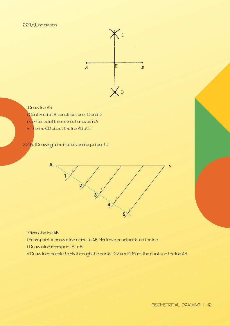
2.2.1(c)Line division
i. Draw line AB
ii. Centered at A, construct arcs C and D
iii. Centered at B construct arcs as in A
iv. The line CD bisect the line AB at E
D
C
E
2.2.1(d) Drawing a line into several equal parts
i. Given the line AB
ii. From point A, draw a line incline to AB. Mark five equal parts on the line
iii. Draw a line from point 5 to B
iv. Draw lines parallel to 5B through the points 1,2,3,and 4. Mark the points on the line AB.
GEOMETRICAL DRAWING | 42
2.2.2 ANGLES
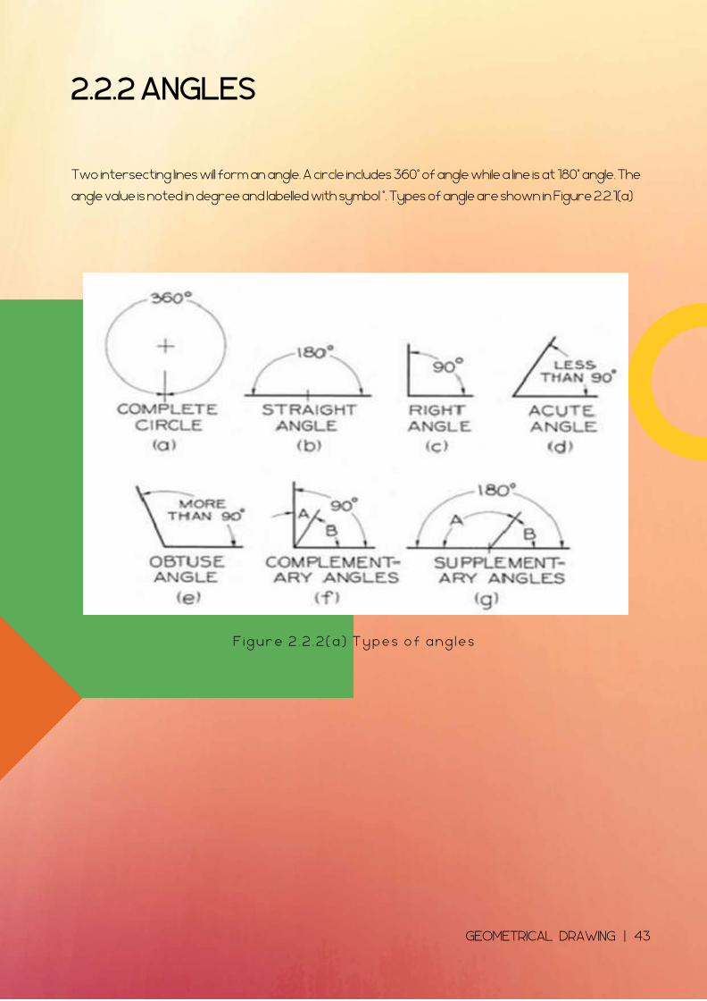
Two intersecting lines will form an angle. A circle includes 360° of angle while a line is at 180° angle. The
angle value is noted in degree and labelled with symbol °. Types of angle are shown in Figure 2.2.1(a)
F i g u r e 2 . 2 . 2 ( a ) T y p e s o f a n g l e s
GEOMETRICAL DRAWING | 43
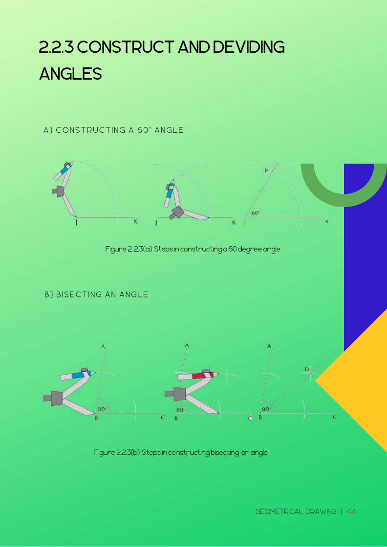
2.2.3 CONSTRUCT AND DEVIDING
ANGLES
A ) C O N S T R U C T I N G A 6 0 ° A N G L E
B ) B I S E C T I N G A N A N G L E
Figure 2..2.3(a) Steps in constructing a 60 degree angle
Figure 2.2.3(b) Steps in constructing bisecting an angle
GEOMETRICAL DRAWING | 44
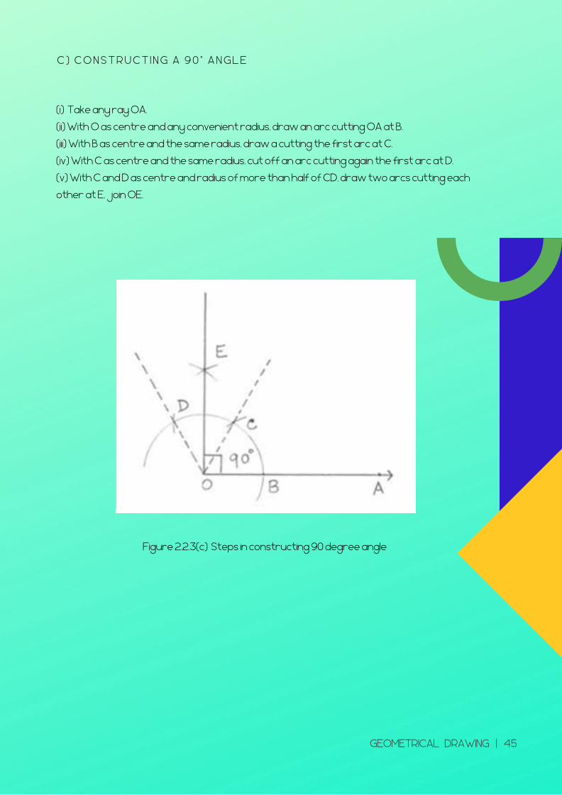
C ) C O N S T R U C T I N G A 9 0 ° A N G L E
(i) Take any ray OA.
(ii) With O as centre and any convenient radius, draw an arc cutting OA at B.
(iii) With B as centre and the same radius, draw a cutting the first arc at C.
(iv) With C as centre and the same radius, cut off an arc cutting again the first arc at D.
(v) With C and D as centre and radius of more than half of CD, draw two arcs cutting each
other at E, join OE.
Figure 2.2.3(c) Steps in constructing 90 degree angle
GEOMETRICAL DRAWING | 45
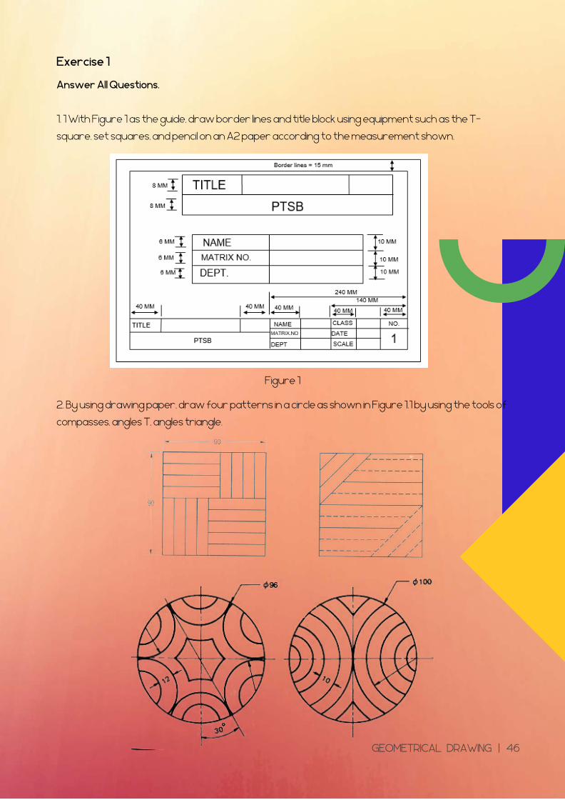
Exercise 1
Answer All Questions.
1. 1 With Figure 1 as the guide, draw border lines and title block using equipment such as the T-
square, set squares, and pencil on an A2 paper according to the measurement shown.
Figure 1
2. By using drawing paper, draw four patterns in a circle as shown in Figure 1.1 by using the tools of
compasses, angles T, angles triangle.
GEOMETRICAL DRAWING | 46
2.2.4 GEOMETRICAL SHAPE USING
VARIOUS METHOD
C I R C L E
T R I A N G L E
S Q UAR E
P O L Y G O N
E L L I P S E
GEOMETRICAL DRAWING | 47
2.2.4(i) Circle
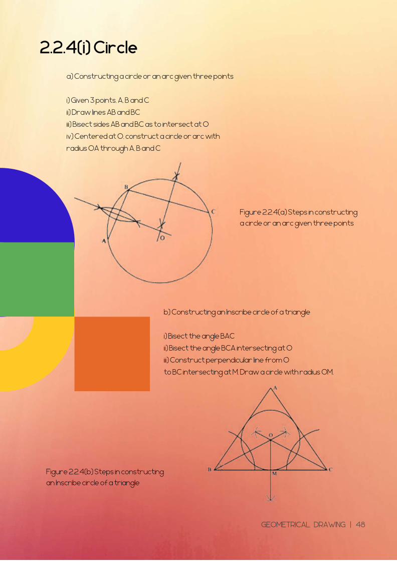
a) Constructing a circle or an arc given three points
i) Given 3 points, A, B and C
ii) Draw lines AB and BC
iii) Bisect sides AB and BC as to intersect at O
iv) Centered at O, construct a circle or arc with
radius OA through A, B and C
b) Constructing an Inscribe circle of a triangle
i) Bisect the angle BAC
ii) Bisect the angle BCA intersecting at O
iii) Construct perpendicular line from O
to BC intersecting at M. Draw a circle with radius OM.
Figure 2.2.4(a) Steps in constructing
a circle or an arc given three points
Figure 2.2.4(b) Steps in constructing
an Inscribe circle of a triangle
GEOMETRICAL DRAWING | 48
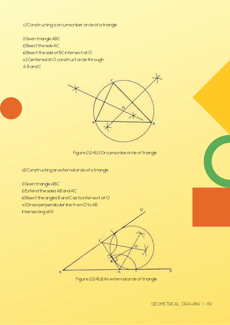
c) Constructing a circumscriber circle of a triangle
i) Given triangle ABC
ii) Bisect the side AC
iii) Bisect the side of BC intersect at O
iv) Centered at O, construct circle through
A, B and C
d) Constructing an external circle of a triangle
i) Given triangle ABC
ii) Extend the sides AB and AC
iii) Bisect the angles B and C as to intersect at O
iv) Draw perpendicular line from O to AB
Intersecting at R
Figure 2.2.4(c) Circumscribe circle of triangle
Figure 2.2.4(d) An external circle of triangle
GEOMETRICAL DRAWING | 49
2.2.4(ii) Triangle
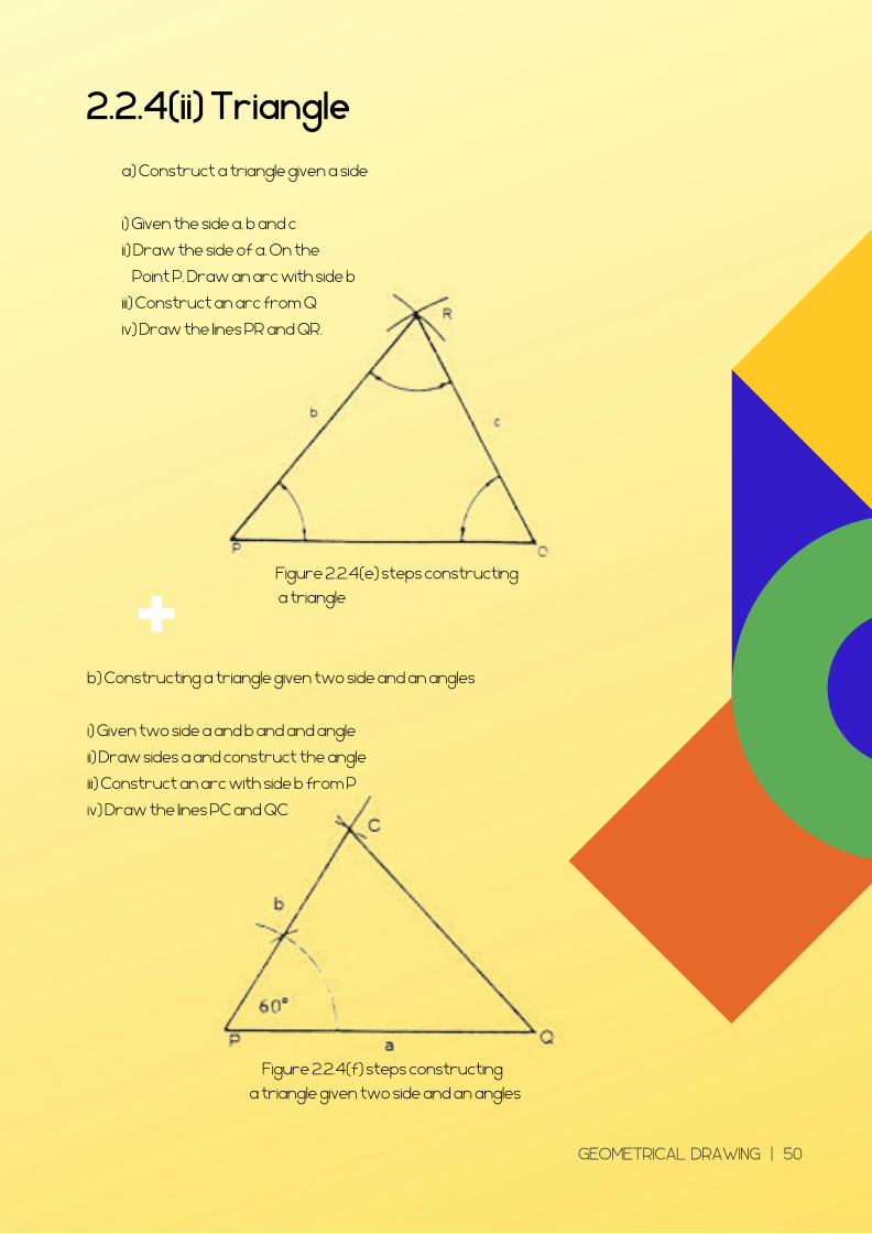
a) Construct a triangle given a side
i) Given the side a, b and c
ii) Draw the side of a. On the
Point P, Draw an arc with side b
iii) Construct an arc from Q
iv) Draw the lines PR and QR.
b) Constructing a triangle given two side and an angles
i) Given two side a and b and and angle
ii) Draw sides a and construct the angle
iii) Construct an arc with side b from P
iv) Draw the lines PC and QC
Figure 2.2.4(e) steps constructing
a triangle
Figure 2.2.4(f) steps constructing
a triangle given two side and an angles
GEOMETRICAL DRAWING | 50
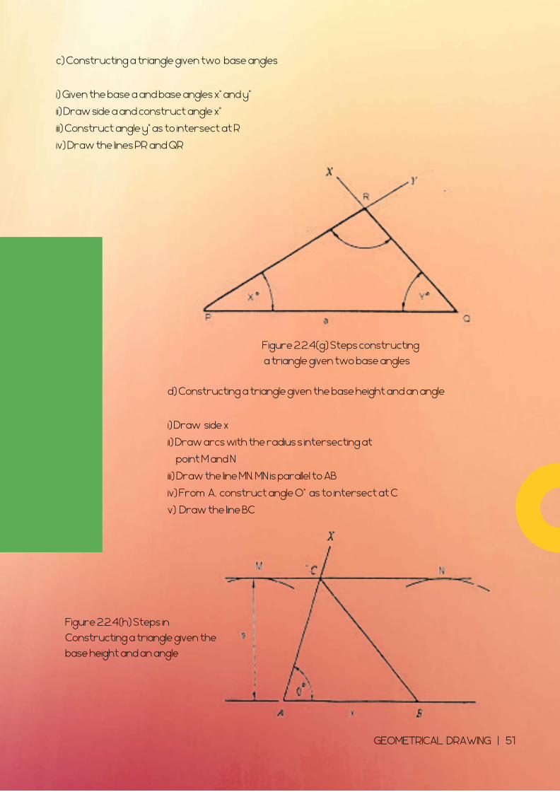
c) Constructing a triangle given two base angles
i) Given the base a and base angles x° and y°
ii) Draw side a and construct angle x°
iii) Construct angle y° as to intersect at R
iv) Draw the lines PR and QR
d) Constructing a triangle given the base height and an angle
i) Draw side x
ii) Draw arcs with the radius s intersecting at
point M and N
iii) Draw the line MN. MN is parallel to AB
iv) From A, construct angle O° as to intersect at C
v) Draw the line BC
Figure 2.2.4(g) Steps constructing
a triangle given two base angles
Figure 2.2.4(h) Steps in
Constructing a triangle given the
base height and an angle
GEOMETRICAL DRAWING | 51
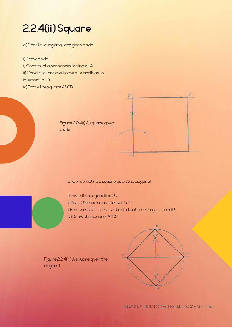
2.2.4(iii) Square
a) Constructing a square given a side
i) Draw a side
ii) Construct a perpendicular line at A
iii) Construct arcs with side at A and B as to
intersect at D
iv) Draw the square ABCD
b) Constructing a square given the diagonal
i) Given the diagonal line PR
ii) Bisect the line so as intersect at T
iii) Centred at T, construct a circle intersecting at P and R
iv) Draw the square PQRS
Figure 2.2.4(i) A square given
a side
Figure 2.2.4(j) A square given the
diagonal
INTRODUCTION TO TECHNICAL DRAWING | 52
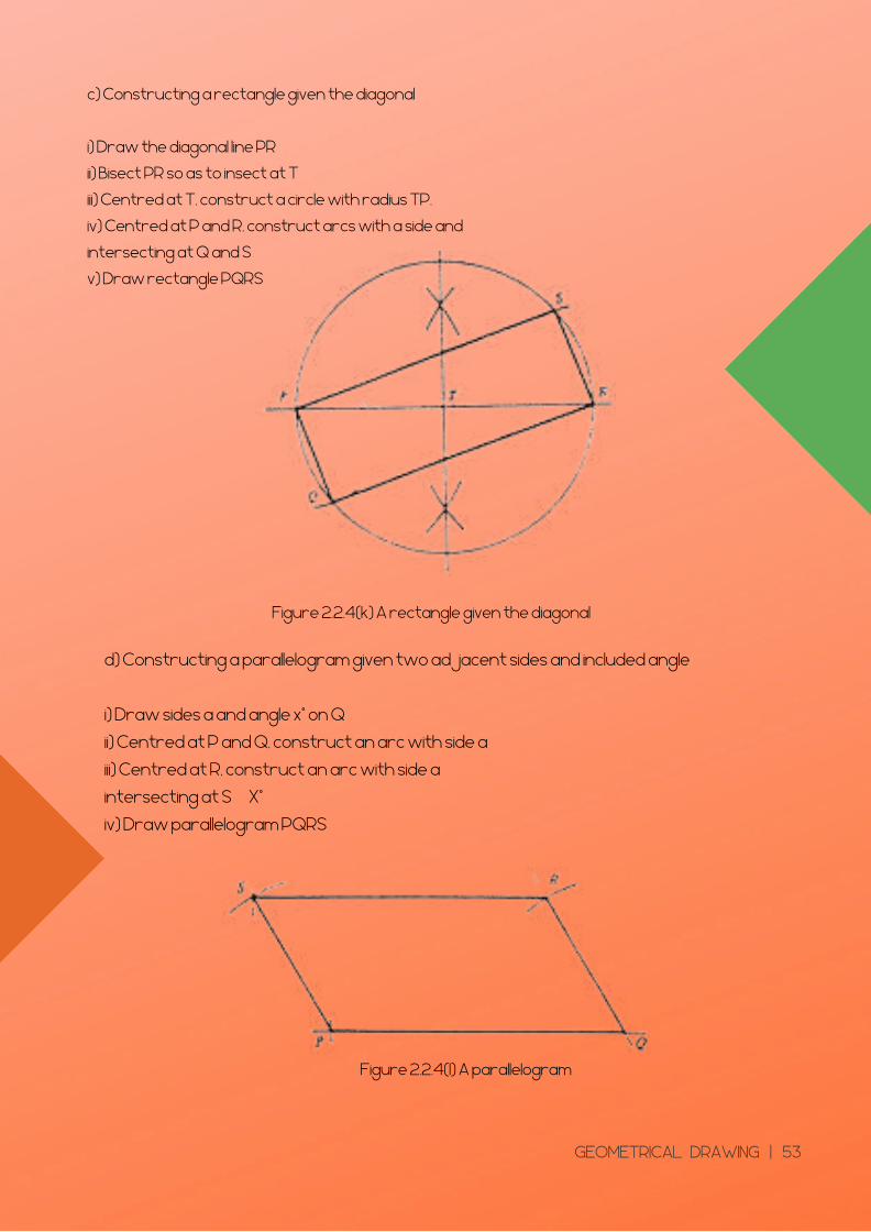
c) Constructing a rectangle given the diagonal
i) Draw the diagonal line PR
ii) Bisect PR so as to insect at T
iii) Centred at T, construct a circle with radius TP.
iv) Centred at P and R, construct arcs with a side and
intersecting at Q and S
v) Draw rectangle PQRS
d) Constructing a parallelogram given two adjacent sides and included angle
i) Draw sides a and angle x° on Q
ii) Centred at P and Q, construct an arc with side a
iii) Centred at R, construct an arc with side a
intersecting at S X°
iv) Draw parallelogram PQRS
Figure 2.2.4(k) A rectangle given the diagonal
Figure 2.2.4(l) A parallelogram
GEOMETRICAL DRAWING | 53
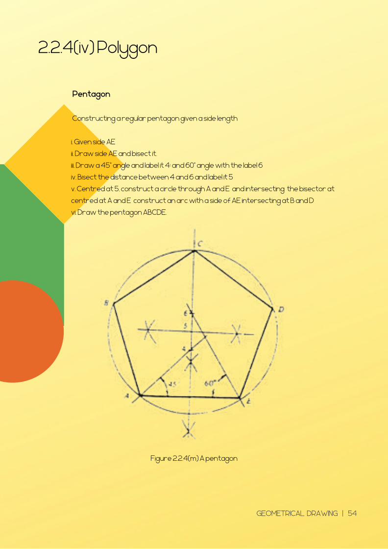
2.2.4(iv) Polygon
Pentagon
Constructing a regular pentagon given a side length
i. Given side AE
ii. Draw side AE and bisect it.
iii. Draw a 45° angle and label it 4; and 60° angle with the label 6
iv. Bisect the distance between 4 and 6 and label it 5
v. Centred at 5, construct a circle through A and E and intersecting the bisector at
centred at A and E construct an arc with a side of AE intersecting at B and D
vi. Draw the pentagon ABCDE.
Figure 2.2.4(m) A pentagon
GEOMETRICAL DRAWING | 54
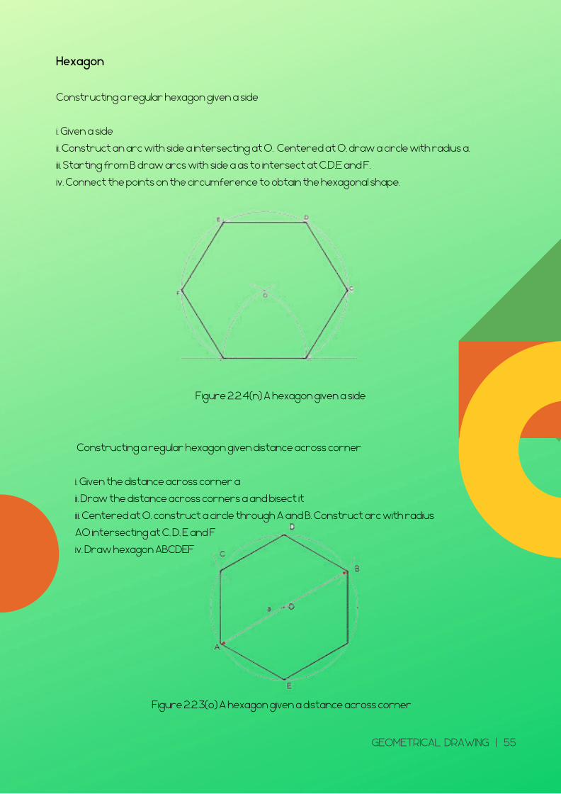
Hexagon
Constructing a regular hexagon given a side
i. Given a side
ii. Construct an arc with side a intersecting at O. Centered at O, draw a circle with radius a.
iii. Starting from B draw arcs with side a as to intersect at C,D,E and F.
iv. Connect the points on the circumference to obtain the hexagonal shape.
Constructing a regular hexagon given distance across corner
i. Given the distance across corner a
ii. Draw the distance across corners a and bisect it
iii. Centered at O, construct a circle through A and B. Construct arc with radius
AO intersecting at C, D, E and F
iv. Draw hexagon ABCDEF
Figure 2.2.4(n) A hexagon given a side
Figure 2.2.3(o) A hexagon given a distance across corner
GEOMETRICAL DRAWING | 55
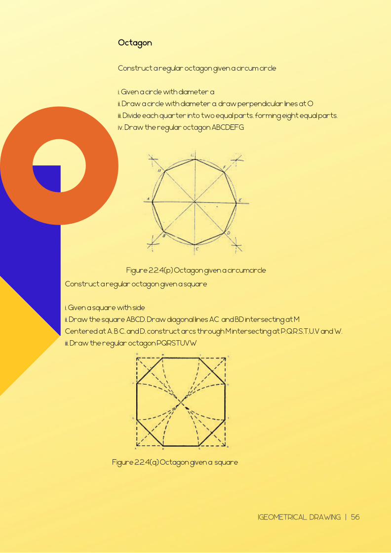
Octagon
Construct a regular octagon given a circum circle
i. Given a circle with diameter a
ii. Draw a circle with diameter a. draw perpendicular lines at O
iii. Divide each quarter into two equal parts, forming eight equal parts.
iv. Draw the regular octagon ABCDEFG
Construct a regular octagon given a square
i. Given a square with side
ii. Draw the square ABCD. Draw diagonal lines AC and BD intersecting at M
Centered at A, B C, and D, construct arcs through M intersecting at P,Q,R,S,T,U,V and W.
iii. Draw the regular octagon PQRSTUVW
Figure 2.2.4(p) Octagon given a circumcircle
Figure 2.2.4(q) Octagon given a square
IGEOMETRICAL DRAWING | 56
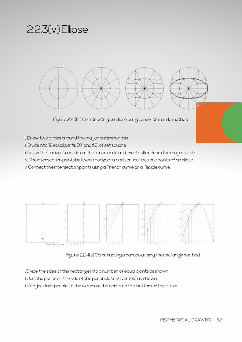
2.2.3(v) Ellipse
Figure 2.2.3(r) Constructing an ellipse using concentric circle method
i. Draw two circles around the major and minor axis
ii. Divide into 12 equal parts 30° and 60° of set square
iii. Draw the horizontal line from the minor circle and vertical line from the major circle
iv. The intersection points between horizontal and vertical lines are points of an ellipse.
v. Connect the intersection points using a French curve or a flexible curve.
Figure 2.2.4(s) Constructing a parabola using the rectangle method
i. Divide the sides of the rectangle into a number of equal points as shown.
ii. Join the points on the side of the parabola to V (vertex) as shown.
iii. Project lines parallel to the axis from the points on the bottom of the curve.
GEOMETRICAL DRAWING | 57

CHAPTER 2
GEOMETRICAL DRAWING | 58
TUTORIAL
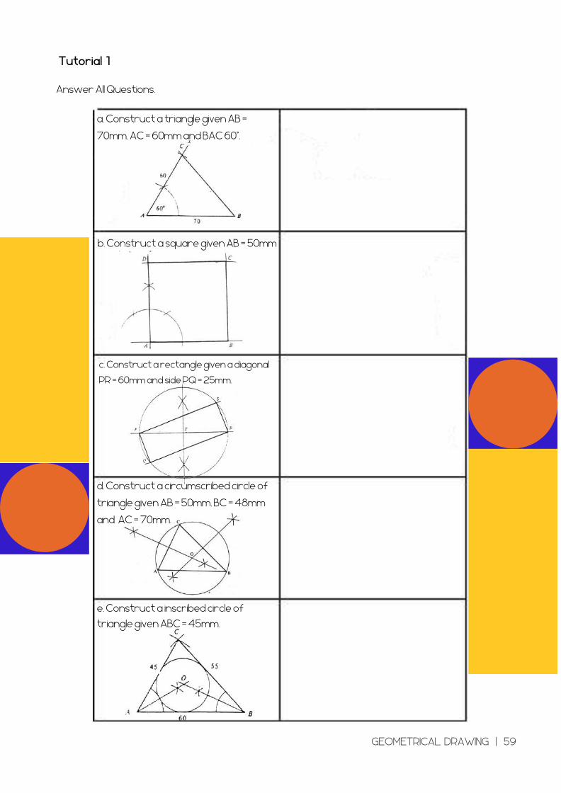
Tutorial 1
Answer All Questions.
a. Construct a triangle given AB =
70mm, AC = 60mm and BAC 60°.
b. Construct a square given AB = 50mm
c. Construct a rectangle given a diagonal
PR = 60mm and side PQ = 25mm.
d. Construct a circumscribed circle of
triangle given AB = 50mm, BC = 48mm
and AC = 70mm.
e. Construct a inscribed circle of
triangle given ABC = 45mm.
GEOMETRICAL DRAWING | 59
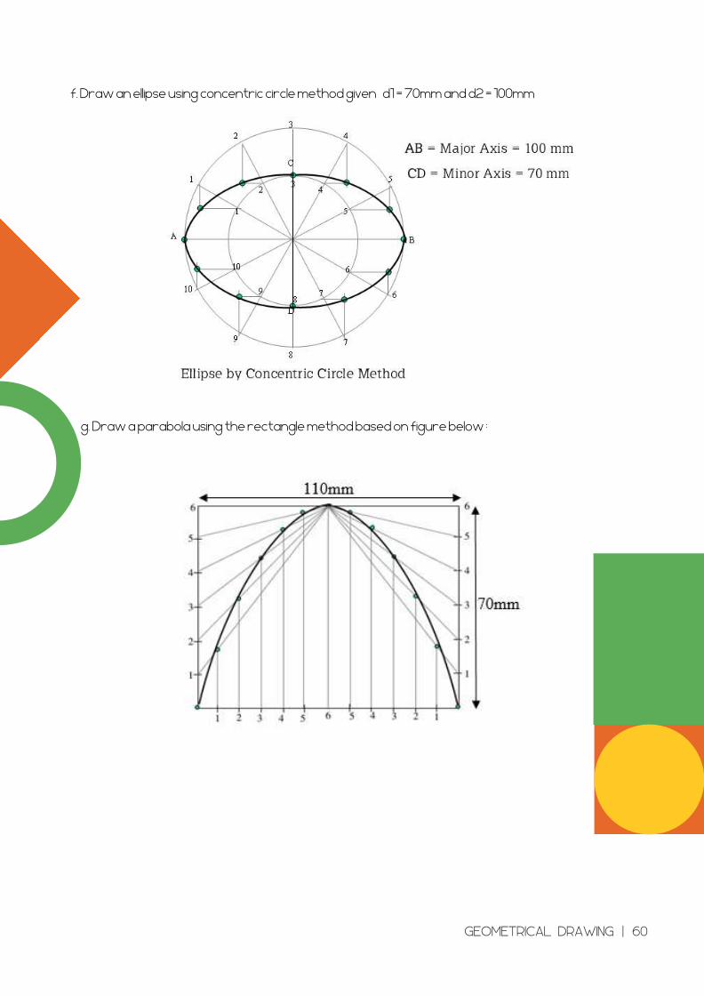
f. Draw an ellipse using concentric circle method given d1 = 70mm and d2 = 100mm
g. Draw a parabola using the rectangle method based on figure below :
GEOMETRICAL DRAWING | 60
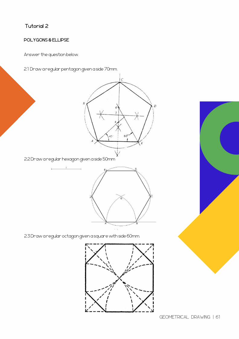
Tutorial 2
POLYGONS & ELLIPSE
Answer the question below.
2.1 Draw a regular pentagon given a side 70mm.
2.2 Draw a regular hexagon given a side 50mm
2.3 Draw a regular octagon given a square with side 60mm.
GEOMETRICAL DRAWING | 61
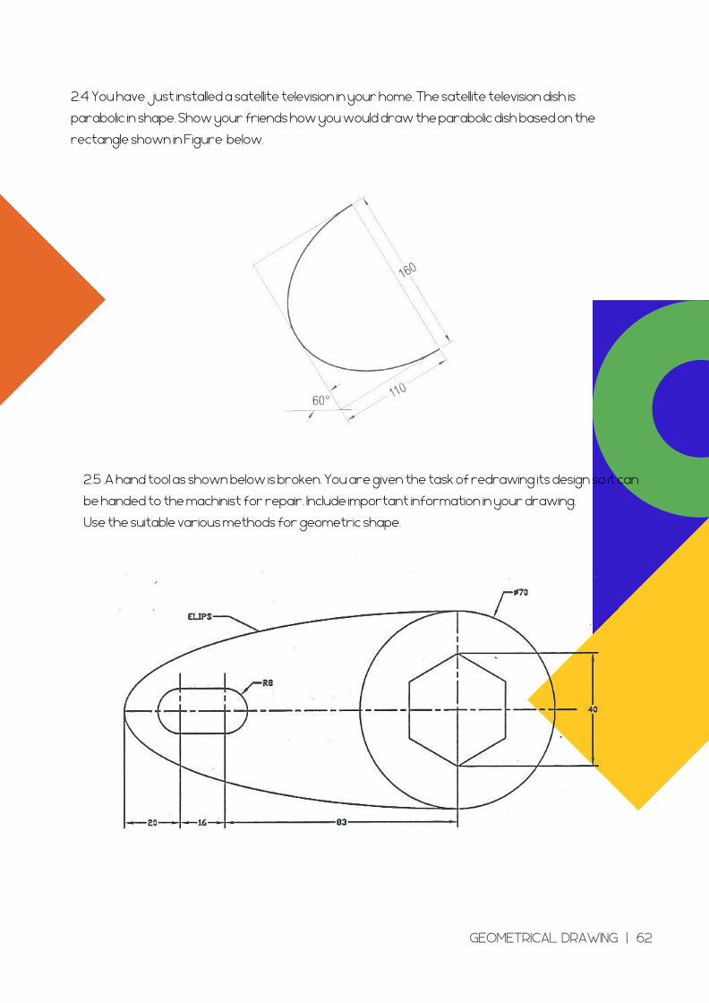
2.5 .A hand tool as shown below is broken. You are given the task of redrawing its design so it can
be handed to the machinist for repair. Include important information in your drawing.
Use the suitable various methods for geometric shape.
2.4 You have just installed a satellite television in your home. The satellite television dish is
parabolic in shape. Show your friends how you would draw the parabolic dish based on the
rectangle shown in Figure below.
GEOMETRICAL DRAWING | 62
CHAPTER 3 :
ORTHOGRAPHIC
PROJECTION AND
ISOMETRIC
Learning Outcomes
Explain an orthographic projection
Types of orthographic projection
Construct an orthographic projection drawing according to
standard required
Explain an isometric drawing
Construct an isometric drawing according to standard
required
ORTHOGRAPHIC PROJECTION AND ISOMETRIC | 63
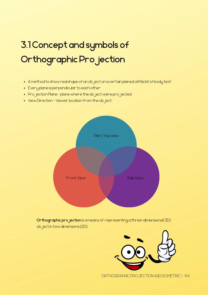
3.1 Concept and symbols of
Orthographic Projection
A method to show real shape of an object on a certain planed a little bit of body text
Every plane is perpendicular to each other
Projection Plane - plane where the object were projected
View Direction – Viewer location from the object
Orthographic projection is a means of representing a three-dimensional (3D)
object in two dimensions (2D).
Plan / top view
Side ViewFront View
ORTHOGRAPHIC PROJECTION AND ISOMETRIC | 64
3.2 Types of orthographic Projection
First Angle
Third Angle
ORTHOGRAPHIC PROJECTION AND ISOMETRIC | 65
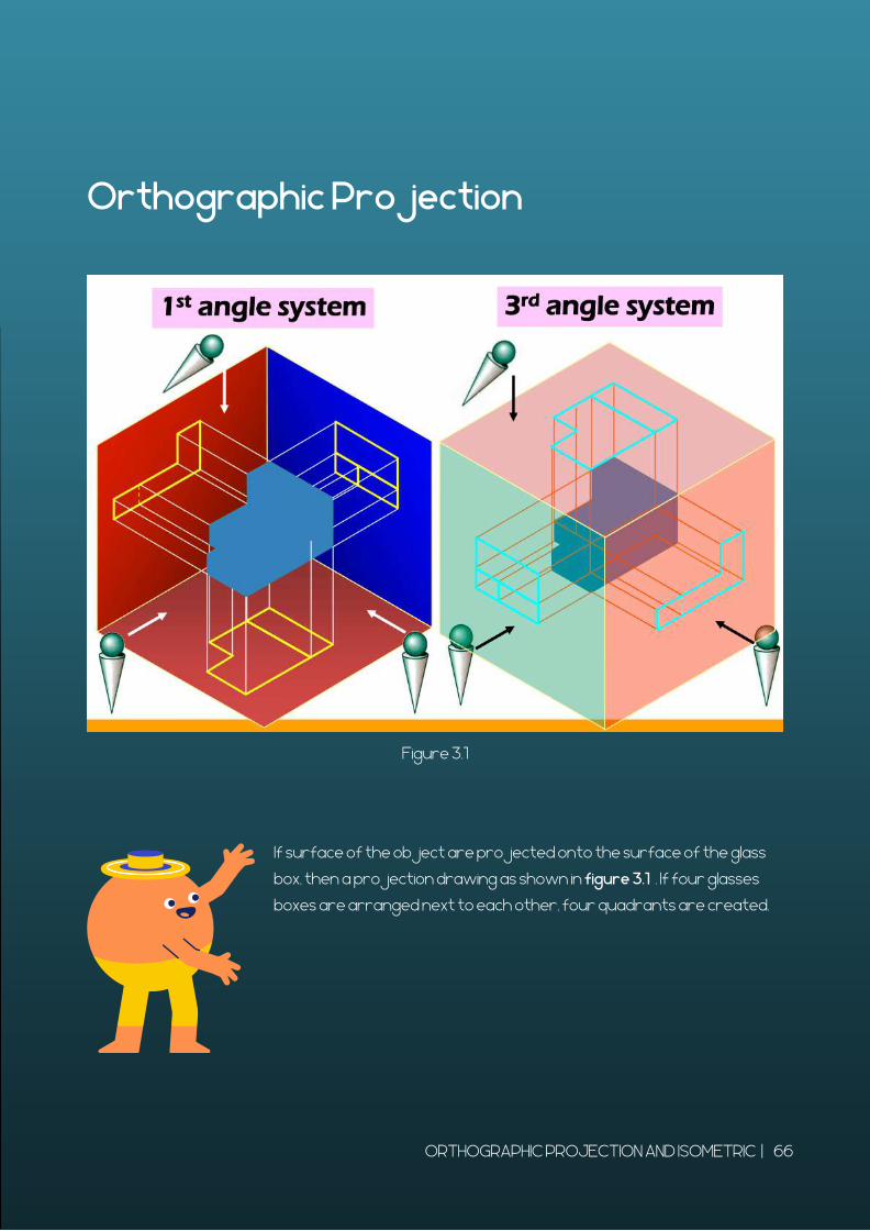
Orthographic Projection
If surface of the object are projected onto the surface of the glass
box, then a projection drawing as shown in figure 3.1 . If four glasses
boxes are arranged next to each other, four quadrants are created.
Figure 3.1
ORTHOGRAPHIC PROJECTION AND ISOMETRIC | 66
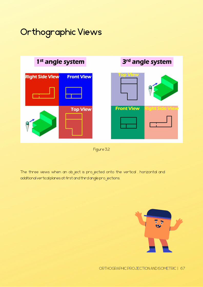
Orthographic Views
The three views when an object is projected onto the vertical , horizontal and
additional vertical planes at first and third angle projections.
Figure 3.2
ORTHOGRAPHIC PROJECTION AND ISOMETRIC | 67
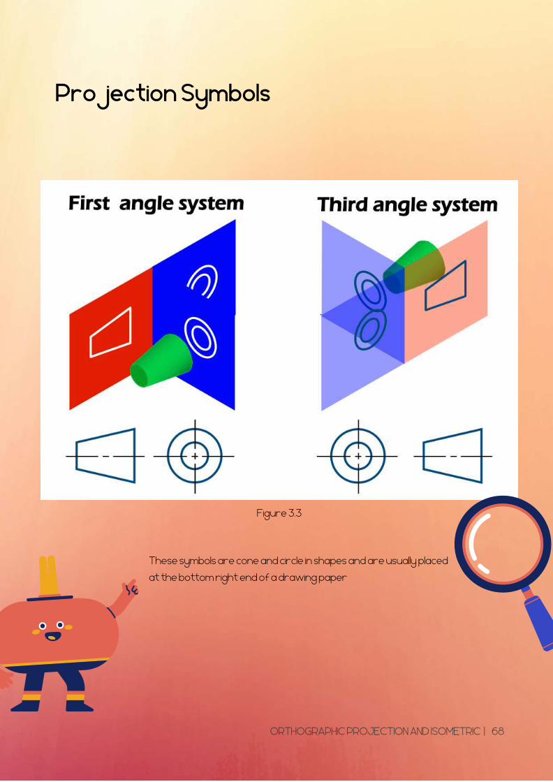
Projection Symbols
These symbols are cone and circle in shapes and are usually placed
at the bottom right end of a drawing paper
Figure 3.3
ORTHOGRAPHIC PROJECTION AND ISOMETRIC | 68
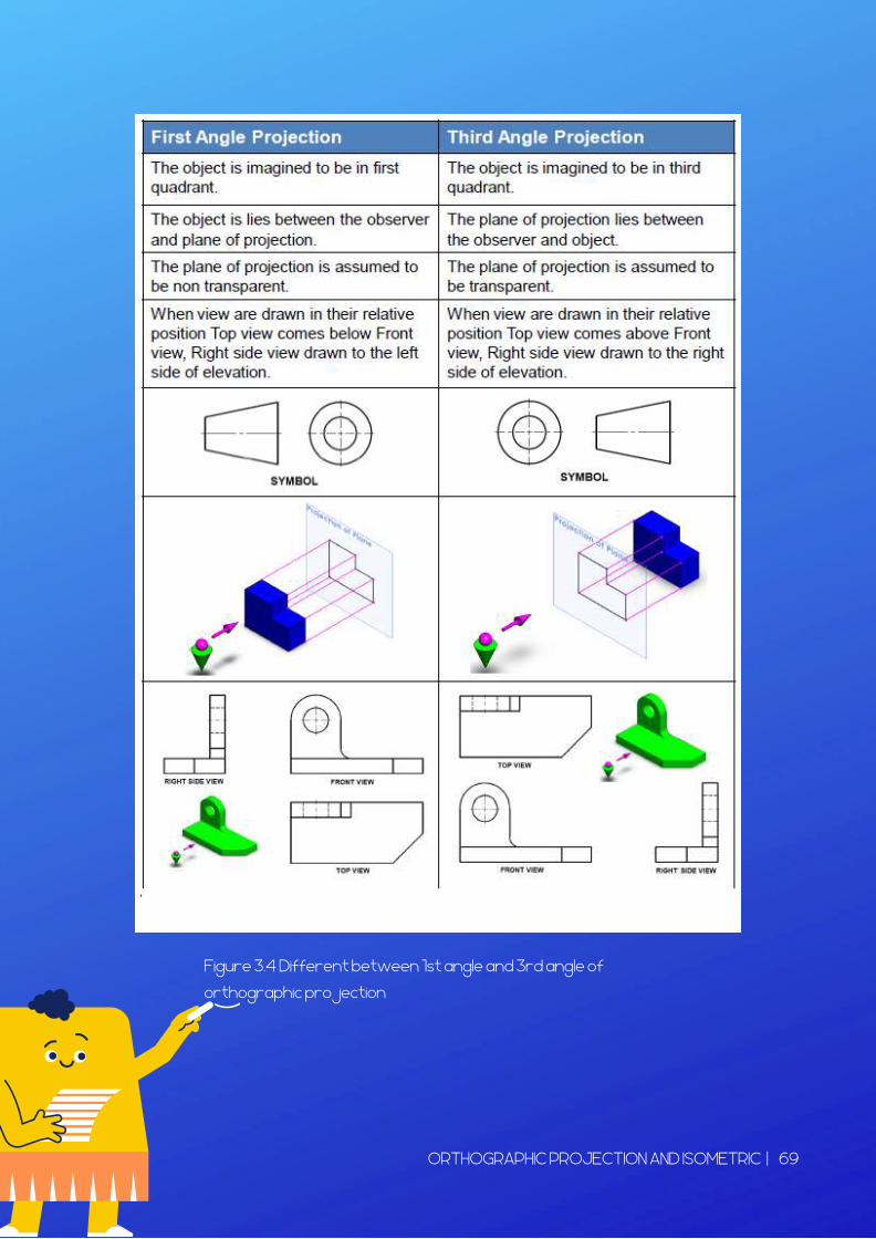
Figure 3.4 Different between 1st angle and 3rd angle of
orthographic projection
ORTHOGRAPHIC PROJECTION AND ISOMETRIC | 69
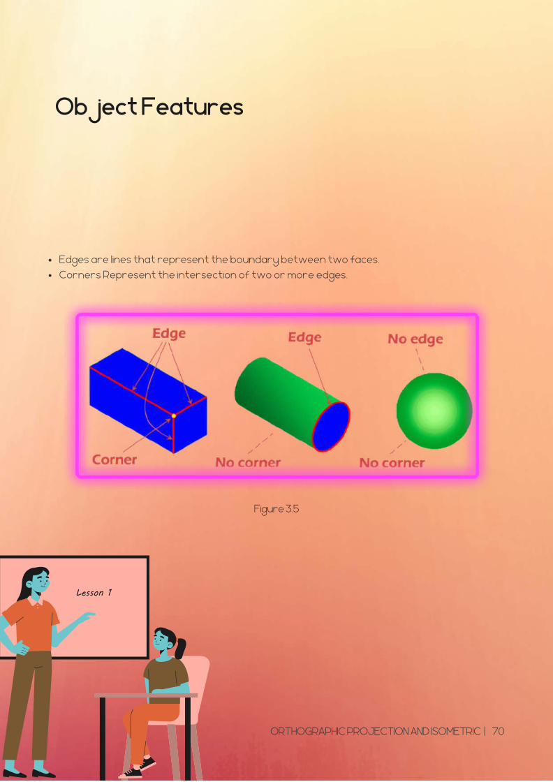
Object Features
Edges are lines that represent the boundary between two faces.
Corners Represent the intersection of two or more edges.
Figure 3.5
ORTHOGRAPHIC PROJECTION AND ISOMETRIC | 70
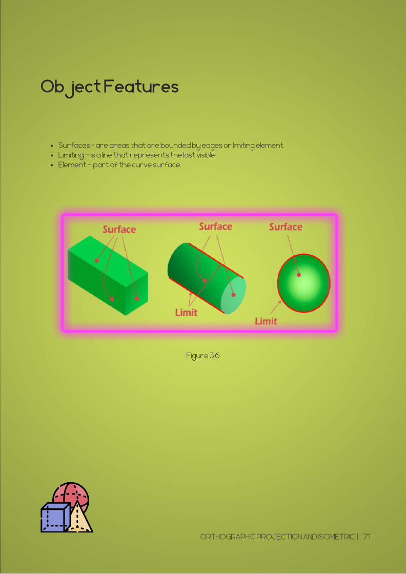
Object Features
Surfaces - are areas that are bounded by edges or limiting element.Limiting - is a line that represents the last visibleElement - part of the curve surface.
Figure 3.6
ORTHOGRAPHIC PROJECTION AND ISOMETRIC | 71
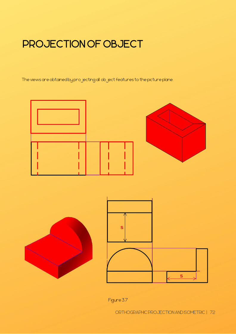
PROJECTION OF OBJECT
The views are obtained by projecting all object features to the picture plane.
Figure 3.7
ORTHOGRAPHIC PROJECTION AND ISOMETRIC | 72
TECHNIQUES FORSPACING OUTDRAWING
Selection of the front viewSelection of the adjacent view Method to space out drawing
Things to consider :
ORTHOGRAPHIC PROJECTION AND ISOMETRIC | 73
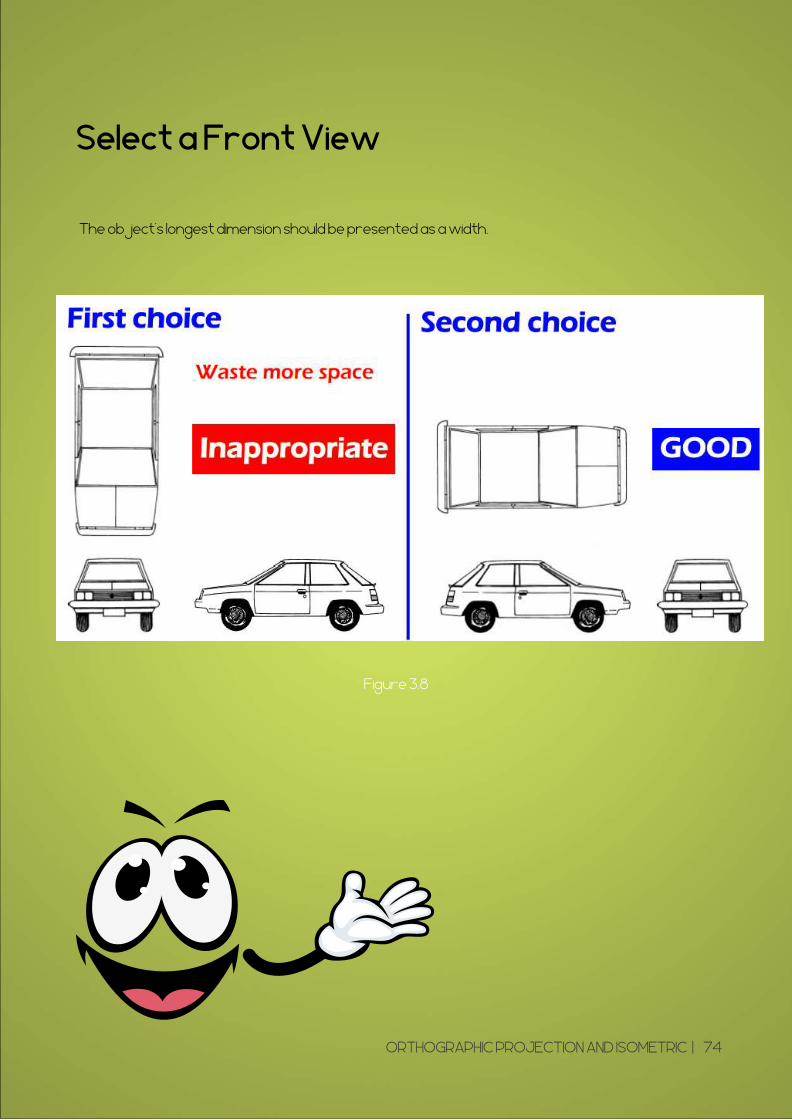
Select a Front View
The object’s longest dimension should be presented as a width.
Figure 3.8
ORTHOGRAPHIC PROJECTION AND ISOMETRIC | 74
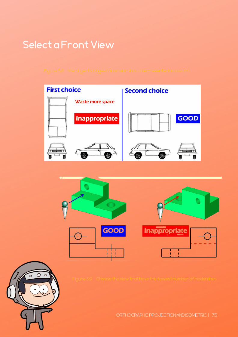
Select a Front View
The object’s longest dimension should be presented as a width.
Choose the view that have the fewest number of hidden lines.
Figure 3.8
Figure 3.9
ORTHOGRAPHIC PROJECTION AND ISOMETRIC | 75
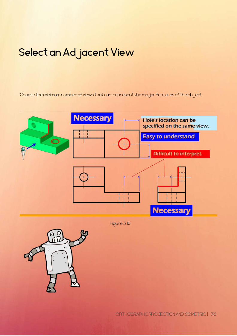
Select an Adjacent View
Choose the minimum number of views that can represent the major features of the object.
Figure 3.10
ORTHOGRAPHIC PROJECTION AND ISOMETRIC | 76
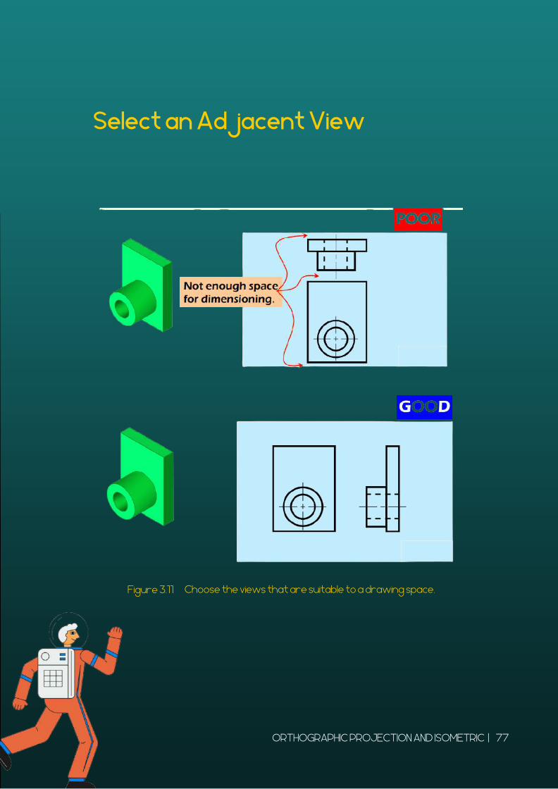
Select an Adjacent View
Choose the views that are suitable to a drawing space.Figure 3.11
ORTHOGRAPHIC PROJECTION AND ISOMETRIC | 77
Method to space out drawing
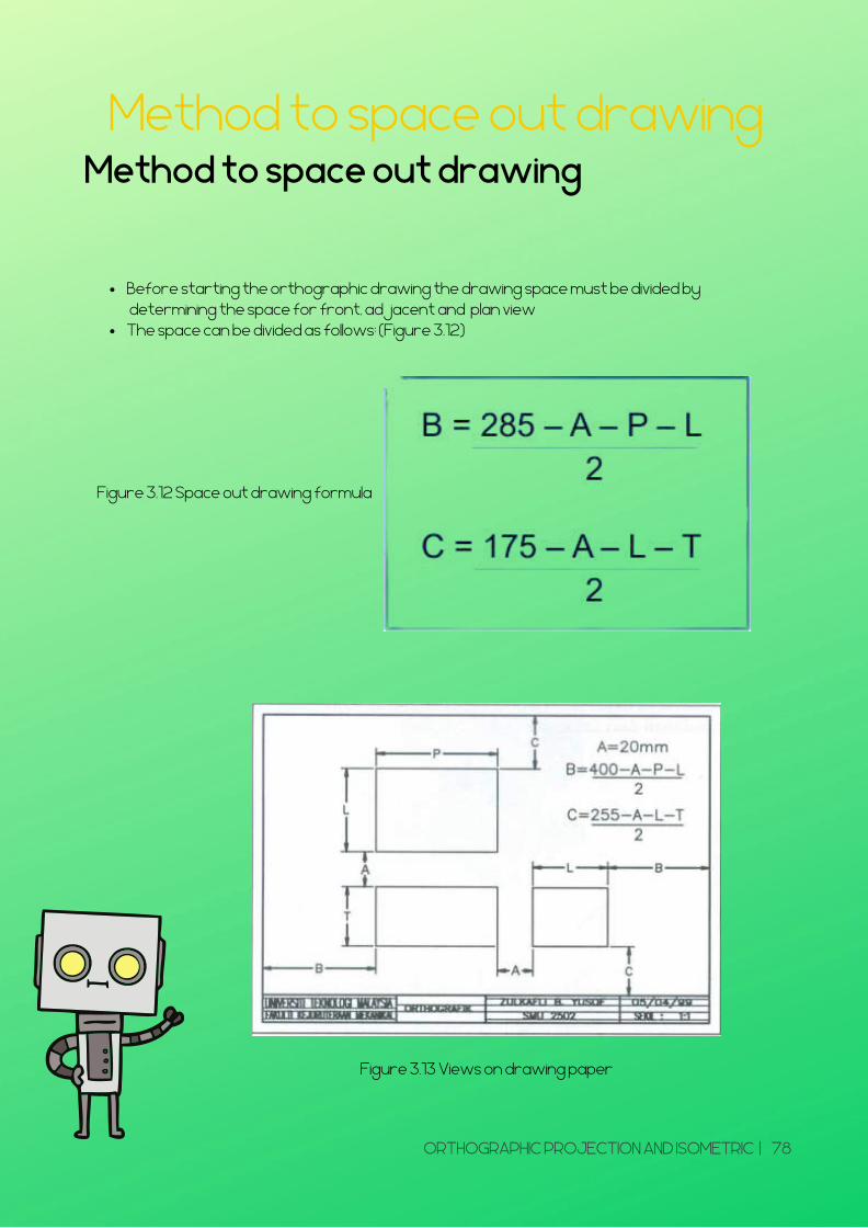
Before starting the orthographic drawing the drawing space must be divided by determining the space for front, adjacent and plan view The space can be divided as follows: (Figure 3.12)
Method to space out drawing
Figure 3.12 Space out drawing formula
Figure 3.13 Views on drawing paper
ORTHOGRAPHIC PROJECTION AND ISOMETRIC | 78
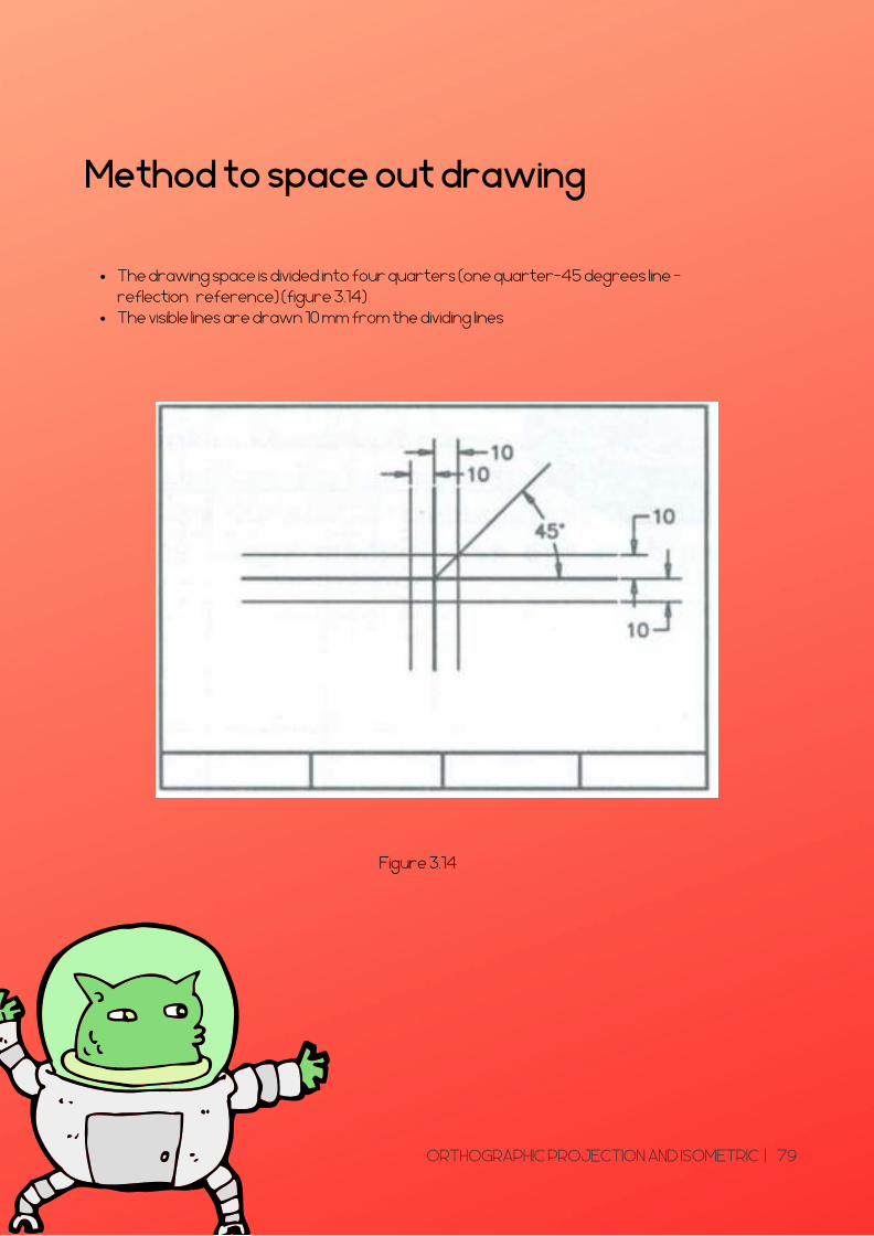
The drawing space is divided into four quarters (one quarter-45 degrees line –reflection reference) (figure 3.14)The visible lines are drawn 10 mm from the dividing lines
Method to space out drawing
Figure 3.14
ORTHOGRAPHIC PROJECTION AND ISOMETRIC | 79
Method to space out drawing
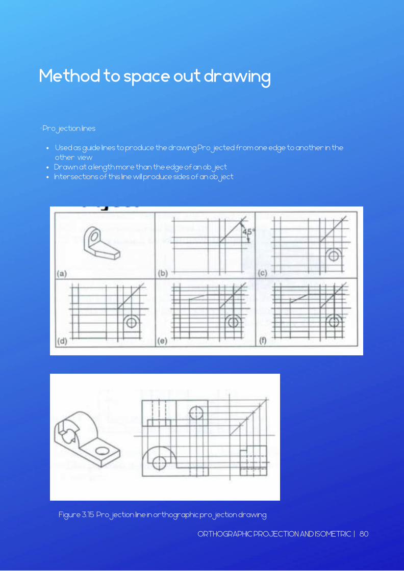
Used as guide lines to produce the drawing Projected from one edge to another in the
Drawn at a length more than the edge of an objectIntersections of this line will produce sides of an object
• Projection lines
other view
Figure 3.15 Projection line in orthographic projection drawing
ORTHOGRAPHIC PROJECTION AND ISOMETRIC | 80
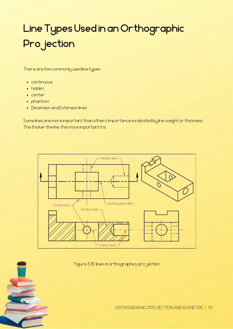
Line Types Used in an Orthographic
Projection
continuous
hidden
center
phantom
Dimension and Extension lines
There are five commonly used line types;
Some lines are more important than others. Importance is indicated by line weight or thickness.
The thicker the line, the more important it is.
Figure 3.16 lines in orthographics projection
ORTHOGRAPHIC PROJECTION AND ISOMETRIC | 81

WRITING STEPS
1. Select the necessary views
2. Layout the views.
3. Project the views.
4. Dimension the views.
ORTHOGRAPHIC PROJECTION AND ISOMETRIC | 82
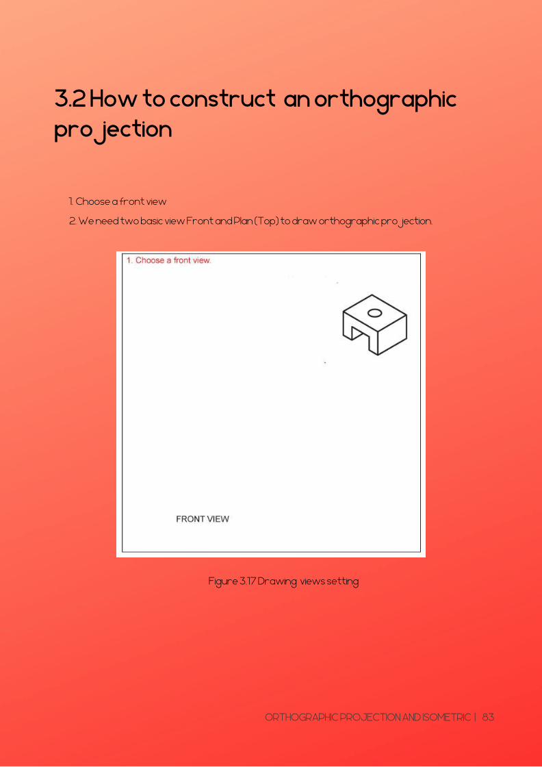
3.2 How to construct an orthographicprojection
Choose a front view1.
2. We need two basic view Front and Plan (Top) to draw orthographic projection.
Figure 3.17 Drawing views setting
ORTHOGRAPHIC PROJECTION AND ISOMETRIC | 83
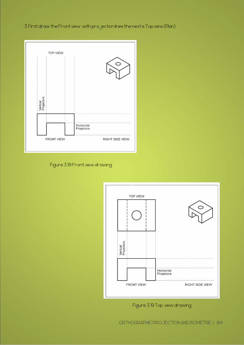
3. First draw the Front view with projection lines the next is Top view (Plan)
Figure 3.18 Front view drawing
Figure 3.19 Top view drawing
ORTHOGRAPHIC PROJECTION AND ISOMETRIC | 84

4. Draw a 45 degree projector off the front view.
5. Project over from the top (Plan) view and down.
Figure 3.20 Front and top view drawing with 45 degree line
ORTHOGRAPHIC PROJECTION AND ISOMETRIC | 85
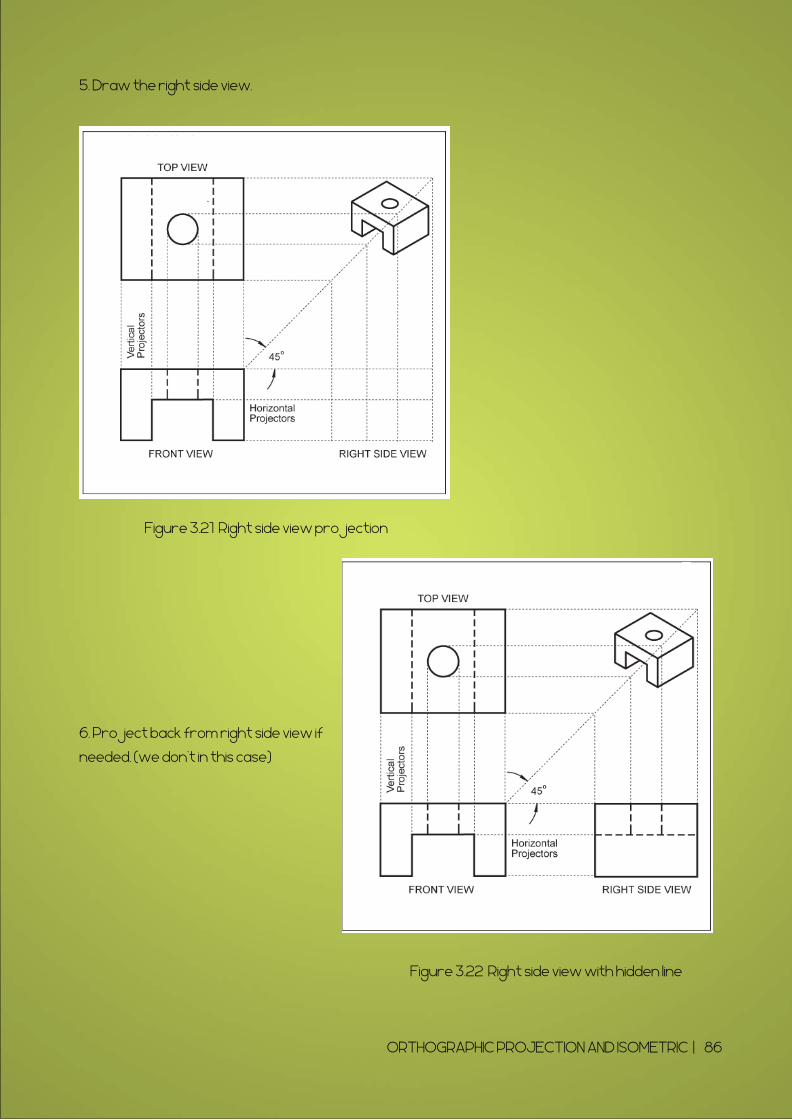
5. Draw the right side view.
6. Project back from right side view if
needed. (we don't in this case)
Figure 3.21 Right side view projection
Figure 3.22 Right side view with hidden line
ORTHOGRAPHIC PROJECTION AND ISOMETRIC | 86
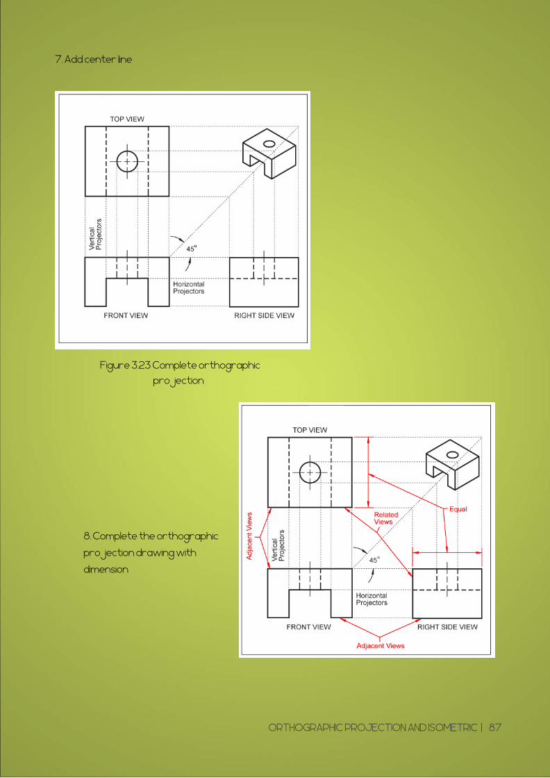
7. Add center line
8. Complete the orthographic
projection drawing with
dimension
Figure 3.23 Complete orthographic
projection
ORTHOGRAPHIC PROJECTION AND ISOMETRIC | 87
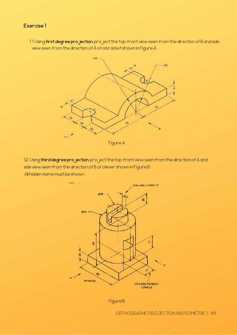
Exercise 1
1 Using first degree projection, project the top, front view seen from the direction of B and side
view seen from the direction of A of a bracket shown in Figure A
1.
Figure A
1.2 Using third degree projection, project the top, front view seen from the direction of A and
side view seen from the direction of B of a lever shown in Figure B
All hidden items must be shown.
Figure B
ORTHOGRAPHIC PROJECTION AND ISOMETRIC | 88
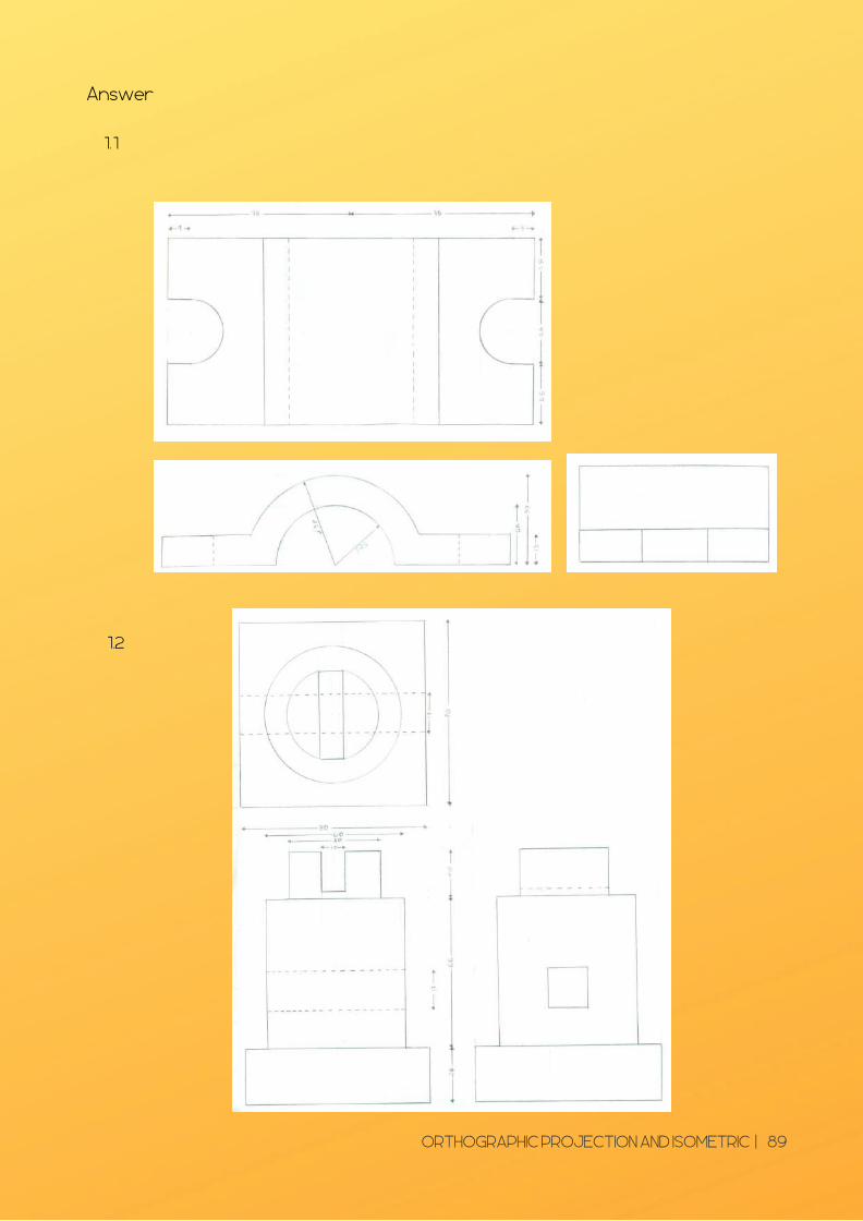
Answer
11.
1.2
ORTHOGRAPHIC PROJECTION AND ISOMETRIC | 89

3 Using first degree projection, project the top, front view seen from the direction of B and
side view seen from the direction of A of a block shown in Figure C.
1.
1.4 . Using third degree projection, project the top, front view seen from the direction of A and
side view seen from the direction of B of a guide block shown in Figure D
All hidden items must be shown.
Figure C
Figure D
ORTHOGRAPHIC PROJECTION AND ISOMETRIC | 90

3.3 ISOMETRIC
DRAWING A method for visually representing three-dimensional
objects with width, height and depth measurement in
technical and engineering drawings.
ORTHOGRAPHIC PROJECTION AND ISOMETRIC | 91
Different Orthographic projection and
Isometric view
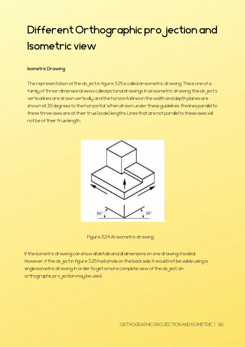
Isometric Drawing
The representation of the object in figure 3.25 is called an isometric drawing. This is one of a
family of three-dimensional views called pictorial drawings. In an isometric drawing, the object's
vertical lines are drawn vertically, and the horizontal lines in the width and depth planes are
shown at 30 degrees to the horizontal. When drawn under these guidelines, the lines parallel to
these three axes are at their true (scale) lengths. Lines that are not parallel to these axes will
not be of their true length.
Figure 3.24 An isometric drawing
If the isometric drawing can show all details and all dimensions on one drawing, it is ideal.
However, if the object in figure 3.25 had a hole on the back side, it would not be visible using a
single isometric drawing. In order to get a more complete view of the object, an
orthographic projection may be used.
ORTHOGRAPHIC PROJECTION AND ISOMETRIC | 92

Orthographic or Multiview Drawing
Imagine that you have an object suspended by transparent threads inside a glass box, as in figure
3.26.
Figure 3.25 The block suspended in a glass box
Then draw the object on each of three faces as seen from that direction. Unfold the box
(figure 3.27) and you have the three views. We call this an "orthographic" or "multiview"
drawing.
Figure 3.26 The creation of an orthographic multiview drawing
ORTHOGRAPHIC PROJECTION AND ISOMETRIC | 93

Figure 3.27 shows how the three views appear on a piece of paper after unfolding the box.
Three views are not always necessary; we need only as many views as are required to describe
the object fully. For example, some objects need only two views, while others need four.
The circular object in figure 3.29 requires only two views.
Figure 3.28 An object needing only two orthogonal views
ORTHOGRAPHIC PROJECTION AND ISOMETRIC | 94

3.4 Construct an isometric drawing
according to standard required
The example below Figure 3.29 has been drawn with a 30 degree set square. Designs are always
drawn at 30 degree in isometric projection. It is vital that drawing equipment such as T - square
and 30/60 set square are use carefully.
Figure 3.29 How to draw an Isometric axis
Isometric Axes : The lines AB, AD and AE meeting at a point A and making an angle of 120° with
each other are termed ‘isometric axes’.
Isometric Lines:The lines parallel to the isometric axes are termed isometric lines. The lines CD, CB
etc are examples of isometric lines.
Non-isometric Lines:The lines which are not parallel to isometric axes are termed non- isometric
lines. The BD is an example.
Isometric Planes: The planes representing the faces of the rectangular prism as well as other
planes parallel to these planes are termed isometric planes.
Isometric scale: Isometric projection is drawn using isometric scale, which converts true lengths
into isometric lengths (foreshortened).
Figure 3.30 An Isometric axis
ORTHOGRAPHIC PROJECTION AND ISOMETRIC | 95

3.41 Box Method
The isometric projection of solids like cube, square and rectangular prisms are drawn directly
when their edges are parallel to the three isometric axes. The isometric projection of all other
types of prisms and cylinders are drawn by enclosing them in a rectangular box. This method is
called Box method.
Example :
Make an Isometric Drawing with corner A at the bottom.
Figure 3.31 Example of orthographic drawing
ORTHOGRAPHIC PROJECTION AND ISOMETRIC | 96
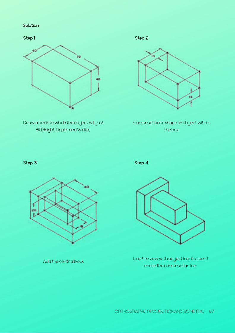
Solution :
Step 1
Draw a box into which the object will just
fit (Height, Depth and Width)
Step 2
Construct basic shape of object within
the box
Step 3
Add the central block
Step 4
Line the view with object line. But don't
erase the construction line.
ORTHOGRAPHIC PROJECTION AND ISOMETRIC | 97
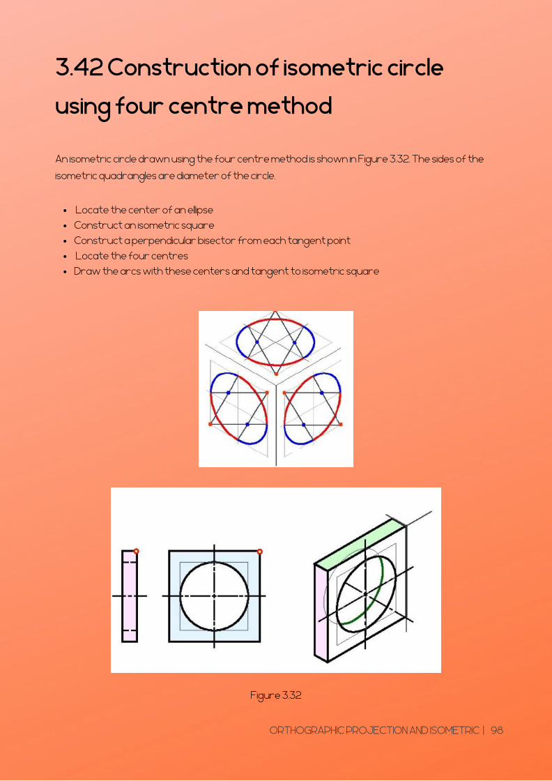
3.42 Construction of isometric circle
using four centre method
An isometric circle drawn using the four centre method is shown in Figure 3.32. The sides of the
isometric quadrangles are diameter of the circle.
Figure 3.32
�Locate the center of an ellipse �
Construct an isometric square �
Construct a perpendicular bisector from each tangent point �
Locate the four centres �
Draw the arcs with these centers and tangent to isometric square
ORTHOGRAPHIC PROJECTION AND ISOMETRIC | 98
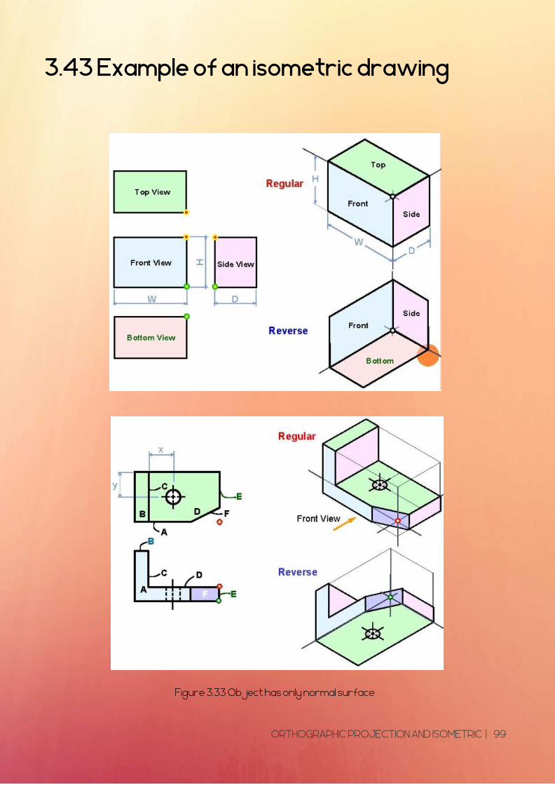
3.43 Example of an isometric drawing
Figure 3.33 Object has only normal surface
Figure 3.34 Object has incline surface
ORTHOGRAPHIC PROJECTION AND ISOMETRIC | 99

Figure 3.34Object has incline surface
ORTHOGRAPHIC PROJECTION AND ISOMETRIC | 100
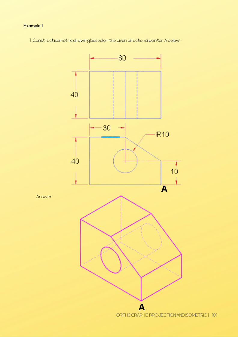
Example 1
Construct isometric drawing based on the given directional pointer A below : 1.
Answer A
A ORTHOGRAPHIC PROJECTION AND ISOMETRIC | 101
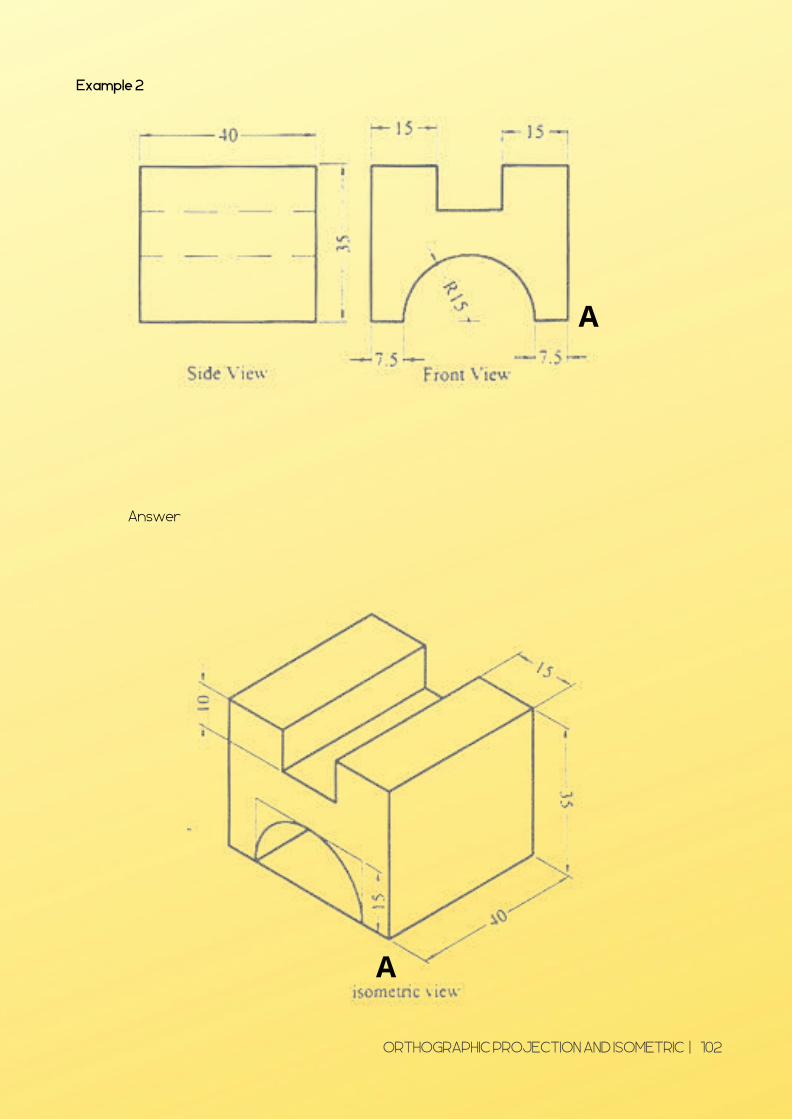
Example 2
Answer
A
A
ORTHOGRAPHIC PROJECTION AND ISOMETRIC | 102

Example 3
Answer
A
20
ORTHOGRAPHIC PROJECTION AND ISOMETRIC | 103

TUTORIAL
CHAPTER 3
ORTHOGRAPHIC PROJECTION AND ISOMETRIC | 104

TUTORIAL 1
1 Construct an isometric drawing, complete with dimensions, of one of the parts shown and
based on the given directional pointer A below.
a) b)
c) d)
A
ORTHOGRAPHIC PROJECTION AND ISOMETRIC | 105

TUTORIAL 2
ORTHOGRAPHIC PROJECTION AND ISOMETRIC | 106
ORTHOGRAPHIC DRAWING
Answer all questions.
1. Draw three views of the following components in figure 1 with third angle projection. Show
hidden detail where necessary and fully dimensions your drawing. (mm)
ISOMETRIC DRAWING
2. Construct isometric drawing in figure 2 based on the given directional pointer O below with
scale 2 : 1. All dimensions are in mm. Show hidden detail where necessary and fully dimensions
on your drawing.

Answer
2.
ORTHOGRAPHIC PROJECTION AND ISOMETRIC | 107
1.

a) Front view (from X)
b) Top View
c) Side View
3 The pictorial of a mechanics part is given I the figure. Draw the following views :
4. Draw the isometric view of the given views.
ORTHOGRAPHIC PROJECTION AND ISOMETRIC | 108

5. Construct isometric drawings based on the given front and top directional views below. Use
point A as a guide.
A A
A
A A A
A A
ORTHOGRAPHIC PROJECTION AND ISOMETRIC | 109

CHAPTER 4
GEOMETRICGEOMETRICDIMENSIONING ANDDIMENSIONING AND
TOLERANCETOLERANCE
Geometric dimensioning fortechnical drawingThe tolerance for technicaldrawing
GEOMETRIC DIMENSIONING TOLERANCE| 110

Before an object can be built, complete information about both the size and shape of
the object must be available. The exact shape of an object is communicated through
orthographic drawings, which are developed following standard drawing practices. The
process of adding size information to a drawing is known as dimensioning the drawing.
Geometrics is the science of specifying and tolerancing the shapes and locations of
features on objects. Once the shape of a part is defined with an orthographic
drawings, the size information is added also in the form of dimensions. �
Dimensioning a drawing also identifies the tolerance (or accuracy) required for each
dimension.
�If a part is dimensioned properly, then the intent of the designer is clear to both the
person making the part and the inspector checking the part. �
A fully defined part has three elements: graphics, dimensions, and words (notes).
DIMENSIONING
GEOMETRIC DIMENSIONING TOLERANCE| 111

SIZE AND LOCATION DIMENSIONS
A well dimensioned part will communicate the size and location requirements for
each feature. Communications is the fundamental purpose of dimensions.
� Parts are dimensioned based on two criteria:
� Basic size and locations of the features.
Details of a part's construction and for manufacturing.
UNIT OF MEASURE
� On a drawing used in American industry, all dimensions are in inches, unless otherwise
� Most countries outside of the United States use the metric system of measure, or the i
�The SI system is being used more in the United States because of global trade and
Occasionally, a company will used dual dimensioning, that is, both metric and English
measurements on a drawing. �
Angular dimensions are shown either in decimal degrees or in degrees, minutes, and seconds.
stated.
international system of units (SI), which is based on the meter.
multinational company affiliations.
Figure 4.1 Example unit of measure
GEOMETRIC DIMENSIONING TOLERANCE| 112

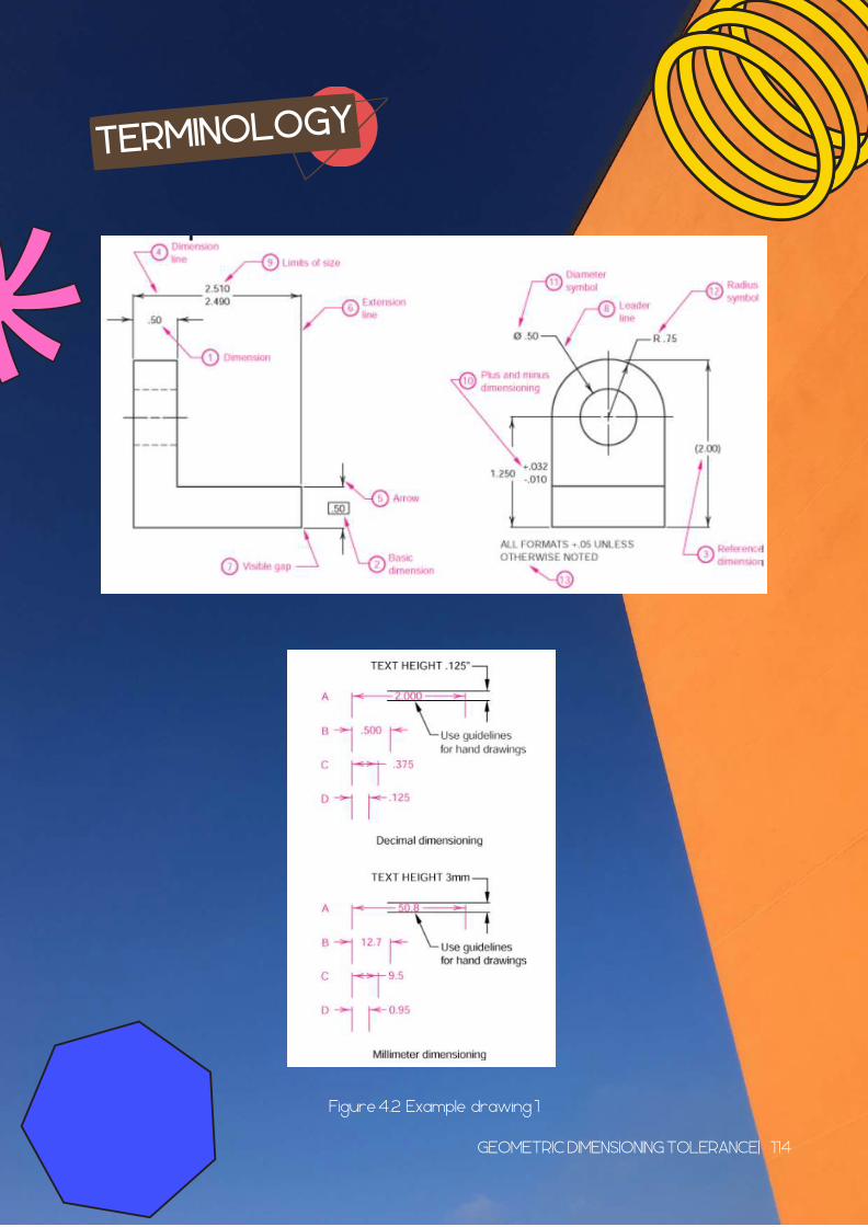
TERMINOLOGY
Dimension is the numerical value that defines the size or geometric characteristic of a
feature.
�Basic dimension is the numerical value defining the theoretically exact size of a feature.
�Reference dimension is the numerical value enclosed in parentheses provided for
information only and is not used in the fabrication of the part.
Dimension line is the thin solid line which shows the extent and direction of a dimension. �
Arrows are placed at the ends of dimension lines to show the limits of the dimension. �
Extension line is the thin solid line perpendicular to a dimension line indicating which feature is
associated with the dimension.
Leader line is the thin solid line used to indicate the feature with which a dimension, note, or
symbol is associated. �
Tolerance is the amount a particular dimension is allowed to vary. �
Plus and minus dimensioning is the allowable positive and negative variance from the
dimension specified
Diameter symbol is the symbol which is placed preceding a numerical value indicating that the
associated dimension shows the diameter of a circle. The symbol used is the Greek letter phi. �
Radius symbol is the symbol which is placed preceding a numerical value indicating that the
associated dimension shows the radius of a circle. The radius symbol used is the capital letter
R.
Datum is the theoretically exact point used as a reference for tabular dimensioning.
GEOMETRIC DIMENSIONING TOLERANCE| 113
TERMINOLOGY
Figure 4.2 Example drawing 1
GEOMETRIC DIMENSIONING TOLERANCE| 114
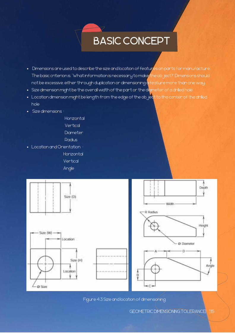
BASIC CONCEPT
�Dimensions are used to describe the size and location of features on parts for manufacture.
The basic criterion is, "What information is necessary to make the object?" Dimensions should
not be excessive, either through duplication or dimensioning a feature more than one way.
Size dimension might be the overall width of the part or the diameter of a drilled hole. �
Location dimension might be length from the edge of the object to the center of the drilled
hole
�Size dimensions �:
Location and Orientation � :
Horizontal �
Vertical �
Diameter �
Radius �
Horizontal �
Vertical �
Angle
Figure 4.3 Size and location of dimensioning
GEOMETRIC DIMENSIONING TOLERANCE| 115
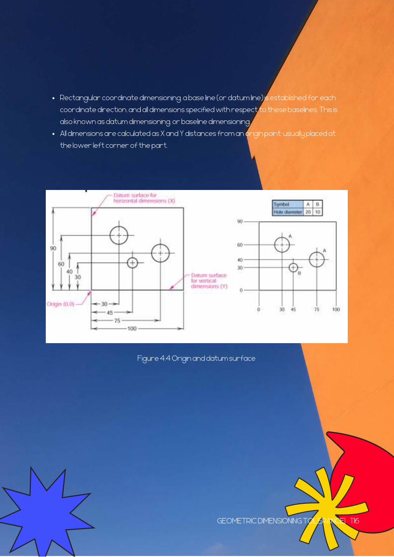
Rectangular coordinate dimensioning, a base line (or datum line) is established for each
coordinate direction, and all dimensions specified with respect to these baselines. This is
also known as datum dimensioning, or baseline dimensioning.
All dimensions are calculated as X and Y distances from an origin point, usually placed at
the lower left corner of the part.
Figure 4.4 Origin and datum surface
GEOMETRIC DIMENSIONING TOLERANCE| 116
PLACEMENT OF DIMENSION
RECOMMENDED PRACTICE
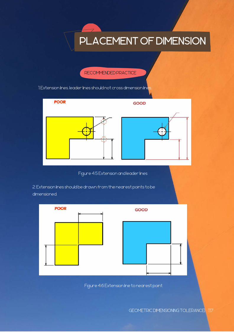
Extension lines, leader lines should not cross dimension lines.1.
Figure 4.5 Extension and leader lines
2. Extension lines should be drawn from the nearest points to be
dimensioned.
Figure 4.6 Extension line to nearest point
GEOMETRIC DIMENSIONING TOLERANCE| 117
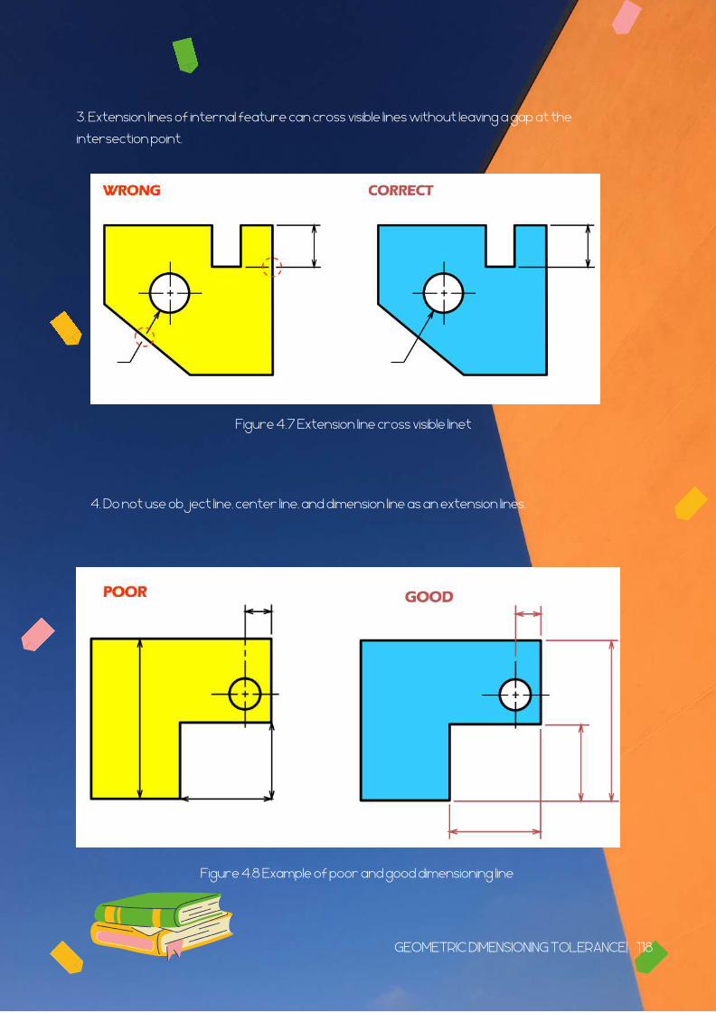
3. Extension lines of internal feature can cross visible lines without leaving a gap at the
intersection point.
Figure 4.7 Extension line cross visible linet
4. Do not use object line, center line, and dimension line as an extension lines.
Figure 4.8 Example of poor and good dimensioning line
GEOMETRIC DIMENSIONING TOLERANCE| 118

5. Avoid dimensioning hidden lines and place dimensions outside the view, unless placing them
inside improve the clarity..
Figure 4.9 Dimension line outside the view
6. Apply the dimension to the view that clearly show the shape or features of an object.
Figure 4.10 Dimension clearly view
GEOMETRIC DIMENSIONING TOLERANCE| 119

7. Dimension lines should be lined up and grouped together as much as possible.
Figure 4.11 Dimension group together
.8. Do not repeat a dimension.
Figure 4.12 Do not repeat dimension
GEOMETRIC DIMENSIONING TOLERANCE| 120

TOLERANCE
Tolerance is the total amount a dimension may vary and is the difference between the upper
(maximum) and lower (minimum) limits.
�Tolerances are used to control the amount of variation inherent in all manufactured parts. In
particular, tolerances are assigned to mating parts in an assembly.
Tolerances are used in production drawings to control the manufacturing process more
accurately and control the variation between parts.
What is tolerance in technical drawing?
Tolerancing and Interchangeability
An interchangeable part is simply a mass produced part (a replacement part).
A single value dimension (1.00) now becomes a range of values (.995 - 1.005).
A tolerance is the amount of size variation permitted. You can choose a tolerance that
specifies a large or small variation.
Tolerance = max. size - min size
It is necessary because it is impossible to manufacture parts without some variation. The
stated limits are a form of quality control.
the design intent (end use) of the part
cost
how it is manufactured
experience
What is interchangeability?
How is a feature on an interchangeable part dimensioned?
Why do we want a part’s size to be controlled by two limits?
Choosing a tolerance for your design.
Specify a tolerance with whatever degree of accuracy that is required for the design to work
properly. Choose a tolerance that is not unnecessarily accurate or excessively inaccurate.
Choosing the correct tolerance for a particular application depends on:
GEOMETRIC DIMENSIONING TOLERANCE| 121

Tolerancing Standards
American National Standards Institute (ANSI) / (ASME)
International Standards Organization (ISO).
Standards are needed ...
to make it possible to manufacture parts at different times and in different places that still
assemble properly.
establish dimensional limits for parts that are to be interchangeable.
Standard agencies
The two most common standards agencies are;
Figure 4.13 Tolerance in technical drawing
GEOMETRIC DIMENSIONING TOLERANCE| 122

Types of tolerances
bilateral tolerances,
unilateral tolerances
limit tolerances
single limit tolerances.
There are 4 different types of tolerances .
Figure 4.14 Types of Tolerance
Limit Tolerances show both a maximum and minimum dimension allowable for the feature.
A Single Limit Tolerance only defines one limit dimension, normally either the maximum or
minimum value for a feature or dimension.
The Bilateral Tolerance shows the nominal dimension (0.212) and the allowable tolerance in
either direction + .001.
The Unilateral Tolerance shows the nominal dimension (0.212) and a tolerance in only one
direction +0.001.
GEOMETRIC DIMENSIONING TOLERANCE| 123

GD&T SYMBOLS FOR
TOLERANCING
One of the benefits of GD&T is the usage of common symbols that are used to further tolerance
a part all of the different characteristics of a component that can be critical.
Below is a table showing the 14 standard geometric tolerance symbols used in geometric
tolerancing as defined by ASME Y14.5. These geometric tolerances fall into one of five categories –
Form, Location, Orientation, Profile & Runout.
Figure 4.1.5 Standard geometric tolerance symbols used in geometric
GEOMETRIC DIMENSIONING TOLERANCE| 124

Additional Modifying Symbols
In addition to these geometric tolerance symbols, there a handful of other modifier
symbols that you should be familiar with, these are shown below:
Figure 4.1.6 Additional Modifying Symbol
Maximum material condition (MMC) is the condition of a part when it contains the most
amount of material. The MMC of an external feature such as a shaft is the upper limit.
The MMC of an internal feature such as a hole is the lower limit.
Least material condition (LMC) is the condition of a part when it contains the least
amount of material possible. The LMC of an external feature is the lower limit of the
part. The LMC of an internal feature is the upper limit of the part
Datum & Datum Feature
A Datum is an imaginary plane, axis, point, line or cylinder that are the origins from which the
location of geometric characteristics of features are established.
Figure 4.1.7 Datum feature
GEOMETRIC DIMENSIONING TOLERANCE| 125

Feature Control Frame
A Feature Control Frame is a GD&T Tool that combines a Geometric Characteristic, the
tolerance allowed (Tolerance Zone shape & Tolerance Zone Size), any material modifiers,
and the datum feature references to create a geometric tolerance.
Feature Control Frames are an effective & compact method for providing clear & concise
requirements for the many different features of your design. The Feature Control Frame
can be broken down into three sections, shown here in blue.
Figure 4.1.8 Feature Control Frame
The first box or section can contain any of the 14 different standard geometric tolerance
symbols found above. In this example, the feature control frame includes a True Position
Tolerance.
The next section contains the actual tolerance for the specific feature being toleranced. In
this example, the true position tolerance is 0.25 with an additional diameter symbol to
indicate a circular tolerance zone at maximum material condition (M)
The third and final section indicate the datum references associated with the tolerance. In
this example Datum A is the primary datum, Datum B is the secondary datum, and Datum C is
the tertiary datum. This datum order is important because it standardizes the way the
part is fixtured during inspection.
Figure 4.18 An example of an engineering drawing containing all of these
elements besides the title block.
GEOMETRIC DIMENSIONING TOLERANCE| 126

TUTORIALTUTORIAL
CHAPTER 4CHAPTER 4
GEOMETRIC DIMENSIONING TOLERANCE| 127

TUTORIAL 1
Answer all question
Consider the incorrectly dimensioned object shown. There are 5 types of dimensioning mistakes.
List them and then dimension the object correctly.
a)
b)
GEOMETRIC DIMENSIONING TOLERANCE| 128

Answer
a)
b)
GEOMETRIC DIMENSIONING TOLERANCE| 129

2. A _______________ is defined as the total amount that a specific dimension is permitted to
vary. This total amount is considered the difference between the maximum and minimum limits.
a) Dimension
b) Datum Feature
c) GD&T Symbol
d) Tolerance
3. Match the following tolerance with the correct symbol:
SORT ELEMENTS
4. A ______________ is defined as a numerical value(s) or mathematical expression in
appropriate units of measure used to define the form, size, orientation or location, of a part or
feature.
a) Tolerance
b) Feature Control Frame
c) Datum Feature
d) Dimension
GEOMETRIC DIMENSIONING TOLERANCE| 130

5. Match the following dimension & tolerances with it’s tolerance type:
GEOMETRIC DIMENSIONING TOLERANCE| 131

Answer
2. d) Tolerance
3.
4. d) Dimension
5.
GEOMETRIC DIMENSIONING TOLERANCE| 132
CHAPTER 5SECTIONAL VIEW
Learning Outcomes :
Explain sectioning for technical drawing Construct a sectional view drawing according to standard
required
SECTIONAL VIEW | 133
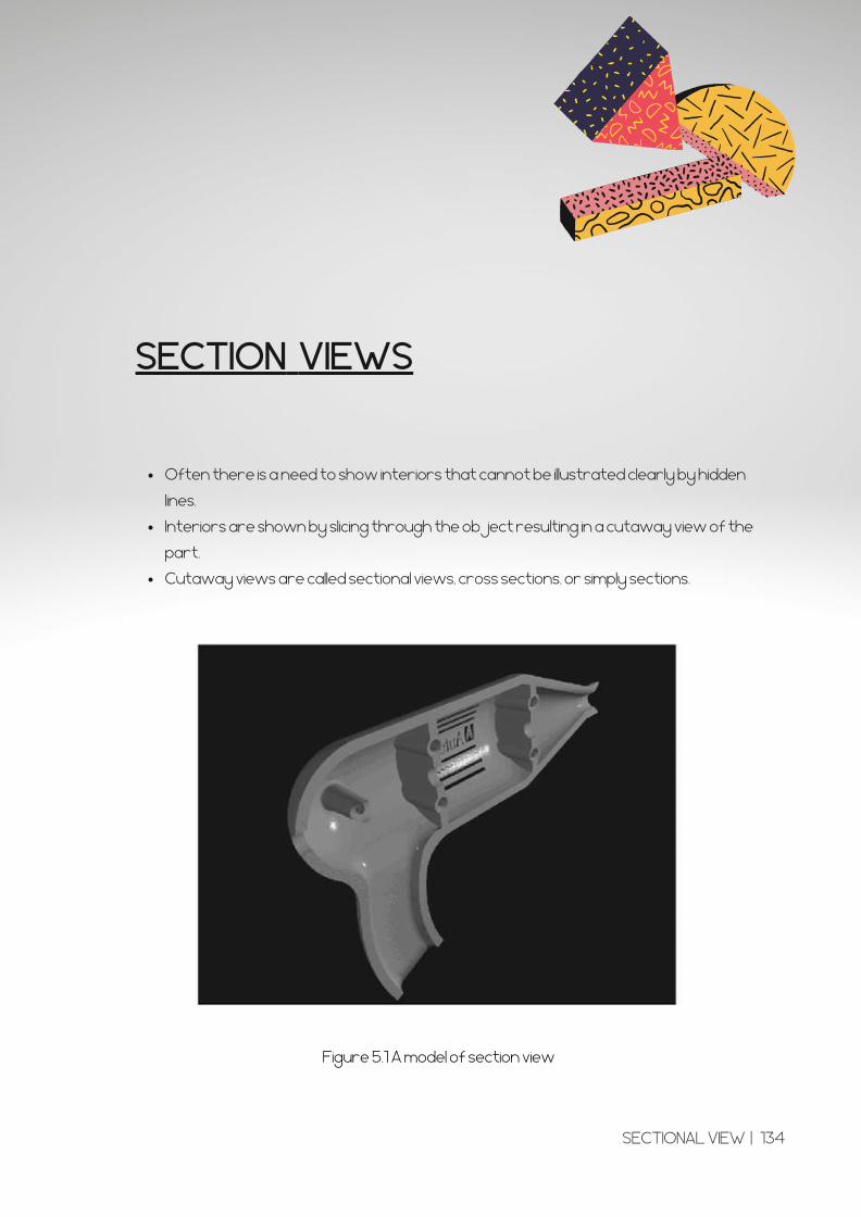
Often there is a need to show interiors that cannot be illustrated clearly by hidden
lines.
Interiors are shown by slicing through the object resulting in a cutaway view of the
part.
Cutaway views are called sectional views, cross sections, or simply sections.
SECTION VIEWS
Figure 5.1 A model of section view
SECTIONAL VIEW | 134
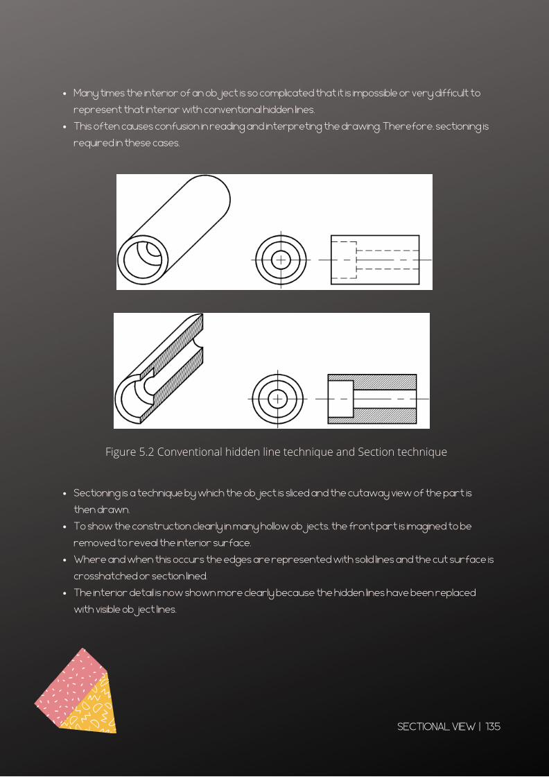
Many times the interior of an object is so complicated that it is impossible or very difficult to
represent that interior with conventional hidden lines.
This often causes confusion in reading and interpreting the drawing. Therefore, sectioning is
required in these cases.
Figure 5.2 Conventional hidden line technique and Section technique
Sectioning is a technique by which the object is sliced and the cutaway view of the part is
then drawn.
To show the construction clearly in many hollow objects, the front part is imagined to be
removed to reveal the interior surface.
Where and when this occurs the edges are represented with solid lines and the cut surface is
crosshatched or section lined.
The interior detail is now shown more clearly because the hidden lines have been replaced
with visible object lines.
SECTIONAL VIEW | 135
VISUALIZING A SECTION VIEW
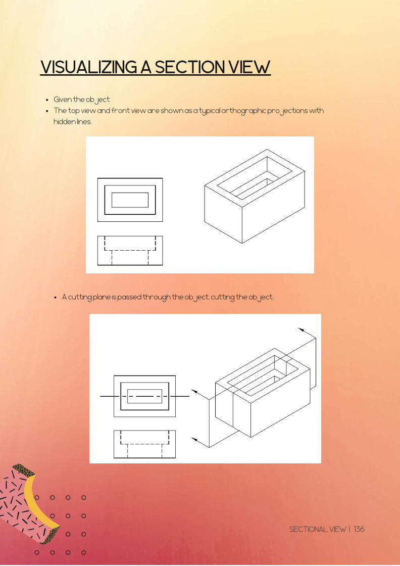
Given the object
The top view and front view are shown as a typical orthographic projections with
hidden lines.
A cutting plane is passed through the object, cutting the object.
SECTIONAL VIEW | 136
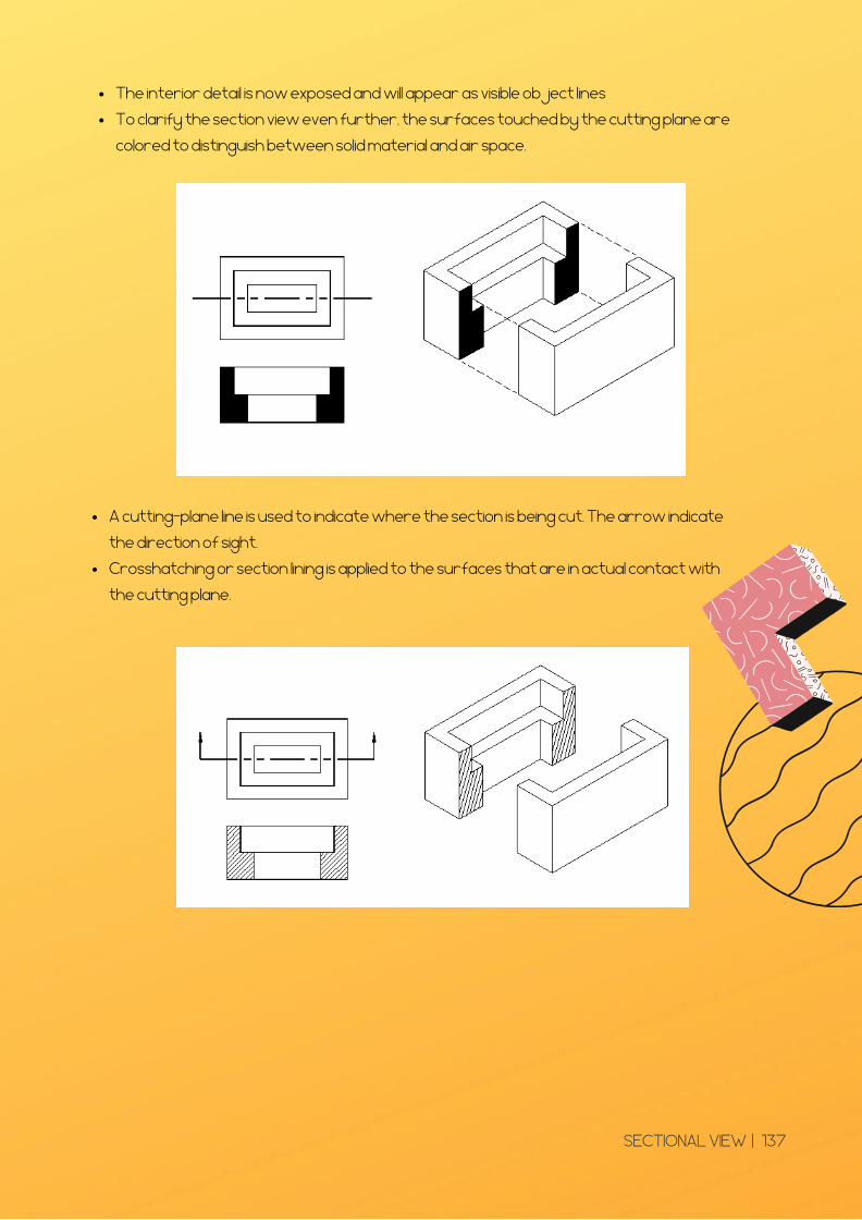
The interior detail is now exposed and will appear as visible object lines
To clarify the section view even further, the surfaces touched by the cutting plane are
colored to distinguish between solid material and air space.
A cutting-plane line is used to indicate where the section is being cut. The arrow indicate
the direction of sight.
Crosshatching or section lining is applied to the surfaces that are in actual contact with
the cutting plane.
SECTIONAL VIEW | 137
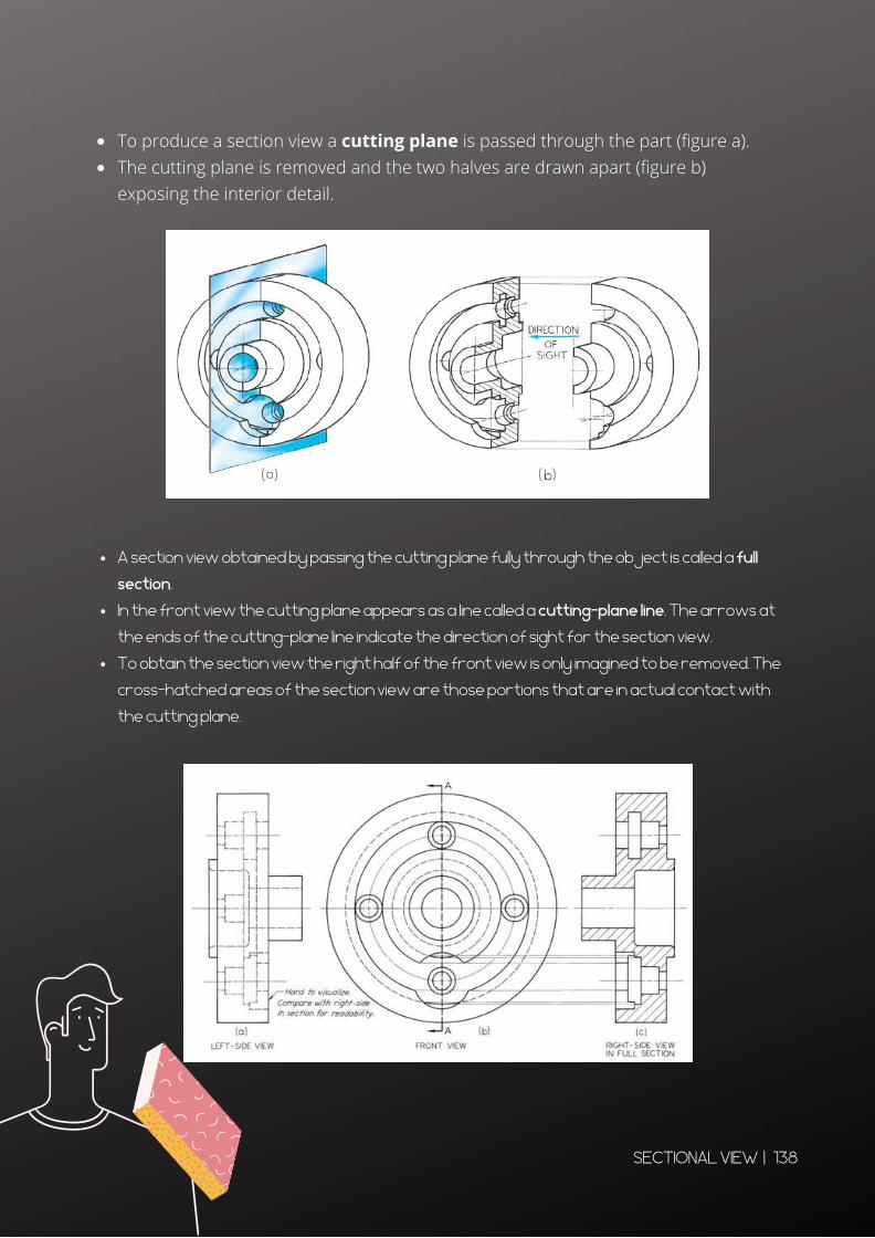
To produce a section view a cutting plane is passed through the part (figure a).The cutting plane is removed and the two halves are drawn apart (figure b)exposing the interior detail.
A section view obtained by passing the cutting plane fully through the object is called a full
section.
In the front view the cutting plane appears as a line called a cutting-plane line. The arrows at
the ends of the cutting-plane line indicate the direction of sight for the section view.
To obtain the section view the right half of the front view is only imagined to be removed. The
cross-hatched areas of the section view are those portions that are in actual contact with
the cutting plane.
SECTIONAL VIEW | 138
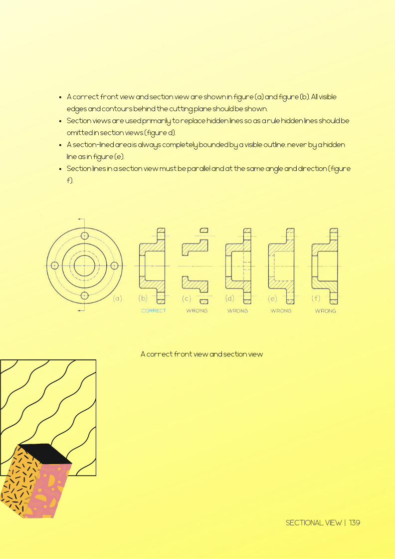
A correct front view and section view are shown in figure (a) and figure (b). All visible
edges and contours behind the cutting plane should be shown.
Section views are used primarily to replace hidden lines so as a rule hidden lines should be
omitted in section views (figure d).
A section-lined area is always completely bounded by a visible outline, never by a hidden
line as in figure (e).
Section lines in a section view must be parallel and at the same angle and direction (figure
f).
A correct front view and section view
SECTIONAL VIEW | 139
SECTIONING LINING
SYMBOLS
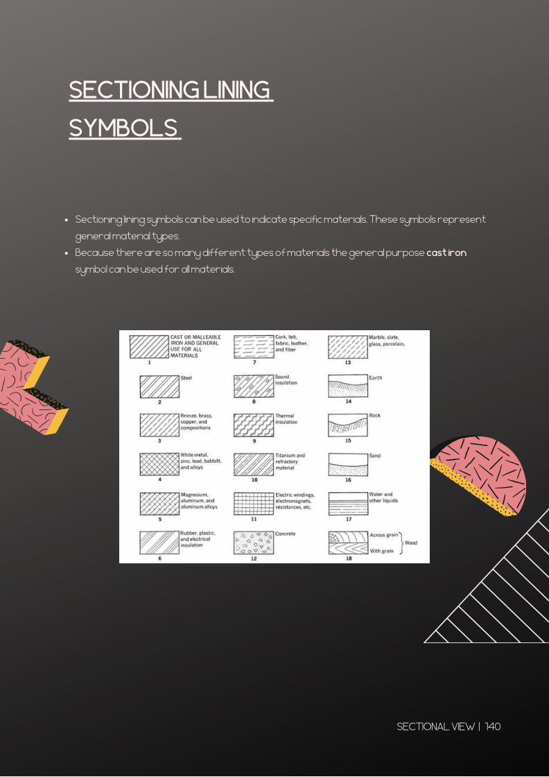
Sectioning lining symbols can be used to indicate specific materials. These symbols represent
general material types.
Because there are so many different types of materials the general purpose cast iron
symbol can be used for all materials.
SECTIONAL VIEW | 140
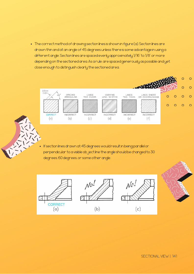
The correct method of drawing section lines is shown in figure (a). Section lines are
drawn thin and at an angle of 45 degrees unless there is some advantage in using a
different angle. Section lines are spaced evenly approximately 1/16” to 1/8” or more
depending on the sectioned area. As a rule, are spaced generously as possible and yet
close enough to distinguish clearly the sectioned area.
If section lines drawn at 45 degrees would result in being parallel or
perpendicular to a visible object line the angle should be changed to 30
degrees, 60 degrees, or some other angle.
SECTIONAL VIEW | 141
CUTTING-PLANE LINE
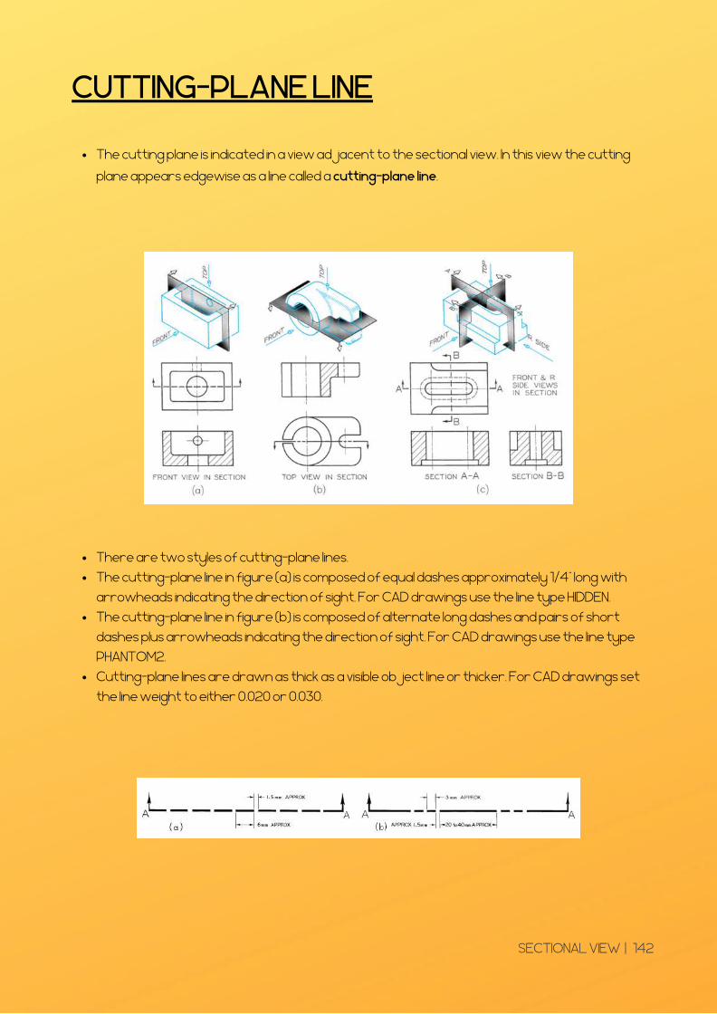
The cutting plane is indicated in a view adjacent to the sectional view. In this view the cutting
plane appears edgewise as a line called a cutting-plane line.
There are two styles of cutting-plane lines.
The cutting-plane line in figure (a) is composed of equal dashes approximately 1/4” long with
arrowheads indicating the direction of sight. For CAD drawings use the line type HIDDEN.
The cutting-plane line in figure (b) is composed of alternate long dashes and pairs of short
dashes plus arrowheads indicating the direction of sight. For CAD drawings use the line type
PHANTOM2.
Cutting-plane lines are drawn as thick as a visible object line or thicker. For CAD drawings set
the line weight to either 0.020 or 0.030.
SECTIONAL VIEW | 142
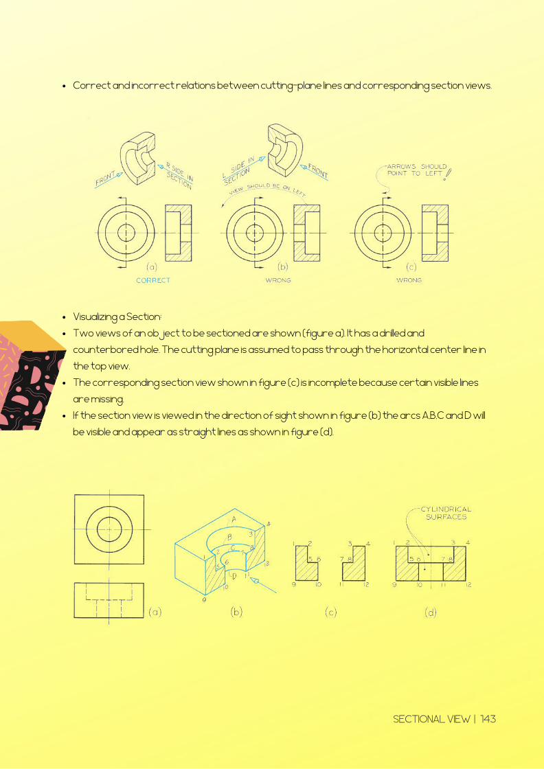
Visualizing a Section:
Two views of an object to be sectioned are shown (figure a). It has a drilled and
counterbored hole. The cutting plane is assumed to pass through the horizontal center line in
the top view.
The corresponding section view shown in figure (c) is incomplete because certain visible lines
are missing.
If the section view is viewed in the direction of sight shown in figure (b) the arcs A,B,C and D will
be visible and appear as straight lines as shown in figure (d).
Correct and incorrect relations between cutting-plane lines and corresponding section views.
SECTIONAL VIEW | 143
TYPES OF SECTIONING
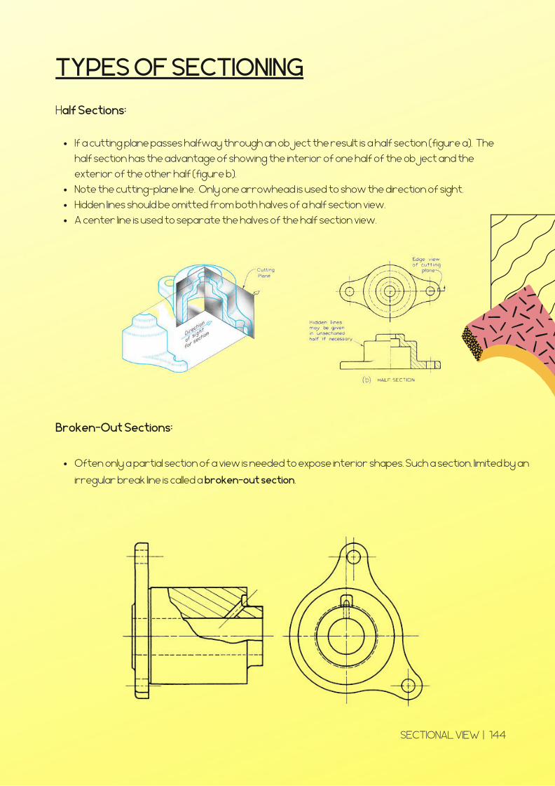
If a cutting plane passes halfway through an object the result is a half section (figure a). The
half section has the advantage of showing the interior of one half of the object and the
exterior of the other half (figure b).
Note the cutting-plane line. Only one arrowhead is used to show the direction of sight.
Hidden lines should be omitted from both halves of a half section view.
A center line is used to separate the halves of the half section view.
Half Sections:
Often only a partial section of a view is needed to expose interior shapes. Such a section, limited by an
irregular break line is called a broken-out section.
Broken-Out Sections:
SECTIONAL VIEW | 144
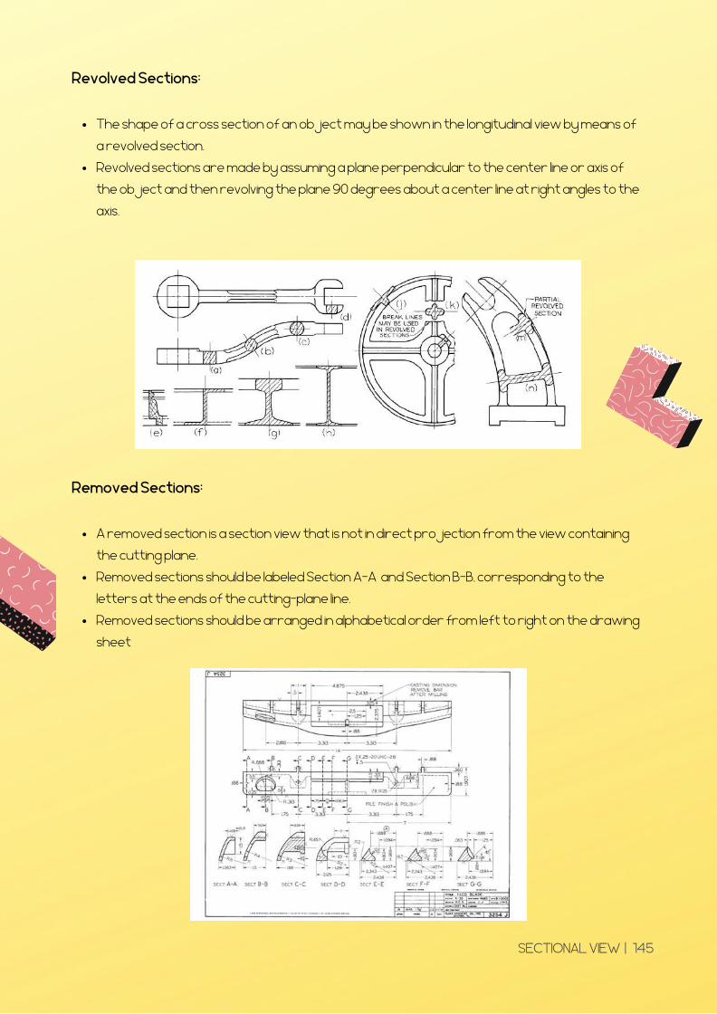
The shape of a cross section of an object may be shown in the longitudinal view by means of
a revolved section.
Revolved sections are made by assuming a plane perpendicular to the center line or axis of
the object and then revolving the plane 90 degrees about a center line at right angles to the
axis.
Revolved Sections:
A removed section is a section view that is not in direct projection from the view containing
the cutting plane.
Removed sections should be labeled Section A-A and Section B-B, corresponding to the
letters at the ends of the cutting-plane line.
Removed sections should be arranged in alphabetical order from left to right on the drawing
sheet
Removed Sections:
SECTIONAL VIEW | 145
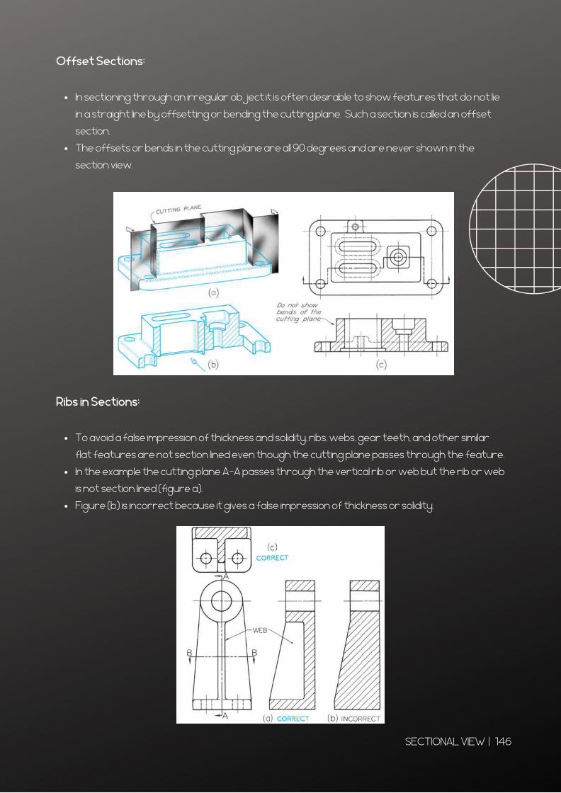
In sectioning through an irregular object it is often desirable to show features that do not lie
in a straight line by offsetting or bending the cutting plane. Such a section is called an offset
section.
The offsets or bends in the cutting plane are all 90 degrees and are never shown in the
section view.
Offset Sections:
To avoid a false impression of thickness and solidity, ribs, webs, gear teeth, and other similar
flat features are not section lined even though the cutting plane passes through the feature.
In the example the cutting plane A-A passes through the vertical rib or web but the rib or web
is not section lined (figure a).
Figure (b) is incorrect because it gives a false impression of thickness or solidity.
Ribs in Sections:
SECTIONAL VIEW | 146
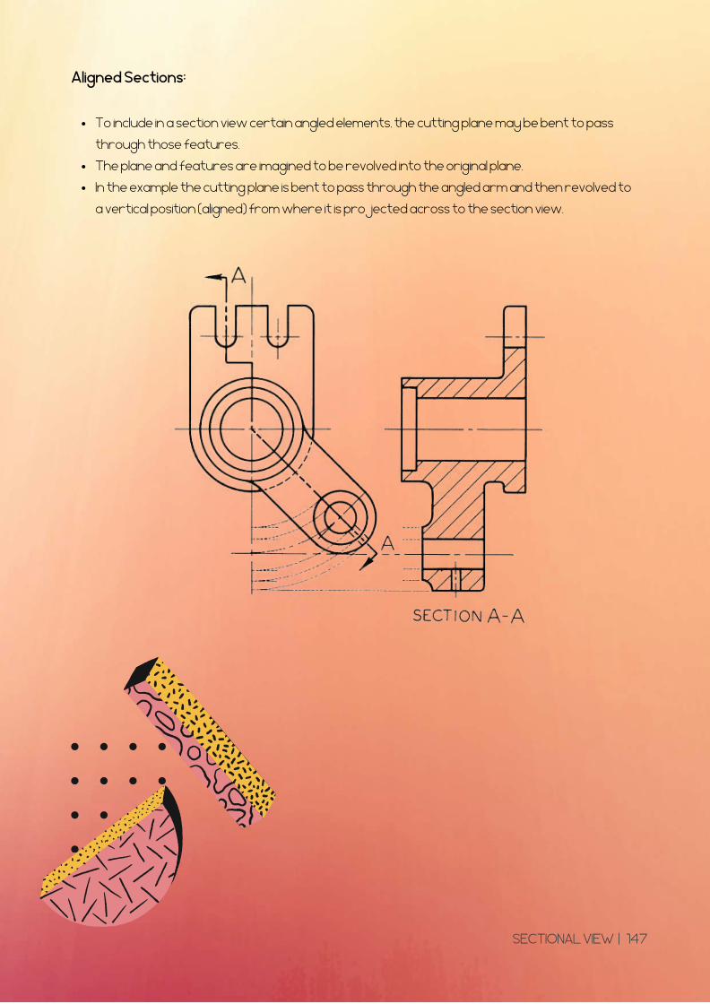
To include in a section view certain angled elements, the cutting plane may be bent to pass
through those features.
The plane and features are imagined to be revolved into the original plane.
In the example the cutting plane is bent to pass through the angled arm and then revolved to
a vertical position (aligned) from where it is projected across to the section view.
Aligned Sections:
SECTIONAL VIEW | 147
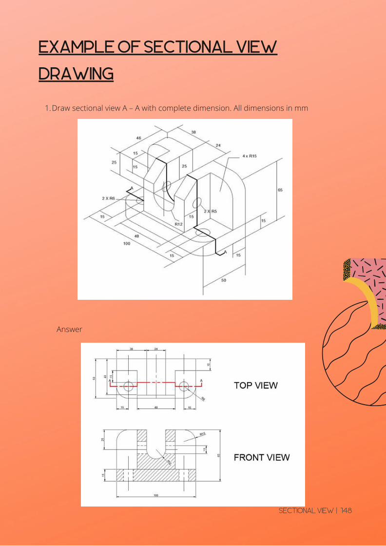
EXAMPLE OF SECTIONAL VIEW
DRAWING
Draw sectional view A – A with complete dimension. All dimensions in mm1.
Answer
SECTIONAL VIEW | 148
TUTORIAL
CHAPTER 5
SECTIONAL VIEW | 149
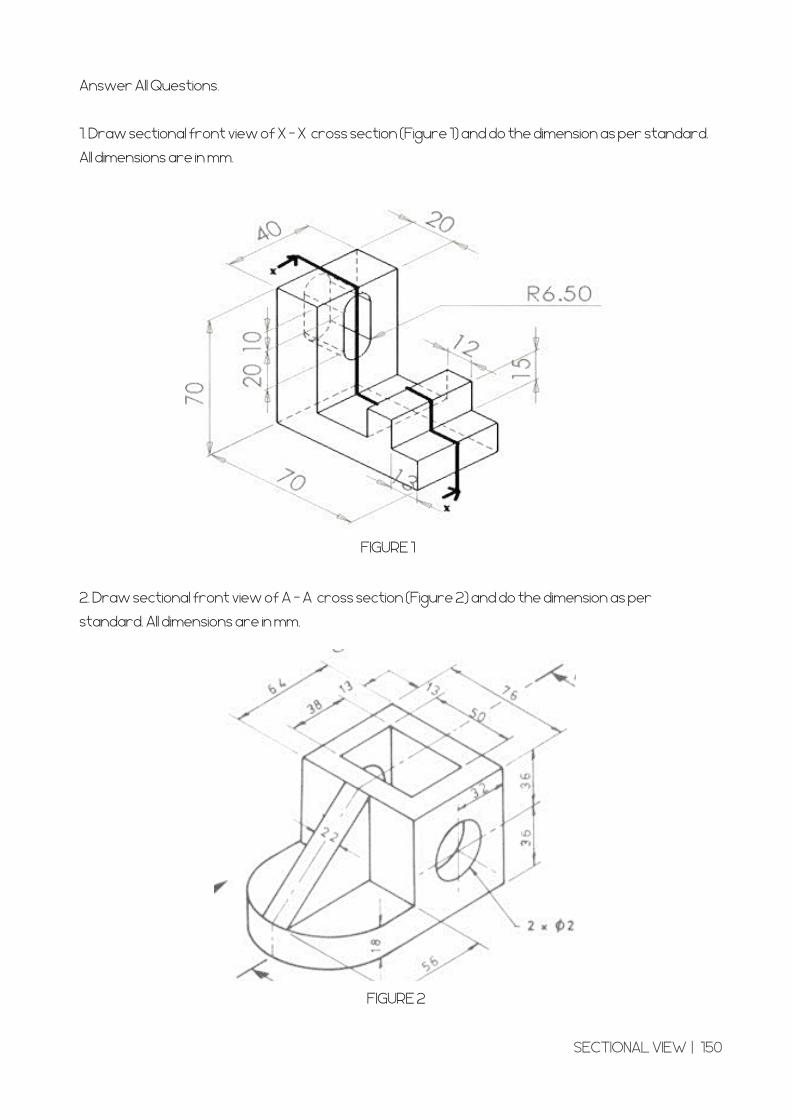
Answer All Questions.
1. Draw sectional front view of X – X cross section (Figure 1) and do the dimension as per standard.
All dimensions are in mm.
FIGURE 1
2. Draw sectional front view of A – A cross section (Figure 2) and do the dimension as per
standard. All dimensions are in mm.
FIGURE 2
SECTIONAL VIEW | 150
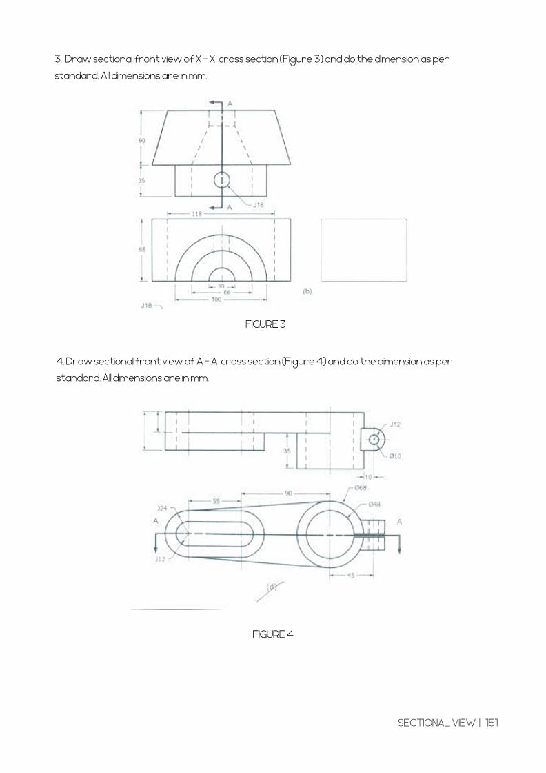
3. Draw sectional front view of X – X cross section (Figure 3) and do the dimension as per
standard. All dimensions are in mm.
FIGURE 3
4. Draw sectional front view of A – A cross section (Figure 4) and do the dimension as per
standard. All dimensions are in mm.
FIGURE 4
SECTIONAL VIEW | 151

Md. Nasir Abd Manan, 2014, Lukisan Geometri danKejuruteraan;IBS BUKU SDN BHD, Petaling Jaya
Mohd Noh bin Sarip dan Md. Nasir Abd Manan, 2007 EngineeringDrawing Form 4 KBSM ; Dewan Bahasa dan Pustaka, KL
https://docplayer.info/97799429-Asas-lukisan-kejuruteraan.html
1.
REFFERENCES
5.
3.
4.
2.
http://engineeringessentials.com/ege5/files/ege/dim/dim_page
0.htm
Notes : Technical Drawings & GD&T
https://www.cqeacademy.com/cqe-body-of-
knowledge/product-process-design/technical-drawings-gdt/
6. Notes pdf: Agus Arsad, Azizul Azri Mustaffa ,ENGINEERING DRAWING SKKK 1021, UTM open courseware.
Abd. Razak B. Hj. Mohd Daim M. Alif AlBakri bin Abdullah dan SH. Yaacub
bin SH Attar , J1001 LUKISAN KEJURUTERAAN MODUL POLITEKNIK
7.
https://www.slideshare.net/wilsonarlenenavarro/drawing-tools
Title : List Of Engineering Drawing Tools | Drawing Instrument
https://edengdrawing.blogspot.com/2013/02/instruments-and-
materials-of-drawing.html
8.
9.

Publisher
Related Documents