I188 Rev D / MFP9720078 6 May 2013 - Trilingual Distributed by CAI Safety Systems

Welcome message from author
This document is posted to help you gain knowledge. Please leave a comment to let me know what you think about it! Share it to your friends and learn new things together.
Transcript
I188 Rev D / MFP97200786 May 2013 - Trilingual
Distributed byCAI Safety Systems
2
Table of Contents
1.0 Purpose........................................................................................................................ 3 2.0 General Requirements, Warnings and Limitations...................................................... 3-4
2.1 General Fall Protection Warnings 2.2 System Warnings and Limitations
3.0 System Requirements.................................................................................................. 5 4.0 System Diagrams and Description of Components..................................................... 6-8 4.1 Vi-Go AUTOMATIC PASS-THROUGH System 4.2 Vi-Go MANUAL PASS-THROUGH System
4.3 System Replacement Parts 5.0 System Installation....................................................................................................... 8-14 5.1 Installation of Top Bracket Assembly 5.2 Installation of Cable to Top Bracket Assembly 5.3 Installation of Intermediate Cable Guides 5.4 Installation of Bottom Bracket Assembly 5.5 Installation of Cable and Tensioning Assembly to Bottom Bracket Assembly 5.6 Options for Terminating Cable in the Field 5.7 Optional Vi-Go Anchorage Connector 6.0 System Operation........................................................................................................ 14 7.0 Training........................................................................................................................ 14 8.0 Inspection and Maintenance........................................................................................ 15 Product Labels............................................................................................................. 44 Inspection and Maintenance Log................................................................................. 45 Notes............................................................................................................................ 46 Warranty....................................................................................................................... 47
Directives d'utilisation – Français........................................16-29
Instrucciones Para El Usuario - Español..........................................30-43
Distributed byCAI Safety Systems
DISTRIBUTED BY CAI SAFETY SYSTEMS | Phone: (888) 246 6999 | Web: caisafety.com | Email: [email protected]

3
User Instruct ions - Engl ish
Questions? CALL1.800.873.5242
It is crucial that the authorized person/user of this equipment read and understand these instructions. In addition, federal law requires employers to ensure that all users are trained in the proper installation, use, inspection, and maintenance of fall protection equipment. Fall protection training should be an integral part of a comprehensive safety program.
Proper use of fall arrest systems can save lives and reduce the potential of serious injuries from a fall. The user must be aware that forces experienced during the arrest of a fall or prolonged suspension may cause bodily injury. Consult a physician if there is any question about the user’s ability to use this product. Pregnant women and minor children must not use this product.
2.0 General Requirements, Warnings and Limitations
Thank you for your purchase of Miller fall protection equipment manufactured by Honeywell Safety Products.
Miller equipment will provide you with years of use when cared for properly.
Thank You
2.1 General Fall Protection Warnings
All warnings and instructions shall be provided to authorized persons/users. Warnings and instructions must be read and understood prior to using this equipment.
All authorized persons/users must reference the regulations governing occupational safety, as well as applicable standards (i.e, ANSI or CSA). Refer to
regulations, and ANSI and CSA standards met by this system.
Proper precautions should always be taken to remove any obstructions, debris, material, or other recognized hazards from the work area that could cause injuries or interfere with the operation of the system.
All equipment must be inspected before each use according to the manufacturer’s instructions.
All persons using this equipment must read, understand and follow all instructions. Failure to do so may result in serious injury or death. Do not use this equipment un-less you are properly trained.
WARNING
on a regular basis.
To minimize the potential for accidental disengagement, a competent person must ensure system compatibility.
Equipment must not be altered in any way. Repairs must be performed only by the equipment manufacturer, or persons or entities authorized, in writing, by the manufacturer.
Any product exhibiting deformities, unusual wear, or deterioration must be immediately discarded.
Do not use if the unit or any part of the system appears to be damaged.
Any equipment subject to a fall must be removed from service.
Vi-Go Vertical Cable Lifeline Systems are innovative climbing and fall arrest systems that provide superior fall
1.0 Purpose
DISTRIBUTED BY CAI SAFETY SYSTEMS | Phone: (888) 246 6999 | Web: caisafety.com | Email: [email protected]

User Instruct ions - Engl ish
4
System CompatibilityVi-Go Vertical Cable Lifeline Systems are designed for use with Honeywell-approved components. Substitution or replacement with non-approved component combinations, sub-systems, or both, may affect or interfere with the safe function of each other and endanger the compatibility within the system. This incompatibility may affect the reliability and safety of the total system.
Vi-Go Systems must be used in conjunction with a Vi-Go Cable Sleeve with auto-locking carabiner (or other Honeywell-approved connector) and a Miller full-body harness equipped with a front attachment point designated for ladder climbing.
[NOTE: All instructions and warnings provided with the cable sleeve, connector and harness must be read and understood before using the equipment.]
System CapacityA maximum of four users may simultaneously be connected to a Vi-Go Vertical Cable Lifeline System so long as the load-bearing capacity of the base structure is adequate. For Vi-Go Systems using the 10 ft. (3m) top bracket assembly, the number of users is limited to two.
The distance between users must not be less than 5-1/4 ft. (1.6m) to ensure that, in the event of a fall, the person falling will not strike a user below. (Note: According to ANSI A14.3, only one worker may be on the system between cable guides.)
Fall ClearanceEnsure that adequate clearance exists in the fall path to avoid striking a lower level, some other object, or another user.
2.2 System Warnings and Limitations
Environmental HazardsUse of this equipment in areas where environmental hazards exist may require additional precautions to limit the possibility of injury to the user or damage to the equipment. Hazards may include, but are not limited to, extreme temperatures, caustic chemicals, corrosive environments, high voltage power lines, explosive or toxic gases, moving machinery, and sharp edges. Do not expose the equipment to any hazard which it is not designed to withstand. Consult the manufacturer in cases of doubt.
is positioned on an unstable surface, fine-grain material, or particulate.
The user shall have a rescue plan and the means at hand to implement it when using this equipment.
Never use fall protection equipment for purposes other than those for which it was designed. Fall protection equipment should never be used for towing or hoisting.
Never remove product labels, which include important warnings and information for the authorized person/user.
DISTRIBUTED BY CAI SAFETY SYSTEMS | Phone: (888) 246 6999 | Web: caisafety.com | Email: [email protected]

5
User Instruct ions - Engl ish
3.0 System Requirements
to be capable of withstanding the potential loads that may be applied in the event of a fall arrest and must meet
Ladder Requirements
to ANSI A14.3, the minimum width of the ladder should be 18 inches from inside rail to inside rail.
A system may be attached to square, diamond or L-shaped (angle iron) rungs so long as the rungs meet the mini-mum 3/4 inch and maximum 1-1/8 inches outer diameter requirements. A spacer may be required for angle iron installations. Please contact Honeywell Technical Service at 800-873-5242 for additional information and installa-tion assistance.
Top Bracket
Connection loads include system pretension and forces generated by arresting a fall. The load requirements vary due to number of users on the system and installation to the structure (i.e., number of rung clamp assemblies used).
For calculation purposes in determining the load each ladder rung must be able to withstand, assume the maxi-mum load on each bracket is distributed evenly throughout the number of top bracket rung clamp assemblies. [Example: Based on a single-user system with the top bracket installed with three rung connections, the assumed load for each rung would be 1,100 lbs. (3,300/3).] An additional top bracket rung clamp assembly can be pur-chased separately and used to spread the load requirements over four (4) rungs rather than three (3). [Example: For a system with two (2) users the loads transmitted to each rung is reduced from 1,267 lbs. (3,800/3) to 950 lbs. (3,800/4).]
Number of Simultaneous Users Maximum Load (lbs.)*For Vi-Go AUTOMATIC and MANUAL Systems:
1 3,300 lbs.2 3,800 lbs.3 4,300 lbs.4 4,800 lbs.
*The maximum load calculations provide a 2:1 safety factor.
Bottom Bracket
The bottom bracket connection must be capable of supporting a system load of 750 lbs. in the direction of loading.
DISTRIBUTED BY CAI SAFETY SYSTEMS | Phone: (888) 246 6999 | Web: caisafety.com | Email: [email protected]

User Instruct ions - Engl ish
6
4.1 Vi-Go AUTOMATIC PASS-THROUGH System
4.0 System Diagrams and Description of Components
4) Automatic Pass-Through Cable Guide
excessively in windy conditions and from coming in contact with the ladder or structure.
Automatic Pass-Through Cable Sleeve to bypass guide without manual assistance, offering the user greater comfort through hands-free trailing, quicker climbing and descending, and the highest level of safety.
5) Vi-Go Automatic Pass-Through Cable Sleeve
Cable sleeve purchased separately. Available with integral swivel and auto-locking carabiner, with the carabiner only, or without a connector.
operation.
of the cable sleeve to the cable.
to initial position.
of the cable sleeve from the cable.
Built-in shock absorber/fall indicator further reduces fall arrest forces and provides for ease of inspection.
3) Cable Lifeline
1
3
4
5
6
21) Top Bracket Assembly with Inline Shock Absorber
the system and structure in the event of a fall.May be installed to extend above the ladder to allow workers to step safely onto the platform without disconnecting from the lifeline for maximum protection.
6) Bottom Bracket Assembly with Lifeline Tensioner
properly adjusted and prevents ladder rung deformation.
2) Quick Link
the inline shock absorber.
DISTRIBUTED BY CAI SAFETY SYSTEMS | Phone: (888) 246 6999 | Web: caisafety.com | Email: [email protected]
7
User Instruct ions - Engl ish
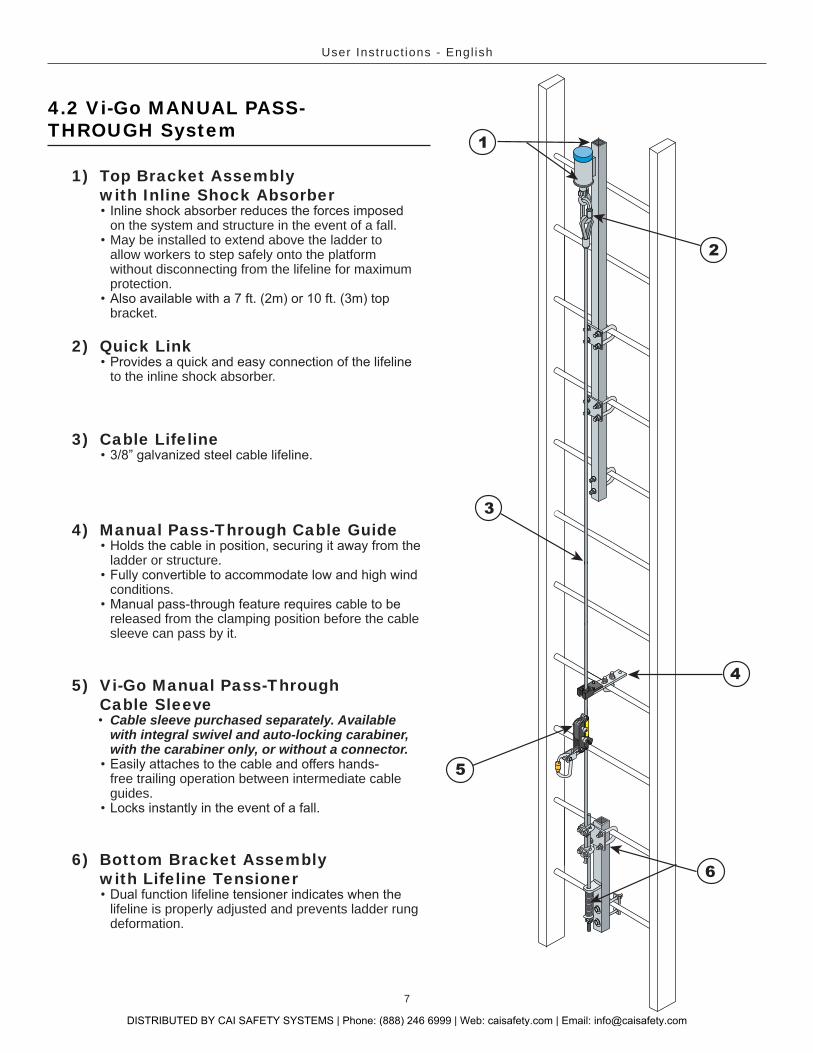
4.2 Vi-Go MANUAL PASS-THROUGH System
1) Top Bracket Assembly with Inline Shock Absorber
on the system and structure in the event of a fall.May be installed to extend above the ladder to allow workers to step safely onto the platform without disconnecting from the lifeline for maximum protection.
bracket.
6) Bottom Bracket Assembly with Lifeline Tensioner
lifeline is properly adjusted and prevents ladder rung deformation.
4) Manual Pass-Through Cable Guide
ladder or structure.
conditions.
released from the clamping position before the cable sleeve can pass by it.
5) Vi-Go Manual Pass-Through Cable Sleeve
Cable sleeve purchased separately. Available with integral swivel and auto-locking carabiner, with the carabiner only, or without a connector.
free trailing operation between intermediate cable guides.
3) Cable Lifeline
3
4
5
6
1
2
2) Quick Link
to the inline shock absorber.
DISTRIBUTED BY CAI SAFETY SYSTEMS | Phone: (888) 246 6999 | Web: caisafety.com | Email: [email protected]

User Instruct ions - Engl ish
8
4.3 System Replacement Parts
PartNo. Component Description
TRTB Top Bracket Assembly 5 ft. (1.5m) galvanized steel bracket (1-1/2” x 1-1/2” tube) includes inline shock absorber with shackle, two rung clamp assemblies (each w/4-hole mounting plate for 1-1/2" tube, two 3/8"-16 x 1-5/8" x 3-1/2" U-bolts, four 3/8" lockwashers, and four 3/8"-16 hex nut fasteners), and bottom rung clamp assembly (w/3/8"-16 x 1-5/8" x 3-1/2" U-bolt, two 3/8" lockwashers, two 3/8"-16 hex nut fasteners and two fastener caps).
TRTB-7 7 ft. (2m) Top BracketAssembly
7 ft. (2m) galvanized steel bracket (2” x 2” tube) includes inline shock absorber with shackle, two rung clamp assemblies (each w/4-hole mounting plate for 2" tube, two 3/8"-16 x 1-5/8" x 3-1/2" U-bolts, four 3/8" lockwashers, and four 3/8"-16 hex
two 3/8" lockwashers, and two 3/8"-16 hex nut fasteners). TRTB-10 10 ft. (3m) Top Bracket
Assembly10 ft. (3m) galvanized steel bracket (2” x 2” tube) includes inline shock absorber with shackle, two rung clamp assemblies (each w/4-hole mounting plate for 2" tube, two 3/8"-16 x 1-5/8" x 3-1/2" U-bolts, four 3/8" lockwashers, and four 3/8"-16 hex
two 3/8" lockwashers, and two 3/8"-16 hex nut fasteners). TRRCA Extra Rung Clamp Assembly
(for 5 ft. top bracket)Includes 4-hole mounting plate for 1-1/2" tube, two 3/8"-16 x 1-5/8" x 3-1/2" U-bolts, four 3/8" lockwashers, and four 3/8"-16 hex nut fasteners
TRRCA-10 Extra Rung Clamp Assembly(for 7ft. & 10 ft. top brackets)
Includes 4-hole mounting plate for 2" tube, two 3/8"-16 x 1-5/8" x 3-1/2" U-bolts, four 3/8" lockwashers, and four 3/8"-16 hex nut fasteners
TRLL Cable Lifeline 3/8” diameter galvanized steel cable with thimble. Various lengths available.TRQL Quick Link Galvanized steel quick-link used for connecting cable to shackle on inline shock absorber.VGCG Automatic Pass-Through
Cable Guide 1.5mm locknuts.TRCG Manual Pass-Through
Cable GuideGalvanized steel cable bracket with convertible polyurethane cable retainer head includes 3/8"-16 x 1-1/4" x 2" U-Bolt, two
TRBB Bottom Bracket Assembly Galvanized steel bracket (1-1/2” x 1-1/2” tube) includes rung clamp assembly (w/4-hole mounting plate for 1-1/2" tube, two 3/8"-16 x 1-5/8" x 3-1/2" U-bolts, four 3/8" lockwashers, and four 3/8"-16 hex nut fasteners), bottom rung clamp assembly
fasteners), and tensioning rod assembly (w/compression spring, two saddle clips, 7/16" washer, and six 7/16"-14 hex nut fasteners).
Model No. Cable Sleeve
VGCS Vi-Go Automatic Pass-Through Cable Sleeve [Also available with carabiner (VGCS-C) or with integral swivel and carabiner (VGCS-SC)] TRCS Vi-Go Manual Pass-Through Cable Sleeve [Also available with carabiner (TRCS-C) or with integral swivel and carabiner (TRCS-SC)]
5.0 System Installation
(see 8.0 Inspection and Maintenance). Do not use if there are any damaged or missing parts (see 4.3 System Replacement Parts).
resulting from a fall (see 3.0 System Requirements). may be purchased
separately. Contact your Miller distributor.
WARNING: Personal fall protection is required during installation. Persons installing the system must use caution and shall not be exposed to a fall hazard during the installation procedure. Do not connect to any component of a partially installed system.
System Installation Overview: The recommended installation procedure of the Vi-Go Vertical Cable Lifeline System is to install from the top of the ladder down.Tools Required for Installation: Torque wrench, standard sockets--7/8" and 3/4", deep socket--9/16", standard wrenches--7/16", 11/16" and 3/4", crowfoot wrench--17mm (for part VGCG only), cable cutters--minimum 3/8" capacity needed (5/8" capacity preferred), and a tape measure.
TRIK
DISTRIBUTED BY CAI SAFETY SYSTEMS | Phone: (888) 246 6999 | Web: caisafety.com | Email: [email protected]
9
User Instruct ions - Engl ish
5.1 Installation of Top Bracket Assembly
MountingPlate
Washer
FastenerCap
Fastener
U-Bolt
Fig. 1a
Fig. 1d
Fastener
Washers
MountingPlate
Bolt
Fig. 1b
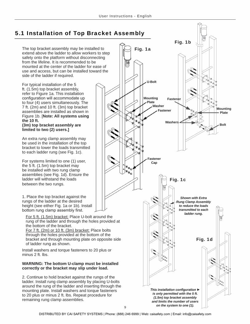
Shown with Extra Rung Clamp Assembly
to reduce the loads transmitted to each
ladder rung.
Fig. 1c
is only permitted with the 5 ft. (1.5m) top bracket assembly
and limits the number of userson the system to one (1).
The top bracket assembly may be installed to extend above the ladder to allow workers to step safety onto the platform without disconnecting from the lifeline. It is recommended to be mounted at the center of the ladder for ease of use and access, but can be installed toward the side of the ladder if required.
For typical installation of the 5 ft. (1.5m) top bracket assembly, refer to Figure 1a. This installation
to four (4) users simultaneously. The 7 ft. (2m) and 10 ft. (3m) top bracket assemblies are installed as shown in Figure 1b. [Note: All systems using the 10 ft.(3m) top bracket assembly are limited to two (2) users.]
An extra rung clamp assembly may be used in the installation of the top bracket to lower the loads transmitted to each ladder rung (see Fig. 1c).
For systems limited to one (1) user, the 5 ft. (1.5m) top bracket may be installed with two rung clamp assemblies (see Fig. 1d). Ensure the ladder will withstand the loads between the two rungs.
1. Place the top bracket against the rungs of the ladder at the desired height (see either Fig. 1a or 1b). Install
For 5 ft. (1.5m) bracket: Place U-bolt around the rung of the ladder and through the holes provided at the bottom of the bracket. For 7 ft. (2m) or 10 ft. (3m) bracket: Place bolts through the holes provided at the bottom of the bracket and through mounting plate on opposite side of ladder rung as shown.
Install washers and torque fasteners to 20 plus or minus 2 ft. lbs.
WARNING: The bottom U-clamp must be installed correctly or the bracket may slip under load.
2. Continue to hold bracket against the rungs of the ladder. Install rung clamp assembly by placing U-bolts around the rung of the ladder and inserting through the mounting plate. Install washers and torque fasteners to 20 plus or minus 2 ft. lbs. Repeat procedure for remaining rung clamp assemblies.
DISTRIBUTED BY CAI SAFETY SYSTEMS | Phone: (888) 246 6999 | Web: caisafety.com | Email: [email protected]

User Instruct ions - Engl ish
10
5.2 Installation of Cable to Top Bracket Assembly
Use only Honeywell-approved cable. Inspect cable before installation. Do not install damaged cable. Safety glasses and gloves should be worn when handling cable.
When cutting the cable on site during the installation procedure is preferred or necessary, refer to 5.6 Options for Terminating Cable in the Field. WARNING: All instructions and warnings provided with the cable
1. Install quick link to cable thimble (see Fig. 2).2. Then connect quick link with cable to the shackle
on the underside of the inline shock absorber. Tighten quick link until snug. Do not use if quick link does not close and tighten.
shackle bolt and bent over so that it will not back
MISSING.
5.3 Installation of Intermediate Cable Guides
Intermediate Cable Guides are designed to keep the climber from
placed at 25 ft. (7.6m) minimum to 40 ft. (12.2m) maximum intervals along the cable from the top bracket to the bottom bracket. Cable guides may be placed at any point along the cable that may come in contact with the ladder or structure. For installations in situations of vibration or high wind, consideration should be given to placing the intermediates closer together.
AUTOMATIC Pass-Through Cable Guides
1. Place intermediate cable guide against ladder rung (see Fig. 3). 2. Install U-bolt around ladder rung and through holes provided in
guide as shown.3. Install washers and torque fasteners to 20 plus or minus 2 ft. lbs.
Fig. 3
Inline Shock
Absorber
Shackle
QuickLink
CotterPin
Fig. 2
DISTRIBUTED BY CAI SAFETY SYSTEMS | Phone: (888) 246 6999 | Web: caisafety.com | Email: [email protected]
11
User Instruct ions - Engl ish
Washer
Fastener
U-Bolt
MountingPlate
Mounting Bolt
Typical Installation 90 Degree Installation
Fig. 4a
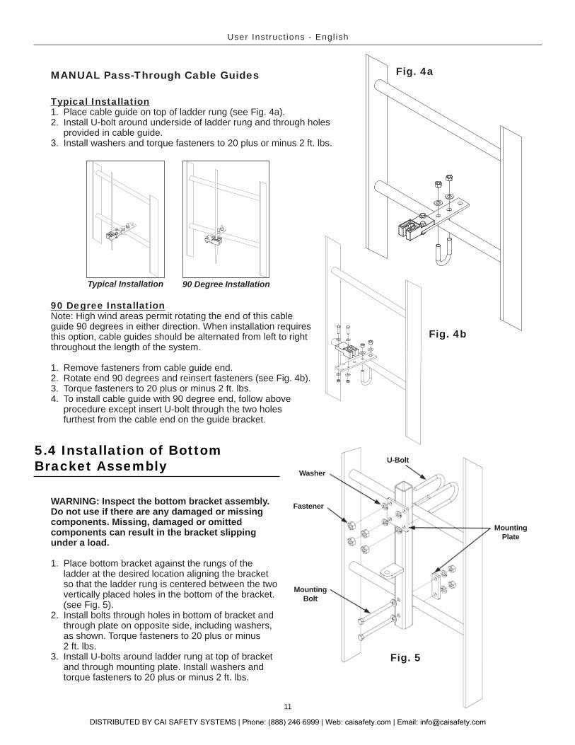
90 Degree InstallationNote: High wind areas permit rotating the end of this cable guide 90 degrees in either direction. When installation requires this option, cable guides should be alternated from left to right throughout the length of the system.
1. Remove fasteners from cable guide end.2. Rotate end 90 degrees and reinsert fasteners (see Fig. 4b).3. Torque fasteners to 20 plus or minus 2 ft. lbs.4. To install cable guide with 90 degree end, follow above
procedure except insert U-bolt through the two holes furthest from the cable end on the guide bracket.
Fig. 4b
MANUAL Pass-Through Cable Guides
Typical Installation1. Place cable guide on top of ladder rung (see Fig. 4a).2. Install U-bolt around underside of ladder rung and through holes
provided in cable guide. 3. Install washers and torque fasteners to 20 plus or minus 2 ft. lbs.
5.4 Installation of BottomBracket Assembly
WARNING: Inspect the bottom bracket assembly. Do not use if there are any damaged or missing components. Missing, damaged or omitted components can result in the bracket slipping under a load.
1. Place bottom bracket against the rungs of the ladder at the desired location aligning the bracket so that the ladder rung is centered between the two vertically placed holes in the bottom of the bracket. (see Fig. 5).
2. Install bolts through holes in bottom of bracket and through plate on opposite side, including washers, as shown. Torque fasteners to 20 plus or minus 2 ft. lbs.
3. Install U-bolts around ladder rung at top of bracket and through mounting plate. Install washers and torque fasteners to 20 plus or minus 2 ft. lbs.
Fig. 5
DISTRIBUTED BY CAI SAFETY SYSTEMS | Phone: (888) 246 6999 | Web: caisafety.com | Email: [email protected]

User Instruct ions - Engl ish
12
5.5 Installation of Cableand Tensioning Assemblyto Bottom Bracket Assembly
1. Install saddle clips loosely around cable attached to tension rod (see Fig. 6).
2. Slide the tension rod down the cable and through
amount of threads are through to install the compression spring, washer and tensioning nut.
3. Remove excess cable by pulling cable through the saddle clips. Tighten and torque saddle clips to 40 to 45 ft. lbs.
4. Tighten tensioning nut until cable is taut.
achieved. Do not completely compress spring.
repeat procedure from Step 3.5. When proper tensioning of cable is achieved,
install jam nut against tensioning nut.6. Discard excess cable by cutting below the lower
Fig. 6
Saddle Clip
Compression Spring
Tension Rod
Washer
Jam Nut
TensioningNut
required. Using a hand punch, designate the appropriate system capacity rating, installation date and service/inspection dates using the spaces provided on the label. Attach the label to the ladder or structure with the nylon tie provided. Attach the label to the system where it is easily accessible to anyone using the system. Record
Assembly with Tensioning Assembly and
Cable Installed
5-1/2"
DISTRIBUTED BY CAI SAFETY SYSTEMS | Phone: (888) 246 6999 | Web: caisafety.com | Email: [email protected]
13
User Instruct ions - Engl ish
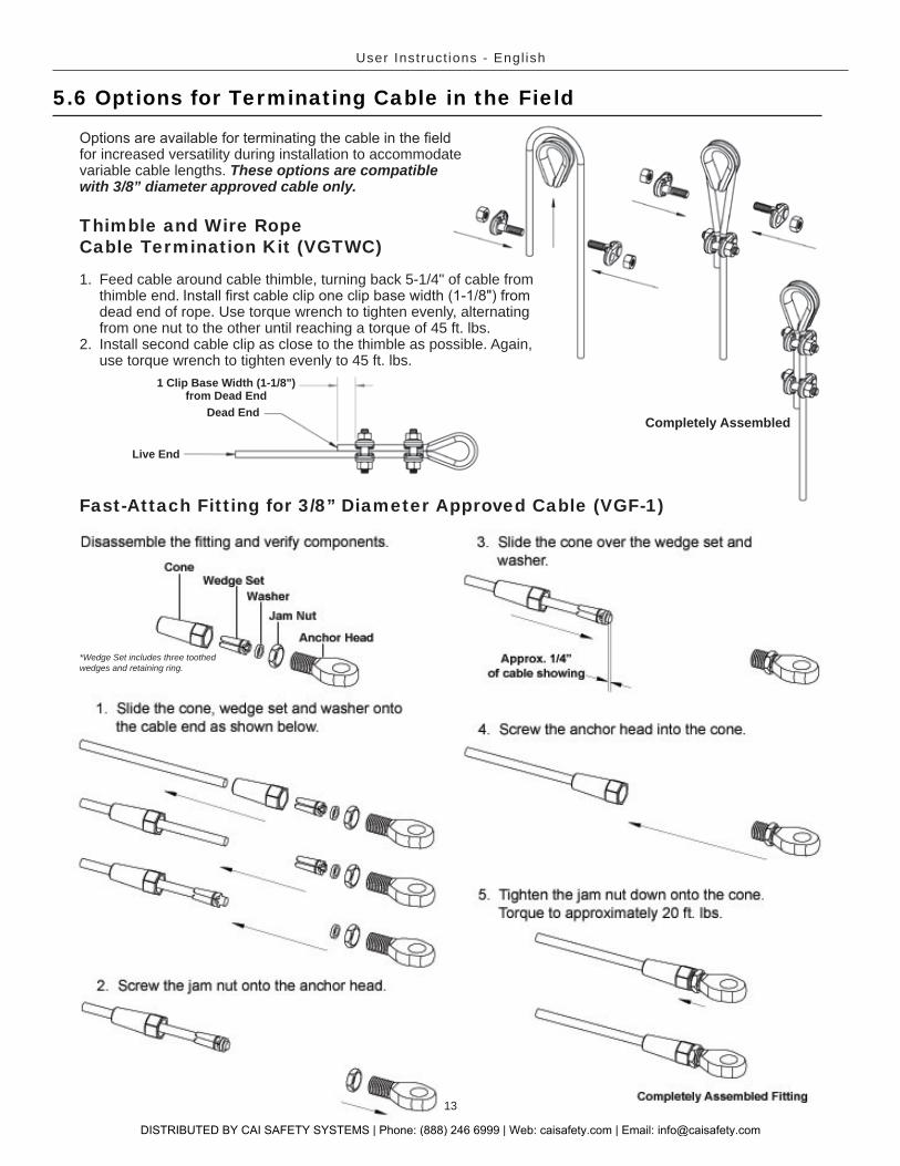
5.6 Options for Terminating Cable in the Field
Thimble and Wire RopeCable Termination Kit (VGTWC)
Fast-Attach Fitting for 3/8” Diameter Approved Cable (VGF-1)
Dead End
1 Clip Base Width (1-1/8")from Dead End
Live End
for increased versatility during installation to accommodate variable cable lengths. These options are compatible with 3/8” diameter approved cable only.
1. Feed cable around cable thimble, turning back 5-1/4" of cable from thimble end. dead end of rope. Use torque wrench to tighten evenly, alternating from one nut to the other until reaching a torque of 45 ft. lbs.
2. Install second cable clip as close to the thimble as possible. Again, use torque wrench to tighten evenly to 45 ft. lbs.
Completely Assembled
*Wedge Set includes three toothed wedges and retaining ring.
DISTRIBUTED BY CAI SAFETY SYSTEMS | Phone: (888) 246 6999 | Web: caisafety.com | Email: [email protected]

User Instruct ions - Engl ish
14
7.0 TrainingIt is the responsibility of the user and the purchaser of this equipment to assure they are familiar with these instructions and are trained in the proper use, installation, operation, inspection, maintenance and limitations of this product. Training should be conducted periodically and without exposing the trainee to a fall hazard.
Training is an integral part of our Total Solution in fall protection, since no fall protection equipment – regardless of how effective – can save an employee who is not trained in its use. To meet this crucial requirement, Miller Training provides the knowledge and skills necessary to achieve a safe, more productive work environment. For more information on Miller Training, contact a representative today: 800.873.5242.
6.0 System Operation1. Don a Miller full-body harness according to the manufacturer’s instructions. 2. Install the Vi-Go Cable Sleeve to the vertical cable lifeline according to the manufacturer’s instructions.3. Attach the cable sleeve to the front attachment point, designated for ladder climbing, of the full-body harness
using a Miller approved auto-locking carabiner or other Miller approved connector.4. Verify that the carabiner (or connector) keeper/gate is closed and locked.5. Ascend and descend the ladder passing intermediate cable guides per the manufacturer’s instructions
supplied with the cable sleeve.
5.7 Optional Vi-Go Anchorage Connector
The Vi-Go Anchorage Connector is designed to provide a convenient tie-off point for workers when entering/exiting at the top of Vi-Go Vertical Cable Lifeline Systems. The Vi-Go Anchorage Connector is designed for one person only with a capacity of 310 lbs. (140.6kg).
Model Compatible Top Bracket AssemblyTRS-AC1 Compatible with the 5ft. (1.5m) top bracket
TRS-AC2 Compatible with the 7 ft. (2m) and 10 ft. (3m) top
Vi-Go Anchorage Connector
WARNING: All instructions and warnings provided with the anchorage connector must be read and understood before using the equipment.
TRS-AC2
DISTRIBUTED BY CAI SAFETY SYSTEMS | Phone: (888) 246 6999 | Web: caisafety.com | Email: [email protected]
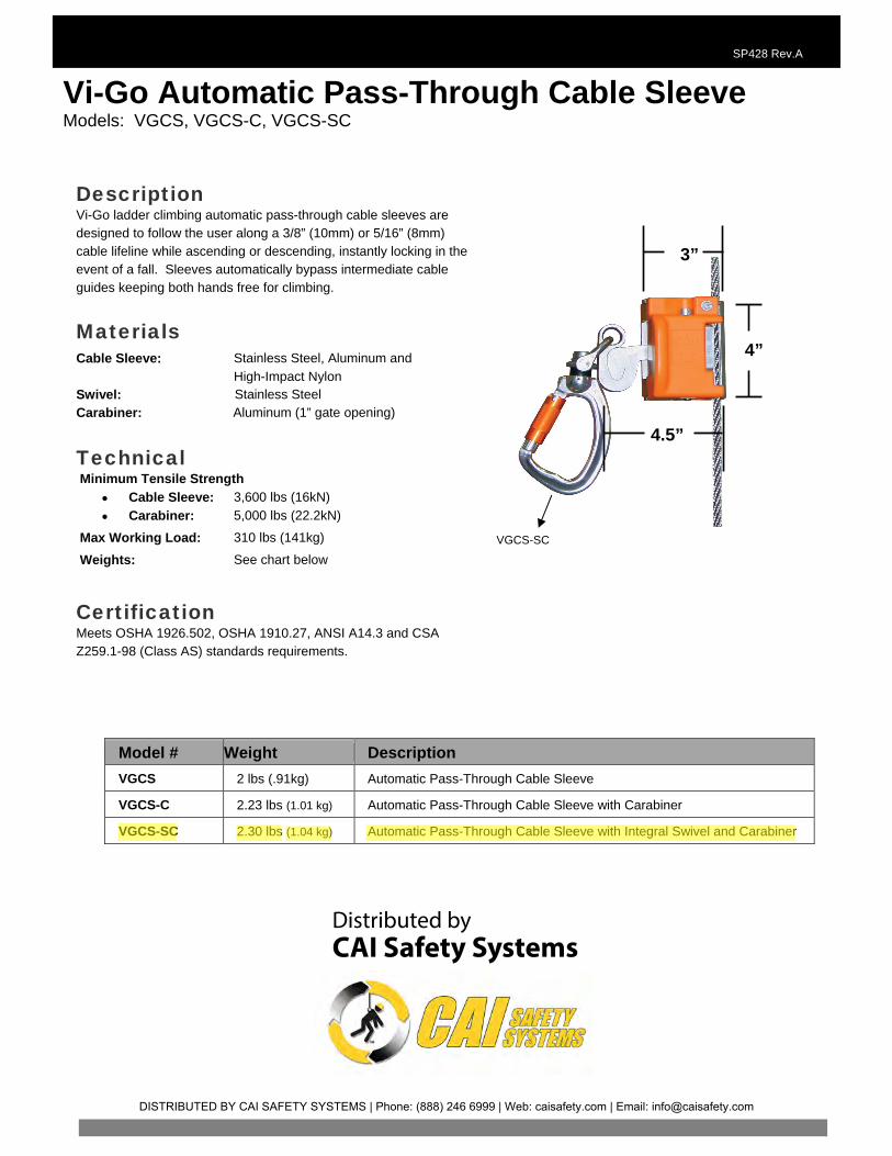
Vi-Go Automatic Pass-Through Cable Sleeve Models: VGCS, VGCS-C, VGCS-SC
SP428 Rev.A
Model # Weight Description VGCS 2 lbs (.91kg) Automatic Pass-Through Cable Sleeve
VGCS-C 2.23 lbs (1.01 kg) Automatic Pass-Through Cable Sleeve with Carabiner
VGCS-SC 2.30 lbs (1.04 kg) Automatic Pass-Through Cable Sleeve with Integral Swivel and Carabiner
Description Vi-Go ladder climbing automatic pass-through cable sleeves are designed to follow the user along a 3/8” (10mm) or 5/16” (8mm) cable lifeline while ascending or descending, instantly locking in the event of a fall. Sleeves automatically bypass intermediate cable guides keeping both hands free for climbing.
Materials
Cable Sleeve: Stainless Steel, Aluminum and High-Impact Nylon
Swivel: Stainless Steel Carabiner: Aluminum (1” gate opening)
Technical Minimum Tensile Strength
• Cable Sleeve: 3,600 lbs (16kN) • Carabiner: 5,000 lbs (22.2kN)
Max Working Load: 310 lbs (141kg)
Weights: See chart below
Certification Meets OSHA 1926.502, OSHA 1910.27, ANSI A14.3 and CSA Z259.1-98 (Class AS) standards requirements.
VGCS-SC
4”
3”
4.5”
Distributed byCAI Safety Systems
DISTRIBUTED BY CAI SAFETY SYSTEMS | Phone: (888) 246 6999 | Web: caisafety.com | Email: [email protected]
dmisquitta
Highlight
15
User Instruct ions - Engl ish
Cleaning and StorageBasic care of all Miller fall protection equipment will prolong the life of the unit and will contribute toward the performance of its vital safety function. Proper storage and maintenance after use are as important as cleansing the equipment of dirt, corrosives, or contaminants. Clean system components using a cloth dampened with water and mild soap or detergent and towel dry. Storage areas should be clean, dry and free of exposure to fumes or corrosive elements.
Servicing
A record log of all servicing and inspection dates for this system must be maintained. This system and all its components and devices must be withdrawn from service if subjected to fall arresting forces. Only original Miller fall protection replacement parts are approved for use in this system. Contact Honeywell Technical Service at 800.873.5242 if you have any questions.
8.0 Inspection and MaintenanceInspectionThe Vi-Go System is designed for today’s rugged work environments. To maintain its service life and high performance, all components should be inspected frequently. Visually inspect before each use. Regular inspection by a competent person for wear, damage or corrosion should be a part of your safety program. Replace equipment if any of the defective conditions explained in this manual are found.
System InspectionBefore each use, visually inspect for the following:
Inspect all components for physical damages, cracks, wear and corrosion.Check fasteners, bolts and pins for damages, cracks, wear and corrosion.Inspect the cable lifeline for cuts, frays, kinks, broken strands or other signs of unusual wearing patterns.
manual.Inspect for malfunctioning components, broken or missing springs and fasteners. [For replacement parts call: 800.873.5242]
Inspect cable sleeve, connector and full-body harness according to the manufacturer’s instructions.
DISTRIBUTED BY CAI SAFETY SYSTEMS | Phone: (888) 246 6999 | Web: caisafety.com | Email: [email protected]
45
P
PRELEVANTES
AM
MAINTENANCE
ENTRETIEN EFFECTUÉM
Approved by:Approuvé par:Aprobado por:
Approved by:Approuvé par:Aprobado por:
Approved by:Approuvé par:Aprobado por:
Approved by:Approuvé par:Aprobado por:
Approved by:Approuvé par:Aprobado por:
Approved by:Approuvé par:Aprobado por:
Approved by:Approuvé par:Aprobado por:
Approved by:Approuvé par:Aprobado por:
Approved by:Approuvé par:Aprobado por:
Approved by:Approuvé par:Aprobado por:
_________________________________________________
________________________________________________________
______________________________________________________
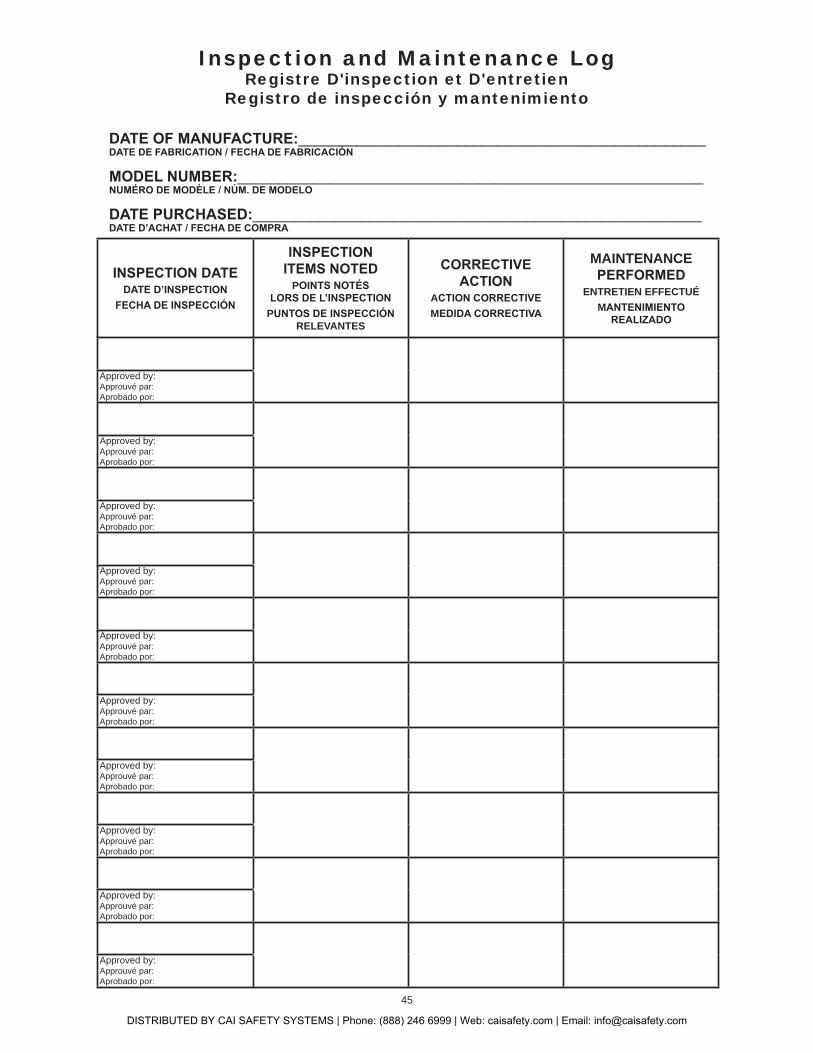
Inspection and Maintenance LogRegistre D'inspection et D'entretien
Registro de inspección y mantenimiento
DISTRIBUTED BY CAI SAFETY SYSTEMS | Phone: (888) 246 6999 | Web: caisafety.com | Email: [email protected]

47
MILLER®
At Honeywell Safety Products and its predecessors, we have been providing quality Miller brand fall protection equipment to millions of workers worldwide since 1945.
We sincerely believe that our fall protection equipment is the best in the world. Our products endure rigorous tests to ensure that the fall protection equipment you trust is manufactured
to the highest standards. Miller fall protection products are tested to withstand normal wear and tear,but are not indestructible and can be damaged by misuse.
Our Limited Lifetime Warranty does not apply to normal wear and tear or abusive treatment of the product.
In the unlikely event that you should discover defects in either workmanship or materials, under our Limited Lifetime Warranty, we will repair or replace the product at our expense.
If a replacement is necessary and your product is no longer available, a comparable product will be substituted. Should a product issue surface, contact us at 800.873.5242.
®
Honeywell Safety Products et ses prédécesseurs offrent les équipements antichute de marque Miller de qualité à des millions de travailleurs dans le monde entier depuis 1945.
GARANTIE LIMITÉE À VIE
Nous croyons sincèrement que notre équipement de protection contre les chutes est le meilleur au monde. Nos
garantie limitée à vie ne s’applique pas à l’usure normale ou à un usage abusif du produit.
Dans le cas peu probable où vous découvririez des défauts, soit de fabrication, soit de matériau, dans le cadre de notre garantie à vie, nous réparerons ou remplacerons le produit à nos frais.
En cas de remplacement, si votre produit n’est plus offert, vous recevrez un produit comparable. En cas de problème sur un produit, nous contacter au 800-873-5242.
®
En Honeywell Safety Products y sus predecesores, hemos estado brindando la calidad de la marca Miller en equipos de protección de caída a millones de trabajadores alrededor del mundo desde 1945.
Sinceramente creemos que su equipo de protección contra caídas es el mejor del mundo. Nuestros productos resisten rigurosas pruebas para garantizar que el equipo de protección contra caídas en el que usted confía está fabricado de
conformidad con las normas más elevadas. Los productos anticaídas Miller son sometidos a pruebas para que resistan el desgaste normal, pero no son indestructibles y su incorrecta utilización puede dañarlos.
Nuestra Garantía limitada de por vida no se aplica al desgaste normal ni al maltrato del producto.
En el poco probable caso de que usted descubriera defectos de mano de obra o materiales, por nuestra Garantía lim-itada de por vida, repararemos o sustituiremos el producto por cuenta nuestra. Si un reemplazo es necesario y nuestro
producto ya no está disponible, se lo sustituiremos por otro comparable. En caso de que surja un problema con el producto, contáctenos al 800.873.5242.
DISTRIBUTED BY CAI SAFETY SYSTEMS | Phone: (888) 246 6999 | Web: caisafety.com | Email: [email protected]

Distributed byCAI Safety Systems555 Monica CircleCorona, CA 92880Phone: 951.272.6999Toll-Free: 888.246.6999Fax: [email protected]: caisafety.com
Related Documents