REB500 Substation Automation Products Distributed busbar protection REB500 Operation Manual

Welcome message from author
This document is posted to help you gain knowledge. Please leave a comment to let me know what you think about it! Share it to your friends and learn new things together.
Transcript

REB500
Substation Automation Products
Distributed busbar protection REB500Operation Manual

Document ID: 1MRK 500 124-UENIssued: March 2016
Revision: -Product version: 8.2
© Copyright 2016 ABB. All rights reserved
Copyright
This document and parts thereof must not be reproduced or copied without writtenpermission from ABB, and the contents thereof must not be imparted to a thirdparty, nor used for any unauthorized purpose.
The software and hardware described in this document is furnished under a licenseand may be used or disclosed only in accordance with the terms of such license.
Trademarks
ABB and Relion are registered trademarks of the ABB Group. All other brand orproduct names mentioned in this document may be trademarks or registeredtrademarks of their respective holders.
Warranty
Please inquire about the terms of warranty from your nearest ABB representative.
ABB ABSubstation Automation ProductsSE-721 59 VästeråsSwedenTelephone: +46 (0) 21 32 50 00Facsimile: +46 (0) 21 14 69 18http://www.abb.com/substationautomation
Disclaimer
The data, examples and diagrams in this manual are included solely for the conceptor product description and are not to be deemed as a statement of guaranteedproperties. All persons responsible for applying the equipment addressed in thismanual must satisfy themselves that each intended application is suitable andacceptable, including that any applicable safety or other operational requirementsare complied with. In particular, any risks in applications where a system failureand /or product failure would create a risk for harm to property or persons(including but not limited to personal injuries or death) shall be the soleresponsibility of the person or entity applying the equipment, and those soresponsible are hereby requested to ensure that all measures are taken to exclude ormitigate such risks.
This document has been carefully checked by ABB but deviations cannot becompletely ruled out. In case any errors are detected, the reader is kindly requestedto notify the manufacturer. Other than under explicit contractual commitments, inno event shall ABB be responsible or liable for any loss or damage resulting fromthe use of this manual or the application of the equipment.
Conformity
This product complies with the directive of the Council of the EuropeanCommunities on the approximation of the laws of the Member States relating toelectromagnetic compatibility (EMC Directive 2004/108/EC) and concerningelectrical equipment for use within specified voltage limits (Low-voltage directive2006/95/EC). This conformity is the result of tests conducted by ABB inaccordance with the product standards EN 50263 and EN 60255-26 for the EMCdirective, and with the product standards EN 60255-1 and EN 60255-27 for the lowvoltage directive. The product is designed in accordance with the internationalstandards of the IEC 60255 series.
Safety information
The busbar protection system REB500 corresponds to the latest practices andguidelines and complies with the recognized safety rules. Nevertheless, care mustalways be taken to avoid danger.
Only use the busbar protection system when it is in perfect working order and instrict accordance with these operating instructions.
Dangerous situations can arise if the equipment is used improperly, especially ifthe user changes the configuration.
Live electrical equipment is in the immediate vicinity of REB500.Before working on the system, always ensure that it is impossible tocome into contact with, or even close to live parts.
The busbar protection system REB500 can initiate operation ofitems of electrical plant (circuit-breakers and isolators). Beforeworking on the equipment, always ensure that unwanted operationis inhibited or has no effect on persons or plant.
Strictly observe all safety precautions (interlocks, locks andblocking devices), especially those issued for the specific station.
Only properly authorized, professionally qualified andcorrespondingly trained personnel, who have also read andunderstood the operating instructions, may work on the system.
Dangerous voltages can occur on the connectors, even though theauxiliary voltage has been disconnected.
Non-observance can result in death, personal injury or substantialproperty damage.
Only a competent electrician is allowed to carry out the electricalinstallation.

National and local electrical safety regulations must always befollowed.
The frame of the IED has to be carefully earthed.
Whenever changes are made in the IED, measures should be takento avoid inadvertent tripping.
The IED contains components which are sensitive to electrostaticdischarge. Unnecessary touching of electronic components musttherefore be avoided.
Take care never to open the secondary circuits of CTs conductingcurrent.
There is a danger of contact with live parts when opening REB500cubicle doors.
Electrostatic discharge can destroy components in the equipment.
Other safety instructions pertaining to particular operations arecontained in the respective chapters of the operating instructions.
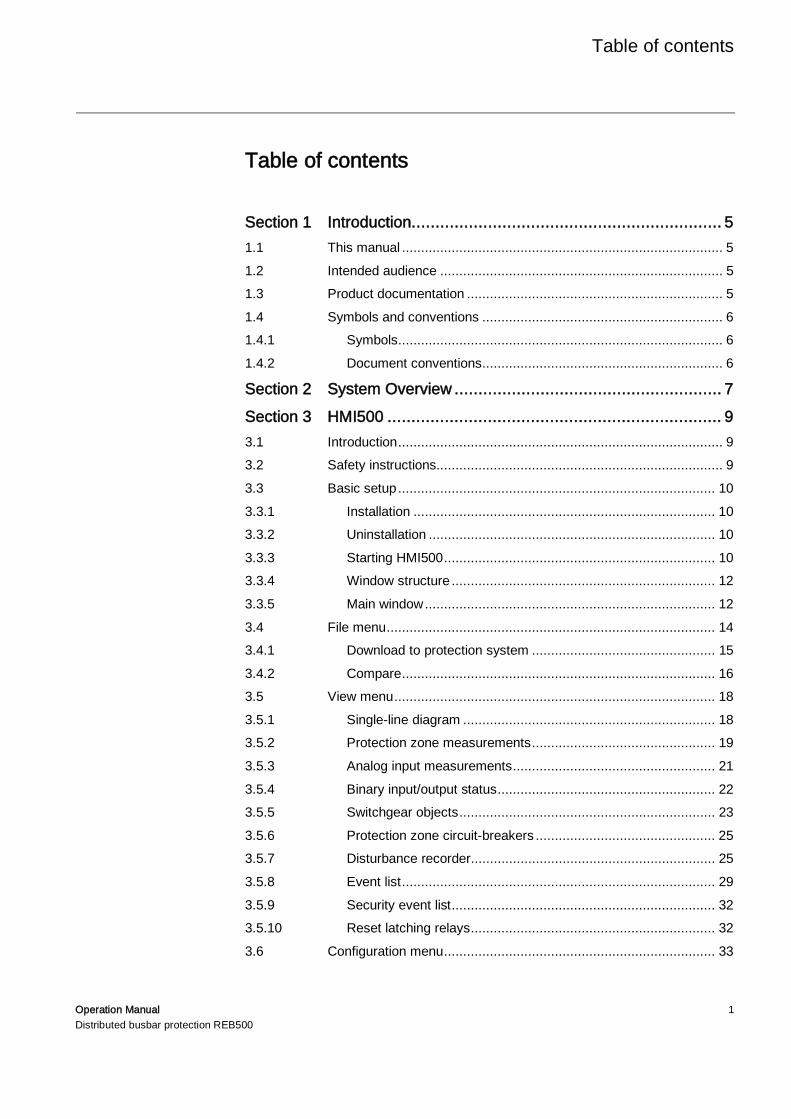
Table of contents
Operation Manual 1Distributed busbar protection REB500
Table of contents
Section 1 Introduction ................................................................. 51.1 This manual .................................................................................... 51.2 Intended audience .......................................................................... 51.3 Product documentation ................................................................... 51.4 Symbols and conventions ............................................................... 61.4.1 Symbols ..................................................................................... 61.4.2 Document conventions ............................................................... 6
Section 2 System Overview ........................................................ 7Section 3 HMI500 ...................................................................... 93.1 Introduction ..................................................................................... 93.2 Safety instructions ........................................................................... 93.3 Basic setup ................................................................................... 103.3.1 Installation ............................................................................... 103.3.2 Uninstallation ........................................................................... 103.3.3 Starting HMI500 ....................................................................... 103.3.4 Window structure ..................................................................... 123.3.5 Main window ............................................................................ 123.4 File menu ...................................................................................... 143.4.1 Download to protection system ................................................ 153.4.2 Compare .................................................................................. 163.5 View menu .................................................................................... 183.5.1 Single-line diagram .................................................................. 183.5.2 Protection zone measurements ................................................ 193.5.3 Analog input measurements ..................................................... 213.5.4 Binary input/output status ......................................................... 223.5.5 Switchgear objects ................................................................... 233.5.6 Protection zone circuit-breakers ............................................... 253.5.7 Disturbance recorder................................................................ 253.5.8 Event list .................................................................................. 293.5.9 Security event list ..................................................................... 323.5.10 Reset latching relays ................................................................ 323.6 Configuration menu ....................................................................... 33
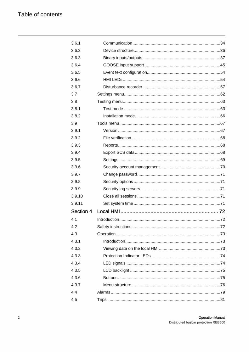
Table of contents
2 Operation ManualDistributed busbar protection REB500
3.6.1 Communication .........................................................................343.6.2 Device structure ........................................................................363.6.3 Binary inputs/outputs ................................................................373.6.4 GOOSE input support ...............................................................453.6.5 Event text configuration .............................................................543.6.6 HMI LEDs .................................................................................543.6.7 Disturbance recorder ................................................................573.7 Settings menu ................................................................................623.8 Testing menu .................................................................................633.8.1 Test mode ................................................................................633.8.2 Installation mode .......................................................................663.9 Tools menu ....................................................................................673.9.1 Version .....................................................................................673.9.2 File verification ..........................................................................683.9.3 Reports .....................................................................................683.9.4 Export SCS data .......................................................................683.9.5 Settings ....................................................................................693.9.6 Security account management ..................................................703.9.7 Change password .....................................................................713.9.8 Security options ........................................................................713.9.9 Security log servers ..................................................................713.9.10 Close all sessions .....................................................................713.9.11 Set system time ........................................................................71
Section 4 Local HMI ................................................................. 724.1 Introduction ....................................................................................724.2 Safety instructions..........................................................................724.3 Operation .......................................................................................734.3.1 Introduction ...............................................................................734.3.2 Viewing data on the local HMI ...................................................734.3.3 Protection Indicator LEDs..........................................................744.3.4 LED signals ..............................................................................744.3.5 LCD backlight ...........................................................................754.3.6 Buttons .....................................................................................754.3.7 Menu structure ..........................................................................764.4 Alarms ...........................................................................................794.5 Trips ..............................................................................................81
Table of contents
Operation Manual 3Distributed busbar protection REB500
Section 5 WebHMI ................................................................... 835.1 Introduction ................................................................................... 835.2 Accessing the WebHMI ................................................................. 83
Section 6 Troubleshooting ........................................................ 846.1 Safety Instructions ........................................................................ 846.2 List of faults and corrective actions ................................................ 856.2.1 Useful LEDs on the IEDs and switches..................................... 856.2.2 Faults during startup ................................................................ 866.2.3 Alarm and Event list entries ...................................................... 866.2.4 Optical fiber connections faults ................................................. 876.2.5 Electrical connection faults ....................................................... 886.3 Diagnostic (DIA) system - error handling ....................................... 88


1MRK 500 124-UEN Section 1Introduction
Operation Manual 5Distributed busbar protection REB500
Section 1 Introduction
1.1 This manual
The operation manual contains instructions on how to operate the IED once it hasbeen commissioned. The manual provides instructions for monitoring, controllingand setting the IED. The manual also provides trouble shouting instructions.
1.2 Intended audience
This manual addresses the operator, who operates the IED on a daily basis.
The operator must be trained in and have a basic knowledge of how to operateprotection equipment. The manual contains terms and expressions commonly usedto describe this kind of equipment.
1.3 Product documentation
For an introduction into REB500, it is recommended to study the Product Guideand/or the Application Manual.
Manual Document numberProduct Guide 1MRK 505 352-BEN
Application Manual 1MRK 505 349-UEN
Technical Manual 1MRK 505 350-UEN
Operation Manual 1MRK 500 124-UEN
Commissioning Manual 1MRK 505 351-UEN
Application ManualBay protection Functions
1MRK 505 353-UEN
Cyber Security Guideline 1MRK 511 373-UEN
Communication Protocol ManualIEC 61850
1MRK 511 370-UEN
Communication Protocol ManualIEC 60870-5-103
1MRK 511 371-UEN
Section 1 1MRK 500 124-UENIntroduction
6 Operation ManualDistributed busbar protection REB500
1.4 Symbols and conventions
1.4.1 Symbols
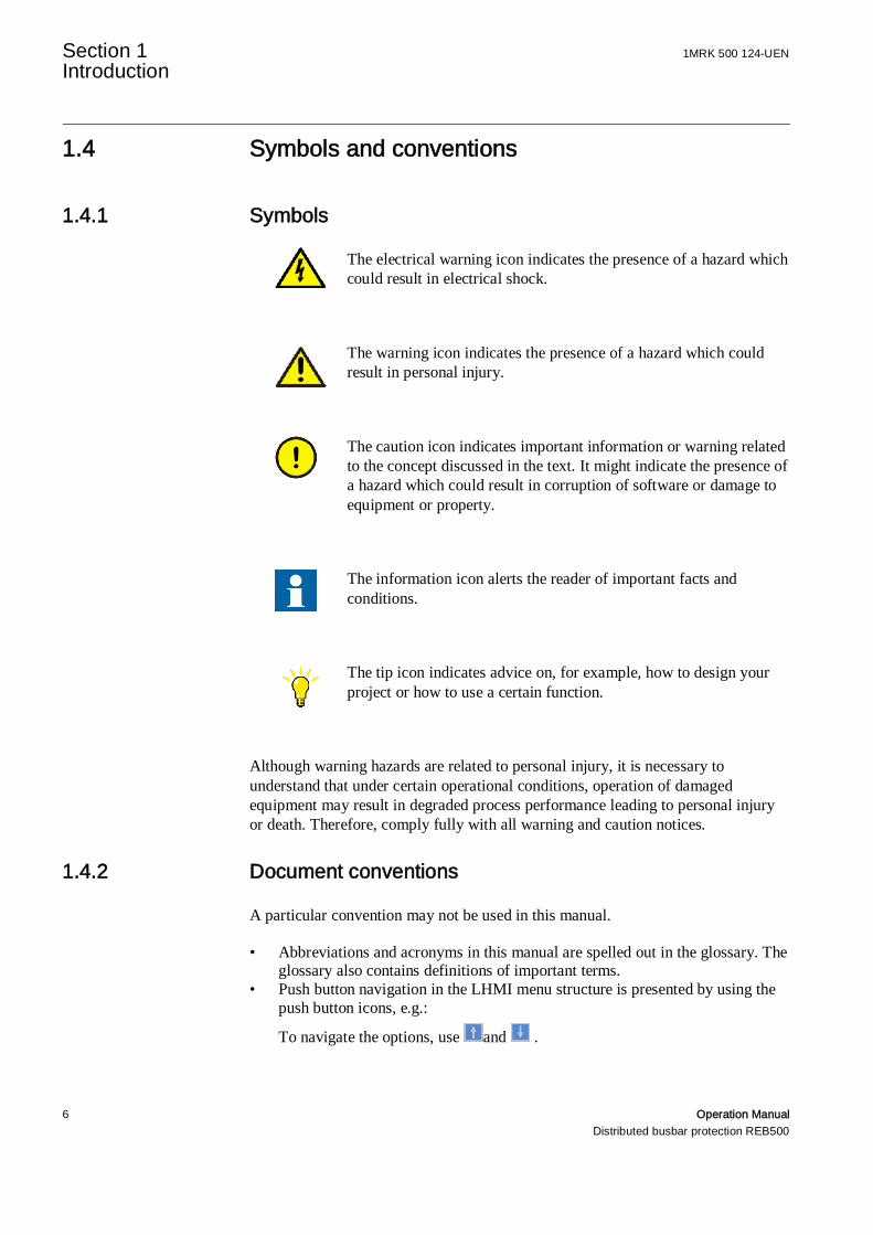
The electrical warning icon indicates the presence of a hazard whichcould result in electrical shock.
The warning icon indicates the presence of a hazard which couldresult in personal injury.
The caution icon indicates important information or warning relatedto the concept discussed in the text. It might indicate the presence ofa hazard which could result in corruption of software or damage toequipment or property.
The information icon alerts the reader of important facts andconditions.
The tip icon indicates advice on, for example, how to design yourproject or how to use a certain function.
Although warning hazards are related to personal injury, it is necessary tounderstand that under certain operational conditions, operation of damagedequipment may result in degraded process performance leading to personal injuryor death. Therefore, comply fully with all warning and caution notices.
1.4.2 Document conventions
A particular convention may not be used in this manual.
• Abbreviations and acronyms in this manual are spelled out in the glossary. Theglossary also contains definitions of important terms.
• Push button navigation in the LHMI menu structure is presented by using thepush button icons, e.g.:
To navigate the options, use and .
1MRK 500 124-UEN Section 2 System Overview
Operation Manual 7Distributed busbar protection REB500
Section 2 System Overview
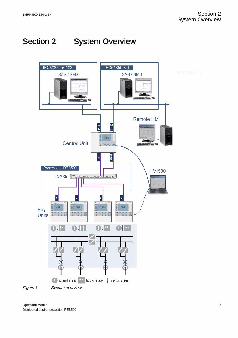
Figure 1 System overview
Section 2 1MRK 500 124-UENSystem Overview
8 Operation ManualDistributed busbar protection REB500
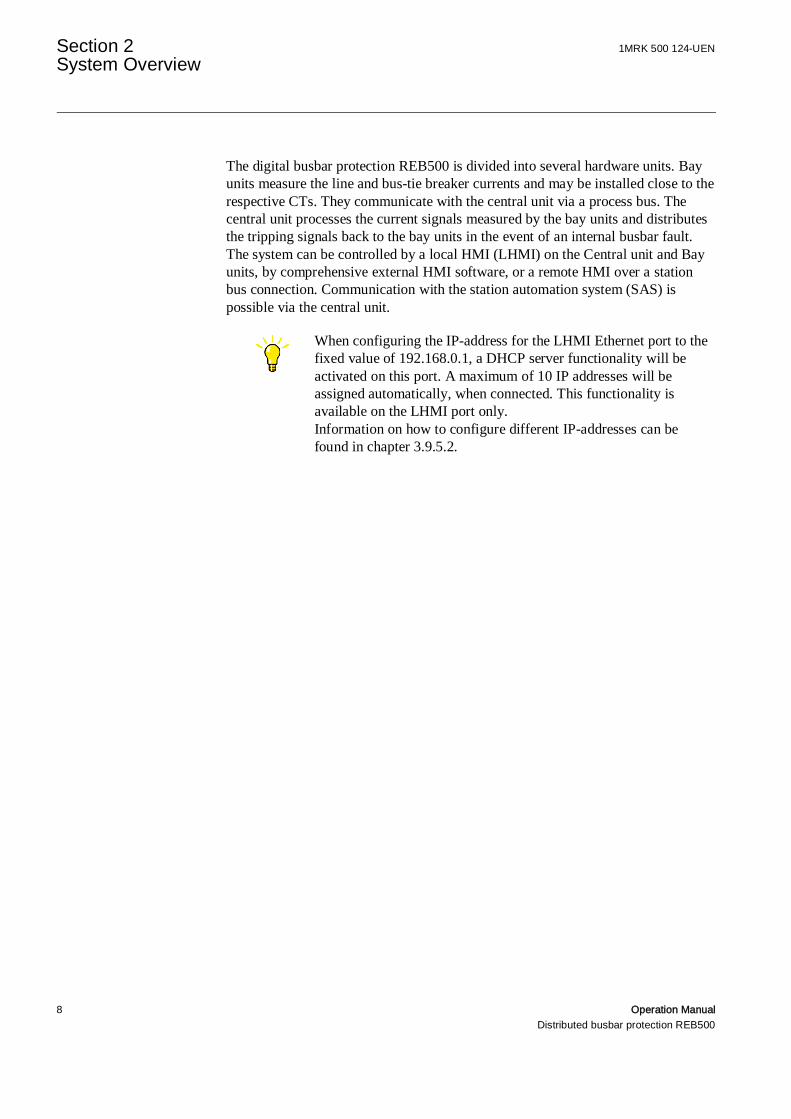
The digital busbar protection REB500 is divided into several hardware units. Bayunits measure the line and bus-tie breaker currents and may be installed close to therespective CTs. They communicate with the central unit via a process bus. Thecentral unit processes the current signals measured by the bay units and distributesthe tripping signals back to the bay units in the event of an internal busbar fault.The system can be controlled by a local HMI (LHMI) on the Central unit and Bayunits, by comprehensive external HMI software, or a remote HMI over a stationbus connection. Communication with the station automation system (SAS) ispossible via the central unit.
When configuring the IP-address for the LHMI Ethernet port to thefixed value of 192.168.0.1, a DHCP server functionality will beactivated on this port. A maximum of 10 IP addresses will beassigned automatically, when connected. This functionality isavailable on the LHMI port only.Information on how to configure different IP-addresses can befound in chapter 3.9.5.2.
1MRK 500 124-UEN Section 3HMI500
Operation Manual 9Distributed busbar protection REB500
Section 3 HMI500
3.1 Introduction
This section describes the human/machine interface (HMI) for the protectionsystems REB500. For a detailed explanation of signals and parameters see“Technical manual”. For a description of fault finding actions see Section 6 “Faultfinding”. For details on security settings see “Cyber security guideline”.
HMI500 is a convenient human-machine interface which permits the operator toview measurements and statuses, to set protection functions, to configure thesystem, to download the latter data to REB500, and to control the disturbancerecorder and event memory integrated in the system.
The data are transferred between the PC and REB500 via an Ethernet interfaceattached to the front of the central or bay units. The PC can be connected of thestation bus as well.
Any changes (e.g. settings, configuration etc.) made using HMI500are stored in a specific customer database (MS Access database file)on the PC and not in the protection system. The database then has tobe downloaded from the PC to the protection system (see Section3.4.1.).
3.2 Safety instructions
HMI500 permits circuit-breakers and isolators to be operated.Every program operation and the possible consequences must beconsidered carefully beforehand. If switching operations have to becarried out, the same precautions must be taken as when performingthem manually.
Earlier HMI500 versions are incompatible with Version 8.00 ofthe protection system software.
When the HMI500 software establishes communication with aREB500 system initially user must enter a password. For detailsabout security management, passwords and security options refer to“Security Deployment Guideline” (1KHL020774-Aen).
Section 3 1MRK 500 124-UENHMI500
10 Operation ManualDistributed busbar protection REB500
3.3 Basic setup
3.3.1 Installation
The human-machine interface program HMI500 is supplied on an installation CD.It can be installed on Windows XP or Windows 7.
Insert the CD-ROM in the drive. The CD Navigator starts then automatically.Should the auto-start function on your PC be disabled, select and run the programautostart.exe on the CD to start the CD-Navigator.
Select the preferred language and enter the HMI500 link which is placed under thesection “IED Software”. The software installation procedure should start now.During this installation procedure you are requested to read and confirm youracceptance of the license conditions.
The installation program proposes an installation directory. Either confirm theproposed directory or enter a desired one. Make sure that you have appropriateaccess rights to the respective directory. Clicking “Next” starts the installation.
An HMI500 directory and program icon “HMI500 x.xx ll” are created in theWindows Start menu, x.xx signifying the program version and ll the language.
3.3.2 Uninstallation
To uninstall HMI500 open the Windows control panel and select “Add/removeprograms“. In the list of programs select the entry for HMI500 and click on OK toremove the program.
3.3.3 Starting HMI500
The program screens in this section are based on a typicalapplication. Depending on the power system configuration and theoptions configured while engineering your system, certain menusmay be missing or the display appears different.
The first screen to appear after starting the operator program is the “System login”dialog:

1MRK 500 124-UEN Section 3HMI500
Operation Manual 11Distributed busbar protection REB500
Figure 2 System login dialog
The program can be run in a read only mode by ticking the “Read only” check box,i.e. the data can be viewed but not changed.
When the HMI500 software establishes communication with aREB500 system initially user must enter a password.
For details about security management, passwords and securityoptions refer to the “Security Deployment Guideline”.
HMI500 obtains the specific device data from a database in a file, which is storedboth in the PC and the protection system. Database files on the PC have theextension *.mdb.
Click on “OK” to continue start-up or on “Cancel” to close the program.
When you click on OK, HMI500 tests communication with the protection systemand starts in the on-line mode if communication can be established. Otherwise itstarts either in in off-line or simulation mode (see Section 3.9.5.).
Some of the dialogs used by the program are standard Windows dialogs, whoselanguage depends on the language setting of the operating system.
The database that was open during the last session opensautomatically. If no database was open before, select “Open” in the“File” menu and then the desired file. An error message is displayedif an attempt is made to open an incompatible file. An existing filein the protection system can also be opened using the “Upload”function in the “File” menu.
Section 3 1MRK 500 124-UENHMI500
12 Operation ManualDistributed busbar protection REB500
3.3.4 Window structure
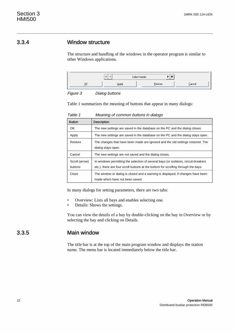
The structure and handling of the windows in the operator program is similar toother Windows applications.
Figure 3 Dialog buttons
Table 1 summarizes the meaning of buttons that appear in many dialogs:
Table 1 Meaning of common buttons in dialogsButton Description
OK The new settings are saved in the database on the PC and the dialog closes.
Apply The new settings are saved in the database on the PC and the dialog stays open.
Restore The changes that have been made are ignored and the old settings restored. The
dialog stays open.
Cancel The new settings are not saved and the dialog closes.
Scroll (arrow)buttons
In windows permitting the selection of several bays (or isolators, circuit-breakersetc.), there are four scroll buttons at the bottom for scrolling through the bays.
Close The window or dialog is closed and a warning is displayed, if changes have beenmade which have not been saved.
In many dialogs for setting parameters, there are two tabs:
• Overview: Lists all bays and enables selecting one.• Details: Shows the settings.
You can view the details of a bay by double-clicking on the bay in Overview or byselecting the bay and clicking on Details.
3.3.5 Main window
The title bar is at the top of the main program window and displays the stationname. The menu bar is located immediately below the title bar.

1MRK 500 124-UEN Section 3HMI500
Operation Manual 13Distributed busbar protection REB500
Table 2 Main menu itemsMenu Item Description
File Permits databases to be opened and saved and a database to be uploaded fromthe protection or downloaded to it.
View Contains menu items for viewing the plant diagram, the measurements of eachprotection zone, inputs and outputs, switchgear statuses, the event list and anytripping that has taken place.
Configuration Concerns the definition of the licensed bay protection functions, the communicationparameters, the binary input/ output configuration, the event text configuration, theconfiguration of the LEDs on the local HMI and the disturbance recorderconfiguration.
Settings Setting the operating values for the various protection functions, the parameters ofthe primary system objects (e.g. current transformers, voltage transformers, etc.)and the system parameters including the system behavior.
Testing Enabling/disabling either the test or installation mode.
Tools Functions for editing data file versions, producing reports, exporting SCScommunication data, changing passwords, setting of security options and securityaccount management, selecting operator program options and setting the systemtime.
Windows Provides facilities for arranging open windows (cascade, tile vertically, tilehorizontally, arrange icons).
? (Help) Information details of the software version.
Status information is displayed on the bar at the bottom of the main window asshown in Figure 4.
Field :1 2 3 4 5 6 7 8
Figure 4 Status bar
Table 3 Status bar contentField Content Description
1 Configurator indicates that configurator mode is active (no target communicationpossible)
Operator indicates that operator mode is active (target communication possible)
2 Online Successfully established contact with the protection system.
Offline No connection to protection system.
Simulation All the functions can be executed without being connected to a protectiondevice. Random values are generated when viewing protection unit data,e.g. event lists or measurements. Simulated faults can also be viewed.

Section 3 1MRK 500 124-UENHMI500
14 Operation ManualDistributed busbar protection REB500
3 HMI:[IP:Port]
Active Ethernet interface (on the device front), the IP address and the portconnected for the target communication
LAN0:[IP:Port]
Active Ethernet interface communication over station bus, the IP addressand the port connected for the target communication
4 Edit Permits settings to be saved in a file or downloaded to the protectionsystem.
Read-Only It is only possible to read data.
5 Test Test generator is activated.
Test generator not active
6 Install Installation mode is active (debug mode is inactive)
Install/Debug Installation mode and Debug mode are active
Debug Debug mode is active (Installation mode is inactive)
7 <Setfile> Path and name of the currently open setfile.
8 <action> short message of an ongoing action
3.4 File menu
Table 4 summarizes the options available in this menu. The subsequent subsectionsdescribe the menu items “Download to protection system…” and “Compare…” ingreater detail.
Table 4 Menu items in menu FileMenu Item Description
Open… Opens a database file stored on the computer’s file system.
Save as… Saves the currently open database to the computer’s file system.
Upload fromprotection system…
Saves a database from the protection system to the computer’s file system.
Download toprotection system…
Sends a database file from the computer’s file system to the protectionsystem.
Compare… Compares a database file on the computer’s file system to the database ofthe protection system or to another database file on the computer’s filesystem.
Exit Terminates the program; displays a warning if there are changes that havenot been saved. You then have the choice of saving or discarding them.
1MRK 500 124-UEN Section 3HMI500
Operation Manual 15Distributed busbar protection REB500
3.4.1 Download to protection system
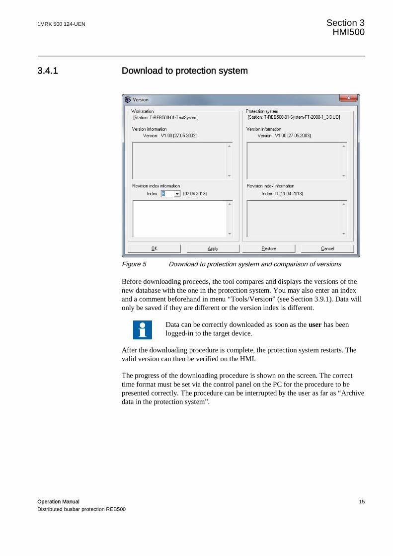
Figure 5 Download to protection system and comparison of versions
Before downloading proceeds, the tool compares and displays the versions of thenew database with the one in the protection system. You may also enter an indexand a comment beforehand in menu “Tools/Version” (see Section 3.9.1). Data willonly be saved if they are different or the version index is different.
Data can be correctly downloaded as soon as the user has beenlogged-in to the target device.
After the downloading procedure is complete, the protection system restarts. Thevalid version can then be verified on the HMI.
The progress of the downloading procedure is shown on the screen. The correcttime format must be set via the control panel on the PC for the procedure to bepresented correctly. The procedure can be interrupted by the user as far as “Archivedata in the protection system”.
Section 3 1MRK 500 124-UENHMI500
16 Operation ManualDistributed busbar protection REB500
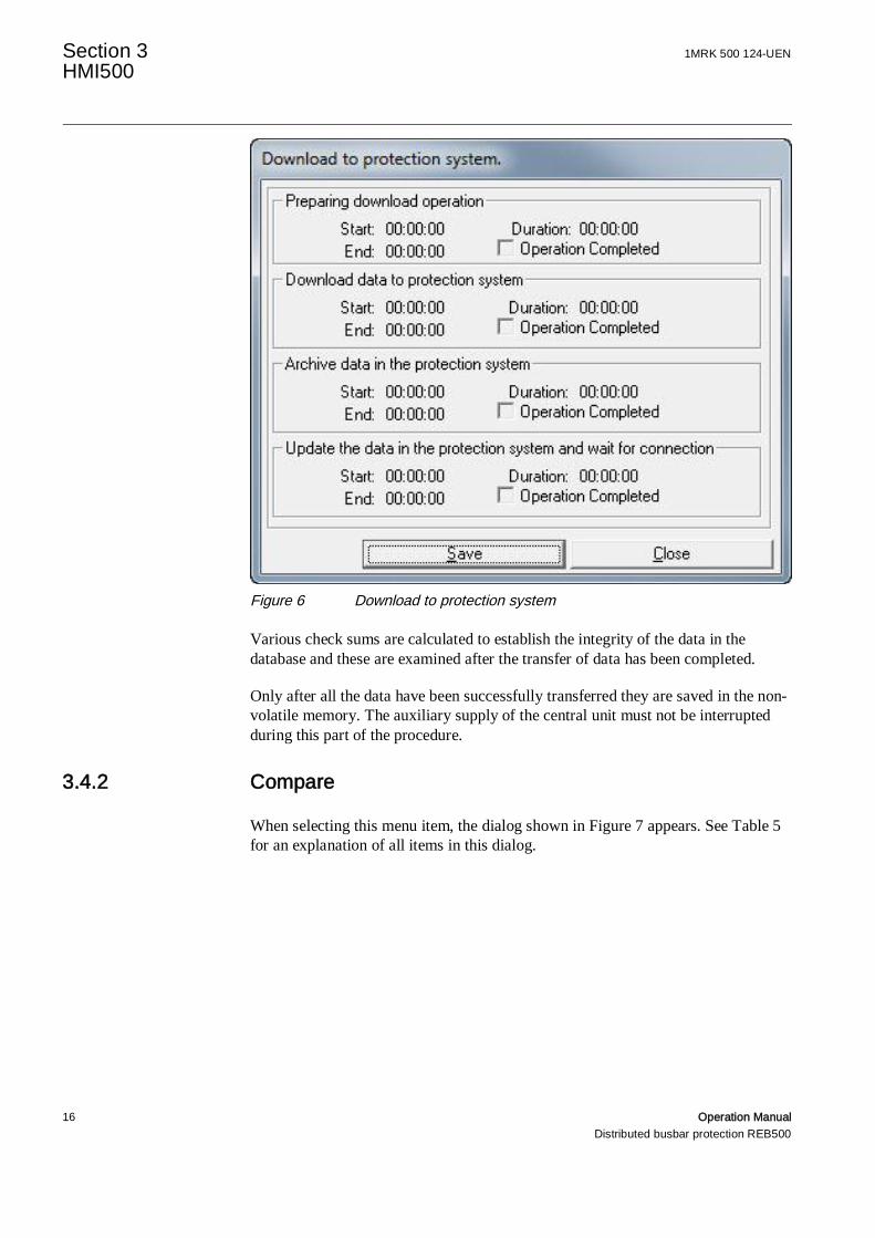
Figure 6 Download to protection system
Various check sums are calculated to establish the integrity of the data in thedatabase and these are examined after the transfer of data has been completed.
Only after all the data have been successfully transferred they are saved in the non-volatile memory. The auxiliary supply of the central unit must not be interruptedduring this part of the procedure.
3.4.2 Compare
When selecting this menu item, the dialog shown in Figure 7 appears. See Table 5for an explanation of all items in this dialog.

1MRK 500 124-UEN Section 3HMI500
Operation Manual 17Distributed busbar protection REB500
Figure 7 Comparison of system databases
Table 5 Dialog items of “Compare system database”Dialog Item Description
Second database isstored at PC
Compares the currently open system database with another database inthe PC, which can be chosen by clicking on “Select file…“.
Second database isat target
Compares the currently open system database with the database in theprotection system. For a faster but less detailed check, tick “Only comparechecksum”.
Show onlydifferences
Limits the scope of the report to the differences actually found.
Limit number ofdifferences
The number entered here determines the number of differences that canbe found before the current comparison operation is aborted.
Show pre-engineering changesonly for feeders andswitchgear objects
When this box is checked (default setting), the comparison is restricted todetermining whether changes have taken place in relation to the pre-engineering data for bays and switchgear. Generally, the default settingsshould be retained as otherwise the number of differences that will bediscovered increases considerably (events, signals etc., are then alsotaken into account)
Write log file The results of the comparison are stored in a file.
Compare… Starts the comparison operation
Section 3 1MRK 500 124-UENHMI500
18 Operation ManualDistributed busbar protection REB500
3.5 View menu
3.5.1 Single-line diagram
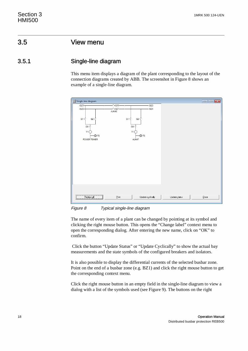
This menu item displays a diagram of the plant corresponding to the layout of theconnection diagrams created by ABB. The screenshot in Figure 8 shows anexample of a single-line diagram.
Figure 8 Typical single-line diagram
The name of every item of a plant can be changed by pointing at its symbol andclicking the right mouse button. This opens the “Change label” context menu toopen the corresponding dialog. After entering the new name, click on “OK” toconfirm.
Click the button “Update Status” or “Update Cyclically” to show the actual baymeasurements and the state symbols of the configured breakers and isolators.
It is also possible to display the differential currents of the selected busbar zone.Point on the end of a busbar zone (e.g. BZ1) and click the right mouse button to getthe corresponding context menu.
Click the right mouse button in an empty field in the single-line diagram to view adialog with a list of the symbols used (see Figure 9). The buttons on the right
1MRK 500 124-UEN Section 3HMI500
Operation Manual 19Distributed busbar protection REB500
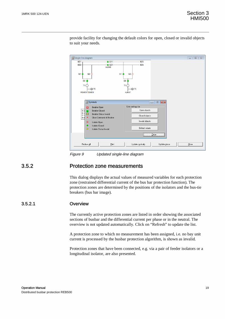
provide facility for changing the default colors for open, closed or invalid objectsto suit your needs.
Figure 9 Updated single-line diagram
3.5.2 Protection zone measurements
This dialog displays the actual values of measured variables for each protectionzone (restrained differential current of the bus bar protection function). Theprotection zones are determined by the positions of the isolators and the bus-tiebreakers (bus bar image).
3.5.2.1 Overview
The currently active protection zones are listed in order showing the associatedsections of busbar and the differential current per phase or in the neutral. Theoverview is not updated automatically. Click on “Refresh” to update the list.
A protection zone to which no measurement has been assigned, i.e. no bay unitcurrent is processed by the busbar protection algorithm, is shown as invalid.
Protection zones that have been connected, e.g. via a pair of feeder isolators or alongitudinal isolator, are also presented.

Section 3 1MRK 500 124-UENHMI500
20 Operation ManualDistributed busbar protection REB500
Figure 10 Overview dialog for protection zone measurements
3.5.2.2 Detailed view
The feeders assigned to individual protection zones are listed in the detailed viewsof the relevant zones. The differential current, the restraint current and the stabilityfactor are also displayed.

1MRK 500 124-UEN Section 3HMI500
Operation Manual 21Distributed busbar protection REB500
Figure 11 Detailed view of measurements per zone
3.5.3 Analog input measurements
The bay units and their labels are listed in the overview dialog.
To display the values of measured variables select a device (row) and click on“Open measurements window”, or double-click on the device (row). Up to eightmeasurement windows can be open at the same time. “Arrange windows” arrangesthe windows below each other.
The display can be updated either manually by clicking on “Update measurement”or automatically by clicking on “Update cyclically”. This updates all openmeasurement windows.
A warning appears in the measurement window if measurements cannot beobtained correctly. Closing the overview window closes all the measurementwindows as well.
For the selected bay unit, the phase-angles as well as the analog measurements (seeFigure 12) are displayed. The currently valid reference channel, i.e. reference pointfor displaying phase-angles, is highlighted yellow. The user can change thereference channel by double-clicking on the desired one. The phase-angle displayis not available on the other types of bay unit.
Section 3 1MRK 500 124-UENHMI500
22 Operation ManualDistributed busbar protection REB500
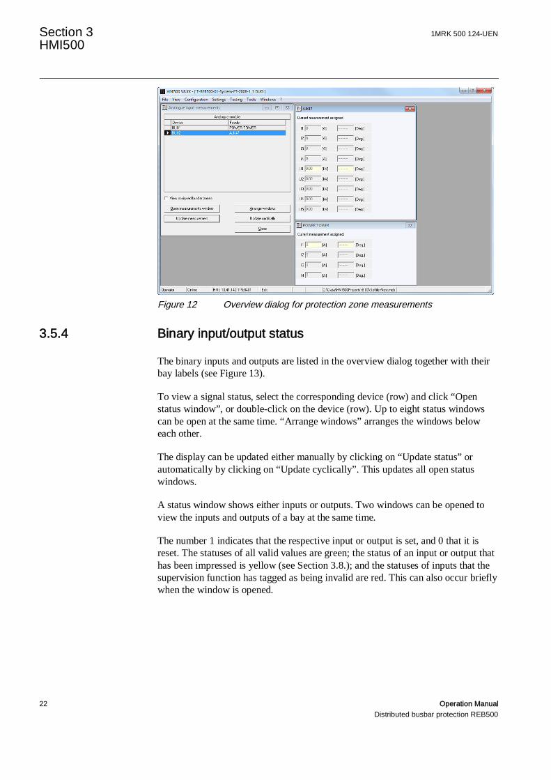
Figure 12 Overview dialog for protection zone measurements
3.5.4 Binary input/output status
The binary inputs and outputs are listed in the overview dialog together with theirbay labels (see Figure 13).
To view a signal status, select the corresponding device (row) and click “Openstatus window”, or double-click on the device (row). Up to eight status windowscan be open at the same time. “Arrange windows” arranges the windows beloweach other.
The display can be updated either manually by clicking on “Update status” orautomatically by clicking on “Update cyclically”. This updates all open statuswindows.
A status window shows either inputs or outputs. Two windows can be opened toview the inputs and outputs of a bay at the same time.
The number 1 indicates that the respective input or output is set, and 0 that it isreset. The statuses of all valid values are green; the status of an input or output thathas been impressed is yellow (see Section 3.8.); and the statuses of inputs that thesupervision function has tagged as being invalid are red. This can also occur brieflywhen the window is opened.
1MRK 500 124-UEN Section 3HMI500
Operation Manual 23Distributed busbar protection REB500
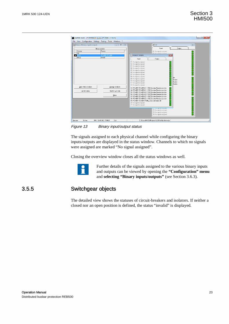
Figure 13 Binary input/output status
The signals assigned to each physical channel while configuring the binaryinputs/outputs are displayed in the status window. Channels to which no signalswere assigned are marked “No signal assigned”.
Closing the overview window closes all the status windows as well.
Further details of the signals assigned to the various binary inputsand outputs can be viewed by opening the “Configuration” menuand selecting “Binary inputs/outputs” (see Section 3.6.3).
3.5.5 Switchgear objects
The detailed view shows the statuses of circuit-breakers and isolators. If neither aclosed nor an open position is defined, the status “invalid” is displayed.

Section 3 1MRK 500 124-UENHMI500
24 Operation ManualDistributed busbar protection REB500
Figure 14 Switchgear objects

1MRK 500 124-UEN Section 3HMI500
Operation Manual 25Distributed busbar protection REB500
3.5.6 Protection zone circuit-breakers
The detailed view shows all the circuit-breakers belonging to the respectiveprotection zone.
Figure 15 Protection zone circuit-breakers, detailed view
These circuit-breakers are intertripped, for example, in the event of a busbar faultin the respective protection zone.
3.5.7 Disturbance recorder
A disturbance recorder is integrated in every bay unit and in the central unit of thesystem. In the bay units, it records the current measurements, the voltagemeasurements and up to 32 binary input and output signals. In the central unit, itrecords the differential and restraint currents of every buszone and up to 64 binaryoutput signals. Up to 40 recording periods are supported (depending on the selectedsample rate and recording time).

Section 3 1MRK 500 124-UENHMI500
26 Operation ManualDistributed busbar protection REB500
3.5.7.1 Overview
Figure 16 Disturbance recorder overview
This tab displays the number of records and the current status of the devices. Thecolumn “Bays” indicates the bay names of the individual records. The record of thecentral unit can be seen from the “bays” entry “CU01”. See Table 6 for anexplanation of the device statuses.
Table 6 Disturbance recorder statusesStatus Description
Ready Disturbance recorder is ready to record disturbances.
Recording A record procedure is in progress.
Not ready The disturbance recorder has to be restarted in the detailed view of the bay
Full memory Disturbance recorder memory is fullNot available Disturbance recorder function is not active for the bay
1MRK 500 124-UEN Section 3HMI500
Operation Manual 27Distributed busbar protection REB500
Press “Shift” and click on the desired fields to select several fields at once. Byclicking on the respective buttons below, you can apply a command to all selectedbay units at once:
1. Open detailed views (button “Open window”)2. Start recording3. Upload records from selected disturbance recorders (Transfer disturbance
records to computer)4. Delete all disturbance records
3.5.7.2 Upload disturbance recorder records
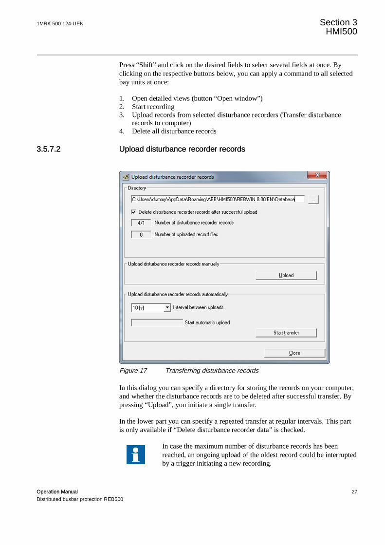
Figure 17 Transferring disturbance records
In this dialog you can specify a directory for storing the records on your computer,and whether the disturbance records are to be deleted after successful transfer. Bypressing “Upload”, you initiate a single transfer.
In the lower part you can specify a repeated transfer at regular intervals. This partis only available if “Delete disturbance recorder data” is checked.
In case the maximum number of disturbance records has beenreached, an ongoing upload of the oldest record could be interruptedby a trigger initiating a new recording.
Section 3 1MRK 500 124-UENHMI500
28 Operation ManualDistributed busbar protection REB500
3.5.7.3 Detailed view (“Open window”)
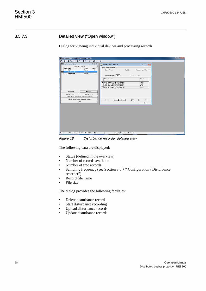
Dialog for viewing individual devices and processing records.
Figure 18 Disturbance recorder detailed view
The following data are displayed:
• Status (defined in the overview)• Number of records available• Number of free records• Sampling frequency (see Section 3.6.7 “ Configuration / Disturbance
recorder”)• Record file name• File size
The dialog provides the following facilities:
• Delete disturbance record• Start disturbance recording• Upload disturbance records• Update disturbance records
1MRK 500 124-UEN Section 3HMI500
Operation Manual 29Distributed busbar protection REB500
3.5.7.4 Disturbance recorder file (Detailed view / Upload )
The disturbance records are available in a zipped Comtrade file. The involveddisturbance recorder files has the naming convention
DRyyyyMMddhhmmssfff_aaa_nnnnn.ZIP
Table 7 Disturbance file namesItem Descriptionyyyy Year of the recording (Trigger time)MM Month of the recording (Trigger time)dd Day of the recording (Trigger time)hh Hour of the recording (Trigger time)mm Minute of the recording (Trigger time)ss Second of the recording (Trigger time)fff Miliseconds of the recording (Trigger time)aaa Station number (1-999)nnnnn Fault number (0-65535)
The name of the file can be changed if the records are transferred manually.
3.5.8 Event list
Protection system events are shown in chronological order. By correspondinglysetting the event filter, just protection events, system events or test events can beviewed separately. Events with an invalid time tag can be excluded from thedisplay. You can choose between “User-defined” and “System-defined” eventtexts.

Section 3 1MRK 500 124-UENHMI500
30 Operation ManualDistributed busbar protection REB500
Figure 19 Event list
The central unit event list has a maximum length of 1000 records; the bay units100. In the event of a supply failure, the events stored in the REB500 central unitremain intact for at least 24 hours.
3.5.8.1 Classification of events
The REB500 system includes two different event lists, the “normal” and the“extended” events. The HMI view “Event List” enables the selection of therespective class (see Figure 19 / Selection “Event list selection”)
normal:
The “normal” event list shows mainly protection and system events includingdiagnosis events in case of major/minor errors which are relevant for the user. Fornormal operation of a REB500 system it is recommended to use the 'normal eventlist' view.
extended:
The extended event list shows further events for diagnosis and error cause analysis.The vast majority of minor errors falls into this group. The “extended event list”view can be helpful for error diagnosis and support activities.
mixed:
The mixed event list shows both, the entries of the “normal” and the “extended”view.

1MRK 500 124-UEN Section 3HMI500
Operation Manual 31Distributed busbar protection REB500
3.5.8.2 Load events
The protection system has an event memory for every unit (central unit and bayunits).
To upload the latest events to the PC, open the “View” menu and select “Eventlist”. This opens the “Event list” dialog (HMI500 must be in the on-line mode).Click on the “Refresh“ button to upload the events. The protection system storesthe events until they are explicitly deleted.
The list viewed on the PC is refreshed either on command or cyclically.
There is no indication should the event memory overflow before the events havebeen uploaded. The events are updated as determined by the system responsesetting (see “Technical Reference Manual”).
The following information is shown for every event:
• Type of event• P = Protection function event• S = System event• T = Test generator event
• Date event occurred• Time event occurred• Time tag valid (yes / no)• Source of event with application device ID in the format
FFFAAAAAA (e.g. BPD000011):• FFF: English function designation• AAAAAA: Address of the hardware unit that generated the event.
The source data are important for locating hardware defects.
• Text as entered via “Configuration/Binary inputs/outputs” (user defined) oralternatively, the name assigned by the system (system defined)
• Value, e.g. ON or OFF.
The width of the columns can be adjusted by dragging the border with the mouse inthe table header.
Providing a printer is connected to the PC, you can print the event list by clickingon “Print”. The event list can be saved in a text file on the PC with the aid of“ASCII export”.

Section 3 1MRK 500 124-UENHMI500
32 Operation ManualDistributed busbar protection REB500
3.5.8.3 Deleting events
An event is marked by clicking on it. Several events can be marked by holding themouse button and moving the pointer over them. Clicking in the blank field at thetop left of the window (next to “Type”) marks all the events in the list.
3.5.8.4 Deleting the PC list
Single events, groups of events or all events can be deleted. Mark events you wishto delete and click on “Delete PC list”. Deleting can take several seconds.
3.5.8.5 Deleting the system list
All the events stored in the protection system are deleted.
3.5.8.6 Deleting events that have been viewed
All the protection events viewed since opening the window are deleted.
3.5.8.7 System events when starting
A number of system signals that are generated when starting the system arerecorded as events. Up to the instant that system clocks are automaticallysynchronized, events may have an incorrect date and time. These events are notdisplayed if “Only events with a valid time tag” was selected.
3.5.9 Security event list
It is possible to upload the security events stored on the protection system devices.The security events can be uploaded by using the “Refresh” button or using the“Update cyclically” button to get the data every four seconds from the targetdevice. For details see “Cyber security guideline”
3.5.10 Reset latching relays
All latched signals are reset and the corresponding display on the local control unitis deleted.
Figure 20 Reset latching relays
1MRK 500 124-UEN Section 3HMI500
Operation Manual 33Distributed busbar protection REB500
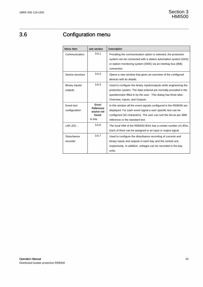
3.6 Configuration menu
Menu Item see section Description
Communication 3.6.1 Providing the communication option is selected, the protectionsystem can be connected with a station automation system (SAS)or station monitoring system (SMS) via an interbay bus (IBB)connection.
Device structure 3.6.2 Opens a new window that gives an overview of the configureddevices with its details.
Binary inputs/outputs
3.6.3 Used to configure the binary inputs/outputs while engineering theprotection system. The data entered are normally provided in thequestionnaire filled in by the user. This dialog has three tabs:Overview, Inputs, and Outputs.
Event textconfiguration
Error!Referencesource not
found.In this
In this window all the event signals configured in the REB500 aredisplayed. For each event signal a user specific text can beconfigured (32 characters). The user can sort the list as per ABBreference or the standard text.
LMI LED… 3.6.6 The local HMI of the REB500 IEDs has a certain number of LEDs.Each of them can be assigned to an input or output signal.
Disturbancerecorder
3.6.7 Used to configure the disturbance recording of currents andbinary inputs and outputs in each bay and the central unit,respectively. In addition, voltages can be recorded in the bayunits.

Section 3 1MRK 500 124-UENHMI500
34 Operation ManualDistributed busbar protection REB500
3.6.1 Communication
3.6.1.1 SCS Configuration
Figure 21 Configuration / Communication – SCS Configuration
This dialog contains station control system (SCS) settings to define the interbaybus (IBB) connection. For communication details refer to the ”CommunicationProtocol Manual”.
1MRK 500 124-UEN Section 3HMI500
Operation Manual 35Distributed busbar protection REB500
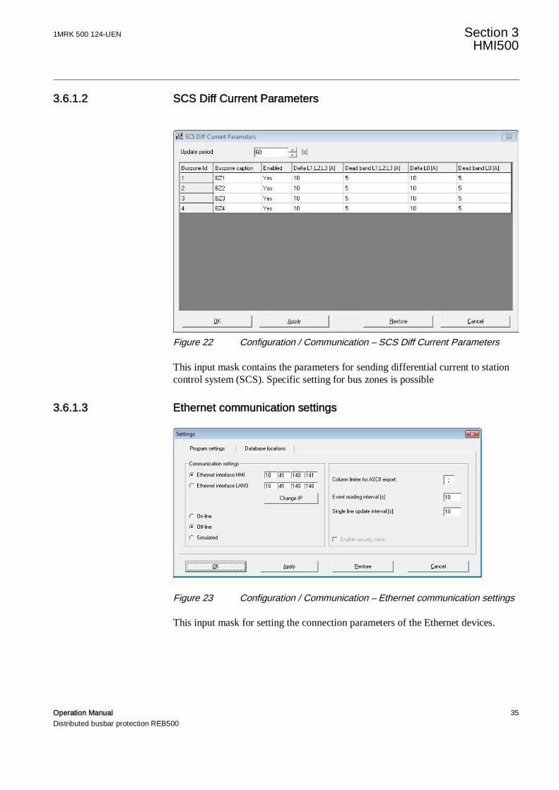
3.6.1.2 SCS Diff Current Parameters
Figure 22 Configuration / Communication – SCS Diff Current Parameters
This input mask contains the parameters for sending differential current to stationcontrol system (SCS). Specific setting for bus zones is possible
3.6.1.3 Ethernet communication settings
Figure 23 Configuration / Communication – Ethernet communication settings
This input mask for setting the connection parameters of the Ethernet devices.

Section 3 1MRK 500 124-UENHMI500
36 Operation ManualDistributed busbar protection REB500
3.6.2 Device structure
The device structure is configured by ABB when engineering the system. Thisdialog is only for information as the configuration cannot be changed.
The “Overview” tab lists the central unit and all the bay units along with theirdevice label and device type.
Figure 24 Configuration / Device structure

1MRK 500 124-UEN Section 3HMI500
Operation Manual 37Distributed busbar protection REB500
3.6.3 Binary inputs/outputs
3.6.3.1 Overview
Figure 25 Configuration / Binary module - Overview
The overview tab shows a list with all configured devices providing binaryinputs/outputs. See Table 8 for an explanation of the columns.
Table 8 Binary inputs/outputs overview columnsColumn Description
ABB ref. Internal designation for the bay or central unit
Feeder in which the bay unit is located, user’s label for the bay
Device IED device label
Module IED device type
For further information about the input or output configuration refer to 3.6.3.2 or3.6.3.5.
3.6.3.2 Inputs
This tab contains another two sub tabs “Overview” and “Details”. The additionalbuttons “New signal”, “Delete” and “OC event config” are enabled when the“Overview” tab is active. When the “Details” tab is active only the “New signal”button is enabled.
Section 3 1MRK 500 124-UENHMI500
38 Operation ManualDistributed busbar protection REB500
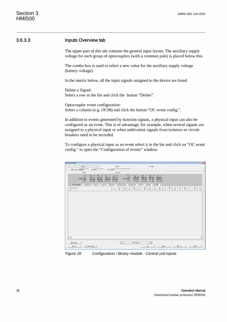
3.6.3.3 Inputs Overview tab
The upper part of this tab contains the general input layout. The auxiliary supplyvoltage for each group of optocouplers (with a common pole) is placed below this.
The combo box is used to select a new value for the auxiliary supply voltage(battery voltage).
In the matrix below, all the input signals assigned to the device are listed.
Delete a Signal:Select a row in the list and click the button “Delete”.
Optocoupler event configuration:Select a column (e.g. OC08) and click the button “OC event config.”.
In addition to events generated by function signals, a physical input can also beconfigured as an event. This is of advantage, for example, when several signals areassigned to a physical input or when ambivalent signals from isolators or circuit-breakers need to be recorded.
To configure a physical input as an event select it in the list and click on “OC eventconfig.” to open the “Configuration of events” window.
Figure 26 Configuration / Binary module - Central unit inputs
1MRK 500 124-UEN Section 3HMI500
Operation Manual 39Distributed busbar protection REB500
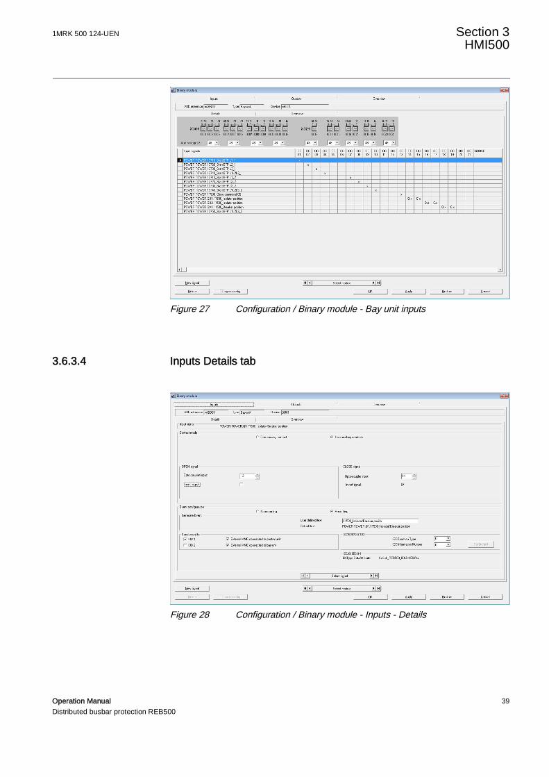
Figure 27 Configuration / Binary module - Bay unit inputs
3.6.3.4 Inputs Details tab
Figure 28 Configuration / Binary module - Inputs - Details
Section 3 1MRK 500 124-UENHMI500
40 Operation ManualDistributed busbar protection REB500
Signal allocation
The “Details” dialog provides facility for allocating optocoupler inputs to thelogical input signals and the event memory of every input/output.
The abbreviations C.x and O.x denote the CLOSE and OPEN auxiliary contacts onthe isolator or circuit-breaker respectively as they appear in the “Details” dialog.Where an isolator or a circuit-breaker is only equipped with a single auxiliarycontact, the “One auxiliary contact” mode must be selected.
This mode is not recommended because the status of the isolator or circuit-breakercannot be properly monitored with just one auxiliary contact.
The signals are configured at the time the protection system is engineered and aregenerally not changed subsequently.
Only the CLOSED signal field is visible when the “One auxiliary contact” mode isselected. The function of the OPEN signal is achieved by inverting the CLOSEDsignal. In this case, we recommend connecting the auxiliary contact supply to thecorresponding input so that its integrity is supervised.
Inversion
The signals of optocoupler inputs can also be inverted.
Configuring events
Every signal can also be saved as an event in one or more event memories (seeSection “Technical Reference Manual”)
More check boxes and input fields appear when the “Recording” radio button isselected. They determine whether the event is recorded on the positive or negative-going edge or on both edges. The user can enter a text (up to 32 characters)defining the event, but if none is entered the system assigns a default event text. Atleast one event memory in the “Send event to” (= save event in) field must also beselected either in the CU and/or BU event memories. Furthermore, events can beassigned to the event lists of IEC 60870-5-103 interbay bus (IBB) 1 or 2. As the61850 model is implemented as defined by the standard, no custom assignmentscan be made for the IBB associated with 61850.
Minimum input signal duration
Provision is made for prolonging the input signals in steps of 1 ms (reset delay).
1MRK 500 124-UEN Section 3HMI500
Operation Manual 41Distributed busbar protection REB500
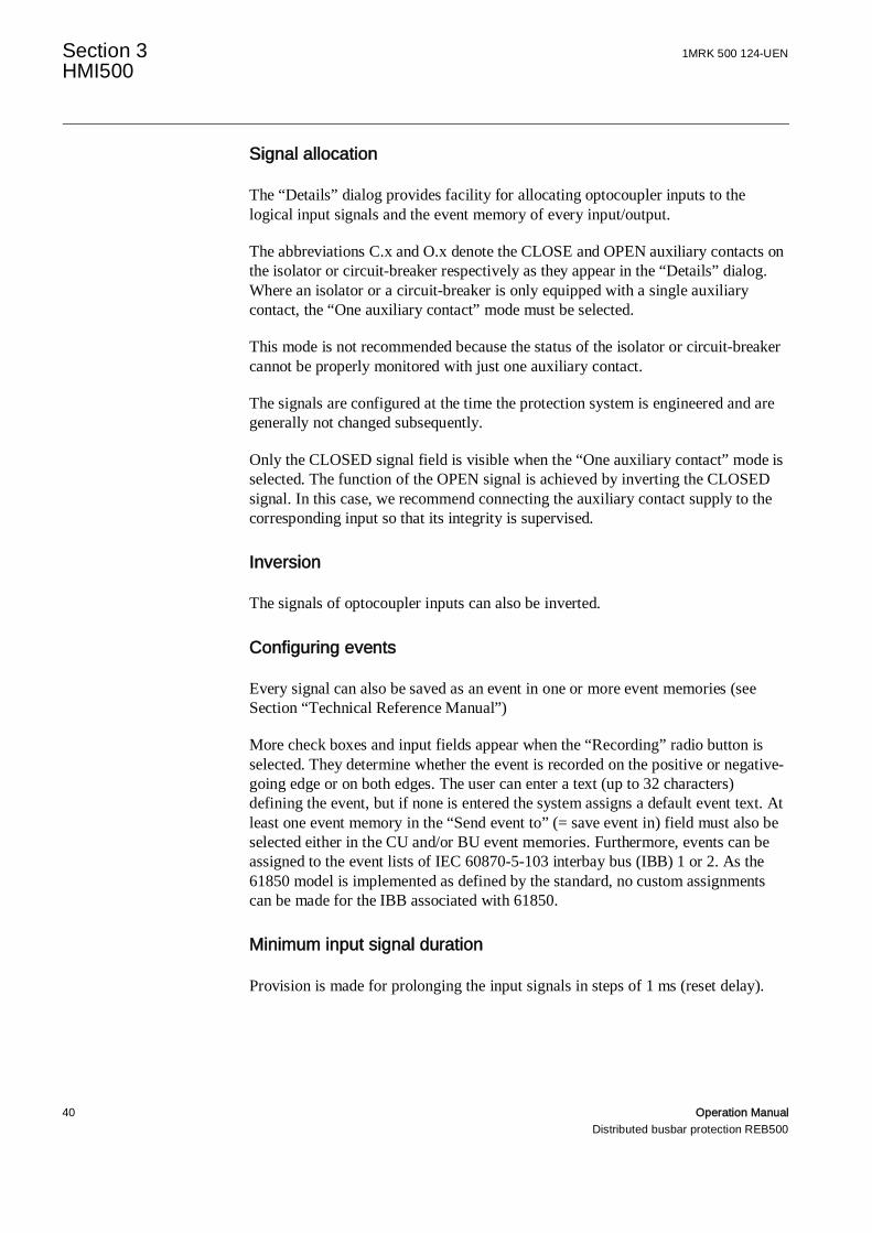
New Signal
Fig. 3.1 Configuration / Binary module - Inputs - New signal
The button “New signal” opens a dialog with a list for selecting and adding a newsignal.
Clicking on the arrow to the right of the “Signal type” field opens a list of availablesignals. The effective list depends on the functions ordered by the user. The list caninclude as a maximum the following groups:
• General signals• Busbar protection (BBP)• Breaker failure protection (BFP)• End fault protection (EFP)• Time-overcurrent protection (OCDT)• Disturbance recorder (DR)• CB pole discrepancy protection (PDF)• Voltage release (UV)
Clicking on the arrow button to the right of the signal name field opens a list of thesignals available according to the filter group and device selected.
Signals that can only be assigned once will disappear from the list as soon as theuser has assigned them.
The new signal can be configured as described above.
3.6.3.5 Outputs
The procedures for configuring binary inputs and outputs are almost identical, inparticular creating new signals and deleting existing ones. Therefore only thedifferences are dealt with in this section.
Section 3 1MRK 500 124-UENHMI500
42 Operation ManualDistributed busbar protection REB500
Most of the CU signals only occur once. There is an output signal“Trip BB zone” for each section of busbar (bus zone), therefore therespective zone must be given when selecting this signal.
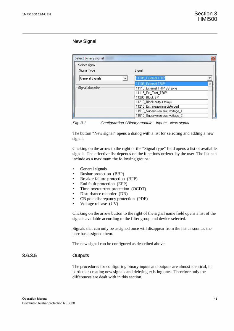
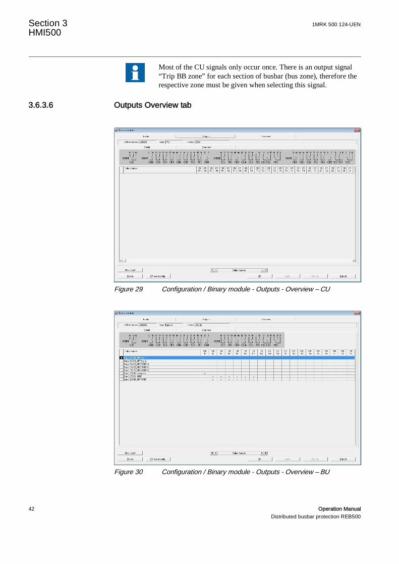
3.6.3.6 Outputs Overview tab
Figure 29 Configuration / Binary module - Outputs - Overview – CU
Figure 30 Configuration / Binary module - Outputs - Overview – BU
1MRK 500 124-UEN Section 3HMI500
Operation Manual 43Distributed busbar protection REB500
The overview of the BU outputs shows which signals are assigned to which outputrelays. An output relay can be controlled by several signals (e.g. relay CR02 by“TRIP” and “BFP TRIP”).
For reasons of safety, it is impossible to mix tripping commands and signals, i.e.tripping commands can only be combined with tripping commands and controlsignals with control signals.
Tripping commands:
• 21105_EXTERNAL TRIP• 21110_TRIP• 23105_BFP TRIP• 25105_OCDT TRIP• 27105_PDF TRIP
The remaining signals and all the CU signals are control signals.
It is recommended to configure tripping signals for operatingcircuit-breakers either to latch or to operate with a reset delay of atleast 100 ms.
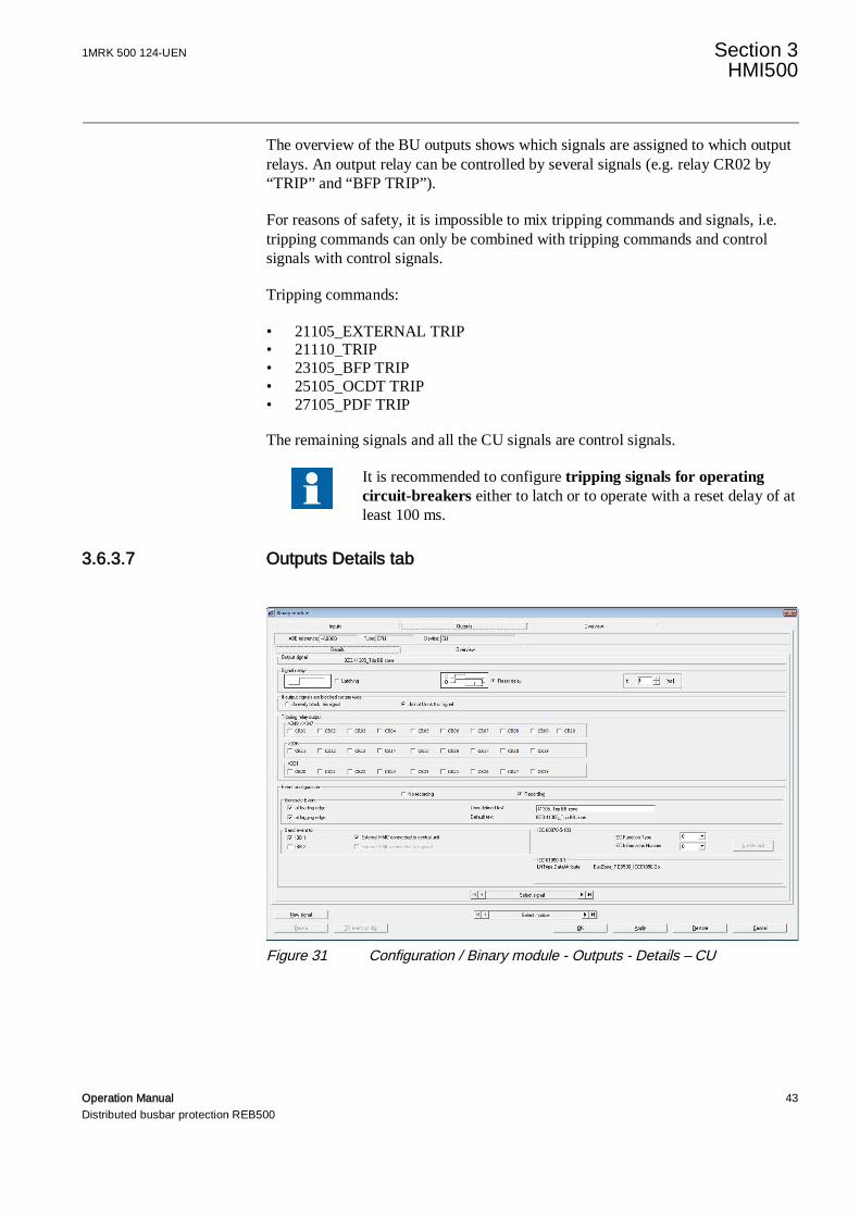
3.6.3.7 Outputs Details tab
Figure 31 Configuration / Binary module - Outputs - Details – CU
Section 3 1MRK 500 124-UENHMI500
44 Operation ManualDistributed busbar protection REB500
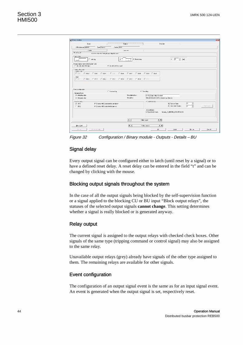
Figure 32 Configuration / Binary module - Outputs - Details – BU
Signal delay
Every output signal can be configured either to latch (until reset by a signal) or tohave a defined reset delay. A reset delay can be entered in the field “t” and can bechanged by clicking with the mouse.
Blocking output signals throughout the system
In the case of all the output signals being blocked by the self-supervision functionor a signal applied to the blocking CU or BU input “Block output relays”, thestatuses of the selected output signals cannot change. This setting determineswhether a signal is really blocked or is generated anyway.
Relay output
The current signal is assigned to the output relays with checked check boxes. Othersignals of the same type (tripping command or control signal) may also be assignedto the same relay.
Unavailable output relays (grey) already have signals of the other type assigned tothem. The remaining relays are available for other signals.
Event configuration
The configuration of an output signal event is the same as for an input signal event.An event is generated when the output signal is set, respectively reset.
1MRK 500 124-UEN Section 3HMI500
Operation Manual 45Distributed busbar protection REB500
Configuring output relay events
An event is generated when an output relay picks up or resets, i.e. this type of eventtakes any reset delay that has been set or blocking by another signal into account.
Select an output relay in the overview dialog first by clicking on its label above thesignal list (its column is then highlighted). Now open the event configurationdialog by clicking on the “CR event config.” button.
As in the case of the binary input signals in Section 3.6.3.2., the binary outputsignals are configured at the works.
3.6.4 GOOSE input support
GOOSE indications from protection IED’s (e.g. Line protection trip) can be used asinput signals for REB500 functions (e.g. Start breaker failure protection).
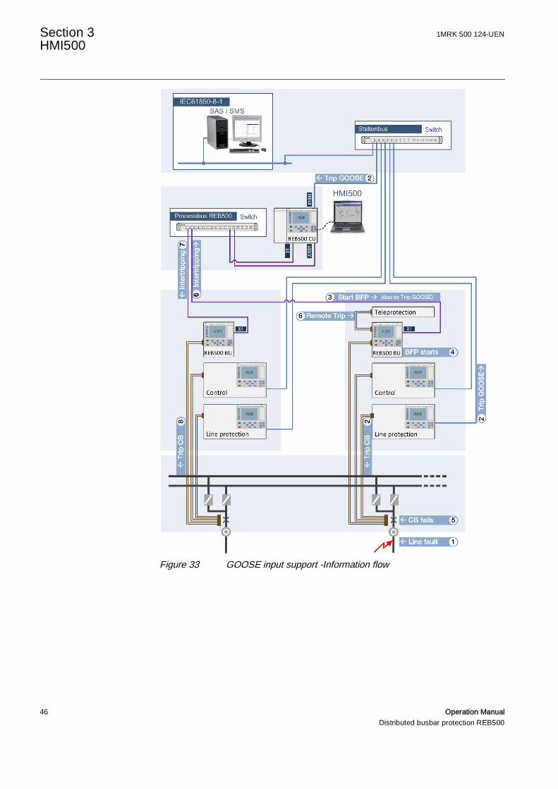
Figure 33 illustrates a line fault combined with a breaker failure condition, and theresulting information (trip signal) flow assumed that the REB500 starting input isbased on a GOOSE indication.
Section 3 1MRK 500 124-UENHMI500
46 Operation ManualDistributed busbar protection REB500
Figure 33 GOOSE input support -Information flow
1MRK 500 124-UEN Section 3HMI500
Operation Manual 47Distributed busbar protection REB500
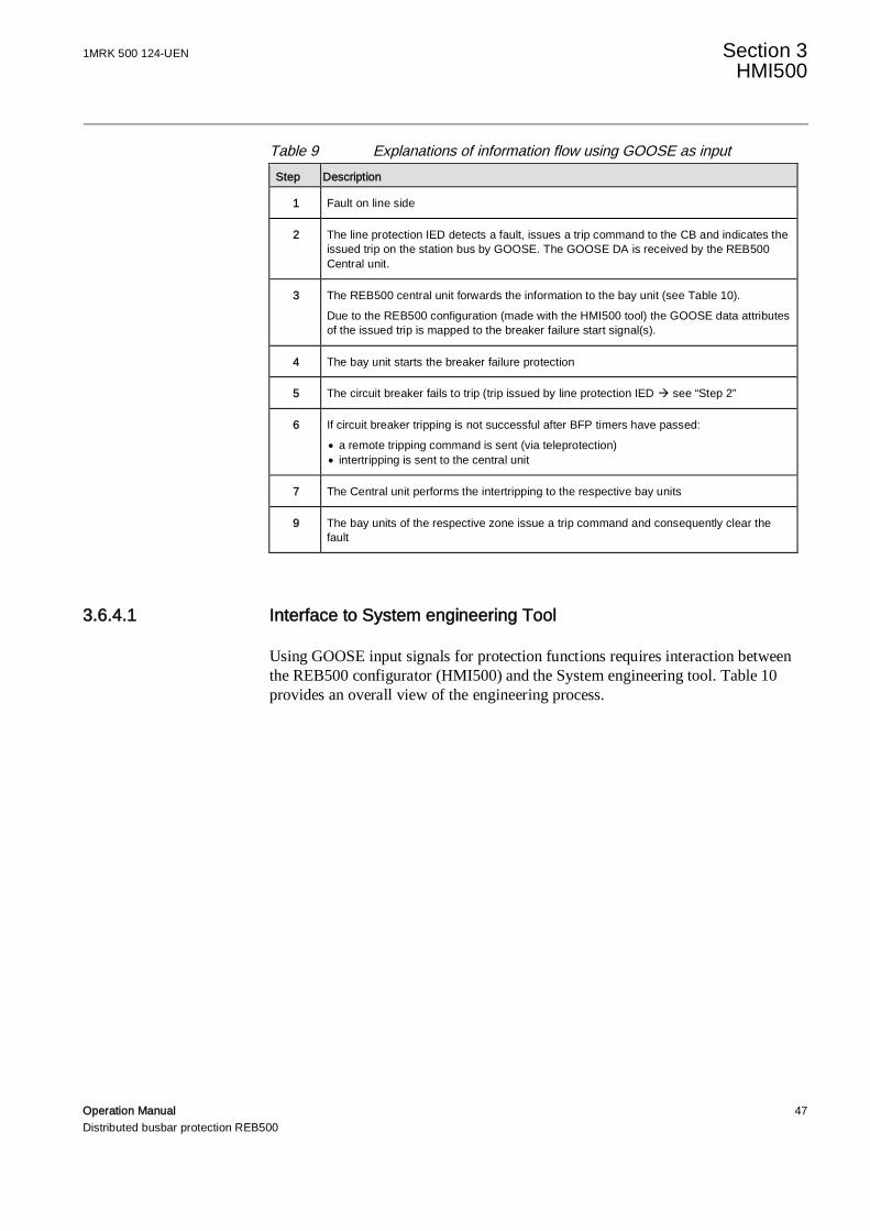
Table 9 Explanations of information flow using GOOSE as inputStep Description
1 Fault on line side
2 The line protection IED detects a fault, issues a trip command to the CB and indicates theissued trip on the station bus by GOOSE. The GOOSE DA is received by the REB500Central unit.
3 The REB500 central unit forwards the information to the bay unit (see Table 10).Due to the REB500 configuration (made with the HMI500 tool) the GOOSE data attributesof the issued trip is mapped to the breaker failure start signal(s).
4 The bay unit starts the breaker failure protection
5 The circuit breaker fails to trip (trip issued by line protection IED à see “Step 2”
6 If circuit breaker tripping is not successful after BFP timers have passed:· a remote tripping command is sent (via teleprotection)· intertripping is sent to the central unit
7 The Central unit performs the intertripping to the respective bay units
9 The bay units of the respective zone issue a trip command and consequently clear thefault
3.6.4.1 Interface to System engineering Tool
Using GOOSE input signals for protection functions requires interaction betweenthe REB500 configurator (HMI500) and the System engineering tool. Table 10provides an overall view of the engineering process.
Section 3 1MRK 500 124-UENHMI500
48 Operation ManualDistributed busbar protection REB500
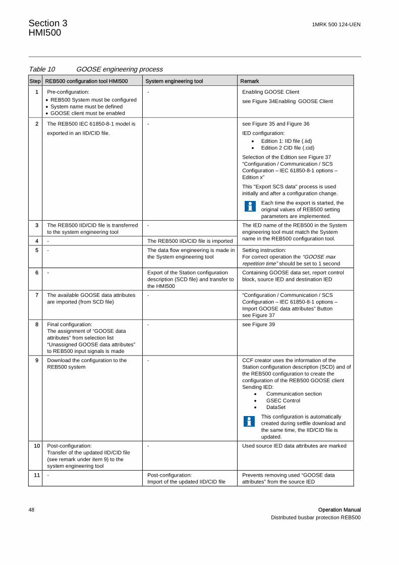
Table 10 GOOSE engineering processStep REB500 configuration tool HMI500 System engineering tool Remark
1 Pre-configuration:· REB500 System must be configured· System name must be defined· GOOSE client must be enabled
- Enabling GOOSE Clientsee Figure 34Enabling GOOSE Client
2 The REB500 IEC 61850-8-1 model isexported in an IID/CID file.
- see Figure 35 and Figure 36IED configuration:
· Edition 1: IID file (.iid)· Edition 2 CID file (.cid)
Selection of the Edition see Figure 37“Configuration / Communication / SCSConfiguration – IEC 61850-8-1 options –Edition x”This "Export SCS data" process is usedinitially and after a configuration change.
Each time the export is started, theoriginal values of REB500 settingparameters are implemented.
3 The REB500 IID/CID file is transferredto the system engineering tool
- The IED name of the REB500 in the Systemengineering tool must match the Systemname in the REB500 configuration tool.4 - The REB500 IID/CID file is imported
5 - The data flow engineering is made inthe System engineering tool
Setting instruction:For correct operation the “GOOSE maxrepetition time” should be set to 1 second
6 - Export of the Station configurationdescription (SCD file) and transfer tothe HMI500
Containing GOOSE data set, report controlblock, source IED and destination IED
7 The available GOOSE data attributesare imported (from SCD file)
- “Configuration / Communication / SCSConfiguration – IEC 61850-8-1 options –Import GOOSE data attributes” Buttonsee Figure 37
8 Final configuration:The assignment of “GOOSE dataattributes” from selection list“Unassigned GOOSE data attributes”to REB500 input signals is made
- see Figure 39
9 Download the configuration to theREB500 system
- CCF creator uses the information of theStation configuration description (SCD) and ofthe REB500 configuration to create theconfiguration of the REB500 GOOSE clientSending IED:
· Communication section· GSEC Control· DataSet
This configuration is automaticallycreated during setfile download andthe same time, the IID/CID file isupdated.
10 Post-configuration:Transfer of the updated IID/CID file(see remark under item 9) to thesystem engineering tool
- Used source IED data attributes are marked
11 - Post-configuration:Import of the updated IID/CID file
Prevents removing used “GOOSE dataattributes” from the source IED

1MRK 500 124-UEN Section 3HMI500
Operation Manual 49Distributed busbar protection REB500
3.6.4.2 Enabling GOOSE Client
This section describes the pre-configuration of the GOOSE Client.
Figure 34 Configuration / Binary module - Inputs – Details– Contact mode
The GOOSE Client is enabled if at least one of the REB500 input signals has beenconfigured as “GOOSE input”. The Radio Button “GOOSE input” is only availablefor specific REB500 signals. The “Assign” Button is enabled after the Stationconfiguration file (SCD) has been imported.
Section 3 1MRK 500 124-UENHMI500
50 Operation ManualDistributed busbar protection REB500
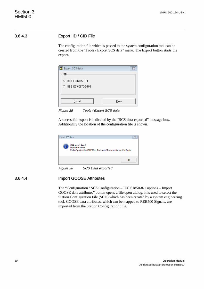
3.6.4.3 Export IID / CID File
The configuration file which is passed to the system configuration tool can becreated from the “Tools / Export SCS data” menu. The Export button starts theexport.
Figure 35 Tools / Export SCS data
A successful export is indicated by the “SCS data exported” message box.Additionally the location of the configuration file is shown.
Figure 36 SCS Data exported
3.6.4.4 Import GOOSE Attributes
The “Configuration / SCS Configuration – IEC 61850-8-1 options – ImportGOOSE data attributes” button opens a file open dialog. It is used to select theStation Configuration File (SCD) which has been created by a system engineeringtool. GOOSE data attributes, which can be mapped to REB500 Signals, areimported from the Station Configuration File.
1MRK 500 124-UEN Section 3HMI500
Operation Manual 51Distributed busbar protection REB500
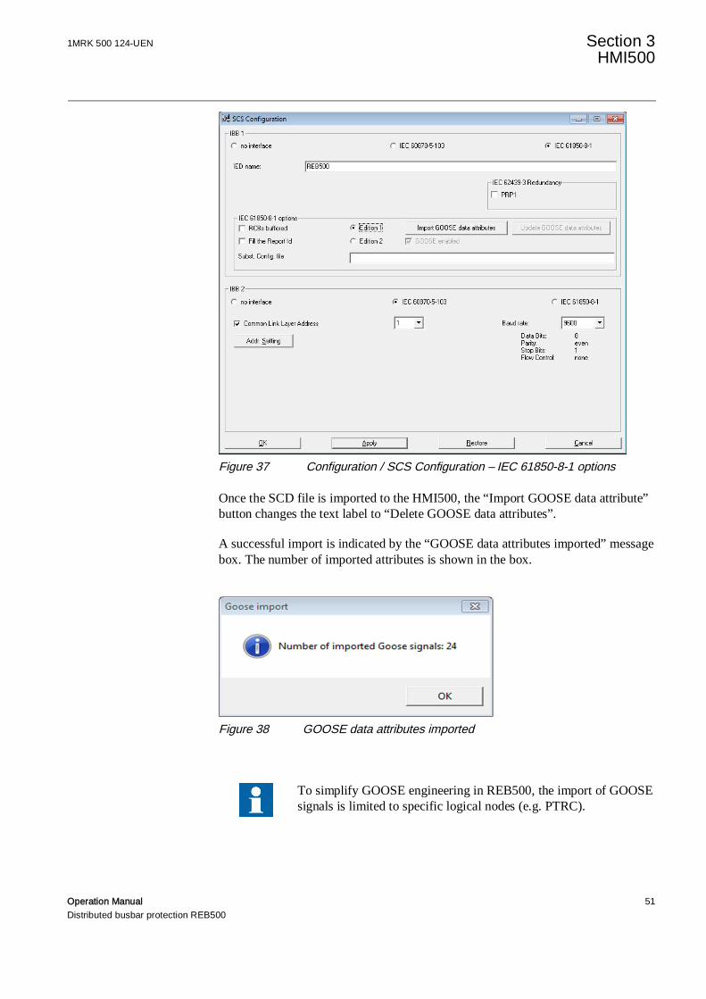
Figure 37 Configuration / SCS Configuration – IEC 61850-8-1 options
Once the SCD file is imported to the HMI500, the “Import GOOSE data attribute”button changes the text label to “Delete GOOSE data attributes”.
A successful import is indicated by the “GOOSE data attributes imported” messagebox. The number of imported attributes is shown in the box.
Figure 38 GOOSE data attributes imported
To simplify GOOSE engineering in REB500, the import of GOOSEsignals is limited to specific logical nodes (e.g. PTRC).
Section 3 1MRK 500 124-UENHMI500
52 Operation ManualDistributed busbar protection REB500
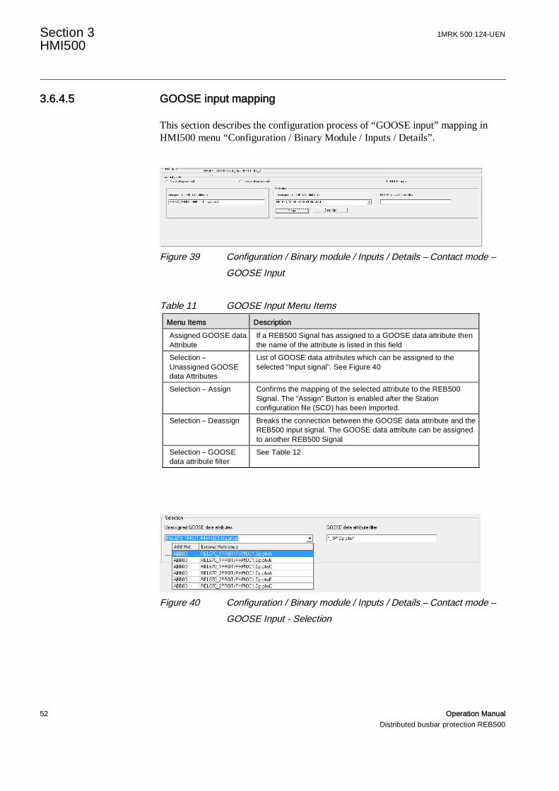
3.6.4.5 GOOSE input mapping
This section describes the configuration process of “GOOSE input” mapping inHMI500 menu “Configuration / Binary Module / Inputs / Details”.
Figure 39 Configuration / Binary module / Inputs / Details – Contact mode –GOOSE Input
Table 11 GOOSE Input Menu ItemsMenu Items DescriptionAssigned GOOSE dataAttribute
If a REB500 Signal has assigned to a GOOSE data attribute thenthe name of the attribute is listed in this field
Selection –Unassigned GOOSEdata Attributes
List of GOOSE data attributes which can be assigned to theselected “Input signal”. See Figure 40
Selection – Assign Confirms the mapping of the selected attribute to the REB500Signal. The “Assign” Button is enabled after the Stationconfiguration file (SCD) has been imported.
Selection – Deassign Breaks the connection between the GOOSE data attribute and theREB500 input signal. The GOOSE data attribute can be assignedto another REB500 Signal
Selection – GOOSEdata attribute filter
See Table 12
Figure 40 Configuration / Binary module / Inputs / Details – Contact mode –GOOSE Input - Selection

1MRK 500 124-UEN Section 3HMI500
Operation Manual 53Distributed busbar protection REB500
Table 12 Selection ElementsMenu Items DescriptionUnassigned GOOSEAttribute – ABB Ref
REB500 Internal designation for the bay or central unit.
Unassigned GOOSEAttribute – ExternalReference
Full name of the GOOSE data attribute. The full name comprises:IED name, Logical Device Instance, Prefix, Logical Node Class, logicalNode instance, Data Object name and Data attribute Name
Selection – GOOSEattribute filter
Regular expression which limits the number of GOOSE data attribute inthe list of Unassigned GOOSE attributes:? = any character* = none, one or any number of charactersThe comparison is case insensitive.examples: “*_1*Op*”, “*_?P*Op*”, “*_?P*Op.phs*”
3.6.4.6 Requirements to GOOSE input signals
The REB500 GOOSE input signals have to comply with therequirements for the corresponding “standard” input signal. Non-conformance may lead into unwanted operation of the protectionsystem.
Example:
The breaker failure protection remote trip (timer t1) and the intertripping to all bayunits of a bus zone (timer t2) implies that the fault still persists at the end of therespective timer. Consequently, the GOOSE input signal (trip from line protection)mapped to the BFP start signal must therefore be reliably present during both timesteps.
3.6.4.7 Disabling GOOSE client
The GOOSE Client is disabled if none of the REB500 input signals have beenconfigured as “GOOSE input” and GOOSE data attributes have been deleted in the“Configuration / SCS Configuration – IEC 61850-8-1 options”.

Section 3 1MRK 500 124-UENHMI500
54 Operation ManualDistributed busbar protection REB500
3.6.5 Event text configuration
In this window all the event signals configured for REB500 are displayed. For eachevent signal a user specific text can be defined (maximal 32 characters). The usercan sort the list as per ABB reference or the standard text.
Figure 41 Event text configuration
3.6.6 HMI LEDs
This dialog contains the list of bay units and the central unit (“LMI LEDconfiguration”). The unit specific configuration dialog (“LED statuses on the localHMI”) is opened by selecting the desired bay unit or central unit with the leftmouse button and then clicking on “Continue” or directly by simply doubleclicking on the unit line.

1MRK 500 124-UEN Section 3HMI500
Operation Manual 55Distributed busbar protection REB500
Figure 42 LMI LED configuration (List of units/ Print dialog)
Figure 43 Status LED on the LMI (LED Configuration dialog)
Under the “Status LED on LMI” dialogue the number of the LED on the local HMIis given in the ID column.
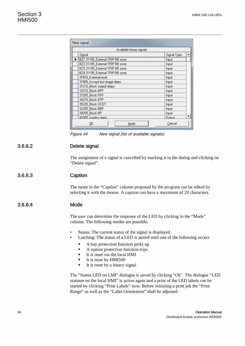
3.6.6.1 New signal
A LED is assigned to a signal by marking it in the dialog and clicking on “Newsignal” or alternatively by double clicking on the LED line. A list of possiblesignals is then presented to enable one to be chosen.
Section 3 1MRK 500 124-UENHMI500
56 Operation ManualDistributed busbar protection REB500
Figure 44 New signal (list of available signals)
3.6.6.2 Delete signal
The assignment of a signal is cancelled by marking it in the dialog and clicking on“Delete signal”.
3.6.6.3 Caption
The name in the “Caption” column proposed by the program can be edited byselecting it with the mouse. A caption can have a maximum of 20 characters.
3.6.6.4 Mode
The user can determine the response of the LED by clicking in the “Mode”column. The following modes are possible:
• Status: The current status of the signal is displayed.• Latching: The status of a LED is stored until one of the following occurs
§ A bay protection function picks up§ A station protection function trips§ It is reset via the local HMI§ It is reset by HMI500§ It is reset by a binary signal
The “Status LED on LMI” dialogue is saved by clicking “Ok”. The dialogue “LEDstatuses on the local HMI” is active again and a print of the LED labels can bestarted by clicking “Print Labels” now. Before initiating a print job the “PrintRange” as well as the “Label Orientation” shall be adjusted.
1MRK 500 124-UEN Section 3HMI500
Operation Manual 57Distributed busbar protection REB500
3.6.7 Disturbance recorder
3.6.7.1 Analog inputs
Bay Units
The currents measured by the four analog inputs are always recorded. The fivevoltage inputs may only be recorded providing they have been licensed andengineered (optional).
The recording time is doubled if the voltage channels are not activated.
Central Unit
The differential and restraint currents for each buszone are always recorded.
The dialog has three tabs:
Overview
The overview shows all devices and their basic disturbance recorderconfigurations. A device is selected by clicking on it with the mouse.
The column “ABB ref.” indicates an internal designation for the devices. Thereference “=ABB00” is always assigned to the central unit. The references“=ABB01-xx” are assigned to the bay units.
License status
This dialog lists all the licensed devices and the duration of recording (seeFigure 49).
Configuration
The configuration dialog shows a device together with its recording mode andsignals.
3.6.7.2 Recording
Bay Units
The following disturbance recorder settings can be made (see Figure 45).Sampling frequency (50 Hz/60 Hz): 1000/1200 Hz, 2000/2400 Hz or4000/4800 Hz. The maximum recording time is automatically adjusted to suit.

Section 3 1MRK 500 124-UENHMI500
58 Operation ManualDistributed busbar protection REB500
• Number of records “n”: The maximum recording time available is divided bythis setting into “n" equal time periods. For example, assuming 3 records haveto be made for a sampling frequency of 2000Hz, then 13.33 seconds each canbe recorded.
• Acquisition time: This setting determines how much time before the triggeringpoint is included in the record. The recording time must be at least 0.2 s torecord the pre-fault and 0.3s for the post-fault history.
Central Unit
The following disturbance recorder settings can be made (see Figure 46).
• Number of records “n”: The maximum recording time available is divided bythis setting into “n" equal time periods. For example, assuming 3 records haveto be made, then 6.67 seconds each can be recorded.
• Acquisition time: This setting determines how much time before the triggeringpoint is included in the record. The recording time must be at least 0.2 s torecord the pre-fault and 0.3s for the post-fault history.
3.6.7.3 Signals
Bay Units
All binary signals (input, output or internal signal) can be recorded. For thispurpose, they must be configured for recording and identified by their signal labels.
Up to 32 binary signals per bay can be selected for recording. Of these, up to 12can be configured to trigger the start of recording. Triggering can take place on thelagging or leading edge of a signal. If “both edges” is selected, both lagging andleading edges are active (see Figure 47).
Once recording has been started, the complete recording period that has been set isrecorded.
In addition to the normal bay unit binary signals, there are up to ten generalpurpose input signals that can be configured for recording and for triggering thedisturbance recorder (“16705… 16750_Start DR_x”).
Central Unit
Some binary output signals can be recorded (see Table 13). For this purpose, theymust be configured for recording and identified by their signal labels.
Up to 64 signals can be selected for recording. Triggering can take place on thelagging or leading edge of a signal. If “both edges” is selected, both lagging andleading edges are active (see Figure 47).
1MRK 500 124-UEN Section 3HMI500
Operation Manual 59Distributed busbar protection REB500
Once recording has been started, the complete recording period that has been set isrecorded.
Unlike the bay units, there are no dedicated general purpose input signals forrecording and triggering.
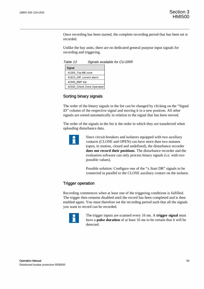
Table 13 Signals available for CU-DRRSignal41305_Trip BB zone41815_Diff. current alarm42305_BBP trip42330_Check Zone Operated
Sorting binary signals
The order of the binary signals in the list can be changed by clicking on the “SignaliD” column of the respective signal and moving it to a new position. All othersignals are sorted automatically in relation to the signal that has been moved.
The order of the signals in the list is the order in which they are transferred whenuploading disturbance data.
Since circuit-breakers and isolators equipped with two auxiliarycontacts (CLOSE and OPEN) can have more than two statuses(open, in motion, closed and undefined), the disturbance recorderdoes not record their positions. The disturbance recorder and theevaluation software can only process binary signals (i.e. with twopossible values).
Possible solution: Configure one of the “x.Start DR” signals to beconnected in parallel to the CLOSE auxiliary contact on the isolator.
Trigger operation
Recording commences when at least one of the triggering conditions is fulfilled.The trigger then remains disabled until the record has been completed and is thenenabled again. You must therefore set the recording period such that all the signalsyou want to record can be recorded.
The trigger inputs are scanned every 16 ms. A trigger signal musthave a pulse duration of at least 16 ms to be certain that it will bedetected.

Section 3 1MRK 500 124-UENHMI500
60 Operation ManualDistributed busbar protection REB500
Figure 45 Disturbance recorder – Configuration (Bay Unit)
Figure 46 Disturbance recorder – Configuration (Central Unit)

1MRK 500 124-UEN Section 3HMI500
Operation Manual 61Distributed busbar protection REB500
Figure 47 Disturbance recorder - Configuration – Signals
Figure 48 Disturbance recorder – Overview

Section 3 1MRK 500 124-UENHMI500
62 Operation ManualDistributed busbar protection REB500
Figure 49 Disturbance recorder - License status
3.7 Settings menu
In general, the settings are described in the Technical Manual. Detailedexplanations and examples can be found in the Application Manual. Table 14provides pointers to the respective sections in the Technical Manual and in theApplication Manual.
Not all settings are available for all systems. Some settings depend on the scope ofsupply (marked ○ in column Av) while others are always available (●).
Table 14 Settings menu itemsSetting menu item Av Technical Manual section Application Manual sectionBreaker failure protection ○ 5.1 9Time overcurrent protection ○ 5.2 -End fault protection ○ 5.3 -CB pole discrepancy ○ 5.4 -Overcurrent release ○ 6.2.1 -Voltage release ○ 6.1 -Circuit-breakers ● 3.1 -Isolators ● 3.2 -Current transformers ● 3.3 -Voltage transformers ○ 3.4 -

1MRK 500 124-UEN Section 3HMI500
Operation Manual 63Distributed busbar protection REB500
Busbar protection ● 4 7Release logic / matrix ● 6.2.2 -System response ● 3.5 -Activate/deactivate device ● see Commissioning Manual -CB inspection ● see Commissioning Manual -Event memory ● 3.6 -Time ● 3.7 -
3.8 Testing menu
3.8.1 Test mode
Switching to the test mode while the protection is in operationshould only be undertaken by especially trained personnel.Incorrect manipulations can cause false tripping, for example, byinadvertently operating a tripping relay, simulating an incorrectisolator or circuit-breaker status or activating a tripping input (e.g.External TRIP).
The test generator is activated by opening the “Testing” menu, selecting “Testmode”. A tick appears next to the menu item, “Test mode” is added to the statusline at the bottom of the screen and the “Test mode” dialog opens.
The test generator is used in conjunction with the “Status of binary inputs/outputs”dialog (has to be opened by the operator), (see Section 3.5.4).
When the test generator is active, the statuses of the tripping commands cannotchange.
Section 3 1MRK 500 124-UENHMI500
64 Operation ManualDistributed busbar protection REB500
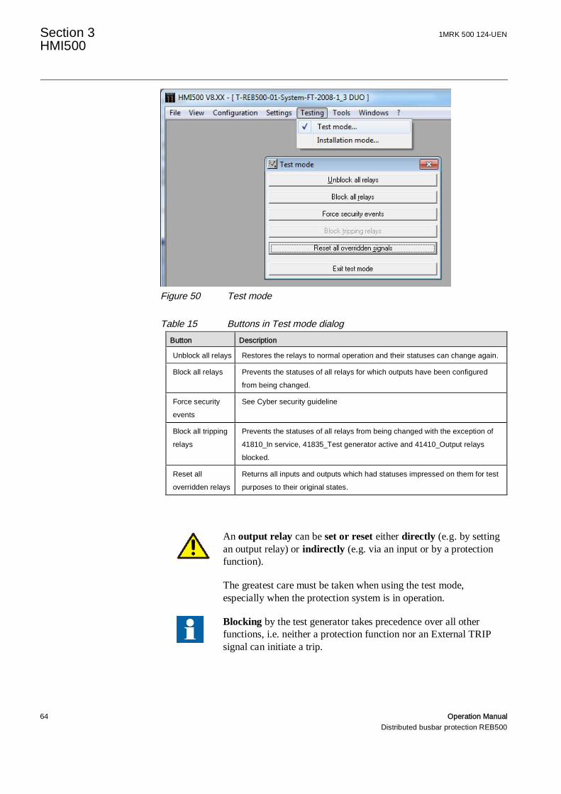
Figure 50 Test mode
Table 15 Buttons in Test mode dialogButton Description
Unblock all relays Restores the relays to normal operation and their statuses can change again.
Block all relays Prevents the statuses of all relays for which outputs have been configuredfrom being changed.
Force securityevents
See Cyber security guideline
Block all trippingrelays
Prevents the statuses of all relays from being changed with the exception of41810_In service, 41835_Test generator active and 41410_Output relaysblocked.
Reset alloverridden relays
Returns all inputs and outputs which had statuses impressed on them for testpurposes to their original states.
An output relay can be set or reset either directly (e.g. by settingan output relay) or indirectly (e.g. via an input or by a protectionfunction).
The greatest care must be taken when using the test mode,especially when the protection system is in operation.
Blocking by the test generator takes precedence over all otherfunctions, i.e. neither a protection function nor an External TRIPsignal can initiate a trip.
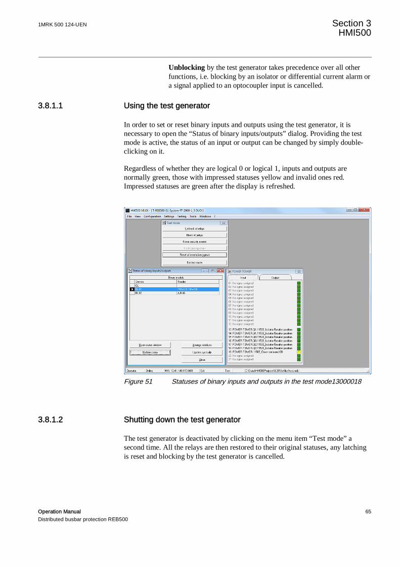
1MRK 500 124-UEN Section 3HMI500
Operation Manual 65Distributed busbar protection REB500
Unblocking by the test generator takes precedence over all otherfunctions, i.e. blocking by an isolator or differential current alarm ora signal applied to an optocoupler input is cancelled.
3.8.1.1 Using the test generator
In order to set or reset binary inputs and outputs using the test generator, it isnecessary to open the “Status of binary inputs/outputs” dialog. Providing the testmode is active, the status of an input or output can be changed by simply double-clicking on it.
Regardless of whether they are logical 0 or logical 1, inputs and outputs arenormally green, those with impressed statuses yellow and invalid ones red.Impressed statuses are green after the display is refreshed.
Figure 51 Statuses of binary inputs and outputs in the test mode13000018
3.8.1.2 Shutting down the test generator
The test generator is deactivated by clicking on the menu item “Test mode” asecond time. All the relays are then restored to their original statuses, any latchingis reset and blocking by the test generator is cancelled.

Section 3 1MRK 500 124-UENHMI500
66 Operation ManualDistributed busbar protection REB500
3.8.2 Installation mode
This mode is activated by opening the “Testing” menu, selecting “Installationmode”.
A tick appears next to the menu item, “Installation mode” is displayed on the statusline at the bottom of the screen and the “Installation mode” dialog opens.
Click on “Installation mode” in the “Testing” menu to reset the installation mode.The tick in the menu item is reset.
Figure 52 Installation mode menu
Table 16 Buttons in Installation mode menu Button Description
Delete data base in theprotection system
All the data in the protection system are deleted, i.e. the projectdatabase (MDB file) in the protection system is deleted.
Restart the protection system Reinitializes the protection (CU and all BU’s)
Debug mode In the debug mode, the protection system generates additionalinternal program events. As a rule, the debug mode is only used by
the ABB engineering department for test purposes.
Read Traceability information The system info, the order codes of the central unit and the bay units(the decoding of the order code is shown in chapter “Ordering forcustomized IED” in the REB500 Product Guide), the hardware data(type, serial number, revision index, date of manufacture etc.) andthe software data (version) are uploaded from the protectionequipment and added to the HMI500 report section (see Menu item“Tools/ Reports/ Traceability data”)
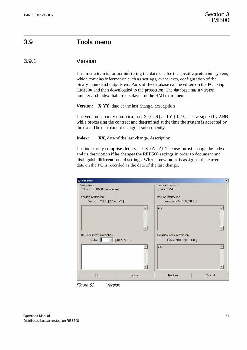
1MRK 500 124-UEN Section 3HMI500
Operation Manual 67Distributed busbar protection REB500
3.9 Tools menu
3.9.1 Version
This menu item is for administering the database for the specific protection system,which contains information such as settings, event texts, configuration of thebinary inputs and outputs etc. Parts of the database can be edited on the PC usingHMI500 and then downloaded to the protection. The database has a versionnumber and index that are displayed in the HMI main menu.
Version: X.YY, date of the last change, description
The version is purely numerical, i.e. X {0...9} and Y {0...9}. It is assigned by ABBwhile processing the contract and determined at the time the system is accepted bythe user. The user cannot change it subsequently.
Index: XX, date of the last change, description
The index only comprises letters, i.e. X {A...Z}. The user must change the indexand its description if he changes the REB500 settings in order to document anddistinguish different sets of settings. When a new index is assigned, the currentdate on the PC is recorded as the date of the last change.
Figure 53 Version

Section 3 1MRK 500 124-UENHMI500
68 Operation ManualDistributed busbar protection REB500
3.9.2 File verification
Starts the file verification procedure, that checks data consistency within severaltables of the project file. The result is displayed in a separate window.
3.9.3 Reports
Figure 54 Reports
The “Reports” dialog is opened by selecting “Reports” in the “Tools” menu. Itcontains a list of the various kinds of reports.
Either a desired report can be printed on its own or all the reports can be printed byactivating the “Print all reports” check box.
The difference between the options in the “Printing quality” field is that the dataare presented in tabular form if the “Normal” radio button is active.
Unless a printer is actually installed on the PC, the “Reports” menu item is greyand inactive. A printer does not, however, have to be connected.
3.9.4 Export SCS data
This menu item exports any communication data contained in the database. Themenu is only active if under menu “Configuration \ Communication” a SCSinterface is configured (see 3.6.1).

1MRK 500 124-UEN Section 3HMI500
Operation Manual 69Distributed busbar protection REB500
In the case of the optional IEC 61850-8-1 and IEC 60870-5-103 communicationprotocols, the “Export” button creates files that can be used to configure thecommunication interface at the remote end.
3.9.5 Settings
3.9.5.1 HMI500 settings
Some of the operator program functions can be customized:
Figure 55 HMI500 settings
3.9.5.2 Communication
Communication can be established with a REB500 system either via HMI frontconnector or via the station bus.
Settings are provided for the TCP/IP address of the REB system to whichcommunication is being established.
It is possible to change between the communication modes On-line, Off-line andSimulation. Selecting “On-line” causes HMI500 to check whether communicationwith REB500 system can be established.
The checkbox “Enable security menu” and its influence to the sub-menus “Tools /Security option” and “Tools / Security account management” is described under“Security deployment guideline.
3.9.5.3 Parameters for reading and exporting event data
Settings are provided for the period for cyclically reading events and the separatorfor an ASCII file when exporting events.
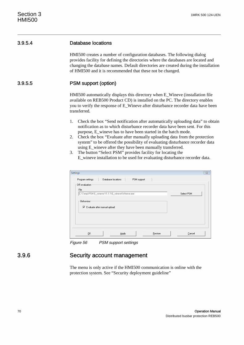
Section 3 1MRK 500 124-UENHMI500
70 Operation ManualDistributed busbar protection REB500
3.9.5.4 Database locations
HMI500 creates a number of configuration databases. The following dialogprovides facility for defining the directories where the databases are located andchanging the database names. Default directories are created during the installationof HMI500 and it is recommended that these not be changed.
3.9.5.5 PSM support (option)
HMI500 automatically displays this directory when E_Wineve (installation fileavailable on REB500 Product CD) is installed on the PC. The directory enablesyou to verify the response of E_Wineve after disturbance recorder data have beentransferred.
1. Check the box “Send notification after automatically uploading data” to obtainnotification as to which disturbance recorder data have been sent. For thispurpose, E_wineve has to have been started in the batch mode.
2. Check the box “Evaluate after manually uploading data from the protectionsystem” to be offered the possibility of evaluating disturbance recorder datausing E_wineve after they have been manually transferred.
3. The button “Select PSM” provides facility for locating theE_wineve installation to be used for evaluating disturbance recorder data.
Figure 56 PSM support settings
3.9.6 Security account management
The menu is only active if the HMI500 communication is online with theprotection system. See “Security deployment guideline”

1MRK 500 124-UEN Section 3HMI500
Operation Manual 71Distributed busbar protection REB500
3.9.7 Change password
See “Security deployment guideline”
3.9.8 Security options
See “Security deployment guideline”
3.9.9 Security log servers
See “Security deployment guideline”
3.9.10 Close all sessions
This menu command closes all open sessions on the target device.
3.9.11 Set system time
The system clock in the protection system is equipped with a standby battery andruns independently with an accuracy of 50 ppm (4.3 s per day) if not synchronizedperiodically by an external reference. In this case, this menu is used for setting thedate and time of the protection system. Initially, the date and time displayed in thismenu item are those effective on the PC. The settings in the fields can beincremented or decremented by clicking on the appropriate arrow to the right of thevalue. Click on “Set time” to set the new date and time on the protection system.
Figure 57 Setting the system time

Section 4 1MRK 500 124-UENLocal HMI
72 Operation ManualDistributed busbar protection REB500
Section 4 Local HMI
4.1 Introduction
REB500 includes continuous comprehensive self-supervision and diagnosis of thesoftware and hardware components. By setting up a proper signaling scheme whilecommissioning the system, most failures are signaled externally (see Section 3.6.3“Binary input/output signals”). They can include internal REB500 as well asexternal failures in primary and secondary systems that influence the response ofthe protection. Other failures that are not detected (e.g. interrupted tripping circuit)are located and cleared while carrying out periodic inspection and maintenance(see “Commissioning manual”. Checks and measurements while the system is innormal operation (no active alarms) are therefore unnecessary.
Normal operation without any faults is also indicated by the factthat only the green protection LED is lit and the alarm page LED isnot lit on the local HMI.
An alarm (external or on the local HMI) can concern a failure in the REB500system (e.g. hardware failure) or in the associated primary plant (e.g. incorrectisolator status signal).
Should the system generate an alarm, inform the trainedmaintenance personnel responsible.
4.2 Safety instructions
Checks and maintenance on the REB500 system may only becarried out by properly trained personnel.
Only properly trained and authorized personnel should be inpossession of the HMI500 password.
1MRK 500 124-UEN Section 4Local HMI
Operation Manual 73Distributed busbar protection REB500
4.3 Operation
4.3.1 Introduction
Operation in the case of the busbar protection system is confined to supervising theproper function of the system and assessing the system data.
There are different ways of viewing operating, disturbance and tripping data:
• local HMI• PC running HMI500• remote HMI• station automation system (SCS)
(see Section 2 “System Overview”)
4.3.2 Viewing data on the local HMI
The local HMI provides a quick overview of the status of the protection (normaloperation, alarms and trips) without having to connect a PC.
It is fitted in every central unit and as an option in the bay units. On the front, it hasa 320 by 240 pixel display, three protection LEDs, 19 pushbuttons and 15signalization/alarm LEDs. The local HMI enable the equipment to be operated andcontrolled simply and conveniently where it is installed. An interface is alsoprovided for connecting a PC via RS45
Whether on the central unit or a bay unit, the local HMI enables the following to beviewed:
• current and voltage measurements• statuses of inputs and outputs• alarms (generated by the respective bay unit)• system (or respective bay unit) settings• settings of all the specific bay unit protection functions
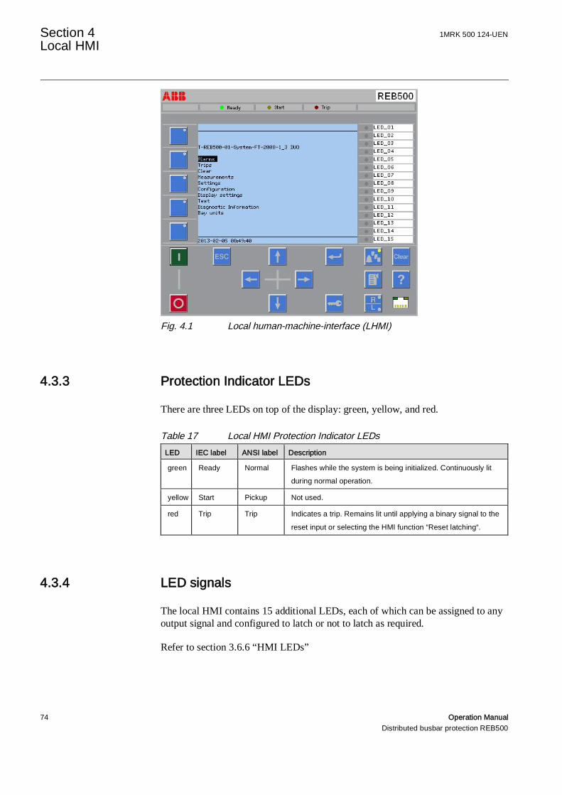
Section 4 1MRK 500 124-UENLocal HMI
74 Operation ManualDistributed busbar protection REB500
Fig. 4.1 Local human-machine-interface (LHMI)
4.3.3 Protection Indicator LEDs
There are three LEDs on top of the display: green, yellow, and red.
Table 17 Local HMI Protection Indicator LEDsLED IEC label ANSI label Description
green Ready Normal Flashes while the system is being initialized. Continuously litduring normal operation.
yellow Start Pickup Not used.
red Trip Trip Indicates a trip. Remains lit until applying a binary signal to the
reset input or selecting the HMI function “Reset latching“.
4.3.4 LED signals
The local HMI contains 15 additional LEDs, each of which can be assigned to anyoutput signal and configured to latch or not to latch as required.
Refer to section 3.6.6 “HMI LEDs”

1MRK 500 124-UEN Section 4Local HMI
Operation Manual 75Distributed busbar protection REB500
4.3.5 LCD backlight
If none of the buttons are operated for a time corresponding to the backlighttimeout, the display backlight switches off and the main menu is displayed with thecursor at the topmost menu position. It switches on again automatically as soon asa button is pressed.
The currently configured backlight supervision timeout can be viewed andmodified in menu “Display Settings”.
4.3.6 Buttons
Table 18 lists the nine supported buttons. They are used primarily to navigatethrough the menu structure. Any of them switches the display backlight on again ifit was switched off.
Table 18 Local HMI – Used ButtonsButton Name Purpose
Up Move up and down in menu tree and in pages.Move selection in dialogs and alarm panel.Scroll active digits, characters, or enumerators of a parameter when enteringa new setting value.
Down
Left Move left and right in menu tree (change menu tree level) and in pages.Change the active digit or character in parameter when entering a new value.
Right
Enter Enter the setting mode of a parameter.Confirm a new value of a setting parameter.Confirm selection in dialogs.
Escape Cancel currently ongoing operation.
Menu Navigate directly to the main menu.
Clear Navigate to the view for clearing or acknowledging alarms, trips and LEDs.
Multipage At first push it navigates to the alarm page. At second push it navigates tothe alarm LED panel, which displays the text associated with the
corresponding signalization LED on the right panel side.For setting the LED signals see Section 3.6.6
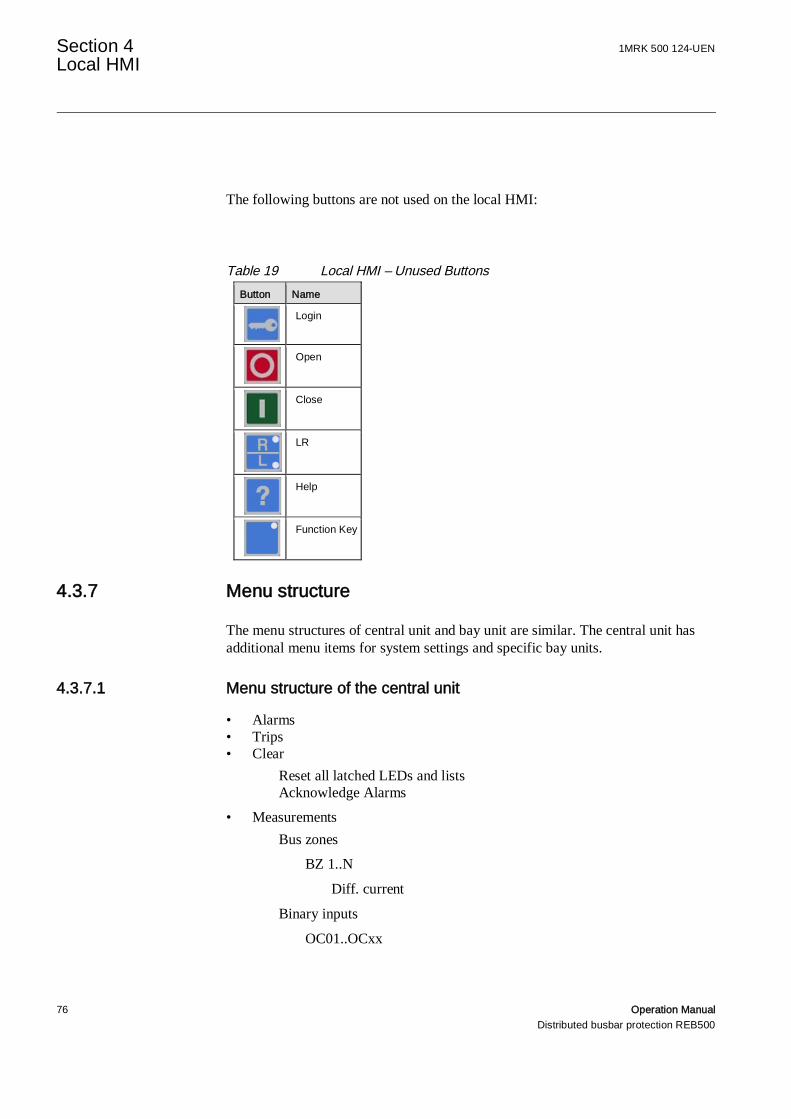
Section 4 1MRK 500 124-UENLocal HMI
76 Operation ManualDistributed busbar protection REB500
The following buttons are not used on the local HMI:
Table 19 Local HMI – Unused ButtonsButton Name
Login
Open
Close
LR
Help
Function Key
4.3.7 Menu structure
The menu structures of central unit and bay unit are similar. The central unit hasadditional menu items for system settings and specific bay units.
4.3.7.1 Menu structure of the central unit
• Alarms• Trips• Clear
Reset all latched LEDs and listsAcknowledge Alarms
• MeasurementsBus zones
BZ 1..N
Diff. current
Binary inputs
OC01..OCxx

1MRK 500 124-UEN Section 4Local HMI
Operation Manual 77Distributed busbar protection REB500
Binary outputs
CR01..CRxx
• SettingsSystem responseBusbar protection
• ConfigurationLAN IP settings
Process busHMIIEC61850
System Information
Station NameSystem frequencyDB VersionIndex to last DB changeDate of last DB change
LED Text
LED Text 1..15
• Display settingsLanguageLHMI
Display TimeoutContrast LevelKey Parameters
• TestLED Test
• Diagnostic InformationProduct Identifiers
IEDProdTypeFirmware VersionSerial NumberProduction DateOrdering NumberOrder Code
CPU LoadModule CheckSystem Logger
• Bay unitsBay unit 1..N
Measurements
Section 4 1MRK 500 124-UENLocal HMI
78 Operation ManualDistributed busbar protection REB500
CurrentsVoltagesBinary inputsOC01..OCxx
Binary outputs
CR01..CRxx
Switchgear objectsSettings
Busbar protectionBreaker failure protectionOvercurrent protectionEnd fault protectionPole discrepancy prot.
4.3.7.2 Menu structure of the bay unit
• Alarms• Trips• Clear
Reset all latched LEDs and listsAcknowledge AlarmsReset blocking signals
• MeasurementsCurrentsVoltagesBinary inputs
OC01..OCxx
Binary outputs
CR01..CRxx
Switchgear objects
• SettingsBusbar protectionBreaker failure protectionOvercurrent protectionEnd fault protectionPole discrepancy prot.
• ConfigurationLAN IP settings
Process busHMI
System Information
1MRK 500 124-UEN Section 4Local HMI
Operation Manual 79Distributed busbar protection REB500
System frequencyDB VersionIndex to last DB changeDate of last DB change
LED Text
• Display settingsLanguageLHMI
Display TimeoutContrast LevelKey Parameters
• TestLED Test
• Diagnostic informationProduct Identifiers
IEDProdTypeFirmware VersionSerial NumberProduction DateOrdering NumberOrder Code
CPU LoadSystem Logger
• Central unitMeasurementsSettings
4.4 Alarms
The yellow LED on the Multipage button signals the alarm state:
• Off: No pending alarm in list• On: Pending alarms in list, acknowledged• Flashing: New alarm in list, not yet acknowledged
Eventual system alarms can be viewed in the alarm list (Menu “Alarms“).
The operator can acknowledge an alarm using the menu item “Clear”/“Acknowledge Alarm“ or equivalently by pressing the “clear” button.
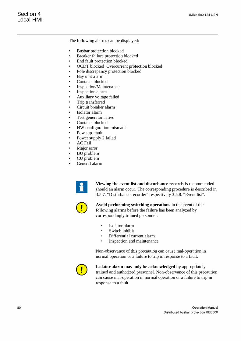
Section 4 1MRK 500 124-UENLocal HMI
80 Operation ManualDistributed busbar protection REB500
The following alarms can be displayed:
• Busbar protection blocked• Breaker failure protection blocked• End fault protection blocked• OCDT blocked Overcurrent protection blocked• Pole discrepancy protection blocked• Bay unit alarm• Contacts blocked• Inspection/Maintenance• Inspection alarm• Auxiliary voltage failed• Trip transferred• Circuit breaker alarm• Isolator alarm• Test generator active• Contacts blocked• HW configuration mismatch• Pow.sup. fault• Power supply 2 failed• AC Fail• Major error• BU problem• CU problem• General alarm
Viewing the event list and disturbance records is recommendedshould an alarm occur. The corresponding procedure is described in3.5.7. “Disturbance recorder” respectively 3.5.8. “Event list”.
Avoid performing switching operations in the event of thefollowing alarms before the failure has been analyzed bycorrespondingly trained personnel:
• Isolator alarm• Switch inhibit• Differential current alarm• Inspection and maintenance
Non-observance of this precaution can cause mal-operation innormal operation or a failure to trip in response to a fault.
Isolator alarm may only be acknowledged by appropriatelytrained and authorized personnel. Non-observance of this precautioncan cause mal-operation in normal operation or a failure to trip inresponse to a fault.

1MRK 500 124-UEN Section 4Local HMI
Operation Manual 81Distributed busbar protection REB500
4.5 Trips
The trips generated by REB500 can be viewed in the trip list together with theprotection functions that caused them (Menu “Trips” / first column of list). Inaddition the corresponding date/time information, source and values (if existing)can be displayed.
The following trips can appear on the local HMI
• TRIP(ITT): Trip: corresponding bus zones• BBP Trip: Phase related diff. and restr. currents• BFP TRIP T1: Current of each phase• BFP TRIP T2: Current of each phase• OCDT TRIP: Current• PDF TRIP: Current• EFP TRIP: Current• EXTERNAL TRIP• DIST TRIP: Zone (Zone 1,2,3,4, or Zone 5 for the ‘final zone’),
impedance and fault location• Further trip signal of Bay Protection (if existing)
All these information can be seen in the trip list by navigation via the right and leftarrow keys on the LHMI.
Table 20 Navigation within LHMI trip list
*1)
Trip *2) Date Source Value *3) *5)
Table 21 Example for a trip list viewed on Bay UnitTrip Date Source Value
BFP TRIP T1 2015-11-23 09:05:46 Bayname 1 L1 3604A L2 0A L3 0A L0 3604AOCDT TRIP 2015-11-23 09:05:46 Bayname 1 3604A - - -OCDT TRIP 4) 2015-11-23 09:05:46 Bayname 1 - - - -TRIP 2015-11-23 09:05:46 Bayname 1 - - - -
Table 22 Example for a trip list viewed on Central UnitTrip Date Source Value
BBP TRIP L1 2015-11-23 09:05:46 Zone BB01 Id = 3604A Ih = 3604ABFP TRIP T1 2015-11-23 09:05:46 Bayname 1 3604A - - -OCDT TRIP 2015-11-23 09:05:46 Bayname 1

Section 4 1MRK 500 124-UENLocal HMI
82 Operation ManualDistributed busbar protection REB500
Legend:
*1) Navigation via the right and left arrow keys on the LHMI (‘Value’ canhave entries in several columns)
*2) Trip signals column is fixed on left side of the trip list
*3) Value: information (number of columns) depends on the informationcontent of the trip signal
*4) Second OCDT TRIP is caused by the Bay Protection function (no valueentry available for this type of functions)
*5) Current value indications are generally instantaneous values
The red Protection indicator LED signals the trip state:
• Off: No pending trip in list• On: Pending or latched trips in list
The protection system and all signals can be reset by choosing “Clear” / “Reset alllatched LEDs and Lists” on the LHMI, or equivalently by setting the signal31810_External reset, e.g. generated by pressing the reset button.
1MRK 500 124-UEN Section 5WebHMI
Operation Manual 83Distributed busbar protection REB500
Section 5 WebHMI
5.1 Introduction
The WebHMI allows easy read-only access to all relevant details of a runningREB500 system, such as:
• - Switchgear status• - Event lists• - Analog measurements• - System data
5.2 Accessing the WebHMI
To access the WebHMI, browse to the following URL via the station bus (LAN0):
https://LAN_0_IP/reb500.html
Information: Access to the WebHMI is protected by the user management. Forrequired permissions, please refer to the Cyber Security Deployment Guideline.

Section 6 1MRK 500 124-UENTroubleshooting
84 Operation ManualDistributed busbar protection REB500
Section 6 Troubleshooting
6.1 Safety Instructions
All work on the REB500 busbar protection system must be carefullyplanned. Errors when manipulating the system cannot only destroycomponents, they can also cause false tripping and seriousinterruption to the power supply.
Precautions must be taken in the immediate area when working onthe central unit or one of the bay units to exclude any possibility ofpersons coming into contact with live parts.
A danger of electrical shock also exists when measuring currentsand voltages.
When replacing electronic modules, take the necessary precautionsto prevent damage to components due to electrostatic discharge(ESD).

1MRK 500 124-UEN Section 6 Troubleshooting
Operation Manual 85Distributed busbar protection REB500
6.2 List of faults and corrective actions
6.2.1 Useful LEDs on the IEDs and switches
The Fault and Power (P) LED of the Switch are found on the left side of the switch.The green link LED for optical and electrical connection is located on the electricalconnector. The same LEDs are also available on the back side of the switch.
Fig. 6.1 LED Indication on the back side of the switch
The Ready LED is on the top of the BU/CU. The Alarm Indicator LED is locatedin the right lower corner of the IED, integrated within the alarm button (see Section4.3.3 and 4.3.6).
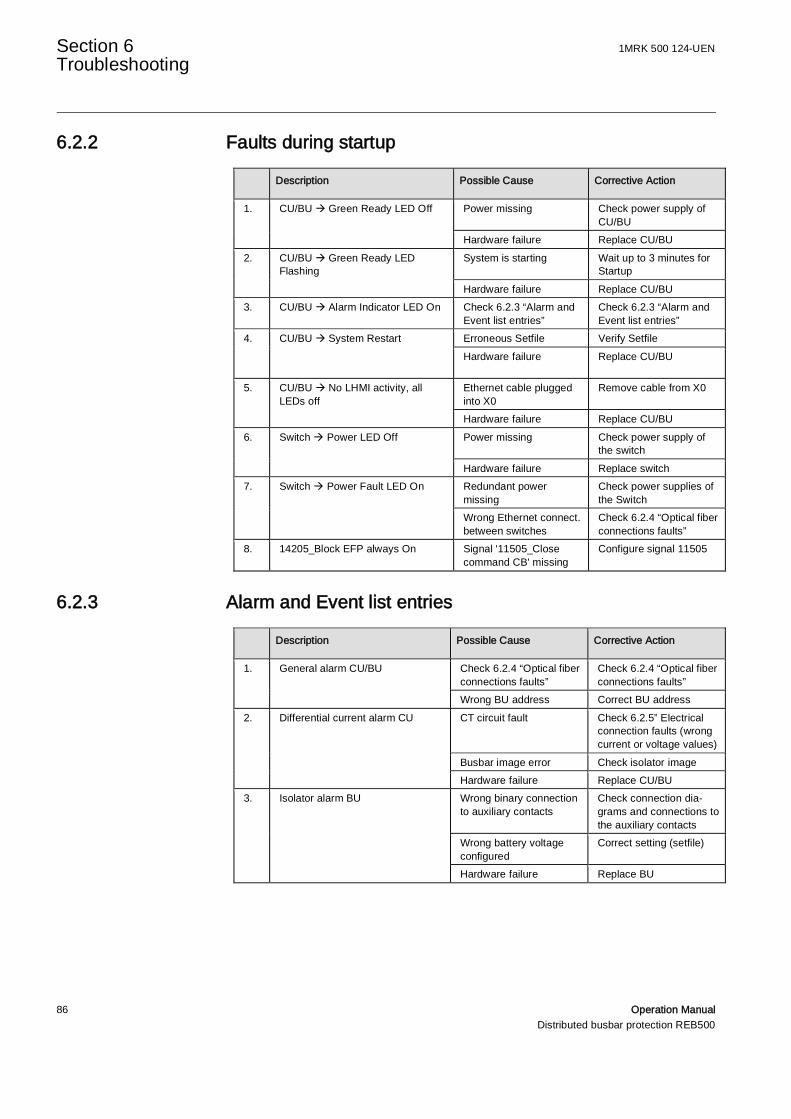
Section 6 1MRK 500 124-UENTroubleshooting
86 Operation ManualDistributed busbar protection REB500
6.2.2 Faults during startup
Description Possible Cause Corrective Action
1. CU/BU à Green Ready LED Off Power missing Check power supply ofCU/BU
Hardware failure Replace CU/BU2. CU/BU à Green Ready LED
FlashingSystem is starting Wait up to 3 minutes for
StartupHardware failure Replace CU/BU
3. CU/BU à Alarm Indicator LED On Check 6.2.3 “Alarm andEvent list entries”
Check 6.2.3 “Alarm andEvent list entries”
4. CU/BU à System Restart Erroneous Setfile Verify SetfileHardware failure Replace CU/BU
5. CU/BU à No LHMI activity, allLEDs off
Ethernet cable pluggedinto X0
Remove cable from X0
Hardware failure Replace CU/BU6. Switch à Power LED Off Power missing Check power supply of
the switchHardware failure Replace switch
7. Switch à Power Fault LED On Redundant powermissing
Check power supplies ofthe Switch
Wrong Ethernet connect.between switches
Check 6.2.4 “Optical fiberconnections faults”
8. 14205_Block EFP always On Signal '11505_Closecommand CB' missing
Configure signal 11505
6.2.3 Alarm and Event list entries
Description Possible Cause Corrective Action
1. General alarm CU/BU Check 6.2.4 “Optical fiberconnections faults”
Check 6.2.4 “Optical fiberconnections faults”
Wrong BU address Correct BU address2. Differential current alarm CU CT circuit fault Check 6.2.5” Electrical
connection faults (wrongcurrent or voltage values)
Busbar image error Check isolator imageHardware failure Replace CU/BU
3. Isolator alarm BU Wrong binary connectionto auxiliary contacts
Check connection dia-grams and connections tothe auxiliary contacts
Wrong battery voltageconfigured
Correct setting (setfile)
Hardware failure Replace BU
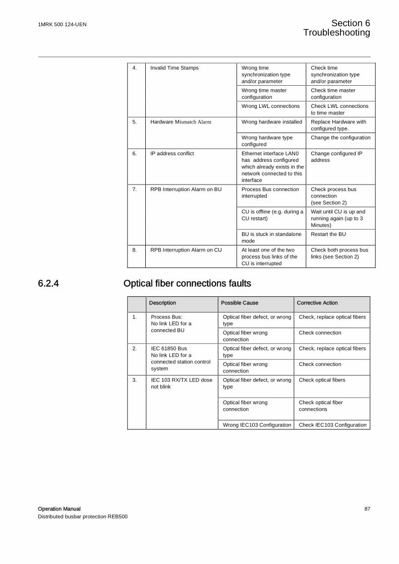
1MRK 500 124-UEN Section 6 Troubleshooting
Operation Manual 87Distributed busbar protection REB500
4. Invalid Time Stamps Wrong timesynchronization typeand/or parameter
Check timesynchronization typeand/or parameter
Wrong time masterconfiguration
Check time masterconfiguration
Wrong LWL connections Check LWL connectionsto time master
5. Hardware Mismatch Alarm Wrong hardware installed Replace Hardware withconfigured type.
Wrong hardware typeconfigured
Change the configuration
6. IP address conflict Ethernet interface LAN0has address configuredwhich already exists in thenetwork connected to thisinterface
Change configured IPaddress
7. RPB Interruption Alarm on BU Process Bus connectioninterrupted
Check process busconnection(see Section 2)
CU is offline (e.g. during aCU restart)
Wait until CU is up andrunning again (up to 3Minutes)
BU is stuck in standalonemode
Restart the BU
8. RPB Interruption Alarm on CU At least one of the twoprocess bus links of theCU is interrupted
Check both process buslinks (see Section 2)
6.2.4 Optical fiber connections faults
Description Possible Cause Corrective Action
1. Process Bus:No link LED for aconnected BU
Optical fiber defect, or wrongtype
Check, replace optical fibers
Optical fiber wrongconnection
Check connection
2. IEC 61850 BusNo link LED for aconnected station controlsystem
Optical fiber defect, or wrongtype
Check, replace optical fibers
Optical fiber wrongconnection
Check connection
3. IEC 103 RX/TX LED dosenot blink
Optical fiber defect, or wrongtype
Check optical fibers
Optical fiber wrongconnection
Check optical fiberconnections
Wrong IEC103 Configuration Check IEC103 Configuration
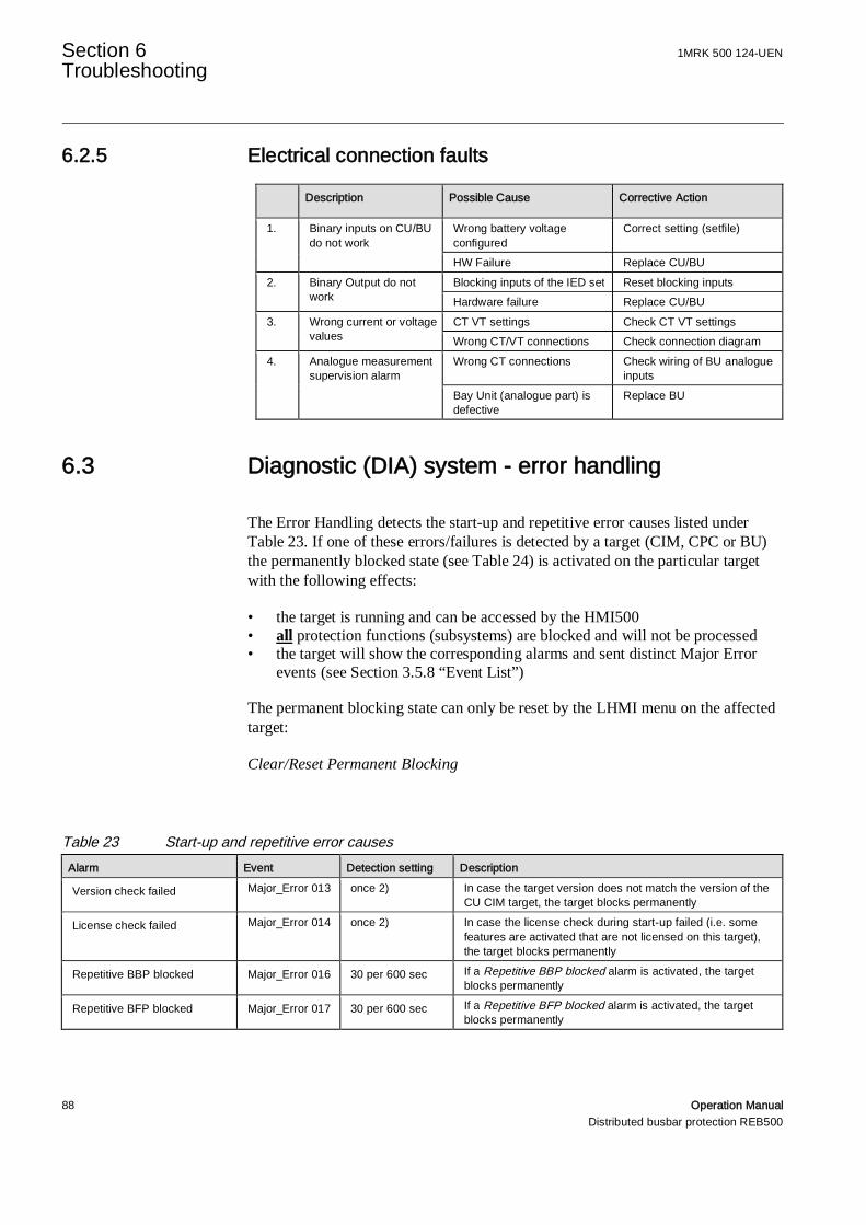
Section 6 1MRK 500 124-UENTroubleshooting
88 Operation ManualDistributed busbar protection REB500
6.2.5 Electrical connection faults
Description Possible Cause Corrective Action
1. Binary inputs on CU/BUdo not work
Wrong battery voltageconfigured
Correct setting (setfile)
HW Failure Replace CU/BU2. Binary Output do not
workBlocking inputs of the IED set Reset blocking inputsHardware failure Replace CU/BU
3. Wrong current or voltagevalues
CT VT settings Check CT VT settingsWrong CT/VT connections Check connection diagram
4. Analogue measurementsupervision alarm
Wrong CT connections Check wiring of BU analogueinputs
Bay Unit (analogue part) isdefective
Replace BU
6.3 Diagnostic (DIA) system - error handling
The Error Handling detects the start-up and repetitive error causes listed underTable 23. If one of these errors/failures is detected by a target (CIM, CPC or BU)the permanently blocked state (see Table 24) is activated on the particular targetwith the following effects:
• the target is running and can be accessed by the HMI500• all protection functions (subsystems) are blocked and will not be processed• the target will show the corresponding alarms and sent distinct Major Error
events (see Section 3.5.8 “Event List”)
The permanent blocking state can only be reset by the LHMI menu on the affectedtarget:
Clear/Reset Permanent Blocking
Table 23 Start-up and repetitive error causesAlarm Event Detection setting Description
Version check failed Major_Error 013 once 2) In case the target version does not match the version of theCU CIM target, the target blocks permanently
License check failed Major_Error 014 once 2) In case the license check during start-up failed (i.e. somefeatures are activated that are not licensed on this target),the target blocks permanently
Repetitive BBP blocked Major_Error 016 30 per 600 sec If a Repetitive BBP blocked alarm is activated, the targetblocks permanently
Repetitive BFP blocked Major_Error 017 30 per 600 sec If a Repetitive BFP blocked alarm is activated, the targetblocks permanently

1MRK 500 124-UEN Section 6 Troubleshooting
Operation Manual 89Distributed busbar protection REB500
Alarm Event Detection setting DescriptionRepetitive Diff Current Alarm Major_Error 018 60 per 3'600 sec If a Repetitive Diff Current Alarm is activated, the target
blocks permanentlyRepetitive Invalid BU Currents Major_Error 019 30 per 60 sec If a Repetitive Invalid BU Currents alarm is activated, the
target blocks permanentlyRepetitive Output Relaysblocked
Major_Error 020 30 per 600 sec If a Repetitive Output Relays blocked alarm is activated, thetarget blocks permanently
Repetitive BU restarts Major_Error 021 3 per 600 sec In case of Repetitive BU restarts, the target blockspermanently
Repetitive CU restarts Major_Error 022 3 per 600 sec In case of Repetitive CU restarts, the target blockspermanently
CIM HW Failure Major_Error 023 once 1) If the diagnosis detects any HW related failure, the CIMblocks permanently
CPC HW Failure Major_Error 024 once 1) If the diagnosis detects any HW related failure, the CPCblocks permanently
BU HW Failure Major_Error 025 once 1) If the diagnosis detects any HW related failure, the BUblocks permanently
Missing PSM HW Module Major_Error 026 once 2) If the required PSM HW module is missing, the target blockspermanently
Missing Red. PSM HW Module Major_Error 027 once 2) If the configured/required redundant PSM HW module ismissing, the target blocks permanently
Missing BIO HW Module Major_Error 028 once 2) If the configured/required BIO HW module is missing, thetarget blocks permanently
Missing TRM HW Module Major_Error 029 once 2) If the required TRM HW module is missing, the target blockspermanently
Missing PIO HW Module Major_Error 030 once 2) If the configured/required PIO HW module is missing, thetarget blocks permanently
Wrong TRM HW Module Major_Error 031 once 2) If the configured and physical assembled TRM HW moduledo not match, the target blocks permanently
Wrong PSM HW Module Major_Error 032 once 2) If the configured and physical assembled PSM HW moduledo not match, the target blocks permanently
Wrong Red. PSM HW Module Major_Error 033 once 2) If the configured and physical assembled redundant PSMHW module do not match, the target blocks permanently
BIO channels mismatch Major_Error 034 once 2) If binary input or output channels configured on physicalchannels that are not available, the target blockspermanently
IP address conflict Major_Error 075 once 2) If an IP address configuration problem occurs (The mainreason is that two interfaces are configured with the same IPaddress), the target blocks permanently
1) only once during start-up or normal running state2) only once during start-up
Table 24 Permanently blocked stateAlarm Event Detection setting Description
Permanently Blocked Major_Error 176 - If the error handling detects start-up or repetitive errorcauses (see Table 15), the permanently blocked state is set

Contact us
ABB ABSubstation Automation ProductsSE-721 59 VästeråsSwedenTelephone: +46 (0) 21 32 50 00Facsimile: +46 (0) 21 14 69 18http://www.abb.com/substationautomation
1MR
K50
012
4-U
EN-
©C
opyr
ight
2016
AB
B,A
llrig
htsr
eser
ved.
Related Documents