Research Paper Direct growth of hydrotalcite nanolayers on carbon fibers by electrospinning ☆ Luis B. Modesto-López a,1,2 , Ricardo J. Chimentão a,2 , Mayra G. Álvarez a,2 , Joan Rosell-Llompart a,b , Francisco Medina a, ⁎, Jordi Llorca c a Departament d'Enginyeria Química, Universitat Rovira i Virgili, Av. Països Catalans 26, E-43007 Tarragona, Spain b ICREA — Catalan Institution for Research and Advanced Studies, Pg. Lluís Companys 23, E-08010 Barcelona, Spain c Institute of Energy Technologies and Centre for Research in Nanoengineering, Technical University of Catalonia, Diagonal 647, E-08028 Barcelona, Spain abstract article info Article history: Received 13 September 2013 Received in revised form 25 June 2014 Accepted 2 July 2014 Available online xxxx Keywords: Carbon fibers Layered double hydroxide Electrospinning Glycerol Glycerol carbonate Basic centers Hydrotalcite (HT) nanolayers have been grown directly on carbon fibers by carbonization and subsequent hydra- tion of electrospun PVA/PEO/MgAl–nitrate fibers. The growth of the layered material was ascertained by X-ray diffraction and electron microscopy techniques. High resolution transmission electron microscopy indicated that HTs are adhered on the carbon fibers. The HTs presented very small crystallite sizes, which enhance the ac- cessibility of their basic centers compared to bulk HTs, leading to significant differences in terms of catalytic activity. © 2014 Elsevier B.V. All rights reserved. 1. Introduction Electrospinning is a versatile method for creating micro- and nanofiber-type templates from both polymeric and inorganic materials (Madhugiri et al., 2003, 2007; Li and Xia, 2004) as building blocks for membranes, sensors, catalysts and catalyst supports among others (Li and Xia, 2004). Typically, a suitable precursor is dissolved or suspended in a polymer–solvent mixture, and this mixture is pulled by an intense electric field into thin fibers (tens to thousands of nm in diameter). These polymeric template fibers can be thermally treated to transform any precursors into dispersed nanomaterials. An interesting material, which could be grown to nanometric size by this approach are hydrotalcites (HTs). Nanometric sized hydrotalcites have been synthesized over different supports for a number of applica- tions in gas permeable membranes (Lee et al., 2008), photodegradation (Wang et al., 2010), catalysis (Winter et al., 2005a, 2005b) and green chemistry (Álvarez et al., 2012, 2013). The broad applicability of these materials reflects the chemical versatility of the HT structure, which is constituted by positively charged brucite-like layers, neutralized by in- terlayer anions (Cavani et al., 1991; Evans and Duan, 2006). Recent studies in catalysis indicate that the active sites in HTs are located at the platelets' edges (Roelofs et al., 2000), whose exposed surface is determined by the lateral size of the crystallites. These materials have HT crystallite sizes around 20–30 nm, and are reported to improve the catalytic activity in several organic reactions compared to bulk hydrotalcites (Winter et al., 2005a, 2005b; Álvarez et al., 2012, 2013). Diverse techniques and supports have been used to synthesize sup- ported nanosized HTs, for example, co-precipitation on carbon nanofi- bers (Winter et al., 2005a, 2005b) or on alumina particles (Álvarez et al., 2012). Another example is the synthesis of nanosized HTs inside the channels of well-ordered mesoporous materials (Dubey, 2007; Li and Shi, 2008). In previous electrospinning works, pre-synthesized hydrotalcites have been mixed with polymer solutions and electrospun to produce polymer/HT composites for applications such as fiber reinforcement (Romeo et al., 2007; Zhao et al., 2008; Zhuo et al., 2011) or materials with improved thermal properties (Zhao et al., 2010). In those ap- proaches the HTs are encapsulated within the polymer matrix (Romeo et al., 2007; Zhao et al., 2008, 2010; Zhuo et al., 2011). However, until now, there are no reports on a direct synthesis of HTs supported on car- bonaceous materials using electrospun fibers. Here, electrospinning is proposed as a vector to introduce a hydro- talcite precursor directly throughout a fiber matrix. The nanosized HT Applied Clay Science xxx (2014) xxx–xxx ☆ Author Contributions: The manuscript was written through the contributions of all authors. ⁎ Corresponding author. E-mail address: [email protected] (F. Medina). 1 Current address: Department of Environmental Science, University of Eastern Finland, P.O. Box 1627, FI-70211 Kuopio, Finland. 2 These authors contributed equally. CLAY-03155; No of Pages 7 http://dx.doi.org/10.1016/j.clay.2014.07.037 0169-1317/© 2014 Elsevier B.V. All rights reserved. Contents lists available at ScienceDirect Applied Clay Science journal homepage: www.elsevier.com/locate/clay Please cite this article as: Modesto-López, L.B., et al., Direct growth of hydrotalcite nanolayers on carbon fibers by electrospinning, Appl. Clay Sci. (2014), http://dx.doi.org/10.1016/j.clay.2014.07.037

Welcome message from author
This document is posted to help you gain knowledge. Please leave a comment to let me know what you think about it! Share it to your friends and learn new things together.
Transcript
Applied Clay Science xxx (2014) xxx–xxx
CLAY-03155; No of Pages 7
Contents lists available at ScienceDirect
Applied Clay Science
j ourna l homepage: www.e lsev ie r .com/ locate /c lay
Research Paper
Direct growth of hydrotalcite nanolayers on carbon fibersby electrospinning☆
Luis B. Modesto-López a,1,2, Ricardo J. Chimentão a,2, Mayra G. Álvarez a,2, Joan Rosell-Llompart a,b,Francisco Medina a,⁎, Jordi Llorca c
a Departament d'Enginyeria Química, Universitat Rovira i Virgili, Av. Països Catalans 26, E-43007 Tarragona, Spainb ICREA — Catalan Institution for Research and Advanced Studies, Pg. Lluís Companys 23, E-08010 Barcelona, Spainc Institute of Energy Technologies and Centre for Research in Nanoengineering, Technical University of Catalonia, Diagonal 647, E-08028 Barcelona, Spain
☆ Author Contributions: The manuscript was written tauthors.⁎ Corresponding author.
E-mail address: [email protected] (F. Medina).1 Current address: Department of Environmental Scienc
P.O. Box 1627, FI-70211 Kuopio, Finland.2 These authors contributed equally.
http://dx.doi.org/10.1016/j.clay.2014.07.0370169-1317/© 2014 Elsevier B.V. All rights reserved.
Please cite this article as: Modesto-López, L.B(2014), http://dx.doi.org/10.1016/j.clay.2014
a b s t r a c t
a r t i c l e i n f oArticle history:Received 13 September 2013Received in revised form 25 June 2014Accepted 2 July 2014Available online xxxx
Keywords:Carbon fibersLayered double hydroxideElectrospinningGlycerolGlycerol carbonateBasic centers
Hydrotalcite (HT) nanolayers have been grown directly on carbon fibers by carbonization and subsequent hydra-tion of electrospun PVA/PEO/MgAl–nitrate fibers. The growth of the layered material was ascertained by X-raydiffraction and electron microscopy techniques. High resolution transmission electron microscopy indicatedthat HTs are adhered on the carbon fibers. The HTs presented very small crystallite sizes, which enhance the ac-cessibility of their basic centers compared to bulk HTs, leading to significant differences in terms of catalyticactivity.
© 2014 Elsevier B.V. All rights reserved.
1. Introduction
Electrospinning is a versatile method for creating micro- andnanofiber-type templates from both polymeric and inorganic materials(Madhugiri et al., 2003, 2007; Li and Xia, 2004) as building blocks formembranes, sensors, catalysts and catalyst supports among others (Liand Xia, 2004). Typically, a suitable precursor is dissolved or suspendedin a polymer–solvent mixture, and this mixture is pulled by an intenseelectric field into thin fibers (tens to thousands of nm in diameter).These polymeric template fibers can be thermally treated to transformany precursors into dispersed nanomaterials.
An interestingmaterial, which could be grown to nanometric size bythis approach are hydrotalcites (HTs). Nanometric sized hydrotalciteshave been synthesized over different supports for a number of applica-tions in gas permeable membranes (Lee et al., 2008), photodegradation(Wang et al., 2010), catalysis (Winter et al., 2005a, 2005b) and greenchemistry (Álvarez et al., 2012, 2013). The broad applicability of thesematerials reflects the chemical versatility of the HT structure, which is
hrough the contributions of all
e, University of Eastern Finland,
., et al., Direct growth of hydr.07.037
constituted by positively charged brucite-like layers, neutralized by in-terlayer anions (Cavani et al., 1991; Evans and Duan, 2006). Recentstudies in catalysis indicate that the active sites in HTs are located atthe platelets' edges (Roelofs et al., 2000), whose exposed surface isdetermined by the lateral size of the crystallites. These materials haveHT crystallite sizes around 20–30 nm, and are reported to improve thecatalytic activity in several organic reactions compared to bulkhydrotalcites (Winter et al., 2005a, 2005b; Álvarez et al., 2012, 2013).
Diverse techniques and supports have been used to synthesize sup-ported nanosized HTs, for example, co-precipitation on carbon nanofi-bers (Winter et al., 2005a, 2005b) or on alumina particles (Álvarezet al., 2012). Another example is the synthesis of nanosized HTs insidethe channels of well-ordered mesoporous materials (Dubey, 2007; Liand Shi, 2008).
In previous electrospinning works, pre-synthesized hydrotalciteshave been mixed with polymer solutions and electrospun to producepolymer/HT composites for applications such as fiber reinforcement(Romeo et al., 2007; Zhao et al., 2008; Zhuo et al., 2011) or materialswith improved thermal properties (Zhao et al., 2010). In those ap-proaches the HTs are encapsulated within the polymer matrix (Romeoet al., 2007; Zhao et al., 2008, 2010; Zhuo et al., 2011). However, untilnow, there are no reports on a direct synthesis of HTs supported on car-bonaceous materials using electrospun fibers.
Here, electrospinning is proposed as a vector to introduce a hydro-talcite precursor directly throughout a fiber matrix. The nanosized HT
otalcite nanolayers on carbon fibers by electrospinning, Appl. Clay Sci.

Transesterification of glycerol
1. Fiber templating by electrospinning
2. Carbonization
Preparation of electrospinning solution:
Mg-Al mixed oxidessupported on carbon fibers
3. Hydration
Hydrotalcites supported on carbon fibers (HT-CFs)
PVA/PEO (blank)
PVA/PEO/MgAl precursor
Carbon fibers
Chart 1. Procedure for the synthesis and activity test of hydrotalcites supported on carbonfibers (HT-CFs) and HT-free carbon fibers.
2 L.B. Modesto-López et al. / Applied Clay Science xxx (2014) xxx–xxx
is prepared in situ by thermal treatment and subsequent hydration ofthe precursor fiber. The confined space of the microstructured fibroustemplate ought to help in limiting the size of the HT crystallites towithin a few tens of nanometers.
Specifically, our approach consists of electrospinning a uniformaqueous solution containing a polymer matrix and nitrates of Mg andAl as HT precursors. The as-spun fibers are thermally treated in aninert atmosphere to carbonize the polymer simultaneously formingMg–Al mixed oxides. Subsequently, the hydrotalcite nanolayers aregrown upon hydration of the mixed oxides.
The morphology and composition of the resulting materials havebeen characterized after each synthesis step. In addition, the catalyticbehavior of these HT supported on carbon fiber (HT-CF) materials hasbeen tested in the transesterification of glycerol with diethyl carbonate,which is an innovative process to obtain valuable chemicals from non-petrochemical sources.
2. Experimental
2.1. Materials
Poly(vinyl alcohol) [PVA, 99%, hydrolyzed, Mw 30,000–50,000],poly(ethylene oxide) [PEO; Mw 600,000], Mg(NO3)2·6H2O, andAl(NO3)3·9H2O were purchased from Sigma-Aldrich. Except for PVA(see Subsection 2.2) all the chemicals were used as received. Deionized(DI) water was used as the solvent.
To perform the catalytic tests, glycerol (gly) (99%), diethyl carbonate(DEC) (99.5%, GC grade) and ethanol (98%), all purchased from Aldrich,were used without any further purification.
2.2. Preparation of electrospinning solutions
Initial experiments indicated the presence of Na species in the finalcarbon fiber-supported materials. These Na species were traced to thePVA as purchased. Therefore, a Na removal procedure reported in theliterature (Shin et al., 2008) was implemented prior to the preparationof electrospinnable solutions (see Supporting Information).
For a typical experiment, aqueous solutions of Na-free PVA/PEO andof Mg(NO3)2·6H2O/Al(NO3)3·9H2O (Mg:Al ratio = 2:1) were preparedseparately. First, the polymer solution was stirred vigorously in a waterbath at 353 K, using a hot plate, until a uniform solution was obtained(overnight). Then, the Mg–Al precursor solution was added to the firstsolution under continuous stirring at 353 K; after approximately 1 hthe temperature was turned off and the solution was ready forelectrospinning experiments. The PVA/PEO/MgAl precursor solutionwas composed of 14.3 wt.% PVA, 2.14 wt.% PEO, 2.90 wt.% Mg(NO3)2·6H2O, and 2.12 wt.% Al(NO3)3·9H2O. The PVA/PEO solution com-prised 19 wt.% PVA and 4 wt.% PEO. In both solutions the PVA/PEOweight ratio was kept constant at ~4.6. The solutions were preparedunder ambient conditions. PEO was added to improve the spinnabilityof the solution by reducing its surface tension. When the Mg and Alprecursors were added to the electrospinning solution we observed aprogressive decrease in the solution viscosity. Thus, electrospinningexperiments were conducted using fresh solutions.
2.3. Synthesis of HTs and their activity
The synthesis of HTs, from PVA/PEO/MgAl fibers is divided intothree steps and is summarized in Chart 1: (1) fiber templating byelectrospinning, (2) formation of mixed oxides on carbon fibers by car-bonization, and (3) formation of HTs supported on carbon fibers by hy-dration. In the case of PVA/PEO fibers, the synthesis finished after thecarbonization step. The activity of HT-CFs in the transesterification ofglycerol with diethyl carbonate was compared with that of bulk HTsand of control fibers. After each of the three main steps, the fibrous
Please cite this article as: Modesto-López, L.B., et al., Direct growth of hydr(2014), http://dx.doi.org/10.1016/j.clay.2014.07.037
materials were characterized bymicroscopy, spectroscopy, and adsorp-tion techniques (see Subsection 2.4).
2.3.1. Fiber template generation and collectionBoth PVA/PEO fibers containingMg and Al precursors (termed here-
inafter PVA/PEO/MgAl fibers) and PVA/PEO fibers were produced usingthe following method. In a typical experiment, 1 mL of electrospinningsolution was fed with a syringe pump through a square-ended stainlesssteel needle (300 μm outer diameter, G21) at a rate of 0.5 mL/h. Theneedle was connected to an 18 kV high voltage source. The fiberswere collected on a Si-wafer, which was supported on a stainless steelplate placed perpendicular to the needle main axis. The distance fromthe tip of the needle to the collector electrode was typically 11 cm.The electrospinning was run continuously until ~2 g of fibrous ma-terial was collected, and only stopped to re-charge the syringe withelectrospinning solution. The as-spun fiber mats were then dried invacuum overnight to remove any trapped solvent.
2.3.2. Synthesis of hydrotalcites supported on carbon fibers (HT-CFs)As-spun PVA/PEO and PVA/PEO/MgAl fiber mats were first
pyrolyzed in a quartz fixed bed reactor under Ar flow (20 mL/min)(carbonization step of Chart 1). The sample temperature was increasedfrom room temperature to 723 K at 5 K/min and kept at 723 K for 5 h.PVA/PEO fibers turned into carbon fibers (CFs) and PVA/PEO/MgAl fi-bers into Mg–Al mixed oxides supported on carbon fibers (MgAlOx-CFs). The system was then cooled down in an Ar flow to room temper-ature. Subsequently (hydration step of Chart 1), the MgAlOx-CFs werehydrated by exposing them to an Ar flow saturated (100 mL/min)with decarbonated water for 72 h at room temperature to obtain theMg–Al hydrotalcite structure (i.e., HT-CFs).
2.3.3. Transesterification of glycerolTransesterification reactions were performed in a 10 mL round-
bottomed flask equipped with a condenser. Typically, the flaskswere charged with an excess of DEC (DEC:glycerol molar ratio of16) to shift the equilibrium toward the formation of glycerol carbon-ate. Freshly activated catalyst (40 mg) was added and the experi-ment started with mechanical stirring under argon at 403 K. Stirringwas continued up to 10 h and 5mLof ethanolwas then added. The sam-ple was filtered and quantified by gas chromatography equippedwith aFID and the products were identified by GC coupled with a quadrupolemass analyzer. This was performed on a Shimadzu QP 2010 apparatuswith a Zebron ZW-WAX capillary column. The results were confirmedby 1H NMR.
otalcite nanolayers on carbon fibers by electrospinning, Appl. Clay Sci.
3L.B. Modesto-López et al. / Applied Clay Science xxx (2014) xxx–xxx
2.4. Characterization techniques
The morphology of fiber mats and the fiber diameters were investi-gated using scanning electron microscopy (SEM, JEOL JSM-35C).Samples were metalized with gold (~20 nm) before SEM analyses. Anenergy dispersive spectroscope (EDS) attached to the scanning micro-scope was employed to determine the elemental composition of thesamples. The sizes of electrospun fibers were obtained bymeasurementof several SEM images.
X-ray diffraction data of the fibers were recorded using a SiemensD5000 diffractometer (Bragg–Brentanoparafocusing geometry and ver-tical θ–θ goniometer) fitted with a grazing incidence (ω: 0.52°) attach-ment for thin film analysis and scintillation counter as a detector. Thedata were collected with an angular step of 0.05° at 6 s per step andsample rotation. Cu Kα radiation (λ = 1.54056 Å) was obtained froma copper X-ray tube operated at 40 kV and 30 mA. Patterns wereidentified using files from the Joint Committee on Powder DiffractionStandards (JCPDS). The samples were dispersed on a Si (510) sampleholder. The 2θ diffraction angle ranged between 5° and 90°.
The prepared materials were also characterized with TEM andHRTEM techniques. Transmission electron microscopy (TEM) wasperformed in a JEOL 1011 apparatus using 100 kV accelerating voltage.The samples were dispersed, without use of solvents, on a standard3 mm holey carbon-coated copper grid. High-resolution TEM (HRTEM)was performed on a JEOL 2010 instrument operated at 200 kV and
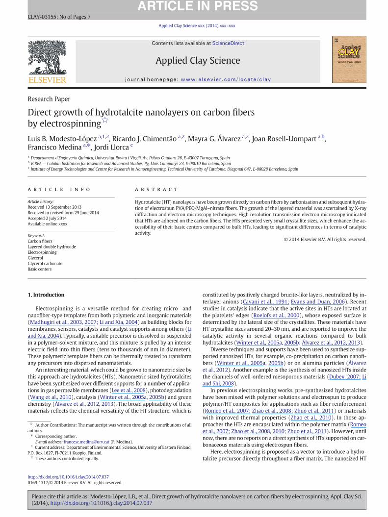
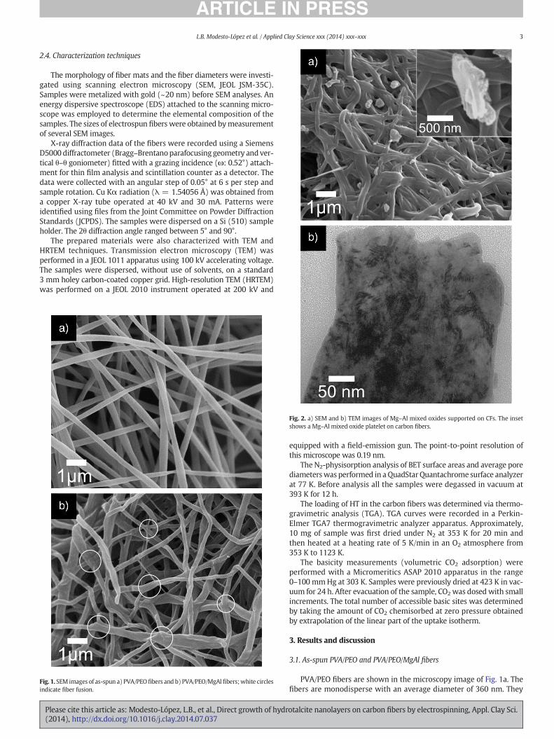
Fig. 1. SEM images of as-spun a) PVA/PEOfibers and b) PVA/PEO/MgAlfibers;white circlesindicate fiber fusion.
Fig. 2. a) SEM and b) TEM images of Mg–Al mixed oxides supported on CFs. The insetshows a Mg–Al mixed oxide platelet on carbon fibers.
Please cite this article as: Modesto-López, L.B., et al., Direct growth of hydr(2014), http://dx.doi.org/10.1016/j.clay.2014.07.037
equipped with a field-emission gun. The point-to-point resolution ofthis microscope was 0.19 nm.
The N2-physisorption analysis of BET surface areas and average porediameterswas performed in a QuadStarQuantachrome surface analyzerat 77 K. Before analysis all the samples were degassed in vacuum at393 K for 12 h.
The loading of HT in the carbon fibers was determined via thermo-gravimetric analysis (TGA). TGA curves were recorded in a Perkin-Elmer TGA7 thermogravimetric analyzer apparatus. Approximately,10 mg of sample was first dried under N2 at 353 K for 20 min andthen heated at a heating rate of 5 K/min in an O2 atmosphere from353 K to 1123 K.
The basicity measurements (volumetric CO2 adsorption) wereperformed with a Micromeritics ASAP 2010 apparatus in the range0–100 mmHg at 303 K. Samples were previously dried at 423 K in vac-uum for 24 h. After evacuation of the sample, CO2 was dosed with smallincrements. The total number of accessible basic sites was determinedby taking the amount of CO2 chemisorbed at zero pressure obtainedby extrapolation of the linear part of the uptake isotherm.
3. Results and discussion
3.1. As-spun PVA/PEO and PVA/PEO/MgAl fibers
PVA/PEO fibers are shown in the microscopy image of Fig. 1a. Thefibers are monodisperse with an average diameter of 360 nm. They
otalcite nanolayers on carbon fibers by electrospinning, Appl. Clay Sci.
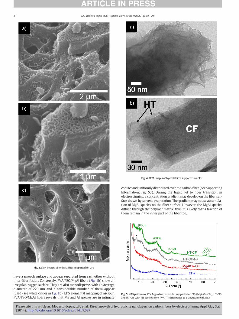
Fig. 4. TEM images of hydrotalcites supported on CFs.
Fig. 3. SEM images of hydrotalcites supported on CFs.
Fig. 5. XRD patterns of CFs, Mg–Al mixed oxides supported on CFs (MgAlOx-CFs), HT-CFs,and HT-CFs with Na species from PVA. (* corresponds to diaoyudaoite phase.)
4 L.B. Modesto-López et al. / Applied Clay Science xxx (2014) xxx–xxx
have a smooth surface and appear separated from each other withoutinter-fiber fusion. Conversely, PVA/PEO/MgAl fibers (Fig. 1b) show anirregular, rugged surface. They are also monodisperse, with an averagediameter of 220 nm and a considerable number of them appearfused (see white circles in Fig. 1b). EDS elemental mapping of as-spunPVA/PEO/MgAl fibers reveals that Mg and Al species are in intimate
Please cite this article as: Modesto-López, L.B., et al., Direct growth of hydr(2014), http://dx.doi.org/10.1016/j.clay.2014.07.037
contact and uniformly distributed over the carbon fiber (see SupportingInformation, Fig. S3). During the liquid jet to fiber transition inelectrospinning, a concentration gradient may develop on the fiber sur-face drawn by solvent evaporation. The gradient may cause accumula-tion of MgAl species on the fiber surface. However, the MgAl speciesdiffuse through the polymer matrix, thus it is likely that a fraction ofthem remain in the inner part of the fiber too.
otalcite nanolayers on carbon fibers by electrospinning, Appl. Clay Sci.

Fig. 7. Thermograms of unsupported HT (HTbulk) and HT-CF hybrid samples. Dotted linescorrespond to a repeated analysis (HT-CFrep).
5L.B. Modesto-López et al. / Applied Clay Science xxx (2014) xxx–xxx
The addition of electrolytes is known to affect the viscosity of poly-mer solutions (Briscoe et al., 1996, 2000). Inorganic salts increase theelectrical conductivity of solutions, and typically, the fibermean diame-ter decreases with increasing the solution's electrical conductivity(Sigmund et al., 2006). Both, the reduced viscosity and the higher elec-trical conductivity, compared to those of the PVA/PEO solution, mayallow greater stretching of the fiber to thinner widths, as observed inFig. 1. Other authors have also reported these effects of electrospunPEO fibers when the solution contained inorganic salts (Arayanarakulet al., 2006). Fusion indicates that the fibers contain some amount ofsolvent when they are collected.
3.2.Mg–Almixed oxides (Mg–Al–Ox) and hydrotalcites (HTs) supported oncarbon fibers
Carbonization of PVA/PEO/MgAl fibers resulted in Mg–Al mixedoxides supported on carbon fibers (MgAlOx-CFs), shown in Fig. 2a.The fibers appear more fused than prior to carbonization (Fig. 1b).This is consistent with the expected softening of PVA and PEO at tem-peratures beyond theirmeltingpoint (~490K and ~340K, respectively).In addition, irregularly shaped particles appear on the fibers' surface.
Fig. 6. HRTEM images: a) hydrotalcite/carbon support interface with HT layers orientedperpendicular to the electron beam, b) interlayer spacing of HT layers.
Please cite this article as: Modesto-López, L.B., et al., Direct growth of hydr(2014), http://dx.doi.org/10.1016/j.clay.2014.07.037
Based on the carbonization conditions (723 K and Ar flow) and onEDS analyses they are believed to be Mg–Al mixed oxides (seeSupporting Information). The oxygen required to form these oxidescould be provided from the decomposition of the inorganic salt precur-sors and the polymermatrix (PVA and PEO). The inset of Fig. 2a shows amagnified view of one of those particles, which has a platelet form. TEManalyses reveal non-uniformities or “dark islands” on the carbon fibersurface, probably due to the Mg–Al mixed oxide species (Fig. 2b). EDSanalyses indicated that the only elements present in the fibers were,as expected, Mg, Al, O, and C, and that the Mg:Al molar ratio of 2:1was maintained in the MgAlOx-CFs (see Supporting Information).
Hydration of MgAlOx-CFs results in the formation of agglomeratedplate-like structures that resemble HTs (Fig. 3a). These structures areheterogeneously distributed through the CF network. They grow bothover the carbon fiber surface (Fig. 3b), and within the voids of the CFnetwork (Fig. 3c).
TEM analyses of the hydrated MgAlOx-CFs show a layered materialover the surface of a carbon fiber fragment (Fig. 4a). Nevertheless, thefiber is not observed due to a large number density of layers, whichare characteristic of hydrotalcites (Rives, 2001). Fig. 4b, however,shows another TEM image with fewer layers, in which the support CFis appreciated. In this figure, layers appear to grow from the fiber.
Under the hydration conditions used in this work, hydrotalcite(meixnerite-type) is expected to form (Pérez-Ramírez et al., 2007).The formation of HT-CFs is also confirmed by XRD. In Fig. 5 the charac-teristic peaks of HT are observed at 2Θ angles 11.2°, 23.4°, 35.1°, 61.1°,and 62.3°, corresponding to the (003), (006), (012), (110) and (113)planes, respectively (Cavani et al., 1991). In the case of MgAlOx-CFsonly the characteristic broad peak of carbon is observed, indicatingpoor crystallinity of these MgAlOxs. For reference, the XRD pattern ofthe HT-CFs with Na species (from as-received PVA, see Subsection 2.2)is also depicted in Fig. 5. In that case, the characteristic peaks ofhydrotalcites are observed too; however, the peak at 2Θ ~ 7° indicatesthe presence of a Na aluminate (diaoyudaoite).
High resolution TEM images reveal amorphous fiber structurescovered by a crystalline layer of about 10–20 nm thick (Fig. 6) andonly HTs attached to the fibers were observed, thus confirming the pre-vious SEM and TEM analyses (Figs. 3 & 4). The crystalline layer containshydrotalcite crystallites of about 4–8 nm in size. These values corre-spond to the thickness of HT platelets, which allows an estimate of thenumber of layers making up the sheet as about 10, in agreement withvalues reported by Winter et al. (2005a,b), and being definitely muchsmaller than those of bulk HTs (~400 sheets) (Erickson et al., 2005). Ahigh-magnification HRTEM image is provided in Fig. 6b, which showsthe area enclosed in the white rectangle of Fig. 6a. The image shows
otalcite nanolayers on carbon fibers by electrospinning, Appl. Clay Sci.
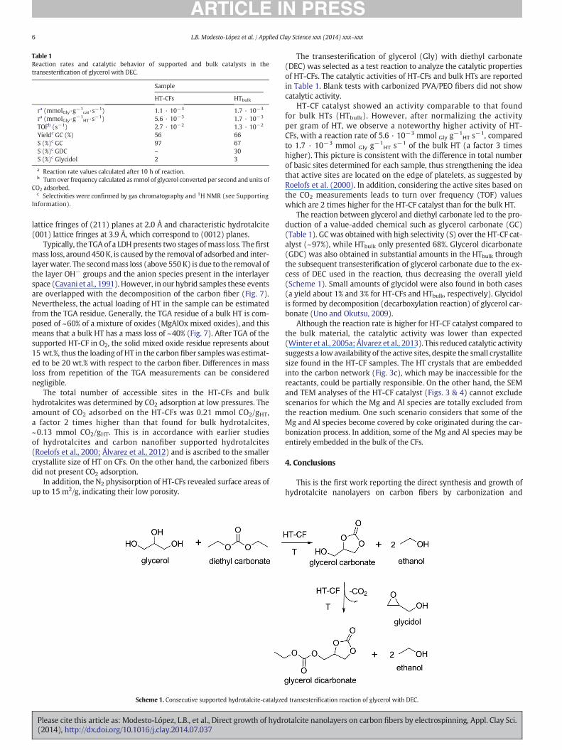
Table 1Reaction rates and catalytic behavior of supported and bulk catalysts in thetransesterification of glycerol with DEC.
Sample
HT-CFs HTbulk
ra (mmolGly·g−1cat·s−1) 1.1 · 10−3 1.7 · 10−3
ra (mmolGly·g−1HT·s−1) 5.6 · 10−3 1.7 · 10−3
TOFb (s−1) 2.7 · 10−2 1.3 · 10−2
Yieldc GC (%) 56 66S (%)c GC 97 67S (%)c GDC – 30S (%)c Glycidol 2 3
a Reaction rate values calculated after 10 h of reaction.b Turn over frequency calculated asmmol of glycerol converted per second and units of
CO2 adsorbed.c Selectivities were confirmed by gas chromatography and 1H NMR (see Supporting
Information).
6 L.B. Modesto-López et al. / Applied Clay Science xxx (2014) xxx–xxx
lattice fringes of (211) planes at 2.0 Å and characteristic hydrotalcite(001) lattice fringes at 3.9 Å, which correspond to (0012) planes.
Typically, the TGA of a LDH presents two stages ofmass loss. Thefirstmass loss, around450K, is caused by the removal of adsorbed and inter-layerwater. The secondmass loss (above 550 K) is due to the removal ofthe layer OH− groups and the anion species present in the interlayerspace (Cavani et al., 1991). However, in our hybrid samples these eventsare overlapped with the decomposition of the carbon fiber (Fig. 7).Nevertheless, the actual loading of HT in the sample can be estimatedfrom the TGA residue. Generally, the TGA residue of a bulk HT is com-posed of ~60% of a mixture of oxides (MgAlOx mixed oxides), and thismeans that a bulk HT has a mass loss of ~40% (Fig. 7). After TGA of thesupported HT-CF in O2, the solid mixed oxide residue represents about15 wt.%, thus the loading of HT in the carbon fiber sampleswas estimat-ed to be 20 wt.% with respect to the carbon fiber. Differences in massloss from repetition of the TGA measurements can be considerednegligible.
The total number of accessible sites in the HT-CFs and bulkhydrotalcites was determined by CO2 adsorption at low pressures. Theamount of CO2 adsorbed on the HT-CFs was 0.21 mmol CO2/gHT,a factor 2 times higher than that found for bulk hydrotalcites,~0.13 mmol CO2/gHT. This is in accordance with earlier studiesof hydrotalcites and carbon nanofiber supported hydrotalcites(Roelofs et al., 2000; Álvarez et al., 2012) and is ascribed to the smallercrystallite size of HT on CFs. On the other hand, the carbonized fibersdid not present CO2 adsorption.
In addition, the N2 physisorption of HT-CFs revealed surface areas ofup to 15 m2/g, indicating their low porosity.
Scheme 1. Consecutive supported hydrotalcite-catalyze
Please cite this article as: Modesto-López, L.B., et al., Direct growth of hydr(2014), http://dx.doi.org/10.1016/j.clay.2014.07.037
The transesterification of glycerol (Gly) with diethyl carbonate(DEC) was selected as a test reaction to analyze the catalytic propertiesof HT-CFs. The catalytic activities of HT-CFs and bulk HTs are reportedin Table 1. Blank tests with carbonized PVA/PEO fibers did not showcatalytic activity.
HT-CF catalyst showed an activity comparable to that foundfor bulk HTs (HTbulk). However, after normalizing the activityper gram of HT, we observe a noteworthy higher activity of HT-CFs, with a reaction rate of 5.6 · 10−3 mmol Gly g−1
HT s−1, comparedto 1.7 · 10−3 mmol Gly g−1
HT s−1 of the bulk HT (a factor 3 timeshigher). This picture is consistent with the difference in total numberof basic sites determined for each sample, thus strengthening the ideathat active sites are located on the edge of platelets, as suggested byRoelofs et al. (2000). In addition, considering the active sites based onthe CO2 measurements leads to turn over frequency (TOF) valueswhich are 2 times higher for the HT-CF catalyst than for the bulk HT.
The reaction between glycerol and diethyl carbonate led to the pro-duction of a value-added chemical such as glycerol carbonate (GC)(Table 1). GC was obtained with high selectivity (S) over the HT-CF cat-alyst (~97%), while HTbulk only presented 68%. Glycerol dicarbonate(GDC) was also obtained in substantial amounts in the HTbulk throughthe subsequent transesterification of glycerol carbonate due to the ex-cess of DEC used in the reaction, thus decreasing the overall yield(Scheme 1). Small amounts of glycidol were also found in both cases(a yield about 1% and 3% for HT-CFs and HTbulk, respectively). Glycidolis formed by decomposition (decarboxylation reaction) of glycerol car-bonate (Uno and Okutsu, 2009).
Although the reaction rate is higher for HT-CF catalyst compared tothe bulk material, the catalytic activity was lower than expected(Winter et al., 2005a; Álvarez et al., 2013). This reduced catalytic activitysuggests a low availability of the active sites, despite the small crystallitesize found in the HT-CF samples. The HT crystals that are embeddedinto the carbon network (Fig. 3c), which may be inaccessible for thereactants, could be partially responsible. On the other hand, the SEMand TEM analyses of the HT-CF catalyst (Figs. 3 & 4) cannot excludescenarios for which the Mg and Al species are totally excluded fromthe reaction medium. One such scenario considers that some of theMg and Al species become covered by coke originated during the car-bonization process. In addition, some of the Mg and Al species may beentirely embedded in the bulk of the CFs.
4. Conclusions
This is the first work reporting the direct synthesis and growth ofhydrotalcite nanolayers on carbon fibers by carbonization and
d transesterification reaction of glycerol with DEC.
otalcite nanolayers on carbon fibers by electrospinning, Appl. Clay Sci.
7L.B. Modesto-López et al. / Applied Clay Science xxx (2014) xxx–xxx
subsequent hydration of electro-spun PVA/PEO/MgAl–nitrate fibers.The resulting material comprised fibrous support that was coveredwith a thin layer of HT (~10 to ~50 nm thick). Such carbon-supportedHT nanolayers displayed a larger number of accessible active sitesthan bulk HT in the transesterification test reaction of glycerol withdiethyl carbonate. However, the catalytic activity of these HT-CFmaterials is not as high as expected based on the actual HT loading,either because of embedded HTs or the presence of coke.
Acknowledgment
This work was financially supported by the Spanish Governmentthrough grants CTQ2008-05758/PPQ, DPI2012-35687, CTQ2008-02043-E, and JCI-2010-07328 and by the Government of Catalonia,grant 2009-SGR-1529. F. Medina and J. Llorca also acknowledge theICREA ACADEMIA from the Catalan Government.
Appendix A. Supplementary data
Supplementary data to this article can be found online at http://dx.doi.org/10.1016/j.clay.2014.07.037.
References
Álvarez, M.G., Plíšková, M., Segarra, A.M., Medina, F., Figueras, F., 2012. Synthesis ofglycerol carbonates by transesterification of glycerol in a continuous system usingsupported hydrotalcites as catalysts. Appl. Catal. B Environ. 113–114, 212–220.
Álvarez, M.G., Frey, A.M., Bitter, J.H., Segarra, A.M., de Jong, K.P., Medina, F., 2013. On therole of the activation procedure of supported hydrotalcites for base catalyzedreactions: glycerol to glycerol carbonate and self-condensation of acetone. Appl.Catal. B Environ. 134–135, 231–237.
Arayanarakul, K., Choktaweesap, N., Aht-ong, D., Meechaisue, C., Supaphol, P., 2006.Effects of poly(ethylene glycol), inorganic salt, sodium dodecyl sulphate and solventsystem on electrospinning of poly(ethylene oxide). Macromol. Mater. Eng. 291,581–591.
Briscoe, B., Luckham, P., Zhu, S., 1996. Rheological study of poly(ethylene oxide) inaqueous salt solutions at high temperature and pressure. Macromolecules 29,6208–6211.
Briscoe, B., Luckham, P., Zhu, S., 2000. The effects of hydrogen bonding upon the viscosityof aqueous poly(vinyl alcohol) solutions. Polymer 41, 3851–3860.
Cavani, F., Trifirò, F., Vaccari, A., 1991. Hydrotalcite-type anionic clays: preparation,properties and applications. Catal. Today 11, 173–301.
Dubey, A., 2007. Synthesis and catalytic applications of CMK-LDH (layered doublehydroxides) nanocomposite materials. Green Chem. 9, 424–426.
Please cite this article as: Modesto-López, L.B., et al., Direct growth of hydr(2014), http://dx.doi.org/10.1016/j.clay.2014.07.037
Erickson, K.L., Bostrom, T.E., Frost, R.L., 2005. A study of structural memory effects insynthetic hydrotalcites using environmental SEM. Mater. Lett. 59, 226–229.
Evans, D.G., Duan, X., 2006. Preparation of layered double hydroxides and their applica-tions as additives in polymers, as precursors to magnetic materials and in biologyand medicine. Chem. Commun. 485–496.
Lee, J.H., Nam, H.J., Rhee, S.W., Jung, D.Y., 2008. Hybrid assembly of layered doublehydroxide nanocrystals with inorganic, polymeric and biomaterials form micro- tonanometer scales. Eur. J. Inorg. Chem. 5573–5578.
Li, L., Shi, J., 2008. In situ assembly of layered double hydroxide nano-crystallites withinsilica mesopores and its high solid base catalytic activity. Chem. Commun. 996–998.
Li, D., Xia, Y., 2004. Electrospinning nanofibers: reinventing the wheel? Adv. Mater. 16,1151–1170.
Madhugiri, S., Dalton, A., Gutierrez, J., Ferraris, J.P., Balkus Jr., K.J., 2003. Electrospun MEH-PPV/SBA-15 composite nanofibers using a dual syringe method. J. Am. Chem. Soc.125, 14531–14538.
Madhugiri, S., Ferraris, J.P., Balkus Jr., K.J., 2007. Electrospun polyethylene–hectorite claycomposite fibers. Int. J. Electrospun Nanofibers Appl. 1, 89–102.
Pérez-Ramírez, J., Abelló, S., van der Pers, N.M., 2007. Memory effect of activated Mg–Alhydrotalcite: in situ XRD studies during decomposition and gas-phase reconstruction.Chem. Eur. J. 13, 870–878.
Rives, V., 2001. Layered Double Hydroxides: Present and Future. In: Rives, V. (Ed.), NovaScience Publishers Co., Inc., New York.
Roelofs, J.C.A.A., Jos van Dillen, A., de Jong, K.P., 2000. Base-catalyzed condensation of citraland acetone at low temperature using modified hydrotalcite catalysts. Catal. Today60, 297–303.
Romeo, V., Gorrasi, G., Vittoria, V., Chronakis, I.S., 2007. Encapsulation and exfoliation of in-organic lamellar fibers into polycaprolactone by electrospinning. Biomacromolecules8, 3147–3152.
Shin, J., Kim, Y., Lim, Y.M., Nho, Y.C., 2008. Removal of sodium acetate in poly(vinyl alco-hol) and its quantification by 1H NMR spectroscopy. J. Appl. Polym. Sci. 107,3179–3183.
Sigmund,W., Yuh, J., Park, H., Maneeratana, V., Pyrgiotakis, G., Daga, A., Taylor, J., Nino, J.C.,2006. Processing and structure relationships in electrospinning of ceramic fiber sys-tems. J. Am. Ceram. Soc. 89, 395–407.
Uno, M., Okutsu, M., 2009. Process for Production of Glycidol, (EP2028181 A1).Wang, H., Xiang, X., Li, F., 2010. Hybrid ZnAl-LDH/CNTs nanocomposites: noncovalent as-
sembly and enhanced photodegradation performance. AICHE J. 56, 768–778.Winter, F., van Dillen, A.J., de Jong, K.P., 2005a. Supported hydrotalcites as highly active
solid base catalysts. Chem. Commun. 3977–3979.Winter, F., Koot, V., van Dillen, A.J., Geus, J.W., de Jong, K.P., 2005b. Hydrotalcites support-
ed on carbon nanofibers as solid base catalysts for the synthesis of MIBK. J. Catal. 236,91–100.
Zhao, N., Shi, S., Lu, G., Wei, M., 2008. Polylactide (PLA)/layered double hydroxides com-posite fibers by electrospinning method. J. Phys. Chem. Solids 69, 1564–1568.
Zhao, L., Yang, D., Dong, M., Xu, T., Jin, Y., Xu, S., Zhang, F., Evans, D.G., Jiang, X., 2010. Fab-rication and wettability of colloidal layered double hydroxide-containing PVAelectrospun nanofibrous mats. Ind. Eng. Chem. Res. 49, 5610–5615.
Zhuo, Q., Xu, G., Wang, J., Qin, C., Dai, L., 2011. Poly(vinyl alcohol)/hydrotalcite compositenanofibre: preparation and characterization. Iran. Polym. J. 20, 357–365.
otalcite nanolayers on carbon fibers by electrospinning, Appl. Clay Sci.
Related Documents