S. PAL et al.: DIMENSIONAL ERRORS IN SELECTIVE LASER MELTING PRODUCTS RELATED TO DIFFERENT ... 551–558 DIMENSIONAL ERRORS IN SELECTIVE LASER MELTING PRODUCTS RELATED TO DIFFERENT ORIENTATIONS AND PROCESSING PARAMETERS DIMENZIJSKE NAPAKE NA IZDELKIH, IZDELANIH S SELEKTIVNIM LASERSKIM TALJENJEM, GLEDE NA RAZLI^NE ORIENTACIJE IN PROCESNE PARAMETRE Snehashis Pal 1* , Vanja Kokol 1 , Nenad Gubeljak 1 , Miodrag Hadzistevic 2 , Radovan Hudak 3 , Igor Drstvensek 1 1 University of Maribor, Faculty of Mechanical Engineering, Smetanova ulica 17, 2000 Maribor, Slovenia 2 University of Novi Sad, Faculty of Technical Sciences, Trg Dositeja Obradovica 6, Novi Sad 106314, Serbia 3 Technical University of Kosice, Department of Biomedical Engineering and Measurement, Letna 9, 042 00 Kosice, Slovakia Prejem rokopisa – received: 2018-07-16; sprejem za objavo – accepted for publication: 2019-03-11 doi: 10.17222/mit.2018.156 This research has investigated the changes of dimensions with changes of the Energy Density (ED), processing parameters and build up direction wise of Ti-6Al-4V alloy products manufactured by the Selective Laser Melting (SLM) process. The selected processing parameters were laser power, scanning speed, and hatch spacing in several combinations, keeping the layer thickness constant during all three steps of the studies. Four orientations have been considered for a specimen to build up in different directions for each of the selected combinations of processing parameters. The SLM process is characterized by the high laser energy inputs into a metallic powder layer in a short interaction time that occurs several thermal related issues that significantly affect the shape and dimensions of the part. The results show that ED, as well as its processing parameters, have significant influences on the product’s dimensions. The building orientation has a great impact on the dimensional accuracy. Keywords: dimensional error, processing parameters, building orientation, selective laser melting Avtorji opisujejo raziskavo dimenzijskih sprememb zaradi sprememb energijske gostote (ED), procesnih parametrov in smeri nana{anja posameznih plasti nastajajo~ega izdelka, izdelovanega s postopkom selektivnega laserskega taljenja (SLM). Avtorji so izbrali naslednje procesne parametre: mo~ laserja, hitrost skeniranja in velikost dozirne odprtine v treh razli~nih kombinacijah. Pri tem je ostala debelina posamezne plasti konstantna pri vseh treh raziskovanih primerih. Raziskovali so vpliv {tirih razli~nih orientacij pri vsaki od izbranih procesnih kombinacij. Za SLM proces je zna~ilno, da velik prenos energije laserja na plast kovinskega prahu v zelo kratkem ~asu interakcije povzro~i ve~ termi~no povezanih u~inkov, ki mo~no vplivajo na obliko in dimenzije izdelka. Rezultati raziskave so pokazali, da ED kakor tudi procesni parametri mo~no vplivajo na dimenzije izdelka. Smer izgradnje izdelka ima tudi velik vpliv na dimenzijsko to~nost. Klju~ne besede: dimenzijske napake, procesni parametri, orientacija gradnje izdelka, selektivno lasersko taljenje 1 INTRODUCTION Selective Laser Melting (SLM) is a tens-of-micro- meters-thick layer-wise material addition technique that allows the fabricating of complex three-dimensional products. 1 This technology directly transfers a virtual Computer-Aided Designed (CAD) model into a metallic part. 2,3 High flexibility including low manufacturing costs and timing attract manufacturers to fabricate molds, automobile parts, aerospace parts and customized orthopedic implants of complex shape. 4 The production process consists of the highly localized fusing of metal particles, during which many thermodynamic and physi- cal phenomena occur in a very short time. 5 The tem- perature of the action area rises suddenly and creates a small melt pool, which in turn cools down rapidly, solidifies and undergoes several phase changes. This process induces expansion and shrinkage during the manufacturing of each track and layer, respectively. 6 During melting at a certain local place, the tiny melt pool also being affected by the same mechanism. 7 Since the thermal effect is induced by the energy input, depending on laser power, time of scanning and re-melting volume, the processing parameters included in Energy Density (ED) should have a high impact on the thermal behavior of the melt pool as well as the entire layer, including the preceding layers. 8 The processing parameters are the laser power, scanning speed, hatch spacing, and layer thickness. Prior to sending the CAD file to the SLM machine, it has to be sliced into micron-sized layers (typically 25 μm). 9 The parts are then built up layer-wise in the vertical direction. Accordingly, the powder re-coater deposits the powder particles layer by layer and the laser melts the powder in the form of cross-section of each layer between the two consecutive re-coatings. The areas of the cross-sections of a CAD part differ, which leads to different scanning times. 10 Thus, the thermal effect would vary on the Materiali in tehnologije / Materials and technology 53 (2019) 43, 551–558 551 UDK 620.19:544.538 ISSN 1580-2949 Original scientific article/Izvirni znanstveni ~lanek MTAEC9, 53(4)551(2019) *Corresponding author's e-mail: snehashiseu@gmail.com

Welcome message from author
This document is posted to help you gain knowledge. Please leave a comment to let me know what you think about it! Share it to your friends and learn new things together.
Transcript
S. PAL et al.: DIMENSIONAL ERRORS IN SELECTIVE LASER MELTING PRODUCTS RELATED TO DIFFERENT ...551–558
DIMENSIONAL ERRORS IN SELECTIVE LASER MELTINGPRODUCTS RELATED TO DIFFERENT ORIENTATIONS AND
PROCESSING PARAMETERS
DIMENZIJSKE NAPAKE NA IZDELKIH, IZDELANIH SSELEKTIVNIM LASERSKIM TALJENJEM, GLEDE NA RAZLI^NE
ORIENTACIJE IN PROCESNE PARAMETRE
Snehashis Pal1*, Vanja Kokol1, Nenad Gubeljak1, Miodrag Hadzistevic2,Radovan Hudak3, Igor Drstvensek1
1University of Maribor, Faculty of Mechanical Engineering, Smetanova ulica 17, 2000 Maribor, Slovenia2University of Novi Sad, Faculty of Technical Sciences, Trg Dositeja Obradovica 6, Novi Sad 106314, Serbia
3Technical University of Kosice, Department of Biomedical Engineering and Measurement, Letna 9, 042 00 Kosice, Slovakia
Prejem rokopisa – received: 2018-07-16; sprejem za objavo – accepted for publication: 2019-03-11
doi: 10.17222/mit.2018.156
This research has investigated the changes of dimensions with changes of the Energy Density (ED), processing parameters andbuild up direction wise of Ti-6Al-4V alloy products manufactured by the Selective Laser Melting (SLM) process. The selectedprocessing parameters were laser power, scanning speed, and hatch spacing in several combinations, keeping the layer thicknessconstant during all three steps of the studies. Four orientations have been considered for a specimen to build up in differentdirections for each of the selected combinations of processing parameters. The SLM process is characterized by the high laserenergy inputs into a metallic powder layer in a short interaction time that occurs several thermal related issues that significantlyaffect the shape and dimensions of the part. The results show that ED, as well as its processing parameters, have significantinfluences on the product’s dimensions. The building orientation has a great impact on the dimensional accuracy.Keywords: dimensional error, processing parameters, building orientation, selective laser melting
Avtorji opisujejo raziskavo dimenzijskih sprememb zaradi sprememb energijske gostote (ED), procesnih parametrov in smerinana{anja posameznih plasti nastajajo~ega izdelka, izdelovanega s postopkom selektivnega laserskega taljenja (SLM). Avtorji soizbrali naslednje procesne parametre: mo~ laserja, hitrost skeniranja in velikost dozirne odprtine v treh razli~nih kombinacijah.Pri tem je ostala debelina posamezne plasti konstantna pri vseh treh raziskovanih primerih. Raziskovali so vpliv {tirih razli~nihorientacij pri vsaki od izbranih procesnih kombinacij. Za SLM proces je zna~ilno, da velik prenos energije laserja na plastkovinskega prahu v zelo kratkem ~asu interakcije povzro~i ve~ termi~no povezanih u~inkov, ki mo~no vplivajo na obliko indimenzije izdelka. Rezultati raziskave so pokazali, da ED kakor tudi procesni parametri mo~no vplivajo na dimenzije izdelka.Smer izgradnje izdelka ima tudi velik vpliv na dimenzijsko to~nost.Klju~ne besede: dimenzijske napake, procesni parametri, orientacija gradnje izdelka, selektivno lasersko taljenje
1 INTRODUCTION
Selective Laser Melting (SLM) is a tens-of-micro-meters-thick layer-wise material addition technique thatallows the fabricating of complex three-dimensionalproducts.1 This technology directly transfers a virtualComputer-Aided Designed (CAD) model into a metallicpart.2,3 High flexibility including low manufacturingcosts and timing attract manufacturers to fabricatemolds, automobile parts, aerospace parts and customizedorthopedic implants of complex shape.4 The productionprocess consists of the highly localized fusing of metalparticles, during which many thermodynamic and physi-cal phenomena occur in a very short time.5 The tem-perature of the action area rises suddenly and creates asmall melt pool, which in turn cools down rapidly,solidifies and undergoes several phase changes. Thisprocess induces expansion and shrinkage during the
manufacturing of each track and layer, respectively.6
During melting at a certain local place, the tiny melt poolalso being affected by the same mechanism.7
Since the thermal effect is induced by the energyinput, depending on laser power, time of scanning andre-melting volume, the processing parameters includedin Energy Density (ED) should have a high impact on thethermal behavior of the melt pool as well as the entirelayer, including the preceding layers.8 The processingparameters are the laser power, scanning speed, hatchspacing, and layer thickness. Prior to sending the CADfile to the SLM machine, it has to be sliced intomicron-sized layers (typically 25 μm).9 The parts arethen built up layer-wise in the vertical direction.Accordingly, the powder re-coater deposits the powderparticles layer by layer and the laser melts the powder inthe form of cross-section of each layer between the twoconsecutive re-coatings. The areas of the cross-sectionsof a CAD part differ, which leads to different scanningtimes.10 Thus, the thermal effect would vary on the
Materiali in tehnologije / Materials and technology 53 (2019) 43, 551–558 551
UDK 620.19:544.538 ISSN 1580-2949Original scientific article/Izvirni znanstveni ~lanek MTAEC9, 53(4)551(2019)
*Corresponding author's e-mail:[email protected]

product segment due to a different orientation or built updirection. Eventually, the dimensions of a product wouldbe altered due to different thermal effects in its differentbuilding direction.
In the SLM fabrication process, different types ofdimensional inaccuracies remain in the products, whichlowers the repeatability rate and the overall achievableaccuracy of the SLM process. Previous research alsoshowed that the geometrical complexity and orientationin the work space significantly influences the achievableaccuracy and productivity of the additive manufacturing(AM) machines.11,12 Since the expansion and shrinkageof the parts are influenced by the processing parameters,the presented study has explored the dimensionalaccuracy and errors occurring in specimens built bydifferent processing parameters and building orienta-tions. The considered dimensions in this study werelength, width and height/thickness of the specimens.
The Ti-6Al-4V alloy is a lightweight metal with alow thermal conductivity and a high mechanical strength,corrosion resistance and biocompatibility.13 These makethe Ti-6Al-4V alloy the most appropriate metal forbiomedical applications as well as for automobile andaerospace industries, and therefore one of the mostcommon materials in SLM fabrication.14–16 For thatreason it has been chosen for the presented study.
2 EXPERIMENTAL PART
2.1 Material
The used material was fully dense, Ti-6Al-4V, extralow interstitial alloy powder with a granulation of 5–40μm provided by Dentaurum, Germany. The built tray wasmade of the Ti-6Al-4V alloy to avoid any uneven heatconduction.
2.2 Experimental set-up
The study was focused on the dimensional changeswith respect to the building directions and the processingparameters included in the ED. The ED is proportional tothe laser power and inversely proportional to thescanning speed, the hatch spacing between two parallelconsecutive scanning tracks, i.e., the laser beam centraldistance between two consecutive scanning tracks, andthe layer thickness to be fused. The volumetric ED canbe defined by Equation (1).4,17
EDP
v h H=
⋅ ⋅(1)
where P is the laser power, v is the scanning speed, h isthe hatch spacing, and H is the layer thickness.
To find the optimum values of the three processingparameters, three steps of the studies were performed.The first step focused on scanning speeds in the range of150 mm/s to 1000 mm/s in seven different sets by keep-ing the other parameters constant, which assign sevenisolated EDs in the range of 39 J/mm3 to 260 J/mm3, as
listed in Table 1. Four subsets of specimens havingdifferent orientations were selected in each set of the firststep. The second step was based on five different laserpowers in the range of 55 W to 95 W, combined with fivedifferent scanning speeds, keeping ED and otherparameters constant, which are listed in Table 2. Theoptimum ED, as well as the optimal range of scanningspeeds, were selected based on the previous step consi-dering several metallurgical properties. Similarly, foursubsets having different orientations were laid out ineach set of the second step. The third step focused onhatch spacing by changing the track overlapping from10 % to 55 %, as listed in Table 3. The scanning speedsand other parameters were kept in the optimal rangeobtained from the previous steps. Only the longitudinal-vertical orientation of the specimen was considered inthe third step based on positive results of the previoussteps. The sliced layer thickness was 25 μm throughoutthe entire experiment.
The samples were fabricated in a protected environ-ment filled with argon with 0.8 % of remaining oxygen,at 20 °C in a mLab Cusing machine, made by ConceptLaser, Lichtenfels, Germany. The machine uses 100WYb:fiber laser (YLM 100 AC – IPG Photonics, Burbach,Germany), working in a continuous-wave mode with a1070±10 nm wavelength. The diameter of the focuspoint was 0.11 mm, focused by a f-theta lens with a focaldistance of 163 mm. The laser emits in TEM00 and hasthe beam mode quality factor M2 1.09. All the sampleswere built upon a 2 mm high support structure, exceptthe gauge portion of the widthwise built up specimenswhere the support height was 4 mm, according to therequirement.
Table 1: List of the processing parameters having different scanningspeeds and EDs to fabricate the samples in the first step
SampleSet
number
Laserpower(W)
Scanning speed(mm/s)
Trackoverlapping (%)
Hatchspacing(mm)
Layerthickness (mm)
EnergyDensity(J/mm3)
I-1 75 1000 30 0.077 0.025 39I-2 75 800 30 0.077 0.025 49I-3 75 600 30 0.077 0.025 65I-4 75 400 30 0.077 0.025 97I-5 75 300 30 0.077 0.025 130I-6 75 200 30 0.077 0.025 195I-7 75 150 30 0.077 0.025 260
Table 2: List of the processing parameters having different laserpowers and scanning speeds to fabricate the samples in the secondstep
SampleSet
number
Laserpower(W)
Scanning speed(mm/s)
Trackoverlapping (%)
Hatchspacing(mm)
Layerthickness (mm)
EnergyDensity(J/mm3)
II-1 95 760 30 0.077 0.025 65II-2 85 680 30 0.077 0.025 65II-3 75 600 30 0.077 0.025 65II-4 65 520 30 0.077 0.025 65II-5 55 440 30 0.077 0.025 65
S. PAL et al.: DIMENSIONAL ERRORS IN SELECTIVE LASER MELTING PRODUCTS RELATED TO DIFFERENT ...
552 Materiali in tehnologije / Materials and technology 53 (2019) 4, 551–558
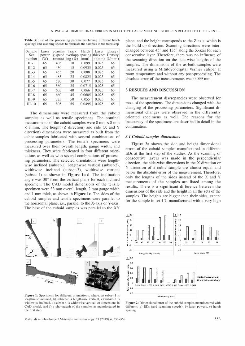
Table 3: List of the processing parameters having different hatchspacings and scanning speeds to fabricate the samples in the third step
SampleSet
number
Laserpower(W)
Scanning speed(mm/s)
Trackoverlapping (%)
Hatchspacing(mm)
Layerthickness (mm)
EnergyDensity(J/mm3)
III-1 65 405 10 0.099 0.025 65III-2 65 430 15 0.0935 0.025 65III-3 65 455 20 0.088 0.025 65III-4 65 485 25 0.0825 0.025 65III-5 65 520 30 0.077 0.025 65III-6 65 560 35 0.0715 0.025 65III-7 65 605 40 0.066 0.025 65III-8 65 660 45 0.0605 0.025 65III-9 65 725 50 0.055 0.025 65
III-10 65 805 55 0.0495 0.025 65
The dimensions were measured from the cuboidsamples as well as tensile specimens. The nominalmeasurements of the cuboid samples were 8 mm × 8 mm× 8 mm. The height (Z direction) and side (X and Ydirection) dimensions were measured as built from thecubic samples fabricated with several combinations ofprocessing parameters. The tensile specimens weremeasured over their overall length, gauge width, andthickness. They were fabricated in four different orien-tations as well as with several combinations of process-ing parameters. The selected orientations were length-wise inclined (subset-1), lengthwise vertical (subset-2),widthwise inclined (subset-3), widthwise vertical(subset-4) as shown in Figure 1a-d. The inclinationangle was 30° from the vertical plane for each inclinedspecimen. The CAD model dimensions of the tensilespecimen were 33 mm overall length, 2 mm gauge widthand 1 mm thick, as shown in Figure 1e. The sides of thecuboid samples and tensile specimens were parallel tothe horizontal plane, i.e., parallel to the X-axis or Y-axis.The base of the cuboid samples was parallel to the XY
plane, and the height corresponds to the Z axis, which isthe build-up direction. Scanning directions were inter-changed between 45° and 135° along the X-axis for eachconsecutive layer. Therefore, there was no influence ofthe scanning direction on the side-wise lengths of thesamples. The dimensions of the as-built samples weremeasured using a Mitutoyo digital Vernier caliper atroom temperature and without any post-processing. Theabsolute error of the measurements was 0.099 mm.
3 RESULTS AND DISCUSSION
The measurement discrepancies were observed formost of the specimens. The dimensions changed with thechanging of the processing parameters. Significant di-mensional changes were observed in the differentlyoriented specimens as well. The reasons for theinaccuracy of the specimens are described in detail in thecontinuation.
3.1 Cuboid samples dimensions
Figure 2a shows the side and height dimensionalerrors of the cuboid samples manufactured in differentEDs at the first step of the studies. As the scanning ofconsecutive layers was made in the perpendiculardirection, the side-wise dimensions in the X direction orY direction of a cubic sample are almost equal andbelow the absolute error of the measurement. Therefore,only the lengths of the sides instead of the X and Ymeasurements of the samples are listed among theresults. There is a significant difference between thedimensions of the side and the height in all the sets of thesamples. The heights are bigger than their sides, exceptfor the sample in set-I-7, manufactured with a very high
S. PAL et al.: DIMENSIONAL ERRORS IN SELECTIVE LASER MELTING PRODUCTS RELATED TO DIFFERENT ...
Materiali in tehnologije / Materials and technology 53 (2019) 4, 551–558 553
Figure 1: Specimens for different orientations, where: a) subset-1 islengthwise inclined, b) subset-2 is lengthwise vertical, c) subset-3 iswidthwise inclined, d) subset-4 is widthwise vertical, e) dimensions inCAD model, and f) a photograph of the samples as manufactured inthe first step.
Figure 2: Dimensional error of the cuboid samples manufactured withdifferent: a) EDs (and scanning speeds), b) laser powers, c) hatchspacing

ED (260 J/mm3). Among the sets, both dimensions, side,and height, slightly increase with a rise of the ED. Thebest side measurement was obtained in cuboid set-I-3manufactured with 65 J/mm3 ED and 600 mm/s scanningspeed. The cuboid set-II-1 has the smallest side error andthe height error is not much different from the lowestheight error.
By combining the cuboid samples from set-I-1 toset-I-6 into three groups containing two consecutivesamples (set-I-1 and set-I-2 belong to group-1, set-I-3and set-I-4 belong to group-2 and so on), it can beobserved that each group has similar results. The oddnumbered sample has a bit lower side-length error thanthe following even-numbered sample in each group andthe heights are also almost equal in both samples in eachgroup. This is due to the ED values and the scanningspeeds (influencing cooling rates) lying in the sameeffective range in each group. The melt-pool volumeoccupies the tiny space in the actioning layer and asmaller space in the preceding layer.8 Except for the lastpreceding layer, the other preceding layers stay at alower temperature because of the low thermal conduc-tivity of the Ti-6Al-4V alloy.1,5 The area of the scannedlayer slightly expands during the action. The increase ofthe ED causes an increase of the temperature at thescanning area that causes a higher melt pool volume aswell as the higher expansion of material that reduces thecrystallinity.18 The reduction of the crystallinity leads toa reduction in the shrinkage. On the other hand, a higherscanning speed causes a higher cooling rate, which leadsto lack of crystallinity time. Therefore, an even sampleshrinks less than the following odd sample.
Shrinkage is not identical along the Z and X or Y di-rections since the product builds up along the Z directionand the scanning works along the X or Y direction alter-nately. The side is affected by the area of the layer to bescanned, whereas its height is affected by the layerthickness. Therefore, it has been observed that theexpansion is significantly higher in the built up (Z)directions compared to the X and Y directions. As theset-I-7 was manufactured with an extremely low scann-ing speed and high ED, it had sufficient time for crys-tallization, which leads to a high shrinkage in the Zdirection and expansion in the X and Y directions.Additionally, at the highest ED, a huge spattering ofmaterial was observed that caused a reduction ofmaterial, which led to the lowering of the height.19,20
During scanning of the starting layer on the supportstructure, the first layer melt-pool volume depends onED, and the higher ED caused a higher melt-poolvolume,19 which occupied the area below the expectedbottom surface of the product. Therefore, rising the EDfrom 39 J/mm3 to 195 J/mm3 caused higher additionaldimensions from the set-I-1 to set-I-2, respectively.
A quite similar dimensional error effect can beobserved in the cuboid samples in the second step as inthe first step, which is illustrated in Figure 2b. Almost
similar dimensional errors were observed in all the setsdue to the same ED employed in all the sets. As theemployed energy and cooling rate provoke the expansionand shrinkage of the material; therefore, the laser powerdoes not have any significant correlation with them.
Figure 2c illustrates the dimensional error of thecuboid samples manufactured in the third step consider-ing different hatch spacing. The results show that thesamples manufactured with a smaller track overlapping(higher hatch spacing) shrunk less because of the shorterscanning time for the entire layer. Thus, the first fewsamples cool down faster, which caused lower crys-tallinity. Increasing the track overlapping (shorter hatchspacing) leads to an increase of the scanning time andreduces the cooling rate. A lower cooling rate allowsmore time for the molecules to arrange in an order,which rises the crystallinity, which in turn causes highershrinkage. As a result, the specimens in set-III-6 (manu-factured with 35 % track overlapping and 560 mm/sscanning speed) shrink optimally and come closer to thedimensions of the CAD file after cooling. A furtherincrease of the track overlapping happens along with thehigher scanning speed, which again reduces the scanningtime and raises the cooling rate. Additionally, highertrack overlapping causes a higher temperature at theoverlapping area, which causes a bigger melt-pool vol-ume at the starting layer. Thus, the dimensions increasefrom the cuboid set-III-7 onwards.
3.1 Tensile specimens’ dimensions fabricated in diffe-rent directions
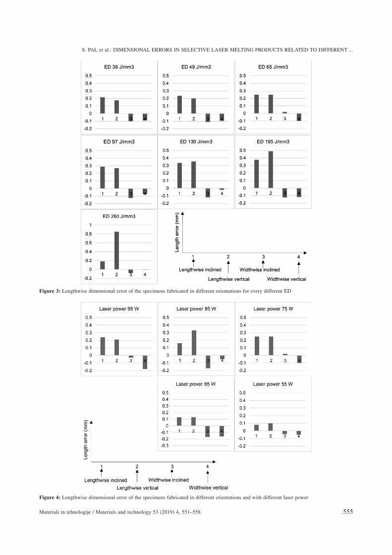
The dimensional variations and phenomena of thecuboid samples are reflected in the tensile specimensmanufactured in different orientations. The lengthwiseinclined and vertically built up specimens exhibit alonger length compared to the widthwise inclined andvertical specimens in all sets of the first step of the study,built up in different EDs. Interestingly, Figure 3 showsthat the lengths of the lengthwise build up specimens(subset-1 and subset-2) for each set are higher than theCAD dimensions and the lengths of the widthwise buildup specimens (subset-3 and subset-4) for each set arelower than the CAD dimensions. Similar variations wereobserved in cuboid samples where the heights (in the Zdirection) are longer than the side (in X or Y direction).Most of the lengthwise build up specimens have a lengthof about 33.25±0.10 mm from set-I-1 to set-I-5, wherehigher EDs performed higher length up to 33.49 mm,where the original CAD length was 33 mm. On the otherhand, widthwise built up specimens shrunk below theiroriginal lengths to about 32.92±0.08 mm. Comparing thehorizontal lengths of both the cuboid samples and thetensile specimens (considering lengthwise only), it canbe seen that a bigger (longer) scanning area produces ahigher shrinkage than a smaller (shorter) area, whichcorresponds to the phenomenon of thermal expansionand is somewhat expected.
S. PAL et al.: DIMENSIONAL ERRORS IN SELECTIVE LASER MELTING PRODUCTS RELATED TO DIFFERENT ...
554 Materiali in tehnologije / Materials and technology 53 (2019) 4, 551–558
S. PAL et al.: DIMENSIONAL ERRORS IN SELECTIVE LASER MELTING PRODUCTS RELATED TO DIFFERENT ...
Materiali in tehnologije / Materials and technology 53 (2019) 4, 551–558 555
Figure 4: Lengthwise dimensional error of the specimens fabricated in different orientations and with different laser power
Figure 3: Lengthwise dimensional error of the specimens fabricated in different orientations for every different ED
The same effect was observed in the second step of
the experiment. Figure 4 demonstrates that the length-
wise built up specimens (subset-1 and subset-2) have a
longer length than the widthwise built up specimens
(subset-3 and subset-4). As previously, the lengthwise
built up specimens are longer and inversely, the width-
wise built up specimens are shorter than the nominal
length.
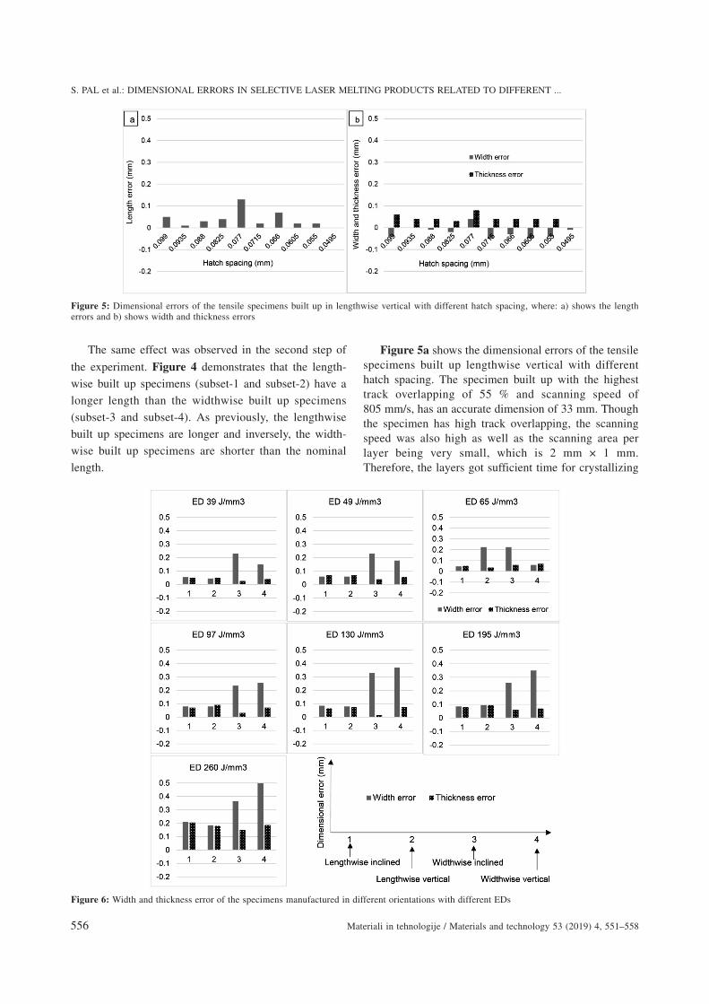
Figure 5a shows the dimensional errors of the tensilespecimens built up lengthwise vertical with differenthatch spacing. The specimen built up with the highesttrack overlapping of 55 % and scanning speed of805 mm/s, has an accurate dimension of 33 mm. Thoughthe specimen has high track overlapping, the scanningspeed was also high as well as the scanning area perlayer being very small, which is 2 mm × 1 mm.Therefore, the layers got sufficient time for crystallizing
S. PAL et al.: DIMENSIONAL ERRORS IN SELECTIVE LASER MELTING PRODUCTS RELATED TO DIFFERENT ...
556 Materiali in tehnologije / Materials and technology 53 (2019) 4, 551–558
Figure 5: Dimensional errors of the tensile specimens built up in lengthwise vertical with different hatch spacing, where: a) shows the lengtherrors and b) shows width and thickness errors
Figure 6: Width and thickness error of the specimens manufactured in different orientations with different EDs

and shrinking to achieve the desired size in the Zdirection.
The previous dimensional consequences show thatthe Z direction has a higher dimension than the X and Ydirections. The width of a specimen is perpendicular toits length, which means the specimens oriented in the Zdirection have the width in the Y direction and thespecimens oriented in Y direction have their widths inthe Z direction. Figure 6 shows that the results aresimilar to the previous results, which means the Z lengthis longer than the Y length. Hence, the widths of thespecimens subset-3 and subset-4 have a higher valuethan the specimens in subset-1 and subset-2 in the firststep.
Certainly, Figure 7 proves that widths of the speci-mens built up in different orientations in the second sethave similar dimensions. Subset-3 and Subset-4 havehigher widths than subset-1 and subset-2.
From Figure 5b it is clear that the tensile specimennumber 10 in the third step has the desired dimensionswith the lowest hatch spacing (0.0495 mm), i.e., thehighest track overlapping (55 %). Therefore, slightlydifferent results are observed between the cuboid sam-ples and the tensile specimens. The optimally dimen-sioned cube was produced in the set-III-6, whereas theoptimum dimensioned tensile specimen was manufac-tured lengthwise vertically in the set-III-10.
4 CONCLUSIONS
This study has reported the changes and errors in thedimensions of Ti-6Al-4V alloy products fabricated withdifferent EDs, scanning speeds, laser powers, hatchspacings, and building orientations. The majority of theresults show that the length in the Z direction is higherthan the X or Y direction as well as the errors are mostlypositive in the Z directions, whereas they are negative inthe X and Y directions. The dimensions are significantlyinfluenced by the input energy and the cooling rateduring fusion and amalgamation. These thermodynamicand physical mechanisms directly depend on the ED andthe scanning speed. The laser power has no influence ifthe ED remains constant. Eventually, the desired dimen-sion was achieved in the cuboid sample set-III-6. Thetensile specimen built up lengthwise vertical in set-III-10showed the desired dimensions as in the CAD model.
Acknowledgements
The authors are thankful to the Technical Universityof Kosice and Orthotip for their continuous support andcooperation in the manufacturing of the samples. Theauthors are grateful to the University of Maribor forproviding metallurgical equipment and technical support.The authors are obliged to the Erasmus MundusEUPHRATES project for providing financial support.
S. PAL et al.: DIMENSIONAL ERRORS IN SELECTIVE LASER MELTING PRODUCTS RELATED TO DIFFERENT ...
Materiali in tehnologije / Materials and technology 53 (2019) 4, 551–558 557
Figure 7: Width and thickness error of the specimens manufactured in different orientations with different laser powers

6 REFERENCES1 J. Yang, H. Yang, H. Yu, Z. Wang, H. Wang, X. Zeng, A novel
approach to in-situ fabricate Ti-6Al-4V alloy with graded micro-structure and property by selective laser melting, Mater Lett., 215(2018), 246-249, doi:10.1016/j.matlet.2017.12.098
2 M. Vaezi, H. Seitz, S. Yang, A review on 3D micro-additivemanufacturing technologies, Int J Adv Manuf Technol., 67 (2013)5–8, 1721–1754, doi:10.1007/s00170-012-4605-2
3 S. A. Adekanye, R. M. Mahamood, E. T. Akinlabi, M. G.Owolabi,Additive manufacturing: the future of manufacturing, Mater Tehnol.,51 (2017) 5, 709–715, doi:10.17222/mit.2016.261
4 L. Thijs, F. Verhaeghe, T. Craeghs, J. V. Humbeeck, J. P. Kruth. Astudy of the microstructural evolution during selective laser meltingof Ti-6Al-4V, Acta Mater., 58 (2010) (9), 3303–3312,doi:10.1016/j.actamat.2010.02.004
5 H. Shipley, D. McDonnell, M. Culleton, R. Coull, R. Lupoi, G.O’Donnell, D. Trimble, Optimisation of process parameters toaddress fundamental challenges during selective laser melting ofTi-6Al-4V: A review, Int J Mach Tools Manuf., 128 (2018) 1–20,doi:10.1016/j.ijmachtools.2018.01.003
6 S. Barui, S. Chatterjee, S. Mandal, A. Kumar, B. Basu, Microstruc-ture and compression properties of 3D powder printed Ti-6Al-4Vscaffolds with designed porosity: Experimental and computationalanalysis, Mater Sci Eng C, 70 (2017), 812–823, doi:10.1016/j.msec.2016.09.040
7 J. Song, W. Wu, L. Zhang, B. He, L. Lu, X. Ni, Q. Long, G. Zhu,Role of scanning strategy on residual stress distribution in Ti-6Al-4Valloy prepared by selective laser melting, Optik (Stuttg), 170 (2018),342–352, doi:10.1016/j.ijleo.2018.05.128
8 M. Masoomi, S. M. Thompson, N. Shamsaei, Laser powder bedfusion of Ti-6Al-4V parts: Thermal modeling and mechanicalimplications, Int J Mach Tools Manuf, 118-119 (2017) 73–90,doi:10.1016/j.ijmachtools.2017.04.007
9 S. Pal, I. Drstvensek, Physical behaviors of materials in selectivelaser melting process, DAAAM Int Sci B., Vienna 2018, 239–256,doi:10.2507/daaam.scibook.2018.21
10 H. Yu, J. Yang, J. Yin, Z. Wang, X. Zeng, Comparison on mechanicalanisotropies of selective laser melted Ti-6Al-4V alloy and 304stainless steel, Mater Sci Eng A, 695 (2017) 92–100, doi:10.1016/j.msea.2017.04.031
11 U. Kostevsek, T. Brajlih, J. Balic, @. Kadivnik, I. Drstvensek, Deve-lopment of productivity estimation model for mass-customized
production by selective laser melting, Rapid Prototyp J, 24 (2018) 3,670–676, doi:10.1108/RPJ-06-2017-0120
12 T. Brajlih, B. Valentan, J. Balic, I. Drstvensek, Speed and accuracyevaluation of additive manufacturing machines, Rapid Prototyp J, 17(2011) 1, 64–75, doi:10.1108/13552541111098644
13 S. Y. Chen, J. C. Huang, C. T. Pan, C. H. Lin, T. L. Yang, Y. S.Huang, C. H. Ou, L. Y. Chen, D. Y. Lin, H. K. Lin, T. H. Li, J. S. C.Jang, C. C. Yang, Microstructure and mechanical properties ofopen-cell porous Ti-6Al-4V fabricated by selective laser melting, JAlloys Compd., 713 (2017), 248–254, doi:10.1016/j.jallcom.2017.04.190
14 R. Wauthle, J. Van Der Stok, S. A. Yavari, J. V. Humbeeck, J. P.Kruth, A. A. Zadpoor, H. Weinans, M. Mulier, J. Schrooten, Additiv-ely manufactured porous tantalum implants, Acta Biomater., 14(2015), 217–225, doi:10.1016/j.actbio.2014.12.003
15 N. T. Aboulkhair, I. Maskery, C. Tuck, I. Ashcroft, N. M. Everitt, Onthe formation of AlSi10Mg single tracks and layers in selective lasermelting: Microstructure and nano-mechanical properties, J MaterProcess Technol., 230 (2016), 88–98, doi:10.1016/j.jmatprotec.2015.11.016
16 B. Nie, H. Huang, S. Bai, J. Liu, Femtosecond laser melting andresolidifying of high-temperature powder materials, Appl Phys AMater Sci Process, 118 (2014) 1, 37–41, doi:10.1007/s00339-014-8897-y
17 S. Pal, H. R. Tiyyagura, I. Drstven{ek, C. S. Kumar, The effect ofpost-processing and machining process parameters on properties ofstainless steel PH1 product produced by direct metal laser sintering,Procedia Eng., 149 (2016), 359–365, doi:10.1016/j.proeng.2016.06.679.
18 T. H. C. Childs, A. E. Tontowi, Selective laser sintering of a crys-talline and a glass-filled crystalline polymer: Experiments andsimulations, Proc Inst Mech Eng, Part B: J Eng Manuf., 215 (2001)11, 1481–1495, doi:10.1243/0954405011519330
19 S. Pal, G. Lojen, V. Kokol, I. Drstvensek, Evolution of metallurgicalproperties of Ti-6Al-4V alloy fabricated in different energy densitiesin the Selective Laser Melting technique, J Manuf Process., 35(2018), 538–546, doi:10.1016/j.jmapro.2018.09.012
20 S. Pal, N. Gubeljak, R. Hudak, G. Lojen, V. Rajtukova, J. Predan, V.Kokol, I. Drstvensek, Tensile properties of selective laser meltingproducts affected by building orientation and energy density, MaterSci Eng A, 743 (2018), 637–647, doi:10.1016/J.MSEA.2018.11.130
S. PAL et al.: DIMENSIONAL ERRORS IN SELECTIVE LASER MELTING PRODUCTS RELATED TO DIFFERENT ...
558 Materiali in tehnologije / Materials and technology 53 (2019) 4, 551–558
Related Documents