Digital Systems © Korea Univ. of Tech. & Edu. Dept. of Info. & Comm. Chap. 1 Introductory Concepts 1-1 Digital Systems: Principles and Applications 12th Edition Tocci Widmer Moss 정보통신공학과 이 명의 (A-405) [email protected]

Welcome message from author
This document is posted to help you gain knowledge. Please leave a comment to let me know what you think about it! Share it to your friends and learn new things together.
Transcript
Digital Systems© Korea Univ. of Tech. & Edu.
Dept. of Info. & Comm.Chap. 1 Introductory Concepts
1-1
Digital Systems: Principles and Applications
12th Edition
Tocci Widmer Moss
정보통신공학과 이 명의 (A-405)[email protected]
Digital Systems© Korea Univ. of Tech. & Edu.
Dept. of Info. & Comm.Chap. 1 Introductory Concepts
1-2Class Overview
Chapter Organization» This book can be used either in a one-term course or in a two-
term sequence» In a one-term course, limits on available class hours might
require omitting some topics.» The choice of deletions will depend on factors such as program
or course objectives and student background.» Sections in each chapter that deal with troubleshooting, PLDs,
HDLs, or microcomputer applications can be deferred to an advanced course.
» But our class deals with all section from chapter 1 to chapter 8 in a one-term course.
» Our objective of this class is to study the first course in Digital Circuit (Digital number systems, Logic gates/operations, Combinational circuit design, Sequential circuit design, IC families/interfaces, HDLs, and Troubleshootings)

Digital Systems© Korea Univ. of Tech. & Edu.
Dept. of Info. & Comm.Chap. 1 Introductory Concepts
1-3Class Overview
First Course in Digital Circuit (Objectives)» 1. Digital number systems : Chap. 1 and 2» 2. Logic gates/operations : Chap. 3» 3. Combinational circuit design : Chap. 4 and 6» 4. Sequential circuit design : Chap. 5 and 7» 5. IC families/interfaces : Chap 8» 6. HDL : Chap. 3, 4, 5, 6, and 7 » 7. Some troubleshooting examples at the end of chapter
Homework:» Solve the odd or even number of problems according to the
current year» Due at the beginning of the mid(first) and final(second)
exam.

Digital Systems© Korea Univ. of Tech. & Edu.
Dept. of Info. & Comm.Chap. 1 Introductory Concepts
1-4Class Overview
Lecture Notes : http://microcom.kut.ac.kr
Grade:» Homework(20%)» Mid/Final Exam(each 30%)» Class Participation(20%)
Textbook:
Digital Systems© Korea Univ. of Tech. & Edu.
Dept. of Info. & Comm.Chap. 1 Introductory Concepts
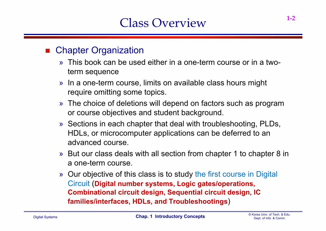
1-58 Student Types
Insecure: 25 % Silent: 20 % Independent: 12 % Friendly: 11 % Obedient: 10 % Heroic: 9 % Critic: 9 % Unmotivated: 4 %
- Michigan State University

Digital Systems© Korea Univ. of Tech. & Edu.
Dept. of Info. & Comm.Chap. 1 Introductory Concepts
1-6Digital Systems
Digital devices
Analog devices
Major difference between analog and digital» analog = continuous» digital = discrete
Digital Systems© Korea Univ. of Tech. & Edu.
Dept. of Info. & Comm.Chap. 1 Introductory Concepts
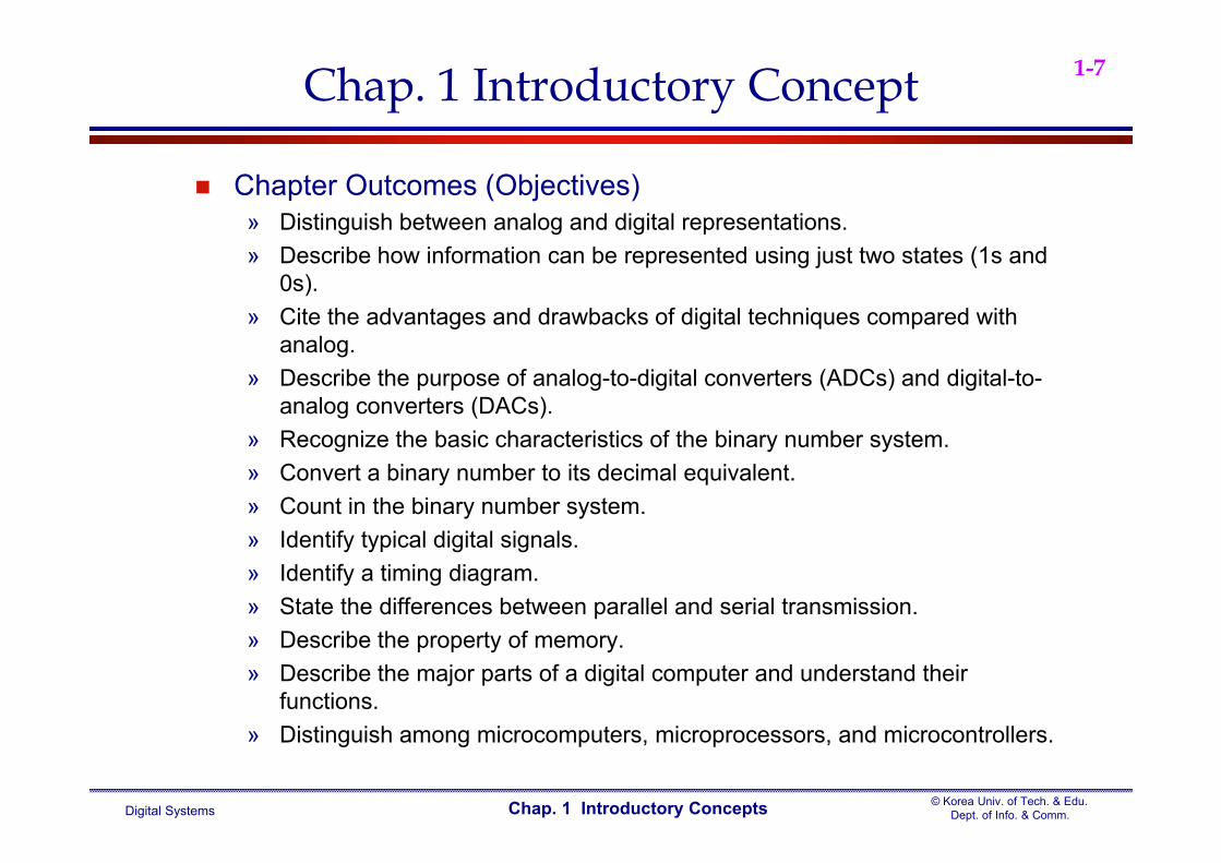
1-7Chap. 1 Introductory Concept
Chapter Outcomes (Objectives)» Distinguish between analog and digital representations.» Describe how information can be represented using just two states (1s and
0s).» Cite the advantages and drawbacks of digital techniques compared with
analog.» Describe the purpose of analog-to-digital converters (ADCs) and digital-to-
analog converters (DACs).» Recognize the basic characteristics of the binary number system.» Convert a binary number to its decimal equivalent.» Count in the binary number system.» Identify typical digital signals.» Identify a timing diagram.» State the differences between parallel and serial transmission.» Describe the property of memory.» Describe the major parts of a digital computer and understand their
functions.» Distinguish among microcomputers, microprocessors, and microcontrollers.

Digital Systems© Korea Univ. of Tech. & Edu.
Dept. of Info. & Comm.Chap. 1 Introductory Concepts
1-81-1. Introduction to Digital 1’s and 0’s
Digital systems deal with things that are in one of two distinct states. The easiest example is anything that is either on or off.
» On/off switch is a single push button : Fig. 1-1 the ubiquitous on/off symbol
The numerical digits used to describe the two states » Numeric digits 0 and 1 to represent the two states off and on
There are only two digits, we call them binary digits, or bits The digital systems are a bunch of 1s and 0s and pretty accurate. When we organize groups of numeric digits,
» We can create number systems and number systems are very powerful ways to represent things.
Digital Systems© Korea Univ. of Tech. & Edu.
Dept. of Info. & Comm.Chap. 1 Introductory Concepts
1-91-1. Introduction to Digital 1’s and 0’s
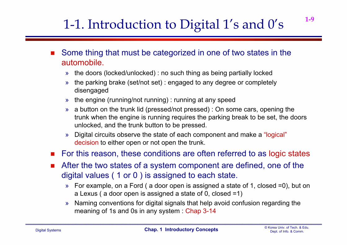
Some thing that must be categorized in one of two states in the automobile.
» the doors (locked/unlocked) : no such thing as being partially locked» the parking brake (set/not set) : engaged to any degree or completely
disengaged» the engine (running/not running) : running at any speed» a button on the trunk lid (pressed/not pressed) : On some cars, opening the
trunk when the engine is running requires the parking break to be set, the doors unlocked, and the trunk button to be pressed.
» Digital circuits observe the state of each component and make a “logical” decision to either open or not open the trunk.
For this reason, these conditions are often referred to as logic states After the two states of a system component are defined, one of the
digital values ( 1 or 0 ) is assigned to each state.» For example, on a Ford ( a door open is assigned a state of 1, closed =0), but on
a Lexus ( a door open is assigned a state of 0, closed =1)» Naming conventions for digital signals that help avoid confusion regarding the
meaning of 1s and 0s in any system : Chap 3-14
Digital Systems© Korea Univ. of Tech. & Edu.
Dept. of Info. & Comm.Chap. 1 Introductory Concepts
1-101-1. Introduction to Digital 1’s and 0’s
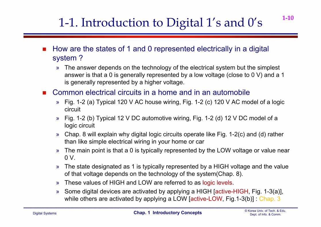
How are the states of 1 and 0 represented electrically in a digital system ?
» The answer depends on the technology of the electrical system but the simplest answer is that a 0 is generally represented by a low voltage (close to 0 V) and a 1 is generally represented by a higher voltage.
Common electrical circuits in a home and in an automobile» Fig. 1-2 (a) Typical 120 V AC house wiring, Fig. 1-2 (c) 120 V AC model of a logic
circuit» Fig. 1-2 (b) Typical 12 V DC automotive wiring, Fig. 1-2 (d) 12 V DC model of a
logic circuit» Chap. 8 will explain why digital logic circuits operate like Fig. 1-2(c) and (d) rather
than like simple electrical wiring in your home or car» The main point is that a 0 is typically represented by the LOW voltage or value near
0 V. » The state designated as 1 is typically represented by a HIGH voltage and the value
of that voltage depends on the technology of the system(Chap. 8).» These values of HIGH and LOW are referred to as logic levels.» Some digital devices are activated by applying a HIGH [active-HIGH, Fig. 1-3(a)],
while others are activated by applying a LOW [active-LOW, Fig.1-3(b)] : Chap. 3
Digital Systems© Korea Univ. of Tech. & Edu.
Dept. of Info. & Comm.Chap. 1 Introductory Concepts
1-111-1. Introduction to Digital 1’s and 0’s
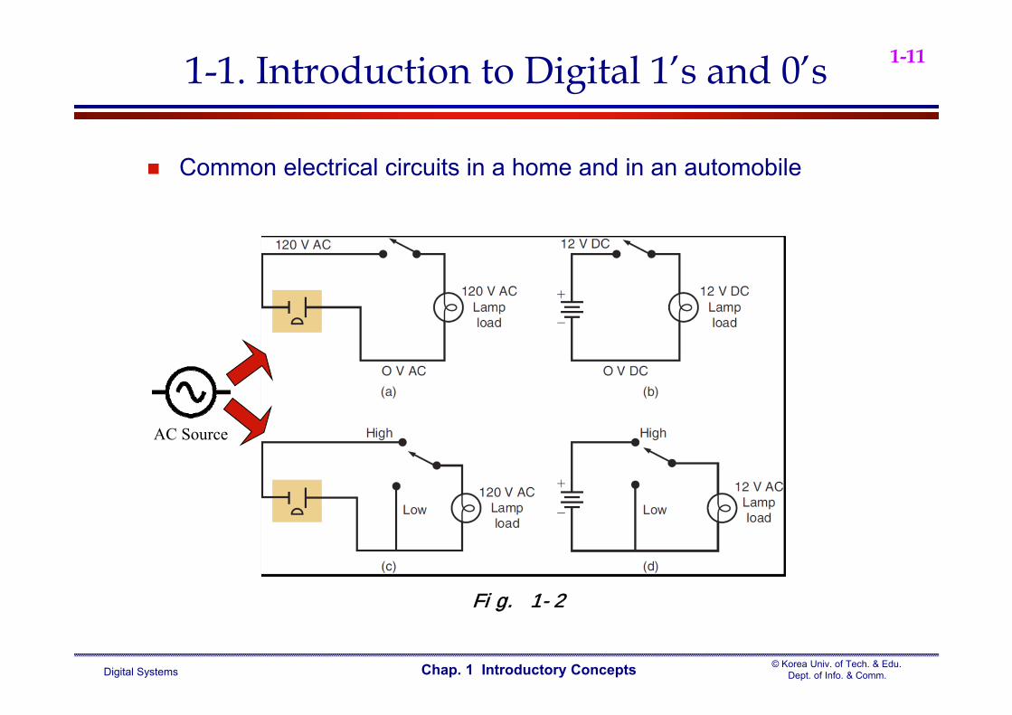
Common electrical circuits in a home and in an automobile
Fig. 1-2
AC Source
Digital Systems© Korea Univ. of Tech. & Edu.
Dept. of Info. & Comm.Chap. 1 Introductory Concepts
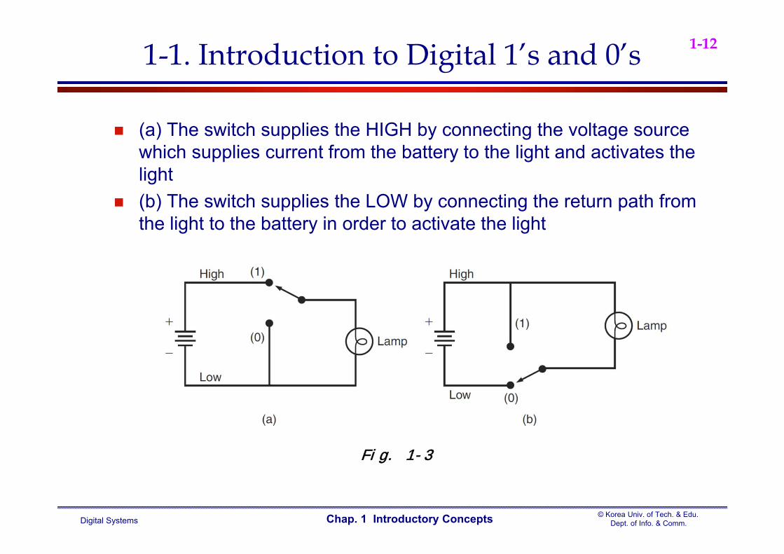
1-121-1. Introduction to Digital 1’s and 0’s
(a) The switch supplies the HIGH by connecting the voltage source which supplies current from the battery to the light and activates the light
(b) The switch supplies the LOW by connecting the return path from the light to the battery in order to activate the light
Fig. 1-3
Digital Systems© Korea Univ. of Tech. & Edu.
Dept. of Info. & Comm.Chap. 1 Introductory Concepts
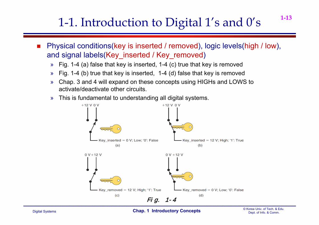
1-131-1. Introduction to Digital 1’s and 0’s
Physical conditions(key is inserted / removed), logic levels(high / low), and signal labels(Key_inserted / Key_removed)
» Fig. 1-4 (a) false that key is inserted, 1-4 (c) true that key is removed» Fig. 1-4 (b) true that key is inserted, 1-4 (d) false that key is removed» Chap. 3 and 4 will expand on these concepts using HIGHs and LOWS to
activate/deactivate other circuits.» This is fundamental to understanding all digital systems.
Fig. 1-4
Digital Systems© Korea Univ. of Tech. & Edu.
Dept. of Info. & Comm.Chap. 1 Introductory Concepts
1-141-1. Introduction to Digital 1’s and 0’s
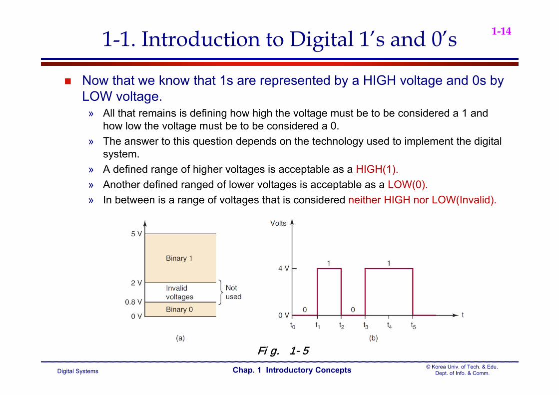
Now that we know that 1s are represented by a HIGH voltage and 0s by LOW voltage.
» All that remains is defining how high the voltage must be to be considered a 1 and how low the voltage must be to be considered a 0.
» The answer to this question depends on the technology used to implement the digital system.
» A defined range of higher voltages is acceptable as a HIGH(1). » Another defined ranged of lower voltages is acceptable as a LOW(0).» In between is a range of voltages that is considered neither HIGH nor LOW(Invalid).
Fig. 1-5
Digital Systems© Korea Univ. of Tech. & Edu.
Dept. of Info. & Comm.Chap. 1 Introductory Concepts
1-151-1. Introduction to Digital 1’s and 0’s
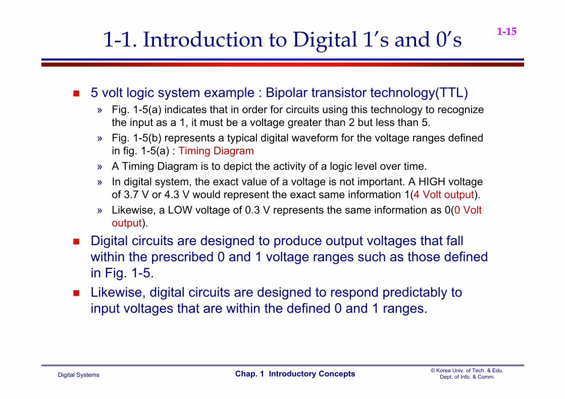
5 volt logic system example : Bipolar transistor technology(TTL)» Fig. 1-5(a) indicates that in order for circuits using this technology to recognize
the input as a 1, it must be a voltage greater than 2 but less than 5.» Fig. 1-5(b) represents a typical digital waveform for the voltage ranges defined
in fig. 1-5(a) : Timing Diagram» A Timing Diagram is to depict the activity of a logic level over time.» In digital system, the exact value of a voltage is not important. A HIGH voltage
of 3.7 V or 4.3 V would represent the exact same information 1(4 Volt output). » Likewise, a LOW voltage of 0.3 V represents the same information as 0(0 Volt
output).
Digital circuits are designed to produce output voltages that fall within the prescribed 0 and 1 voltage ranges such as those defined in Fig. 1-5.
Likewise, digital circuits are designed to respond predictably to input voltages that are within the defined 0 and 1 ranges.

Digital Systems© Korea Univ. of Tech. & Edu.
Dept. of Info. & Comm.Chap. 1 Introductory Concepts
1-161-1. Introduction to Digital 1’s and 0’s
A digital circuit responds to an input’s binary level ( 0 or 1 ) and not to its actual voltage : Fig. 1-6
Case I and Case II have the same output voltage (Vo) for the HIGH and LOW( 4 V or 0 V), while differing in their input voltage(Vi).
Fig. 1-6
Digital Systems© Korea Univ. of Tech. & Edu.
Dept. of Info. & Comm.Chap. 1 Introductory Concepts
1-171-1. Introduction to Digital 1’s and 0’s
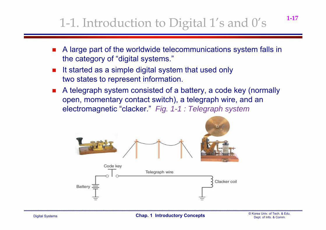
A large part of the worldwide telecommunications system falls in the category of “digital systems.”
It started as a simple digital system that used onlytwo states to represent information.
A telegraph system consisted of a battery, a code key (normally open, momentary contact switch), a telegraph wire, and an electromagnetic “clacker.” Fig. 1-1 : Telegraph system
Digital Systems© Korea Univ. of Tech. & Edu.
Dept. of Info. & Comm.Chap. 1 Introductory Concepts
1-181-1. Introduction to Digital 1’s and 0’s
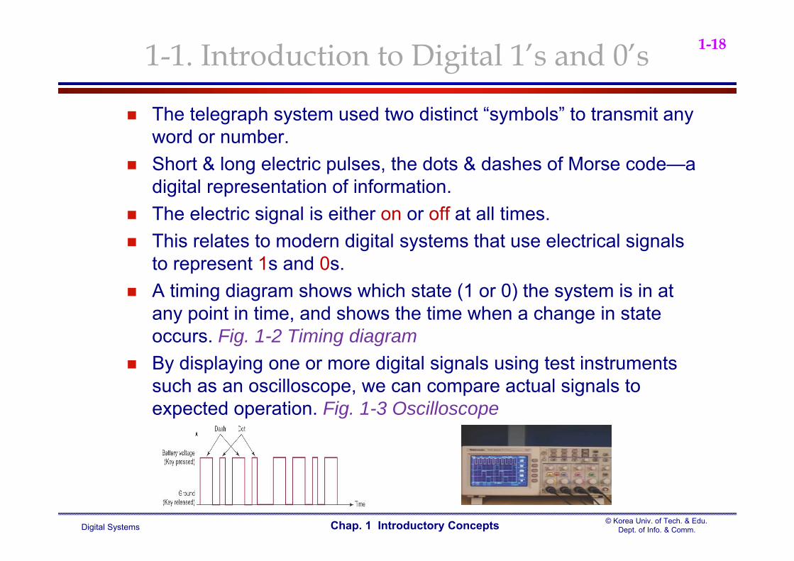
The telegraph system used two distinct “symbols” to transmit any word or number.
Short & long electric pulses, the dots & dashes of Morse code—a digital representation of information.
The electric signal is either on or off at all times. This relates to modern digital systems that use electrical signals
to represent 1s and 0s. A timing diagram shows which state (1 or 0) the system is in at
any point in time, and shows the time when a change in state occurs. Fig. 1-2 Timing diagram
By displaying one or more digital signals using test instruments such as an oscilloscope, we can compare actual signals to expected operation. Fig. 1-3 Oscilloscope
Digital Systems© Korea Univ. of Tech. & Edu.
Dept. of Info. & Comm.Chap. 1 Introductory Concepts
1-19
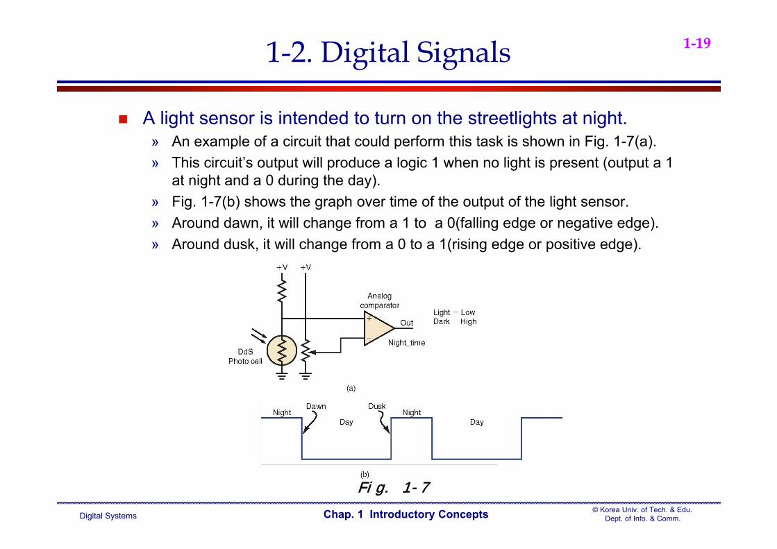
A light sensor is intended to turn on the streetlights at night.» An example of a circuit that could perform this task is shown in Fig. 1-7(a).» This circuit’s output will produce a logic 1 when no light is present (output a 1
at night and a 0 during the day).» Fig. 1-7(b) shows the graph over time of the output of the light sensor.» Around dawn, it will change from a 1 to a 0(falling edge or negative edge).» Around dusk, it will change from a 0 to a 1(rising edge or positive edge).
1-2. Digital Signals
Fig. 1-7
Digital Systems© Korea Univ. of Tech. & Edu.
Dept. of Info. & Comm.Chap. 1 Introductory Concepts
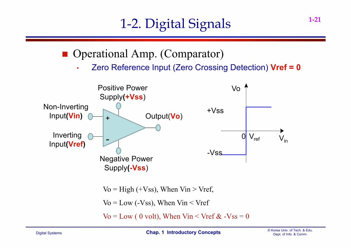
1-20
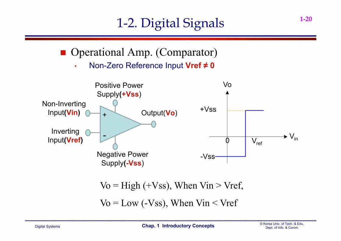
Non-Inverting Input(Vin) Output(Vo)
Inverting Input(Vref)
Positive Power Supply(+Vss)
Negative Power Supply(-Vss)
-
+
1-2. Digital Signals
Vo
Vin
+Vss
-Vss
Vref0
Vo = High (+Vss), When Vin > Vref,
Vo = Low (-Vss), When Vin < Vref
Operational Amp. (Comparator)• Non-Zero Reference Input Vref ≠ 0
Digital Systems© Korea Univ. of Tech. & Edu.
Dept. of Info. & Comm.Chap. 1 Introductory Concepts
1-21
Non-Inverting Input(Vin) Output(Vo)
Inverting Input(Vref)
Positive Power Supply(+Vss)
Negative Power Supply(-Vss)
-
+
1-2. Digital Signals
Vo
Vin
+Vss
-Vss
Vref0
Vo = High (+Vss), When Vin > Vref,
Vo = Low (-Vss), When Vin < Vref
Vo = Low ( 0 volt), When Vin < Vref & -Vss = 0
Operational Amp. (Comparator)• Zero Reference Input (Zero Crossing Detection) Vref = 0

Digital Systems© Korea Univ. of Tech. & Edu.
Dept. of Info. & Comm.Chap. 1 Introductory Concepts
1-221-2. Digital Signals
Photo Cell = Photoresistor = Photoconductive Cell» CdS cells are made of Cadmium-Sulfide» Light-dependent resistor» Resistance is inversely dependent on the amount of light

Digital Systems© Korea Univ. of Tech. & Edu.
Dept. of Info. & Comm.Chap. 1 Introductory Concepts
1-231-2. Digital Signals
Need for Timing» Timing diagrams show the relationship, over time, between many digital
“signals”.» The block diagram in Fig. 1-8(a) detects the ‘edge’ at dawn, waits 10
minutes, and then turns off the streetlamp.» Fig. 1-8(b) is a timing diagram which shows the input to the circuit as well as
the output(relationship between the two signals).» The curvy arrows are used to indicate the cause-and-effect relationship
between input and output signals.
Fig. 1-8
Digital Systems© Korea Univ. of Tech. & Edu.
Dept. of Info. & Comm.Chap. 1 Introductory Concepts
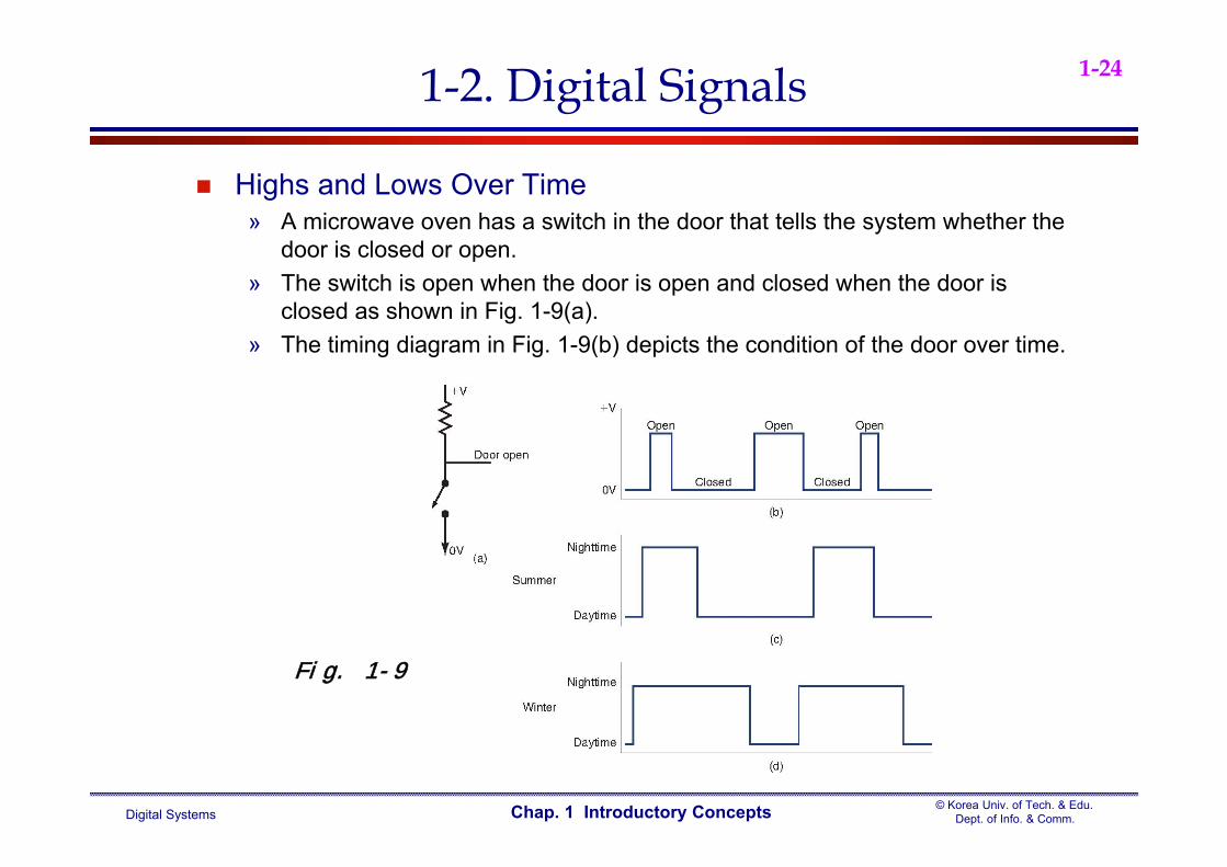
1-241-2. Digital Signals
Highs and Lows Over Time» A microwave oven has a switch in the door that tells the system whether the
door is closed or open.» The switch is open when the door is open and closed when the door is
closed as shown in Fig. 1-9(a).» The timing diagram in Fig. 1-9(b) depicts the condition of the door over time.
Fig. 1-9
Digital Systems© Korea Univ. of Tech. & Edu.
Dept. of Info. & Comm.Chap. 1 Introductory Concepts
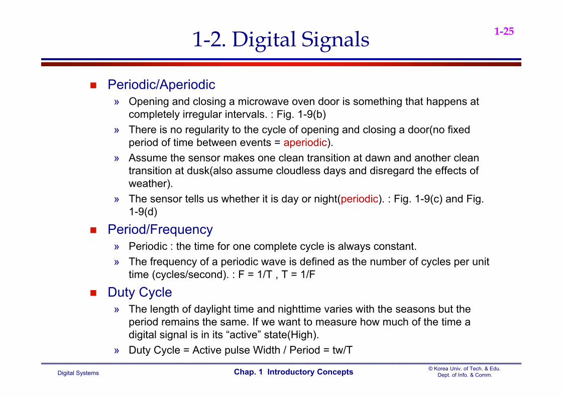
1-251-2. Digital Signals
Periodic/Aperiodic» Opening and closing a microwave oven door is something that happens at
completely irregular intervals. : Fig. 1-9(b)» There is no regularity to the cycle of opening and closing a door(no fixed
period of time between events = aperiodic).» Assume the sensor makes one clean transition at dawn and another clean
transition at dusk(also assume cloudless days and disregard the effects of weather).
» The sensor tells us whether it is day or night(periodic). : Fig. 1-9(c) and Fig. 1-9(d)
Period/Frequency» Periodic : the time for one complete cycle is always constant.» The frequency of a periodic wave is defined as the number of cycles per unit
time (cycles/second). : F = 1/T , T = 1/F
Duty Cycle» The length of daylight time and nighttime varies with the seasons but the
period remains the same. If we want to measure how much of the time a digital signal is in its “active” state(High).
» Duty Cycle = Active pulse Width / Period = tw/T
Digital Systems© Korea Univ. of Tech. & Edu.
Dept. of Info. & Comm.Chap. 1 Introductory Concepts
1-261-2. Digital Signals
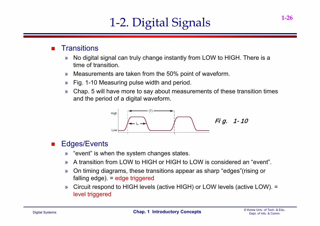
Transitions» No digital signal can truly change instantly from LOW to HIGH. There is a
time of transition.» Measurements are taken from the 50% point of waveform.» Fig. 1-10 Measuring pulse width and period.» Chap. 5 will have more to say about measurements of these transition times
and the period of a digital waveform.
Edges/Events» “event” is when the system changes states.» A transition from LOW to HIGH or HIGH to LOW is considered an “event”.» On timing diagrams, these transitions appear as sharp “edges”(rising or
falling edge). = edge triggered» Circuit respond to HIGH levels (active HIGH) or LOW levels (active LOW). =
level triggered
Fig. 1-10
Digital Systems© Korea Univ. of Tech. & Edu.
Dept. of Info. & Comm.Chap. 1 Introductory Concepts
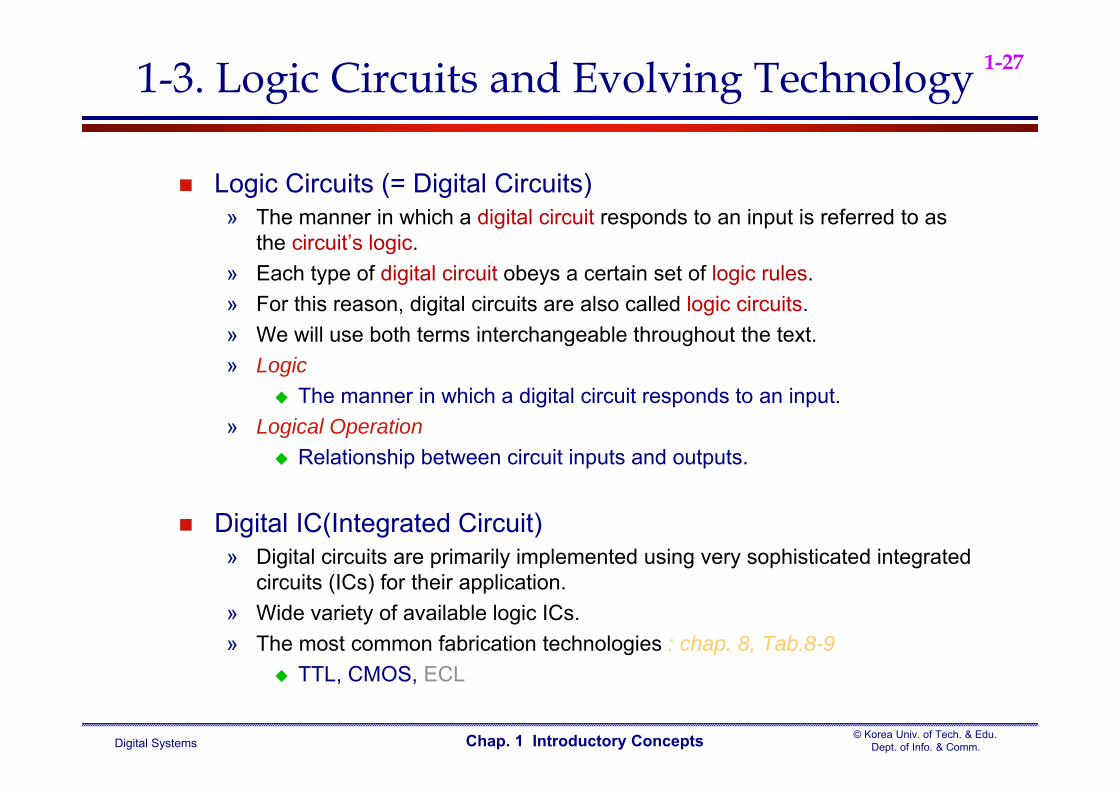
1-271-3. Logic Circuits and Evolving Technology
Logic Circuits (= Digital Circuits)» The manner in which a digital circuit responds to an input is referred to as
the circuit’s logic.» Each type of digital circuit obeys a certain set of logic rules.» For this reason, digital circuits are also called logic circuits.» We will use both terms interchangeable throughout the text.» Logic
The manner in which a digital circuit responds to an input. » Logical Operation
Relationship between circuit inputs and outputs.
Digital IC(Integrated Circuit)» Digital circuits are primarily implemented using very sophisticated integrated
circuits (ICs) for their application.» Wide variety of available logic ICs.» The most common fabrication technologies : chap. 8, Tab.8-9
TTL, CMOS, ECL
Digital Systems© Korea Univ. of Tech. & Edu.
Dept. of Info. & Comm.Chap. 1 Introductory Concepts
1-281-4. Numerical Representations
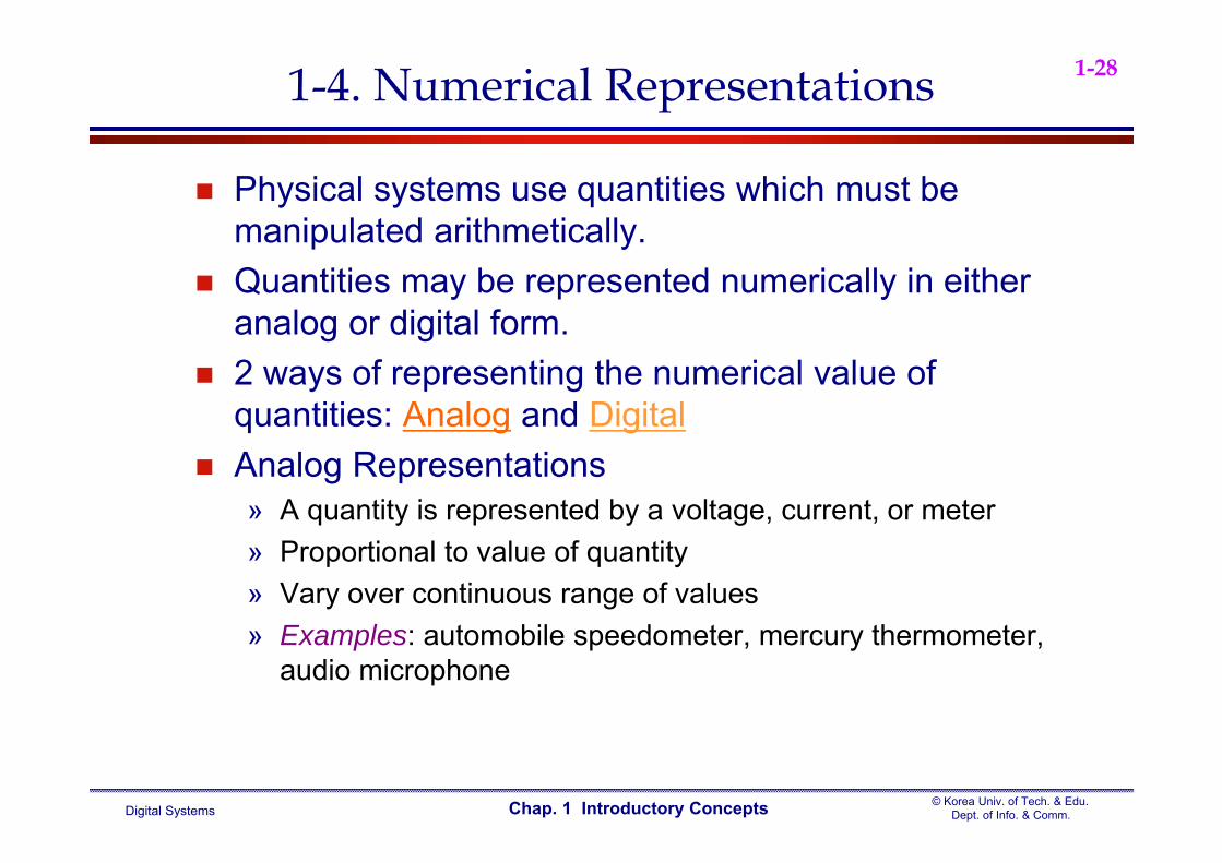
Physical systems use quantities which must be manipulated arithmetically.
Quantities may be represented numerically in either analog or digital form.
2 ways of representing the numerical value of quantities: Analog and Digital
Analog Representations» A quantity is represented by a voltage, current, or meter» Proportional to value of quantity » Vary over continuous range of values» Examples: automobile speedometer, mercury thermometer,
audio microphone

Digital Systems© Korea Univ. of Tech. & Edu.
Dept. of Info. & Comm.Chap. 1 Introductory Concepts
1-291-4. Numerical Representations
In 1875, Alexander Graham Bell figured out how to change his voice into a continuously variable electrical signal, send it through a wire, and change it back to sound energy at the other end.
Today, the device that converts sound energy to an analog voltage signal is known as a microphone
Audio wave
Digital Systems© Korea Univ. of Tech. & Edu.
Dept. of Info. & Comm.Chap. 1 Introductory Concepts
1-301-4 Numerical Representations
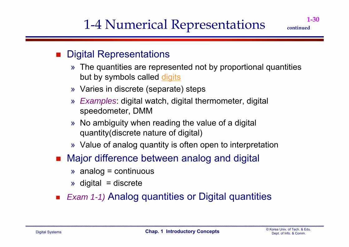
Digital Representations» The quantities are represented not by proportional quantities
but by symbols called digits» Varies in discrete (separate) steps» Examples: digital watch, digital thermometer, digital
speedometer, DMM» No ambiguity when reading the value of a digital
quantity(discrete nature of digital)» Value of analog quantity is often open to interpretation
Major difference between analog and digital» analog = continuous» digital = discrete
Exam 1-1) Analog quantities or Digital quantities
continued

Digital Systems© Korea Univ. of Tech. & Edu.
Dept. of Info. & Comm.Chap. 1 Introductory Concepts
1-31
Digital system» Manipulate digital information» Examples: Digital computers/calculators, Digital audio/video
equipment, Telephone system Analog system
» Manipulate analog information» Example: Audio amplifier, Magnetic tape recorder/playback
equipment, Light dimmer switch Advantages of Digital Techniques
» Easier to design» Information storage is easy» Accuracy and precision are easier to maintain» Operation can be programmed» Immunity to effects of noise» Easy fabricated on integrated circuit (IC) chips
1-5. Digital and Analog Systems continued
Digital Systems© Korea Univ. of Tech. & Edu.
Dept. of Info. & Comm.Chap. 1 Introductory Concepts
1-32
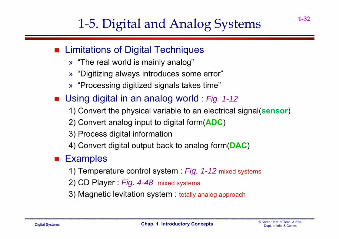
Limitations of Digital Techniques» “The real world is mainly analog”» “Digitizing always introduces some error”» “Processing digitized signals takes time”
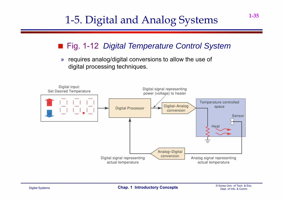
Using digital in an analog world : Fig. 1-121) Convert the physical variable to an electrical signal(sensor)2) Convert analog input to digital form(ADC)3) Process digital information4) Convert digital output back to analog form(DAC)
Examples1) Temperature control system : Fig. 1-12 mixed systems
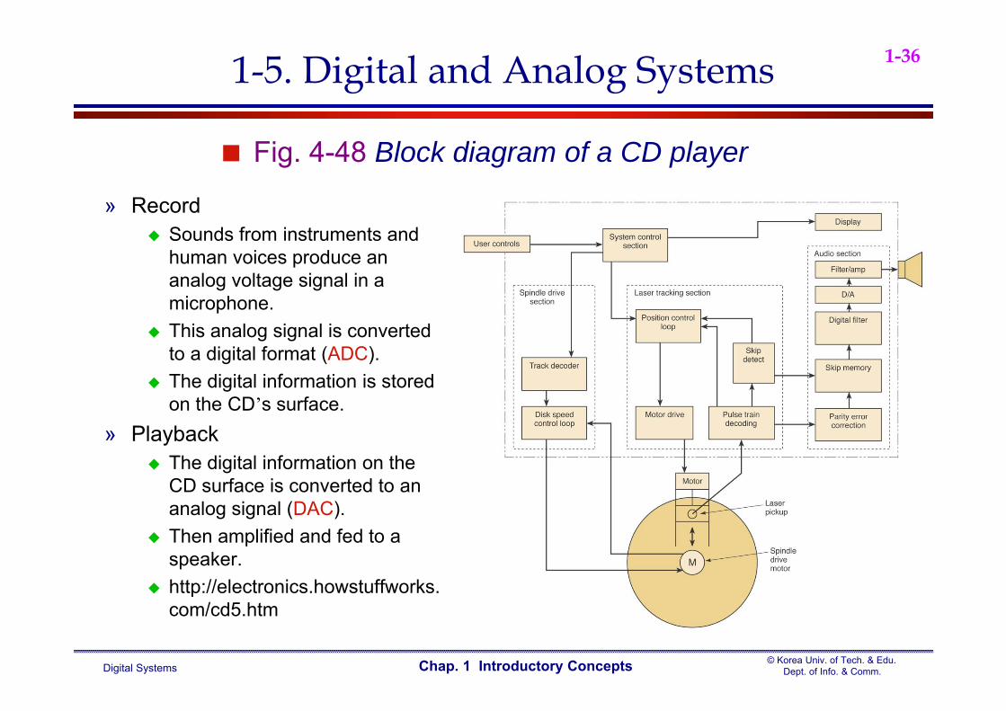
2) CD Player : Fig. 4-48 mixed systems
3) Magnetic levitation system : totally analog approach
1-5. Digital and Analog Systems
Digital Systems© Korea Univ. of Tech. & Edu.
Dept. of Info. & Comm.Chap. 1 Introductory Concepts
1-33
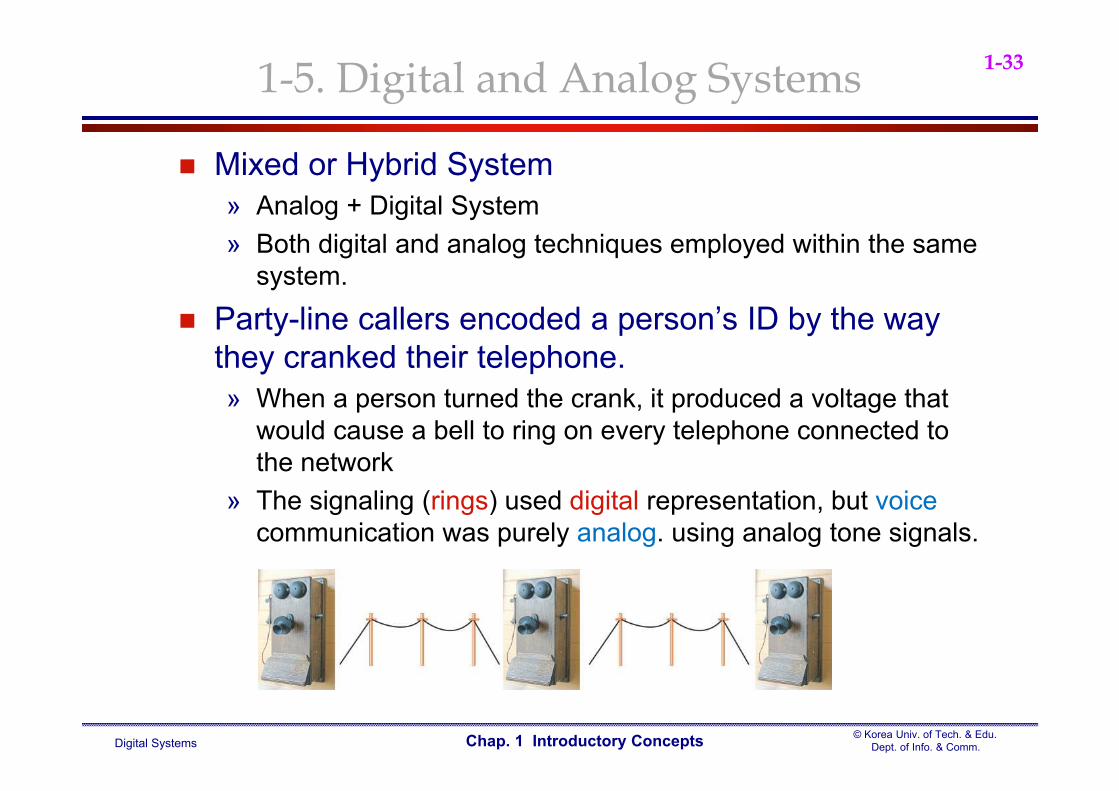
Mixed or Hybrid System » Analog + Digital System» Both digital and analog techniques employed within the same
system. Party-line callers encoded a person’s ID by the way
they cranked their telephone. » When a person turned the crank, it produced a voltage that
would cause a bell to ring on every telephone connected to the network
» The signaling (rings) used digital representation, but voicecommunication was purely analog. using analog tone signals.
1-5. Digital and Analog Systems
Digital Systems© Korea Univ. of Tech. & Edu.
Dept. of Info. & Comm.Chap. 1 Introductory Concepts
1-34
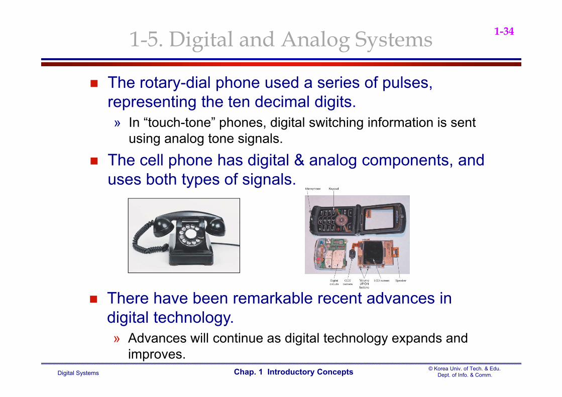
The rotary-dial phone used a series of pulses, representing the ten decimal digits. » In “touch-tone” phones, digital switching information is sent
using analog tone signals. The cell phone has digital & analog components, and
uses both types of signals.
There have been remarkable recent advances in digital technology.» Advances will continue as digital technology expands and
improves.
1-5. Digital and Analog Systems
Digital Systems© Korea Univ. of Tech. & Edu.
Dept. of Info. & Comm.Chap. 1 Introductory Concepts
1-35
Fig. 1-12 Digital Temperature Control System» requires analog/digital conversions to allow the use of
digital processing techniques.
1-5. Digital and Analog Systems
Digital Systems© Korea Univ. of Tech. & Edu.
Dept. of Info. & Comm.Chap. 1 Introductory Concepts
1-36
Fig. 4-48 Block diagram of a CD player
» Record Sounds from instruments and
human voices produce an analog voltage signal in a microphone.
This analog signal is converted to a digital format (ADC).
The digital information is stored on the CD’s surface.
» Playback The digital information on the
CD surface is converted to an analog signal (DAC).
Then amplified and fed to a speaker.
http://electronics.howstuffworks.com/cd5.htm
1-5. Digital and Analog Systems

Digital Systems© Korea Univ. of Tech. & Edu.
Dept. of Info. & Comm.Chap. 1 Introductory Concepts
1-37
Magnetic Levitation SystemTotally analog approach
» Electro-magnet : winding a coil of wire and controlling the amount of current through the coil.
» Infrared light beam : the position of the metal object is measured.
1-5. Digital and Analog Systems

Digital Systems© Korea Univ. of Tech. & Edu.
Dept. of Info. & Comm.Chap. 1 Introductory Concepts
1-381-6 Digital Number Systems
Most common number systems» Decimal, Binary, Octal, Hexadecimal
Decimal System/Base-10 System» Composed of 10 symbols or numerals
0, 1, 2, 3, 4, 5, 6, 7, 8, 9» Positional-value(weight) System
Value of digit depends on position Fig. 1-13 Decimal position values as powers of 10
» Decimal Counting Fig. 1-14 Decimal counting
» With n digits 10n different numbers 10n - 1 largest number
Digital Systems© Korea Univ. of Tech. & Edu.
Dept. of Info. & Comm.Chap. 1 Introductory Concepts
1-39
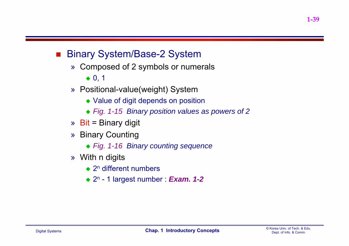
Binary System/Base-2 System» Composed of 2 symbols or numerals
0, 1» Positional-value(weight) System
Value of digit depends on position Fig. 1-15 Binary position values as powers of 2
» Bit = Binary digit» Binary Counting
Fig. 1-16 Binary counting sequence» With n digits
2n different numbers 2n - 1 largest number : Exam. 1-2

Digital Systems© Korea Univ. of Tech. & Edu.
Dept. of Info. & Comm.Chap. 1 Introductory Concepts
1-40
Representing Binary Quantities» Use any device with only two states
Switch, Punched paper tape, Wiring matrix, Light bulb, Diode, Relay, Transistor, Photocell, Thermostat, Mechanical clutch
(a) switch, (b) punched paper tape, (c) wiring matrix
1-7 Representing Signals with Numeric Quantities

Digital Systems© Korea Univ. of Tech. & Edu.
Dept. of Info. & Comm.Chap. 1 Introductory Concepts
1-41
» Temperature data sampled hourly. Fig. 1-17 Red line indicates analog, and the data you have recorded is digital
because you assigned a discrete integer number to the quantity each hour.
Fig. 1-17 shows a continuous plot of the temperature on an early summer day which starts out cool but warms up rapidly around 10 am.
After 11 am, a thunderstorm comes through and the temperature drops very suddenly and drastically.
1-7 Representing Signals with Numeric Quantities
Digital Systems© Korea Univ. of Tech. & Edu.
Dept. of Info. & Comm.Chap. 1 Introductory Concepts
1-42
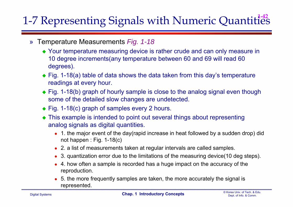
» Temperature Measurements Fig. 1-18 Your temperature measuring device is rather crude and can only measure in
10 degree increments(any temperature between 60 and 69 will read 60 degrees).
Fig. 1-18(a) table of data shows the data taken from this day’s temperature readings at every hour.
Fig. 1-18(b) graph of hourly sample is close to the analog signal even though some of the detailed slow changes are undetected.
Fig. 1-18(c) graph of samples every 2 hours. This example is intended to point out several things about representing
analog signals as digital quantities. 1. the major event of the day(rapid increase in heat followed by a sudden drop) did
not happen : Fig. 1-18(c) 2. a list of measurements taken at regular intervals are called samples. 3. quantization error due to the limitations of the measuring device(10 deg steps). 4. how often a sample is recorded has a huge impact on the accuracy of the
reproduction. 5. the more frequently samples are taken, the more accurately the signal is
represented.
1-7 Representing Signals with Numeric Quantities

Digital Systems© Korea Univ. of Tech. & Edu.
Dept. of Info. & Comm.Chap. 1 Introductory Concepts
1-431-7 Representing Signals with Numeric Quantities
Fig. 1-18
Digital Systems© Korea Univ. of Tech. & Edu.
Dept. of Info. & Comm.Chap. 1 Introductory Concepts
1-441-8 Parallel and Serial Transmission
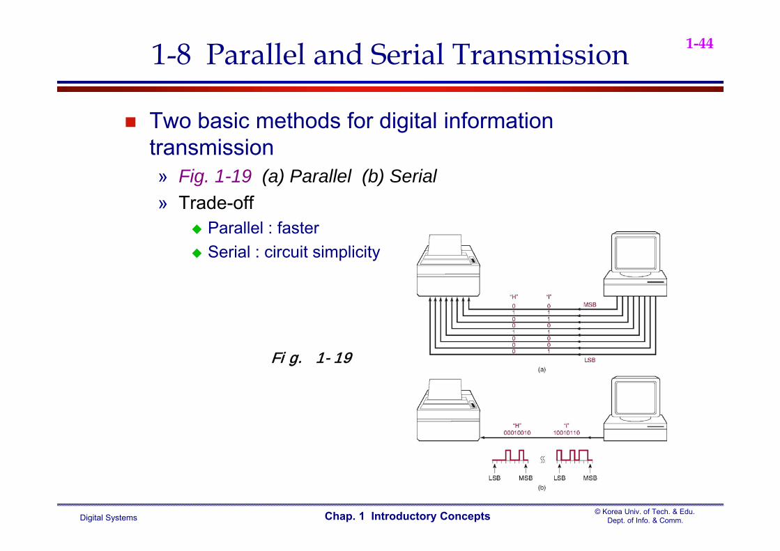
Two basic methods for digital information transmission» Fig. 1-19 (a) Parallel (b) Serial» Trade-off
Parallel : faster Serial : circuit simplicity
Fig. 1-19
Digital Systems© Korea Univ. of Tech. & Edu.
Dept. of Info. & Comm.Chap. 1 Introductory Concepts
1-451-9 Memory
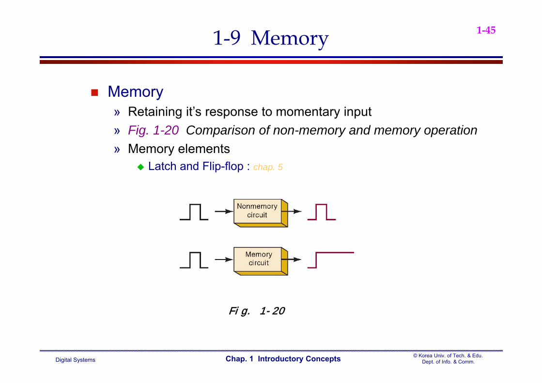
Memory» Retaining it’s response to momentary input» Fig. 1-20 Comparison of non-memory and memory operation» Memory elements
Latch and Flip-flop : chap. 5
Fig. 1-20
Digital Systems© Korea Univ. of Tech. & Edu.
Dept. of Info. & Comm.Chap. 1 Introductory Concepts
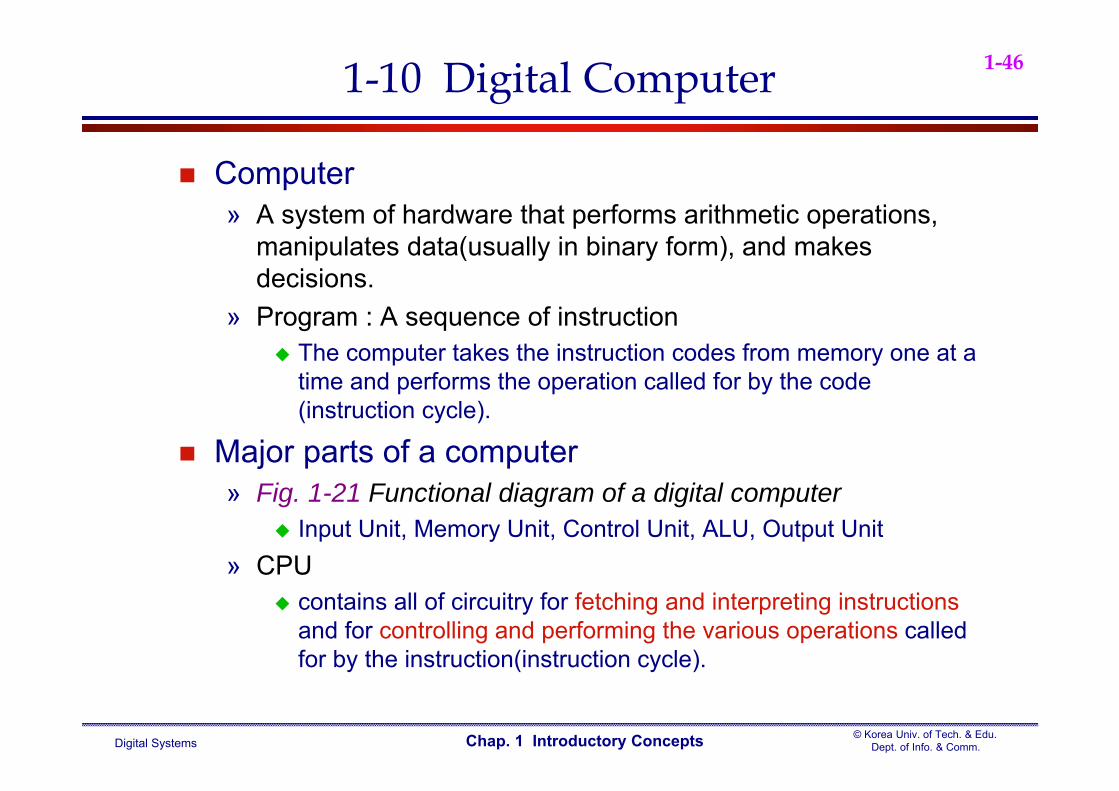
1-461-10 Digital Computer
Computer» A system of hardware that performs arithmetic operations,
manipulates data(usually in binary form), and makes decisions.
» Program : A sequence of instruction The computer takes the instruction codes from memory one at a
time and performs the operation called for by the code (instruction cycle).
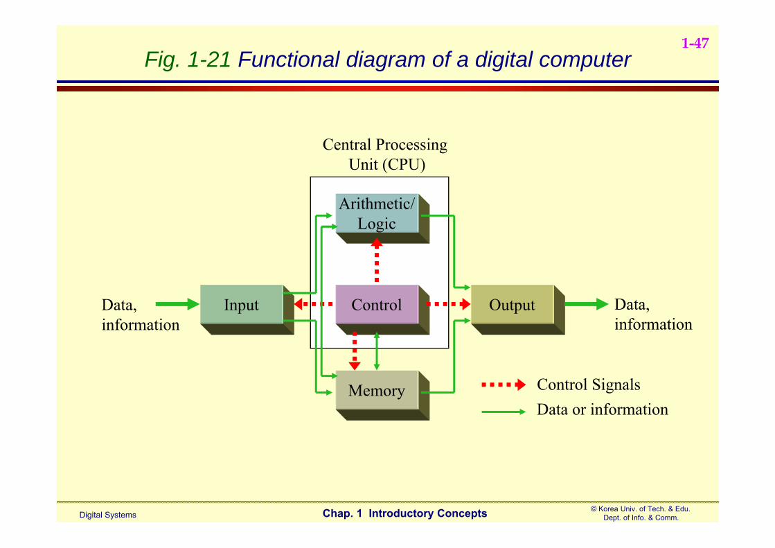
Major parts of a computer» Fig. 1-21 Functional diagram of a digital computer
Input Unit, Memory Unit, Control Unit, ALU, Output Unit» CPU
contains all of circuitry for fetching and interpreting instructionsand for controlling and performing the various operations called for by the instruction(instruction cycle).
Digital Systems© Korea Univ. of Tech. & Edu.
Dept. of Info. & Comm.Chap. 1 Introductory Concepts
1-47Fig. 1-21 Functional diagram of a digital computer
Input Control
Arithmetic/Logic
Memory
Output Data,information
Data,information
Control SignalsData or information
Central Processing Unit (CPU)

Digital Systems© Korea Univ. of Tech. & Edu.
Dept. of Info. & Comm.Chap. 1 Introductory Concepts
1-48
Types of computers» There are many ways to categorize computers and many names for different types of
computers» Classification rule: physical size, operating speed, memory capacity, computational
power, cost» Classified according to Physical size
microcomputer, minicomputer(workstation), mainframe, super» Microcomputer
Smallest type of computers consists of several IC chips including a microprocessor chip, memory chip, and
input/output interface chip. » Microprocessor(=CPU)
contains the control unit, the ALU and the register “CPU on a chip” in other words
» Microcontroller Not a general-purpose, Dedicated or Embedded controller Microcomputers surrounded by specialized support hardware to make it easy to
control things All in a single integrated circuit = Single chip microcontroller (included in I/Os &
memory)
1-10 Digital Computer
Digital Systems© Korea Univ. of Tech. & Edu.
Dept. of Info. & Comm.Chap. 1 Introductory Concepts
1-49
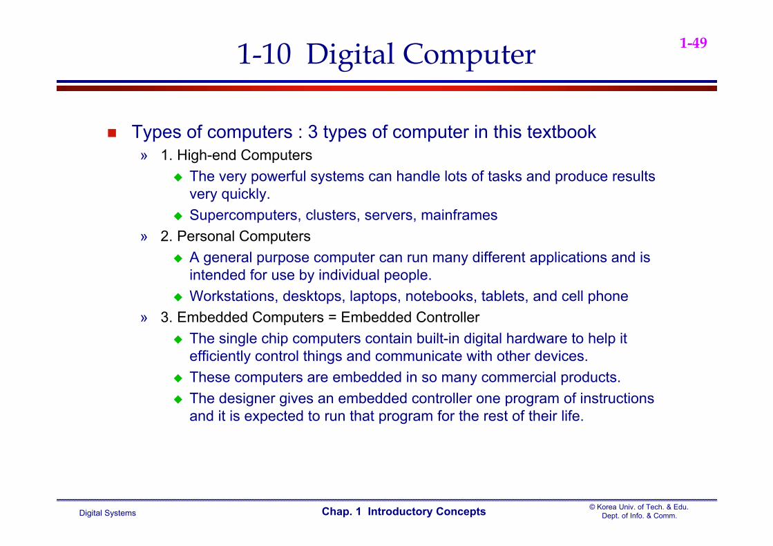
Types of computers : 3 types of computer in this textbook» 1. High-end Computers
The very powerful systems can handle lots of tasks and produce results very quickly.
Supercomputers, clusters, servers, mainframes» 2. Personal Computers
A general purpose computer can run many different applications and is intended for use by individual people.
Workstations, desktops, laptops, notebooks, tablets, and cell phone» 3. Embedded Computers = Embedded Controller
The single chip computers contain built-in digital hardware to help it efficiently control things and communicate with other devices.
These computers are embedded in so many commercial products. The designer gives an embedded controller one program of instructions
and it is expected to run that program for the rest of their life.
1-10 Digital Computer
Digital Systems© Korea Univ. of Tech. & Edu.
Dept. of Info. & Comm.Chap. 1 Introductory Concepts
1-50
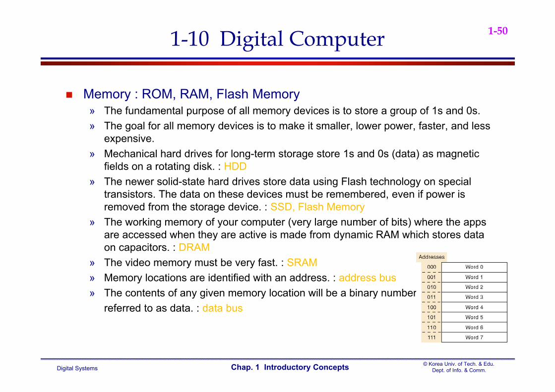
Memory : ROM, RAM, Flash Memory» The fundamental purpose of all memory devices is to store a group of 1s and 0s.» The goal for all memory devices is to make it smaller, lower power, faster, and less
expensive. » Mechanical hard drives for long-term storage store 1s and 0s (data) as magnetic
fields on a rotating disk. : HDD» The newer solid-state hard drives store data using Flash technology on special
transistors. The data on these devices must be remembered, even if power is removed from the storage device. : SSD, Flash Memory
» The working memory of your computer (very large number of bits) where the apps are accessed when they are active is made from dynamic RAM which stores data on capacitors. : DRAM
» The video memory must be very fast. : SRAM» Memory locations are identified with an address. : address bus» The contents of any given memory location will be a binary number
referred to as data. : data bus
1-10 Digital Computer
Digital Systems© Korea Univ. of Tech. & Edu.
Dept. of Info. & Comm.Chap. 1 Introductory Concepts
1-51
Embedded Computers in Cell phones» A complete microcomputer system (embedded in each
phone) controls the digital subsystems and other build-in applications of a cell phone
» Exam 1-3) The roll of your cell phone’s embedded computer» ALU is in the CPU within the microcomputer
ALU is a digital circuit that can perform basic arithmetic by adding binary numbers
Addition, subtraction, division, and multiplication -Chap. 6» Memory, Video, Audio
CCD has many little rows and columns of sensors that measure light and produce a binary number that represents the brightness of each spot, then these binary numbers are stored in the memory : Fig. 1-19(a), (b) – Chap. 5/7/11/12
Displaying the image on an LCD screen is the reverse process of storing an image in memory : Fig. 1-19(c)
1-10 Digital Computer
Digital Systems© Korea Univ. of Tech. & Edu.
Dept. of Info. & Comm.Chap. 1 Introductory Concepts
1-52
» Memory, Video, Audio – continued.
The voice signal from your microphone is converted to a string of digital(binary), then these binary numbers are transmitted using an analog radio frequency.- Chap. 9
Digital Progress Today and Tomorrow» You will be able to become one of the pioneers on the these
new frontiers of technology The FCC is discontinuing the analog transmission of the NTSC
format TV (Digital HDTV revolution) Wireless WIFI networks allow us to use computers on line in
restaurants, airports, and all over campus Your GPS system picks up microwave signals from space to tell
you exactly where you are on a map of the world Farmers let their tractors drive themselves through the fields How soon the car drive itself?
1-10 Digital Computer

Digital Systems© Korea Univ. of Tech. & Edu.
Dept. of Info. & Comm.Chap. 1 Introductory Concepts
1-53
Digital Progress Today and Tomorrow» Why should the contents of this book and the subject of digital
systems matter to you ? To answer that question, just think about the inventions that have
changed how we do things since the year 2000.» If you cannot think of ten examples, use the internet to look for
inventions of the twenty-first century.» As you look at lists generated by lots of people, ask yourself one
simple question: Is any part of this invention a digital system?
» In almost every instance, The answer is YES! » Knowledge of digital systems will help you If you want to be a
part of great innovations of the next 50 years.» As technology makes the building blocks of digital systems
faster, smaller, lower power, and less expensive, you will be able to find new ways to use them to solve the world’s problems.
1-10 Digital Computer

Digital Systems© Korea Univ. of Tech. & Edu.
Dept. of Info. & Comm.Chap. 1 Introductory Concepts
1-54Minicomputer
Handles processing asks for multiple users
Helps small and medium businesses with tasks such as:
» Payroll» Engineering» Accounting
Digital Systems© Korea Univ. of Tech. & Edu.
Dept. of Info. & Comm.Chap. 1 Introductory Concepts
1-55
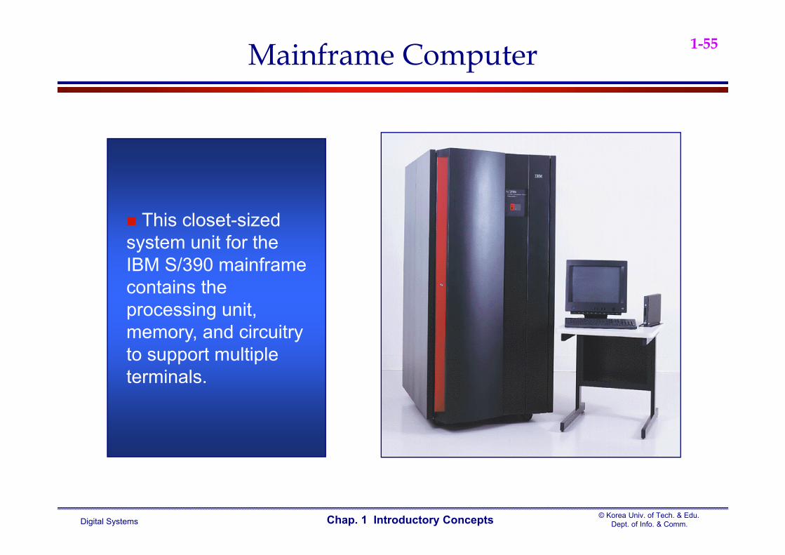
This closet-sized system unit for the IBM S/390 mainframe contains the processing unit, memory, and circuitry to support multiple terminals.
Mainframe Computer
Digital Systems© Korea Univ. of Tech. & Edu.
Dept. of Info. & Comm.Chap. 1 Introductory Concepts
1-56
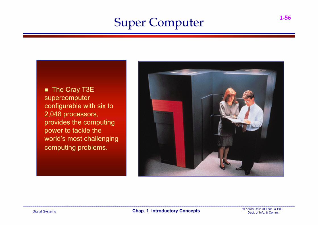
The Cray T3E supercomputer configurable with six to 2,048 processors, provides the computing power to tackle the world’s most challenging computing problems.
Super Computer
Related Documents