DIGIMIC® Digital Discussion System - wired Operating instructions Version 1.42

Welcome message from author
This document is posted to help you gain knowledge. Please leave a comment to let me know what you think about it! Share it to your friends and learn new things together.
Transcript

DIGIMIC® Digital Discussion System - wired
Operating instructions Version 1.42
2 DIGIMIC® wired
Printed in Germany Should you have any questions about this manual please contact: Brähler ICS Konferenztechnik International Congress Service AG P.O. Box 3264 53627 Königswinter, Germany T +49 (0)2244 930-0 F +49 (0)2244 930-450 [email protected] You will find further information about our products on the internet at: www.braehler.com NOTICE: Changes or modifications made to this equipment not expressly approved by BRÄHLER ICS may void the FCC authorization to operate this equipment. © 2011 BRÄHLER ICS AG, Königswinter, Germany All rights reserved, especially (also partly) the translation, reprint, reproduction through copying or other similar methods. BRÄHLER ICS reserves the right to make changes without notice. Operating instructions DIGIMIC wired Feb-2012
DIGIMIC® wired 3
Table of contents About this manual ............................................................................................. 7
Symbols ................................................................................................................... 7 General information ................................................................................................... 7
Important information ........................................................................................ 8 Important safety instructions ...................................................................................... 8 Important safety information ....................................................................................... 9
DIGIMIC® Digital Conference System .................................................................. 11 Wired system components ....................................................................................... 11 Wireless system components (as extension) ............................................................... 11 CE Conformity and FCC Statement ............................................................................ 12
QuickStart ...................................................................................................... 13 System overview .................................................................................................... 14
Basic discussion system ..................................................................................................... 14 DCen connection ............................................................................................................... 15 DChair and DMic connection ............................................................................................... 15 CChair and CMic connection ............................................................................................... 16
System startup ....................................................................................................... 17 Overview of conference modes (microphone switching) ......................................................... 17 Status display ................................................................................................................... 17 Factory settings ................................................................................................................ 18 Recall factory settings ........................................................................................................ 18 Key lock ........................................................................................................................... 18
Applications ........................................................................................................... 19 Extension to the interpreter application ................................................................................ 19 Software remote control application..................................................................................... 20
Software remote control application sample ....................................................................... 20 Upgrating to wireless application ......................................................................................... 21
Wireless application sample ............................................................................................. 21 Audio and loudspeaker system applications .......................................................................... 22 DEFAULT audio routing ...................................................................................................... 22
DEFAULT audio routing sample ........................................................................................ 23 CHAIRPERSON audio routing .............................................................................................. 24
CHAIRPERSON audio routing sample ................................................................................ 25 INDIVIDUAL audio routing .................................................................................................. 26
INDIVIDUAL audio routing sample .................................................................................... 26
Central Control Unit DCen ................................................................................ 27 Operating controls and connections - overview ........................................................... 27 Operating controls and connections – description ........................................................ 28
Front controls ................................................................................................................... 28 Rear connections ............................................................................................................... 29
Operation ............................................................................................................... 33 Display and operating buttons ............................................................................................. 33 Start-up screen ................................................................................................................. 33

DIGIMIC® wired 4
Main menu ....................................................................................................................... 34 Menu locking ................................................................................................................. 34 Display Line 1 - Menu bar ............................................................................................... 35 Display Line 2 - Units ..................................................................................................... 35 Display Line 3 - Conference parameters ............................................................................ 36
Priority on/off ............................................................................................................. 36 Permanent or temporary muting of the delegates units .................................................... 36 Max. numbers of active DELegate microphones .............................................................. 36 Max. numbers of active VIP microphones ....................................................................... 36
Display Line 4 - Volume control and audio routing .............................................................. 36 Volume control ........................................................................................................... 36
INTernal or EXTernal audio source .................................................................................... 37 Network activity ............................................................................................................ 37
Conference modes ...................................................................................................... 38 AUTomatic conference modes ...................................................................................... 38 MANual conference mode ............................................................................................ 39
Line Status menu ........................................................................................................... 39 Found Total ................................................................................................................ 39
Lost Total ..................................................................................................................... 39 Other Device ................................................................................................................. 40 Clean UnitList ................................................................................................................ 40 Table: Context dependence in the Line Status menu ........................................................... 41 Seats Configuration menu ............................................................................................... 42
Seat Numbering .......................................................................................................... 42 Automatic Numbering (Seat-ID) .................................................................................... 43 Manual Numbering (Seat-ID) ......................................................................................... 45 Erase Numbering ......................................................................................................... 46 Show Chairperson ....................................................................................................... 46 Show/Edit VIPs ........................................................................................................... 47
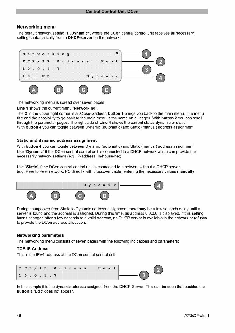
Networking menu ........................................................................................................... 48 Static and dynamic address assignment ......................................................................... 48 Networking parameters ................................................................................................ 48
TCP/IP Address ........................................................................................................ 48 Network Mask ......................................................................................................... 49 Default Gateway ...................................................................................................... 49 Time Server ............................................................................................................. 49 SysLog Server ......................................................................................................... 49 DHCP Server ........................................................................................................... 49 MAC Address .......................................................................................................... 50
Ethernet line status ..................................................................................................... 50 Editing of a network address ........................................................................................ 50
Audio menu ...................................................................................................................... 51 DEFAULT audio routing ................................................................................................... 51 CHAIRPERSON audio routing ........................................................................................... 51 OR + 4CH routing ......................................................................................................... 52 INDIVIDUAL audio routing ............................................................................................... 52
Audio Matrix Edit menu ..................................................................................................... 52

DIGIMIC® wired 5
Audio-Matrix Line Channels Menu .................................................................................... 54 Audio-Matrix Interpreter Channels Menu ............................................................................ 54 Audio-Matrix Call Channels Menu ..................................................................................... 55
Advanced Audio Routing Menu ........................................................................................... 55
Configuration menu ................................................................................................. 57 Interpretation menu ........................................................................................................... 58
Language List Menu ........................................................................................................ 58 Booth Numbers Menu ..................................................................................................... 59 Takeover Mode .............................................................................................................. 59
Individual Takeover Mode Menu ................................................................................. 60 DDol Channel Locking Menu ............................................................................................ 61 Reset Interpretation Values to Default Menu ...................................................................... 61
Voice Activation (VOX) ...................................................................................................... 62 DSpark Settings ................................................................................................................ 66
Register Control ....................................................................................................... 66 Standby Timeout ...................................................................................................... 67 Multi-Room Control ................................................................................................... 68 Protocol Selection ..................................................................................................... 68 RF Power ................................................................................................................ 69 RF Spectrum Setting ................................................................................................. 69 Configuration File ..................................................................................................... 70 Register File ............................................................................................................. 71 System Info ............................................................................................................. 71 Factory defaults DSpark ............................................................................................ 72
Audio Boost ...................................................................................................................... 73 DCen Factory defaults ........................................................................................................ 74
Setting Storage Menu ..................................................................................................... 74 Push to talk ...................................................................................................................... 75
Chairpersons Conference Unit DChair ................................................................ 76 User controls and connections .................................................................................. 76
Delegates´ Conference Unit DMic ..................................................................... 77 User controls and connections .................................................................................. 77
Classic Chairpersons Conference Unit CChair ..................................................... 78 User controls and connections .................................................................................. 78
Classic Delegates´ Conference Unit CMic .......................................................... 79 User controls and connections .................................................................................. 79
DExt – extension power supply unit .................................................................. 80 Microphones ................................................................................................... 81
TM58/6 Conference Microphone ............................................................................... 81 TMD/01 Shock Mount - Conference Microphone ......................................................... 82 TMD/01 SM-W Conference Microphone ..................................................................... 82
Wireless system expansion ............................................................................... 83 Wireless system components .................................................................................... 83 Radio Transceiver Unit DSpark in combination with DCen ............................................. 84
DIGIMIC® wired 6
DSpark features ................................................................................................................ 84
Docking Unit DDoc .................................................................................................. 85 DDoc features .................................................................................................................. 85
Appendix ........................................................................................................ 87 Sample applications ................................................................................................. 87
DIGIMIC Discussion system – wired, with extension power supply ......................................... 87 DIGIMIC Discussion system - wireless ................................................................................. 90 DIGIMIC Discussion system - wired and wireless .................................................................. 92
Technical Data........................................................................................................ 94 DCen Central Control Unit .................................................................................................. 94 RS-232 transmission protocol ............................................................................................. 95
Pinouts ......................................................................................................................... 95 Signals .......................................................................................................................... 95
D9 system cable ............................................................................................................... 96 Connection diagram of microphone units DMic / DChair ......................................................... 96 Connection diagram of microphone units CMic / CChair ......................................................... 96
Troubleshooting table .............................................................................................. 97 Table of language sign (ISO639-2) ............................................................................ 98 Templates for individual audio routing settings .......................................................... 101 SERVICE FORM .................................................................................................... 105 Index ................................................................................................................... 107 Contact information .............................................................................................. 109

About this manual
DIGIMIC® wired 7
About this manual Please keep this manual together with the system units. If you pass on the units to other parties, please include this manual.
Symbols The meanings of the symbols and fonts used in this manual are as follows:
Indicates an important note, if not minded, the functionality of the unit, the security of your data, or your health are put at risk.
Supplementary information, remarks, and tips follow this symbol.
Text which follows this symbol describes activities that must be performed in the order shown.
Texts in bolded letters require your special attention.
General information
Please read the manual carefully, taking special care when you see this symbol as indicates important information! All trademarks (marked with *) and trade names are the property of their respective holders The warranty invalidates, if you cause (generate, precipitate) inappropriate use or handling of the unit.
Important information
DIGIMIC® wired 8
Important information Important safety instructions
Read these instructions for use.
Keep these instructions in a safe place.
Heed all warnings.
Follow all instructions.
Do not use near water.
Clean only with a dry cloth.
Do not block any ventilation openings. Install in accordance with the manufacturer’s instructions.
Do not install near any heat sources such as central heating radiators, electric heaters, stoves, or other units that produce heat (e.g. amplifiers).
This unit is supplied with an IEC mains cable complete with a molded mains plug. This is for your safety – do not tamper with the mains. If the supplied cable does not fit your mains socket, please consult a competent electrician for a replacement cable that matches the power output sockets in your country, or to replace the obsolete socket with one to current standards.
Protect the mains cable from being walked on or pinched, particularly at plugs, convenience receptacles, and the point where it exits from the unit.
Only use attachments/accessories specified by the manufacturer.
Use only with the cart, stand, tripod, bracket, or table specified by the manufacturer, or sold with the unit. When a cart is used, use caution when moving the cart/unit combination to avoid injury from tip-over.
Unplug during lightning storms or when unused for long periods of time.
Refer all servicing to qualified service personnel. Servicing is required if the unit has been damaged in any way, such as mains cable or plug damage, liquid has been spilled, objects have fallen inside, the unit has been exposed to rain or moisture, does not operate properly or has been dropped.
Important safety information
DIGIMIC® wired 9
Important safety information
Warning! To reduce the risk of fire or electric shock, do not expose the unit to rain or moisture. Do not open the unit as there are potentially dangerous voltages present inside. Refer all servicing to qualified service personnel. Caution! Use only accessories recommended by the manufacturer to avoid fire, electric shock, or other hazards. To prevent the risk of electric shock, do not remove cover or back. No user serviceable parts inside! Refer all servicing to qualified service personnel. Warning! Power source The central control unit is a Class 1 unit. It must only be connected to properly grounded power outlets. This unit should be operated only from the type of power source indicated on the marking label. lf you are not sure of the type of power supply to your building, consult your dealer or local power company. Disconnection from the mains To disconnect the equipment from the mains remove the mains plug from the mains outlet. Where the mains plug or an appliance coupler is used as the disconnect device, the disconnect device shall remain readily operable. Overload Do not overload wall outlets and extension cables as this may result in fire and electric shock. Objects and liquids Never push objects of any kind through openings of this unit as they may touch dangerous voltage points or short-out parts that could result in fire or electric shock. Never spill liquids of any kind onto the unit. Should a spillage occur, unplug the unit and have it checked by a technician. Maintenance and care No user serviceable parts inside! Do not attempt to service this unit yourself as opening or removing covers may expose dangerous voltage or other hazards. Leave all service work to authorized expert personnel. Clean only with a dry cloth. Do not use detergents or other liquids. Never use solvents as this damage the surface. Replacement parts When replacement parts are required, be sure the service technician uses replacement parts specified by the manufacturer or those that have the same characteristics as the original part. Unauthorized substitutions may result in fire, electric shock, or other hazards. Safety check Upon completion of any service or repairs to this unit, ask the service technician to perform safety checks to determine that the product is in proper operating condition. The DIGIMIC conference system is state of the art and has been designed to meet the regulations in force. Nevertheless, the individual components of the DIGIMIC conference system can cause danger for persons and material assets if:
the system is not used as intended
the system is set up by personnel not familiar with the safety regulations
the system is converted or altered incorrectly
the safety instructions are not observed

Important information
DIGIMIC® wired 10
This system is capable of producing sound pressure exceeding 85 dB (A). 85 dB (A) is the sound pressure corresponding to the maximum permissible volume which is by law (in some countries) allowed to affect your hearing for the duration of a working day. It is used as a basis according to the specifications of industrial medicine. Higher volumes or longer durations can damage your hearing. At higher volumes, the duration must be shortened in order to prevent hearing damage.
The following are sure signs that you have been subjected to excessive noise for too long a time:
You can hear ringing or whistling sounds in your ears.
You have the impression (even for a short time only) that you can no longer hear high notes. Disposal
This symbol on the product, in the instructions or on the packaging means that your electrical and electronic equipment should be disposed at the end of its life separately from your household waste. There are separate collection systems for recycling in the EU. For more information, please contact the local authority or your retailer where you purchased the product.
Make sure to dispose of used batteries as required by local waste disposal rules. Never throw batteries into a fire (risk of explosion) or dustbin.
When scrapping the equipment, remove the batteries, separate the case, circuit boards, and cables, and dispose of all components in accordance with local waste disposal rules.
DIGIMIC® Digital Conference System
DIGIMIC® wired 11
DIGIMIC® Digital Conference System
Thank you choosing the DIGIMIC conference system from BRÄHLER ICS! You have invested in reliably conference equipment.
DIGIMIC stands for digitally controlled microphone management system.
The digital conference system provides a 100% standalone solution and is completely self-configuring. DIGIMIC matches digital broadcast and studio audio requirements, meeting the needs of today’s conferencing world. At any time the system can be expanded to include our conference software. TCP/ IP communication is utilized to offer microphone control and name handling as well as other conference requirements.
The delegate’s frontend – the microphone units DMic and CMic – offers a thoughtful ergonomic design enabling the delegate to concentrate on the conference.
Wired system components • DCen Central Control Unit
• DChair Chairpersons Conference Unit
• DMic Delegates´ Conference Unit
• CMic Delegates´ Conference Unit classic
• CChair Chairpersons Conference Unit classic
• TMD/01 Conference Microphone
• TM58/6 Conference Microphone
• D9 System cable different lengths available
• Country-specific mains cables (see details on page 94)
Wireless system components (as extension) • DSpark Radio Transceiver Unit
• DChair Chairpersons Conference Unit
• DMic Delegates´ Conference Unit
• DDoc Docking Unit for DChair/DMic
• TMD/01 Conference Microphone
• TM58/6 Conference Microphone
• DTray Charging and Transport Tray for 10 rechargeable batteries
• DPack Transport Case for 10 DIGIMIC wireless units DMic+DDoc
• Antennas for DSpark Radio Transceiver Unit
• Country-specific mains cables (see details in the wireless system manual)

DIGIMIC® Digital Conference System
DIGIMIC® wired 12
CE Conformity and FCC Statement The DIGIMIC equipment complies with international standards IEC 914, ISO 4043, ISO 2603, DIN 56924
This equipment has been tested and found to comply with the limits of the European Council Directive on the approximation of the member states relating to electromagnetic compatibility (98/336/EEC) according to EN 55022 Class A.
This equipment has been tested and found to comply with the limits for a Class A digital device, pursuant to Part 15 of the FCC Rules. These limits are designed to provide reasonable protection against harmful interference in a residential installation. This equipment generates uses and can
radiate radio frequency energy and, if not installed and used in accordance with the instructions, may cause harmful interference to radio communications. However, there is no guarantee that interference will not occur in a particular installation. If this equipment does cause harmful interference to radio or television reception, which can be determined by turning the equipment off and on, the user is encouraged to try to correct the interference by one or more of the following measures: • Reorient or relocate the receiving antenna. • Increase the separation between the equipment and receiver. • Connect the equipment into an outlet on a circuit different from that to which the receiver is connected. • Consult the dealer or an experienced radio/TV technician for help. NOTICE: Changes or modifications made to this equipment not expressly approved by Brähler ICS Konferenztechnik AG may void the FCC authorization to operate this equipment. NOTICE: This device complies with Part 15 of the FCC Rules and with RSS-210 of Industry Canada. Operation is subject to the following two conditions:
(1) this device may not cause harmful interference, and (2) this device must accept any interference received, including interference that may cause undesired
operation. NOTICE: This Class A digital apparatus complies with Canadian ICES-003. Cet appareil numérique de la classe A est conforme à la norme NMB-003 du Canada.
QuickStart
DIGIMIC® wired 13
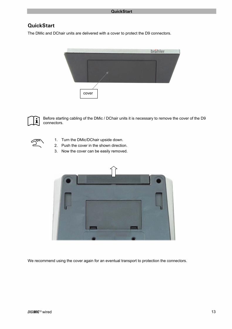
QuickStart The DMic and DChair units are delivered with a cover to protect the D9 connectors.
Before starting cabling of the DMic / DChair units it is necessary to remove the cover of the D9 connectors.
1. Turn the DMic/DChair upside down.
2. Push the cover in the shown direction.
3. Now the cover can be easily removed.
We recommend using the cover again for an eventual transport to protection the connectors.
cover
QuickStart
DIGIMIC® wired 14
System overview
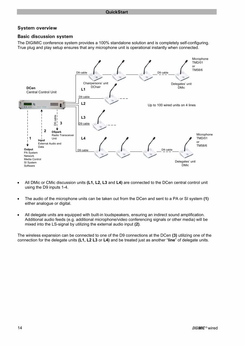
Basic discussion system The DIGIMIC conference system provides a 100% standalone solution and is completely self-configuring. True plug and play setup ensures that any microphone unit is operational instantly when connected.
MicrophoneTMD/01orTM58/6
Up to 100 wired units on 4 lines
D9 cable D9 cable
D9 cable
D9 cable
DSparkRadio Transceiver Unit
D9 cable
DCenCentral Control Unit
D9
cab
le
D9 cable
InputExternal Audio and Data
OutputPA SystemNetworkMedia ControlSI SystemSoftware
Delegates’ unit DMic
Delegates’ unit DMic
Chairpersons’ unit DChair
MicrophoneTMD/01orTM58/6
All DMic or CMic discussion units (L1, L2, L3 and L4) are connected to the DCen central control unit using the D9 inputs 1-4.
The audio of the microphone units can be taken out from the DCen and sent to a PA or SI system (1) either analogue or digital.
All delegate units are equipped with built-in loudspeakers, ensuring an indirect sound amplification. Additional audio feeds (e.g. additional microphone/video conferencing signals or other media) will be mixed into the LS-signal by utilizing the external audio input (2).
The wireless expansion can be connected to one of the D9 connections at the DCen (3) utilizing one of the connection for the delegate units (L1, L2 L3 or L4) and be treated just as another “line” of delegate units.
L1
L2
L3
L4 1
2
3

QuickStart
DIGIMIC® wired 15
DCen connection For the basic functions of the DCen central control unit plug in the mains power connector and at least one system cable from the first conference unit to one of the D9 sockets L1, L2, L3 or L4. Up to 25 conference units can be connected to each line.
DChair and DMic connection For the connection of the DChair and/or DMic conference units plug in the connectors for the previous and next unit. The D9 system cable is a highly flexible shielded CAT5 cable with lockable S8G-connectors. PREVIOUS and NEXT cannot be mixed up accidentally.
from previous unit/DCen To next unit
D9 system cable from/to the first conference unit in line
from previous unit To next unit To previous unit
D9 system cable from/to the first conference unit in line
Mains power connection
QuickStart
DIGIMIC® wired 16
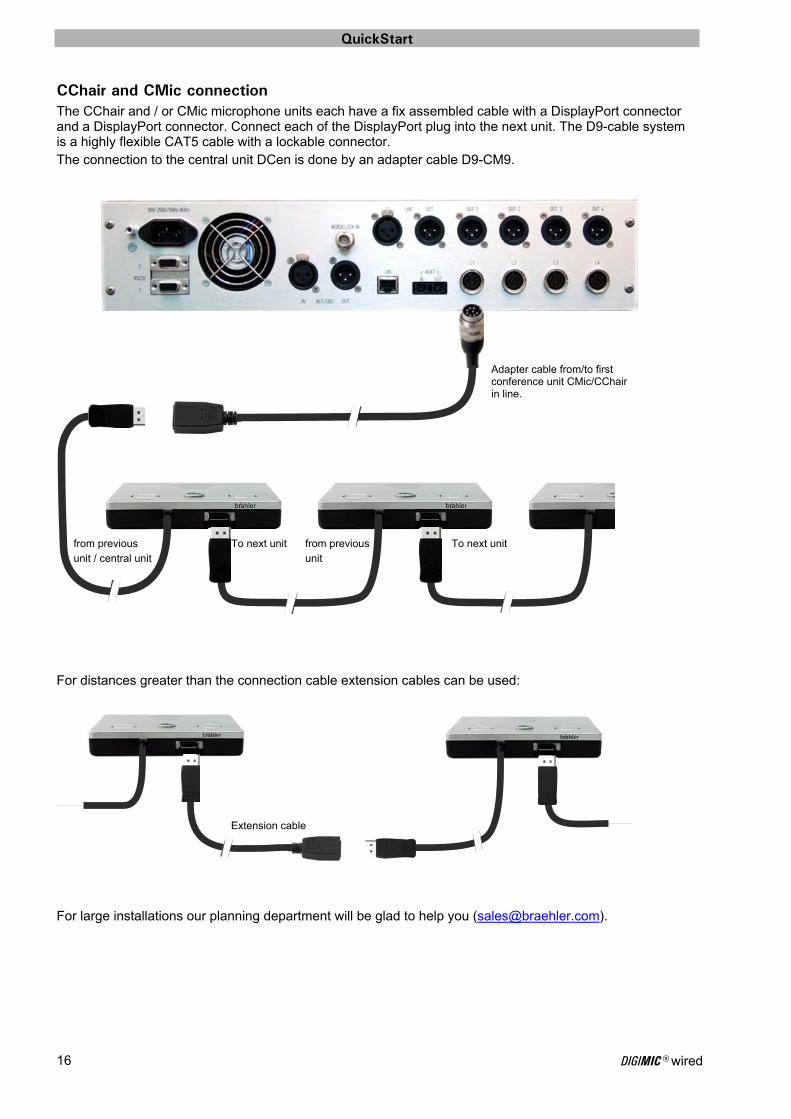
CChair and CMic connection The CChair and / or CMic microphone units each have a fix assembled cable with a DisplayPort connector and a DisplayPort connector. Connect each of the DisplayPort plug into the next unit. The D9-cable system is a highly flexible CAT5 cable with a lockable connector. The connection to the central unit DCen is done by an adapter cable D9-CM9. For distances greater than the connection cable extension cables can be used:
For large installations our planning department will be glad to help you ([email protected]).
Extension cable
Adapter cable from/to first conference unit CMic/CChair in line.
To next unit from previous
unit
To next unit from previous
unit / central unit
QuickStart
DIGIMIC® wired 17
4
DC B A
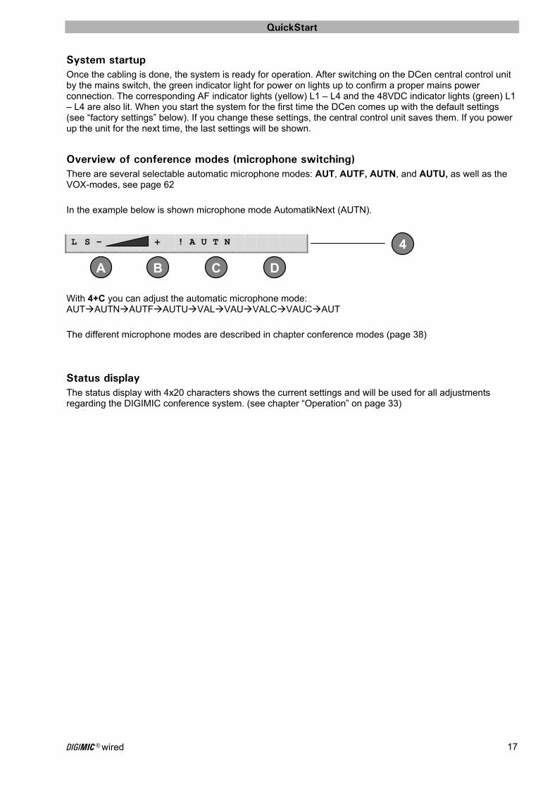
System startup Once the cabling is done, the system is ready for operation. After switching on the DCen central control unit by the mains switch, the green indicator light for power on lights up to confirm a proper mains power connection. The corresponding AF indicator lights (yellow) L1 – L4 and the 48VDC indicator lights (green) L1 – L4 are also lit. When you start the system for the first time the DCen comes up with the default settings (see “factory settings” below). If you change these settings, the central control unit saves them. If you power up the unit for the next time, the last settings will be shown.
Overview of conference modes (microphone switching) There are several selectable automatic microphone modes: AUT, AUTF, AUTN, and AUTU, as well as the VOX-modes, see page 62 In the example below is shown microphone mode AutomatikNext (AUTN).
With 4+C you can adjust the automatic microphone mode: AUTAUTNAUTFAUTUVALVAUVALCVAUCAUT The different microphone modes are described in chapter conference modes (page 38)
Status display The status display with 4x20 characters shows the current settings and will be used for all adjustments regarding the DIGIMIC conference system. (see chapter “Operation” on page 33)
L S - + ! A U T N

QuickStart
DIGIMIC® wired 18
Factory settings When you start the system for the first time the DCen comes up with the factory settings, which enables you to use the microphone system right away with the most common settings without any additional adjustments. Any changes of these parameters will be stored automatically and available when you restart the system the next time. The factory settings can be recalled at any time if required. The factory (default) settings are as follows:
Conference parameters
Priority OFF See page 36
Permanent or Temporary “mute all” PERMANENT See page 36
Max. numbers of active DELegate microphones
DEL3 See page 36
Max. numbers of active VIP microphones
VIP3 See page 36
Volume control and conference modes
Volume control 50% See page 36
Conference modes AUT, AUTN, AUTF, MAN
AUT See page 38
AUTomatic conference modes AUT See page 38
INTernal or EXTernal audio source INTERNAL See page 37
Network menu
Static and dynamic address assignment
DYNAMIC See page 48
TCP/IP Address Automatic See page 48
Network Mask Automatic See page 49
Default Gateway Automatic See page 49
SysLog Server Automatic See page 49
DHCP Server Automatic See page 49
MAC Address Fixed (individual for each DCen)
See page 49
Ethernet line status Automatic entry See page 50
Audio menu
Audio routing DEFAULT See page 55
Audio routing
Default Fixed (not editable) See page 51
Chairman Fixed (not editable) See page 51
Individual Preset 1-8 No entry (editable) See page 52
Recall factory settings The factory settings can be recalled via the “Configuration menu” (please refer to page 51). This action has to be confirmed.
If you recall the factory settings, all individual stored presets will be deleted!
Key lock Press button 1 and then 4 to activate the key lock. The key lock prevents unwanted changing of settings by accidental touching (e.g. cleaning) of the buttons. The key lock will remain active (also after restart of the DCen) until it is disabled. To disable the key lock press 1 and then 4.
QuickStart
DIGIMIC® wired 19
Applications The DIGIMIC system offers a large variety of applications. The following pages reveal some application samples. You will find more sample applications in the chapter “Sample applications” from page 87. A basic application was presented in the previous chapter.
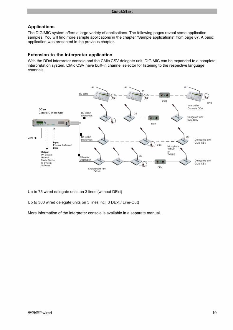
Extension to the interpreter application With the DDol interpreter console and the CMic CSV delegate unit, DIGIMIC can be expanded to a complete interpretation system. CMic CSV have built-in channel selector for listening to the respective language channels.
Up to 75 wired delegate units on 3 lines (without DExt) Up to 300 wired delegate units on 3 lines incl. 3 DExt / Line-Out) More information of the interpreter console is available in a separate manual.
QuickStart
DIGIMIC® wired 20
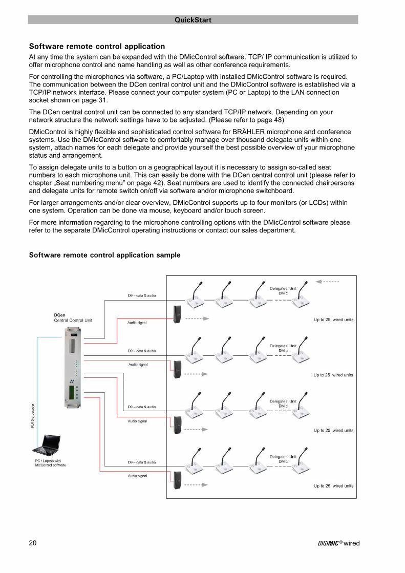
Software remote control application At any time the system can be expanded with the DMicControl software. TCP/ IP communication is utilized to offer microphone control and name handling as well as other conference requirements.
For controlling the microphones via software, a PC/Laptop with installed DMicControl software is required. The communication between the DCen central control unit and the DMicControl software is established via a TCP/IP network interface. Please connect your computer system (PC or Laptop) to the LAN connection socket shown on page 31.
The DCen central control unit can be connected to any standard TCP/IP network. Depending on your network structure the network settings have to be adjusted. (Please refer to page 48)
DMicControl is highly flexible and sophisticated control software for BRÄHLER microphone and conference systems. Use the DMicControl software to comfortably manage over thousand delegate units within one system, attach names for each delegate and provide yourself the best possible overview of your microphone status and arrangement.
To assign delegate units to a button on a geographical layout it is necessary to assign so-called seat numbers to each microphone unit. This can easily be done with the DCen central control unit (please refer to chapter „Seat numbering menu” on page 42). Seat numbers are used to identify the connected chairpersons and delegate units for remote switch on/off via software and/or microphone switchboard.
For larger arrangements and/or clear overview, DMicControl supports up to four monitors (or LCDs) within one system. Operation can be done via mouse, keyboard and/or touch screen.
For more information regarding to the microphone controlling options with the DMicControl software please refer to the separate DMicControl operating instructions or contact our sales department.
Software remote control application sample

QuickStart
DIGIMIC® wired 21
Upgrating to wireless application DIGIMIC microphone units DMic and DChair can be used either wired or wireless! To make a wired unit wireless, simply replace the wire with the docking station, which ensures the reliable communication with the DSpark transmission console. The docking station DDoc transforms the delegate’s conference unit DMic (DChair) into a wireless conference unit, just by sliding in the delegate unit on top. Once the microphone button is pressed the unit will be recognized, and configured completely automatically. The integrated rechargeable lithium-polymer battery ensures continuous operation for up to 20 hours. A low power level of the battery pack will be indicated on the DDoc and within the DCen Control software. The wireless DIGIMIC is based on an intelligent transmission protocol, which assures the audio quality and reliability of a wired conference system, combined with the flexibility and freedom offered by wireless.
Wireless application sample
QuickStart
DIGIMIC® wired 22
Audio and loudspeaker system applications The DCen allows different audio routing settings (see examples on the following pages).
DEFAULT audio routing
CHAIRPERSON audio routing
INDIVIDUAL audio routing To activate one of these settings please refer to page 51.
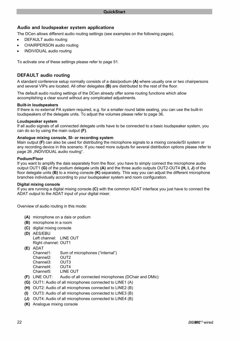
DEFAULT audio routing A standard conference setup normally consists of a dais/podium (A) where usually one or two chairpersons and several VIPs are located. All other delegates (B) are distributed to the rest of the floor.
The default audio routing settings of the DCen already offer some routing functions which allow accomplishing a clear sound without any complicated adjustments.
Built-in loudspeakers If there is no external PA system required, e.g. for a smaller round table seating, you can use the built-in loudspeakers of the delegate units. To adjust the volumes please refer to page 36.
Loudspeaker system If all audio signals of all connected delegate units have to be connected to a basic loudspeaker system, you can do so by using the main output (F).
Analogue mixing console, SI- or recording system Main output (F) can also be used for distributing the microphone signals to a mixing console/SI system or any recording device in this scenario. If you need more outputs for several distribution options please refer to page 26 „INDIVIDUAL audio routing“.
Podium/Floor If you want to amplify the dais separately from the floor, you have to simply connect the microphone audio output OUT1 (G) of the podium delegate units (A) and the three audio outputs OUT2-OUT4 (H, I, J) of the floor delegate units (B) to a mixing console (K) separately. This way you can adjust the different microphone branches individually according to your loudspeaker system and room configuration.
Digital mixing console If you are running a digital mixing console (C) with the common ADAT interface you just have to connect the ADAT output to the ADAT input of your digital mixer.
Overview of audio routing in this mode:
(A) microphone on a dais or podium (B) microphone in a room (C) digital mixing console (D) AES/EBU
Left channel: LINE OUT Right channel: OUT1
(E) ADAT Channel1: Sum of microphones (“internal”) Channel2: OUT2 Channel3: OUT3 Channel4: OUT4 Channel5: LINE OUT
(F) LINE OUT: Audio of all connected microphones (DChair and DMic) (G) OUT1: Audio of all microphones connected to LINE1 (A) (H) OUT2: Audio of all microphones connected to LINE2 (B) (I) OUT3: Audio of all microphones connected to LINE3 (B) (J) OUT4: Audio of all microphones connected to LINE4 (B) (K) Analogue mixing console

QuickStart
DIGIMIC® wired 23
ADAT IN
ADATAusgang
AES/EBU Ausgang
A
B
C
D E
G H
K
F I J
Podium
Delegate Units
All microphones e.g. toPA-, SI- or recording system
to PA system
Digital mixing console
Main + OUT1e.g. to broadcast system
Output
OR + 7 channels
to PA system
DCen rear view
to SI system
to recording system
Chair
Chair
VIP
VIP
Analogue mixing console
DEFAULT audio routing sample The DCen provides both: Analogue and digital interfaces, to match your choice of mixing console, PA- or audio distribution system. In the following you see the default audio routing and device connection possibilities. - 4 branches to one (main) output (F) - 4 branches individually to OUT 1 – OUT 4 (G), (H), (I), (J) - additional digital outputs (D), (E)
QuickStart
DIGIMIC® wired 24
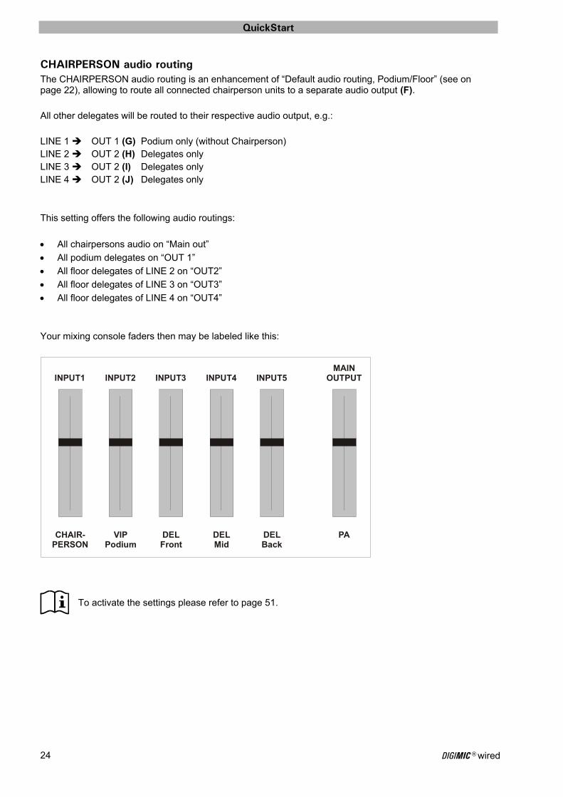
CHAIRPERSON audio routing The CHAIRPERSON audio routing is an enhancement of “Default audio routing, Podium/Floor” (see on page 22), allowing to route all connected chairperson units to a separate audio output (F). All other delegates will be routed to their respective audio output, e.g.: LINE 1 OUT 1 (G) Podium only (without Chairperson) LINE 2 OUT 2 (H) Delegates only LINE 3 OUT 2 (I) Delegates only LINE 4 OUT 2 (J) Delegates only This setting offers the following audio routings:
All chairpersons audio on “Main out”
All podium delegates on “OUT 1”
All floor delegates of LINE 2 on “OUT2”
All floor delegates of LINE 3 on “OUT3”
All floor delegates of LINE 4 on “OUT4” Your mixing console faders then may be labeled like this:
To activate the settings please refer to page 51.
CHAIR- VIP DEL DEL DEL PAPERSON Podium Front Mid Back
MAINOUTPUTINPUT5INPUT4INPUT3INPUT2INPUT1
QuickStart
DIGIMIC® wired 25
ADAT IN
ADATAusgang
AES/EBU Ausgang
A
B
C
D E
G H
K
F I J
Podium
Delegate Units
All microphones e.g. toPA-, SI- or recording system
to PA system
Digital mixing console
Main + OUT1e.g. to broadcast system
Output
OR + 7 channels
to PA system
DCen rear view
to SI system
to recording system
Chair
Chair
VIP
VIP
Analogue mixing console
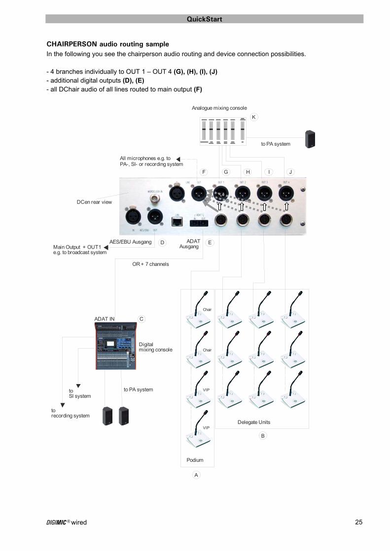
CHAIRPERSON audio routing sample
In the following you see the chairperson audio routing and device connection possibilities. - 4 branches individually to OUT 1 – OUT 4 (G), (H), (I), (J) - additional digital outputs (D), (E) - all DChair audio of all lines routed to main output (F)
QuickStart
DIGIMIC® wired 26
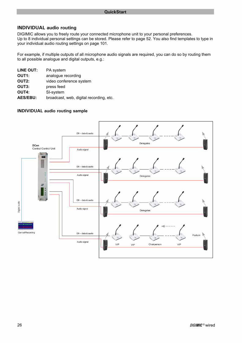
INDIVIDUAL audio routing DIGIMIC allows you to freely route your connected microphone unit to your personal preferences. Up to 8 individual personal settings can be stored. Please refer to page 52. You also find templates to type in your individual audio routing settings on page 101. For example, if multiple outputs of all microphone audio signals are required, you can do so by routing them to all possible analogue and digital outputs, e.g.: LINE OUT: PA system OUT1: analogue recording OUT2: video conference system OUT3: press feed OUT4: SI-system AES/EBU: broadcast, web, digital recording, etc.
INDIVIDUAL audio routing sample
Central Control Unit DCen
DIGIMIC® wired 27
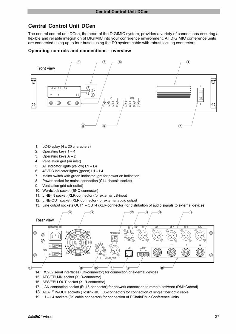
Central Control Unit DCen The central control unit DCen, the heart of the DIGIMIC system, provides a variety of connections ensuring a flexible and reliable integration of DIGIMIC into your conference environment. All DIGIMIC conference units are connected using up to four buses using the D9 system cable with robust locking connectors.
Operating controls and connections - overview
1. LC-Display (4 x 20 characters) 2. Operating keys 1 – 4 3. Operating keys A – D 4. Ventilation grid (air inlet) 5. AF indicator lights (yellow) L1 – L4 6. 48VDC indicator lights (green) L1 – L4 7. Mains switch with green indicator light for power on indication 8. Power socket for mains connection (C14 chassis socket) 9. Ventilation grid (air outlet) 10. Wordclock socket (BNC-connector) 11. LINE-IN socket (XLR-connector) for external LS-input 12. LINE-OUT socket (XLR-connector) for external audio output 13. Line output sockets OUT1 – OUT4 (XLR-connector) for distribution of audio signals to external devices
14. RS232 serial interfaces (C9-connector) for connection of external devices 15. AES/EBU-IN socket (XLR-connector) 16. AES/EBU-OUT socket (XLR-connector) 17. LAN connection socket (RJ45-connector) for network connection to remote software (DMicControl)
18. ADAT® IN/OUT sockets (Toslink JIS F05-connector) for connection of single fiber optic cable 19. L1 – L4 sockets (D9 cable connector) for connection of DChair/DMic Conference Units
Front view
Rear view
5 6 7
41 2 3
12
34
A B C D
9
14 15 16 17 18 19
8 11 1310 12
Central Control Unit DCen
DIGIMIC® wired 28
Operating controls and connections – description
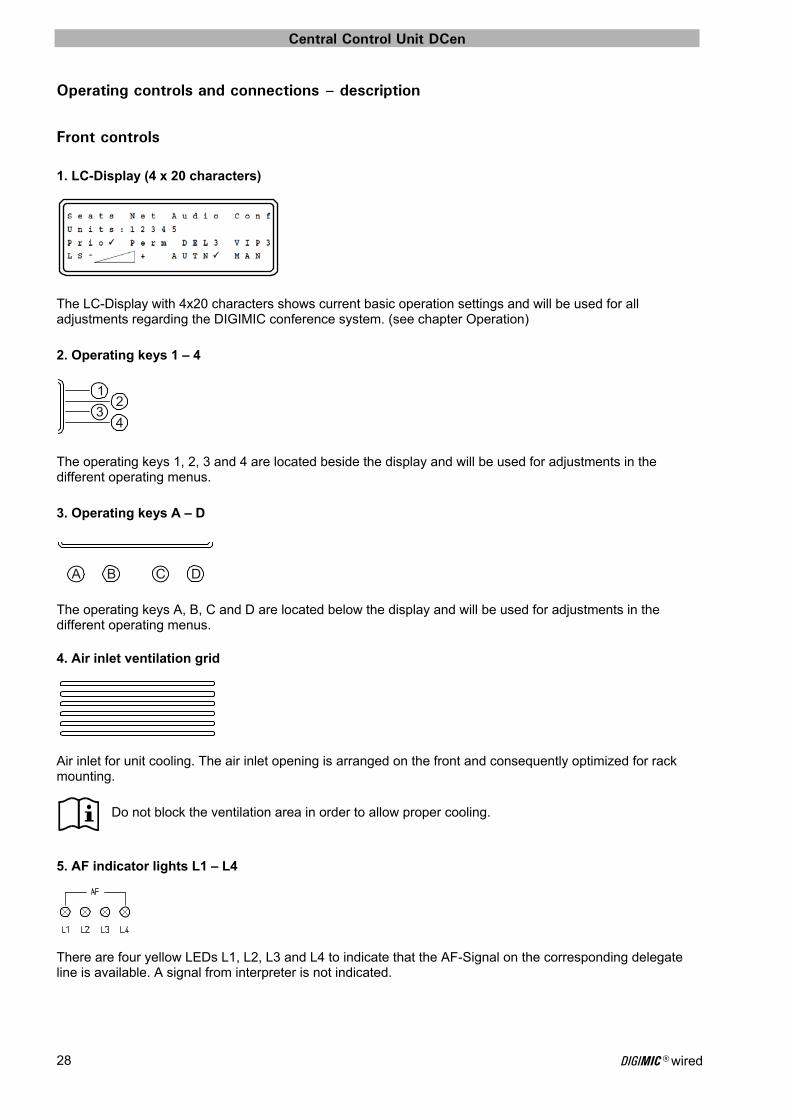
Front controls 1. LC-Display (4 x 20 characters)
The LC-Display with 4x20 characters shows current basic operation settings and will be used for all adjustments regarding the DIGIMIC conference system. (see chapter Operation) 2. Operating keys 1 – 4
The operating keys 1, 2, 3 and 4 are located beside the display and will be used for adjustments in the different operating menus. 3. Operating keys A – D
The operating keys A, B, C and D are located below the display and will be used for adjustments in the different operating menus. 4. Air inlet ventilation grid
Air inlet for unit cooling. The air inlet opening is arranged on the front and consequently optimized for rack mounting.
Do not block the ventilation area in order to allow proper cooling.
5. AF indicator lights L1 – L4
There are four yellow LEDs L1, L2, L3 and L4 to indicate that the AF-Signal on the corresponding delegate line is available. A signal from interpreter is not indicated.
12
34
A B C D
Central Control Unit DCen
DIGIMIC® wired 29
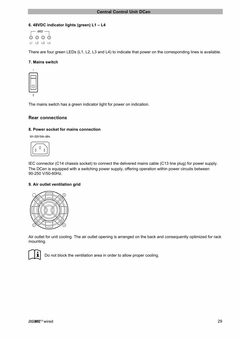
6. 48VDC indicator lights (green) L1 – L4
There are four green LEDs (L1, L2, L3 and L4) to indicate that power on the corresponding lines is available. 7. Mains switch
The mains switch has a green indicator light for power on indication.
Rear connections 8. Power socket for mains connection
IEC connector (C14 chassis socket) to connect the delivered mains cable (C13 line plug) for power supply. The DCen is equipped with a switching power supply, offering operation within power circuits between 90-250 V/50-60Hz. 9. Air outlet ventilation grid
Air outlet for unit cooling. The air outlet opening is arranged on the back and consequently optimized for rack mounting.
Do not block the ventilation area in order to allow proper cooling.

Central Control Unit DCen
DIGIMIC® wired 30
10. Wordclock input socket
The DCen can synchronize to a wordclock feed in here. The wordclock (BNC-connector) is a clock signal used to synchronize multiple devices, such as digital audio tape machines and compact disc players, which interconnect via digital audio. S/PDIF, AES/EBU, ADAT, TDIF and other formats use a word clock.
When using an external wordclock device, please make sure that the crystal accuracy provided by this device has a maximum tolerance of +/- 10ppm and the wordclock provides 48 kHz. Please refer to the manual of your wordclock generating device for more details.
11. LINE-IN socket transformer balanced, +4 dBu
LINE-IN socket (XLR-connector) to feed in external signals for decentralized public address. Each conference unit (DChair and DMic) has incorporated loudspeakers for this purpose. If the original signal is mixed by a mixing console, the signal for the loudspeakers integrated into the conference units must be reconducted from the mixing console to the central control unit. This is done via the LINE-IN socket. 12. LINE-OUT socket transformer balanced, +4 dBu
At the LINE-OUT socket (XLR-connector) you can tap the summarized signal of all conference units that are connected to the system and switched on (combined signal of the LINE output sockets OUT1 – OUT4, see “Default audio routing” on page 22). The audio routing for this output can be altered if desired (please refer to page 51). 13. Line output sockets OUT1 – OUT4 transformer balanced, +4 dBu
To transmit audio signals to external devices there are four LINE outputs (XLR-connector) for connection to an external mixer for recording purposes or to provide a PA system. The audio routing for this output can be altered if desired (please refer to page 51).
Central Control Unit DCen
DIGIMIC® wired 31
14. RS232 serial interfaces
For the connection of external devices there are two RS232 serial communication ports (C9-connector). Both RS-232 outlets carry the same information. 15. AES/EBU-IN socket
Similar as item 11 (LINE-IN socket) but in professional digital format AES/EBU. 16. AES/EBU-OUT socket
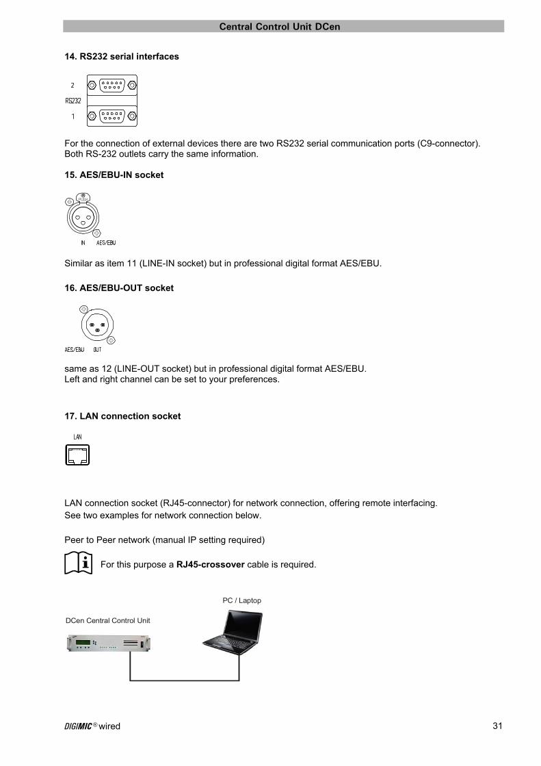
same as 12 (LINE-OUT socket) but in professional digital format AES/EBU. Left and right channel can be set to your preferences. 17. LAN connection socket
LAN connection socket (RJ45-connector) for network connection, offering remote interfacing. See two examples for network connection below. Peer to Peer network (manual IP setting required)
For this purpose a RJ45-crossover cable is required.
DCen Central Control Unit
PC / Laptop
Central Control Unit DCen
DIGIMIC® wired 32
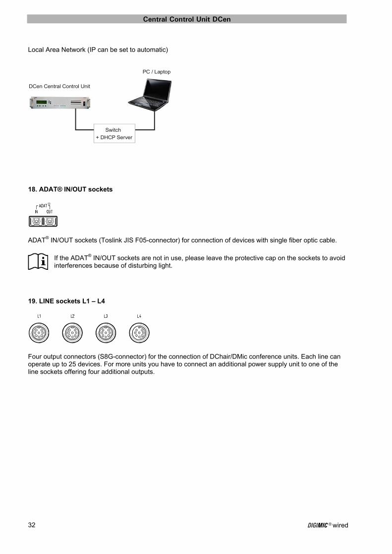
Local Area Network (IP can be set to automatic)
18. ADAT® IN/OUT sockets
ADAT® IN/OUT sockets (Toslink JIS F05-connector) for connection of devices with single fiber optic cable.
If the ADAT® IN/OUT sockets are not in use, please leave the protective cap on the sockets to avoid interferences because of disturbing light.
19. LINE sockets L1 – L4
Four output connectors (S8G-connector) for the connection of DChair/DMic conference units. Each line can operate up to 25 devices. For more units you have to connect an additional power supply unit to one of the line sockets offering four additional outputs.
DCen Central Control Unit
PC / Laptop
Switch
+ DHCP Server

Central Control Unit DCen
DIGIMIC® wired 33
1
2
3
4
DC BA
1
2
3
4
DC B A
Operation
Display and operating buttons The LC-Display with 4x20 characters shows current basic operation settings and will be used for all adjustments regarding the DIGIMIC conference system.
The numbers on the right and the letters below the display denotes the eight buttons, and their position relative to the display. In the following the activity of these buttons are written as follows: • one single button is pressed: 1 to 4 or A to D • one single button is held: 1+ to 4+ or A+ to D+ • one button is held, one button is pressed: 1 to 4 + A to D If in a menu X is shown in the upper right corner of the display this is a „Close-Gadget“: button 1 brings you back to the main menu.
Start-up screen After power up the DCen central control unit, the status display shows the current basic operation settings. The following start-up screen will be shown:
Line 3 shows the FPGA-Version that will be loaded. The progress bar in Line 4 shows the current loading status. If the loading process is done (progress bar completed) the main menu will be shown.
D I G I M I C b y B r ä h l e r
L o a d i n g F P G A # # # #
. . . . . . . . . . . . . .
Central Control Unit DCen
DIGIMIC® wired 34
1
2
3
4
DC B A
1
1
1
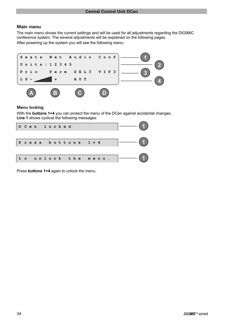
Main menu The main menu shows the current settings and will be used for all adjustments regarding the DIGIMIC conference system. The several adjustments will be explained on the following pages. After powering up the system you will see the following menu:
Menu locking With the buttons 1+4 you can protect the menu of the DCen against accidental changes. Line 1 shows cyclical the following messages:
Press buttons 1+4 again to unlock the menu.
S e a t s N e t A u d i o C o n f
U n i t s : 1 2 3 4 5
P r i o P e r m D E L 3 V I P 3
L S - + A U T
D C e n l o c k e d
P r e s s b u t t o n s 1 + 4
t o u n l o c k t h e m e n u .
Central Control Unit DCen
DIGIMIC® wired 35
1
2
2
2
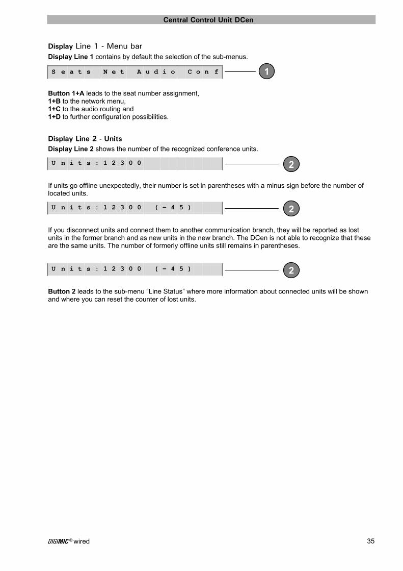
Display Line 1 - Menu bar Display Line 1 contains by default the selection of the sub-menus.
Button 1+A leads to the seat number assignment, 1+B to the network menu, 1+C to the audio routing and 1+D to further configuration possibilities.
Display Line 2 - Units Display Line 2 shows the number of the recognized conference units.
If units go offline unexpectedly, their number is set in parentheses with a minus sign before the number of located units.
If you disconnect units and connect them to another communication branch, they will be reported as lost units in the former branch and as new units in the new branch. The DCen is not able to recognize that these are the same units. The number of formerly offline units still remains in parentheses.
Button 2 leads to the sub-menu “Line Status” where more information about connected units will be shown and where you can reset the counter of lost units.
S e a t s N e t A u d i o C o n f
U n i t s : 1 2 3 0 0
U n i t s : 1 2 3 0 0 ( - 4 5 )
U n i t s : 1 2 3 0 0 ( - 4 5 )
Central Control Unit DCen
DIGIMIC® wired 36
3
4
DC B A
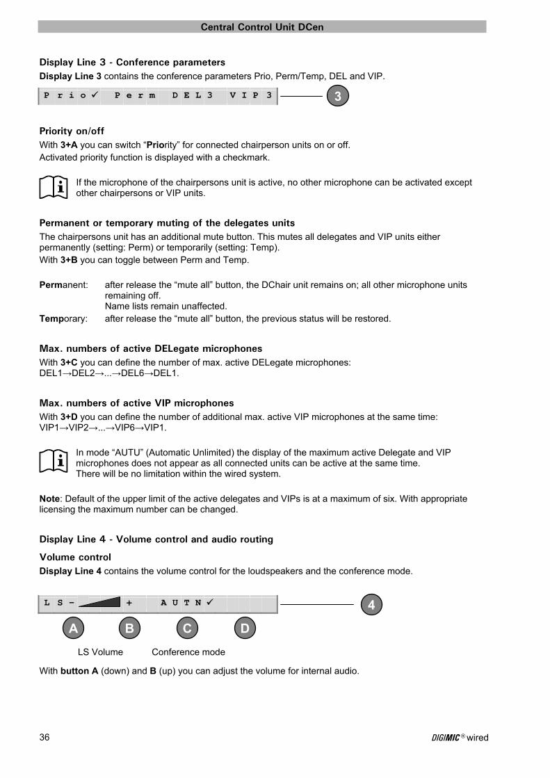
Display Line 3 - Conference parameters Display Line 3 contains the conference parameters Prio, Perm/Temp, DEL and VIP.
Priority on/off With 3+A you can switch “Priority” for connected chairperson units on or off. Activated priority function is displayed with a checkmark.
If the microphone of the chairpersons unit is active, no other microphone can be activated except other chairpersons or VIP units.
Permanent or temporary muting of the delegates units The chairpersons unit has an additional mute button. This mutes all delegates and VIP units either permanently (setting: Perm) or temporarily (setting: Temp). With 3+B you can toggle between Perm and Temp. Permanent: after release the “mute all” button, the DChair unit remains on; all other microphone units remaining off. Name lists remain unaffected. Temporary: after release the “mute all” button, the previous status will be restored.
Max. numbers of active DELegate microphones With 3+C you can define the number of max. active DELegate microphones: DEL1→DEL2→...→DEL6→DEL1.
Max. numbers of active VIP microphones With 3+D you can define the number of additional max. active VIP microphones at the same time: VIP1→VIP2→...→VIP6→VIP1.
In mode “AUTU” (Automatic Unlimited) the display of the maximum active Delegate and VIP microphones does not appear as all connected units can be active at the same time. There will be no limitation within the wired system.
Note: Default of the upper limit of the active delegates and VIPs is at a maximum of six. With appropriate licensing the maximum number can be changed.
Display Line 4 - Volume control and audio routing
Volume control Display Line 4 contains the volume control for the loudspeakers and the conference mode.
With button A (down) and B (up) you can adjust the volume for internal audio.
P r i o P e r m D E L 3 V I P 3
L S - + A U T N
LS Volume Conference mode

Central Control Unit DCen
DIGIMIC® wired 37
4
DC B A
B A
B A
4
DC B A
B A
INTernal or EXTernal audio source Push button 4 to display the choice for the audio source of the loudspeakers (instead of LS and the volume display).
With 4+A and 4+B you can toggle between INTernal and EXTernal audio source. If an internal audio source for the loudspeakers is selected, the menu shows:
INTernal audio source: Audio signal is provided by the DCen central control unit. If an external audio source for the loudspeakers is selected, the menu shows the lettering “LS EXT”. The volume can still be modified with the A and B buttons. With a single press of a button, the volume control is displayed, with further key presses the volume changes accordingly. One second after releasing the buttons, the volume indicator will disappear again.
EXTernal audio source, e.g. mixing console: Audio signal is provided by an external audio source connected via LINE-IN / ADAT or AES/EBU socket (see also chapter Operating controls and connections – description). The LS volume control does not affect the level available at the integrated headphone socket. If the configuration setting "Audio Boost" is activated, there is a small asterisk next to the volume setting.
Network activity Indication about network activity is shown by 2 symbols.
The “.” (dot) will light up when a network cable is connected and connectivity is established.
The “!” (exclamation point) shows network activity (data package transfer), it is flashing. If the DCen is not connected to a network, this field remains blank.
I N T E X T A U T N
L S - +
L S E X T
L S - + *
I N T E X T ! A U T N
Central Control Unit DCen
DIGIMIC® wired 38
4
DC B A
4
DC B A
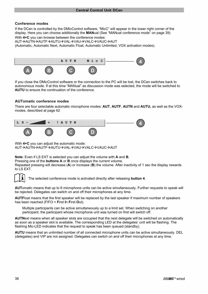
Conference modes If the DCen is controlled by the DMicControl software, “MicC” will appear in the lower right corner of the display. Here you can choose additionally the MANual (See “MANual conference mode” on page 39) With 4+C you can browse between the conference modes: AUTAUTNAUTFAUTUVALVAUVALCVAUCAUT (Automatic, Automatic Next, Automatic Float, Automatic Unlimited, VOX activation modes).
If you close the DMicControl software or the connection to the PC will be lost, the DCen switches back to autonomous mode. If at this time “MANual” as discussion mode was selected, the mode will be switched to AUTU to ensure the continuation of the conference.
AUTomatic conference modes There are four selectable automatic microphone modes: AUT, AUTF, AUTN and AUTU, as well as the VOX-modes, described at page 62
With 4+C you can adjust the automatic mode: AUTAUTNAUTFAUTUVALVAUVALCVAUCAUT Note: Even if LS EXT is selected you can adjust the volume with A and B. Pressing one of the buttons A or B once displays the current volume. Repeated pressing will decrease (A) or increase (B) the volume. After inactivity of 1 sec the display rewards to LS EXT.
The selected conference mode is activated directly after releasing button 4.
AUTomatic means that up to 6 microphone units can be active simultaneously. Further requests to speak will be rejected. Delegates can switch on and off their microphones at any time.
AUTFloat means that the first speaker will be replaced by the last speaker if maximum number of speakers has been reached (FIFO = First In First Out).
Multiple participants can be active simultaneously up to a limit set. When switching on another participant, the participant whose microphone unit was turned on first will switch off.
AUTNext means when all speaker slots are occupied that the next delegate will be switched on automatically as soon as a speaker slot is available. The corresponding LED at the delegates’ unit will be flashing. The flashing Mic-LED indicates that the request to speak has been queued (standby).
AUTU means that an unlimited number of all connected microphone units can be active simultaneously. DEL (delegates) and VIP are not assigned. Delegates can switch on and off their microphones at any time.
A U T N M i c C
L S - + ! A U T N
Central Control Unit DCen
DIGIMIC® wired 39
1
2
3
4
DC BA
2
1
2
3
4
DC B A
MANual conference mode MANualmode cannot be set by the DCEN, but only about a media control or DMicControl software. In this mode delegates can only request to speak, while the chairperson and VIPs can always speak. The microphones will be manually activated from the request list either via DMicControl software or hardware media control. The corresponding microphone button will flash as long as a delegate is in the request list. The delegate can cancel his request at any time by pressing his flashing microphone button again. The delegate can switch off his microphone at any time. When DMicControl is terminated or the media control is switched off, the system fall back to AUTU.
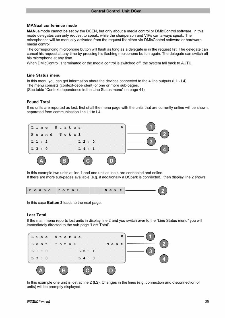
Line Status menu In this menu you can get information about the devices connected to the 4 line outputs (L1 - L4). The menu consists (context-dependent) of one or more sub-pages. (See table “Context dependence in the Line Status menu” on page 41)
Found Total If no units are reported as lost, first of all the menu page with the units that are currently online will be shown, separated from communication line L1 to L4.
In this example two units at line 1 and one unit at line 4 are connected and online. If there are more sub-pages available (e.g. if additionally a DSpark is connected), then display line 2 shows:
In this case Button 2 leads to the next page.
Lost Total If the main menu reports lost units in display line 2 and you switch over to the “Line Status menu” you will immediately directed to the sub-page “Lost Total”.
In this example one unit is lost at line 2 (L2). Changes in the lines (e.g. connection and disconnection of units) will be promptly displayed.
L i n e S t a t u s x
F o u n d T o t a l
L 1 : 2 L 2 : 0
L 3 : 0 L 4 : 1
F o u n d T o t a l N e x t
L i n e S t a t u s x
L o s t T o t a l N e x t
L 1 : 0 L 2 : 1
L 3 : 0 L 4 : 0
Central Control Unit DCen
DIGIMIC® wired 40
1
2
3
4
DC B A
1
2
3
4
DC B A
1
2
3
4
DC B A
1
2
3
4
DC B A
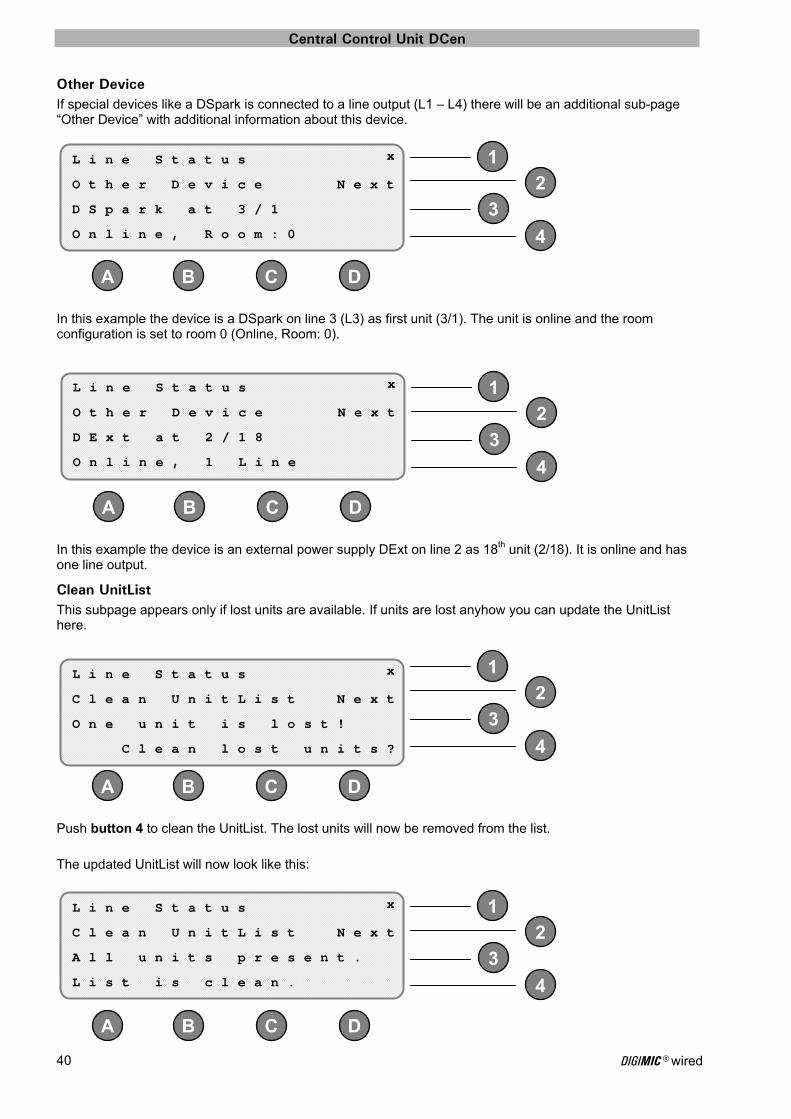
Other Device If special devices like a DSpark is connected to a line output (L1 – L4) there will be an additional sub-page “Other Device” with additional information about this device.
In this example the device is a DSpark on line 3 (L3) as first unit (3/1). The unit is online and the room configuration is set to room 0 (Online, Room: 0).
In this example the device is an external power supply DExt on line 2 as 18th unit (2/18). It is online and has one line output.
Clean UnitList This subpage appears only if lost units are available. If units are lost anyhow you can update the UnitList here.
Push button 4 to clean the UnitList. The lost units will now be removed from the list. The updated UnitList will now look like this:
L i n e S t a t u s x
O t h e r D e v i c e N e x t
D S p a r k a t 3 / 1
O n l i n e , R o o m : 0
L i n e S t a t u s x
O t h e r D e v i c e N e x t
D E x t a t 2 / 1 8
O n l i n e , 1 L i n e
L i n e S t a t u s x
C l e a n U n i t L i s t N e x t
O n e u n i t i s l o s t !
C l e a n l o s t u n i t s ?
L i n e S t a t u s x
C l e a n U n i t L i s t N e x t
A l l u n i t s p r e s e n t .
L i s t i s c l e a n .
Central Control Unit DCen
DIGIMIC® wired 41
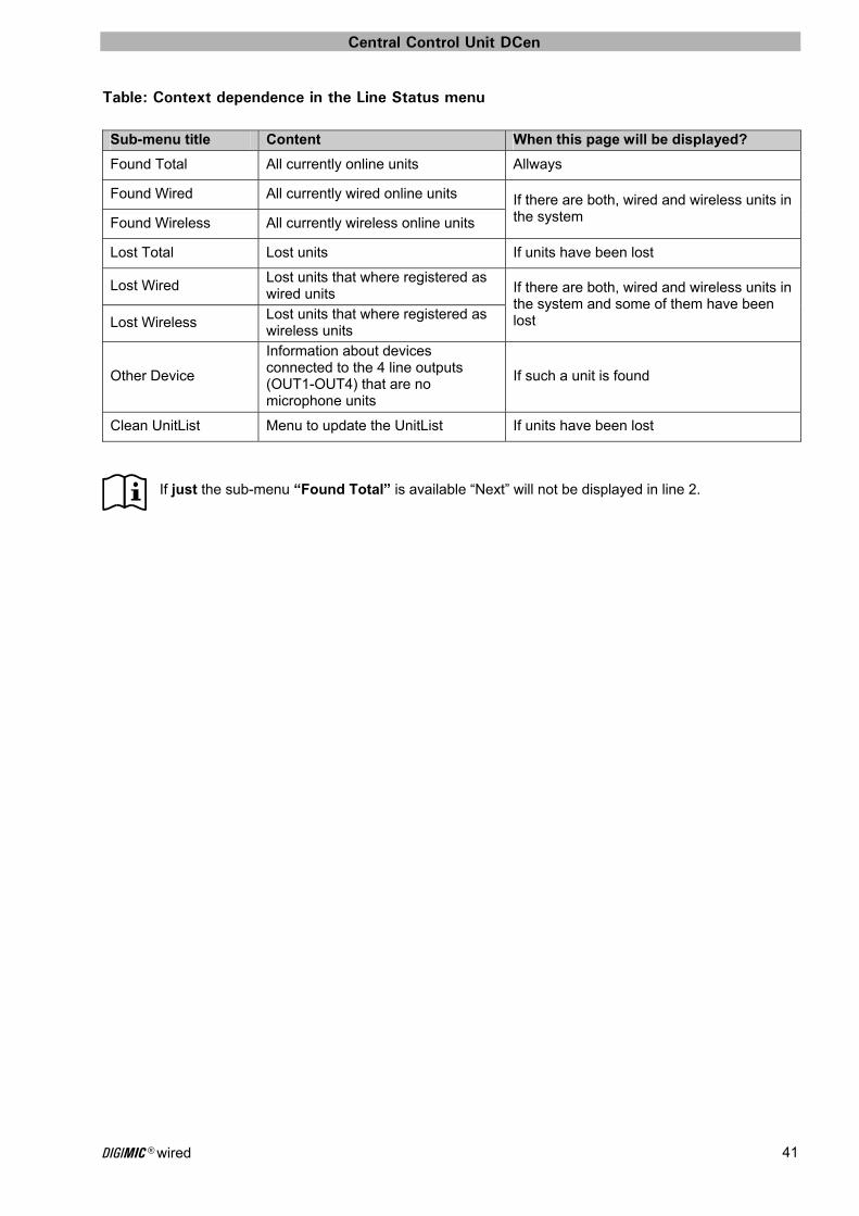
Table: Context dependence in the Line Status menu
Sub-menu title Content When this page will be displayed?
Found Total All currently online units Allways
Found Wired All currently wired online units If there are both, wired and wireless units in the system Found Wireless All currently wireless online units
Lost Total Lost units If units have been lost
Lost Wired Lost units that where registered as wired units If there are both, wired and wireless units in
the system and some of them have been lost Lost Wireless
Lost units that where registered as wireless units
Other Device
Information about devices connected to the 4 line outputs (OUT1-OUT4) that are no microphone units
If such a unit is found
Clean UnitList Menu to update the UnitList If units have been lost
If just the sub-menu “Found Total” is available “Next” will not be displayed in line 2.
Central Control Unit DCen
DIGIMIC® wired 42
1
2
3
4
DC B A
1
2
3
4
DC B A
4
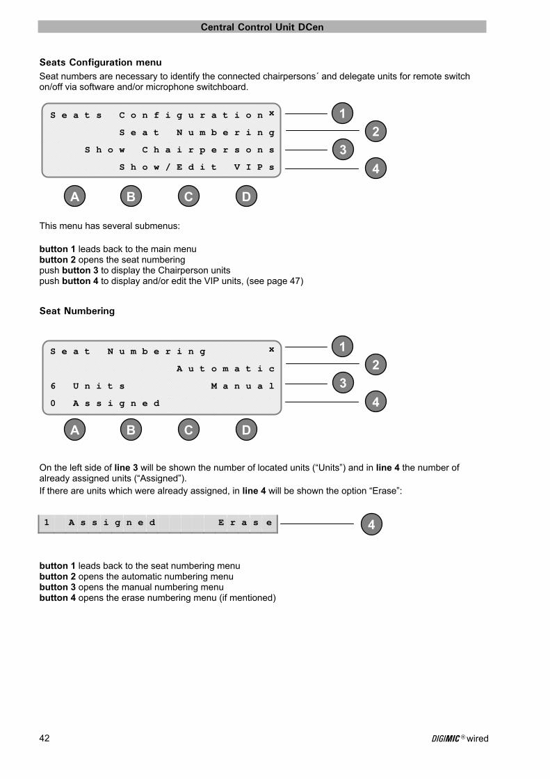
Seats Configuration menu Seat numbers are necessary to identify the connected chairpersons´ and delegate units for remote switch on/off via software and/or microphone switchboard.
This menu has several submenus: button 1 leads back to the main menu button 2 opens the seat numbering push button 3 to display the Chairperson units push button 4 to display and/or edit the VIP units, (see page 47)
Seat Numbering
On the left side of line 3 will be shown the number of located units (“Units”) and in line 4 the number of already assigned units (“Assigned”). If there are units which were already assigned, in line 4 will be shown the option “Erase”:
button 1 leads back to the seat numbering menu button 2 opens the automatic numbering menu button 3 opens the manual numbering menu button 4 opens the erase numbering menu (if mentioned)
S e a t s C o n f i g u r a t i o n x
S e a t N u m b e r i n g
S h o w C h a i r p e r s o n s
S h o w / E d i t V I P s
S e a t N u m b e r i n g x
A u t o m a t i c
6 U n i t s M a n u a l
0 A s s i g n e d
1 A s s i g n e d E r a s e
Central Control Unit DCen
DIGIMIC® wired 43
1
2
3
4
DC BA
DC B A
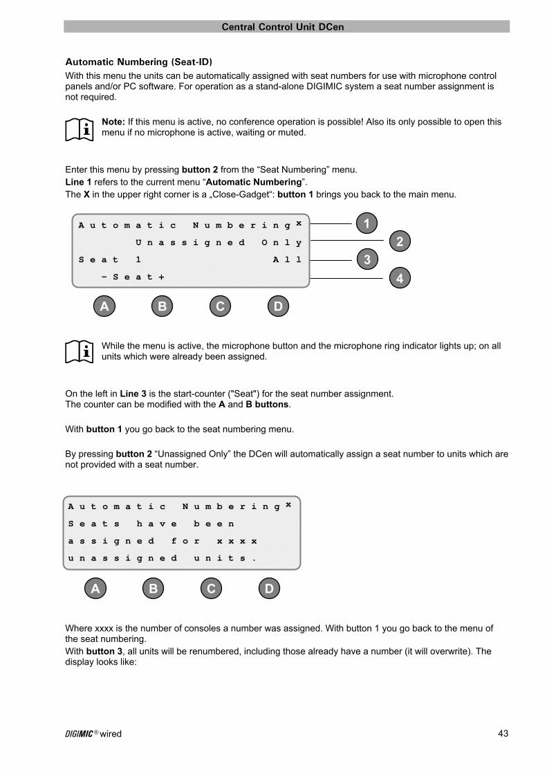
Automatic Numbering (Seat-ID) With this menu the units can be automatically assigned with seat numbers for use with microphone control panels and/or PC software. For operation as a stand-alone DIGIMIC system a seat number assignment is not required.
Note: If this menu is active, no conference operation is possible! Also its only possible to open this menu if no microphone is active, waiting or muted.
Enter this menu by pressing button 2 from the “Seat Numbering” menu. Line 1 refers to the current menu “Automatic Numbering”. The X in the upper right corner is a „Close-Gadget“: button 1 brings you back to the main menu.
While the menu is active, the microphone button and the microphone ring indicator lights up; on all units which were already been assigned.
On the left in Line 3 is the start-counter ("Seat") for the seat number assignment. The counter can be modified with the A and B buttons. With button 1 you go back to the seat numbering menu. By pressing button 2 “Unassigned Only” the DCen will automatically assign a seat number to units which are not provided with a seat number.
Where xxxx is the number of consoles a number was assigned. With button 1 you go back to the menu of the seat numbering. With button 3, all units will be renumbered, including those already have a number (it will overwrite). The display looks like:
A u t o m a t i c N u m b e r i n g x
U n a s s i g n e d O n l y
S e a t 1 A l l
- S e a t +
A u t o m a t i c N u m b e r i n g x
S e a t s h a v e b e e n
a s s i g n e d f o r x x x x
u n a s s i g n e d u n i t s .
Central Control Unit DCen
DIGIMIC® wired 44
1
2
3
4
DC B A
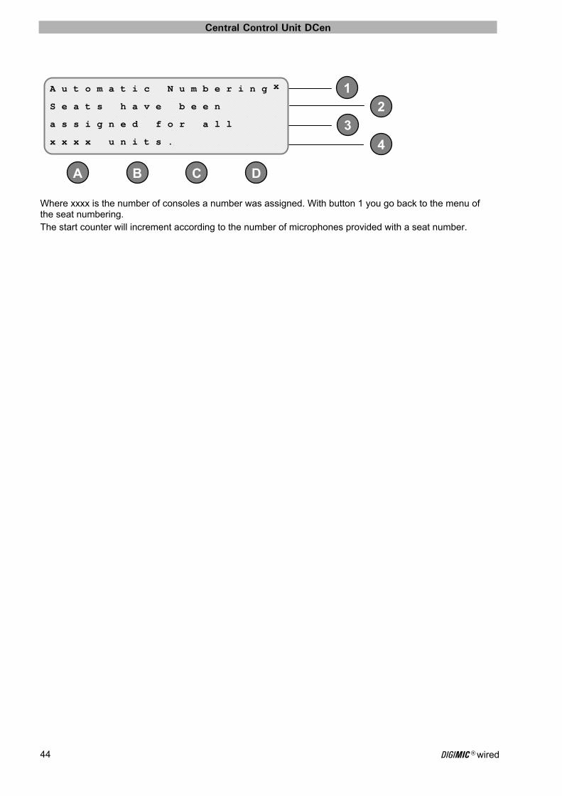
Where xxxx is the number of consoles a number was assigned. With button 1 you go back to the menu of the seat numbering. The start counter will increment according to the number of microphones provided with a seat number.
A u t o m a t i c N u m b e r i n g x
S e a t s h a v e b e e n
a s s i g n e d f o r a l l
x x x x u n i t s .

Central Control Unit DCen
DIGIMIC® wired 45
12
3
4
DC BA
3
3
Manual Numbering (Seat-ID) With this menu the units can be assigned with seat numbers for use with microphone control panels and/or PC software or to specify a certain area of the conference room with manually assigned seat numbers, e.g. stage. For operation as a stand-alone DIGIMIC system a number assignment is not required.
Note: If this menu is active, no conference operation is possible! Also its only possible to open this menu if no microphone is active, waiting or muted.
Enter this menu by pressing button 3 from the “Seat Numbering” menu. Line 1 refers to the current menu “Manual Numbering”. The X in the upper right corner is a „Close-Gadget“: button 1 brings you back to the main menu.
As long as this menu is activated all units which are already assigned with a microphone seat number show the microphone ring indicator in “on”-function. The first unassigned unit shows a flashing indicator, the so-called “cursor”. On the left in Line 3 is the start-counter („Seat") for the seat number assignment. The counter can be modified with the A and B buttons. The unit for numbering can be selected with the buttons C and D. A seat number can be assigned now either by pushing the corresponding MIC-button on the unit or with the Assign-button (button 2).
The position of the flashing ring indicator light changes accordingly to the selected unit, to show the room position, operating as a flashing cursor.
If you assign the current selected unit with the next seat number, the flashing ring indicator light changes accordingly to the selected unit and the next number to be assigned is increased by one. At the unit, which a seat number was assigned, the Mic LED now lights up as a sign that it has been assigned with a number. If you select a unit which has already been assigned a seat number, then this is shown in Line 3 on the right in square brackets:
With button 3, the assignment can be undone:
Example: Unit 1/1 indicates the first unit connected to D9-Line #1 (L1). Unit 4/15 indicates the 15th unit connected to D9-Line #4 (L4).
M a n u a l N u m b e r i n g x
S e a t 1 A s s i g n
U n i t 1 / 1 [ N o n e ]
- S e a t + - U n i t +
U n i t 1 / 1 [ 1 ]
U n i t 1 / 1 [ N o n e ]
Central Control Unit DCen
DIGIMIC® wired 46
1
2
3
4
DC B A
1
2
3
4
DC B A
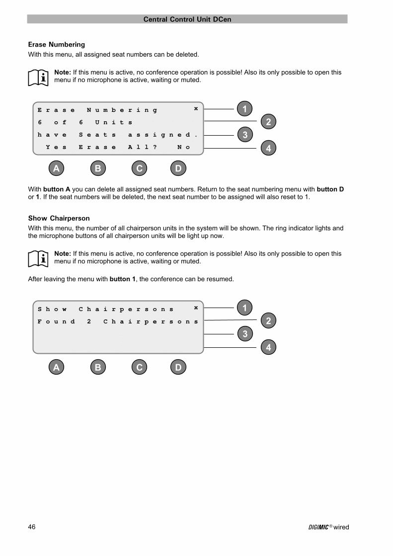
Erase Numbering With this menu, all assigned seat numbers can be deleted.
Note: If this menu is active, no conference operation is possible! Also its only possible to open this menu if no microphone is active, waiting or muted.
With button A you can delete all assigned seat numbers. Return to the seat numbering menu with button D or 1. If the seat numbers will be deleted, the next seat number to be assigned will also reset to 1.
Show Chairperson With this menu, the number of all chairperson units in the system will be shown. The ring indicator lights and the microphone buttons of all chairperson units will be light up now.
Note: If this menu is active, no conference operation is possible! Also its only possible to open this menu if no microphone is active, waiting or muted.
After leaving the menu with button 1, the conference can be resumed.
E r a s e N u m b e r i n g x
6 o f 6 U n i t s
h a v e S e a t s a s s i g n e d .
Y e s E r a s e A l l ? N o
S h o w C h a i r p e r s o n s x
F o u n d 2 C h a i r p e r s o n s

Central Control Unit DCen
DIGIMIC® wired 47
1
2
3
4
DC BA
2
2
2
Show/Edit VIPs With this menu, the number of all VIP units in the system will be shown. The ring indicator lights and the microphone buttons of all these units will be light up now.
Note: If this menu is active, no conference operation is possible! Also its only possible to open this menu if no microphone is active, waiting or muted.
A change in the VIP status is available either via the microphone button on the units as well as from the menu. Line 1 refers to the current menu “Show/Edit VIPs”. The X in the upper right corner is a „Close-Gadget“: button 1 brings you back to the main menu.
As long as the menu is active, the microphone ring works as a "cursor" symbol: A VIP-unit whose position is described in Line 4 („Unit"), has a blinking LED ring. With the buttons C and D, the cursor will be moved down (smaller units and / or line number) and upward (larger units and / or line number). The adequate selection will be shown in Line 2: If the selected unit is not a VIP-unit, you can switch over to a VIP-unit with button 2.
If the selected unit is a VIP-unit, you can switch over to a non VIP-unit with button 2.
If the selected unit is a chairperson unit, this status will be shown in Line 2, and is not changeable. A chairperson cannot be assigned a VIP status.
The status of the units will be displayed also by the microphone button and ring indicator lights:
Ring indicator and microphone button off: No VIP. Ring indicator and microphone button on: VIP. Ring indicator flashes and microphone button off: This unit is selected in the menu (cursor) and is
not a VIP-unit. Ring indicator flashes and microphone button on: This unit is selected in the menu (the cursor) and
is a VIP-unit. Additionally to the setting procedure with the menu, the status can be changed at the unit on site while the menu is active. The current status can be switched over by pressing the microphone button, then the cursor will be also placed on this unit. To change the status of a DChair unit is of course not possible.
S h o w / E d i t V I P s x
A d d V I P S t a t u s
F o u n d 0 V I P s
U n i t 1 / 1 - U n i t +
A d d V I P S t a t u s
R e m o v e V I P S t a t u s
( C h a i r p e r s o n )
Central Control Unit DCen
DIGIMIC® wired 48
1
2
3
4
DC B A
4
DC B A
23
Networking menu The default network setting is „Dynamic“, where the DCen central control unit receives all necessary settings automatically from a DHCP-server on the network.
The networking menu is spread over seven pages.
Line 1 shows the current menu “Networking”. The X in the upper right corner is a „Close-Gadget“: button 1 brings you back to the main menu. The menu title and the possibility to go back to the main menu is the same on all pages. With button 2 you can scroll through the parameter pages. The right side of Line 4 shows the current status dynamic or static. With button 4 you can toggle between Dynamic (automatic) and Static (manual) address assignment.
Static and dynamic address assignment With button 4 you can toggle between Dynamic (automatic) and Static (manual) address assignment. Use “Dynamic” if the DCen central control unit is connected to a DHCP network which can provide the necessarily network settings (e.g. IP-address, In-house-net) Use “Static” if the DCen central control unit is connected to a network without a DHCP server (e.g. Peer to Peer network, PC directly with crossover cable) entering the necessary values manually.
During changeover from Static to Dynamic address assignment there may be a few seconds delay until a server is found and the address is assigned. During this time, as address 0.0.0.0 is displayed. If this setting hasn’t changed after a few seconds to a valid address, no DHCP server is available in the network or refuses to provide the DCen address allocation.
Networking parameters The networking menu consists of seven pages with the following indications and parameters:
TCP/IP Address This is the IPV4-address of the DCen central control unit.
In this sample it is the dynamic address assigned from the DHCP-Server. This can be seen that besides the button 3 "Edit" does not appear.
N e t w o r k i n g x
T C P / I P A d d r e s s N e x t
1 0 . 0 . 1 . 7
1 0 0 F D D y n a m i c
D y n a m i c
T C P / I P A d d r e s s N e x t
1 0 . 0 . 1 . 7
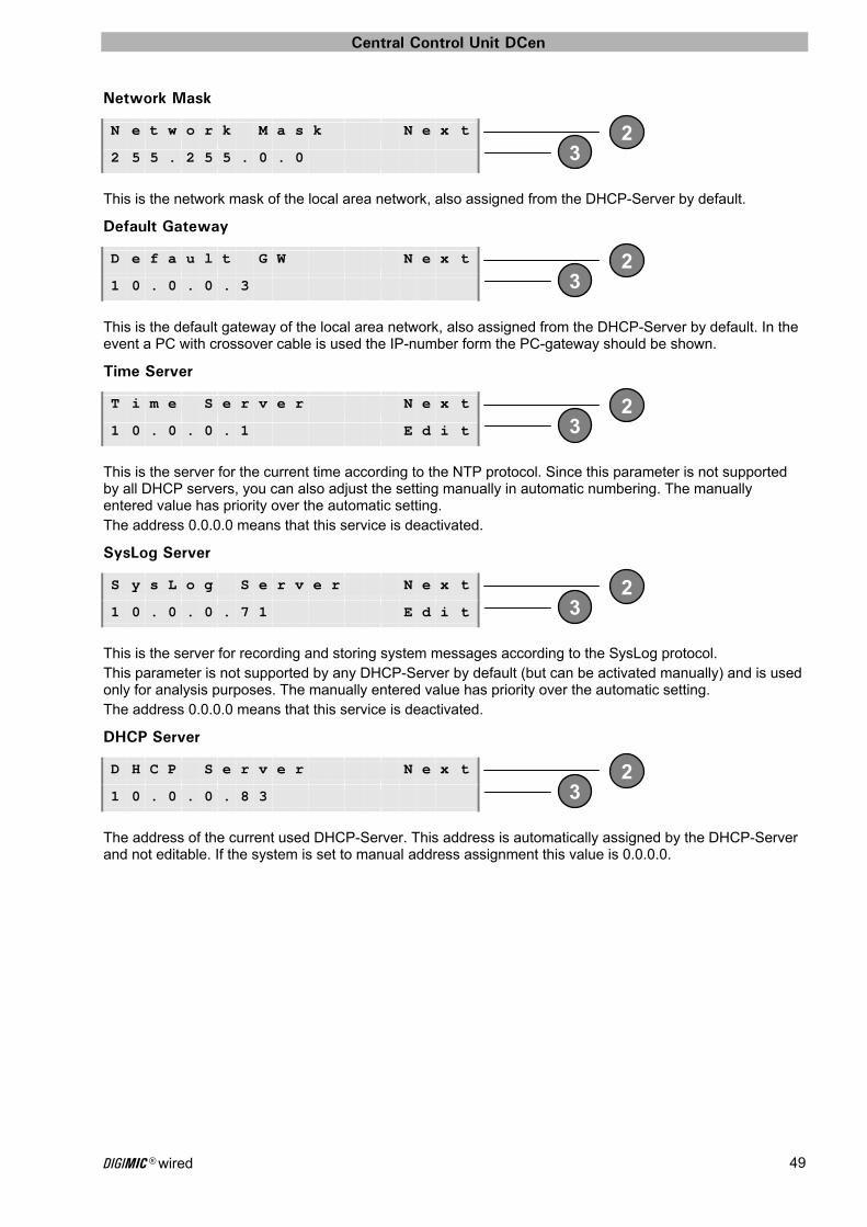
Central Control Unit DCen
DIGIMIC® wired 49
2 3
2 3
2 3
2 3
2 3
Network Mask
This is the network mask of the local area network, also assigned from the DHCP-Server by default.
Default Gateway
This is the default gateway of the local area network, also assigned from the DHCP-Server by default. In the event a PC with crossover cable is used the IP-number form the PC-gateway should be shown.
Time Server
This is the server for the current time according to the NTP protocol. Since this parameter is not supported by all DHCP servers, you can also adjust the setting manually in automatic numbering. The manually entered value has priority over the automatic setting. The address 0.0.0.0 means that this service is deactivated.
SysLog Server
This is the server for recording and storing system messages according to the SysLog protocol. This parameter is not supported by any DHCP-Server by default (but can be activated manually) and is used only for analysis purposes. The manually entered value has priority over the automatic setting. The address 0.0.0.0 means that this service is deactivated.
DHCP Server
The address of the current used DHCP-Server. This address is automatically assigned by the DHCP-Server and not editable. If the system is set to manual address assignment this value is 0.0.0.0.
N e t w o r k M a s k N e x t
2 5 5 . 2 5 5 . 0 . 0
D e f a u l t G W N e x t
1 0 . 0 . 0 . 3
T i m e S e r v e r N e x t
1 0 . 0 . 0 . 1 E d i t
S y s L o g S e r v e r N e x t
1 0 . 0 . 0 . 7 1 E d i t
D H C P S e r v e r N e x t
1 0 . 0 . 0 . 8 3
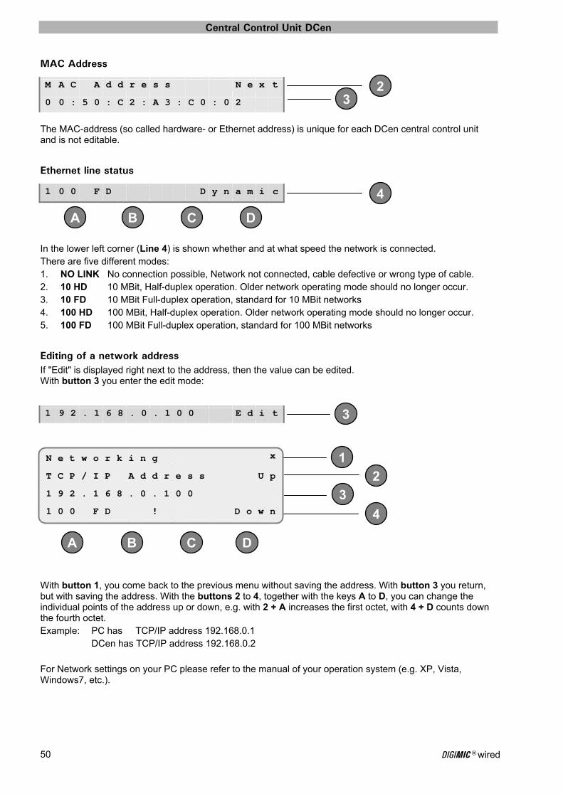
Central Control Unit DCen
DIGIMIC® wired 50
23
4
DC B A
3
1
2
3
4
DC B A
MAC Address
The MAC-address (so called hardware- or Ethernet address) is unique for each DCen central control unit and is not editable.
Ethernet line status
In the lower left corner (Line 4) is shown whether and at what speed the network is connected. There are five different modes: 1. NO LINK No connection possible, Network not connected, cable defective or wrong type of cable. 2. 10 HD 10 MBit, Half-duplex operation. Older network operating mode should no longer occur. 3. 10 FD 10 MBit Full-duplex operation, standard for 10 MBit networks 4. 100 HD 100 MBit, Half-duplex operation. Older network operating mode should no longer occur. 5. 100 FD 100 MBit Full-duplex operation, standard for 100 MBit networks
Editing of a network address If "Edit" is displayed right next to the address, then the value can be edited. With button 3 you enter the edit mode:
With button 1, you come back to the previous menu without saving the address. With button 3 you return, but with saving the address. With the buttons 2 to 4, together with the keys A to D, you can change the individual points of the address up or down, e.g. with 2 + A increases the first octet, with 4 + D counts down the fourth octet. Example: PC has TCP/IP address 192.168.0.1 DCen has TCP/IP address 192.168.0.2 For Network settings on your PC please refer to the manual of your operation system (e.g. XP, Vista, Windows7, etc.).
M A C A d d r e s s N e x t
0 0 : 5 0 : C 2 : A 3 : C 0 : 0 2
1 0 0 F D D y n a m i c
1 9 2 . 1 6 8 . 0 . 1 0 0 E d i t
N e t w o r k i n g x
T C P / I P A d d r e s s U p
1 9 2 . 1 6 8 . 0 . 1 0 0
1 0 0 F D ! D o w n
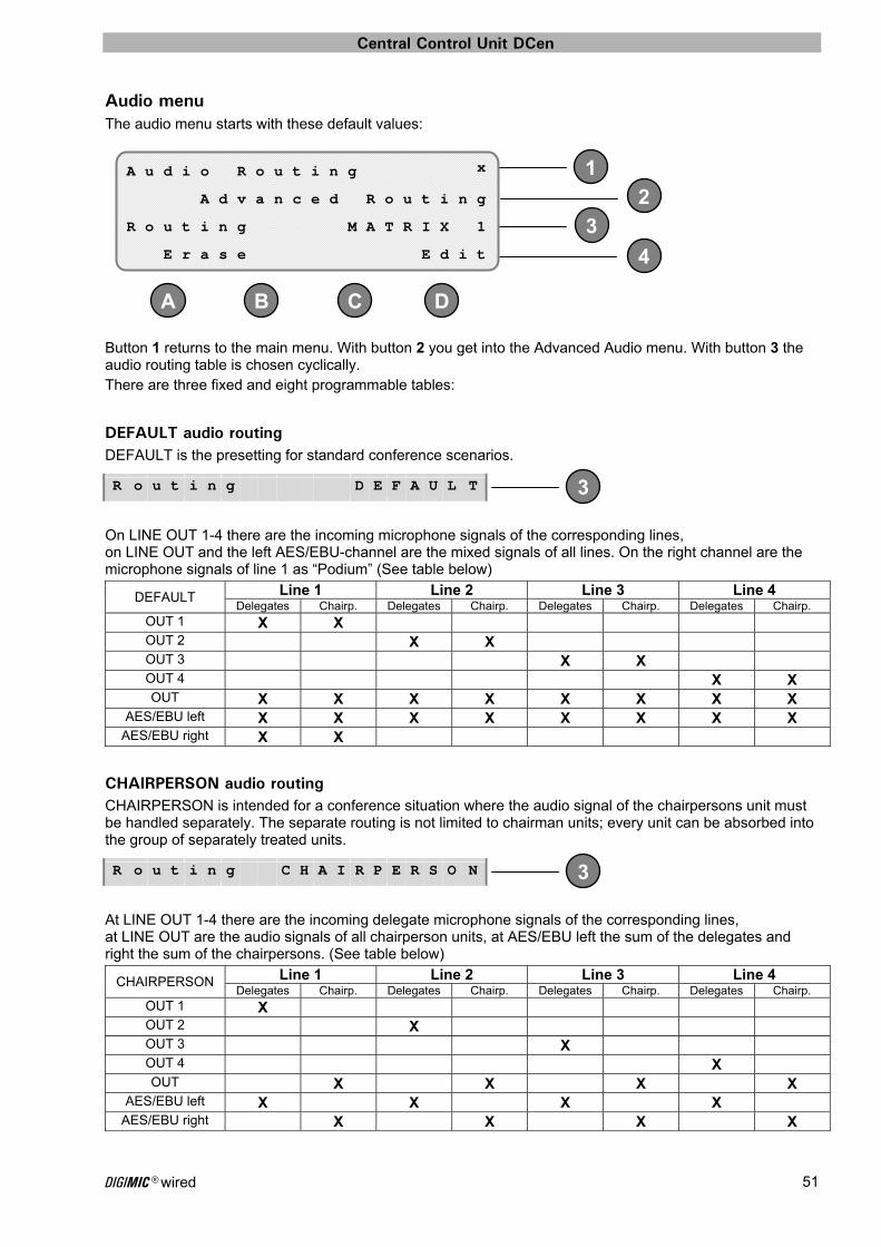
Central Control Unit DCen
DIGIMIC® wired 51
1
2
3
4
DC BA
3
3
Audio menu The audio menu starts with these default values:
Button 1 returns to the main menu. With button 2 you get into the Advanced Audio menu. With button 3 the audio routing table is chosen cyclically. There are three fixed and eight programmable tables:
DEFAULT audio routing DEFAULT is the presetting for standard conference scenarios.
On LINE OUT 1-4 there are the incoming microphone signals of the corresponding lines, on LINE OUT and the left AES/EBU-channel are the mixed signals of all lines. On the right channel are the microphone signals of line 1 as “Podium” (See table below)
DEFAULT Line 1 Line 2 Line 3 Line 4 Delegates Chairp. Delegates Chairp. Delegates Chairp. Delegates Chairp.
OUT 1 X X OUT 2 X X OUT 3 X X OUT 4 X X OUT X X X X X X X X
AES/EBU left X X X X X X X X AES/EBU right X X
CHAIRPERSON audio routing CHAIRPERSON is intended for a conference situation where the audio signal of the chairpersons unit must be handled separately. The separate routing is not limited to chairman units; every unit can be absorbed into the group of separately treated units.
At LINE OUT 1-4 there are the incoming delegate microphone signals of the corresponding lines, at LINE OUT are the audio signals of all chairperson units, at AES/EBU left the sum of the delegates and right the sum of the chairpersons. (See table below)
CHAIRPERSON Line 1 Line 2 Line 3 Line 4 Delegates Chairp. Delegates Chairp. Delegates Chairp. Delegates Chairp.
OUT 1 X OUT 2 X OUT 3 X OUT 4 X OUT X X X X
AES/EBU left X X X X AES/EBU right X X X X
A u d i o R o u t i n g x
A d v a n c e d R o u t i n g
R o u t i n g M A T R I X 1
E r a s e E d i t
R o u t i n g D E F A U L T
R o u t i n g C H A I R P E R S O N
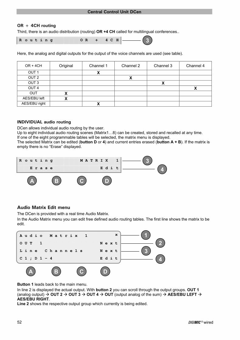
Central Control Unit DCen
DIGIMIC® wired 52
4
DC B A
3
1
2
3
4
DC B A
3
OR + 4CH routing Third, there is an audio distribution (routing) OR +4 CH called for multilingual conferences..
Here, the analog and digital outputs for the output of the voice channels are used (see table).
OR + 4CH Original Channel 1 Channel 2 Channel 3 Channel 4
OUT 1 X OUT 2 X OUT 3 X OUT 4 X OUT X
AES/EBU left X AES/EBU right X
INDIVIDUAL audio routing DCen allows individual audio routing by the user. Up to eight individual audio routing scenes (Matrix1…8) can be created, stored and recalled at any time. If one of the eight programmable tables will be selected, the matrix menu is displayed. The selected Matrix can be edited (button D or 4) and current entries erased (button A + B). If the matrix is empty there is no “Erase” displayed.
Audio Matrix Edit menu The DCen is provided with a real time Audio Matrix. In the Audio Matrix menu you can edit free defined audio routing tables. The first line shows the matrix to be edit.
Button 1 leads back to the main menu. In line 2 is displayed the actual output. With button 2 you can scroll through the output groups. OUT 1 (analog output) OUT 2 OUT 3 OUT 4 OUT (output analog of the sum) AES/EBU LEFT AES/EBU RIGHT. Line 2 shows the respective output group which currently is being edited.
R o u t i n g O R + 4 C H
R o u t i n g M A T R I X 1
E r a s e E d i t
A u d i o M a t r i x 1 x
O U T 1 N e x t
L i n e C h a n n e l s N e x t
C 1 ; D 1 - 4 E d i t
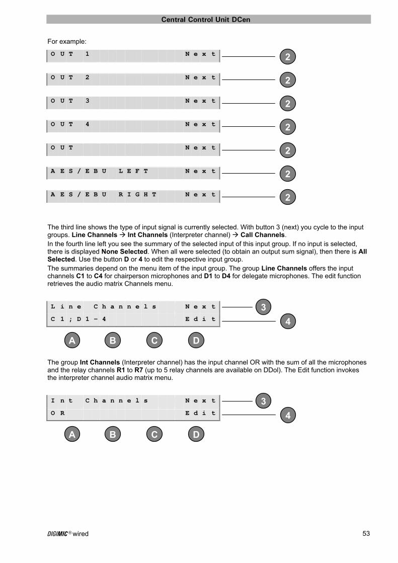
Central Control Unit DCen
DIGIMIC® wired 53
2
2
2
2
2
2
2
4
DC B A
3
4
DC B A
3
For example:
The third line shows the type of input signal is currently selected. With button 3 (next) you cycle to the input groups. Line Channels Int Channels (Interpreter channel) Call Channels. In the fourth line left you see the summary of the selected input of this input group. If no input is selected, there is displayed None Selected. When all were selected (to obtain an output sum signal), then there is All Selected. Use the button D or 4 to edit the respective input group. The summaries depend on the menu item of the input group. The group Line Channels offers the input channels C1 to C4 for chairperson microphones and D1 to D4 for delegate microphones. The edit function retrieves the audio matrix Channels menu.
The group Int Channels (Interpreter channel) has the input channel OR with the sum of all the microphones and the relay channels R1 to R7 (up to 5 relay channels are available on DDol). The Edit function invokes the interpreter channel audio matrix menu.
O U T 1 N e x t
O U T 2 N e x t
O U T 3 N e x t
O U T 4 N e x t
O U T N e x t
A E S / E B U L E F T N e x t
A E S / E B U R I G H T N e x t
L i n e C h a n n e l s N e x t
C 1 ; D 1 - 4 E d i t
I n t C h a n n e l s N e x t
O R E d i t
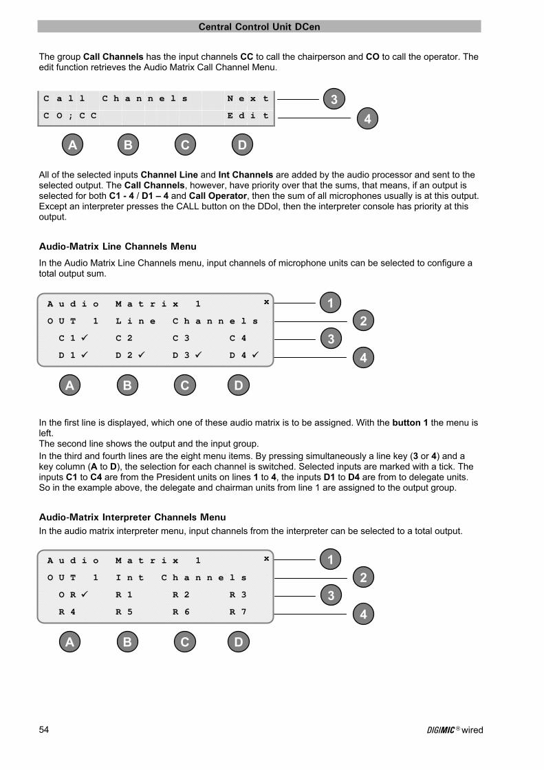
Central Control Unit DCen
DIGIMIC® wired 54
4
DC B A
3
1
2
3
4
DC B A
1
2
3
4
DC B A
The group Call Channels has the input channels CC to call the chairperson and CO to call the operator. The edit function retrieves the Audio Matrix Call Channel Menu.
All of the selected inputs Channel Line and Int Channels are added by the audio processor and sent to the selected output. The Call Channels, however, have priority over that the sums, that means, if an output is selected for both C1 - 4 / D1 – 4 and Call Operator, then the sum of all microphones usually is at this output. Except an interpreter presses the CALL button on the DDol, then the interpreter console has priority at this output.
Audio-Matrix Line Channels Menu
In the Audio Matrix Line Channels menu, input channels of microphone units can be selected to configure a total output sum.
In the first line is displayed, which one of these audio matrix is to be assigned. With the button 1 the menu is left. The second line shows the output and the input group. In the third and fourth lines are the eight menu items. By pressing simultaneously a line key (3 or 4) and a key column (A to D), the selection for each channel is switched. Selected inputs are marked with a tick. The inputs C1 to C4 are from the President units on lines 1 to 4, the inputs D1 to D4 are from to delegate units. So in the example above, the delegate and chairman units from line 1 are assigned to the output group.
Audio-Matrix Interpreter Channels Menu In the audio matrix interpreter menu, input channels from the interpreter can be selected to a total output.
C a l l C h a n n e l s N e x t
C O ; C C E d i t
A u d i o M a t r i x 1 x
O U T 1 L i n e C h a n n e l s
C 1 C 2 C 3 C 4
D 1 D 2 D 3 D 4
A u d i o M a t r i x 1 x
O U T 1 I n t C h a n n e l s
O R R 1 R 2 R 3
R 4 R 5 R 6 R 7
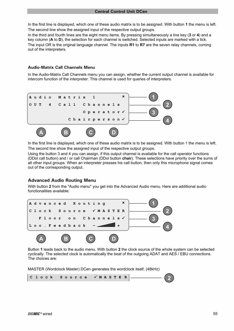
Central Control Unit DCen
DIGIMIC® wired 55
1
2
3
4
DC B A
1
2
3
4
DC B A
2
In the first line is displayed, which one of these audio matrix is to be assigned. With button 1 the menu is left. The second line show the assigned input of the respective output groups. In the third and fourth lines are the eight menu items. By pressing simultaneously a line key (3 or 4) and a key column (A to D), the selection for each channel is switched. Selected inputs are marked with a tick. The input OR is the original language channel. The inputs R1 to R7 are the seven relay channels, coming out of the interpreters.
Audio-Matrix Call Channels Menu
In the Audio-Matrix Call Channels menu you can assign, whether the current output channel is available for intercom function of the interpreter. This channel is used for queries of interpreters.
In the first line is displayed, which one of these audio matrix is to be assigned. With button 1 the menu is left. The second line show the assigned input of the respective output groups. Using the button 3 and 4 you can assign, if this output channel is available for the call operator functions (DDol call button) and / or call Chairman (DDol button chair). These selections have priority over the sums of all other input groups. When an interpreter presses his call button, then only this microphone signal comes out of the corresponding output.
Advanced Audio Routing Menu With button 2 from the "Audio menu" you get into the Advanced Audio menu. Here are additional audio functionalities available:
Button 1 leads back to the audio menu. With button 2 the clock source of the whole system can be selected cyclically. The selected clock is automatically the beat of the outgoing ADAT and AES / EBU connections. The choices are: MASTER (Wordclock Master) DCen generates the wordclock itself, (48kHz)
A u d i o M a t r i x 1 x
O U T 4 C a l l C h a n n e l s
O p e r a t o r
C h a i r p e r s o n
A d v a n c e d R o u t i n g x
C l o c k S o u r c e M A S T E R
F l o o r o n C h a n n e l s
L o c . F e e d b a c k - +
C l o c k S o u r c e M A S T E R

Central Control Unit DCen
DIGIMIC® wired 56
2
2
2
EXTERN (Wordclock Slave) Clock is located at the port „WORDCLOCK in“
ADAT (Wordclock Slave) Clock is fed from the ADAT signal
AES/EBU (Wordclock Slave) Clock will take over from the incoming AES/EBU signal
If the clock source has been detected, and is within the specified limits, a check mark appears before the name of the clock source. If the selected clock source failed or the delivered frequency is outside the specified limits, the DCen continues working with the internal master clock without interruption. Pressing button 3 you can switch on the "Floor on channels" option. If it is enabled, outputs with non-active interpretation channel in the routing will transfer the floor signal (the original). This is e.g. important when a signal is sent to a language distribution (INFRACOM). For other purposes such as media distribution, an original (floor) signal on not active interpretation channel is undesirable. In the fourth line, the local microphone feedback can be adjusted. This is important if two DCen are coupled via ADAT. Example: one of the DCEN is connected to the interpreter units and the other DCen is used for the delegate units. In this case you have to connect both via ADAT and set to "external". The feedback level of the DCEN with the delegate units is set to maximum. The level of the feedback can be controlled with the buttons C and D.
When using an external wordclock device, please make sure that the sample rate (clock frequency) is 48 kHz and the crystal accuracy provided by the external device has a maximum tolerance of +/- 10ppm.
C l o c k S o u r c e E X T E R N
C l o c k S o u r c e A D A T
C l o c k S o u r c e A E S E B U
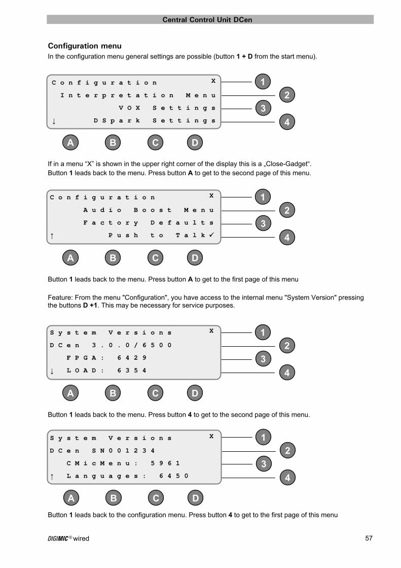
Central Control Unit DCen
DIGIMIC® wired 57
1
2
3
4
DC B A
1
2
3
4
DC B A
12
3
4
DC B A
12
3
4
DC B A
Configuration menu In the configuration menu general settings are possible (button 1 + D from the start menu).
If in a menu “X” is shown in the upper right corner of the display this is a „Close-Gadget“. Button 1 leads back to the menu. Press button A to get to the second page of this menu.
Button 1 leads back to the menu. Press button A to get to the first page of this menu Feature: From the menu "Configuration", you have access to the internal menu "System Version" pressing the buttons D +1. This may be necessary for service purposes.
Button 1 leads back to the menu. Press button 4 to get to the second page of this menu.
Button 1 leads back to the configuration menu. Press button 4 to get to the first page of this menu
C o n f i g u r a t i o n X
I n t e r p r e t a t i o n M e n u
V O X S e t t i n g s
↓ D S p a r k S e t t i n g s
C o n f i g u r a t i o n X
A u d i o B o o s t M e n u
F a c t o r y D e f a u l t s
↑ P u s h t o T a l k
S y s t e m V e r s i o n s X
D C e n 3 . 0 . 0 / 6 5 0 0
F P G A : 6 4 2 9
↓ L O A D : 6 3 5 4
S y s t e m V e r s i o n s X
D C e n S N 0 0 1 2 3 4
C M i c M e n u : 5 9 6 1
↑ L a n g u a g e s : 6 4 5 0
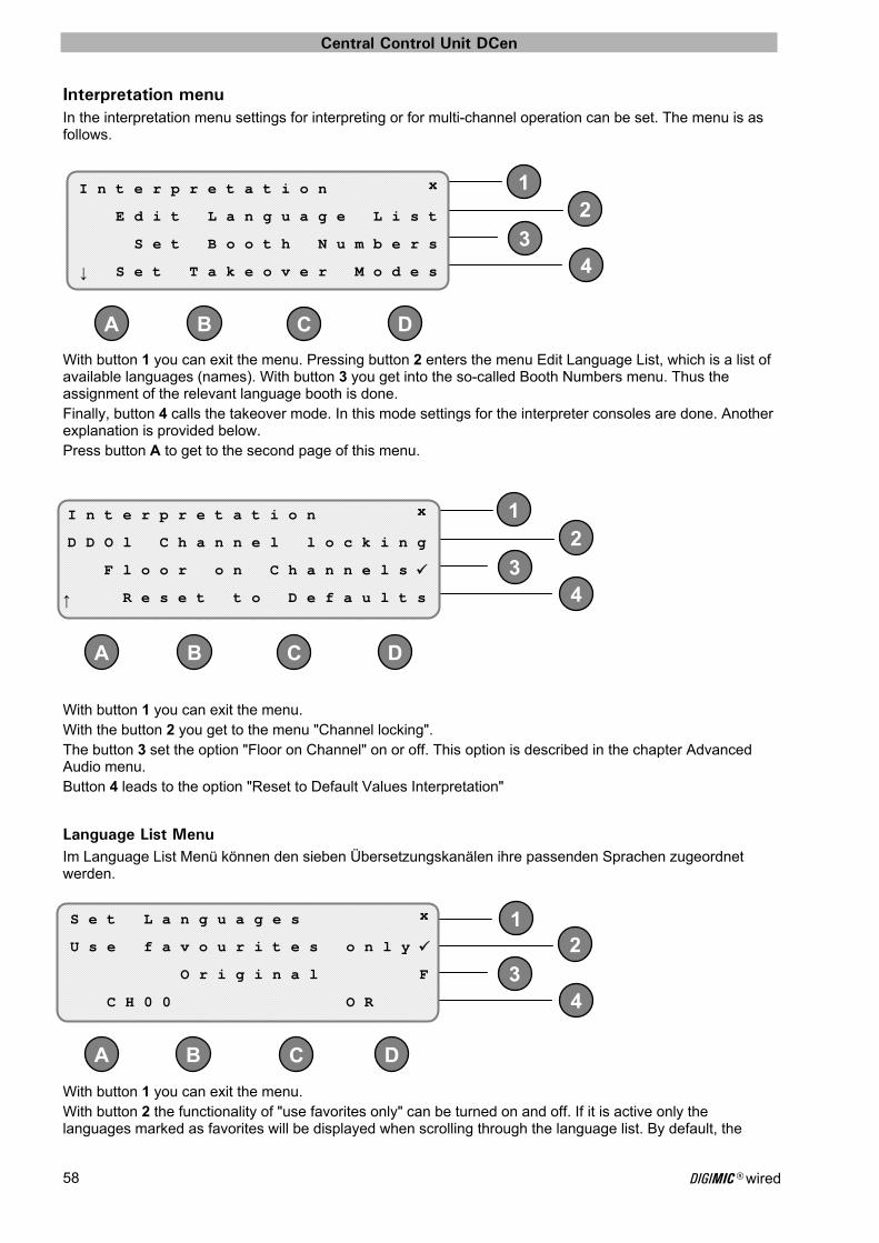
Central Control Unit DCen
DIGIMIC® wired 58
2
34
DC B A
1
12
34
DC B A
2
34
DC B A
1
Interpretation menu In the interpretation menu settings for interpreting or for multi-channel operation can be set. The menu is as follows.
With button 1 you can exit the menu. Pressing button 2 enters the menu Edit Language List, which is a list of available languages (names). With button 3 you get into the so-called Booth Numbers menu. Thus the assignment of the relevant language booth is done. Finally, button 4 calls the takeover mode. In this mode settings for the interpreter consoles are done. Another explanation is provided below. Press button A to get to the second page of this menu.
With button 1 you can exit the menu. With the button 2 you get to the menu "Channel locking". The button 3 set the option "Floor on Channel" on or off. This option is described in the chapter Advanced Audio menu. Button 4 leads to the option "Reset to Default Values Interpretation"
Language List Menu Im Language List Menü können den sieben Übersetzungskanälen ihre passenden Sprachen zugeordnet werden.
With button 1 you can exit the menu. With button 2 the functionality of "use favorites only" can be turned on and off. If it is active only the languages marked as favorites will be displayed when scrolling through the language list. By default, the
I n t e r p r e t a t i o n x
E d i t L a n g u a g e L i s t
S e t B o o t h N u m b e r s
↓ S e t T a k e o v e r M o d e s
I n t e r p r e t a t i o n x
D D O l C h a n n e l l o c k i n g
F l o o r o n C h a n n e l s
↑ R e s e t t o D e f a u l t s
S e t L a n g u a g e s x
U s e f a v o u r i t e s o n l y
O r i g i n a l F
C H 0 0 O R
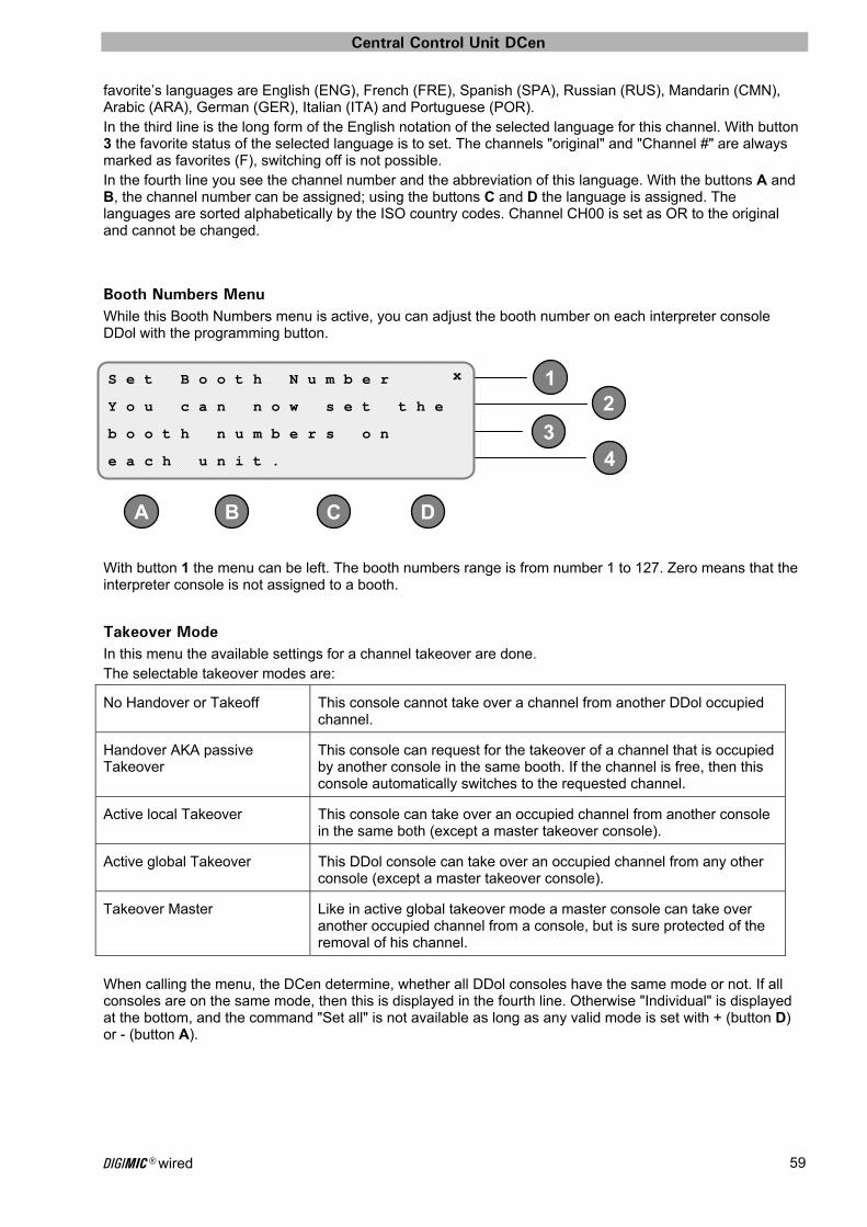
Central Control Unit DCen
DIGIMIC® wired 59
2
34
DC B A
1
favorite’s languages are English (ENG), French (FRE), Spanish (SPA), Russian (RUS), Mandarin (CMN), Arabic (ARA), German (GER), Italian (ITA) and Portuguese (POR). In the third line is the long form of the English notation of the selected language for this channel. With button 3 the favorite status of the selected language is to set. The channels "original" and "Channel #" are always marked as favorites (F), switching off is not possible. In the fourth line you see the channel number and the abbreviation of this language. With the buttons A and B, the channel number can be assigned; using the buttons C and D the language is assigned. The languages are sorted alphabetically by the ISO country codes. Channel CH00 is set as OR to the original and cannot be changed.
Booth Numbers Menu While this Booth Numbers menu is active, you can adjust the booth number on each interpreter console DDol with the programming button.
With button 1 the menu can be left. The booth numbers range is from number 1 to 127. Zero means that the interpreter console is not assigned to a booth.
Takeover Mode In this menu the available settings for a channel takeover are done. The selectable takeover modes are:
No Handover or Takeoff This console cannot take over a channel from another DDol occupied channel.
Handover AKA passive Takeover
This console can request for the takeover of a channel that is occupied by another console in the same booth. If the channel is free, then this console automatically switches to the requested channel.
Active local Takeover This console can take over an occupied channel from another console in the same both (except a master takeover console).
Active global Takeover This DDol console can take over an occupied channel from any other console (except a master takeover console).
Takeover Master Like in active global takeover mode a master console can take over another occupied channel from a console, but is sure protected of the removal of his channel.
When calling the menu, the DCen determine, whether all DDol consoles have the same mode or not. If all consoles are on the same mode, then this is displayed in the fourth line. Otherwise "Individual" is displayed at the bottom, and the command "Set all" is not available as long as any valid mode is set with + (button D) or - (button A).
S e t B o o t h N u m b e r x
Y o u c a n n o w s e t t h e
b o o t h n u m b e r s o n
e a c h u n i t .
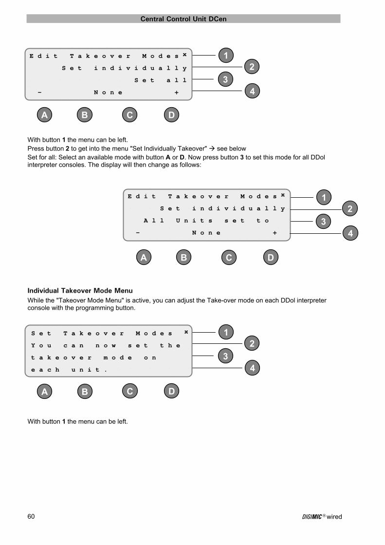
Central Control Unit DCen
DIGIMIC® wired 60
2
34
DC B A
1
12
34
D CBA
12
34
DC B A
With button 1 the menu can be left. Press button 2 to get into the menu "Set Individually Takeover" see below Set for all: Select an available mode with button A or D. Now press button 3 to set this mode for all DDol interpreter consoles. The display will then change as follows:
Individual Takeover Mode Menu While the "Takeover Mode Menu" is active, you can adjust the Take-over mode on each DDol interpreter console with the programming button.
With button 1 the menu can be left.
E d i t T a k e o v e r M o d e s x
S e t i n d i v i d u a l l y
S e t a l l
- N o n e +
E d i t T a k e o v e r M o d e s x
S e t i n d i v i d u a l l y
A l l U n i t s s e t t o
- N o n e +
S e t T a k e o v e r M o d e s x
Y o u c a n n o w s e t t h e
t a k e o v e r m o d e o n
e a c h u n i t .
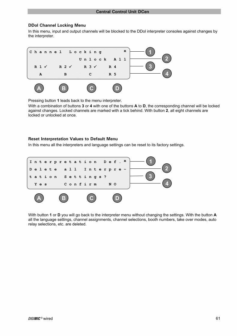
Central Control Unit DCen
DIGIMIC® wired 61
2
34
DC B A
1
12
34
DC B A
DDol Channel Locking Menu In this menu, input and output channels will be blocked to the DDol interpreter consoles against changes by the interpreter.
Pressing button 1 leads back to the menu interpreter. With a combination of buttons 3 or 4 with one of the buttons A to D, the corresponding channel will be locked against changes. Locked channels are marked with a tick behind. With button 2, all eight channels are locked or unlocked at once.
Reset Interpretation Values to Default Menu In this menu all the interpreters and language settings can be reset to its factory settings.
With button 1 or D you will go back to the interpreter menu without changing the settings. With the button A all the language settings, channel assignments, channel selections, booth numbers, take over modes, auto relay selections, etc. are deleted.
C h a n n e l L o c k i n g x
U n l o c k A l l
R 1 R 2 R 3 R 4
A B C R 5
I n t e r p r e t a t i o n D e f . x
D e l e t e a l l I n t e r p r e -
t a t i o n S e t t i n g s ?
Y e s C o n f i r m N O
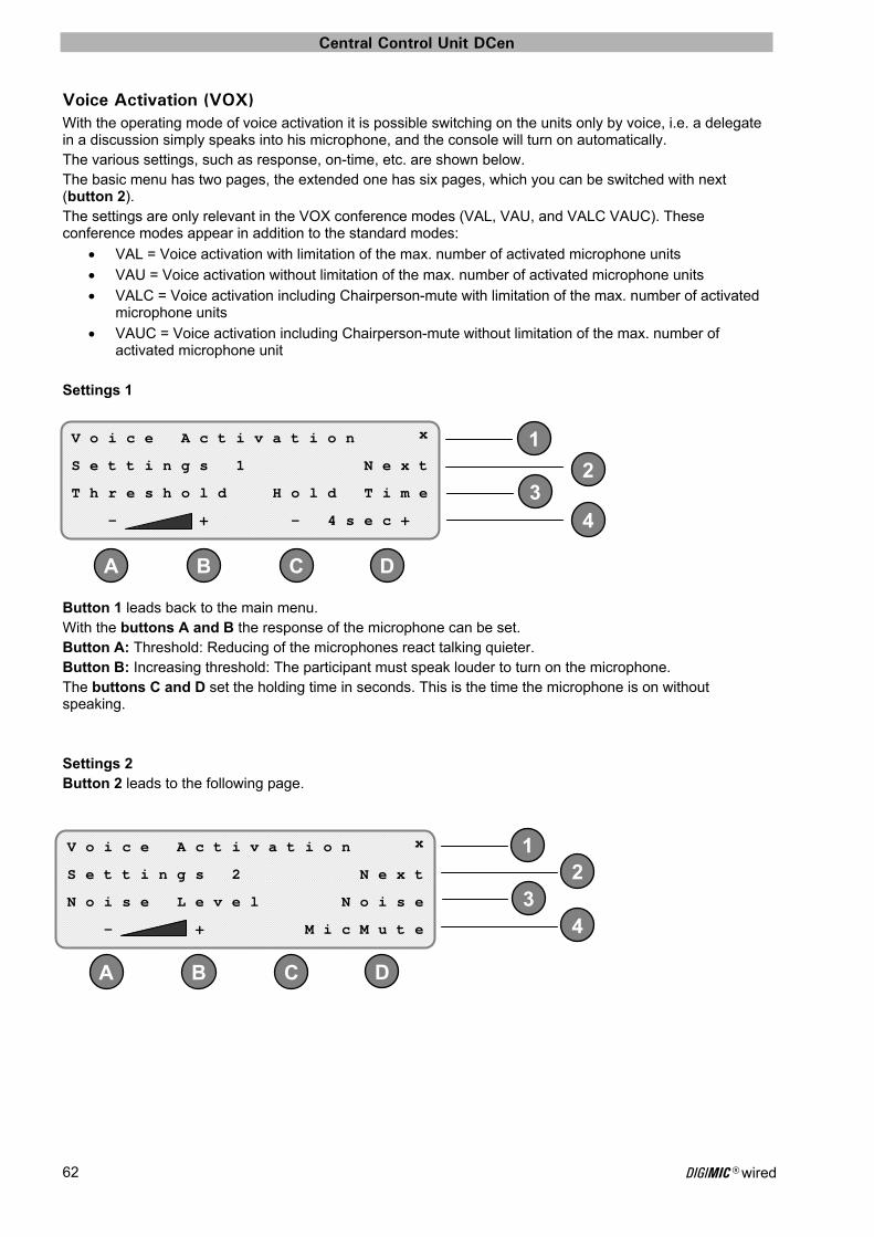
Central Control Unit DCen
DIGIMIC® wired 62
1
D
23
4
A B C
1
DC B A
23
4
Voice Activation (VOX) With the operating mode of voice activation it is possible switching on the units only by voice, i.e. a delegate in a discussion simply speaks into his microphone, and the console will turn on automatically. The various settings, such as response, on-time, etc. are shown below. The basic menu has two pages, the extended one has six pages, which you can be switched with next (button 2). The settings are only relevant in the VOX conference modes (VAL, VAU, and VALC VAUC). These conference modes appear in addition to the standard modes:
VAL = Voice activation with limitation of the max. number of activated microphone units
VAU = Voice activation without limitation of the max. number of activated microphone units
VALC = Voice activation including Chairperson-mute with limitation of the max. number of activated microphone units
VAUC = Voice activation including Chairperson-mute without limitation of the max. number of activated microphone unit
Settings 1
Button 1 leads back to the main menu. With the buttons A and B the response of the microphone can be set. Button A: Threshold: Reducing of the microphones react talking quieter. Button B: Increasing threshold: The participant must speak louder to turn on the microphone. The buttons C and D set the holding time in seconds. This is the time the microphone is on without speaking. Settings 2 Button 2 leads to the following page.
V o i c e A c t i v a t i o n x
S e t t i n g s 1 N e x t
T h r e s h o l d H o l d T i m e
- + - 4 s e c +
V o i c e A c t i v a t i o n x
S e t t i n g s 2 N e x t
N o i s e L e v e l N o i s e
- + M i c M u t e
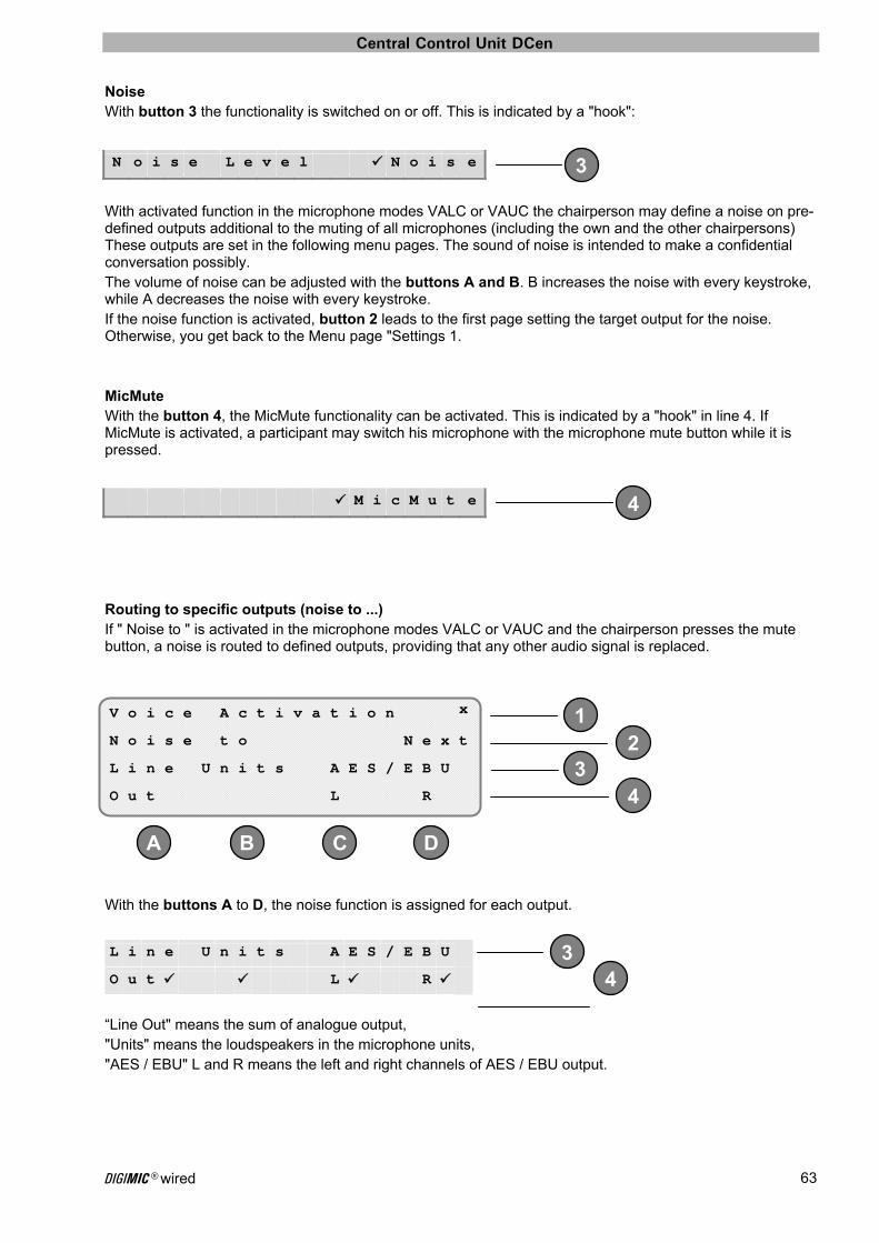
Central Control Unit DCen
DIGIMIC® wired 63
3
1
D
2 3
4
A B C
34
4
Noise With button 3 the functionality is switched on or off. This is indicated by a "hook":
With activated function in the microphone modes VALC or VAUC the chairperson may define a noise on pre-defined outputs additional to the muting of all microphones (including the own and the other chairpersons) These outputs are set in the following menu pages. The sound of noise is intended to make a confidential conversation possibly. The volume of noise can be adjusted with the buttons A and B. B increases the noise with every keystroke, while A decreases the noise with every keystroke. If the noise function is activated, button 2 leads to the first page setting the target output for the noise. Otherwise, you get back to the Menu page "Settings 1. MicMute With the button 4, the MicMute functionality can be activated. This is indicated by a "hook" in line 4. If MicMute is activated, a participant may switch his microphone with the microphone mute button while it is pressed.
Routing to specific outputs (noise to ...) If " Noise to " is activated in the microphone modes VALC or VAUC and the chairperson presses the mute button, a noise is routed to defined outputs, providing that any other audio signal is replaced.
With the buttons A to D, the noise function is assigned for each output.
“Line Out" means the sum of analogue output, "Units" means the loudspeakers in the microphone units, "AES / EBU" L and R means the left and right channels of AES / EBU output.
N o i s e L e v e l N o i s e
M i c M u t e
V o i c e A c t i v a t i o n x
N o i s e t o N e x t
L i n e U n i t s A E S / E B U
O u t L R
L i n e U n i t s A E S / E B U
O u t L R

Central Control Unit DCen
DIGIMIC® wired 64
1
D
23
4
A B C
1
D
23
4
A B C
3
3
1
D
32
4
A B C
4
4
Go to the next page (Next) with button 2
Correspondingly, button A to D set a noise to the four analogue outputs (line output). These are the outputs connecting to microphone units DMic.
Button 2 leads next to last page
In a similar way as before it is possible to send a noise signal to the first four channels of ADAT output (1 ... 4 outputs) using the buttons A to D.
Go to the last page with button 2.
V o i c e A c t i v a t i o n x
N o i s e t o N e x t
A n a l o g L i n e O u t p u t s
1 2 3 4
A n a l o g L i n e O u t p u t s
1 2 3 4
V o i c e A c t i v a t i o n x
N o i s e t o N e x t
A D A T 1 . . 4 O u t p u t s
1 2 3 4
A D A T 1 . . 4 O u t p u t s
1 2 3 4
V o i c e A c t i v a t i o n x
N o i s e t o N e x t
A D A T 5 . . 8 O u t p u t s
5 6 7 8

Central Control Unit DCen
DIGIMIC® wired 65
34
In a similar way as before it is possible to send a noise signal to the second four channels of ADAT output (5 ... 8 outputs) using the buttons A to D.
Press the button 2 to return to the menu page "Settings 1”.
A D A T 5 . . 8 O u t p u t s
5 6 7 8

Central Control Unit DCen
DIGIMIC® wired 66
1
23
4
DC B A
4
DC B A
3
4
DC B A
DSpark Settings Please refer also to the DIGIMIC wireless manual.
When calling the DSpark settings you will see the following menu:
Button 1 leads back within the menu. In Line 2 is displayed on which communication line (e.g. Line 1) and at which position in that chain (e.g. Unit 1) a DSpark is connected. If multiple DSparks are connected to the DCen with button 2 you may switch to the next DSpark. In Line 3 is displayed the current selected parameter of the DSpark. Press button 3 to toggle through the parameters. The corresponding values or actions are displayed in Line 4. DSpark setting menus: Register Control (see following pages) Standby Timeout
Multi-Room Control Protocol Selection
RF Power RF Spectrum Setting Configuration File Register File System Info Factory Defaults
Register Control In that section you can show / edit the register list status of the recognized DDoc units by the DSpark.
If the register list of recognized DDoc units is empty this is displayed with “None Online”. That means there are no units registered by the DSpark. If at least one unit is registered, the display switches to “Erase”. With button A you can now delete the list. With button D you can change the state of the register list between “Opened” (new DDoc units can be added to the list) and “Closed” (further [unregistered] DDoc units are not accepted). These features are important for multi-room functionality to particular assign DDoc units and close the existing list.
Opened: new DDoc units can be added to the register list (Setup scenario) Closed: further DDoc units are not longer accepted (Conference scenario)
D S p a r k S e t t i n g s x
L i n e 1 U n i t 1 O n l i n e
R e g i s t e r C o n t r o l
E r a s e O p e n e d
R e g i s t e r C o n t r o l
E r a s e n o n e O p e n e d
E r a s e 1 5 C l o s e d
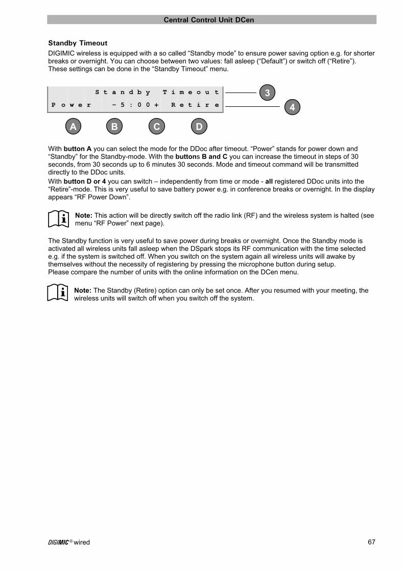
Central Control Unit DCen
DIGIMIC® wired 67
4
DC B A
3
Standby Timeout DIGIMIC wireless is equipped with a so called “Standby mode” to ensure power saving option e.g. for shorter breaks or overnight. You can choose between two values: fall asleep (“Default”) or switch off (“Retire”). These settings can be done in the “Standby Timeout” menu.
With button A you can select the mode for the DDoc after timeout. “Power” stands for power down and “Standby” for the Standby-mode. With the buttons B and C you can increase the timeout in steps of 30 seconds, from 30 seconds up to 6 minutes 30 seconds. Mode and timeout command will be transmitted directly to the DDoc units. With button D or 4 you can switch – independently from time or mode - all registered DDoc units into the “Retire”-mode. This is very useful to save battery power e.g. in conference breaks or overnight. In the display appears “RF Power Down”.
Note: This action will be directly switch off the radio link (RF) and the wireless system is halted (see menu “RF Power” next page).
The Standby function is very useful to save power during breaks or overnight. Once the Standby mode is activated all wireless units fall asleep when the DSpark stops its RF communication with the time selected e.g. if the system is switched off. When you switch on the system again all wireless units will awake by themselves without the necessity of registering by pressing the microphone button during setup. Please compare the number of units with the online information on the DCen menu.
Note: The Standby (Retire) option can only be set once. After you resumed with your meeting, the wireless units will switch off when you switch off the system.
S t a n d b y T i m e o u t
P o w e r - 5 : 0 0 + R e t i r e

Central Control Unit DCen
DIGIMIC® wired 68
4
DC B A
3
4
DC B A
3
4
4
4
4
4
Multi-Room Control To operate multiple DSparks in parallel (Multi-Room operation) each DSpark must be assigned with its own "room no.". There are five different rooms available from 0 to 4. Default value is 0. The room number can be toggled with buttons D or 4.
The room assignment for the accessible DDoc units can be removed by simultaneously pressing buttons A and B. This could be done e.g. at the end of a rental conference. At next power up at a new conference location, these units are looking for a DSpark with any room assignment.
Protocol Selection The protocol selection within the DSpark may be changed with DCen only. There are five different radio protocols (performance levels) available. The currently selected performance level is shown in the fourth display line. These can be altered by pressing buttons 4 or D cyclically. The default value is 1 + standard latency.
DIGIMIC wireless with protocol option #1 is suitable for the most conference areas. Just in case you discover dropouts on the audio or weak RF connections, because of a very strong radio emitter nearby, you can adapt the system accordingly.
#1
#2
#3
#4
#5
M u l t i R o o m C o n t r o l
R e s e t D D o c R o o m 0
P r o t o c o l S e l e c t i o n
1 + s t a n d a r d l a t e n c y
1 + s t a n d a r d l a t e n c y
1 + l o w l a t e n c y
1 + u l t r a l o w l a t e n c y
2 + s t a n d a r d l a t e n c y
2 + l o w l a t e n c y
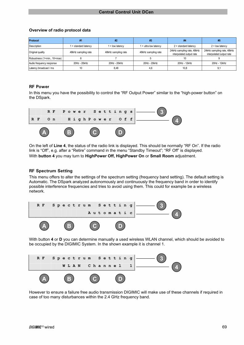
Central Control Unit DCen
DIGIMIC® wired 69
Protocol #1 #2 #3 #4 #5
Description 1 + standard latency 1 + low latency 1 + ultra low latency 2 + standard latency 2 + low latency
Original quality 48kHz sampling rate 48kHz sampling rate 48kHz sampling rate24kHz sampling rate, 48kHz
interpolated output rate24kHz sampling rate, 48kHz
interpolated output rate
Robustness (1=min., 10=max) 8 7 5 10 9
Audio frequency response 20Hz - 20kHz 20Hz - 20kHz 20Hz - 20kHz 20Hz - 12kHz 20Hz - 12kHz
Latency broadcast / ms 10 8,48 4,6 10,8 9,1
4
DC B A
3
4
DC B A
3
4
DC B A
3
Overview of radio protocol data
RF Power In this menu you have the possibility to control the “RF Output Power” similar to the “high-power button” on the DSpark.
On the left of Line 4, the status of the radio link is displayed. This should be normally “RF On”. If the radio link is “Off”, e.g. after a “Retire” command in the menu “Standby Timeout”; “RF Off” is displayed. With button 4 you may turn to HighPower Off, HighPower On or Small Room adjustment.
RF Spectrum Setting This menu offers to alter the settings of the spectrum setting (frequency band setting). The default setting is Automatic. The DSpark analyzed autonomously and continuously the frequency band in order to identify possible interference frequencies and tries to avoid using them. This could for example be a wireless network.
With button 4 or D you can determine manually a used wireless WLAN channel, which should be avoided to be occupied by the DIGIMIC System. In the shown example it is channel 1.
However to ensure a failure free audio transmission DIGIMIC will make use of these channels if required in case of too many disturbances within the 2.4 GHz frequency band.
R F P o w e r S e t t i n g s
R F O n H i g h P o w e r O f f
R F S p e c t r u m S e t t i n g
A u t o m a t i c
R F S p e c t r u m S e t t i n g
W L A N C h a n n e l 1
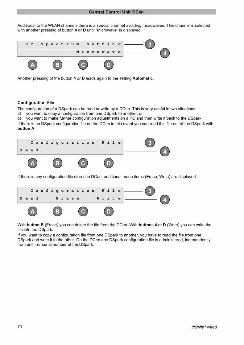
Central Control Unit DCen
DIGIMIC® wired 70
4
DC B A
3
4
DC B A
3
4
DC B A
3
Additional to the WLAN channels there is a special channel avoiding microwaves. This channel is selected with another pressing of button 4 or D until “Microwave” is displayed.
Another pressing of the button 4 or D leads again to the setting Automatic.
Configuration File The configuration of a DSpark can be read or write by a DCen. This is very useful in two situations: a) you want to copy a configuration from one DSpark to another, or b) you want to make further configuration adjustments on a PC and then write it back to the DSpark. If there is no DSpark configuration file on the DCen in this event you can read this file out of the DSpark with button A.
If there is any configuration file stored in DCen, additional menu items (Erase, Write) are displayed:
With button B (Erase) you can delete the file from the DCen. With buttons 4 or D (Write) you can write the file into the DSpark. If you want to copy a configuration file from one DSpark to another, you have to read the file from one DSpark and write it to the other. On the DCen one DSpark configuration file is administered, independently from unit - or serial number of the DSpark.
R F S p e c t r u m S e t t i n g
M i c r o w a v e
C o n f i g u r a t i o n F i l e
R e a d
C o n f i g u r a t i o n F i l e
R e a d E r a s e W r i t e
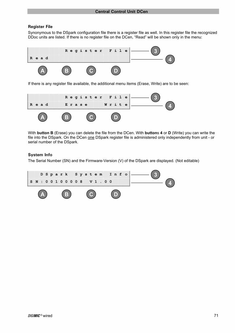
Central Control Unit DCen
DIGIMIC® wired 71
4
DC B A
3
4
DC B A
3
4
DC B A
3
Register File Synonymous to the DSpark configuration file there is a register file as well. In this register file the recognized DDoc units are listed. If there is no register file on the DCen, “Read” will be shown only in the menu:
If there is any register file available, the additional menu items (Erase, Write) are to be seen:
With button B (Erase) you can delete the file from the DCen. With buttons 4 or D (Write) you can write the file into the DSpark. On the DCen one DSpark register file is administered only independently from unit - or serial number of the DSpark.
System Info The Serial Number (SN) and the Firmware-Version (V) of the DSpark are displayed. (Not editable)
R e g i s t e r F i l e
R e a d
R e g i s t e r F i l e
R e a d E r a s e W r i t e
D S p a r k S y s t e m I n f o
S N : 0 0 1 0 0 0 0 8 V 1 . 0 0
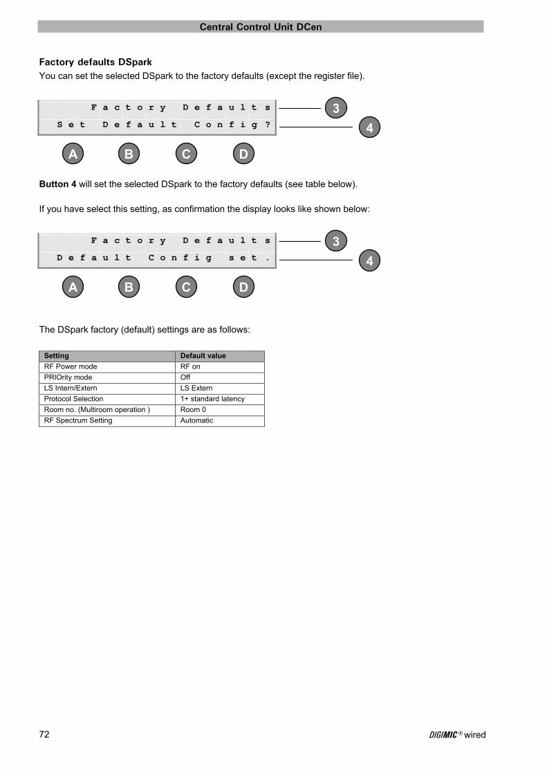
Central Control Unit DCen
DIGIMIC® wired 72
4
DC B A
3
4
DC B A
3
Factory defaults DSpark You can set the selected DSpark to the factory defaults (except the register file).
Button 4 will set the selected DSpark to the factory defaults (see table below). If you have select this setting, as confirmation the display looks like shown below:
The DSpark factory (default) settings are as follows:
Setting Default value
RF Power mode RF on
PRIOrity mode Off
LS Intern/Extern LS Extern
Protocol Selection 1+ standard latency
Room no. (Multiroom operation ) Room 0
RF Spectrum Setting Automatic
F a c t o r y D e f a u l t s
S e t D e f a u l t C o n f i g ?
F a c t o r y D e f a u l t s
D e f a u l t C o n f i g s e t .

Central Control Unit DCen
DIGIMIC® wired 73
1
D
32
4
A B C
1
D
32
4
A B C
Audio Boost The setting audio boost can increased the audio level of the microphone speaker of DCen by 12dB.
This is only related for DMic units of the first generation. Current DMic and CMic units have a higher microphone level. The use of the audio boost with newer units can lead quickly to feedback.
Press button 1 to return to configuration page. Button 2 will activate or deactivate the Audio Boost feature. Enabling Audio boost results in the following menu:
With enabled audio boost there is an asterisk in the main menu to the right of the volume (page 37).
A u d i o B o o s t F e a t u r e x
A u d i o B o o s t d i s a b l e d
A u d i o B o o s t F e a t u r e x
A u d i o B o o s t e n a b l e d
W a r n i n g ! C o n s u l t
M a n u a l f o r D e t a i l s !

Central Control Unit DCen
DIGIMIC® wired 74
2
34
DC B A
1
23
4
DC B A
1
23
4
DC B A
1
DCen Factory defaults
Note: If you recall the factory settings all personal settings will be lost!
This menu may include any or all parts of the setting DCEN be reset to its factory defaults.
Button 1 leads back in menu (sign X) Button 3 leads to a submenu for interpreter defaults, which are described in the section "interpreters" (see page 61). With button 4 you get to the memory settings of DCEN. With button 2, all settings can be reset.
Leave the menu with button 1 or D without saving changes. With the button A, all settings are cleared and the system is restarted.
Setting Storage Menu Since version 3.0 the DCEN has its own storage area for the adjustable parameters like volume, seat numbers, network settings, etc. This area is managed as a file system. In the Settings menu storage you can see how much space is consumed and how fragmented the file system is. Furthermore you can delete and reorganize the file system.
With the button 1 the menu will be left. In the second line you see the load factor on the file system.
F a c t o r y D e f a u l t s x
A l l F a c t o r y D e f a u l t s
I n t E r p r e t . D e f a u l t s
C o n f I g S t o r a g e C t r l .
F a c t o r y d e f a u l t s x
D e l e t e a l l S e t t i n g s
a n d r e b o o t t h e D C e n
Y e s C o n f i r m N o
S e t t i n g s S t o r a g e x
0 . 4 % F u l l
1 . 4 % F r a g m e n t a t i o n
E r a s e A l l C l e a n U p
Central Control Unit DCen
DIGIMIC® wired 75
The third line shows how much of this space already has been marked as deleted and would be recovered in reorganization. The percentage refers to the used items, so that for example, represents 98.0% fragmentation at 0.3% full not a problem. With the button combination A + B, the file system will be completely erased (formatted). This deletes any custom settings. This change becomes effective only after the system restarts. Attitudinal changes after formatting but before the reboot, however, are saved. If the file system is deleted, then the Erase All and Clean Up options are not displayed. With the button combination C + D the file system to be reorganized (defragmented). If the file system is organized perfectly, then the Clean Up option is not displayed.
Push to talk If this setting is enabled the microphone in non-VOX mode (voice control) switches on by pressing the microphone button and switches off by releasing it. The switching on reaction of the microphone depends on the mode and the current parameters, that means, it is subject to the current limitation with respect to the open microphone for delegates and VIPs. For example, with current settings AUTN with DEL2 and two microphones are already open, then a third delegate get only a request when pressing the microphone button, but not an open microphone. If any of the other delegates releases his microphone button, while a third one still holds his microphone button, his microphone is switched on.

Conference Units
DIGIMIC® wired 76
Chairpersons Conference Unit DChair The Chairpersons' unit DChair is the conference leaders' frontend for communication within the DIGIMIC discussion system matching the necessary requirements. To emphasize the Chairpersons' importance this unit can be activated at any time independent of any system status. It also is equipped with an extra "mute all" button to override any active delegate if required. The two integrated loudspeakers provide even decentralized voice amplification to increase the speech intelligibility especially for conference areas without a PA system. In addition each DChair is equipped with an amplified headphone socket and corresponding volume control. The wired product may be easily upgraded by adding the docking unit DDoc with radio transmission technology and a rechargeable battery, which supports wireless applications. This upgrade transforms a formerly wired delegate unit into a wireless unit. This represents a new and exciting technology that will have real world use in a wide variety of applications.
User controls and connections Up to 25 units can be connected to one line. If the cover at the connectors is not withdrawn, remove the cover like shown on page 13. 1. Connector socket NEXT (S8G),
for connection of the next unit 2. Connector socket PREVIOUS (S8G),
for connection of the previous unit 3. Connector socket (Minicon), for microphone connection (TM58/6) 4. Built-in loudspeaker,
integrated loudspeaker for decentralized audio amplification
5. “mute all” button,
illuminated “mute all” button for permanent or temporarily overriding of all active delegate microphone units
6. Microphone push button switch,
illuminated microphone button for indication MIC ON/OFF, REQUEST
7. Volume control push-buttons,
volume control for headphone 8. Mini jack connector (3.5 mm),
for headphone connection
1 2
8
7
3
4
6
5
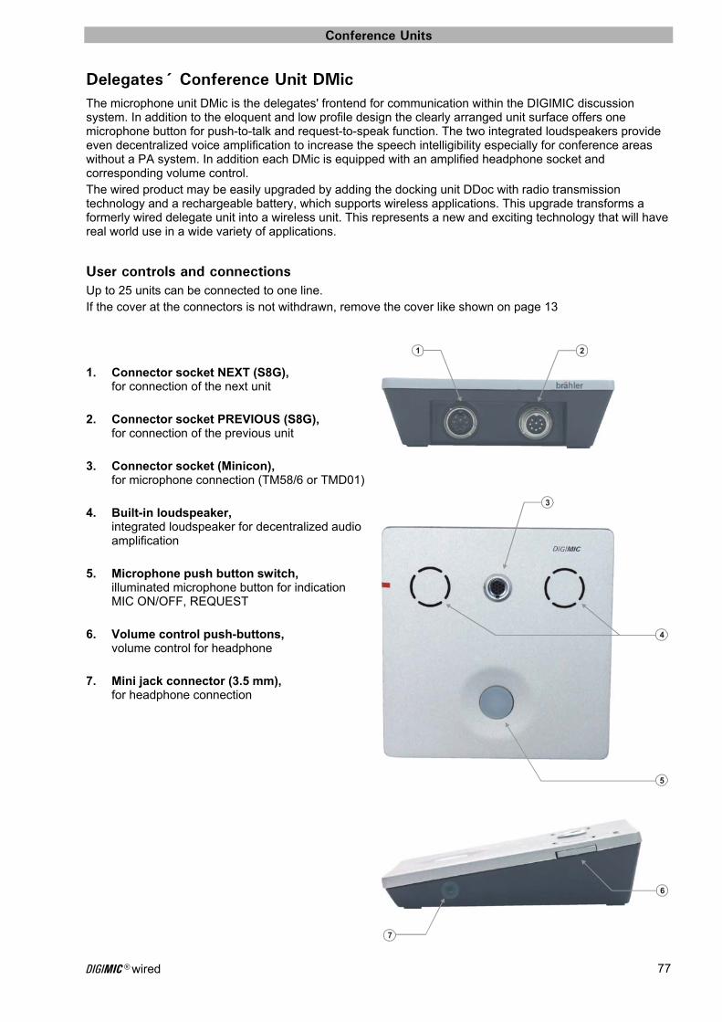
Conference Units
DIGIMIC® wired 77
Delegates´ Conference Unit DMic The microphone unit DMic is the delegates' frontend for communication within the DIGIMIC discussion system. In addition to the eloquent and low profile design the clearly arranged unit surface offers one microphone button for push-to-talk and request-to-speak function. The two integrated loudspeakers provide even decentralized voice amplification to increase the speech intelligibility especially for conference areas without a PA system. In addition each DMic is equipped with an amplified headphone socket and corresponding volume control. The wired product may be easily upgraded by adding the docking unit DDoc with radio transmission technology and a rechargeable battery, which supports wireless applications. This upgrade transforms a formerly wired delegate unit into a wireless unit. This represents a new and exciting technology that will have real world use in a wide variety of applications.
User controls and connections Up to 25 units can be connected to one line. If the cover at the connectors is not withdrawn, remove the cover like shown on page 13 1. Connector socket NEXT (S8G),
for connection of the next unit 2. Connector socket PREVIOUS (S8G),
for connection of the previous unit 3. Connector socket (Minicon),
for microphone connection (TM58/6 or TMD01) 4. Built-in loudspeaker,
integrated loudspeaker for decentralized audio amplification
5. Microphone push button switch,
illuminated microphone button for indication MIC ON/OFF, REQUEST
6. Volume control push-buttons,
volume control for headphone 7. Mini jack connector (3.5 mm),
for headphone connection
1 2
7
6
3
4
5
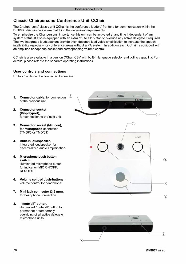
Conference Units
DIGIMIC® wired 78
Classic Chairpersons Conference Unit CChair The Chairpersons' classic unit CChair is the conference leaders' frontend for communication within the DIGIMIC discussion system matching the necessary requirements. To emphasize the Chairpersons' importance this unit can be activated at any time independent of any system status. It also is equipped with an extra "mute all" button to override any active delegate if required. The two integrated loudspeakers provide even decentralized voice amplification to increase the speech intelligibility especially for conference areas without a PA system. In addition each CChair is equipped with an amplified headphone socket and corresponding volume control. CChair is also available in a version CChair CSV with built-in language selector and voting capability. For details, please refer to the separate operating instructions.
User controls and connections Up to 25 units can be connected to one line. 1. Connector cable, for connection
of the previous unit 2. Connector socket
(Displayport), for connection to the next unit
3. Connector socket (Minicon),
for microphone connection (TM58/6 or TMD/01)
4. Built-in loudspeaker,
integrated loudspeaker for decentralized audio amplification
5. Microphone push button
switch, illuminated microphone button for indication MIC ON/OFF, REQUEST
6. Volume control push-buttons,
volume control for headphone 7. Mini jack connector (3.5 mm),
for headphone connection 8. “mute all” button,
illuminated “mute all” button for permanent or temporarily overriding of all active delegate microphone units
1
2
7
6
3
4
5
8
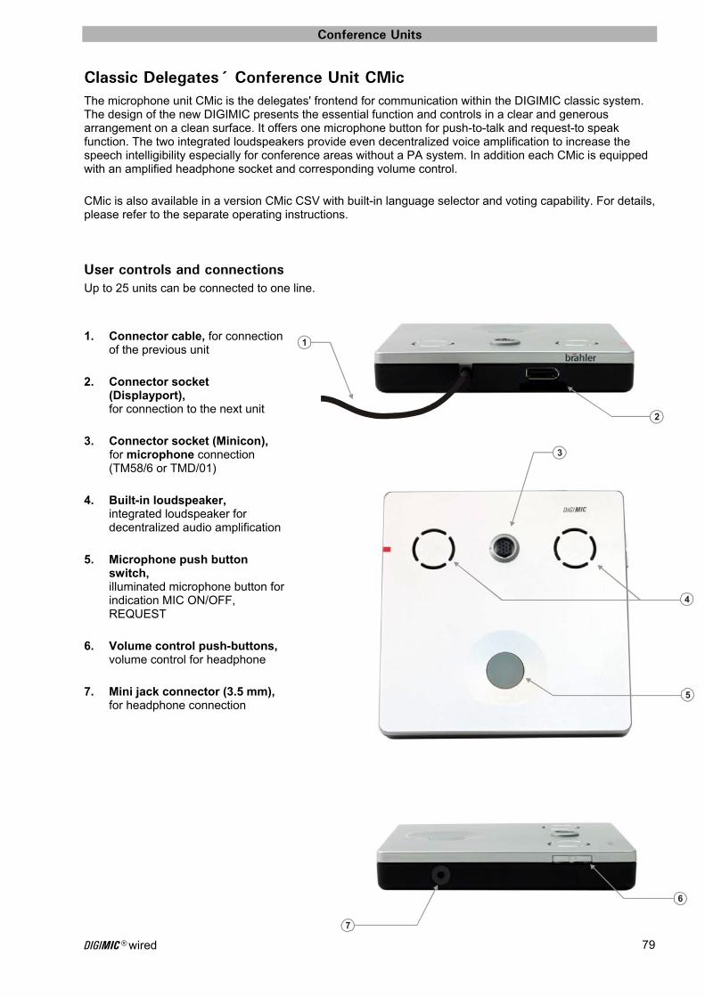
Conference Units
DIGIMIC® wired 79
Classic Delegates´ Conference Unit CMic The microphone unit CMic is the delegates' frontend for communication within the DIGIMIC classic system. The design of the new DIGIMIC presents the essential function and controls in a clear and generous arrangement on a clean surface. It offers one microphone button for push-to-talk and request-to speak function. The two integrated loudspeakers provide even decentralized voice amplification to increase the speech intelligibility especially for conference areas without a PA system. In addition each CMic is equipped with an amplified headphone socket and corresponding volume control. CMic is also available in a version CMic CSV with built-in language selector and voting capability. For details, please refer to the separate operating instructions.
User controls and connections Up to 25 units can be connected to one line. 1. Connector cable, for connection
of the previous unit 2. Connector socket
(Displayport), for connection to the next unit
3. Connector socket (Minicon),
for microphone connection (TM58/6 or TMD/01)
4. Built-in loudspeaker,
integrated loudspeaker for decentralized audio amplification
5. Microphone push button
switch, illuminated microphone button for indication MIC ON/OFF, REQUEST
6. Volume control push-buttons,
volume control for headphone 7. Mini jack connector (3.5 mm),
for headphone connection
1
2
7
6
3
4
5

Conference Units
DIGIMIC® wired 80
DExt – extension power supply unit The DExt repeater unit is designed for expanding the DIGIMIC system. This allows operating beyond 100 delegate units (25 per chain) with one digital central unit DCen. With the DExt additional 25 microphone units can be used in a chain. Besides generating sufficient power it also refreshes the digital audio signals. The DExt can also be used as a line driver to expand the D9 cable connection. This is for instance useful if the connection from the central unit DCen to the first device exceeds the system-defined dimension of 100m. With DExt additional 100m in the chain can be bridged. See example on page 87
Connections PREVIOUS (D9 connector) Connection of previous units with D9 cable NEXT (D9 socket) Connection of next units with D9 cable Plug socket for power connection Features Green LED for output power indication (48 V) Power Supply Mains Power In: (90 ... 240) VAC, (50 ...60) Hz Power Consumption: 120 W max. Housing Aluminium, "silver" anodized W x H x L: (100 x 43 x 233) mm Weight approx. 1.0 kg
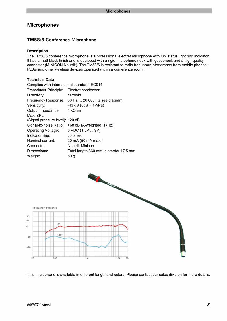
Microphones
DIGIMIC® wired 81
Microphones
TM58/6 Conference Microphone Description The TM58/6 conference microphone is a professional electret microphone with ON status light ring indicator. It has a matt black finish and is equipped with a rigid microphone neck with gooseneck and a high quality connector (MINICON Neutrik). The TM58/6 is resistant to radio frequency interference from mobile phones, PDAs and other wireless devices operated within a conference room. Technical Data Complies with international standard IEC914 Transducer Principle: Electret condenser Directivity: cardioid Frequency Response: 30 Hz ... 20.000 Hz see diagram Sensitivity: -43 dB (0dB = 1V/Pa) Output Impedance: 1 kOhm Max. SPL (Signal pressure level): 120 dB Signal-to-noise Ratio: >68 dB (A-weighted, 1kHz) Operating Voltage: 5 VDC (1.5V ... 9V) Indicator ring: color red Nominal current: 20 mA (50 mA max.) Connector: Neutrik Minicon Dimensions: Total length 360 mm, diameter 17.5 mm Weight: 80 g
This microphone is available in different length and colors. Please contact our sales division for more details.
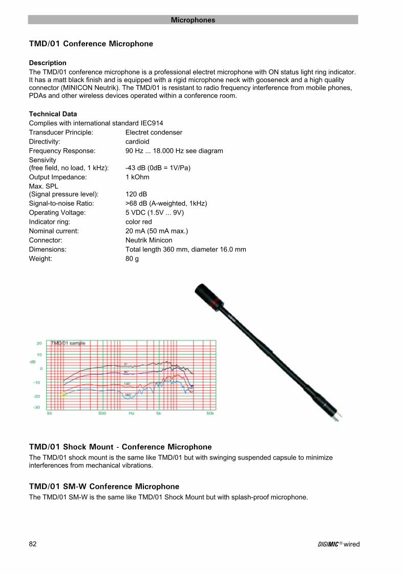
Microphones
DIGIMIC® wired 82
TMD/01 Conference Microphone
Description The TMD/01 conference microphone is a professional electret microphone with ON status light ring indicator. It has a matt black finish and is equipped with a rigid microphone neck with gooseneck and a high quality connector (MINICON Neutrik). The TMD/01 is resistant to radio frequency interference from mobile phones, PDAs and other wireless devices operated within a conference room. Technical Data Complies with international standard IEC914 Transducer Principle: Electret condenser Directivity: cardioid Frequency Response: 90 Hz ... 18.000 Hz see diagram Sensivity (free field, no load, 1 kHz): -43 dB (0dB = 1V/Pa) Output Impedance: 1 kOhm Max. SPL (Signal pressure level): 120 dB Signal-to-noise Ratio: >68 dB (A-weighted, 1kHz) Operating Voltage: 5 VDC (1.5V ... 9V) Indicator ring: color red Nominal current: 20 mA (50 mA max.) Connector: Neutrik Minicon Dimensions: Total length 360 mm, diameter 16.0 mm Weight: 80 g
TMD/01 Shock Mount - Conference Microphone The TMD/01 shock mount is the same like TMD/01 but with swinging suspended capsule to minimize interferences from mechanical vibrations.
TMD/01 SM-W Conference Microphone The TMD/01 SM-W is the same like TMD/01 Shock Mount but with splash-proof microphone.
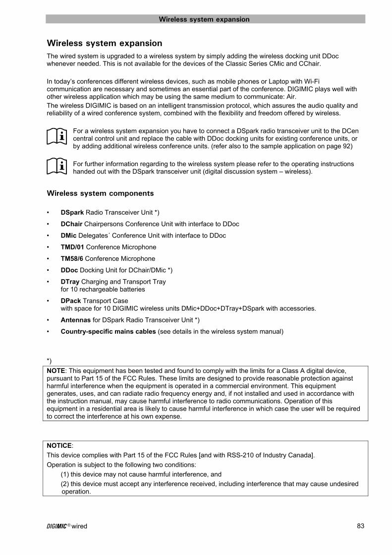
Wireless system expansion
DIGIMIC® wired 83
Wireless system expansion The wired system is upgraded to a wireless system by simply adding the wireless docking unit DDoc whenever needed. This is not available for the devices of the Classic Series CMic and CChair. In today’s conferences different wireless devices, such as mobile phones or Laptop with Wi-Fi communication are necessary and sometimes an essential part of the conference. DIGIMIC plays well with other wireless application which may be using the same medium to communicate: Air. The wireless DIGIMIC is based on an intelligent transmission protocol, which assures the audio quality and reliability of a wired conference system, combined with the flexibility and freedom offered by wireless.
For a wireless system expansion you have to connect a DSpark radio transceiver unit to the DCen central control unit and replace the cable with DDoc docking units for existing conference units, or by adding additional wireless conference units. (refer also to the sample application on page 92) For further information regarding to the wireless system please refer to the operating instructions handed out with the DSpark transceiver unit (digital discussion system – wireless).
Wireless system components • DSpark Radio Transceiver Unit *)
• DChair Chairpersons Conference Unit with interface to DDoc
• DMic Delegates´ Conference Unit with interface to DDoc
• TMD/01 Conference Microphone
• TM58/6 Conference Microphone
• DDoc Docking Unit for DChair/DMic *)
• DTray Charging and Transport Tray for 10 rechargeable batteries
• DPack Transport Case with space for 10 DIGIMIC wireless units DMic+DDoc+DTray+DSpark with accessories.
• Antennas for DSpark Radio Transceiver Unit *)
• Country-specific mains cables (see details in the wireless system manual)
*)
NOTE: This equipment has been tested and found to comply with the limits for a Class A digital device, pursuant to Part 15 of the FCC Rules. These limits are designed to provide reasonable protection against harmful interference when the equipment is operated in a commercial environment. This equipment generates, uses, and can radiate radio frequency energy and, if not installed and used in accordance with the instruction manual, may cause harmful interference to radio communications. Operation of this equipment in a residential area is likely to cause harmful interference in which case the user will be required to correct the interference at his own expense.
NOTICE:
This device complies with Part 15 of the FCC Rules [and with RSS-210 of Industry Canada].
Operation is subject to the following two conditions:
(1) this device may not cause harmful interference, and
(2) this device must accept any interference received, including interference that may cause undesired operation.
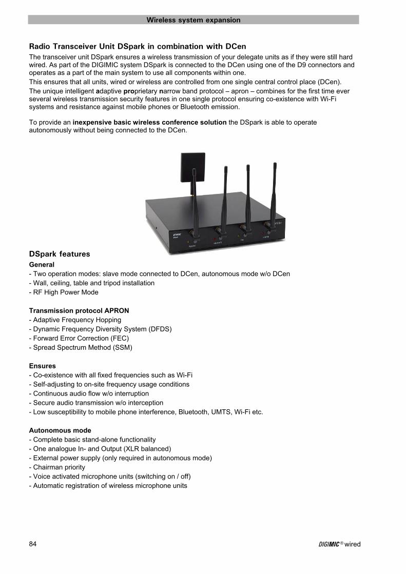
Wireless system expansion
DIGIMIC® wired 84
Radio Transceiver Unit DSpark in combination with DCen The transceiver unit DSpark ensures a wireless transmission of your delegate units as if they were still hard wired. As part of the DIGIMIC system DSpark is connected to the DCen using one of the D9 connectors and operates as a part of the main system to use all components within one. This ensures that all units, wired or wireless are controlled from one single central control place (DCen). The unique intelligent adaptive proprietary narrow band protocol – apron – combines for the first time ever several wireless transmission security features in one single protocol ensuring co-existence with Wi-Fi systems and resistance against mobile phones or Bluetooth emission.
To provide an inexpensive basic wireless conference solution the DSpark is able to operate autonomously without being connected to the DCen.
DSpark features General - Two operation modes: slave mode connected to DCen, autonomous mode w/o DCen - Wall, ceiling, table and tripod installation - RF High Power Mode Transmission protocol APRON - Adaptive Frequency Hopping - Dynamic Frequency Diversity System (DFDS) - Forward Error Correction (FEC) - Spread Spectrum Method (SSM) Ensures - Co-existence with all fixed frequencies such as Wi-Fi - Self-adjusting to on-site frequency usage conditions - Continuous audio flow w/o interruption - Secure audio transmission w/o interception - Low susceptibility to mobile phone interference, Bluetooth, UMTS, Wi-Fi etc. Autonomous mode - Complete basic stand-alone functionality - One analogue In- and Output (XLR balanced) - External power supply (only required in autonomous mode) - Chairman priority - Voice activated microphone units (switching on / off) - Automatic registration of wireless microphone units
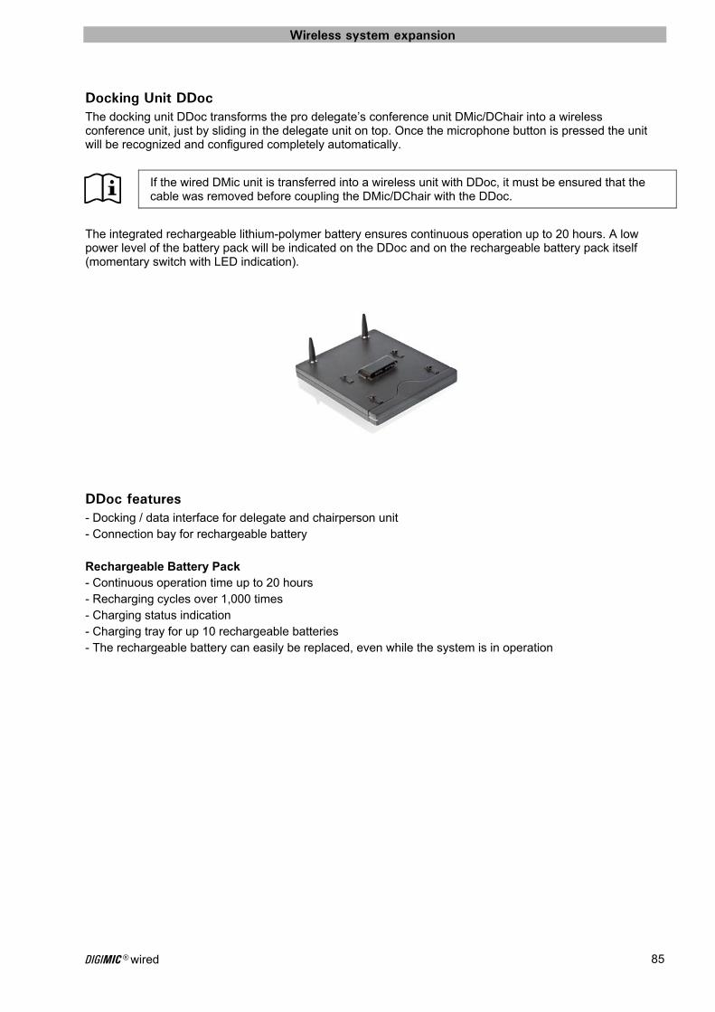
Wireless system expansion
DIGIMIC® wired 85
Docking Unit DDoc The docking unit DDoc transforms the pro delegate’s conference unit DMic/DChair into a wireless conference unit, just by sliding in the delegate unit on top. Once the microphone button is pressed the unit will be recognized and configured completely automatically.
If the wired DMic unit is transferred into a wireless unit with DDoc, it must be ensured that the cable was removed before coupling the DMic/DChair with the DDoc.
The integrated rechargeable lithium-polymer battery ensures continuous operation up to 20 hours. A low power level of the battery pack will be indicated on the DDoc and on the rechargeable battery pack itself (momentary switch with LED indication).
DDoc features - Docking / data interface for delegate and chairperson unit - Connection bay for rechargeable battery Rechargeable Battery Pack - Continuous operation time up to 20 hours - Recharging cycles over 1,000 times - Charging status indication - Charging tray for up 10 rechargeable batteries - The rechargeable battery can easily be replaced, even while the system is in operation

Wireless system expansion
DIGIMIC® wired 86

Appendix
DIGIMIC® wired 87
Appendix Sample applications
DIGIMIC Discussion system – wired, with extension power supply
Multiroom solution - wired - Example 1
MicrophoneTMD/01orTM58/6
Up to 100 wired units on 4 lines (standard)
D9 cable D9 cable
D9 cable
D9 cable
DSparkRadio Transceiver Unit
D9 cable
DCenCentral Control Unit
D9
cab
le
D9 cable
InputExternal Audio and Data
OutputPA SystemNetworkMedia ControlSI SystemSoftware
Delegates’ unit DMic
Delegates’ unit DMic
Chairpersons’ unit DChair
MicrophoneTMD/01orTM58/6
DExtup to 25
Line extended with DExt
DExt
DExt
up to 50m
up to 100m
up to 25
up to 100m
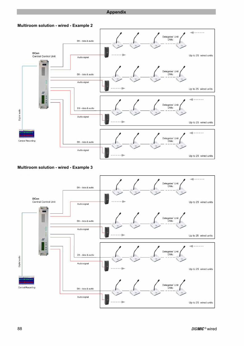
Appendix
DIGIMIC® wired 88
Multiroom solution - wired - Example 2
Multiroom solution - wired - Example 3
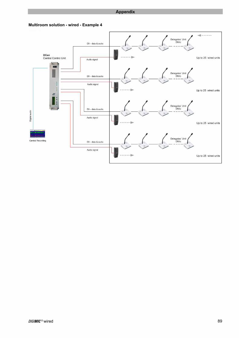
Appendix
DIGIMIC® wired 89
Multiroom solution - wired - Example 4

Appendix
DIGIMIC® wired 90
DIGIMIC Discussion system - wireless
Multiroom solution - wireless - Example 1

Appendix
DIGIMIC® wired 91
Multiroom solution - wireless - Example 2

Appendix
DIGIMIC® wired 92
DIGIMIC Discussion system - wired and wireless
Wireless Delegate Units DMic/DChair with DDoc
TMD/01orTM58/6
Wired Delegate Units DMic/DChair
D9 cable D9 cable
D9 cable
D9 cable
DSparkRadio Transceiver Unit
DCenCentral Control Unit
D9 cable
TMD/01orTM58/6
Connections see product information
Connections see product information
Multiroom solution – wired and wireless - Example 1
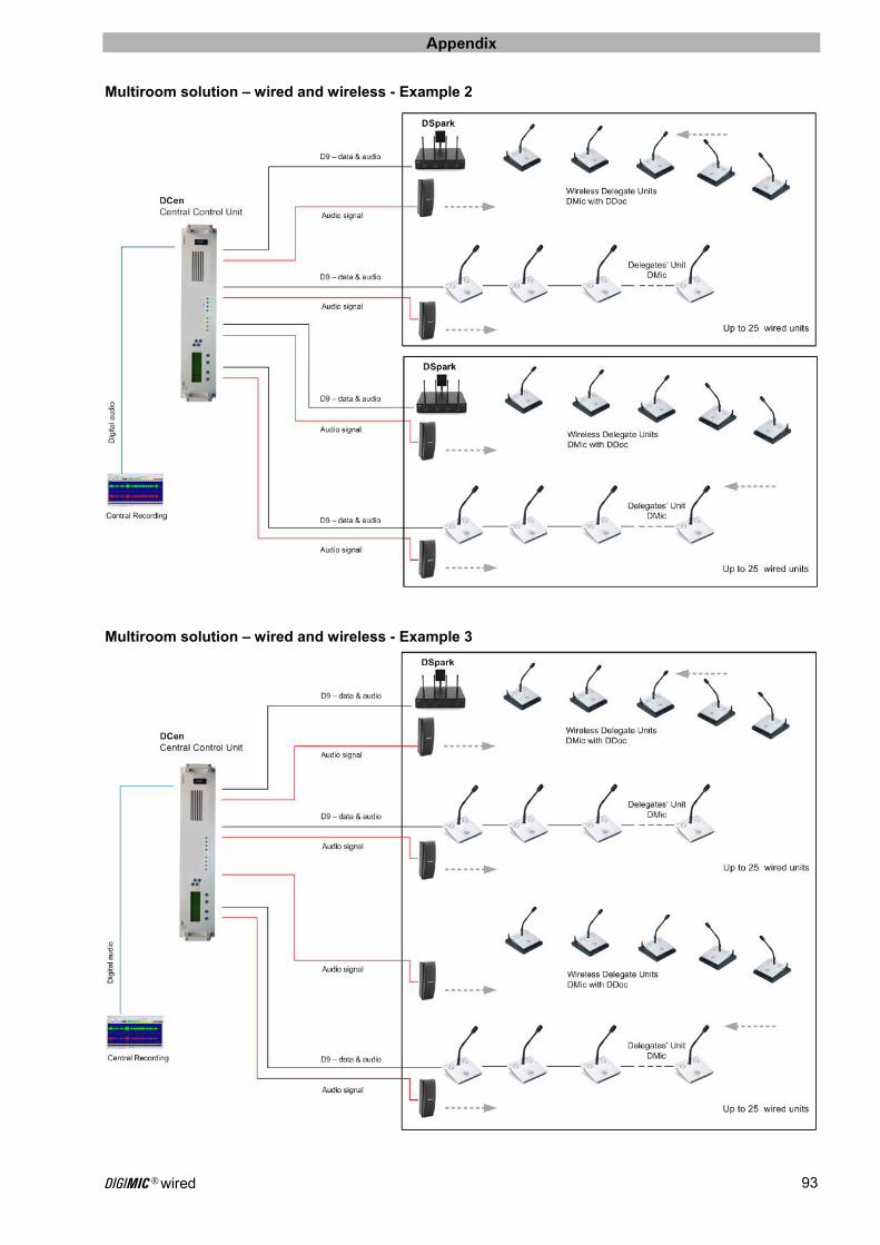
Appendix
DIGIMIC® wired 93
Multiroom solution – wired and wireless - Example 2
Multiroom solution – wired and wireless - Example 3

Appendix
DIGIMIC® wired 94
Technical Data
DCen Central Control Unit
Digital Audio • 48 kHz sample rate • 20 – 20,000 Hz frequency response • Resistant to RF, cell phone, Bluetooth, UMTS, Wi-Fi etc.
Audio device interfaces • ADAT input and output • AES/EBU input and output (XLR) • One analogue input (LINE-IN) XLR, transformer balanced, +4 dBu • Five analogue outputs XLR: 1 Master + 1 separate for each line, transformer balanced, +4 dBu
Control input and output • Two RS232 interfaces (CR9-socket) for microphone keyboard, media Control, camera systems, etc. • Network interface (TCP/IP) • Word clock input
Connection of units • UNITS L1 ... L4 (D9) up to 100 delegate units on four chains
Features • Mains switch for power on with indicator light • LC Display for menu controlled operation • 8 buttons for operation of the LCD menu • 4 green LEDs for indication of the accurate operating voltage at the four outputs L1-L4 • 4 yellow LEDs for indication of AF signal level • 4 independent power supplies - one for each communication line • 4 x 5 audio matrix allows sophisticated sound reinforcement and audio distribution • Outputs protected against short circuit and overload • Expandable for over 2.000 delegate units
Switching Power Supply • Mains power: (90 ... 250) VAC, (50 ... 60) Hz • Power consumption: 320VA max.
Mains cable Specific mains cables for different countries available: Australia: Part. No. 08.7820.AU United Kingdom: Part. No. 13.4220 USA, Canada, Japan: Part. No. 08.7820.US Germany: Part. No. 13.4220
Housing • 19", 2 HU, Aluminium, "silver" anodized • W x H x D: (433 x 88 x 330) mm approx. (17.0 x 3.5 x 13.0) inch (without mounting brackets) • Operating temperature range: 0 °C to + 50 °C
Weight • 4.5kg

Appendix
DIGIMIC® wired 95
RS-232 transmission protocol RS-232 (Recommended Standard 232) is a standard for serial binary data signals connecting between a DTE (Data Terminal Equipment) and a DCE (Data Circuit-terminating Equipment).
Pinouts The following table lists commonly-used RS-232 signals and pin assignments.
Signal Original DE-9
(TIA-574) EIA/TIA 561
Name Abbreviation DTE DCE
Common Ground
G 5 4
Protective Ground
PG - -
Transmitted Data
TxD ● 3 6
Received Data
RxD ● 2 5
Data Terminal Ready
DTR ● 4 3
Data Set Ready
DSR ● 6 1
Request To Send
RTS ● 7 8
Clear To Send
CTS ● 8 7
Carrier Detect
DCD ● 1 2
Ring Indicator
RI ● 9 1
Signals Transmitted Data (TxD)
Data sent from DTE to DCE.
Received Data (RxD)
Data sent from DCE to DTE.
Request To Send (RTS)
Asserted (set to logic 0, positive voltage) by DTE to prepare DCE to receive data. This may require action on the part of the DCE, e.g. transmitting a carrier or reversing the direction of a half-duplex channel. For the modern usage of "RTS/CTS handshaking," see the section of that name.
Ready To Receive (RTR)
Asserted by DTE to indicate to DCE that DTE is ready to receive data. If in use, this signal appears on the pin that would otherwise be used for Request To Send, and the DCE assumes that RTS is always asserted; see RTS/CTS handshaking for details.
Clear To Send (CTS)
Asserted by DCE to acknowledge RTS and allow DTE to transmit. This signaling was originally used with half-duplex modems and by slave terminals on multidrop lines: The DTE would raise RTS to indicate that it had data to send, and the modem would raise CTS to indicate that transmission was possible. For the modern usage of "RTS/CTS handshaking," see the section of that name.
Data Terminal Ready (DTR)
Asserted by DTE to indicate that it is ready to be connected. If the DCE is a modem, this may "wake up" the modem, bringing it out of a power saving mode. This behavior is seen quite often in modern PSTN and GSM modems. When this signal is de-asserted, the modem may return to its standby mode, immediately hanging up any calls in progress.
Data Set Ready (DSR)
Asserted by DCE to indicate the DCE is powered on and is ready to receive commands or data for transmission from the DTE. For example, if the DCE is a modem, DSR is asserted as soon as the modem is ready to receive dialing or other commands; DSR is not dependent on the connection to the remote DCE (see Data Carrier Detect for that function). If the DCE is not a modem (e.g. a null modem cable or other equipment), this signal should be permanently asserted (set to 0), possibly by a jumper to another signal.
Data Carrier Detect (DCD)
Asserted by DCE when a connection has been established with remote equipment.
Ring Indicator (RI)
Asserted by DCE when it detects a ring signal from the telephone line.
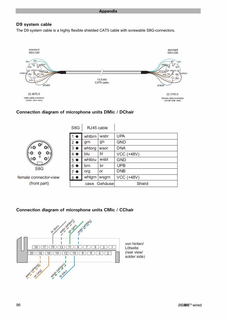
Appendix
DIGIMIC® wired 96
D9 system cable The D9 system cable is a highly flexible shielded CAT5 cable with screwable S8G-connectors.
Connection diagram of microphone units DMic / DChair
Connection diagram of microphone units CMic / CChair
1
2
3
4
5
6
7
8
9
10
11
12
13
14
15
16
17
18
19
20
wsbl (
whtblu
)
bl (b
lu)
gn (g
rn)
wsgn
(wht
grn)
wsbr (
whtbr
n)
br (b
rn)
or (o
rg)
wsor (
whtor
g)
von hinten/Lötseite(rear view/solder side)
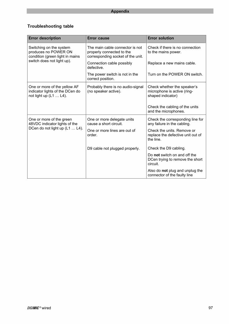
Appendix
DIGIMIC® wired 97
Troubleshooting table
Error description Error cause Error solution
Switching on the system produces no POWER ON condition (green light in mains switch does not light up).
The main cable connector is not properly connected to the corresponding socket of the unit.
Connection cable possibly defective.
The power switch is not in the correct position.
Check if there is no connection to the mains power.
Replace a new mains cable.
Turn on the POWER ON switch.
One or more of the yellow AF indicator lights of the DCen do not light up (L1 … L4).
Probably there is no audio-signal (no speaker active).
Check whether the speaker’s microphone is active (ring-shaped indicator)
Check the cabling of the units and the microphones.
One or more of the green 48VDC indicator lights of the DCen do not light up (L1 … L4).
One or more delegate units cause a short circuit.
One or more lines are out of order.
D9 cable not plugged properly.
Check the corresponding line for any failure in the cabling.
Check the units. Remove or replace the defective unit out of the line. Check the D9 cabling.
Do not switch on and off the DCen trying to remove the short circuit.
Also do not plug and unplug the connector of the faulty line
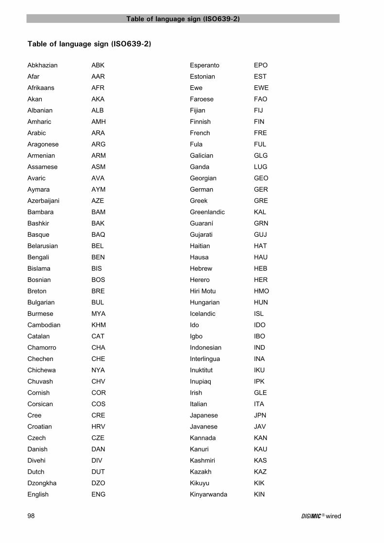
Table of language sign (ISO639-2)
DIGIMIC® wired 98
Table of language sign (ISO639-2)
Abkhazian ABK
Afar AAR
Afrikaans AFR
Akan AKA
Albanian ALB
Amharic AMH
Arabic ARA
Aragonese ARG
Armenian ARM
Assamese ASM
Avaric AVA
Aymara AYM
Azerbaijani AZE
Bambara BAM
Bashkir BAK
Basque BAQ
Belarusian BEL
Bengali BEN
Bislama BIS
Bosnian BOS
Breton BRE
Bulgarian BUL
Burmese MYA
Cambodian KHM
Catalan CAT
Chamorro CHA
Chechen CHE
Chichewa NYA
Chuvash CHV
Cornish COR
Corsican COS
Cree CRE
Croatian HRV
Czech CZE
Danish DAN
Divehi DIV
Dutch DUT
Dzongkha DZO
English ENG
Esperanto EPO
Estonian EST
Ewe EWE
Faroese FAO
Fijian FIJ
Finnish FIN
French FRE
Fula FUL
Galician GLG
Ganda LUG
Georgian GEO
German GER
Greek GRE
Greenlandic KAL
Guaraní GRN
Gujarati GUJ
Haitian HAT
Hausa HAU
Hebrew HEB
Herero HER
Hiri Motu HMO
Hungarian HUN
Icelandic ISL
Ido IDO
Igbo IBO
Indonesian IND
Interlingua INA
Inuktitut IKU
Inupiaq IPK
Irish GLE
Italian ITA
Japanese JPN
Javanese JAV
Kannada KAN
Kanuri KAU
Kashmiri KAS
Kazakh KAZ
Kikuyu KIK
Kinyarwanda KIN
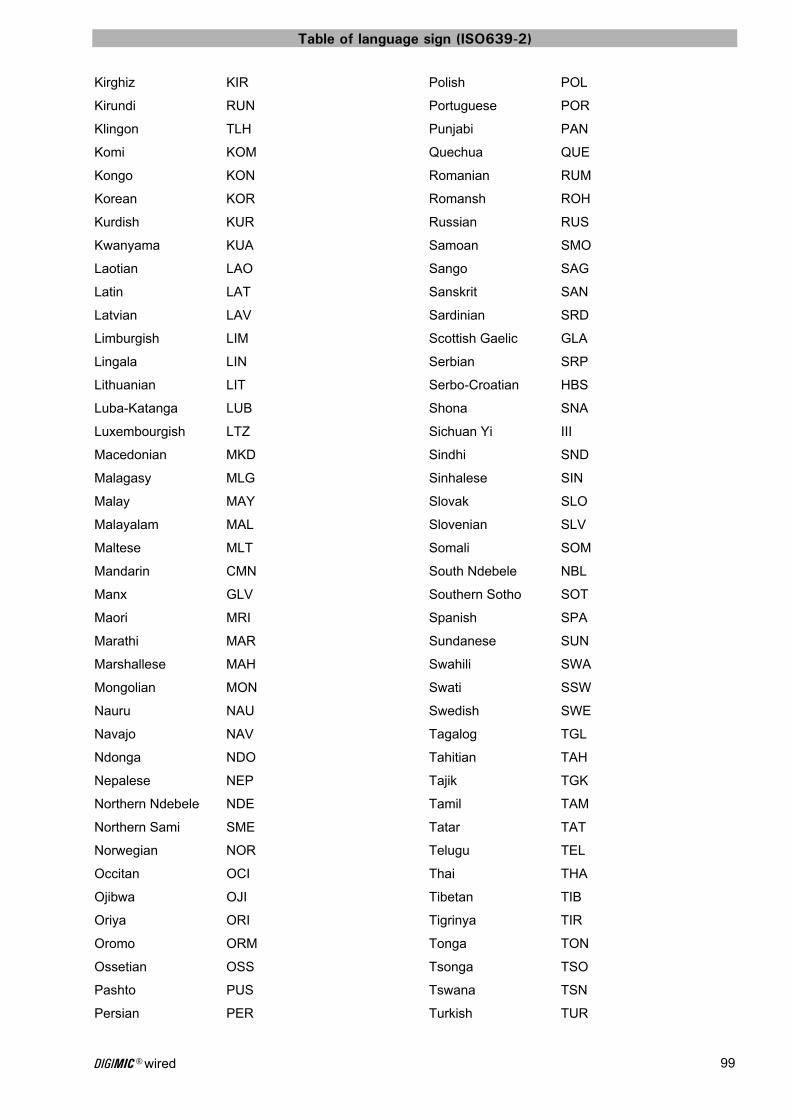
Table of language sign (ISO639-2)
DIGIMIC® wired 99
Kirghiz KIR
Kirundi RUN
Klingon TLH
Komi KOM
Kongo KON
Korean KOR
Kurdish KUR
Kwanyama KUA
Laotian LAO
Latin LAT
Latvian LAV
Limburgish LIM
Lingala LIN
Lithuanian LIT
Luba-Katanga LUB
Luxembourgish LTZ
Macedonian MKD
Malagasy MLG
Malay MAY
Malayalam MAL
Maltese MLT
Mandarin CMN
Manx GLV
Maori MRI
Marathi MAR
Marshallese MAH
Mongolian MON
Nauru NAU
Navajo NAV
Ndonga NDO
Nepalese NEP
Northern Ndebele NDE
Northern Sami SME
Norwegian NOR
Occitan OCI
Ojibwa OJI
Oriya ORI
Oromo ORM
Ossetian OSS
Pashto PUS
Persian PER
Polish POL
Portuguese POR
Punjabi PAN
Quechua QUE
Romanian RUM
Romansh ROH
Russian RUS
Samoan SMO
Sango SAG
Sanskrit SAN
Sardinian SRD
Scottish Gaelic GLA
Serbian SRP
Serbo-Croatian HBS
Shona SNA
Sichuan Yi III
Sindhi SND
Sinhalese SIN
Slovak SLO
Slovenian SLV
Somali SOM
South Ndebele NBL
Southern Sotho SOT
Spanish SPA
Sundanese SUN
Swahili SWA
Swati SSW
Swedish SWE
Tagalog TGL
Tahitian TAH
Tajik TGK
Tamil TAM
Tatar TAT
Telugu TEL
Thai THA
Tibetan TIB
Tigrinya TIR
Tonga TON
Tsonga TSO
Tswana TSN
Turkish TUR
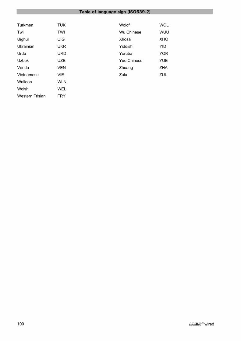
Table of language sign (ISO639-2)
DIGIMIC® wired 100
Turkmen TUK
Twi TWI
Uighur UIG
Ukrainian UKR
Urdu URD
Uzbek UZB
Venda VEN
Vietnamese VIE
Walloon WLN
Welsh WEL
Western Frisian FRY
Wolof WOL
Wu Chinese WUU
Xhosa XHO
Yiddish YID
Yoruba YOR
Yue Chinese YUE
Zhuang ZHA
Zulu ZUL

Templates for individual audio routing settings
DIGIMIC® wired 101
Templates for individual audio routing settings On the following pages you will have the possibility to type in your individual settings for your reference. L 1 bis 4 = Microphone-lines 1 to 4 (S8G) OR = Original R 1 bis 7 = Relais channels CC = Call Chairperson* CO = Call Operator* OUT 1 bis 4 = analog signal-out (XLR) AES/EBU = digital interface IN/OUT format AES/EBU (XLR) * CC / CO with priority! Setting 1
L 1 L 2 L 3 L 4 OR R 1 R 2 R 3 R 4 R 5 R 6 R 7 CC CO
Cha
irper
son
Del
egat
e
Cha
irper
son
Del
egat
e
Cha
irper
son
Del
egat
e
Cha
irper
son
Del
egat
e
OUT 1
OUT 2
OUT 3
OUT 4
OUT
AES/EBU links
AES/EBU rechts
Setting 2
L 1 L 2 L 3 L 4 OR R 1 R 2 R 3 R 4 R 5 R 6 R 7 CC CO
Cha
irper
son
Del
egat
e
Cha
irper
son
Del
egat
e
Cha
irper
son
Del
egat
e
Cha
irper
son
Del
egat
e
OUT 1
OUT 2
OUT 3
OUT 4
OUT
AES/EBU links
AES/EBU rechts
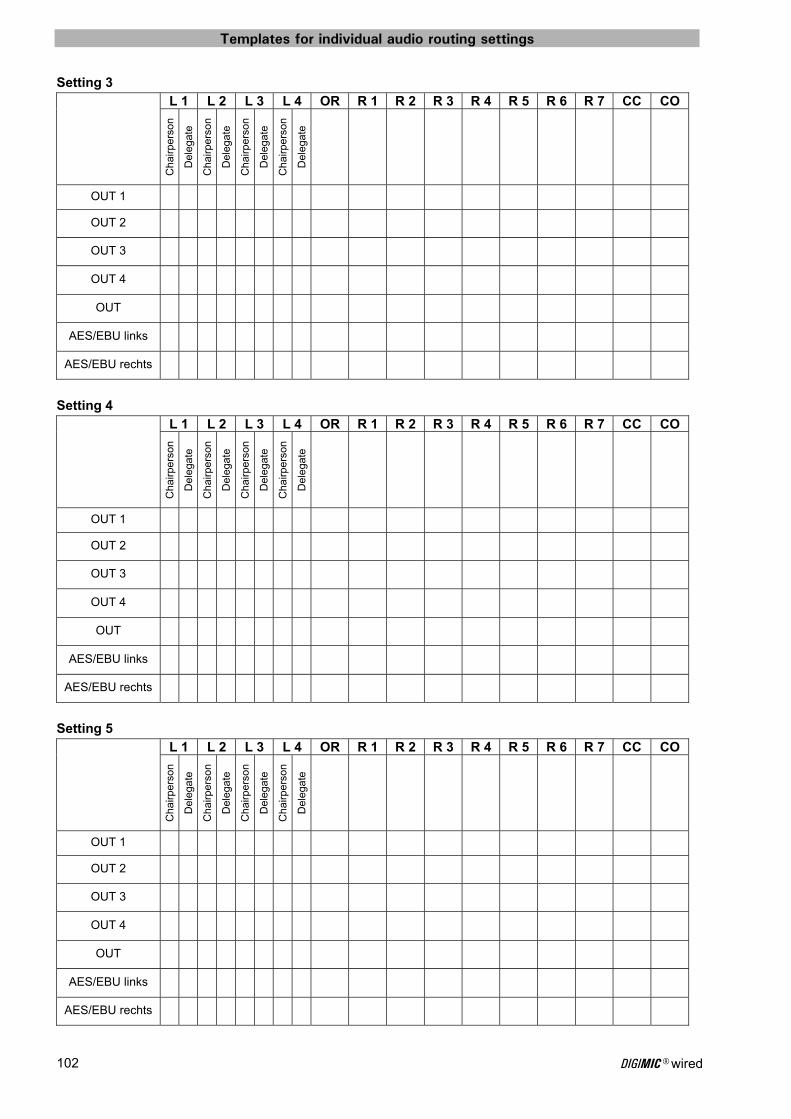
Templates for individual audio routing settings
DIGIMIC® wired 102
Setting 3
L 1 L 2 L 3 L 4 OR R 1 R 2 R 3 R 4 R 5 R 6 R 7 CC CO
Cha
irper
son
Del
egat
e
Cha
irper
son
Del
egat
e
Cha
irper
son
Del
egat
e
Cha
irper
son
Del
egat
e
OUT 1
OUT 2
OUT 3
OUT 4
OUT
AES/EBU links
AES/EBU rechts
Setting 4
L 1 L 2 L 3 L 4 OR R 1 R 2 R 3 R 4 R 5 R 6 R 7 CC CO
Cha
irper
son
Del
egat
e
Cha
irper
son
Del
egat
e
Cha
irper
son
Del
egat
e
Cha
irper
son
Del
egat
e
OUT 1
OUT 2
OUT 3
OUT 4
OUT
AES/EBU links
AES/EBU rechts
Setting 5
L 1 L 2 L 3 L 4 OR R 1 R 2 R 3 R 4 R 5 R 6 R 7 CC CO
Cha
irper
son
Del
egat
e
Cha
irper
son
Del
egat
e
Cha
irper
son
Del
egat
e
Cha
irper
son
Del
egat
e
OUT 1
OUT 2
OUT 3
OUT 4
OUT
AES/EBU links
AES/EBU rechts
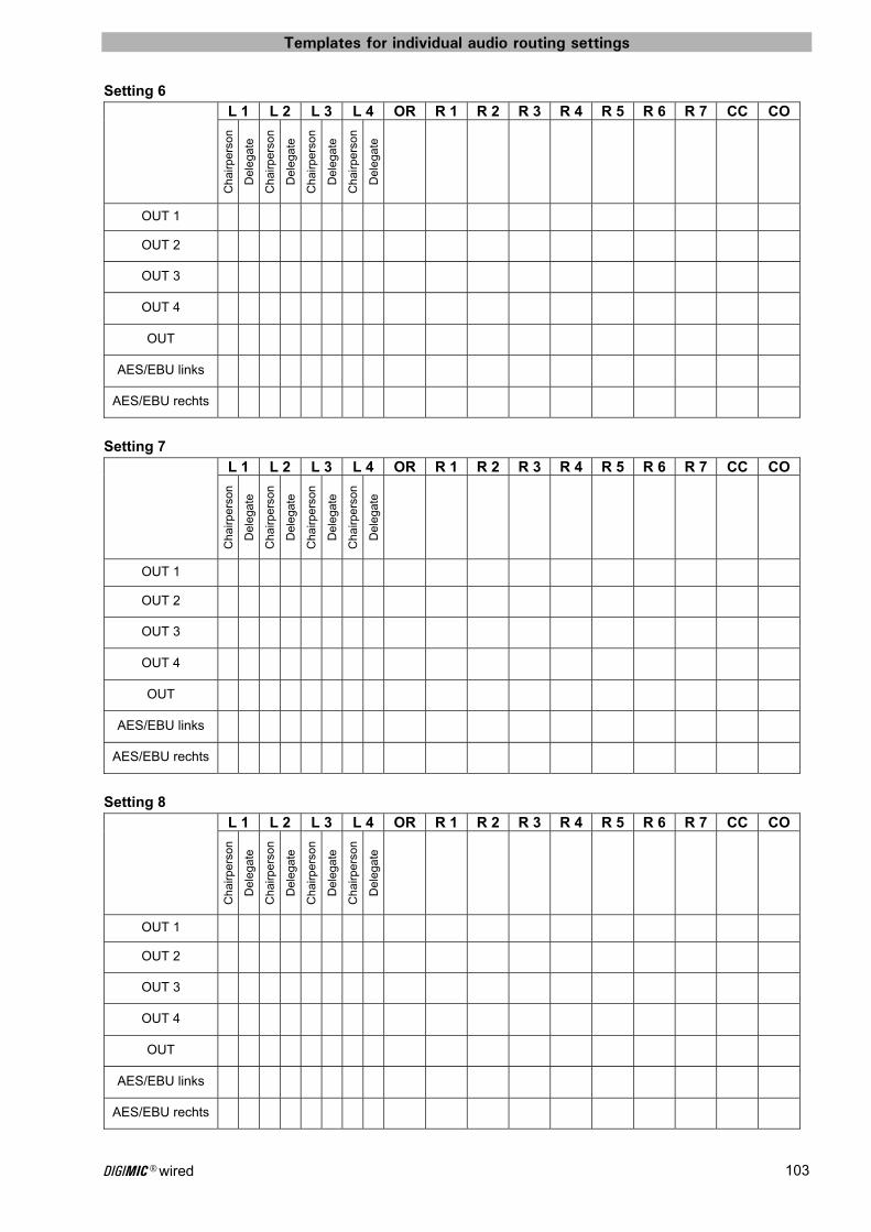
Templates for individual audio routing settings
DIGIMIC® wired 103
Setting 6
L 1 L 2 L 3 L 4 OR R 1 R 2 R 3 R 4 R 5 R 6 R 7 CC CO
Cha
irper
son
Del
egat
e
Cha
irper
son
Del
egat
e
Cha
irper
son
Del
egat
e
Cha
irper
son
Del
egat
e
OUT 1
OUT 2
OUT 3
OUT 4
OUT
AES/EBU links
AES/EBU rechts
Setting 7
L 1 L 2 L 3 L 4 OR R 1 R 2 R 3 R 4 R 5 R 6 R 7 CC CO
Cha
irper
son
Del
egat
e
Cha
irper
son
Del
egat
e
Cha
irper
son
Del
egat
e
Cha
irper
son
Del
egat
e
OUT 1
OUT 2
OUT 3
OUT 4
OUT
AES/EBU links
AES/EBU rechts
Setting 8
L 1 L 2 L 3 L 4 OR R 1 R 2 R 3 R 4 R 5 R 6 R 7 CC CO
Cha
irper
son
Del
egat
e
Cha
irper
son
Del
egat
e
Cha
irper
son
Del
egat
e
Cha
irper
son
Del
egat
e
OUT 1
OUT 2
OUT 3
OUT 4
OUT
AES/EBU links
AES/EBU rechts

Templates for individual audio routing settings
DIGIMIC® wired 104
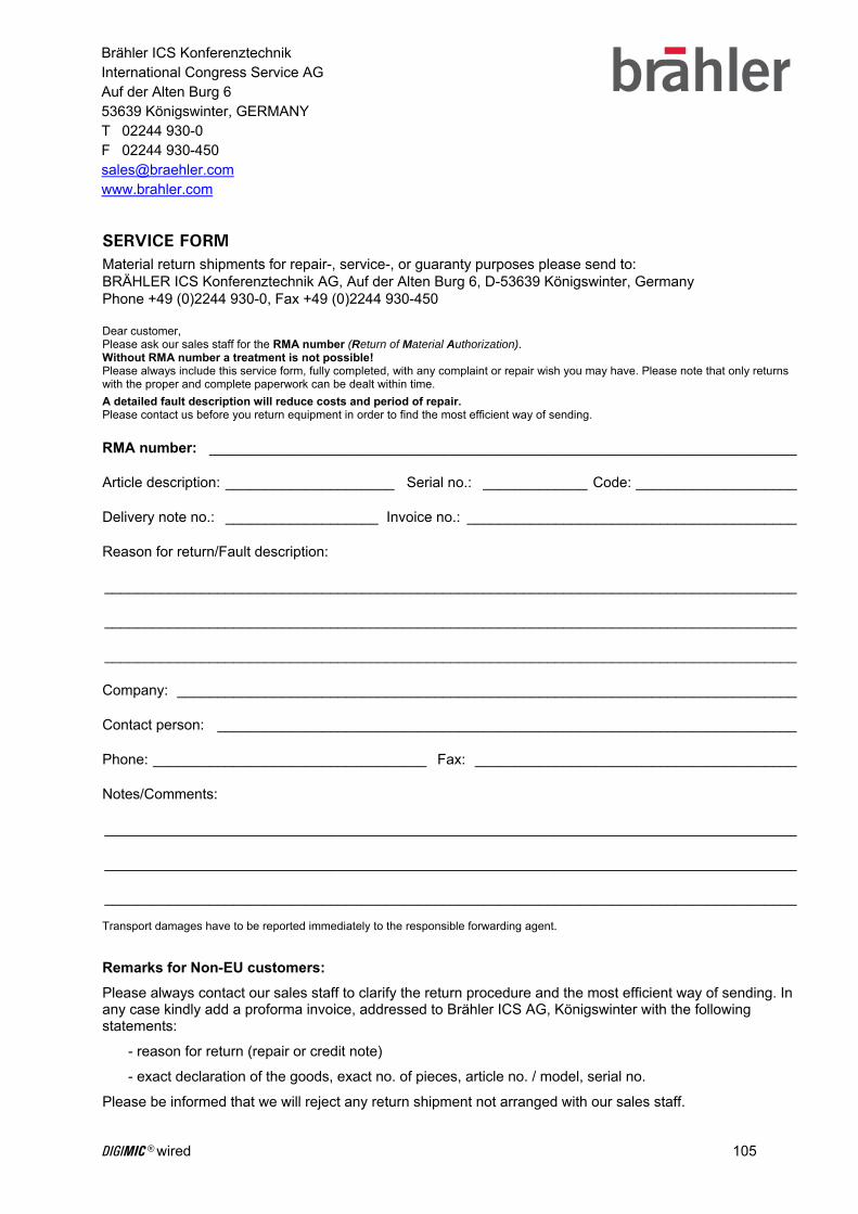
DIGIMIC® wired 105
SERVICE FORM Material return shipments for repair-, service-, or guaranty purposes please send to: BRÄHLER ICS Konferenztechnik AG, Auf der Alten Burg 6, D-53639 Königswinter, Germany Phone +49 (0)2244 930-0, Fax +49 (0)2244 930-450 Dear customer, Please ask our sales staff for the RMA number (Return of Material Authorization). Without RMA number a treatment is not possible! Please always include this service form, fully completed, with any complaint or repair wish you may have. Please note that only returns with the proper and complete paperwork can be dealt within time.
A detailed fault description will reduce costs and period of repair. Please contact us before you return equipment in order to find the most efficient way of sending.
RMA number: _________________________________________________________________________ Article description: _____________________ Serial no.: _____________ Code: ____________________ Delivery note no.: ___________________ Invoice no.: _________________________________________ Reason for return/Fault description: ______________________________________________________________________________________ ______________________________________________________________________________________ ______________________________________________________________________________________ Company: _____________________________________________________________________________ Contact person: ________________________________________________________________________ Phone: __________________________________ Fax: ________________________________________ Notes/Comments: ______________________________________________________________________________________ ______________________________________________________________________________________ ______________________________________________________________________________________ Transport damages have to be reported immediately to the responsible forwarding agent. Remarks for Non-EU customers:
Please always contact our sales staff to clarify the return procedure and the most efficient way of sending. In any case kindly add a proforma invoice, addressed to Brähler ICS AG, Königswinter with the following statements:
- reason for return (repair or credit note)
- exact declaration of the goods, exact no. of pieces, article no. / model, serial no.
Please be informed that we will reject any return shipment not arranged with our sales staff.
Brähler ICS Konferenztechnik International Congress Service AG Auf der Alten Burg 6 53639 Königswinter, GERMANY T 02244 930-0 F 02244 930-450 [email protected] www.brahler.com


Index
DIGIMIC® wired 107
Index
A About this manual 7 Active DELegate 36 ADAT 22, 30 ADAT sockets 32 Advanced Audio Routing Menu 55 AES/EBU 56 AES/EBU socket 31 Applications 19 Audio Boost 37, 73 Audio Matrix 52 Audio menu 51 Audio-Matrix Call Channels Menu 55 Audio-Matrix Interpreter Channels Menu 54 Audio-Matrix Line Channels Menu 54 AUTomatic conference mode 38 Automatic Numbering 43
B Booth Numbers Menu 59
C CChair and CMic connection 16 CChair Chairpersons Conference Unit classic 78 CChair controls 78 CE Conformity / FCC Statement 12 Central Control Unit DCen 27 CHAIRPERSON audio routing 24, 51 Chairperson-mute 62 Chairpersons Conference Unit DChair 76 CMic controls 79 CMic delegate unit classic 79 Conference Microphone TMD/01 82 Conference modes 17, 38 Conference parameters 36 Configuration File 70 Configuration menu 57 Connection diagram Display port delegates’ unit 96 Connection diagram S8G delegates’ unit 96 Contact information 109
D D9 system cable 96 DCen Central control 11, 18 DCen connection 15 DChair and DMic connection 15 DChair controls 76 DDol Channel Locking Menu 61 DEFAULT audio routing 22, 51 Default Gateway 49 Delegates´ Conference Unit DMic 77 DExt 80 DHCP Server 49 Display and operating buttons 33 DMic controls 77 Docking Unit DDoc 85 DSpark Factory defaults 72 DSpark Settings 66
E Editing of a network address 50
Erase Numbering 46 Ethernet line status 50 Extension power supply unit 80 External audio 14, 18, 30
F Factory defaults 74 Factory settings 18 frequency band setting 69
I Important safety information 9 Important safety instructions 8 INDIVIDUAL audio routing 26, 52 Individual Takeover Mode Menu 60 INTernal or EXTernal audio 37 Interpretation menu 58
K Key lock 18
L LAN connection 31 Language List Menu 58 LINE sockets L1 – L4 32 Line Status menu 39, 41 LINE-OUT socket 30
M MAC Address 50 Main menu 34 Mains cable 94 MANual conference mode 39 Manual Numbering 45 Menu locking 34 MicMute 63 Microphones 81 Multi-room application 87 Multi-Room Control 68 Multiroom solution – wired and wireless 92 Multiroom solution - wireless 90 Muting delegate units 36
N Network activity 37 Networking 48 Noise 63 Noise Level 63 noise to ... 63
O Operating keys 28 Operation of DCen 33 OR + 4CH routing 52 Overview of radio protocol data 69
Index
P Perm 36 Permanent or temporary muting 36 Priority 36 Protocol Selection 68
Q QuickStart 13
R Radio Transceiver Unit DSpark in combination with
DCen 84 Recall factory settings 18 Register Control 66 Register File 71 Reset Interpretation Values 61 RF Power 69 RS-232 Pinouts 95 RS232 serial interfaces 31
S Sample application 87 Seat Numbering 42 Seats Configuration 42 Service Form 105 Setting Storage Menu 74 Show Chairperson 46 Show/Edit VIPs 47 Software remote control DMicControl 20 Spectrum Setting 69
Standby Timeout 67 SysLog Server 49 System Info 71 System overview 14 System startup 17
T Tabelle der Sprachenkürzel 98 Takeover Mode 59 TCP/IP Address 48 Technical Data 94 Templates for individual audio routing settings 101 Time Server 49 TM58/6 Conference Microphone 81 TMD/01 Conference Microphone -shock mount 82 Transmission protocol APRON 84 Troubleshooting table 97
V VIP 36 Voice Activation 62 Volume control 36 VOX conference modes 62
W Wired system components 11 Wireless application 21 Wireless system components 11 Wireless system expansion 83 Wordclock 30
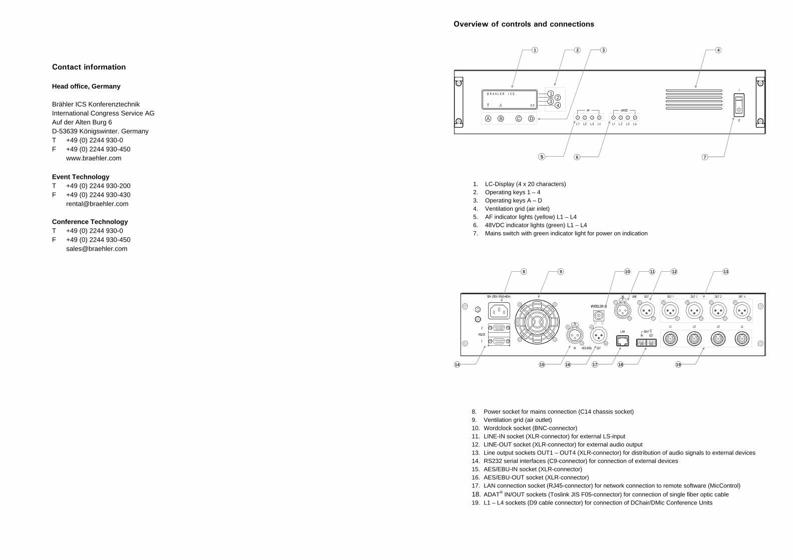
Contact information Head office, Germany Brähler ICS Konferenztechnik International Congress Service AG Auf der Alten Burg 6 D-53639 Königswinter. Germany T +49 (0) 2244 930-0 F +49 (0) 2244 930-450 www.braehler.com Event Technology T +49 (0) 2244 930-200 F +49 (0) 2244 930-430 [email protected] Conference Technology T +49 (0) 2244 930-0 F +49 (0) 2244 930-450 [email protected]
1. LC-Display (4 x 20 characters) 2. Operating keys 1 – 4 3. Operating keys A – D 4. Ventilation grid (air inlet) 5. AF indicator lights (yellow) L1 – L4 6. 48VDC indicator lights (green) L1 – L4 7. Mains switch with green indicator light for power on indication
8. Power socket for mains connection (C14 chassis socket) 9. Ventilation grid (air outlet) 10. Wordclock socket (BNC-connector) 11. LINE-IN socket (XLR-connector) for external LS-input 12. LINE-OUT socket (XLR-connector) for external audio output 13. Line output sockets OUT1 – OUT4 (XLR-connector) for distribution of audio signals to external devices 14. RS232 serial interfaces (C9-connector) for connection of external devices 15. AES/EBU-IN socket (XLR-connector) 16. AES/EBU-OUT socket (XLR-connector) 17. LAN connection socket (RJ45-connector) for network connection to remote software (MicControl) 18. ADAT® IN/OUT sockets (Toslink JIS F05-connector) for connection of single fiber optic cable 19. L1 – L4 sockets (D9 cable connector) for connection of DChair/DMic Conference Units
9
14 15 16 17 18 19
8 11 1310 12
Overview of controls and connections
5 6 7
41 2 3
12
34
A B C D
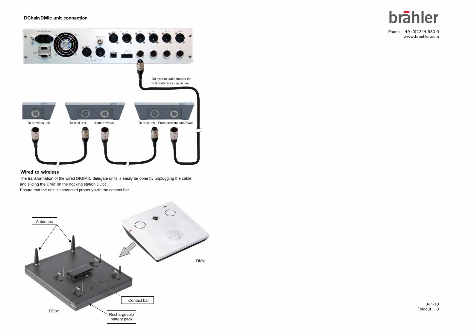
Phone +49 (0)2244 930-0
To
The traand sliEnsure
DChair/DMic unit connection
Wired
www.braehler.com
D9 system cable from/to the first conference unit in line
Jun-10 Foldout 1.3
From previous unit/DCen To next unit from previous To next unit previous unit
nsformation of the wired DIGIMIC delegate units is easily be done by unplugging the cable ding the DMic on the docking station DDoc. that the unit is connected properly with the contact bar.
Contact bar
Rec eable
Antennas
DMic
DDoc
to wireless
harg
pack battery
Related Documents
![REMOTE CONTROLLER (WIRED TYPE) - Планета Климата · REMOTE CONTROLLER (WIRED TYPE) [Original instructions] OPERATING MANUAL WIRED REMOTE CONTROLLER Keep this manual](https://static.cupdf.com/doc/110x72/5c9f331488c993502d8ceaa7/remote-controller-wired-type-remote-controller.jpg)