IMS01N17-E2 SRX DeviceNet Communication Instruction Manual RKC INSTRUMENT INC. ® Module Type Controller

Welcome message from author
This document is posted to help you gain knowledge. Please leave a comment to let me know what you think about it! Share it to your friends and learn new things together.
Transcript

IMS01N17-E2
SRXDeviceNet
CommunicationInstruction Manual
RKC INSTRUMENT INC. ®
Module Type Controller

All Rights Reserved, Copyright © 2004, RKC INSTRUMENT INC.
DeviceNet is a registered trademark of Open DeviceNet Vender Association, Inc. Modbus is a registered trademark of Schneider Electric. The name of each programmable controller (PLC) means the products of each manufacturer. Company names and product names used in this manual are the trademarks or registered trademarks of the respective companies. This product has been self-tested by RKC at DeviceNet Protocol Conformance Test Software Version A-17.

IMS01N17-E2 i-1
Thank you for purchasing this RKC product. In order to achieve maximum performance and ensure proper operation of your new instrument, carefully read all the instructions in this manual. Please place the manual in a convenient location for easy reference.
SYMBOLS
: This mark indicates important information on installation, handling and operating procedures.
: This mark indicates supplemental information on installation, handling and operating procedures.
: This mark indicates where additional information may be located.
An external protection device must be installed if failure of this instrument could result in damage to the instrument, equipment or injury to personnel.
All wiring must be completed before power is turned on to prevent electric shock, fire or damage to instrument and equipment.
This instrument must be used in accordance with the specifications to prevent fire or damage to instrument and equipment.
This instrument is not intended for use in locations subject to flammable or explosive gases.
Do not touch high-voltage connections such as power supply terminals, etc. to avoid electric shock.
RKC is not responsible if this instrument is repaired, modified or disassembled by other than factory-approved personnel. Malfunction can occur and warranty is void under these conditions.
CAUTION
: This mark indicates precautions that must be taken if there is danger of electricshock, fire, etc., which could result in loss of life or injury.
: This mark indicates that if these precautions and operating procedures are not
taken, damage to the instrument may result.
: This mark indicates that all precautions should be taken for safe usage.
WARNING
!
WARNING!

IMS01N17-E2 i-2
This product is intended for use with industrial machines, test and measuring equipment. (It is not designed for use with medical equipment and nuclear energy.)
This is a Class A instrument. In a domestic environment, this instrument may cause radio interference, in which case the user may be required to take additional measures.
This instrument is protected from electric shock by reinforced insulation. Provide reinforced insulation between the wire for the input signal and the wires for instrument power supply, source of power and loads.
Be sure to provide an appropriate surge control circuit respectively for the following: - If input/output or signal lines within the building are longer than 30 meters. - If input/output or signal lines leave the building, regardless the length.
This instrument is designed for installation in an enclosed instrumentation panel. All high-voltage connections such as power supply terminals must be enclosed in the instrumentation panel to avoid electric shock by operating personnel.
All precautions described in this manual should be taken to avoid damage to the instrument or equipment.
All wiring must be in accordance with local codes and regulations. All wiring must be completed before power is turned on to prevent electric shock, instrument failure, or incorrect action. The power must be turned off before repairing work for input break and output failure including replacement of sensor, contactor or SSR, and all wiring must be completed before power is turned on again.
To prevent instrument damage or failure, protect the power line and the input/output lines from high currents with a protection device such as fuse, circuit breaker, etc.
Prevent metal fragments or lead wire scraps from falling inside instrument case to avoid electric shock, fire or malfunction.
Tighten each terminal screw to the specified torque found in the manual to avoid electric shock, fire or malfunction.
For proper operation of this instrument, provide adequate ventilation for heat dispensation. Do not connect wires to unused terminals as this will interfere with proper operation of the instrument.
Turn off the power supply before cleaning the instrument. Do not use a volatile solvent such as paint thinner to clean the instrument. Deformation or discoloration will occur. Use a soft, dry cloth to remove stains from the instrument.
To avoid damage to instrument display, do not rub with an abrasive material or push front panel with a hard object.
When high alarm with hold action/re-hold action is used for Alarm function, alarm does not turn on while hold action is in operation. Take measures to prevent overheating which may occur if the control device fails.
NOTICE This manual assumes that the reader has a fundamental knowledge of the principles of electricity,
process control, computer technology and communications. The figures, diagrams and numeric values used in this manual are only for purpose of illustration. RKC is not responsible for any damage or injury that is caused as a result of using this instrument,
instrument failure or indirect damage. RKC is not responsible for any damage and/or injury resulting from the use of instruments made by
imitating this instrument. Periodic maintenance is required for safe and proper operation of this instrument. Some
components have a limited service life, or characteristics that change over time. Every effort has been made to ensure accuracy of all information contained herein. RKC makes no
warranty expressed or implied, with respect to the accuracy of the information. The information in this manual is subject to change without prior notice.
No portion of this document may be reprinted, modified, copied, transmitted, digitized, stored, processed or retrieved through any mechanical, electronic, optical or other means without prior written approval from RKC.
CAUTION

IMS01N17-E2 i-3
CONTENTS
Page 1. OUTLINE.............................................................................. 1 2. SPECIFICATIONS ................................................................ 3 3. SETTING PROCEDURE TO OPERATION .......................... 4 4. COMMUNICATION SETTING .............................................. 6
4.1 DeviceNet Communication Setting ..................................................................6 4.1.1 Node address setting ........................................................................................... 6 4.1.2 DeviceNet communication speed setting ............................................................. 7 4.1.3 DIP switch 1 setting.............................................................................................. 8 4.1.4 Internal data bus termination resistor setting ....................................................... 9
4.2 Module Address Setting ................................................................................10 4.3 Initializing Module ..........................................................................................12 4.4 Communication Environment Setting by Rotary Switch.................................13
5. WIRING ............................................................................... 16
5.1 Connection Outline of DeviceNet...................................................................16 5.2 Connection to DeviceNet ...............................................................................17
6. DeviceNet COMMUNICATIONS ........................................ 19
6.1 Features and Functionality ............................................................................19 6.2 Communication Method.................................................................................20
6.2.1 Polling I/O communication ................................................................................. 20 6.2.2 Explicit message communication ....................................................................... 30
6.3 Communication Items List .............................................................................35 7. COMMUNICATION DATA DESCRIPTION ........................ 44
7.1 Communication Data of TIO Module .............................................................45 7.1.1 Normal setting data items .................................................................................. 45 7.1.2 Program control data items ................................................................................ 71

IMS01N17-E2 i-4
Page 7.2 Communication Data of DI Module................................................................78 7.3 Communication Data of DO Module ..............................................................81
8. USAGE EXAMPLE ............................................................. 86
8.1 Handling Procedures .....................................................................................86 8.2 System Configuration ....................................................................................87 8.3 Hardware Setting...........................................................................................88 8.4 Sample Programs..........................................................................................89
8.4.1 Polling I/O communication (When the SYSMAC CJ) ......................................... 89 8.4.2 Explicit message communication (When the SYSMAC CJ)............................... 92
9. TROUBLESHOOTING........................................................ 98 APPENDIX A. DEVICE PROFILES..................................... 101
A.1 Basic Data...................................................................................................101 A.2 Object Mounting ..........................................................................................102
APPENDIX B. HOST COMMUNICATION........................... 112
B.1 Host Communication Specifications (DeviceNet Board) .............................112 B.2 Communication Setting ...............................................................................114 B.3 Communication Items List ...........................................................................116
APPENDIX C. HARDWARE................................................ 119
C.1 Terminal Configuration................................................................................119 C.2 Indication Lamp...........................................................................................120 C.3 Product Specifications ................................................................................122

IMS01N17-E2 1
1. OUTLINE
This manual describes DeviceNet specification, wiring, setting, and data instructions for the module type controller SRX.
The temperature control module for DeviceNet X-TIO-J (hereafter called the “X-TIO-J module”) can send and receive data to/from DeviceNet compatible programmable controller (hereafter called PLC) and personal computers by the DeviceNet that is a multivendor compatible open field network.
• On DeviceNet, a computer or a PLC is a master device, and the X-TIO-J module is a slave device.
• The X-TIO-J module has two communication ports to conduct host communication with DeviceNet. DeviceNet uses a DeviceNet connector. There are two connector types: open-style connector and micro-style connector.
For DeviceNet, refer to the website of ODVA (Open DeviceNet Vender Association). http://www.odva.org
For host communication using host communication terminals, refer to the APPENDIX B. HOST COMMUNICATION (P. 112) and the Module Type Controller SRX Communication Instruction Manual (IMS01N01-E ).
For specification, parts description and wiring of the X-TIO-J module, refer to the Temperature Control Module for DeviceNet X-TIO-J Instruction Manual (IMS01N16-E ).
System configuration example
DeviceNet
Master
SRX unit (Slave)
Temperature Control Module for DeviceNet
X-TIO-J
Programmable controller (PLC)
Usable modules: • Temperature control
module [Basic type]: X-TIO-A
• Temperature control module [Extension type]: X-TIO-B
• Digital input module: X-DI-A, X-DI-B
• Digital output module: X-DO-A, X-DI-B
(Up to 29 modules)

1. OUTLINE
IMS01N17-E2 2
EDS file The EDS file for the X-TIO-J module can be downloaded from the official RKC website: http://www.rkcinst.com/english/download/field_network.htm. Use the EDS file when recognizing the X-TIO-J module on the DeviceNet by using a configurator (tool used to set a master or slave environment on the DeviceNet) of each manufacturer.
For details, refer to Configuration Tool Instruction Manual of each company or Instruction Manual of the master product.

IMS01N17-E2 3
2. SPECIFICATIONS
DeviceNet communication Protocol: DeviceNet Supported connection: Polling I/O, Explicit message Connection method: Multi-drop connection, T-branch connection
(Terminating resistor is necessary) Communication speed: 125 kbps, 250 kbps, 500 kbps
(Communication speed can be selected with switch) Factory set value: 125 kbps
Communication length:
* The maximum of length between nodes
Maximum number of connection nodes: 64 (including master) Error control: CRC error, Node address (MAC ID) duplication check Conforms to DeviceNet specification: Volume I −Release2.0 Volume II −Release2.0 Device profile name: Generic Device Connection cable: Use the special cable Connector type: Open-style connector or Micro-style connector Termination resistor: 121 Ω, 1/4 W (externally connected)
For details of the device profile, refer to the APPENDIX A. DEVICE PROFILES (P. 101).
Maximum network length * Communication speed Thick trunk length Thin trunk length
Maximum drop length
Cumulative drop length
125 kbps 500 m 156 m or less250 kbps 250 m 100 m 6 m 78 m or less500 kbps 100 m 39 m or less

4 IMS01N17-E2
3. SETTING PROCEDURE TO OPERATION
Conduct necessary setting before operation according to the procedure described below.
DeviceNet communication setting
Set the node address and the communication speed of DeviceNet to SRX.
Refer to 4.1.1 Node address setting (P. 6) and 4.1.2 DeviceNet communication speed setting (P. 7).
The DIP switch sets the number of communication data items when conductingDeviceNet polling I/O communication and internal data bus termination resistance. In addition, set a module address of SRX with the module address settingswitch.
Wiring of SRX
Wire a power supply and input/output of SRX
For the X-TIO-J module, refer to APPENDIX C.1 Terminal Configuration (P. 119).For other modules, refer to the Instruction Manual of each module.
A
Refer to 4.1.3 DIP switch 1 setting (P. 8), 4.1.4 Internal data bus termination resistor setting (P. 9) and 4.2 Module Address Setting (P. 10).
The X-TIO-J module recognizes modules connected within the same unit byinitializing module.
Refer to 4.3 Initializing Module (P. 12).
Initializing module
Connect the SRX on DeviceNet.
Refer to 5. WIRING (P. 16).
For details of DeviceNet Network installation conditions and methods, refer to the instruction manual of the DeviceNet master unit or ODVA (Open DeviceNet Vender Association) website. http://www.odva.org
The number of communication data items can also be set via DeviceNetExplicit message communication or by the configuration tool. In this case, set itat the stage of the “Device parameter setting” procedure (P. 5).
Module setting
Connection of communication line

3. SETTING PROCEDURE TO OPERATION
IMS01N17-E2 5
Install the EDS file of SRX in a configuration tool of DeviceNet. The EDS file for the X-TIO-J module can be downloaded from the official RKC website: http://www.rkcinst.com/english/download/field_network.htm.
Data download
Programming
Create the sequence program.
Refer to 8.4 Sample Programs (P. 89).
Operation start
Power ON
To prevent malfunctioning, turn the power on in order of DeviceNet communication, slave and master.
When turn on the power supply of DeviceNet communication, slave includingSRX, and master (PLC etc.), the SRX performs as follows. 1. The X-TIO-J module starts collecting data on each module connected from
the time when the power is turned on. 2. The RUN lamp corresponding to indication lamp 2 flashed at very short
intervals. 3. After data collection is finished and DeviceNet communication becomes
enabled *, the RUN lamp keeps lighting. * Time required for enabling DeviceNet communication is about 15 seconds.
A
Refer to the Instruction Manual of Configuration Tool.
Set SRX communication parameters relating to polling I/O communication by using the DeviceNet configuration tool.
Device parameter setting
Refer to 6.2.1 Polling I/O communication (P. 20) and the Instruction Manual of Configuration Tool.
Download each device parameter created by the DeviceNet configuration tool to device on the actual network.
Refer to the Instruction Manual of Configuration Tool.
Installation of the EDS file

6 IMS01N17-E2
4. COMMUNICATION SETTING
Do not separate the module mainframe from the terminal base with the power turned on. If so, instrument failure may result. Set the following communication setting before operation. 4.1 DeviceNet Communication Setting 4.1.1 Node address setting To identify each device connected to the network, it is necessary to set a different address to each device (node). For the DeviceNet, as it is possible to connect up to 64 devices including a master to the network, node address (MAC ID) from 0 to 63 can be set. For this setting, use a small slotted screwdriver.
MSD: High-order digit setting(set value × 10)
Setting range: 0 to 63 (Factory set value: 63)
LSD: Low-order digit setting(set value × 1)
Node address setting switch
FAIL/RUNRX/TXEVENT1EVENT2EVENT3EVENT4
V+
CAN_
H Dr
ain
CAN_
L V−
NO
DE
ADD
RES
S M
SD
LSD
D
R
FAIL
RU
N
NS
MS
C
OM
. PO
RT
The above figure is open-style connector type. The figure of micro-style connector type is the same as an open-style connector type.
When any number exceeding 64 is set, the node address number becomes “63.”
To prevent electric shock or instrument failure, always turn off the power before setting the switch. To prevent electric shock or instrument failure, never touch any section other than those instructed in this manual.
WARNING!
CAUTION

4. COMMUNICATION SETTING
IMS01N17-E2 7
4.1.2 DeviceNet communication speed setting Set the communication speed of DeviceNet. For this setting, use a small slotted screwdriver.
Setting range: 0: 125 kbps 1: 250 kbps 2: 500 kbps
(Factory set value: 0)
DeviceNet communication speed setting switch
(DR or RATE *) FAIL/RUNRX/TXEVENT1EVENT2EVENT3EVENT4
V+
CAN_
H Dr
ain
CAN_
L V−
NO
DE
ADD
RES
S M
SD
LSD
D
R
FAIL
RU
N
NS
MS
CO
M. P
OR
T
The above figure is open-style connector type. The figure of micro-style connector type is the same as an open-style connector type.
When any number between 3 and 9 is set, the communication speed becomes “500 kbps.”
* Open-style connector type: DR Micro-style connector type: RATE

4. COMMUNICATION SETTING
IMS01N17-E2 8
4.1.3 DIP switch 1 setting With the DIP switch 1 which there is on the left side of module, set the number of communication data items when conducting DeviceNet polling I/O communication and termination resistor of internal data bus.
Switch No. 7: ON fixed (Do not change this one) Switch No. 3: OFF fixed (Do not change this one) Switch No. 1, 2 and 6 are used for the setting related to host communication on the DeviceNet side. When used only for DeviceNet communication, do not change the factory set values. For the host communication setting, refer to APPENDIX B.2 Communication Setting (P. 114).
Left side view
1 2 3 4 5 6 7 8
ON
1 2 3 4 5 6 7 8
ON ON
OFF
DIP switch 1
4 5 Number of communication data items when conducting polling I/O communication
OFF OFF 8 words ON OFF 26 words OFF ON 46 words ON ON 100 words
8 Internal data bus termination resistor setting
OFF Termination resistor OFF ON Termination resistor ON
The number of communication data items when conducting polling I/O communication can also be set via Explicit message communication, or by the configuration tool or rotary switch. However, when the number of communication data items is set via Explicit message communication, or by the configuration tool or rotary switch, the value set by the DIP switch may be ignored. For the number of communication data items when conducting polling I/O communication, refer to 4.4 Communication Environment Setting by Rotary Switch (P. 13),
Communication parameter setting by configuration tool (P. 24), Communication parameter setting by Explicit message communication (P. 32) or
7. COMMUNICATION DATA DESCRIPTION “Number of communication measured (or set) data items” (P. 70).
Factoryset value
Factoryset value

4. COMMUNICATION SETTING
IMS01N17-E2 9
4.1.4 Internal data bus termination resistor setting It is necessary to set the internal data bus termination resistor to the SRX unit. When connected X-TIO-J module alone
Turn on the internal data bus termination resistor in module of both sides.
No.8 of the DIP switch 1 (at the left side):ON (internal data bus termination resistorturned on)
X-TIO-J module
No.8 of the DIP switch 2 (at the right side):ON (internal data bus termination resistor turned on)
1 2 3 4 5 6 7 8
ON ON
OFF
DIP switch 1
1 2 3 4 5 6 7 8
ON ON
OFF
DIP switch 2
For the SRX unit
Turn on the internal data bus termination resistor in module of both ends. No.8 of the DIP switch 1 (at the left side): ON (internal data bus termination resistorturned on) Unit of module type
controller SRX
TIO module [extension type]DI module DO module
Turn on the internal data bus termination resistor (No. 8 of the DIP switch: ON) of this module.
Internal data bus1 2 3 4 5 6 7 8
ON ON
OFF
1 2 3 4 5 6 7 8
ON ON
OFF
No.8 of the DIP switch 2 (at the right side): OFF (internal data bus termination resistor turned off)
X-TIO-J module
1 2 3 4 5 6 7 8
ON ON
OFF

4. COMMUNICATION SETTING
IMS01N17-E2 10
4.2 Module Address Setting When using two or more modules, set the desired address to each module. Set the module address by module address setting switch of front of module. For this setting, use a small slotted screwdriver.
Do not set address “99 *.” Otherwise, malfunction may result.
* The DeviceNet board and the temperature control board are incorporated in the X-TIO-J module, and each board is assigned with the module address. The DeviceNet board address is fixed to “99.” Any address set by the module address setting switch corresponds to the temperature control board address.
Set the module address such that it is different to the other addresses on the same line. Otherwise, problems or malfunction may result.
Module address setting switch
High-order digit setting (set value × 10)
Setting range: 0 to 98 (Factory set value: 0)
Low-order digit setting (set value × 1)
FAIL/RUN RX/TX EVENT1 EVENT2 EVENT3 EVENT4
V+
CAN_
H Dr
ain
CAN_
L V−
NO
DE
ADD
RES
S M
SD
LSD
D
R
FAIL
RU
N
NS
MS
CO
M. P
OR
T
The above figure is open-style connector type. The figure of micro-style connector type is the same as an open-style connector type.

4. COMMUNICATION SETTING
IMS01N17-E2 11
Assignment of channels In DeviceNet communication, temperature control channel numbers are automatically determined in order starting from a smaller module address. Example: The assignment of channel numbers in the following system configuration is shown.
X-TIO-J module....................................................................1 Temperature control (TIO) module [expansion type]...........2 Digital input (DI) module ...................................................1 Digital output (DO) module..................................................1
X-TIO-J module Digital output (DO) module
Module address 0 1
Temperature control channel number on DeviceNet
Temperature control (TIO) module [expansion type]
Digital input (DI) module
CH1CH2
CH3CH4
CH1CH2
CH5CH6
2 4 3
Temperature control channel number of module
CH1 CH2
CH1 CH2
Module Type controller SRX
The number of temperature control channels which can be used in DeviceNet polling I/O communication is in accordance with the setting of “the number of communication channels.” If “the number of communication channels” is set to 5 in the above system configuration, no data in CH6 is accessible via polling I/O communication.
For the number of communication channels, refer to 4.4 Communication Environment Setting by Rotary Switch (P. 13), Communication parameter setting by configuration tool (P. 24), Communication parameter setting by Explicit message communication (P. 32) or APPENDIX B. HOST COMMUNICATION (P. 112).

4. COMMUNICATION SETTING
IMS01N17-E2 12
4.3 Initializing Module Conduct this initialization when the power is turned on for the first time or the module configuration is changed.
The X-TIO-J module recognizes modules connected within the same unit by initializing module. Initialize module by using the “Node address setting switch” and the “DeviceNet communication speed setting switch” on the X-TIO-J module.
MSD
LSD
Node address setting switch
DeviceNet communication speed setting switch
DR or
RATE *
FAIL/RUNRX/TX EVENT1EVENT2EVENT3EVTNT4
V+
CAN_
H Dr
ain
CAN_
L V−
NO
DE
ADD
RES
S M
SD
LSD
D
R
FAI
RU N
S
MS
CO
M. P
OR
T
5 4 3 210
98765 4 3 21
098765 4 3 21
09876
Setting procedure 1. Turn off the power supply.
2. Before initializing module, record the switch positions of node address setting switch and
DeviceNet communication speed setting switch. (When this module is used for the first time, no recording is required.)
3. Set all the values of a node address setting
switch and a DeviceNet communication speed setting switch to “7.”
4. The module starts being initialized with the power turned on. The RUN lamp flashes quickly while the module is being initialized. It takes about 15 seconds for initialization.
5. The RUN lamp is turned on if initializing module is completed.
6. Turn off the power supply, and return the switch positions of node address setting switch and DeviceNet communication speed setting switch to the positions already recorded.
RUN lamp Rapid flashing
Node address setting switch and
DeviceNet communication speed setting switch
5 4 3 210
9876
* Open-style connector type: DR Micro-style connector type: RATE

4. COMMUNICATION SETTING
IMS01N17-E2 13
4.4 Communication Environment Setting by Rotary Switch Set communication environment of polling I/O communication of DeviceNet and host communication by using the “Node address setting switch” and the “DeviceNet communication speed setting switch” which are the rotary switch of the X-TIO-J module
MSD
LSD
Node address setting switch
DeviceNet communication speed setting switch
DR or
RATE *
FAIL/RUNRX/TX EVENT1EVENT2EVENT3EVTNT4
V+
CAN_
H Dr
ain
CAN_
L V−
NO
DE
ADD
RES
S M
SD
LSD
D
R
FAI
RU N
S
MS
CO
M. P
OR
T
5 4 3 210
98765 4 3 21
098765 4 3 21
09876
Setting procedure 1. Turn off the power supply.
2. Before initializing module, record the switch positions of node address setting switch and
DeviceNet communication speed setting switch. (When this module is used for the first time, no recording is required.)
3. Set all the values of a node address setting
switch and a DeviceNet communication speed setting switch to “9.”
4. Turning on the power sets the module to the communication environment setting mode. If set to the communication environment setting mode, the RUN lamp goes off and the FAIL lamp flashes.
5. Select a setting item number with MSD of the node address setting switch, and set data with LSD of the node address setting switch.
Refer to List of communication environment setting items (P. 15).
6. Set the DeviceNet communication speed setting switch in the order of “9,” “0” and “1.” The RUN lamp turns on and then it turns off after registration of the set data is complete (after a lapse about 3 seconds).
Continued on the next page.
Node address setting switch and
DeviceNet communication speed setting switch
FAIL lamp (red) flashing
RUN lampturns off
5 4 3 210
9876
* Open-style connector type: DR Micro-style connector type: RATE

4. COMMUNICATION SETTING
IMS01N17-E2 14
Continued from the previous page.
7. Repeat the steps from 5. to 6. of previous page, and set other setting items. [Example] When set the number of polling I/O communication channel to a 18 channel • Set “2” * by MSD of the node address setting switch. • Set “3” * (3 × 6 = 18) by LSD of the node address setting switch. • Return the DeviceNet communication speed setting switch to “0.” And set to “1” again.
The RUN lamp turns on and then it turns off after registration of the set data is complete (after a lapse about 3 seconds).
* Refer to List of communication environment setting items (P. 15).
8. First check that the RUN lamp goes off, and then turn off the power.
9. Return the switch positions of node address setting switch and DeviceNet communication speed setting switch to the positions already recorded.
10. Turn on the power again.
The set data valid if the power is turned on again.
Node address setting switch
MSD
Set “2”
Node address setting switch
LSD
Set “3”
DeviceNet communicationspeed setting switch
DR or RATE
「0」→「1」
5 4 3 210
9876
5 4 3 210
9876
5 4 3 210
9876

4. COMMUNICATION SETTING
IMS01N17-E2 15
List of communication environment setting items
Node address setting switch MSD Node address setting switch LSD No. Setting item Data range
Factory set value
0 Unused
1 Unused
Do not set this one ⎯
2 Number of polling I/O communication channels
0: 2 channels 1 to 8: 6 to 48 channels (= set value × 6) 9: 60 channels
Set the number of temperature control channel of SRX communicating by polling I/O communication.
10 channels
3 Host communication transmission transfer time
0 to 8: 0 to 80 ms (= set value × 10) 9: 255 ms
Set the standby time until the X-TIO-J module starts sending data after receiving data from the host computer.
255 ms
4 Modbus data interval extension time
0 to 8: 0 to 80 ms (= set value × 10) 9: 255 ms
Extend data time interval in Modbus.
255 ms
5 Polling I/O communication Number of communication measured data items (IN)
0 to 9: 0 to 90 words (= set value × 10)
Set the number of measured data items (IN) (number of words) communicating via polling I/O communication.
0
6 Polling I/O communication Number of communication set data items (OUT)
0 to 9: 0 to 90 words (= set value × 10)
Set the number of set data items (OUT) (number of words) communicating via polling I/O communication.
0
7 Unused
8 Unused
Do not set this one. ⎯
9 Set value initialization 0 to 8: Unused 9: Communication environment setting initialization execution
Initialize each communication environment setting data item which can be set by the rotary switch.
⎯

16 IMS01N17-E2
5. WIRING
5.1 Connection Outline of DeviceNet The following diagram shows the configuration of a DeviceNet network.
Network configuration example • Nodes
There are two kinds of nodes of master and slave in DeviceNet. The master and slaves can be connected at any location in the network.
• Trunk/Drop lines The trunk line refers to the cable that has Terminating Resistors on both ends. Cables branching from the trunk line are known as drop lines. Use the DeviceNet communication cable (thick or thin cable) for Trunk/Drop lines.
• Connection methods Two methods can be used to connect DeviceNet nodes: The T-branch method and the multi-drop method. With the T-branch method, the node is connected to a drop line created with a T-branch Tap. With the multi-drop method, the node is directly connected to the trunk line or the drop line.
• Terminating resistors Install terminating resistors to both ends of a trunk line in DeviceNet. Specification of terminating resistor: 121 Ω, ±1 %, 1/4 W (Metal film resistance)
• Communications power supplies To use DeviceNet, connect a communications power supply (24 V DC) to the communications connector of each node with a cable.
Communicationpower
Power supply tap
T-branchtap
Trunk line
Terminating resistor Node
Drop line Node
Node Node
Terminatingresistor
Trunk line
Trunkline
Trunkline
Trunk line
T-branchtap
Drop line
Drop line
To prevent electric shock or instrument failure, turn off the power before connecting or disconnecting the instrument and peripheral equipment. Make sure that the wiring is correct before applying power to the instrument.
WARNING!

5. WIRING
IMS01N17-E2 17
• Communication length
* The maximum of length between nodes
For details of DeviceNet Network installation conditions and methods, refer to the instruction manual of the DeviceNet master unit or DeviceNet Specifications. DeviceNet specifications are available at ODVA (Open DeviceNet Vender Association, http://www.odva.org).
5.2 Connection to DeviceNet Open-style connector
DeviceNet connector open-style connector
(COM. PORT)
1: V− 2: CAN_L3: Drain 4: CAN_H5: V+
Communication terminal number and signal details Pin No. Signal name Symbol Cable color
1 Power supply, minus (−) V− Black 2 Communication data, low CAN_L Blue 3 Shield Drain ⎯ 4 Communication data, high CAN_H White 5 Power supply, plus (+) V+ Red
Connection plugs (recommended models)
SRXDN-01 (Sold separately) MSTB2.5/5-STF-5.08AUM (PHOENIX CONTACT, Inc.) or equal
Multi-drop type (recommended models): TMSTBP2.5/5-STF-5.08AUM (PHOENIX CONTACT, Inc.)
Maximum network length * Communication speed Thick trunk length Thin trunk length
Maximum drop length
Cumulative drop length
125 kbps 500 m 156 m or less250 kbps 250 m 100 m 6 m 78 m or less 500 kbps 100 m 39 m or less
5. WIRING
18 IMS01N17-E2
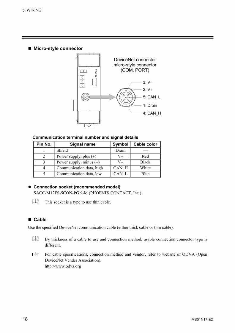
Micro-style connector
DeviceNet connector micro-style connector
(COM. PORT)
1: Drain
2: V+
3: V−
4: CAN_H
5: CAN_L
Communication terminal number and signal details Pin No. Signal name Symbol Cable color
1 Shield Drain ⎯ 2 Power supply, plus (+) V+ Red 3 Power supply, minus (−) V− Black 4 Communication data, high CAN_H White 5 Communication data, low CAN_L Blue
Connection socket (recommended model)
SACC-M12FS-5CON-PG 9-M (PHOENIX CONTACT, Inc.)
This socket is a type to use thin cable. Cable
Use the specified DeviceNet communication cable (either thick cable or thin cable).
By thickness of a cable to use and connection method, usable connection connector type is different.
For cable specifications, connection method and vendor, refer to website of ODVA (Open DeviceNet Vender Association). http://www.odva.org

IMS01N17-E2 19
6. DeviceNet COMMUNICATIONS
6.1 Features and Functionality One DeviceNet Network can have a maximum of 64 Media Access Control Identifiers (MAC ID:
Node address).
Network length changes with communication speed.
Maximum network length * Communication speed Thick trunk length Thin trunk length
Maximum drop length
Cumulative drop length
125 kbps 500 m 156 m or less 250 kbps 250 m 100 m 6 m 78 m or less 500 kbps 100 m 39 m or less
* Maximum distance between nodes
Install terminating resistors to both ends of a trunk line in DeviceNet. Specification of terminating resistor: 121 Ω, ±1 %, 1/4 W (Metal film resistance)
A DeviceNet node is modeled as a collection of objects. The object model provides a template for organizing and implementing the Attributes (data), Services and Behaviors of the components of a DeviceNet product. This model has represented the construction of address designation to consist of four levels of Node address (MAC ID), Object class ID, Instance ID and Attribute ID. An address of this 4 level is used as an identification factor of data in Explicit message communication.
Address Lowest Highest
Node 0 63 Object class 1 65535
Instance 0 65535 Attribute 1 255
DeviceNet incorporates CAN (Controller Area Network). CAN defines the syntax or form of the data movement. Data on DeviceNet is transmitted using CAN data frame.
Identifier Control Data (0 to 8 bytes) CRC
CAN data frame
For details on the communication specification of DeviceNet, refer to DeviceNet specifications. DeviceNet specifications are available from ODVA (Open DeviceNet Vender Association, http://www.odva.org).
ACK RTR Bit
Start of Frame End of Frame
6. DeviceNet COMMUNICATIONS
20 IMS01N17-E2
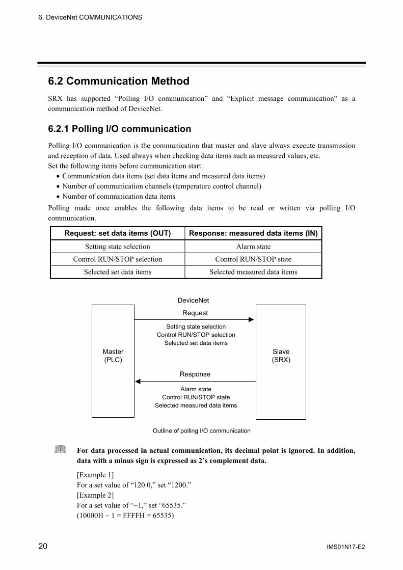
6.2 Communication Method SRX has supported “Polling I/O communication” and “Explicit message communication” as a communication method of DeviceNet. 6.2.1 Polling I/O communication Polling I/O communication is the communication that master and slave always execute transmission and reception of data. Used always when checking data items such as measured values, etc. Set the following items before communication start.
• Communication data items (set data items and measured data items) • Number of communication channels (temperature control channel) • Number of communication data items
Polling made once enables the following data items to be read or written via polling I/O communication.
Request: set data items (OUT) Response: measured data items (IN)
Setting state selection Alarm state
Control RUN/STOP selection Control RUN/STOP state
Selected set data items Selected measured data items
Outline of polling I/O communication
For data processed in actual communication, its decimal point is ignored. In addition, data with a minus sign is expressed as 2’s complement data.
[Example 1] For a set value of “120.0,” set “1200.” [Example 2] For a set value of “−1,” set “65535.” (10000H − 1 = FFFFH = 65535)
Slave (SRX)
Master (PLC)
Request
Setting state selection Control RUN/STOP selection
Selected set data items
Response
DeviceNet
Alarm state Control RUN/STOP state
Selected measured data items

6. DeviceNet COMMUNICATIONS
IMS01N17-E2 21
Data to send from a master [Request: set data items (OUT)] A master transmits data of the following for slave (SRX).
Communication data (set data items) contents
No. Items Data range Factory set value
1 Setting state selection (channel 1 to 16)
2 Setting state selection (channel 17 to 32)
3 Setting state selection (channel 33 to 48)
4 Setting state selection (channel 49 to 60)
Bit data The following channels correspond to Bit 0 to Bit 15 of communication data No. 1 to 4. No. 1: Bit 0 to Bit 15・・・channel 1 to 16 No. 2: Bit 0 to Bit 15・・・channel 17 to 32 No. 3: Bit 0 to Bit 15・・・channel 33 to 48 No. 4: Bit 0 to Bit 15・・・channel 49 to 60 Data 0: Setting disabled 1: Setting enabled [Decimal number: 0 to 65535]
0
5 Control RUN/STOP selection (module 1 to 16) [Data of each module]
6 Control RUN/STOP selection (module 17 to 32) [Data of each module]
Bit data The following modules correspond to Bit 0 to Bit 15 of communication data No. 5 and 6. No. 5: Bit 0 to Bit 15・・・module 1 to 16 No. 6: Bit 0 to Bit 15・・・module 17 to 32 Data 0: STOP 1: RUN [Decimal number: 0 to 65535]
Same as control RUN/STOP state of SRX
On and
after 7
Selected set data items Set data items are set by the configuration tool or via Explicit message communication are assigned by the number of channels similarly set.
Same as the range of set data items selected Same as the factory set value of set data items selected
Communication data No. 1 to 6 (corresponding to 6 words) are fixed communication data items. In order to validate data items on and after communication data No. 7, it is necessary to set the relevant channel for setting state selection of communication data No. 1 to 4 to “1: Setting enabled.” However, this is applied only to TIO module communication data items.
For the setting method of the number of communication data items, refer to 4.1.3 DIP switch 1 setting (P. 8), 4.4 Communication Environment Setting by Rotary Switch (P. 13),
Communication parameter setting by configuration tool (P. 24) or Communication parameter setting by Explicit message communication (P. 32) For the communication data items setting by configuration tool, refer to Communication parameter setting by configuration tool (P. 24). In addition, for the communication data items setting by Explicit message communication, refer to Communication parameter setting by Explicit message communication (P. 32).
For contents of set data items, refer to 6.3 Communication Items List (P. 35).

6. DeviceNet COMMUNICATIONS
22 IMS01N17-E2
Data which a master receives [Response: measured data items (IN)] A master transmits data of the following for slave (SRX).
Communication data (measured data items) contents
No. Items Data range
1 Alarm state (channel 1 to 16)
2 Alarm state (channel 17 to 32)
3 Alarm state (channel 33 to 48)
4 Alarm state (channel 49 to 60)
Bit data The following channels correspond to Bit 0 to Bit 15 of communication data No. 1 to 4. No. 1: Bit 0 to Bit 15・・・channel 1 to 16 No. 2: Bit 0 to Bit 15・・・channel 17 to 32 No. 3: Bit 0 to Bit 15・・・channel 33 to 48 No. 4: Bit 0 to Bit 15・・・channel 49 to 60 Data 0: Alarm OFF 1: Alarm ON Set to “1” if any one of burnout, event 1, event 2, heater break alarm (HBA) and control loop break alarm (LBA) is turned on in each channel. [Decimal number: 0 to 65535]
5 Control RUN/STOP state (module 1 to 16) [Data of each module]
6 Control RUN/STOP state (module 17 to 32) [Data of each module]
Bit data The following modules correspond to Bit 0 to Bit 15 of communication data No. 5 and 6. No. 5: Bit 0 to Bit 15・・・module 1 to 16 No. 6: Bit 0 to Bit 15・・・module 17 to 32 Data 0: RUN 1: STOP [Decimal number: 0 to 65535]
On and
after 7
Selected measured data items Measured data items set by the configuration tool or via Explicit message communication are assigned by the number of channels similarly set.
Same as the range of measured data items selected
Communication data No. 1 to 6 (corresponding to 6 words) are fixed communication data items.
For the setting method of the number of communication data items, refer to 4.1.3 DIP switch 1 setting (P. 8), 4.4 Communication Environment Setting by Rotary Switch (P. 13),
Communication parameter setting by configuration tool (P. 24) or Communication parameter setting by Explicit message communication (P. 32)
For the communication data items setting by configuration tool, refer to Communication parameter setting by configuration tool (P. 24). In addition, for the communication data items setting by Explicit message communication, refer to Communication parameter setting by Explicit message communication (P. 32).
For contents of measured data items, refer to 6.3 Communication Items List (P. 35).

6. DeviceNet COMMUNICATIONS
IMS01N17-E2 23
Number of communication data items setting by DIP switch Use the switch No. 4 and 5 of the DIP switch 1 which there is on the left side of X-TIO-J module, sets the number of communication data items when conducting polling I/O communication.
1 2 3 4 5 6 7 8
ON
1 2 3 4 5 6 7 8
ON ON
OFF
Left side view
DIP switch 1
4 5 Number of communication data itemsOFF OFF 8 words ON OFF 26 words OFF ON 46 words ON ON 100 words
Switch No. 7: ON fixed (Do not change this one) Switch No. 3: OFF fixed (Do not change this one)
The number of communication data items can also be set via Explicit message communication, or by the configuration tool or rotary switch. However, when the number of communication data items is set via Explicit message communication, or by the configuration tool or rotary switch, the value set by the DIP switch may be ignored.
For the number of communication data items, refer to 4.4 Communication Environment Setting by Rotary Switch (P. 13),
Communication parameter setting by configuration tool (P. 24), Communication parameter setting by Explicit message communication (P. 32) or
7. COMMUNICATION DATA DESCRIPTION “Number of communication measured (or set) data items” (P. 70).
For switch No. 1, 2, 6, and 8, refer to 4.1.3 DIP switch 1 setting (P. 8) and 4.1.4 Internal data bus termination resistor setting (P. 9).
Factory set value

6. DeviceNet COMMUNICATIONS
24 IMS01N17-E2
Communication parameter setting by configuration tool Set the following items with the configuration tool.
• Communication data items (set data items and measured data items) • Number of communication channels (temperature control channel) • Number of communication data items
Time-out may occur if trying to read any SRX parameter from the configuration tool while in polling I/O communication between the master station and SRX. When reading or setting the parameters by the configuration tool, stop polling I/O at the master station.
For operation of the configuration tool, refer to each configuration tool instruction manual.
It is also possible to set communication data items, the number of communication channels and the number of communication data items using Explicit message communication. For details, refer to Communication parameter setting by Explicit message communication (P. 32).
Setting procedure 1. Connect a personal computer installed with the configuration tool to the SRX via DeviceNet.
2. Install the EDS file attached to SRX in the configuration tool.
3. Open a parameter setting screen of SRX after having added SRX to network configuration by
using a configuration tool.
< Reference screen 1: Configuration tool made by OMRON >
Continued on the next page.
Set attribute ID of the communication item, the number of communication channel and the number of communication data.

6. DeviceNet COMMUNICATIONS
IMS01N17-E2 25
Continued from the previous page.
<Reference screen 2: Configuration tool made by Rockwell>
4. Sets the attribute ID of communication data items, the number of communication channels and the number of communication data items with a parameter setting screen.
“The number of communication channels” corresponds to number of temperature control channels of the SRX communicating via polling I/O communication.
For the attribute ID of communication data items, refer to 6.3 Communication Items List (P. 35).
Set attribute ID of the communication item, the number of communication channel and the number of communication data.

6. DeviceNet COMMUNICATIONS
26 IMS01N17-E2
Parameter setting example of polling I/O communication An example of how to set each parameter for polling of the following data is shown. • Measured data items: Alarm state, Control RUN/STOP state, Measured value (PV),
Manipulated output value • Set data items: Setting state selection, Control RUN/STOP selection, Set value (SV),
Event 1 set value • Number of communication channels: 10 channels • Number of communication data items: 26 words (IN), 26 words (OUT)
Fixed six communication data words are assigned to the measured data items of “Alarm state” and “Control RUN/STOP state.” In addition, fixed six communication data words are assigned to the set data items of “Setting state selection” and “Control RUN/STOP selection.”
If communication data items relating to the DI module or the DO module are selected as measured or set data items, data items corresponding to the number of DI or DO modules actually connected are assigned as communication data items in addition to the setting of the number of communication channels.
When the number of communication data items is set via Explicit message communication, or by the configuration tool or rotary switch, the value set by the DIP switch may be ignored. For details, refer to 7. COMMUNICATION DATA DESCRIPTION “Number of communication measured (or set) data items” (P. 70).
Conduct parameter set according to the procedure described below.
1. Set measured data items (IN) with a parameter setting screen of SRX. • Set attribute ID “1” of “Measured value (PV)” in “IN ch1 (Parameter 1).” • Set attribute ID “3” of “Manipulated output value” in “IN ch2 (Parameter 2).” • “0” is set to unused IN ch (Parameter 3 to 10).
In addition to “Alarm state” and “Control RUN/STOP state” assigned as fixed, up to ten types of measured data items can be selected.
Continued on the next page.
Parameter Value 1 IN ch1 1 2 IN ch2 3 3 IN ch3 0 4 IN ch4 0 5 IN ch5 0 6 IN ch6 0 7 IN ch7 0 8 IN ch8 0 9 IN ch9 0
10 IN ch10 0
Attribute ID of Measured value (PV): 1
Attribute ID of Manipulated output value: 3
Set “0” in unused items

6. DeviceNet COMMUNICATIONS
IMS01N17-E2 27
Continued from the previous page.
Set measured data items in order starting from IN ch1 (Parameter 1). If any of the following values is set, all items from that item to IN ch10 (Parameter 10) are the same as those when set at “0.” • If at “0” • If set to attribute ID to which no communication data items are assigned • If at 63, 64, 65 or 66 as attribute ID
For attribute ID of the communication data items, refer to 6.3 Communication Items List (P. 35).
2. Set the setting data item (OUT) on the same SRX parameter setting screen.
• Set attribute ID “12” of “Set value (SV)” in “OUT ch1 (Parameter 11).” • Set attribute ID “13” of “Event 1 set value” in “OUT ch2 (Parameter 12).” • “0” is set to unused OUT ch (Parameter 13 to 20).
In addition to “Setting state selection” and “Control RUN/STOP selection” assigned as fixed, up to ten types of set data items can be selected.
Set the set data items in order starting from OUT ch1 (Parameter 11). If any of the following values is set, all items from that item to OUT ch10 (Parameter 20) are the same as those when set at “0.” • If at “0” • If set to attribute ID to which readable communication data items are assigned • If set to attribute ID to which no communication data items are assigned • If at 21, 63, 64, 65 or 66 as attribute ID
For attribute ID of the communication data items, refer to 6.3 Communications Item List (P. 35).
Continued on the next page.
Parameter Value
11 OUT ch1 12 12 OUT ch2 13 13 OUT ch3 0 14 OUT ch4 0 15 OUT ch5 0 16 OUT ch6 0 17 OUT ch7 0 18 OUT ch8 0 19 OUT ch9 0 20 OUT ch10 0
Attribute ID of Set value (SV): 12
Attribute ID of Event 1set value: 13
Set “0” in unused items

6. DeviceNet COMMUNICATIONS
28 IMS01N17-E2
Continued from the previous page.
3. Set the number of communication channels (TIO CH) on the same SRX parameter setting screen. Set “10” which is the number of SRX temperature control channels communicating via polling I/O communication to TIO CH (Parameter 21).
4. Set the number of communication data items on the same SRX parameter setting screen. • Set “26 words” which is the number of communication measured data items communicating via
polling I/O communication to I/O IN WORDS (Parameter 22). • Set “26 words” which is the number of communication set data items communicating via
polling I/O communication to I/O OUT WORDS (Parameter 23).
Parameter Value 1 IN ch1 1
20 OUT ch10 0 21 TIO CH 10 22 I/O IN WORDS 0 23 I/O OUT WORDS 0
Number of communication channel: 10
Parameter Value 1 IN ch1 1
20 OUT ch10 0 21 TIO CH 10 22 I/O IN WORDS 26 23 I/O OUT WORDS 26
Number of communication measured data items: 26 words
Number of communication set data items: 26 words

6. DeviceNet COMMUNICATIONS
IMS01N17-E2 29
Example of communication data list This is a list of communication data items in the previous parameter setting example (P. 26). (Communication data items IN and OUT corresponding to 26 words, respectively.) • Measured and set data items from No. 1 to 6 (corresponding to 6 words) are those assign as fixed.
( section) • Communication data items set on and after No. 7 are assigned by the specified number of
communication channels. • Data of unused items become “0.”
No. Measured data items (IN) No. Set data items (OUT)
1 Alarm state (channel 1 to 16) 1 Setting state selection (channel 1 to 16)
2 Alarm state (channel 17 to 32) 2 Setting state selection (channel 17 to 32)
3 Alarm state (channel 33 to 48) 3 Setting state selection (channel 33 to 48)
4 Alarm state (channel 49 to 60) 4 Setting state selection (channel 49 to 60)
5 Control RUN/STOP state (module 1 to 16) 5 Control RUN/STOP selection (module 1 to 16)
6 Control RUN/STOP state (module 17 to 32) 6 Control RUN/STOP selection (module 17 to 32)
7 Channel 1 Measured value (PV) 7 Channel 1 Set value (SV)
8 Channel 2 Measured value (PV) 8 Channel 2 Set value (SV)
9 Channel 3 Measured value (PV) 9 Channel 3 Set value (SV)
10 Channel 4 Measured value (PV) 10 Channel 4 Set value (SV)
11 Channel 5 Measured value (PV) 11 Channel 5 Set value (SV)
12 Channel 6 Measured value (PV) 12 Channel 6 Set value (SV)
13 Channel 7 Measured value (PV) 13 Channel 7 Set value (SV)
14 Channel 8 Measured value (PV) 14 Channel 8 Set value (SV)
15 Channel 9 Measured value (PV) 15 Channel 9 Set value (SV)
16 Channel 10 Measured value (PV) 16 Channel 10 Set value (SV)
17 Channel 1 Manipulated output value 17 Channel 1 Event 1 set value
18 Channel 2 Manipulated output value 18 Channel 2 Event 1 set value
19 Channel 3 Manipulated output value 19 Channel 3 Event 1 set value
20 Channel 4 Manipulated output value 20 Channel 4 Event 1 set value
21 Channel 5 Manipulated output value 21 Channel 5 Event 1 set value
22 Channel 6 Manipulated output value 22 Channel 6 Event 1 set value
23 Channel 7 Manipulated output value 23 Channel 7 Event 1 set value
24 Channel 8 Manipulated output value 24 Channel 8 Event 1 set value
25 Channel 9 Manipulated output value 25 Channel 9 Event 1 set value
26 Channel 10 Manipulated output value 26 Channel 10 Event 1 set value
For details of communication data items, refer to 6.3 Communication Items List (P. 35).

6. DeviceNet COMMUNICATIONS
30 IMS01N17-E2
6.2.2 Explicit message communication Explicit message communication uses an Explicit message defined with DeviceNet, and be communication to execute transmission and reception of data between nodes when it is necessary. Explicit message communication is executed like the following, when SRX (slave) is connected to a master instrument with DeviceNet.
In Explicit message communication, not only data relating to the SRX but also all of the attributes (data) described in APPENDIX A. DEVICE PROFILES (P. 101) are subject to being sent or received.
When read data
If the node address (MAC ID), service code (0EH: Get_Attribute_Single), object class ID, instance ID and attribute ID are sent from the master, the node address (MAC ID) thus sent and service code (0EH + 80H *) as well as the data requested are sent from the slave.
* 80H represents a response message.
Outline of Explicit message communication (data read)
Service code 14H of [Error response] has shown that it is error response.
For Error code of [Error response], refer to DeviceNet specifications.
[Normal response]
Request
Master (PLC)
Slave (SRX)
Node address (MAC ID) Service code (0EH)
Object class ID Instance ID Attribute ID
Response Node address (MAC ID)
Service code (0EH + 80H) Request data
DeviceNet
[Error response]
Request
Master (PLC)
Slave (SRX)
Node address (MAC ID) Service code (0EH)
Object class ID Instance ID Attribute ID
Response Node address (MAC ID)
Service code (14H + 80H) Error code
DeviceNet

6. DeviceNet COMMUNICATIONS
IMS01N17-E2 31
When write data If the node address (MAC ID), service code (10H: Set_Attribute_Single), object class ID, instance ID attribute ID and write data are sent from the master, the node address (MAC ID) thus sent and service code (10H + 80H *) are sent from the slave.
* 80H represents a response message.
Outline of Explicit message communication (data write)
For data processed in actual communication, its decimal point is ignored. In addition, data with a minus sign is expressed as 2’s complement data. [Example 1] For a set value of “120.0,” set “1200.” [Example 2] For a set value of “−1,” set “65535.” (10000H − 1 = FFFFH = 65535)
Service code 14H of [Error response] has shown that it is error response.
For Error code of [Error response], refer to DeviceNet specifications.
For Explicit message communication specification of data relating to SRX, refer to Controller object (0x64) (P. 108) of APPENDIX A.DEVICE PROFILES.
Request
Master
Slave (SRX)
Node address (MAC ID) Service code (10H)
Object class ID Instance ID Attribute ID Write data
Response Node address (MAC ID)
Service code (10H + 80H)
[Normal response] DeviceNet
Request
Master
Slave (SRX)
Node address (MAC ID) Service code (10H)
Object class ID Instance ID Attribute ID Write data
Response Node address (MAC ID)
Service code (14H + 80H) Error code
[Error response] DeviceNet

6. DeviceNet COMMUNICATIONS
32 IMS01N17-E2
Communication parameter setting by Explicit message communication “Communication data item setting” and “Setting the number of communication channels” necessary when conducting polling I/O communication are described by referring to the same settings made via Explicit message communication. Communication item setting
Each communication data item when conducting polling I/O communication is set by object instance (instance ID) 1 in “Controller communication item setting object (0xC7: C7H).”
Controller communication item setting object (0xC7: C7H): Object instance 1
Attribute ID Contents Data range Factory set value
1 Measured data item (IN) 1 1 2 Measured data item (IN) 2 0 3 Measured data item (IN) 3 0 4 Measured data item (IN) 4 0 5 Measured data item (IN) 5 0 6 Measured data item (IN) 6 0 7 Measured data item (IN) 7 0 8 Measured data item (IN) 8 0 9 Measured data item (IN) 9 0
10 Measured data item (IN) 10
Select the necessary measured data item from among controller objects (0x64: 64H) and set the relevant attribute ID.
Attribute ID: 1 to 120
0 11 Set data item (OUT) 1 12 12 Set data item (OUT) 2 0 13 Set data item (OUT) 3 0 14 Set data item (OUT) 4 0 15 Set data item (OUT) 5 0 16 Set data item (OUT) 6 0 17 Set data item (OUT) 7 0 18 Set data item (OUT) 8 0 19 Set data item (OUT) 9 0 20 Set data item (OUT) 10
Select the necessary set data item from among controller objects (0x64: 64H) and set the relevant attribute ID.
Attribute ID: 1 to 120
0
Set measured data items in order starting from “Measured data item (IN) 1.” If any of the following values is set, all items from that item to “Measured data item (IN) 10” are the same as those when set at “0.” • If at “0” • If set to attribute ID to which no communication data items are assigned • If at 63, 64, 65 or 66 as attribute ID
Set the set data items in order starting from “Set data item (OUT) 1.” If any of the following values is set, all items from that item to “Set data item (OUT) 10” are the same as those when set at “0.” • If at “0” • If set to attribute ID to which readable communication data items are assigned • If set to attribute ID to which no communication data items are assigned • If at 21, 63, 64, 65 or 66 as attribute ID
Continued on the next page.

6. DeviceNet COMMUNICATIONS
IMS01N17-E2 33
Continued from the previous page.
If communication data items relating to the DI module or the DO module are selected as measured or set data items, data items corresponding to the number of DI or DO modules actually connected are assigned as communication data items in addition to the setting of the number of communication channels.
For contents of attribute ID of controller object (0x64: 64H), refer to 6.3 Communication Items List (P. 35).
Number of communication channel setting
The number of communication cannels when conducting polling I/O communication is set by the attribute ID 63 of object instance (instance ID) 1 in “Controller object (0x64: 64H).” Corresponding object: Controller object (0x64)
Object class ID: 64 Instance ID: 1 Attribute ID: 63 (Number of communication channels) Write data: 1 to 60 channels
Number of communication data setting
The number of communication data items when conducting polling I/O communication is set by the attribute IDs, 65 and 66 of object instance (instance ID) 1 in “Controller object (0x64: 64H).”
Attribute ID 65: Number of communication measured data items (IN) Attribute ID 66: Number of communication set data items (OUT)
Corresponding object: Controller object (0x64)
Object class ID: 64 Instance ID: 1 Attribute ID: 65 (Number of communication measured data items) 66 (Number of communication set data items) Write data: 0 to 100 words

6. DeviceNet COMMUNICATIONS
34 IMS01N17-E2
Data setting example Corresponding object: Controller object (0x64)
Object class ID: 64 Instance ID: 1 to 60 Attribute ID: 1 to 120
[Example] When set in “100” in Set value (SV) of temperature control channel 5
(Node address of SRX: 1) Node address (MAC ID): 1 Service code: 10H (Set_Attribute_Single) Object class ID: 64 Instance ID: 5 Attribute ID: 12 (Set value (SV)) Write data: 100
When set in “50” in proportional band of temperature control channel 2
(Node address of SRX: 1) Node address (MAC ID): 1 Service code: 10H (Set_Attribute_Single) Object class ID: 64 Instance ID: 2 Attribute ID: 16 (Proportional band) Write data: 50
6. DeviceNet COMMUNICATIONS
IMS01N17-E2 35
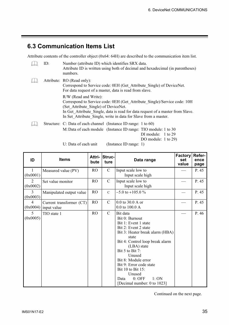
6.3 Communication Items List Attribute contents of the controller object (0x64: 64H) are described to the communication item list.
ID: Number (attribute ID) which identifies SRX data. Attribute ID is written using both of decimal and hexadecimal (in parentheses) numbers.
Attribute: RO (Read only): Correspond to Service code: 0EH (Get_Attribute_Single) of DeviceNet. For data request of a master, data is read from slave. R/W (Read and Write): Correspond to Service code: 0EH (Get_Attribute_Single)/Service code: 10H (Set_Attribute_Single) of DeviceNet. In Get_Attribute_Single, data is read for data request of a master from Slave. In Set_Attribute_Single, write in data for Slave from a master.
Structure: C: Data of each channel (Instance ID range: 1 to 60) M: Data of each module (Instance ID range: TIO module: 1 to 30
DI module: 1 to 29 DO module: 1 to 29)
U: Data of each unit (Instance ID range: 1)
ID Items Attri-bute
Struc-ture Data range
Factory set
value
Refer-ence page
1 (0x0001)
Measured value (PV) RO C Input scale low to Input scale high
⎯ P. 45
2 (0x0002)
Set value monitor
RO C Input scale low to Input scale high
⎯ P. 45
3 (0x0003)
Manipulated output value
RO C −5.0 to +105.0 % ⎯ P. 45
4 (0x0004)
Current transformer (CT) input value
RO C 0.0 to 30.0 A or 0.0 to 100.0 A
⎯ P. 45
5 (0x0005)
TIO state 1 RO C Bit data Bit 0: Burnout Bit 1: Event 1 state Bit 2: Event 2 state Bit 3: Heater break alarm (HBA) state Bit 4: Control loop break alarm (LBA) state Bit 5 to Bit 7: Unused Bit 8: Module error Bit 9: Error code state Bit 10 to Bit 15: Unused Data 0: OFF 1: ON [Decimal number: 0 to 1023]
⎯ P. 46
Continued on the next page.
6. DeviceNet COMMUNICATIONS
36 IMS01N17-E2
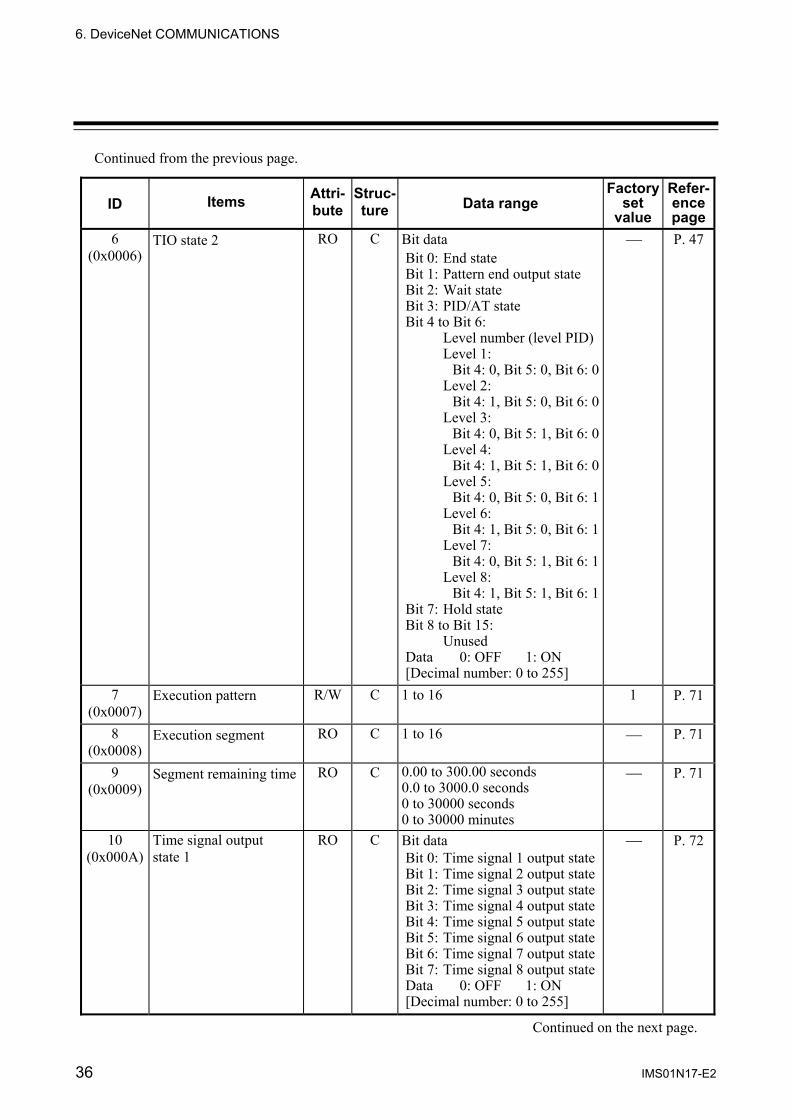
Continued from the previous page.
ID Items Attri-bute
Struc-ture Data range
Factory set
value
Refer-ence page
6 (0x0006)
TIO state 2 RO C Bit data Bit 0: End state Bit 1: Pattern end output state Bit 2: Wait state Bit 3: PID/AT state Bit 4 to Bit 6: Level number (level PID) Level 1: Bit 4: 0, Bit 5: 0, Bit 6: 0 Level 2: Bit 4: 1, Bit 5: 0, Bit 6: 0 Level 3: Bit 4: 0, Bit 5: 1, Bit 6: 0 Level 4: Bit 4: 1, Bit 5: 1, Bit 6: 0 Level 5: Bit 4: 0, Bit 5: 0, Bit 6: 1 Level 6: Bit 4: 1, Bit 5: 0, Bit 6: 1 Level 7: Bit 4: 0, Bit 5: 1, Bit 6: 1 Level 8: Bit 4: 1, Bit 5: 1, Bit 6: 1 Bit 7: Hold state Bit 8 to Bit 15: Unused Data 0: OFF 1: ON [Decimal number: 0 to 255]
⎯ P. 47
7 (0x0007)
Execution pattern R/W C 1 to 16 1 P. 71
8 (0x0008)
Execution segment RO C 1 to 16 ⎯ P. 71
9 (0x0009)
Segment remaining time RO C 0.00 to 300.00 seconds 0.0 to 3000.0 seconds 0 to 30000 seconds 0 to 30000 minutes
⎯ P. 71
10 (0x000A)
Time signal output state 1
RO C Bit data Bit 0: Time signal 1 output state Bit 1: Time signal 2 output state Bit 2: Time signal 3 output state Bit 3: Time signal 4 output state Bit 4: Time signal 5 output state Bit 5: Time signal 6 output state Bit 6: Time signal 7 output state Bit 7: Time signal 8 output state Data 0: OFF 1: ON [Decimal number: 0 to 255]
⎯ P. 72
Continued on the next page.

6. DeviceNet COMMUNICATIONS
IMS01N17-E2 37
Continued from the previous page.
ID Items Attri-bute
Struc-ture Data range
Factory set
value
Refer-ence page
11 (0x000B)
Time signal output state 2
RO C Bit data Bit 0: Time signal 9 output state Bit 1: Time signal 10 output state Bit 2: Time signal 11 output state Bit 3: Time signal 12 output state Bit 4: Time signal 13 output state Bit 5: Time signal 14 output state Bit 6: Time signal 15 output state Bit 7: Time signal 16 output state Data 0: OFF 1: ON [Decimal number: 0 to 255]
⎯ P. 72
12 (0x000C)
Set value (SV) R/W C Input scale low to Input scale high
0 P. 48
13 (0x000D)
Event 1 set value R/W C Deviation high/Deviation low: −Input span to +Input span Deviation high/low, Band:
0 to Input span
0 P. 48
14 (0x000E)
Event 2 set value R/W C Process high/Process low: Input scale low to Input scale high
0 P. 48
15 (0x000F)
Heater break alarm (HBA) set value
R/W C 0.0 to 30.0 A or 0.0 to 100.0 A
0.0 P. 48
16 (0x0010)
Proportional band R/W C TC/RTD input: 0 (0.0) to Input span (Unit: °C [°F]) Voltage (V)/Current (I) input: 0.0 to 1000.0 % of input span
0 (0.0): ON/OFF action
10.0 P. 50
17 (0x0011)
Integral time R/W C 0.1 to 3600.0 seconds 0.01 to 360.00 seconds
40.00 P. 50
18 (0x0012)
Derivative time R/W C 0.0 to 3600.0 seconds 0.00 to 360.00 seconds 0.0 (0.00): Derivative action OFF (PI action)
10.00 P. 50
19 (0x0013)
Operation mode R/W C 0: Unused 1: Monitor 1 2: Monitor 2 3: Control
3 P. 51
20 (0x0014)
PID/AT transfer R/W C 0: PID control operation 1: AT (Autotuning) operation
0 P. 52
21 (0x0015)
Control RUN/STOP transfer
R/W M 0: Control STOP 1: Control RUN
0 P. 53
Continued on the next page.

6. DeviceNet COMMUNICATIONS
38 IMS01N17-E2
Continued from the previous page.
ID Items Attri-bute
Struc-ture Data range
Factory set
value
Refer-ence page
22 (0x0016)
Program operation mode selection
R/W C 0: RESET 1: RUN (Program control) 2: FIX (Fixed set point control) 3: MAN (Manual control)
2 P. 73
23 (0x0017)
Unused ⎯ ⎯ ⎯ ⎯ ⎯
24 (0x0018)
HOLD state R/W C 0: HOLD state OFF 1: HOLD state ON
0 P. 74
25 (0x0019)
STEP action R/W C 0: Not STEP action 1: STEP action execution
0 P. 75
26 (0x001A)
Program operation start mode
R/W C 0: Zero start 1: PV start 1 2: PV start 2
0 P. 76
27 (0x001B)
Control response parameters
R/W C 0: Slow 1: Medium 2: Fast
0 P. 53
28 (0x001C)
PV bias R/W C −Input span to +Input span 0 P. 54
29 (0x001D)
Manual output value R/W C −5.0 to +105.0 % 0.0 P. 54
30 (0x001E)
Output limiter low R/W C −5.0 % to Output limiter high 0.0 P. 54
31 (0x001F)
Output limiter high R/W C Output limiter low to 105.0 % 100.0 P. 54
32 (0x0020)
Proportional cycle time R/W C 0.2 to 50.0 seconds Relay contact output: 20.0 Voltage pulse output: 2.0
P. 55
33 (0x0021)
Digital filter R/W C 0.00 to 10.00 seconds 0.00: OFF (Not provided)
0.00 P. 55
34 (0x0022)
Number of heater break alarm (HBA) delay times
R/W C 1 to 255 times 5 P. 55
35 (0x0023)
Hot/Cold start selection R/W C 0: Hot start 1 1: Hot start 2 2: Cold start 1 3: Cold start 2
0 P. 56
36 (0x0024)
Start determination point R/W C 0 to Input span 0.0 P. 57
37 (0x0025)
Input error determination point (high)
R/W C Input scale low to Input scale high
Input scale high
P. 57
Continued on the next page.

6. DeviceNet COMMUNICATIONS
IMS01N17-E2 39
Continued from the previous page.
ID Items Attri-bute
Struc-ture Data range
Factory set
value
Refer-ence page
38 (0x0026)
Input error determination point (low)
R/W C Input scale low to Input scale high
Input scale low
P. 57
39 (0x0027)
Action at input error (high)
R/W C 0 P. 58
40 (0x0028)
Action at input error (low)
R/W C
0: Normal control 1: Manipulated output value at input error 0 P. 58
41 (0x0029)
Manipulated output value at input error
R/W C −5.0 to +105.0 % 0.0 P. 58
42 (0x002A)
AT differential gap time R/W C 0.00 to 50.00 seconds 0.10 P. 59
43 (0x002B)
AT bias R/W C −Input span to +Input span 0 P. 60
44 (0x002C)
Remote/Local transfer R/W M 0: Local mode 1: Remote mode
0 P. 60
45 (0x002D)
Event LED mode setting R/W M 1: Mode 1 11: Mode 11 2: Mode 2 12: Mode 12 3: Mode 3 13: Mode 13 10: Mode 10 Except the above: Unused
0 (Unused)
P. 61
46 (0x002E)
Digital input setting 1 (RESET)
R/W C 0000 P. 62
47 (0x002F)
Digital input setting 2 (RUN)
R/W C 0000 P. 62
48 (0x0030)
Digital input setting 3 (FIX)
R/W C 0000 P. 62
49 (0x0031)
Digital input setting 4 (MAN)
R/W C 0000 P. 62
50 (0x0032)
Digital input setting 5 (HOLD)
R/W C 0000 P. 63
51 (0x0033)
Digital input setting 6 (STEP)
R/W C 0000 P. 64
52 (0x0034)
Digital input setting 7 (Program pattern selection)
R/W C 0000 P. 65
53 (0x0035)
Digital input setting 8 (AT/PID)
R/W C
0000 to 9999 Upper two digits (Thousands and hundreds digits):
Address of DI module
Lower two digits (Tens and units digits):
Channel number of DI module 00: No function
0000 P. 66
54 (0x0036)
Control loop break alarm (LBA) use selection
R/W C 0: Unused 1: Used
0 P. 67
55 (0x0037)
Control loop break alarm (LBA) time
R/W C 1 to 7200 seconds 80 P. 67
Continued on the next page.
6. DeviceNet COMMUNICATIONS
40 IMS01N17-E2
Continued from the previous page.
ID Items Attri-bute
Struc-ture Data range
Factory set
value
Refer-ence page
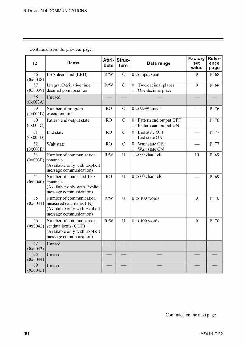
56 (0x0038)
LBA deadband (LBD) R/W C 0 to Input span 0 P. 68
57 (0x0039)
Integral/Derivative time decimal point position
R/W C 0: Two decimal places 1: One decimal place
0 P. 69
58 (0x003A)
Unused ⎯ ⎯ ⎯ ⎯ ⎯
59 (0x003B)
Number of program execution times
RO C 0 to 9999 times ⎯ P. 76
60 (0x003C)
Pattern end output state RO C 0: Pattern end output OFF 1: Pattern end output ON
⎯ P. 76
61 (0x003D)
End state RO C 0: End state OFF 1: End state ON
⎯ P. 77
62 (0x003E)
Wait state RO C 0: Wait state OFF 1: Wait state ON
⎯ P. 77
63 (0x003F)
Number of communication channels (Available only with Explicit message communication)
R/W U 1 to 60 channels 10 P. 69
64 (0x0040)
Number of connected TIO channels (Available only with Explicit message communication)
RO U 0 to 60 channels ⎯ P. 69
65 (0x0041)
Number of communication measured data items (IN) (Available only with Explicit message communication)
R/W U 0 to 100 words 0 P. 70
66 (0x0042)
Number of communication set data items (OUT) (Available only with Explicit message communication)
R/W U 0 to 100 words 0 P. 70
67 (0x0043)
Unused ⎯ ⎯ ⎯ ⎯ ⎯
68 (0x0044)
Unused ⎯ ⎯ ⎯ ⎯ ⎯
69 (0x0045)
Unused ⎯ ⎯ ⎯ ⎯ ⎯
Continued on the next page.

6. DeviceNet COMMUNICATIONS
IMS01N17-E2 41
Continued from the previous page.
ID Items Attri-bute
Struc-ture Data range
Factory set
value
Refer-ence page
70 (0x0046)
Input state of digital input (terminal) (DI module)
RO M Bit data Bit 0: DI channel 1 Bit 1: DI channel 2 Bit 2: DI channel 3 Bit 3: DI channel 4 Bit 4: DI channel 5 Bit 5: DI channel 6 Bit 6: DI channel 7 Bit 7: DI channel 8 Bit 8: DI channel 9 Bit 9: DI channel 10 Bit 10: DI channel 11 Bit 11: DI channel 12 Bit 12 to Bit 15: Unused Data 0: OFF 1: ON [Decimal number: 0 to 4095]
⎯ P. 78
71 (0x0047)
Input state of digital input (connector) 1 (DI module)
RO M Bit data Bit 0: DI channel 13 Bit 1: DI channel 14 Bit 2: DI channel 15 Bit 3: DI channel 16 Bit 4: DI channel 17 Bit 5: DI channel 18 Bit 6: DI channel 19 Bit 7: DI channel 20 Bit 8 to Bit 15: Unused Data 0: OFF 1: ON [Decimal number: 0 to 255]
⎯ P. 79
72 (0x0048)
Input state of digital input (connector) 2 (DI module)
RO M Bit data Bit 0: DI channel 21 Bit 1: DI channel 22 Bit 2: DI channel 23 Bit 3: DI channel 24 Bit 4: DI channel 25 Bit 5: DI channel 26 Bit 6: DI channel 27 Bit 7: DI channel 28 Bit 8 to Bit 15: Unused Data 0: OFF 1: ON [Decimal number: 0 to 255]
⎯ P. 79
73 (0x0049)
Error code (DI module)
RO M Bit data Bit 0: Backup error Bit 1 to Bit 15: Unused Data 0: OFF 1: ON [Decimal number: 0 to 1]
⎯ P. 80
Continued on the next page.

6. DeviceNet COMMUNICATIONS
42 IMS01N17-E2
Continued from the previous page.
ID Items Attri-bute
Struc-ture Data range
Factory set
value
Refer-ence page
74 (0x004A)
Output state of digital output (terminal) (DO module)
RO M Bit data Bit 0: DO channel 1 Bit 1: DO channel 2 Bit 2: DO channel 3 Bit 3: DO channel 4 Bit 4: DO channel 5 Bit 5: DO channel 6 Bit 6: DO channel 7 Bit 7: DO channel 8 Bit 8: DO channel 9 Bit 9: DO channel 10 Bit 10: DO channel 11 Bit 11: DO channel 12 Bit 12 to Bit 15: Unused Data 0: OFF 1: ON [Decimal number: 0 to 4095]
⎯ P. 81
75 (0x004B)
Output state of digital output (connector) 1 (DO module)
RO M Bit data Bit 0: DO channel 13 Bit 1: DO channel 14 Bit 2: DO channel 15 Bit 3: DO channel 16 Bit 4: DO channel 17 Bit 5: DO channel 18 Bit 6: DO channel 19 Bit 7: DO channel 20 Bit 8 to Bit 15: Unused Data 0: OFF 1: ON [Decimal number: 0 to 255]
⎯ P. 82
76 (0x004C)
Output state of digital output (connector) 2 (DO module)
RO M Bit data Bit 0: DO channel 21 Bit 1: DO channel 22 Bit 2: DO channel 23 Bit 3: DO channel 24 Bit 4: DO channel 25 Bit 5: DO channel 26 Bit 6: DO channel 27 Bit 7: DO channel 28 Bit 8 to Bit 15: Unused Data 0: OFF 1: ON [Decimal number: 0 to 255]
⎯ P. 82
Continued on the next page.
6. DEVICENET COMMUNICATIONS
IMS01N17-E2 43
Continued from the previous page.
ID Items Attri-bute
Struc-ture Data range
Factory set
value
Refer-ence page
77 (0x004D)
Manual output setting of digital output (terminal) (DO module)
R/W M Bit data Bit 0: DO channel 1 Bit 1: DO channel 2 Bit 2: DO channel 3 Bit 3: DO channel 4 Bit 4: DO channel 5 Bit 5: DO channel 6 Bit 6: DO channel 7 Bit 7: DO channel 8 Bit 8: DO channel 9 Bit 9: DO channel 10 Bit 10: DO channel 11 Bit 11: DO channel 12 Bit 12 to Bit 15: Unused Data 0: OFF 1: ON [Decimal number: 0 to 4095]
Bit 0 to Bit 15: 0 [Decimal number: 0]
P. 83
78 (0x004E)
Manual output setting 1 of digital output (connector) (DO module)
R/W M Bit data Bit 0: DO channel 13 Bit 1: DO channel 14 Bit 2: DO channel 15 Bit 3: DO channel 16 Bit 4: DO channel 17 Bit 5: DO channel 18 Bit 6: DO channel 19 Bit 7: DO channel 20 Bit 8 to Bit 15: Unused Data 0: OFF 1: ON [Decimal number: 0 to 255]
Bit 0 to Bit 15: 0 [Decimal number: 0]
P. 84
79 (0x004F)
Manual output setting 2 of digital output (connector) (DO module)
R/W M Bit data Bit 0: DO channel 21 Bit 1: DO channel 22 Bit 2: DO channel 23 Bit 3: DO channel 24 Bit 4: DO channel 25 Bit 5: DO channel 26 Bit 6: DO channel 27 Bit 7: DO channel 28 Bit 8 to Bit 15: Unused Data 0: OFF 1: ON [Decimal number: 0 to 255]
Bit 0 to Bit 15: 0 [Decimal number: 0]
P. 84
80 (0x0050)
Error code (DO module)
RO M Bit data Bit 0: Backup error Bit 1 to Bit 15: Unused Data 0: OFF 1: ON [Decimal number: 0 to 1]
⎯ P. 85

44 IMS01N17-E2
7. COMMUNICATION DATA DESCRIPTION Referance to communication data contents
(1) Name: Communication data name is written.
(2) Attribute ID: Arrtribute ID of controller object (0x64: 64H) is written. These Arrtribute ID are written using both of hexadecimal and decimal (in perantheses) numbers.
(3) Description: A short description of the communication data item is written.
(4) Attribute: A method of how communication data items are read or written when viewed from the master (PLC) is described.
RO: Only reading data is possible.
R/W: Reading and writing data is possible.
(5) Number of data: The number of maximum communication data points is written.
Communication data of each channel: 60 (Instance ID range: 1 to 60) Communication data of each module: • TIO module: 30 (Instance ID range: 1 to 30) • DI/DO module: 29 (Instance ID range: 1 to 29) Communication data of each unit: 1 (Instance ID range: 1)
(6) Data range: The reading range or the writing range of communication data is written.
(7) Related parameters: A name and a page of relational items are written.
(8) Factory set value: The factory set value of communication data is written.
There is item including the functional description.
Manual output value Attribute ID 29 (0x001D)
Use to set the output value in the manual control.
Attribute: R/W (Read and Write)
Number of data: 60 (Data of each channel)
Data range: −5.0 to +105.0 % (However, the actual output value is within output limiter range.)
Related parameters: Output limiter high/low (P. 54), Program operation mode selection (P. 73)
Factory set value: 0.0
(1) (2)
(3)
(4)
(5)
(6)
(7)
(8)
Slave (SRX) Master (PLC)Data direction
Slave (SRX) Master (PLC)Data direction
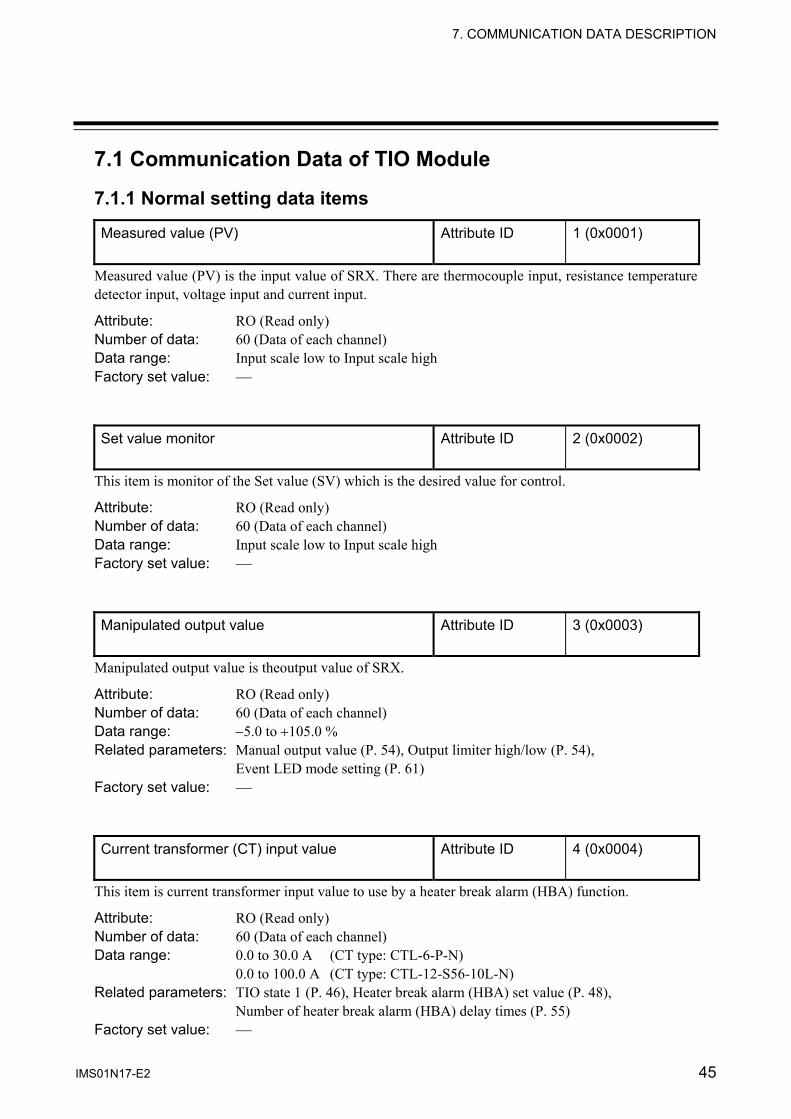
7. COMMUNICATION DATA DESCRIPTION
IMS01N17-E2 45
7.1 Communication Data of TIO Module
7.1.1 Normal setting data items
Measured value (PV) Attribute ID 1 (0x0001)
Measured value (PV) is the input value of SRX. There are thermocouple input, resistance temperature detector input, voltage input and current input.
Attribute: RO (Read only) Number of data: 60 (Data of each channel) Data range: Input scale low to Input scale high Factory set value: ⎯ Set value monitor Attribute ID 2 (0x0002)
This item is monitor of the Set value (SV) which is the desired value for control.
Attribute: RO (Read only) Number of data: 60 (Data of each channel) Data range: Input scale low to Input scale high Factory set value: ⎯ Manipulated output value Attribute ID 3 (0x0003)
Manipulated output value is theoutput value of SRX.
Attribute: RO (Read only) Number of data: 60 (Data of each channel) Data range: −5.0 to +105.0 % Related parameters: Manual output value (P. 54), Output limiter high/low (P. 54),
Event LED mode setting (P. 61) Factory set value: ⎯ Current transformer (CT) input value Attribute ID 4 (0x0004)
This item is current transformer input value to use by a heater break alarm (HBA) function.
Attribute: RO (Read only) Number of data: 60 (Data of each channel) Data range: 0.0 to 30.0 A (CT type: CTL-6-P-N)
0.0 to 100.0 A (CT type: CTL-12-S56-10L-N) Related parameters: TIO state 1 (P. 46), Heater break alarm (HBA) set value (P. 48),
Number of heater break alarm (HBA) delay times (P. 55) Factory set value: ⎯

7. COMMUNICATION DATA DESCRIPTION
46 IMS01N17-E2
TIO state 1 Attribute ID 5 (0x0005)
Each event state such as burnout, event 1, event 2, heater break alarm (HBA), control loop break alarm (LBA), module error or error code is expressed in bit data items.
Attribute: RO (Read only) Number of data: 60 (Data of each channel) Data range: 0 to 1023 (bit data)
Each event state is assigned as a bit image in binary numbers.
Bit image: 0000000000000000
Bit 15・・・・・・・・・・・・・・・・ Bit 0
Bit data: 0: OFF 1: ON
Bit 0: Burnout Become ON in input break.
Bit 1, Bit 2: Event 1 state, Event 2 state Event type: Deviation high, Deviation low, Deviation high/low, Band, Process high, Process low Can change an event type by host communication.
Bit 3: Heater break alarm (HBA) state This is valid only when heater break alarm (HBA) function is used. However, heater break alarm function cannot be used when control output is Voltage/Current output.
Bit 4: Control loop break alarm (LBA) state This is valid only when control loop break alarm (LBA) function is used. The Use/Unused of the control loop break alarm (LBA) is selected and control loop break alarm (LBA) related settings are made via host communication.
Bit 5 to Bit 7: Unused Bit 8: Module error
To be turned on when no communication with the relevant module (channel) can be conducted (no response).
Bit 9: Error code To be turned on when the value becomes more than 1 as any error occurs in the host communication error code.
Bit 10 to Bit 15: Unused For host communication, refer to the Module Type Controller SRX Communication Instruction Manual (IMS01N01-E ).
Related parameters: Event set value (P. 48), Heater break alarm (HBA) set value (P. 48), Number
of heater break alarm (HBA) delay times (P. 55), Control loop break alarm (LBA) use selection (P. 67), Control loop break alarm (LBA) time (P. 67), LBA deadband (LBD) (P. 68)
Factory set value: ⎯

7. COMMUNICATION DATA DESCRIPTION
IMS01N17-E2 47
TIO state 2 Attribute ID 6 (0x0006)
End state, pattern end output state, wait state, PID/AT state, level number or hold state is expressed in bit data items.
Attribute: RO (Read only) Number of data: 60 (Data of each channel) Data range: 0 to 255 (bit data)
Each event state is assigned as a bit image in binary numbers.
Bit image: 0000000000000000
Bit 15・・・・・・・・・・・・・・・・ Bit 0
Bit data: 0: OFF 1: ON
Bit 0: End state The state at the end of program operation is monitored. It is turned on at the end of program operation. The state of being turned on is kept until the program is executed again.
Bit 1: Pattern end output state The pattern end output state output at the end of program operation is monitored. It is turned on at the end of program operation. Time to be turned on can be set by setting the pattern end output time.
Bit 2: Wait state Program operation is turned on in the wait state.
Bit 3: PID/AT state Monitor a control state. Set to 0 during PID control or 1 during autotuning (AT) execution.
Bit 4 to Bit 6: Level number (level PID) The level PID function enables monitoring the present Set value (SV) level. The bit ON/OFF status now set represents the corresponding level number (from 1 to 8).
Level 1 2 3 4 5 6 7 8 Bit 4 0 1 0 1 0 1 0 1 Bit 5 0 0 1 1 0 0 1 1 Bit 6 0 0 0 0 1 1 1 1
Bit 7: Hold state
The hold state of program operation is monitored. Turned on when program operation is in the temporary stop state (hold state).
Bit 8 to Bit 15: Unused Related parameters: Hold state (P. 74), Pattern end output state (P. 76), End state (P. 77),
Wait state (P. 77) Factory set value: ⎯

7. COMMUNICATION DATA DESCRIPTION
48 IMS01N17-E2
Set value (SV) Attribute ID 12 (0x000C)
Set value (SV) is desired value of the control. Attribute: R/W (Read and Write) Number of data: 60 (Data of each channel) Data range: Input scale low to Input scale high Factory set value: 0 Event 1 set value Attribute ID 13 (0x000D)
Event 2 set value Attribute ID 14 (0x000E)
This item is setting value of an event action. Attribute: R/W (Read and Write) Number of data: 60 (Data of each channel) Data range: Deviation high/Deviation low: −Input span to +Input span
Deviation high/low, Band: 0 to Input span Process high/Process low: Input scale low limit to Input scale high limit (Input span: Input scale low limit to Input scale high limit)
Related parameters: TIO state 1 (P. 46) Factory set value: 0
An event type sets with a host communication. For host communication, refer to the Module Type Controller SRX Communication Instruction Manual (IMS01N01-E ).
Heater break alarm (HBA) set value Attribute ID 15 (0x000F)
This item is setting value of heater break alarm (HBA). HBA set value is set by referring to current transformer (CT) input value. Attribute: R/W (Read and Write) Number of data: 60 (Data of each channel) Data range: 0.0 to 30.0 A (CT type: CTL-6-P-N)
0.0 to 100.0 A (CT type: CTL-12-S56-10L-N) Set HBA set value to a value about 85 % of current transformer (CT) input value. However, when power supply variations are large, set the HBA set value to a slightly smaller value. In addition, when two or more heaters are connected in parallel, set the HBA set value to a slightly larger value so that it is activated even with only one heater is broken (However, within the CT input value).
Related parameters: Current transformer (CT) input value (P. 45), Number of heater break alarm (HBA) delay times (P. 55)
Factory set value: 0.0 Heater break alarm function cannot be used when control output is Voltage/Current output.
Continued on the next page.

7. COMMUNICATION DATA DESCRIPTION
IMS01N17-E2 49
Continued from the previous page. Function: The heater break alarm (HBA) function detects a fault in the heating or cooling
circuit and displays actual amperage on the display by monitoring the current draw of the load by the current transformer (CT).
• When no heater current flows: Heater break or faulty operating unit, etc.
When the control output is on and the CT input value is equal to or less than the HBA set value, an alarm status is produced. However, heater break alarm does not action when control output ON time is 0.1 second or less.
Control output OFF OFFON ON
OFF Alarm output ON
Capture
Capture
Capture
Capture
HBA set value
CT input value
• When the heater current cannot be turned off: Welded realy contact, etc. When the control output is off and the CT input value is equal to greater than the HBA set value, an alarm status is produced. However, heater break alarm does not action when control output OFF time is 0.1 second or less.
OFF Alarm output ON
HBA set value
Capture
Capture
Capture
CT input value
Control output OFF ON OFF ON

7. COMMUNICATION DATA DESCRIPTION
50 IMS01N17-E2
Proportional band Attribute ID 16 (0x0010)
Use to set the proportional band of the PI and PID control.
Attribute: R/W (Read and Write) Number of data: 60 (Data of each channel) Data range: TC/RTD input: 0 (0.0) to Input span (Unit: °C [°F])
Voltage (V)/Current (I) input: 0.0 to 1000.0 % of input span 0 (0.0): ON/OFF action (Input span: Input scale low to Input scale high)
Factory set value: 10.0 Integral time Attribute ID 17 (0x0011)
Integral action is to eliminate offset between Set value (SV) and Measured value (PV) by proportional action.
Attribute: R/W (Read and Write) Number of data: 60 (Data of each channel) Data range: 0.01 to 360.00 seconds
0.1 to 3600.0 seconds A decimal point position selects with an Integral/Derivative time decimal point position (P. 69).
Factory set value: 40.00 Derivative time Attribute ID 18 (0x0012)
Derivative action is to prevent rippling and make control stable by monitoring output change.
Attribute: R/W (Read and Write) Number of data: 60 (Data of each channel) Data range: 0.00 to 360.00 seconds
0.0 to 3600.0 seconds 0.0 (0.00): Derivative action OFF (PI action) A decimal point position selects with an Integral/Derivative time decimal point position (P. 69).
Factory set value: 10.00

7. COMMUNICATION DATA DESCRIPTION
IMS01N17-E2 51
Operation mode Attribute ID 19 (0x0013)
This item selects Unused, Monitor or Control for each channel. Attribute: R/W (Read and Write) Number of data: 60 (Data of each channel) Data range: 0: Unused: Execute neither monitor nor the control
1: Monitor 1: Execute only data monitor 2: Monitor 2: Execute data monitor and an event action (include HBA and LBA) 3: Control: Execute the control
Related parameters: Event LED mode setting (P. 61), Program operation mode selection (P. 73) Factory set value: 3: Control
Relationship between operation mode and program operation mode • The program operation mode becomes “0: RESET (Reset mode)” when the operation
mode is set to “0: Unused.” • It the operation mode is set to any mode other than “0: Unused” with the program
operation mode set to “0: RESET (Reset mode)” or “2: FIX (fixed set point control),” it is set to the latter.
• The program operation mode becomes “1: Monitor 1” when the operation mode is set to “0: RESET (Reset mode).”
• The program operation mode becomes “3: Control” when the operation mode is set to any mode other than “0: RESET (Reset mode).”
Mode state Item Operation 1 Operation
mode Program operation
mode Other than“Unused” → Unused Unused RESET
Operation mode Any mode →
Other than “Unused”
Other than “Unused” FIX 2
Other than“RESET” → RESET Monitor 1 RESET Program
operation mode Any mode →Other than “RESET” Control Other than “RESET”
1 If must be set to the different mode before or after operation. 2 This is valid only when the program run mode before operation is set to RESET or FIX.
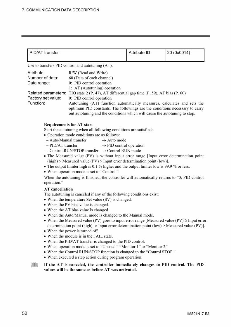
7. COMMUNICATION DATA DESCRIPTION
52 IMS01N17-E2
PID/AT transfer Attribute ID 20 (0x0014)
Use to transfers PID control and autotuning (AT).
Attribute: R/W (Read and Write) Number of data: 60 (Data of each channel) Data range: 0: PID control operation
1: AT (Autotuning) operation Related parameters: TIO state 2 (P. 47), AT differential gap time (P. 59), AT bias (P. 60) Factory set value: 0: PID control operation Function: Autotuning (AT) function automatically measures, calculates and sets the
optimum PID constants. The followings are the conditions necessary to carry out autotuning and the conditions which will cause the autotuning to stop.
Requirements for AT start Start the autotuning when all following conditions are satisfied: • Operation mode conditions are as follows:
− Auto/Manual transfer → Auto mode − PID/AT transfer → PID control operation − Control RUN/STOP transfer → Control RUN mode
• The Measured value (PV) is without input error range [Input error determination point (high) > Measured value (PV) > Input error determination point (low)].
• The output limiter high is 0.1 % higher and the output limiter low is 99.9 % or less. • When operation mode is set to “Control.” When the autotuning is finished, the controller will automatically returns to “0: PID control operation.”
AT cancellation The autotuning is canceled if any of the following conditions exist: • When the temperature Set value (SV) is changed. • When the PV bias value is changed. • When the AT bias value is changed. • When the Auto/Manual mode is changed to the Manual mode. • When the Measured value (PV) goes to input error range [Measured value (PV) ≥ Input error
determination point (high) or Input error determination point (low) ≥ Measured value (PV)]. • When the power is turned off. • When the module is in the FAIL state. • When the PID/AT transfer is changed to the PID control. • When operation mode is set to “Unused,” “Monitor 1” or “Monitor 2.” • When the Control RUN/STOP function is changed to the “Control STOP.” • When executed a step action during program operation.
If the AT is canceled, the controller immediately changes to PID control. The PID values will be the same as before AT was activated.
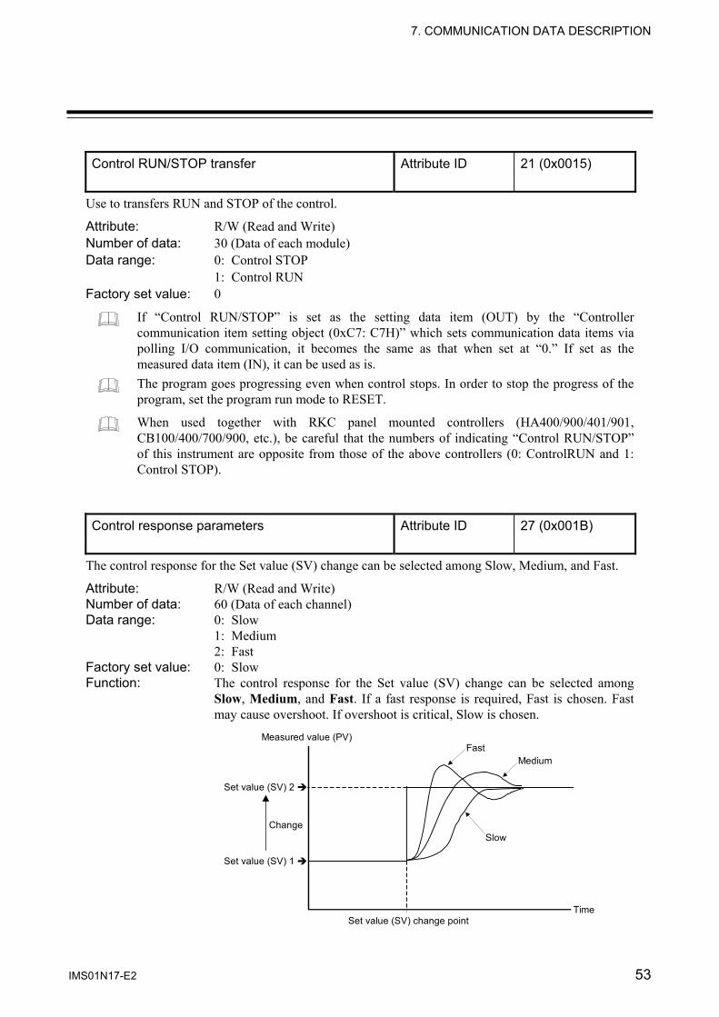
7. COMMUNICATION DATA DESCRIPTION
IMS01N17-E2 53
Control RUN/STOP transfer Attribute ID 21 (0x0015)
Use to transfers RUN and STOP of the control.
Attribute: R/W (Read and Write) Number of data: 30 (Data of each module) Data range: 0: Control STOP
1: Control RUN Factory set value: 0
If “Control RUN/STOP” is set as the setting data item (OUT) by the “Controller communication item setting object (0xC7: C7H)” which sets communication data items via polling I/O communication, it becomes the same as that when set at “0.” If set as the measured data item (IN), it can be used as is. The program goes progressing even when control stops. In order to stop the progress of the program, set the program run mode to RESET.
When used together with RKC panel mounted controllers (HA400/900/401/901, CB100/400/700/900, etc.), be careful that the numbers of indicating “Control RUN/STOP” of this instrument are opposite from those of the above controllers (0: ControlRUN and 1: Control STOP).
Control response parameters Attribute ID 27 (0x001B)
The control response for the Set value (SV) change can be selected among Slow, Medium, and Fast.
Attribute: R/W (Read and Write) Number of data: 60 (Data of each channel) Data range: 0: Slow
1: Medium 2: Fast
Factory set value: 0: Slow Function: The control response for the Set value (SV) change can be selected among
Slow, Medium, and Fast. If a fast response is required, Fast is chosen. Fast may cause overshoot. If overshoot is critical, Slow is chosen.
Measured value (PV)
Change
Set value (SV) change pointTime
FastMedium
Slow
Set value (SV) 1
Set value (SV) 2

7. COMMUNICATION DATA DESCRIPTION
54 IMS01N17-E2
PV bias Attribute ID 28 (0x001C)
PV bias adds bias to the Measured value (PV). The PV bias is used to compensate the individual variations of the sensors or correct the difference between the Measured value (PV) of other instruments.
Attribute: R/W (Read and Write) Number of data: 60 (Data of each channel) Data range: −Input span to +Input span
(Input span: Input scale low to Input scale high) Factory set value: 0 Manual output value Attribute ID 29 (0x001D)
Use to set the output value in the manual control.
Attribute: R/W (Read and Write) Number of data: 60 (Data of each channel) Data range: −5.0 to +105.0 %
(However, the actual output value is within output limiter range.) Related parameters: Output limiter high/low (P. 54), Program operation mode selection (P. 73) Factory set value: 0.0 Output limiter low Attribute ID 30 (0x001E)
Output limiter high Attribute ID 31 (0x001F)
Use to set the high limit value (or low limit value) of manipulated output.
Attribute: R/W (Read and Write) Number of data: 60 (Data of each channel) Data range: Output limiter low: −5.0 % to Output limiter high
Output limiter high: Output limiter low to 105.0 % Related parameters: Manipulated output value (P. 45) Factory set value: Output limiter low: 0.0
Output limiter high: 100.0

7. COMMUNICATION DATA DESCRIPTION
IMS01N17-E2 55
Proportional cycle time Attribute ID 32 (0x0020)
Proportional cycle time is to set control cycle time for time based control output such as voltage pulse output and relay contact output.
Attribute: R/W (Read and Write) Number of data: 60 (Data of each channel) Data range: 0.2 to 50.0 seconds Factory set value: Relay contact output: 20.0
Voltage pulse output: 2.0 The proportional cycle time becomes invalid when the Voltage/Current output is selected as control output type
Digital filter Attribute ID 33 (0x0021)
This item is the time of the first-order lag to eliminate noise against the measured input. Attribute: R/W (Read and Write) Number of data: 60 (Data of each channel) Data range: 0.00 to 10.00 seconds
0.00: Digital filter OFF Factory set value: 0.00 Number of heater break alarm (HBA) delay times Attribute ID 34 (0x0022)
It the number of heater break alarm (HBA) times continues its preset times (the number of sampling times), the heater break alarm is turned on.
Attribute: R/W (Read and Write) Number of data: 60 (Data of each channel) Data range: 1 to 255 times Related parameters: Current transformer (CT) input value (P. 45),
Heater break alarm (HBA) set value (P.48) Factory set value: 5 Function: Heater break alarm (HBA) delay time = Number of delay times × Sampling time
(Sampling time: 500 ms) [Example] Number of delay times: 5 times (factory set value) HBA delay time = 5 times × 500 ms = 2500 ms = 2.5 seconds
HBA state ON
OFF
HBA ON state
HBA ON
HBA delay time

7. COMMUNICATION DATA DESCRIPTION
56 IMS01N17-E2
Hot/Cold start selection Attribute ID 35 (0x0023)
The start mode is selected when the power failure recovers; control is started; the operation mode is set to Control; or the program operation mode is set to RUN or FIX from RESET.
Attribute: R/W (Read and Write) Number of data: 60 (Data of each channel) Data range: 0: Hot start 1
1: Hot start 2 2: Cold start 1 3: Cold start 2
Related parameters: Operation mode (P. 51), Control RUN/STOP transfer (P. 53), Start determination point (P. 57), Program operation mode selection (P. 73)
Factory set value: 0 Function: Hot/Cold start state
Control RUN/STOP Operation mode Program
operation mode
Power recovery STOP → RUN
Other than Control
→ Control RESET → RUN FIX
Hot start 1 Same as that before power failure
Same as that before STOP
Same as that before Other than Control
Hot start 2 Value as a result of control computation 1, 2, 3
Value as a result of control computation 2, 3
Value as a result of control computation 2, 3
Low limit value of output
Cold start 1 Low limit value of output 3 (Change to MAN mode)
Low limit value of output 3 (Change to MAN mode)
Low limit value of output 3 (Change to MAN mode)
Low limit value of output (Change to MAN mode)
Cold start 2 Low limit value of output (Change to RESET mode 4)
Same as that before STOP
Same as that before Other than Control
Low limit value of output
1 Same as that before power failure when mode is MAN mode. 2 The result of control computation varies with the control designation parameter. 3 The value becomes the same output as in Hot start 1 when Measured value (PV) is within the range of the
start determination point. 4 RESET mode: Control: STOP
Segment: Return to segment No.1 Time signal output: OFF End output: OFF Event: OFF Set value (SV): 0

7. COMMUNICATION DATA DESCRIPTION
IMS01N17-E2 57
Start determination point Attribute ID 36 (0x0024)
This item is the determination point of the hot start. Setting is deviation setting with temperature setting value.
Attribute: R/W (Read and Write) Number of data: 60 (Data of each channel) Data range: 0 to Input span (Input span: Input scale low limit to Input scale high limit) Related parameters: Hot/Cold start selection (P. 56) Factory set value: 0 Function: • The start state is determined according to the Measured value (PV) level
(deviation from set value) at power recovery. • When the Measured value (PV) is between the + (plus) and − (minus) side
determination points, start power recovery always becomes “Hot start 1.” (However, except “Cold start 2”)
• When the Measured value (PV) is outside the determination points, operation starts in the start status selected by Hot/Cold start selection.
Minus side start determination point Plus side start determination point
Hot or Cold start Hot start 1 Hot or Cold start
Low ▲ △ High Set value (SV) Start determination point setting
Input error determination point (high) Attribute ID 37 (0x0025)
Input error determination point (low) Attribute ID 38 (0x0026)
Use to set input error determination point (high or low). Input error determination function is activated when the input measured value reaches the limit, and control output value selected by action at input error will be output.
Attribute: R/W (Read and Write) Number of data: 60 (Data of each channel) Data range: Input scale low to Input scale high Related parameters: Action at input error (high/low) (P. 58),
Manipulated output value at input error (P. 58) Factory set value: Input error determination point (high): Input scale high
Input error determination point (low): Input scale low

7. COMMUNICATION DATA DESCRIPTION
58 IMS01N17-E2
Action at input error (high) Attribute ID 39 (0x0027)
Action at input error (low) Attribute ID 40 (0x0028)
Use to selects the action when the input measured value reaches the input error determination point (high or low). Attribute: R/W (Read and Write) Number of data: 60 (Data of each channel) Data range: 0: Normal control (The present output)
1: Manipulated output value at input error Related parameters: Input error determination point (high/low) (P. 57),
Manipulated output value at input error (P. 58) Factory set value: 0: Normal control (The present output) Function: An example of the following explains input error determination point and
action at input error. [Example] Input range: 0 to 400 °C
Input error determination point (high): 300 °C Input error determination point (low): 50 °C
Action area at input error
Differential gap (0.1 % of input span)
Input error determination point (high)
Input range
0 °C 50 °C 300 °C
Manipulated output value at input error
400 °C
Select one of these
(Within input scale range)
Input error determinationpoint (low)
Manipulated output value at input error
Manipulated output value (MV) obtained by PID control
PID control output
Action area at input error
Select one of these
PID control output Manipulated output value at input error Attribute ID 41 (0x0029)
When the input measured value reaches input error determination point and action at input error is set to “1,” this manipulated value is output. Attribute: R/W (Read and Write) Number of data: 60 (Data of each channel) Data range: −5.0 to +105.0 %
(However, the actual output value is within output limiter range.) Related parameters: Input error determination point (high/low) (P. 57),
Action at input error (high/low) (P. 58) Factory set value: 0.0

7. COMMUNICATION DATA DESCRIPTION
IMS01N17-E2 59
AT differential gap time Attribute ID 42 (0x002A)
Use to set an ON/OFF action differential gap time for autotuning. This function prevents the AT function from malfunctioning caused by noise.
Attribute: R/W (Read and Write) Number of data: 60 (Data of each channel) Data range: 0.00 to 50.00 seconds Related parameters: PID/AT transfer (P. 52) Factory set value: 0.10 Function: In order to prevent the output from chattering due to the fluctuation of a
Measured value (PV) caused by noise during autotuning, the output on or off state is held until “AT differential gap time” has passed after the output on/off state is changed to the other. Set “AT differential gap time” to ”1/100 × Time required for temperature rise.”
[Example] A: AT cycle time when the AT differential gap time is set to 0.00 second
The output chatters due to the fluctuation of the Measured value (PV) caused by noise, and autotuning function is not able to monitor appropriate cycles to calculate suitable PID values.
B: AT cycle time when the AT differential gap time is set to “Time corresponding to 0.25 cycles” The fluctuation of a Measured value (PV) caused by noise is ignored and as a result autotuning function is able to monitor appropriate cycles to calculate suitable PID values.
The AT cycle of SRX is 2 cycles.
Measured value (PV)
Set value (SV)
Time AT start
A Fluctuation of Measured value (PV) caused by noise
AT differential gap time
B

7. COMMUNICATION DATA DESCRIPTION
60 IMS01N17-E2
AT bias Attribute ID 43 (0x002B)
Use to set a bias to move the set value only when autotuning is activated. Attribute: R/W (Read and Write) Number of data: 60 (Data of each channel) Data range: −Input span to +Input span
(Input span: Input scale low to Input scale high) Related parameters: PID/AT transfer (P. 52) Factory set value: 0 Function: The AT bias is used to prevent overshoot during autotuning in the application
which does not allow overshoot even during autotuning. RKC autotuning method uses ON/OFF control at the set value to calculate the PID values. However, if overshoot is a concern during autotuning, the desired AT bias should be set to lower the set point during autotuning so that overshoot is prevented.
• When AT bias is set to the minus (−) side Remote/Local transfer Attribute ID 44 (0x002C)
Use to transfers the remote mode and the local mode. For the remote mode, the input of channel 2 (the remote input) becomes Set value (SV) of channel 1. Attribute: R/W (Read and Write) Number of data: 30 (Data of each module) Data range: 0: Local mode
1: Remote mode Factory set value: 0: Local mode
For the remote mode, the input of channel 2 corresponds to a scale of channel 1. [Example] Channel 1 input scale range: 0 to 400 °C
Channel 2 input (remote input): 0 to 10 V • Channel 2 input: 10 V → Channel 1 set value: 400 °C • Channel 2 input: 5 V → Channel 1 set value: 200 °C
Measured value (PV)
Set value (SV)
AT point AT bias
Time

7. COMMUNICATION DATA DESCRIPTION
IMS01N17-E2 61
Event LED mode setting Attribute ID 45 (0x002D)
This item is for selecting the indicating details of 4 EVENT lamps located at the front of the module. Attribute: R/W (Read and Write) Number of data: 30 (Data of each module) Data range: 0: Unused (No display)
1: Mode 1 2: Mode 2 3: Mode 3 10: Mode 10 11: Mode 11 12: Mode 12 13: Mode 13 Except the above: Unused
Factory set value: 0 (No display) Function: Relationship between the content of each mode and each EVENT lamp
Mode EVENT 1 lamp EVENT 2 lamp EVENT 3 lamp EVENT 4 lamp 1 ch1 Event 1 ch1 Event 2 ch2 Event 1 ch2 Event 2 2 ch1 Comprehensive
event 1 ch2 Comprehensive event 1
ch1 Output status 2 ch2 Output status 2
3 ch1 Comprehensive event 1
ch2 Comprehensive event 1
ch1 Control status 3 ch2 Control status 3
10 ch1 Execution segment (Sixteen segments are expressed in combination of these lamps.) 4
11 ch2 Execution segment (Sixteen segments are expressed in combination of these lamps.) 4
12 ch1 Time signal 1 ch1 Time signal 2 ch1 Time signal 3 ch1 Time signal 413 ch2 Time signal 1 ch2 Time signal 2 ch2 Time signal 3 ch2 Time signal 4
1 If any one of burnout, event 1, event 2, heater break alarm and control loop break
alarm is turned on, the comprehensive event is turned on (lit). 2 For Voltage output/Current output, it is always turned off (extinguished). 3 When “Control RUN/STOP” is set to “Control RUN” and the operation mode is set
to “Control,” it is turned on (lit). 4 Relationship between EVENT lamp lighting state and segment number
Segment No. 1 2 3 4 5 6 7 8 9 10 11 12 13 14 15 16
EVENT 1 lamp − × − × − × − × − × − × − × − ×
EVENT 2 lamp − − × × − − × × − − × × − − × ×
EVENT 3 lamp − − − − × × × × − − − − × × × ×
EVENT 4 lamp − − − − − − − − × × × × × × × ×
×: ON −: OFF

7. COMMUNICATION DATA DESCRIPTION
62 IMS01N17-E2
Digital input setting 1 (RESET) Attribute ID 46 (0x002E)
Digital input setting 2 (RUN) Attribute ID 47 (0x002F)
Digital input setting 3 (FIX) Attribute ID 48 (0x0030)
Digital input setting 4 (MAN) Attribute ID 49 (0x0031)
To contact of DI module, assigned to the input of program operation mode transfer. Attribute: R/W (Read and Write) Number of data: 60 (Data of each channel) Data range: 0000 to 9999
Upper two digits (Thousands and hundreds digits): Address of DI module Lower two digits (Tens and units digits): Channel number of DI module
Related parameters: Program operation mode selection (P. 73) Factory set value: 0000 (No function) Function: • When the contact corresponding to the channel set by “Digital input setting
1” is closed from the open condition (rising edge), the program operation mode is set to the RESET mode.
• When the contact corresponding to the channel set by “Digital input setting 2” is closed from the open condition (rising edge), the program operation mode is set to the program control mode (RUN).
• When the contact corresponding to the channel set by “Digital input setting 3” is closed from the open condition (rising edge), the program operation mode is set to the fixed set point control mode (FIX).
• When the contact corresponding to the channel set by “Digital input setting 4” is closed from the open condition (rising edge), the program operation mode is set to the manual control mode (MAN).
The maximum delay time is 30 ms from the time when the contact in the DI module is going to be closed or opened until activated in the TIO module.
In order to make contact activation valid, it is necessary to maintain the same contact state for more than 10 ms. Otherwise, that contact state is ignored.
Contact open
Contact closed
Rising edge → Mode change

7. COMMUNICATION DATA DESCRIPTION
IMS01N17-E2 63
Digital input setting 5 (HOLD) Attribute ID 50 (0x0032)
Inputs to take the HOLD action in program operation are assigned to the contacts in the DI module. Attribute: R/W (Read and Write) Number of data: 60 (Data of each channel) Data range: 0000 to 9999
Upper two digits (Thousands and hundreds digits): Address of DI module Lower two digits (Tens and units digits): Channel number of DI module
Related parameters: HOLD state (P. 74) Factory set value: 0000 (No function) Function: When the contact corresponding to the channel set by “Digital input setting 5”
is in the closed state, the HOLD state is kept. At this time, no HOLD state can be released via communication (the contact status has priority over others). In addition, the HOLD state is released when the contact is opened from the closed condition (falling edge).
The maximum delay time is 30 ms from the time when the contact in the DI module is going to be closed or opened until activated in the TIO module.
In order to make contact activation valid, it is necessary to maintain the same contact state for more than 10 ms. Otherwise, that contact state is ignored.
Falling edge → HOLD releaseHOLD stateContact open
Contact closed

7. COMMUNICATION DATA DESCRIPTION
64 IMS01N17-E2
Digital input setting 6 (STEP) Attribute ID 51 (0x0033)
Inputs to take the STEP action in program operation are assigned to the contacts in the DI module. Attribute: R/W (Read and Write) Number of data: 60 (Data of each channel) Data range: 0000 to 9999
Upper two digits (Thousands and hundreds digits): Address of DI module Lower two digits (Tens and units digits): Channel number of DI module
Related parameters: STEP action (P. 75) Factory set value: 0000 (No function) Function: When the contact corresponding to the channel set by “Digital input setting 6”
is closed from the open condition (rising edge), the STEP action is taken.
The maximum delay time is 30 ms from the time when the contact in the DI module is going to be closed or opened until activated in the TIO module.
In order to make contact activation valid, it is necessary to maintain the same contact state for more than 10 ms. Otherwise, that contact state is ignored.
Contact open
Contact closed
Rising edge → STEP action execution

7. COMMUNICATION DATA DESCRIPTION
IMS01N17-E2 65
Digital input setting 7 (Program pattern selection) Attribute ID 52 (0x0034)
Inputs to select the program pattern are assigned to the contacts in the DI module. This is valid only when the program operation mode is in the RESET mode. Attribute: R/W (Read and Write) Number of data: 60 (Data of each channel) Data range: 0000 to 9999
Upper two digits (Thousands and hundreds digits): Address of DI module Lower two digits (Tens and units digits): Channel number of DI module
Related parameters: Execution pattern (P. 71) Factory set value: 0000 (No function) Function: • As the five contacts, PSET, SEL1, SEL2, SEL3 and SEL4 are handled as
one set and the contents corresponding to five channels are automatically assigned in order of PSET, SEL1, SEL2, SEL3 and SEL4 with the preset DI channel number at the head.
• After selecting the pattern number by the four contacts, SEL1, SEL2, SEL3, and SEL4, the pattern number is changed when the contact, PSET (pattern set) is closed from the condition where opened (rising edge).
• Contact state and Pattern number
Pattern number Contact
1 2 3 4 5 6 7 8 9 10 11 12 13 14 15 16SEL1 − × − × − × − × − × − × − × − ×
SEL2 − − × × − − × × − − × × − − × ×
SEL3 − − − − × × × × − − − − × × × ×
SEL4 − − − − − − − − × × × × × × × ×
−: Contact open ×: Contact closed [Example] When change it to pattern No. 6
After the contacts SEL1 and SEL3 are closed and the contacts, SEL2 and SEL4 are opened, the present pattern number is changed to Pattern No. 6 if the contact, PSET is closed from the condition where opened (rising edge).
The maximum delay time is 30 ms from the time when the contact in the DI module is going to be closed or opened until activated in the TIO module. In order to make contact activation valid, it is necessary to maintain the same contact state for more than 10 ms. Otherwise, that contact state is ignored. As five channels are hadled as one set for program pattern selection, for the X-DI-A (with up to 12 input channels), to be assigned to DI channels 1 to 8. (For the X-DI-B with up to 28 input channels, to be assigned to DI channels 1 to 24.)
SEL1: Contact closed
SEL2: Contact open
SEL3: Contact closed
SEL4: Contact open
Rising edge → Pattern changeContact open
Contact closedPSET

7. COMMUNICATION DATA DESCRIPTION
66 IMS01N17-E2
Digital input setting 8 (AT/PID) Attribute ID 53 (0x0035)
Inputs to start/stop the autotuning (AT) function are assigned to the contacts in the DI module.
Attribute: R/W (Read and Write) Number of data: 60 (Data of each channel) Data range: 0000 to 9999
Upper 2 digits (Thousands and hundreds digits): Address of DI module Lower 2 digits (Tens and units digits): Channel number of DI module
Related parameters: PID/AT transfer (P. 52) Factory set value: 0000 (No function) Function: When the contact corresponding to the channel set by “Digital input setting 6”
is closed from the open condition (rising edge) during PID control, the autotuning (AT) function starts activating. In addition, the autotuning (AT) function stops activating (canceled) when the contact is closed from the open condition (rising edge).
Become PID control during autotuning (AT) suspension.
The maximum delay time is 30 ms from the time when the contact in the DI module is going to be closed or opened until activated in the TIO module.
In order to make contact activation valid, it is necessary to maintain the same contact state for more than 10 ms. Otherwise, that contact state is ignored.
If the contact is closed from the open condition after the autotuning (AT) function ends its activation. The autotuning (AT) function is re-activated.
Rising edge → AT stop
Autotuning Contact open
Contact closed
Rising edge → AT start
PID controlPID control
Rising edge → AT start
Autotuning Contact open
Contact closed
Rising edge → AT start
PID control PID control
AT end
Autotuning

7. COMMUNICATION DATA DESCRIPTION
IMS01N17-E2 67
Control loop break alarm (LBA) use selection Attribute ID 54 (0x0036)
This item is for selecting the use/unused of control loop break alarm. Attribute: R/W (Read and Write) Number of data: 60 (Data of each channel) Data range: 0: Unused
1: Used Related parameters: TIO state 1 (P. 46), Control loop break alarm (LBA) time (P. 67),
LBA deadband (LBD) (P. 68) Factory set value: 0: Unused Function: The control loop break alarm (LBA) function is used to detect a load (heater)
break or a failure in the external actuator (power controller, magnet relay, etc.), or a failure in the control loop caused by an input (sensor) break. The LBA function is activated when control output reaches 0% (low limit with output limit function) or 100% (high limit with output limit function). LBA monitors variation of the Measured value (PV) for the length of LBA time. When the LBA time has elapsed and the PV is still within the alarm determination range, the LBA will be ON.
[Alarm action] LBA determination range: Temperature input: 2 °C [2 °F] (fixed) Voltage (V)/Current (I) input: 0.2% of input span (fixed) • When the output reaches 0 % (low limit with output limit function)
For direct action: When the LBA time has passed and the PV has not risen beyond the alarm determination range, the alarm will be turned on.
For reverse action: When the LBA time has passed and the PV has not fallen below the alarm determination range, the alarm will be turned on.
• When the output exceeds 100 % (high limit with output limit function) For direct action: When the LBA time has passed and the PV has not fallen below the alarm
determination range, the alarm will be turned on. For reverse action: When the LBA time has passed and the PV has not risen beyond the alarm
determination range, the alarm will be turned on. If the autotuning function is used, the LBA time is automatically set twice as large as the integral time. The LBA setting time will not be changed even if the integral time is changed.
Control loop break alarm (LBA) time Attribute ID 55 (0x0037)
The LBA time sets the time required for the LBA function to determine there is a loop failure. When the LBA is output (under alarm status), the LBA function still monitors the Measured value (PV) variation at an interval of the LBA time. Attribute: R/W (Read and Write) Number of data: 60 (Data of each channel) Data range: 1 to 7200 seconds Related parameters: TIO state 1 (P. 46), Control loop break alarm (LBA) use selection (P. 67),
LBA deadband (LBD) (P.68) Factory set value: 80

7. COMMUNICATION DATA DESCRIPTION
68 IMS01N17-E2
LBA deadband (LBD) Attribute ID 56 (0x0038)
LBA deadband (LBD) gives a neutral zone to prevent the control loop break alarm (LBA) from malfunctioning caused by disturbance.
Attribute: R/W (Read and Write) Number of data: 60 (Data of each channel) Data range: 0 to Input span (Input span: Input scale low to Input scale high) Related parameters: TIO state 1 (P. 46), Control loop break alarm (LBA) use selection (P. 67),
Control loop break alarm (LBA) time (P. 67) Factory set value: 0 Function: The LBA may malfunction due to external disturbance from outside even
when the control does not have any problem. To prevent malfunctioning due to external disturbance, LBA deadband (LBD) sets a neutral zone in which LBA is not activated. When the Measured value (PV) is within the LBD area, LBA will not be activated. If the LBD setting is not correct, the LBA will not work correctly.
LBD differential gap
Alarm area Alarm area Non-alarm areaA B
Set value (SV) LBD set value Low High
If the LBA function detects an error occurring in the control loop, but cannot specify the location, a check of the control loop in order. The LBA function does not detect a location which causes alarm status. If LBA alarm is ON, check each device or wiring of the control loop.
When AT function is activated or the controller is in STOP mode, the LBA function is not activated.
If the LBA setting time match the controlled object requirements, the LBA setting time should be adjusted. If setting time is not correct, the LBA will malfunction by turning on or off at inappropriate time or not turning on at all.
While the LBA is ON (under alarm status), the following conditions cancel the alarm status and LBA will be OFF. • The Measured value (PV) rises beyond (or falls below) the LBA determination range
within the LBA time. • The Measured value (PV) enters within the LBA deadband.
A: During temperature rise: Alarm area During temperature fall: Non-alarm areaB: During temperature rise: Non-alarm area During temperature fall: Alarm area
LBD differential gap: TC/RTD input: 0.8 °C (0.8 °F) Voltage (V)/Current (I) input: 0.8 % of input span

7. COMMUNICATION DATA DESCRIPTION
IMS01N17-E2 69
Integral/Derivative time decimal point position Attribute ID 57 (0x0039)
This item is a decimal point position of integral time and derivative time in the PID control. Attribute: R/W (Read and Write) Number of data: 60 (Data of each channel) Data range: 0: Two decimal places
1: One decimal place Related parameters: Integral time (P. 50), Derivative time (P. 50) Factory set value: 0: Two decimal places
To validate the set value being changed, change this parameter, then turn the power OFF and then ON.
Number of communication channels Attribute ID 63 (0x003F)
This item corresponds to number of temperature control channels of the SRX communicating via polling I/O communication. Attribute: R/W (Read and Write) Number of data: 1 (Data of each unit) Data range: 1 to 60 channels Factory set value: 10
The number of communication channels can also be set via Explicit message communication, or by the configuration tool or rotary switch. If “Number of communication channels” is set by the “Controller communication item setting object (0xC7: C7H)” which sets communication data items via polling I/O communication, it becomes the same as that when set at “0.”
Number of connected TIO channels Attribute ID 64 (0x0040)
This is the number of TIO channels of the SRX actually connected. Attribute: RO (Read only) Number of data: 1 (Data of each unit) Data range: 0 to 60 channels Factory set value: ⎯
It is possible to read data items only via Explicit message communication. If this data item is set by the “Controller communication item setting object (0xC7: C7H)” which sets communication data items via polling I/O communication, it becomes the same as that when set at “0.” The X-TIO-J module starts collecting data on connected modules just after the power is turned on, and communication is validated after data collection is finished. If “the number of connected TIO channels” is read during data collection, “0” is returned. Therefore, the communication enable state after the power is turned on can be checked as far as “the number of connected TIO channels” is monitored.
7. COMMUNICATION DATA DESCRIPTION
70 IMS01N17-E2
Number of communication measured data items (IN)
Attribute ID 65 (0x0041)
Number of communication set data items (OUT)
Attribute ID 66 (0x0042)
This is the number of measured data items (IN) or set data items (OUT) (No. of words) communicating via polling I/O communication. Attribute: R/W (Read and Write) Number of data: 1 (Data of each unit) Data range: 0 to 100 words Factory set value: 0
The number of communication channels can also be set via Explicit message communication, or by the configuration tool or rotary switch. If this data item is set by the “Controller communication item setting object (0xC7: C7H)” which sets communication data items via polling I/O communication, it becomes the same as that when set at “0.”
The number of communication data items can also be set by DIP switch 1 on the left side of the X-TIO-J module.
The number of data items which can actually communicate differs depending on the set data value. • If value set via communication is “0”: Value set by DIP switch • If value set via communication is any value from “1 to 6”: Fixed at 6 • If value set via communication is any value from “7 to 100”: Value set by communication
Value set by communication: Value set by Explicit message communication, or by the configuration tool or rotary switch.

7. COMMUNICATION DATA DESCRIPTION
IMS01N17-E2 71
7.1.2 Program control data items
Execution pattern Attribute ID 7 (0x0007)
Only when the program operation mode is set to RESET, the pattern number needing to be executed is set. The pattern number under execution is monitored during program execution. No setting can be made during program execution.
Attribute: R/W (Read and Write) Number of data: 60 (Data of each channel) Data range: 1 to 16 Factory set value: 1 Execution segment Attribute ID 8 (0x0008)
The segment number now under program execution is monitored.
Attribute: RO (Read only) Number of data: 60 (Data of each channel) Data range: 1 to 16 Related parameters: Event LED mode setting (P. 61) Factory set value: ⎯ Segment remaining time Attribute ID 9 (0x0009)
The segment remaining time now under program execution is monitored.
Attribute: RO (Read only) Number of data: 60 (Data of each channel) Data range: 0.00 to 300.00 seconds Factory set value: ⎯
The time unit can be changed with a host communication. For host communication, refer to the Module Type Controller SRX Communication Instruction Manual (IMS01N01-E ).

7. COMMUNICATION DATA DESCRIPTION
72 IMS01N17-E2
Time signal output state 1 Attribute ID 10 (0x000A)
Time signal output state 2 Attribute ID 11 (0x000B)
The time signal output state is expressed in bit data. “Time signal output state 1” monitors the state of time signal No. 1 to 8 while “Time signal output state 2,” the state of time signal No. 9 to 16.
Attribute: RO (Read only) Number of data: 60 (Data of each channel) Data range: 0 to 255 (bit data)
Each time signal state is assigned as a bit image in binary numbers.
Bit image: 0000000000000000
Bit 15・・・・・・・・・・・・・・・・ Bit 0
Bit data: 0: OFF 1: ON Related parameters: Event LED mode setting (P. 61) Factory set value: ⎯
• Time signal output state 1 Bit 0: Time signal No. 1 Bit 1: Time signal No. 2 Bit 2: Time signal No. 3 Bit 3: Time signal No. 4 Bit 4: Time signal No. 5 Bit 5: Time signal No. 6 Bit 6: Time signal No. 7 Bit 7: Time signal No. 8 Bit 8 to Bit 15: Unused
• Time signal output state 2 Bit 0: Time signal No. 9 Bit 1: Time signal No. 10 Bit 2: Time signal No. 11 Bit 3: Time signal No. 12 Bit 4: Time signal No. 13 Bit 5: Time signal No. 14 Bit 6: Time signal No. 15 Bit 7: Time signal No. 16 Bit 8 to Bit 15: Unused

7. COMMUNICATION DATA DESCRIPTION
IMS01N17-E2 73
Program operation mode selection Attribute ID 22 (0x0016)
Transfer the operation mode in program control.
Attribute: R/W (Read and Write) Number of data: 60 (Data of each channel) Data range: 0: RESET (Reset mode)
1: RUN (Program control mode) 2: FIX (Fixed set point control mode) 3: MAN (Manual control mode)
Related parameters: Operation mode (P. 51), Hot/Cold start selection (P. 56), Digital input setting 1 to 4 (P. 62)
Factory set value: 2: FIX (Fixed control mode) Function: • RESET (Reset mode)
Stop program operation and return the segment number to No. 1. Turn off the time signal output and the end output. An event becomes OFF. A set value becomes 0.
• RUN (Program control mode) Execute program control.
• FIX (Fixed set point control mode) Execute fixed set point.
• MAN (Manual control mode) Manual control can be performed.
Relationship between operation mode and program operation mode • The program operation mode becomes “0: RESET (Reset mode)” when the operation mode
is set to “0: Unused.” • It the operation mode is set to any mode other than “0: Unused” with the program
operation mode set to “0: RESET (Reset mode)” or “2: FIX (fixed set point control),” it is set to the latter.
• The program operation mode becomes “1: Monitor 1” when the operation mode is set to “0: RESET (Reset mode).”
• The program operation mode becomes “3: Control” when the operation mode is set to any mode other than “0: RESET (Reset mode).”
Mode state Item Operation 1
Operation mode Program operation mode
Other than “Unused” → Unused Unused RESET Operation mode Any mode → Other than “Unused” Other than “Unused” FIX 2
Other than “RESET” → RESET Monitor 1 Other than “RESET”Other than “MAN” → MAN Control MAN
Program operation mode Any mode → Other than “MAN” Control Other than “MAN”
1 If must be set to the different mode before or after operation. 2 This is valid only when the program run mode before operation is set to RESET or FIX.
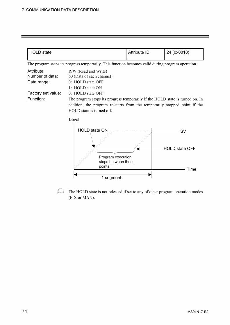
7. COMMUNICATION DATA DESCRIPTION
74 IMS01N17-E2
HOLD state Attribute ID 24 (0x0018)
The program stops its progress temporarily. This function becomes valid during program operation.
Attribute: R/W (Read and Write) Number of data: 60 (Data of each channel) Data range: 0: HOLD state OFF
1: HOLD state ON Factory set value: 0: HOLD state OFF Function: The program stops its progress temporarily if the HOLD state is turned on. In
addition, the program re-starts from the temporarily stopped point if the HOLD state is turned off.
The HOLD state is not released if set to any of other program operation modes (FIX or MAN).
1 segment
Level
SV
Time
HOLD state ON
HOLD state OFF
Program execution stops between these points.

7. COMMUNICATION DATA DESCRIPTION
IMS01N17-E2 75
STEP action Attribute ID 25 (0x0019)
The program progresses by one segment. This function becomes valid during program operation.
Attribute: R/W (Read and Write) Number of data: 60 (Data of each channel) Data range: 0: Not STEP action
1: STEP action execution Factory set value: 0: Not STEP action Function: Used when control needs to be performed by jumping to the next segment.
One segment progresses by the setting per once.
The STEP action cannot be used in the HOLD state.
It is possible to read data items only via Explicit message communication. If this data item is set by the “Controller communication item setting object (0xC7: C7H)” which sets communication data items via polling I/O communication, it becomes the same as that when set at “0.”
Level
SV
Time
Executed from here.
Fast movement
STEP action ON
Segment number 1 2 3 4 5 6

7. COMMUNICATION DATA DESCRIPTION
76 IMS01N17-E2
Program operation start mode Attribute ID 26 (0x001A)
This is a method of starting Set value (SV) when the program starts.
Attribute: R/W (Read and Write) Number of data: 60 (Data of each channel) Data range: 0: Zero start
1: PV start 1 (Fixed time type) 2: PV start 2 (Time shortening type)
Factory set value: 0 Function: Set from which level SV is started when program control is performed.
However, started form the input range low limit for the Voltage/Current input. Number of program execution times Attribute ID 59 (0x003B)
Number of program execution times now under program execution is monitored.
Attribute: RO (Read only) Number of data: 60 (Data of each channel) Data range: 0 to 9999 times Factory set value: ⎯ Pattern end output state Attribute ID 60 (0x003C)
The pattern end output state output at the end of program operation is monitored. It is turned on at the end of program operation. Time to be turned on can be set by setting the pattern end output time.
Attribute: RO (Read only) Number of data: 60 (Data of each channel) Data range: 0: Pattern end output OFF
1: Pattern end output ON Factory set value: ⎯
Level
0 Time
PV start 2
Level 1
Measured value (PV)
Level
0 Time
PV start 1
Zero start
SV SV
• At PV ≤ 0 °C: SV is started from 0 °C.
• At PV ≥ Level 1: SV is started from level 1.
Measured value (PV)
7. COMMUNICATION DATA DESCRIPTION
IMS01N17-E2 77
End state Attribute ID 61 (0x003D)
The state at the end of program operation is monitored. It is turned on at the end of program operation. The state of being turned on is kept until the program is executed again.
Attribute: RO (Read only) Number of data: 60 (Data of each channel) Data range: 0: End state OFF
1: End state ON Factory set value: ⎯ Wait state Attribute ID 62 (0x003E)
Program operation is turned on in the wait state.
Attribute: RO (Read only) Number of data: 60 (Data of each channel) Data range: 0: Wait state OFF
1: Wait state ON Factory set value: ⎯

7. COMMUNICATION DATA DESCRIPTION
78 IMS01N17-E2
7.2 Communication Data of DI Module
Input state of digital input (terminal) Attribute ID 70 (0x0046)
Digital signals (DI channels 1 to 12) input to the terminal board of the DI module are expressed as bit data.
Attribute: RO (Read only) Number of data: 29 (Data of each module) Data range: 0 to 4095 (bit data)
Input state is assigned as a bit image in binary numbers. Bit image: 0000000000000000
Bit 15 ・・・・・・・・・・・・・・・Bit 0 Bit data: 0: OFF (Contact open)
1: ON (Contact closed)
Related parameters: Input state of digital input (connector) (P. 79) Factory set value: ⎯
Bit 0: DI channel 1 Bit 1: DI channel 2 Bit 2: DI channel 3 Bit 3: DI channel 4 Bit 4: DI channel 5 Bit 5: DI channel 6 Bit 6: DI channel 7 Bit 7: DI channel 8
Bit 8: DI channel 9 Bit 9: DI channel 10 Bit 10: DI channel 11 Bit 11: DI channel 12 Bit 12: Unused Bit 13: Unused Bit 14: Unused Bit 15: Unused

7. COMMUNICATION DATA DESCRIPTION
IMS01N17-E2 79
Input state of digital input (connector) 1 Attribute ID 71 (0x0047)
Input state of digital input (connector) 2 Attribute ID 72 (0x0048)
Digital signals (DI channels 13 to 20 and 21 to 28) input to the connector of the DI module are expressed as bit data.
Attribute: RO (Read only) Number of data: 29 (Data of each module) Data range: 0 to 255 (bit data)
Input state is assigned as a bit image in binary numbers. Bit image: 0000000000000000
Bit 15 ・・・・・・・・・・・・・・・Bit 0 Bit data: 0: OFF (Contact open)
1: ON (Contact closed) Related parameters: Input state of digital input (terminal) (P. 78) Factory set value: ⎯
This item is valid only when the X-DI-B module is used.
• Input state of digital input (connector) 1 Bit 0: DI channel 13 Bit 1: DI channel 14 Bit 2: DI channel 15 Bit 3: DI channel 16 Bit 4: DI channel 17 Bit 5: DI channel 18 Bit 6: DI channel 19 Bit 7: DI channel 20 Bit 8 to Bit 15: Unused
• Input state of digital input (connector) 2 Bit 0: DI channel 21 Bit 1: DI channel 22 Bit 2: DI channel 23 Bit 3: DI channel 24 Bit 4: DI channel 25 Bit 5: DI channel 26 Bit 6: DI channel 27 Bit 7: DI channel 28 Bit 8 to Bit 15: Unused

7. COMMUNICATION DATA DESCRIPTION
80 IMS01N17-E2
Error code (DI module) Attribute ID 73 (0x0049)
Error state of DI module is expressed as bit data.
Attribute: RO (Read only) Number of data: 29 (Data of each module) Data range: 0 to 1 (bit data)
Each error state is assigned as a bit image in binary numbers. Bit image: 0000000000000000
Bit 15 ・・・・・・・・・・・・・・・Bit 0 Bit data: 0: OFF
1: ON Factory set value: ⎯
Bit 0: Backup error Bit 1 to Bit 15: Unused

7. COMMUNICATION DATA DESCRIPTION
IMS01N17-E2 81
7.3 Communication Data of DO Module
Output state of digital output (terminal) Attribute ID 74 (0x004A)
Digital signals (DO channels 1 to 12) output from the terminal board of the DO module are expressed as bit data.
Attribute: RO (Read only) Number of data: 29 (Data of each module) Data range: 0 to 4095 (bit data)
Output state is assigned as a bit image in binary numbers. Bit image: 0000000000000000
Bit 15 ・・・・・・・・・・・・・・・Bit 0 Bit data: 0: Output OFF
1: Output ON
Related parameters: Output state of digital output (connector) (P. 82) Factory set value: ⎯
Bit 0: DO channel 1 Bit 1: DO channel 2 Bit 2: DO channel 3 Bit 3: DO channel 4 Bit 4: DO channel 5 Bit 5: DO channel 6 Bit 6: DO channel 7 Bit 7: DO channel 8
Bit 8: DO channel 9 Bit 9: DO channel 10 Bit 10: DO channel 11 Bit 11: DO channel 12 Bit 12: Unused Bit 13: Unused Bit 14: Unused Bit 15: Unused

7. COMMUNICATION DATA DESCRIPTION
82 IMS01N17-E2
Output state of digital output (connector) 1 Attribute ID 75 (0x004B)
Output state of digital output (connector) 2 Attribute ID 76 (0x004C)
Digital signals (DO channels 13 to 20 and 21 to 28) output from the connector of the DO module are expressed as bit data.
Attribute: RO (Read only) Number of data: 29 (Data of each module) Data range: 0 to 255 (bit data)
Output state is assigned as a bit image in binary numbers. Bit image: 0000000000000000
Bit 15 ・・・・・・・・・・・・・・・Bit 0 Bit data: 0: Output OFF
1: Output ON Related parameters: Output state of digital output (terminal) (P. 81) Factory set value: ⎯
This item is valid only when the X-DO-B module is used.
• Output state of digital output (connector) 1 Bit 0: DO channel 13 Bit 1: DO channel 14 Bit 2: DO channel 15 Bit 3: DO channel 16 Bit 4: DO channel 17 Bit 5: DO channel 18 Bit 6: DO channel 19 Bit 7: DO channel 20 Bit 8 to Bit 15: Unused
• Output state of digital output (connector) 2 Bit 0: DO channel 21 Bit 1: DO channel 22 Bit 2: DO channel 23 Bit 3: DO channel 24 Bit 4: DO channel 25 Bit 5: DO channel 26 Bit 6: DO channel 27 Bit 7: DO channel 28 Bit 8 to Bit 15: Unused

7. COMMUNICATION DATA DESCRIPTION
IMS01N17-E2 83
Manual output setting of digital output (terminal) Attribute ID 77 (0x004D)
Any manual output (DO channel 1 to 12) from the terminal board on the DO module is set by bit data.
Attribute: R/W (Read and Write) Number of data: 29 (Data of each module) Data range: 0 to 4095 (bit data)
Manual output setting is assigned as a bit image in binary numbers. Bit image: 0000000000000000
Bit 15 ・・・・・・・・・・・・・・・Bit 0 Bit data: 0: Output OFF
1: Output ON
Related parameters: Manual output setting of digital output (connector) (P. 84) Factory set value: 0
The manual output setting of digital output is valid only when “DO function selection” is 0. “DO function selection” can be set in the host communication of the DO module.
For host communication, refer to the Module Type Controller SRX Communication Instruction Manual (IMS01N01-E ).
Bit 0: DO channel 1 Bit 1: DO channel 2 Bit 2: DO channel 3 Bit 3: DO channel 4 Bit 4: DO channel 5 Bit 5: DO channel 6 Bit 6: DO channel 7 Bit 7: DO channel 8
Bit 8: DO channel 9 Bit 9: DO channel 10 Bit 10: DO channel 11 Bit 11: DO channel 12 Bit 12: Unused Bit 13: Unused Bit 14: Unused Bit 15: Unused

7. COMMUNICATION DATA DESCRIPTION
84 IMS01N17-E2
Manual output setting of digital output (connector) 1 Attribute ID 78 (0x004E)
Manual output setting of digital output (connector) 2 Attribute ID 79 (0x004F)
Any manual output (DO channel 13 to 20 and DO channel 21 to28) from the connector on the DO module is set by bit data.
Attribute: R/W (Read and Write) Number of data: 29 (Data of each module) Data range: 0 to 255 (bit data)
Manual output setting is assigned as a bit image in binary numbers. Bit image: 0000000000000000
Bit 15 ・・・・・・・・・・・・・・・Bit 0 Bit data: 0: Output OFF
1: Output ON Related parameters: Manual output setting of digital output (terminal) (P. 83) Factory set value: 0
This item is valid only when the X-DO-B module is used.
The manual output setting of digital output is valid only when “DO function selection” is 0. “DO function selection” can be set in the host communication of the DO module.
For host communication, refer to the Module Type Controller SRX Communication Instruction Manual (IMS01N01-E ).
• Manual output setting of digital output (connector) 1 Bit 0: DO channel 13 Bit 1: DO channel 14 Bit 2: DO channel 15 Bit 3: DO channel 16 Bit 4: DO channel 17 Bit 5: DO channel 18 Bit 6: DO channel 19 Bit 7: DO channel 20 Bit 8 to Bit 15: Unused
• Manual output setting of digital output (connector) 2 Bit 0: DO channel 21 Bit 1: DO channel 22 Bit 2: DO channel 23 Bit 3: DO channel 24 Bit 4: DO channel 25 Bit 5: DO channel 26 Bit 6: DO channel 27 Bit 7: DO channel 28 Bit 8 to Bit 15: Unused

7. COMMUNICATION DATA DESCRIPTION
IMS01N17-E2 85
Error code (DO module) Attribute ID 80 (0x0050)
Error state of DO module is expressed as bit data.
Attribute: RO (Read only) Number of data: 29 (Data of each module) Data range: 0 to 1 (bit data)
Each error state is assigned as a bit image in binary numbers. Bit image: 0000000000000000
Bit 15 ・・・・・・・・・・・・・・・Bit 0 Bit data: 0: OFF
1: ON Factory set value: ⎯
Bit 0: Backup error Bit 1 to Bit 15: Unused

86 IMS01N17-E2
8. USAGE EXAMPLE
In this Chapter, an example of using DeviceNet communication is explained when the SRX is connected to a PLC as a master. 8.1 Handling Procedures
Preparations of configuration instrument
SRX hardware setting
SRX wiring
SRX initial setting
DeviceNet wiring
Programming
Refer to 8.2 System Configuration (P. 87).
For the X-TIO-J module, refer to APPENDIX C.1 Terminal Configuration (P. 119). For other modules, refer to the Instruction Manual of each module.
For network laying requirement of DeviceNet/method, referto Instruction Manual of master product or website ofODVA (Open DeviceNet Vender Association). http://www.odva.org
Refer to 4.1.3 DIP switch 1 setting (P. 8), 4.1.4 Internaldata bus termination resistor setting (P. 9) and 4.2Module Address Setting (P. 10).
Refer to 4.3 Initializing Module (P. 12), 4.1.1 Nodeaddress setting (P. 6), 4.1.2 DeviceNet communicationspeed setting (P. 7) and 8.3 Hardware Setting (P. 88).
Refer to 8.3 Hardware Setting (P. 88) and PLC Instruction Manual.
Refer to 6. DeviceNet COMMUNICATIONS (P. 19) andthe Instruction Manual of Configuration Tool.
Refer to 8.4 Sample Programs (P. 89) and PLC InstructionManual.
Communication items setting
PLC setting
• For wiring of SRX, refer to 5. WIRING (P. 16). • For wiring of PLC, refer to PLC Instruction Manual.

8. USAGE EXAMPLE
IMS01N17-E2 87
8.2 System Configuration Use instruments Module type controller SRX − Temperature control module for DeviceNet: X-TIO-J
PLC − SYSMAC CJ (OMRON product)
CPU unit: CJ1M, DeviceNet master unit: CJ1W-DRM21 or
− Control Logix 5550 [Rockwell Inc. (Allen-Bradley) ] CPU module: 1756-L1, LINK module (DeviceNet): 1756-DNB Personal computer
The configuration tool must be installed in a personal computer.
PLC (Master)
DeviceNet
X-TIO-J module (Slave)
Personal computer

8. USAGE EXAMPLE
IMS01N17-E2 88
8.3 Hardware Setting Set each hardware’s as the following. PLC setting
Set PLC in requirement of the following.
[DeviceNet communication requirement] • Node address: 0 • DeviceNet communication speed: 125 kbps • Unit Number: 0
For setting method, refer to Instruction Manual for PLC. SRX setting
Set X-TIO-J module in requirement of the following.
[DeviceNet communication requirement] • Node address: 1 • DeviceNet communication speed: 125 kbps • Number of communication data: 8 words
For setting method, refer to 4.1 DeviceNet Communication Setting (P. 6).
The number of communication data items when conducting polling I/O communication can also be set via Explicit message communication, or by the configuration tool or rotary switch. For details, refer to 4.4 Communication Environment Setting by Rotary Switch (P. 13),
Communication parameter setting by configuration tool (P. 24), or Communication parameter setting by Explicit message communication (P. 32).

8. USAGE EXAMPLE
IMS01N17-E2 89
8.4 Sample Programs 8.4.1 Polling I/O communication (When the SYSMAC CJ)
Polling I/O communication is called “Remote I/O communication” in OMRON PLC related instruction manuals.
Communication requirement Contents of communication parameter setting
Communication data items: Measured data item (IN): Measured value (PV) [Attribute ID: 1] Set data item (OUT): Set value (SV) [Attribute ID: 12] Number of communication channels: 2 channels Number of communication data items: 8 words
The above communication parameters can be set via Explicit message communication or by the configuration tool. For details, refer to Communication parameter setting by configuration tool (P. 24), or Communication parameter setting by Explicit message communication (P. 32).
Memory allocation
Allocate the memory by using the configuration tool. Allocation method: Manual allocation Data area: Measured data item (IN) area: D00000 to D00007 (8 words) Set data item (OUT) area: D10000 to D10007 (8 words)
Data which a master receives [Response: measured data items (IN)]
No. Items Storage location of read data
1 Alarm state (channel 1 to 16) D00000
2 Alarm state (channel 17 to 32) D00001
3 Alarm state (channel 33 to 48) D00002
4 Alarm state (channel 49 to 60) D00003
5 Control RUN/STOP state (module 1 to 16) [Data of each module]
D00004
6 Control RUN/STOP state (module 17 to 32) [Data of each module]
D00005
7 Measured value (PV) channel 1 D00006
8 Measured value (PV) channel 2 D00007
Communication data No. 1 to 6 (corresponding to 6 words) are fixed communication data items.

8. USAGE EXAMPLE
IMS01N17-E2 90
Data to send from a master [Request: set data items (OUT)]
No. Items Data contents Storage location of write data
1 Setting state selection (channel 1 to 16)
As there are two communication channels, only bit 0 (channel 1) and bit 1 (channel 2) corresponding to communication data No.1 can be used.
0000000000000000
Bit 1 Bit 0 Data 0: Setting disabled 1: Setting enabled [Decimal number: 0 to 3]
D10000
2 Setting state selection (channel 17 to 32)
0 D10001
3 Setting state selection (channel 33 to 48)
0 D10002
4 Setting state selection (channel 49 to 60)
0 D10003
5 Control RUN/STOP selection (module 1 to 16) [Data of each module]
As one module is used, only bit 0 (module 1) corresponding to data No. 5 can be used.
0000000000000000 Bit 0
Data 0: STOP 1: RUN [Decimal number: 0 to 1]
D10004
6 Control RUN/STOP selection (module 17 to 32) [Data of each module]
0 D10005
7 Set value (SV) channel 1 100 D10006
8 Set value (SV) channel 2 200 D10007
Communication data No. 1 to 6 (corresponding to 6 words) are fixed communication data items.

8. USAGE EXAMPLE
IMS01N17-E2 91
Sample program (ladder) Measured data items (IN)
Data corresponding to the measured data item (IN) can be checked only by reading the data storage register assigned by the configuration tool. Set data items (OUT)
The following procedure is required for setting data to the SRX.
1. Sets 100 to “Set value (SV): D10006” of temperature control channel 1. 2. Sets 200 to “Set value (SV): D10007” of temperature control channel 2. 3. Set Bit 0 (TIO channel 1) and Bit 1 (TIO channel 2) for “Setting state selection: D10000” to
“1: Setting enabled.” 4. Set Bit 0 (TIO channel 1) and Bit 1 (TIO channel 2) for “Setting state selection: D10000” to
“0: Setting disabled” after a lapse of preset time (Ex.: 200 ms). 5. Sets 0 (reset) to “Set value (SV): D10006” of temperature control channel 1. 6. Sets 0 (reset) to “Set value (SV): D10007” of temperature control channel 2.
MOV &100
D10006
1.00
MOV &200
D10007
1.00 1.00 T0000
TIMH 0000 #20
MOV #3
D100001.00
DIFD 1.01
MOV #0
D10000
1.01
MOV #0
D10007
MOV #0
D10006
Sets 100 to D10006 when relay 1.00 is turned ON.
Activate timer T0000 by setting to 200 ms when relay 1.00 is turned ON
Differentiating the fall signal of the relay1.00 activates the relay 1.01.
Sets 200 to D10007 when relay 1.00 is turned ON.
Sets 0003H (Bit 0: 1, Bit 1: 1) to D10000 when relay 1.00 is turned ON
Sets 0000H (bit 0: 0, bit 1: 0) to D10000 when relay 1.01 is turned ON
Sets 0 (data reset) to D10006 when relay 1.01 is turned ON.
Sets 0 (data reset) to D10007 when relay 1.01 is turned ON.

8. USAGE EXAMPLE
IMS01N17-E2 92
8.4.2 Explicit message communication (When the SYSMAC CJ) In order to conduct Explicit message communication using the OMRON SYSMAC CJ PLC, the FINS command for FINS communication (communication protocol developed by OMRON) is used.
For the FINS command and the CMND instruction, refer to the Instruction Manual of OMRON SYSMAC CJ PLC.
Communication requirement
The vendor code is read from the SRX (slave). (RKC vendor code: 394 = 018AH)
• Using the “Explicit message send” command (2801) of FINS command. • The “CMND instruction” is used to send FINS commands. • Write location of request data from the PLC (master): On and after D01000 • Storage location of response data from the SRX (slave): On and after D02000 • The completion code is stored in D00006 when execution of CMND has been completed abnormally
and then the command is executed again. • When an Explicit message is sent by the SYSMAC CJ, the send location of the FINS command is
assigned to the DeviceNet master unit of its own node instead of the actual send location (SRX). The SRX node address is specified within Explicit message send command data.
FINS command
CMND
CPU unit
DeviceNet master unit Unit No.: 0 Node address: 05 Unit address: FEH or 10H
SYSMAC CJ
Explicit message
SRX
Node address: 11

8. USAGE EXAMPLE
IMS01N17-E2 93
Command data format Command data format at communicating by an Explicit message with SYSMAC CJ is shown with the following. [Request data format from the PLC (master)]
28 01 534 bytes max.
[Response data format]
• Normal response
28 01 00 00 534 bytes max.
• Error response
28 01 00 00 94 • Cannot be sent/Timeout
28 01
As this response (Cannot be sent/Timeout) is an error response sent to the CPU unit from the DeviceNet master unit of the SYSMAC CJ, this is not an error in DeviceNet communication.
Service data
Service data
Error code
Instance ID
No. of bytes received
No. of bytes received
Object class ID
Responsecode
Responsecode
Responsecode
Command code
Command code
Command code
Command code
Service code
Service code
14H + 80H = 94H 14H: Error response 80H: Response data
Service code (94H):
Destination node address
Source node address
Source node address

8. USAGE EXAMPLE
IMS01N17-E2 94
Description of CMND [CMND S D C] Command data is set in order starting with the word specified for the CMND operand S (first command word) and continuing with words with higher addresses in I/O memory in the command block format.
15 0
C+0
15 0
C+1
15 0
C+2 0 0
15 0
C+3
15 10 8 3 0
C+4 0 0 0 0 0
15 0
C+5
CMND S
S: First command word D: First response word C: First control data word
D C
Number of command bytes to send 0000H to 02E1H (0 to 542 bytes)
Number of response data bytes to receive 0000H to 02E1H (0 to 542 bytes)
Destination network address 00H: Local network 01H to 7FH: 1 to 127
Destination unit FINS address FEH: The local Unit 10H to 1FH: Unit numbers + 10H Destination node address
00 to 3FH: 0 to 63
Number of retries: 0H to FH (0 to 15 times)
Transmission port number: 0 to 7
0: Response returned 1: No response.
Response monitoring time 0000H: 2 seconds 0001H to FFFFH: 0.1 to 6553.5 seconds

8. USAGE EXAMPLE
IMS01N17-E2 95
[Sample program] S D01000+ 0 2801H Command code (2801H)
+ 1 0B0EH Slave node address: 11 (0BH), Service code (0EH) + 2 0001H Object class ID (0001H) + 3 0001H Instance ID (0001H) + 4 0100H Attribute ID (01H)
D D02000 First response word at local node
C D00000+ 0 0009H Number of command bytes (9 bytes) + 1 000AH Number of response bytes (10 bytes) + 2 0001H Destination network address (1) + 3 05FEH Destination node address (5), Destination unit address: FEH (or 10H) + 4 0000H Response (0), Transmission port No.0 (0), No retries (0H) + 5 0064H Response monitoring time: 10.0 seconds (64H)
Response
D02000+ 0 2801H Command code (2801H) + 1 0000H Response code (0000H) + 2 0004H Number of bytes received (0004H) + 3 0B8EH Response source node address: 11 (0BH), Normal completion (8EH) + 4 8A01H Vendor code stored from high to low byte (RKC vendor code: 394 = 018AH)

8. USAGE EXAMPLE
IMS01N17-E2 96
Sample program (ladder)
Continued on the next page.
Sets 0000 in order to initialize D00000 to D02999. A20011: First cycle flag
Places 0001 in CIO 0000.
Places 0001 into D00002. Destination network address: 01H
Places 0064 into D00005. Response monitoring time: 10.0 seconds
Places 0009 into D00000. Number of command bytes: 9 bytes
Places 2801 into D01000. Explicit message send command
Places 0B0E into D01001. Slave node address: 11 (0BH) Service code: 0EH
Places 0001 into D01002. Object class ID: 0001H
Places 0001 into D01003. Instance ID: 0001H
Places 0100 into D01008. Attribute ID: 01H
A20011
MOV #00010000
BSET#0000
D00000D02999
MOV #0001
D00002
MOV #05FE
D00003
MOV #0000
D00004
MOV #0064
D00005
MOV #0009
D00000
MOV #2801
D01000
MOV #0B0ED01001
MOV #0001
D01002
MOV #0001
D01003
MOV #0100
D01004
Places 000A into D00001. Number of response bytes: 10 bytes
MOV #000A
D00001
Places 05FE into D00003. Destination node address: 05HDestination unit FINS address: FEH
Places 0000 into D00004. Response (0), Transmission port No.0, No retries (0)
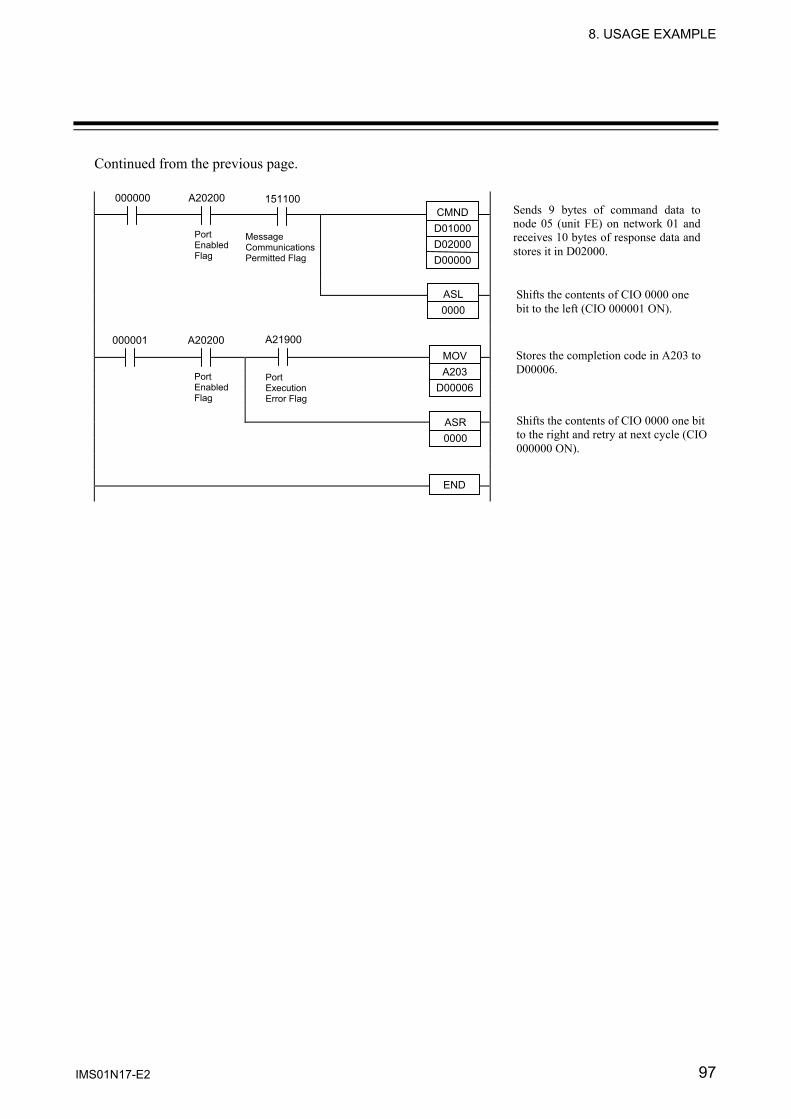
8. USAGE EXAMPLE
IMS01N17-E2 97
Continued from the previous page.
000000 A20200 CMNDD01000D02000D00000
ASR 0000
Shifts the contents of CIO 0000 one bit to the right and retry at next cycle (CIO000000 ON).
000001
Shifts the contents of CIO 0000 one bit to the left (CIO 000001 ON).
Sends 9 bytes of command data tonode 05 (unit FE) on network 01 andreceives 10 bytes of response data andstores it in D02000.
Stores the completion code in A203 to D00006.
A20200
END
ASL 0000
MOV A203
D00006
Port Enabled Flag
Message Communications Permitted Flag
151100
A21900
Port Enabled Flag
Port Execution Error Flag

98 IMS01N17-E2
9. TROUBLESHOOTING
This section explains probable causes and solutions if any abnormality occurs in the instrument. For any inquiries or to confirm the specifications of the product, please contact RKC sales office or the agent. If it is necessary to replace a device, always strictly observe the warnings below.
• All wiring must be completed before power is turned on to prevent electric shock, instrument failure, or incorrect action.
• The power must be turned off before repairing work for input break and output failure including replacement of sensor, contactor or SSR, and all wiring must be completed before power is turned on again.
• Do not separate the module mainframe from the terminal base with the power turned on. If so, instrument failure may result.
When replacing the module with a new one, always use the module with the same model code. If the module is replaced, it is necessary to re-set each data item.
CAUTION
To prevent electric shock or instrument failure, always turn off the system power before replacing the instrument.
To prevent electric shock or instrument failure, always turn off the power before mounting or removing the instrument.
To prevent electric shock or instrument failure, do not turn on the power until all wiring is completed. Make sure that the wiring is correct before applying power to the instrument.
To prevent electric shock or instrument failure, do not touch the inside of the instrument.
All wiring must be performed by authorized personnel with electrical experience in this type of work.
WARNING!

9. TROUBLESHOOTING
IMS01N17-E2 99
Problem Possible cause Solution
No response (DeviceNet)
Wrong connection, no connection or disconnection of the DeviceNet communication cable
Confirm the connection method or condition and connect correctly
Breakage, wrong wiring, or imperfect contact of the DeviceNet communication cable
Confirm the wiring or connector and repair or replace the wrong one
Communication speed setting of master (PLC) and the slave (SRX) is mismatch
Confirm the communication speed setting and set that correctly
Wrong node address setting Confirm the address setting and set that correctly
• NS (or NET) lamp OFF
• MS (or MOD) lamp ON (Green)
Wait for completion of node address duplication check with a master
If only the SRX is in this state though both of the NS/MS (NET/MOD) lamps are lit in green, re-start after checking that each communication speed is the same
MS (or MOD) lamp flashes (Green)
Module configuration error Check an error occurring in any module other than the X-TIO-J module and then initialize the module
MS (or MOD) lamp ON (Red)
Memory backup error Replace X-TIO-J module
• NS (or NET) lamp ON (Red)
Node address duplication Re-start after the re-setting is made so that no node address is duplicated
• MS (or MOD) lamp ON (Green)
Bus off status (communication stop by data abnormality frequent occurrence)
Re-start after checking the following items. • Does the speed coincide with the
master communication speed ? • Is not the DeviceNet communication
cable connected yet, incorrectly connected or removed ?
• Is the length of the DeviceNet communication cable appropriate ?
• Are termination resistors (121 Ω) connected only to both ends of the trunk line ?
• Does much noise exist ?
Breakdown of communication device
Replace X-TIO-J module
Continued on the next page.

9. TROUBLESHOOTING
IMS01N17-E2 100
Continued from the previous page.
Problem Possible cause Solution
• NS (or NET) lamp flashes (Red)
• MS (or MOD) lamp ON (Green)
DeviceNet communication I/O connection time-out state
• Set the I/O connection Expected packet rate (class: 0x05, instance: 2, attribute: 9) to 0 (No time-out) or set it to a sufficiently large value.
• Lengthen the master I/O message communication cycle time.
• NS (or NET) lamp flashes (Green)
• MS (or MOD) lamp ON (Green)
DeviceNet communication Communication have not yet been established
It is checked whether or not the X-TIO-J module is registered to the master as a slave. Re-start after checking the following items. • Does the speed coincide with the
master communication speed ? • Is not the DeviceNet communication
cable connected yet, incorrectly connected or removed ?
• Is the length of the DeviceNet communication cable appropriate ?
• Are termination resistors (121 Ω) connected only to both ends of the trunk line ?
• Does much noise exist ?

IMS01N17-E2 101
APPENDIX A. DEVICE PROFILES
A device profile is the specification that defined each necessary parameter with DeviceNet. Use it after understanding contents of a device profile of SRX fully when connected to a master. A.1 Basic Data General device data
Conforms to DeviceNet specification
Volume I -Release 2.0 Volume II -Release 2.0
Vender name RKC INSTRUMENT INC. (Vender ID = 394) Device profile name Generic Device Product catalog number Instruction manual number: IMS01N17-E (English)
IMS01N17-J (Japanese) Product revision 1.0
Physical conformance data
Network power consumption 2 mA @ 11 V DC 4 mA @ 24 V DC
Connector type Open-style connector or Micro-style connector Insulated physical layer Provided LEDs supported Module, Network MAC ID setting Rotary switch (Node address setting) Default MAC ID 63 Communication speed setting Rotary switch (DeviceNet communication speed setting) Communication speed supported 125 kbps, 250 kbps, 500 kbps
Communication data
Predefined master/slave connection set
Group 2 Only server
Dynamic connection supported (UCMM)
Not supported
Fragmented Explicit Messaging None

APPENDIX A. DEVICE PROFILES
IMS01N17-E2 102
A.2 Object Mounting Identity Object (0x01: 01H) Object class
Attributes Not supported
Services Not supported
Object instance
ID Description Get Set Type Value Attributes 1 Vender Yes No UINT 394 2 Product type Yes No UINT 0 3 Product code Yes No UINT 3 4 Revision
Major revision Minor revision
Yes No USINT USINT
1 1
5 Status (bits supported) Yes No WORD Note 6 Serial number Yes No UDINT 7 Product name
Length Name
Yes No USINT STRING
3 SRX
DeviceNet service Parameter option Services 0x05 Reset 0 0x0E Get_Attribute_Single None
Note: A bit layout of “Status” Bit 0: Owned Bit 7: Become 1 when controller state of SRX become abnormal Memory backup error Module configuration error Bit 1 to 6 and Bit 8 to 15: Unused

APPENDIX A. DEVICE PROFILES
IMS01N17-E2 103
Message Router Object (0x02: 02H) Object class
Attributes Not supported
Services Not supported
Object instance
Attributes Not supported
Services Not supported

APPENDIX A. DEVICE PROFILES
IMS01N17-E2 104
DeviceNet Object (0x03: 03H) Object class
ID Description Get Set Type Value Attributes 1 Revision Yes No UINT 2
DeviceNet service Parameter option Services 0x0E Get_Attribute_Single None
Object instance
ID Description Get Set Type Value Attributes 1 MAC ID Yes No USINT 0 to 63 2 Baud rate Yes No USINT 0 to 2 3 BOI Yes No BOOL 0 4 Bus-off counter Yes Yes USINT 5 Allocation information
Allocation choice byte Master’s MAC ID
Yes No BYTE USINT
6 MAC ID switch changed Yes No BOOL 0, 1 7 Baud rate switch changed Yes No BOOL 0, 1 8 MAC ID switch value Yes No USINT 0 to 63 9 Baud rate switch value Yes No USINT 0 to 2
DeviceNet service Parameter option Services 0x0E Get_Attribute_Single None 0x10 Set_Attribute_Single None 0x4B Allocate_Master/Slave_
Connection_Set None
0x4C Release_Group_2_ Identifire_Set
None

APPENDIX A. DEVICE PROFILES
IMS01N17-E2 105
Assembly Object (0x04: 04H) Object class
ID Description Get Set Type Value Attributes 1 Revision Yes No UINT 2
DeviceNet service Parameter option Services 0x0E Get_Attribute_Single None
Object instance 100
ID Description Get Set Type Value Attributes 3 Data Yes No
DeviceNet service Parameter option Services 0x0E Get_Attribute_Single None
Object instance 101
ID Description Get Set Type Value Attributes 3 Data Yes Yes
DeviceNet service Parameter option Services 0x0E Get_Attribute_Single
0x10 Set_Attribute_Single None None

APPENDIX A. DEVICE PROFILES
IMS01N17-E2 106
Connection Object (0x05: 05H) Object class
Attributes Not supported
Services Not supported Number of maximum possible active connection
1
Object instance 1
Section Information Number of maximum instance
Instance type Explicit Message 1 Production trigger Cyclic Transport type Server Transport class 3
ID Description Get Set Type Value Attributes 1 State Yes No USINT 2 Instance type Yes No USINT 0x00 3 Transport class trigger Yes No BYTE 0x83 4 Produced connection ID Yes No UINT 5 Consumed connection ID Yes No UINT 6 Initial comm. Characteristics Yes No BYTE 0x21 7 Produced connection size Yes No UINT 7 8 Consumed connection size Yes No UINT 7 9 Expected packet rate Yes Yes UINT Default: 2500 12 Watchdog time-out action Yes Yes USINT 1, 3 13 Produced connection path length Yes No UINT 0 14 Produced connection path Yes No (null) 15 Consumed connection path length Yes No UINT 0 16 Consumed connection path Yes No (null)
DeviceNet service Parameter option Services 0x05 Reset None 0x0E Get_Attribute_Single None 0x10 Set_Attribute_Single None
Continued on the next page.

APPENDIX A. DEVICE PROFILES
IMS01N17-E2 107
Continued from the previous page. Object instance 2
Section Information Number of maximum instance
Instance type Polled I/O 1 Production trigger Cyclic Transport type Server Transport class 2
ID Description Get Set Type Value Attributes 1 State Yes No USINT 2 Instance type Yes No USINT 0x01 3 Transport class trigger Yes No BYTE 0x82 4 Produced connection ID Yes No UINT 5 Consumed connection ID Yes No UINT 6 Initial comm. Characteristics Yes No BYTE 0x01 7 Produced connection size Yes No UINT Note 8 Consumed connection size Yes No UINT Note 9 Expected packet rate Yes Yes UINT Default: 0 12 Watchdog time-out action Yes No USINT 0 13 Produced connection path length Yes No UINT 6 14 Produced connection path
Logic Segment, Class Class Number Logic Segment, Instance Instance Number Logic Segment, Attributes Attributes Number
Yes No USINTUSINTUSINTUSINTUSINTUSINT
0x20 0x04 0x24 0x64 0x30 0x03
15 Consumed connection path length Yes No UINT 6 16 Consumed connection path
Logic Segment, Class Class Number Logic Segment, Instance Instance Number Logic Segment, Attributes Attributes Number
Yes No USINTUSINTUSINTUSINTUSINTUSINT
0x20 0x04 0x24 0x65 0x30 0x03
DeviceNet service Parameter option Services 0x05 Reset None 0x0E Get_Attribute_Single None 0x10 Set_Attribute_Single None
Note: Make the setting by any of the following methods. (The value is validated with the power turned on) • Select with the DIP switch 1. [16 (8 words), 52 (26 words), 92 (46 words) or 200 (100 words)] • Set with number setting (attribute ID: 65 and 66) of communication data of controller object
(0x64).

APPENDIX A. DEVICE PROFILES
IMS01N17-E2 108
Controller Object (0x64: 64H) Object class
Attributes Not supported Services Not supported
Object instance ( : 1 to 60)
ID Description Get Set Type Value Attributes 1 Measured value (PV) Yes No INT Refer to P. 45 2 Set value monitor Yes No INT Refer to P. 45 3 Manipulated output value Yes No INT Refer to P. 45 4 Current transformer (CT) input value Yes No UINT Refer to P. 45 5 TIO state 1 Yes No WORD Refer to P. 46 6 TIO state 2 Yes No WORD Refer to P. 47 7 Execution pattern Yes Yes UINT Refer to P. 71 8 Execution segment Yes No UINT Refer to P. 71 9 Segment remaining time Yes No UINT Refer to P. 71 10 Time signal output state 1 Yes No WORD Refer to P. 72 11 Time signal output state 2 Yes No WORD Refer to P. 72 12 Set value (SV) Yes Yes INT Refer to P. 48 13 Event 1 set value Yes Yes INT Refer to P. 48 14 Event 2 set value Yes Yes INT Refer to P. 48 15 Heater break alarm (HBA) set value Yes Yes UINT Refer to P. 48 16 Proportional band Yes Yes UINT Refer to P. 50 17 Integral time Yes Yes UINT Refer to P. 50 18 Derivative time Yes Yes UINT Refer to P. 50 19 Operation mode Yes Yes UINT Refer to P. 51 20 PID/AT transfer Yes Yes UINT Refer to P. 52 21 Control RUN/STOP transfer 1 Yes Yes UINT Refer to P. 53 22 Program operation mode Yes Yes UINT Refer to P. 73 23 Unused 2 No No INT ⎯ 24 HOLD state Yes Yes UINT Refer to P. 74 25 STEP action 2 Yes Yes UINT Refer to P. 75 26 Program operation start mode Yes Yes UINT Refer to P. 76 27 Control response parameters Yes Yes UINT Refer to P. 53
1 If “Control RUN/STOP” is set as the setting data item (OUT) by the “Controller communication
item setting object (0xC7: C7H)” which sets communication data items via polling I/O communication, it becomes the same as that when set at “0.” If set as the measured data item (IN), it can be used as is.
2 If this data item is set as a measured data item (IN) or set data item (OUT) by the “Controller communication item setting object (0xC7: C7H)” which sets communication data items via polling I/O communication, it becomes the same as that when set at “0.” In addition, any data item set hereafter is invalidated.
Continued on the next page.

APPENDIX A. DEVICE PROFILES
IMS01N17-E2 109
Continued from the previous page.
ID Description Get Set Type Value Attributes 28 PV bias Yes Yes INT Refer to P. 54 29 Manual output value Yes Yes INT Refer to P. 54 30 Output limiter low Yes Yes INT Refer to P. 54 31 Output limiter high Yes Yes INT Refer to P. 54 32 Proportional cycle time Yes Yes UINT Refer to P. 55 33 Digital filter Yes Yes UINT Refer to P. 55 34 Number of heater break alarm (HBA) delay
times Yes Yes UINT Refer to P. 55
35 Hot/Cold start selection Yes Yes UINT Refer to P. 56 36 Start determination point Yes Yes UINT Refer to P. 57 37 Input error determination point (high) Yes Yes INT Refer to P. 57 38 Input error determination point (low) Yes Yes INT Refer to P. 57 39 Action at input error (high) Yes Yes UINT Refer to P. 58 40 Action at input error (low) Yes Yes UINT Refer to P. 58 41 Manipulated output value at input error Yes Yes INT Refer to P. 58 42 AT differential gap time Yes Yes UINT Refer to P. 59 43 AT bias Yes Yes INT Refer to P. 60 44 Remote/Local transfer Yes Yes UINT Refer to P. 60 45 Event LED mode setting Yes Yes UINT Refer to P. 61 46 Digital input setting 1 (RESET) Yes Yes UINT Refer to P. 62 47 Digital input setting 2 (RUN) Yes Yes UINT Refer to P. 62 48 Digital input setting 3 (FIX) Yes Yes UINT Refer to P. 62 49 Digital input setting 4 (MAN) Yes Yes UINT Refer to P. 62 50 Digital input setting 5 (HOLD) Yes Yes UINT Refer to P. 63 51 Digital input setting 6 (STEP) Yes Yes UINT Refer to P. 64 52 Digital input setting 7
(Program pattern selection) Yes Yes UINT Refer to P. 65
53 Digital input setting 8 (AT/PID) Yes Yes UINT Refer to P. 66 54 Control loop break alarm (LBA) use selection Yes Yes UINT Refer to P. 67 55 Control loop break alarm (LBA) time Yes Yes UINT Refer to P. 67 56 LBA deadband (LBD) Yes Yes UINT Refer to P. 68 57 Integral/Derivative time decimal point position 1 Yes Yes UINT Refer to P. 69 58 Unused 2 No No INT ⎯ 59 Number of program execution times Yes No UINT Refer to P. 76 60 Pattern end output state Yes No UINT Refer to P. 76 61 End state Yes No UINT Refer to P. 77 62 Wait state Yes No UINT Refer to P. 77
1 To validate the set value being changed, change this parameter, then turn the power OFF and then ON. 2 If this data item is set as a measured data item (IN) or set data item (OUT) by the “Controller
communication item setting object (0xC7: C7H)” which sets communication data items via polling I/O communication, it becomes the same as that when set at “0.” In addition, any data item set hereafter is invalidated.
Continued on the next page.

APPENDIX A. DEVICE PROFILES
IMS01N17-E2 110
Continued from the previous page.
ID Description Get Set Type Value Attributes 63 Number of communication channels 1 Yes Yes UINT Refer to P. 69 64 Number of connected TIO channels 1, 2 Yes No UINT Refer to P. 69 65 Number of communication measured data
items (IN) 1 Yes Yes UINT Refer to P. 70
66 Number of communication set data items (OUT) 1
Yes Yes UINT Refer to P. 70
67 Unused 3 No No INT ⎯ 68 Unused 3 No No INT ⎯ 69 Unused 3 No No INT ⎯ 70 Input state of digital input (terminal) Yes No UINT Refer to P. 78 71 Input state of digital input (connector) 1 Yes No UINT Refer to P. 79 72 Input state of digital input (connector) 2 Yes No UINT Refer to P. 79 73 Error code (DI module) Yes No WORD Refer to P. 80 74 Output state of digital output (terminal) Yes No UINT Refer to P. 81 75 Output state of digital output (connector) 1 Yes No UINT Refer to P. 82 76 Output state of digital output (connector) 2 Yes No UINT Refer to P. 82 77 Manual output setting of digital output
(terminal) Yes Yes UINT Refer to P. 83
78 Manual output setting 1 of digital output (connector)
Yes Yes UINT Refer to P. 84
79 Manual output setting 2 of digital output (connector)
Yes Yes UINT Refer to P. 84
80 Error code (DO module) Yes No WORD Refer to P. 85 81 to 120 Unused 3 No No INT ⎯
DeviceNet service Parameter option Services 0x0E Get_Attribute_Single None 0x10 Set_Attribute_Single None
1 It is validated only via Explicit message communication. If this data item is set as a measured data
item (IN) or set data item (OUT) by the “Controller communication item setting object (0xC7: C7H)” which sets communication data items via polling I/O communication, it becomes the same as that when set at “0.” In addition, any data item set hereafter is invalidated.
2 The X-TIO-J module starts collecting data on connected modules just after the power is turned on, and communication is validated after data collection is finished. If “the number of connected TIO channels” is read during data collection, “0” is returned. Therefore, the communication enable state after the power is turned on can be checked as far as “the number of connected TIO channels” is monitored.
3 If this data item is set as a measured data item (IN) or set data item (OUT) by the “Controller communication item setting object (0xC7: C7H)” which sets communication data items via polling I/O communication, it becomes the same as that when set at “0.” In addition, any data item set hereafter is invalidated.
Any object instance from 1to 60 corresponds to any TIO channel from 1 to 60. However if a unit of communication is for each module, any object instsnce from 1 to 30 (or 29) corresponds to any module No. from 1 to 30 (or 29). In addition, if a unit of communication is for a group of these modules, only object instance 1 is validated.

APPENDIX A. DEVICE PROFILES
IMS01N17-E2 111
Controller Communication Item Setting Object (0xC7: C7H) Object class
Attributes Not supported Services Not supported
Object instance 1
ID Description Get Set Type Value (Default) Attributes 1 Measured data item (IN) 1 ○ ○ UINT 1 2 Measured data item (IN) 2 ○ ○ UINT 0 3 Measured data item (IN) 3 ○ ○ UINT 0 4 Measured data item (IN) 4 ○ ○ UINT 0 5 Measured data item (IN) 5 ○ ○ UINT 0 6 Measured data item (IN) 6 ○ ○ UINT 0 7 Measured data item (IN) 7 ○ ○ UINT 0 8 Measured data item (IN) 8 ○ ○ UINT 0 9 Measured data item (IN) 9 ○ ○ UINT 0 10 Measured data item (IN) 10 ○ ○ UINT 0 11 Set data item (OUT) 1 ○ ○ UINT 12 12 Set data item (OUT) 2 ○ ○ UINT 0 13 Set data item (OUT) 3 ○ ○ UINT 0 14 Set data item (OUT) 4 ○ ○ UINT 0 15 Set data item (OUT) 5 ○ ○ UINT 0 16 Set data item (OUT) 6 ○ ○ UINT 0 17 Set data item (OUT) 7 ○ ○ UINT 0 18 Set data item (OUT) 8 ○ ○ UINT 0 19 Set data item (OUT) 9 ○ ○ UINT 0 20 Set data item (OUT) 10 ○ ○ UINT 0
DeviceNet service Parameter option Services 0x0E Get_Attribute_Single None 0x10 Set_Attribute_Single None
Measured data items (IN) and set data items (OUT) communicating via polling I/O communication are set by the attribute ID in “Controller object (0x64: 64H).” If not used, 0 is set. Any measured data item (IN) or set data item (OUT) after the item to which 0 is set is invalidated.

112 IMS01N17-E2
APPENDIX B. HOST COMMUNICATION
The X-TIO-J module is for DeviceNet communication but it is also possible to communicate using the host communication terminal. RKC communication and Modbus are possible to communicate using the host communication terminal. The DeviceNet board and temperature control board are incorporated in the X-TIO-J module, and each of them is handled as one set. In this chapter, host communication data on the DeviceNet boared is mainly described.
For communication protocol and communication data for a temperature control board, refer to the Module Type Controller SRX Communication Instruction Manual (IMS01N01-E ).
B.1 Host Communication Specifications (DeviceNet Board) RKC communiaction
Interface: Based on RS-485, EIA standard
Connection method: 2-wire system, half-duplex multi-drop connection
Synchronous method: Start/Stop synchronous type
Communication speed: 2400 bps, 9600 bps, 19200 bps, 38400 bps Communication speed can be selected with switch
Data bit configuration: Start bit: 1 Data bit: 8 Parity bit: Without Stop bit: 1
Protocol: Based on ANSI X3.28-1976 subcategories 2.5 and A4 Polling/Selecting type
Error control: Horizontal parity (BCC check)
Data types: ASCII 7-bit code
Termination resistor: Externally terminal connected: 120 Ω, 1/2 W
Maximum connections: 31 modules maximum including a host computer (As each of the DeviceNet board and temperature control board incorporated in the X-TIO-J module is handled as one unit, one X-TIO-J module corresponds two modules.)
Signal logic: RS-485
Signal voltage Logic
V (A) − V (B) ≥ 2 V 0 (SPACE)
V (A) − V (B) ≤ −2 V 1 (MARK)
Voltage between V (A) and V (B) is the voltage of (A) terminal for the (B) terminal.

APPENDIX B. HOST COMMUNICATION
IMS01N17-E2 113
Modbus Interface: Based on RS-485, EIA standard
Connection method: 2-wire system, half-duplex multi-drop connection
Synchronous method: Start/Stop synchronous type
Communication speed: 2400 bps, 9600 bps, 19200 bps, 38400 bps Communication speed can be selected with switch
Data bit configuration: Start bit: 1 Data bit: 8 Parity bit: Without Stop bit: 1
Protocol: Modbus
Signal transmission mode: Remote Terminal Unit (RTU) mode
Function codes: 03H Read holding registers 06H Preset single register 08H Diagnostics (loopback test) 10H Preset multiple registers
Error check method: CRC-16
Error codes: 1: Function code error (An unsupported function code was specified) 2: When the mismatched address is specified. 3: • When the data written exceeds the setting range.
• When the specified number of data items in the query message exceeds the maximum number (1 to 125) of data items available
Termination resistor: Externally terminal connected: 120 Ω, 1/2 W
Maximum connections: 31 modules maximum including a host computer (As each of the DeviceNet board and temperature control board incorporated in the X-TIO-J module is handled as one unit, one X-TIO-J module corresponds two modules.)
Signal logic: RS-485
Signal voltage Logic
V (A) − V (B) ≥ 2 V 0 (SPACE)
V (A) − V (B) ≤ −2 V 1 (MARK)
Voltage between V (A) and V (B) is the voltage of (A) terminal for the (B) terminal.
RKC communication or Modbus protocol can be selected with switch.

APPENDIX B. HOST COMMUNICATION
IMS01N17-E2 114
B.2 Communication Setting • A module address of a DeviceNet board is “99” (fixed).
For module address setting of temperature control borad, refer to 4.2 Module Address Setting (P. 10).
• With the DIP switch 1 which there is on the left side of X-TIO-J module, set the host communication
speed and the communication protocol of DeviceNet borad.
1 2 3 4 5 6 7 8
ON
1 2 3 4 5 6 7 8
ON ON
OFF
Left side view
DIP switch 1
1 2 Host communication speed OFF OFF 2400 bps ON OFF 9600 bps OFF ON 19200 bps ON ON 38400 bps
6 Communication protocol
OFF RKC communication ON Modbus
Switch No. 4 and 5 are used for setting the number of communication data items when conducting DeviceNet polling I/O communication. In addition, switch No. 8 is used for setting internal data bus termination resistance.
For the number of communication data items when conducting DeviceNet polling I/O communication, refer to 4.1.3 DIP switch 1 setting (P. 8).
For internal data bus termination resistor setting, refer to 4.1.3 DIP switch 1 setting (P. 8) and 4.1.4 Internal data bus termination resistor setting (P. 9).
Factoryset value
Factoryset value
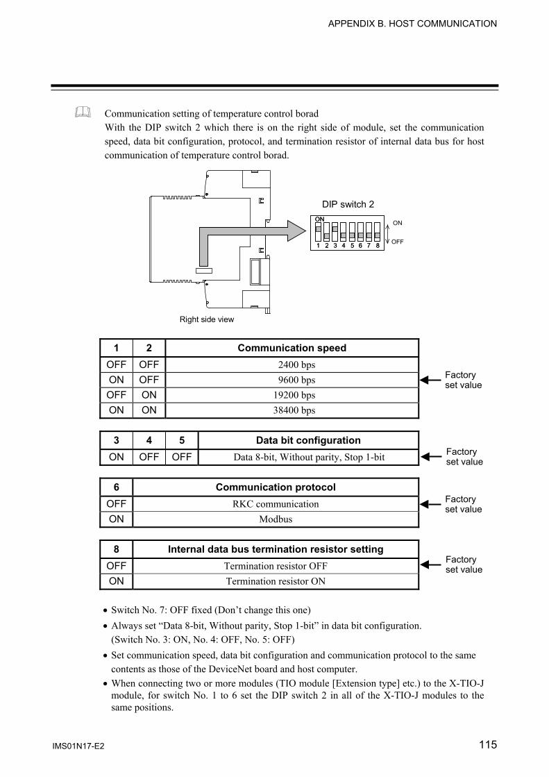
APPENDIX B. HOST COMMUNICATION
IMS01N17-E2 115
Communication setting of temperature control borad With the DIP switch 2 which there is on the right side of module, set the communication speed, data bit configuration, protocol, and termination resistor of internal data bus for host communication of temperature control borad.
1 2 3 4 5 6 7 8
ON
1 2 3 4 5 6 7 8
ON
DIP switch 2
Right side view
ON
OFF
1 2 Communication speed OFF OFF 2400 bps ON OFF 9600 bps OFF ON 19200 bps ON ON 38400 bps
3 4 5 Data bit configuration
ON OFF OFF Data 8-bit, Without parity, Stop 1-bit
6 Communication protocol OFF RKC communication ON Modbus
8 Internal data bus termination resistor setting
OFF Termination resistor OFF ON Termination resistor ON
• Switch No. 7: OFF fixed (Don’t change this one) • Always set “Data 8-bit, Without parity, Stop 1-bit” in data bit configuration.
(Switch No. 3: ON, No. 4: OFF, No. 5: OFF) • Set communication speed, data bit configuration and communication protocol to the same
contents as those of the DeviceNet board and host computer. • When connecting two or more modules (TIO module [Extension type] etc.) to the X-TIO-J
module, for switch No. 1 to 6 set the DIP switch 2 in all of the X-TIO-J modules to the same positions.
Factoryset value
Factoryset value
Factoryset value
Factoryset value

APPENDIX B. HOST COMMUNICATION
IMS01N17-E2 116
B.3 Communication Items List This is a list of data items which can communicate with the DeviceNet board via host communication. • “Identifier” is used for RKC communication. • “Register address” is used for Modbus. • RO: Read only R/W: Read and Write
Register address Name Iden-
tifier HEX DOC Attri-bute Data Facrory
set value
Polling I/O communication Measured data items (IN) ID setting
R8 CH1: 1520 CH2: 1521 CH3: 1522 CH4: 1523 CH5: 1524 CH6: 1525 CH7: 1526 CH8: 1527 CH9: 1528 CH10: 1529
CH1: 5408CH2: 5409CH3: 5410CH4: 5411CH5: 5412CH6: 5413CH7: 5414CH8: 5415CH9: 5416CH10: 5417
R/W 0 to 80 0: No communication data item This is the measured data item (IN) communicating via polling I/O communication. Select any measured data item from among “Controller object (0x64: 64H)” and set the relevant attribute ID. Any CH from 1 to 10 corresponds to any attribute ID from 1 to 10 of object instance 1 in “Controller communication data item setting object (0xC7: C7H).”
For contents of setting items, refer to 6.3 Communication Items List (P. 35).
CH1: 1 CH2 to 10: 0
Polling I/O communication Set data items (OUT) ID setting
R9 CH1: 1540 CH2: 1541 CH3: 1542 CH4: 1543 CH5: 1544 CH6: 1545 CH7: 1546 CH8: 1547 CH9: 1548 CH10: 1549
CH1: 5440CH2: 5441CH3: 5442CH4: 5443CH5: 5444CH6: 5445CH7: 5446CH8: 5447CH9: 5448CH10: 5449
R/W 0 to 80 0: No communication data item This is the set data item (OUT) communicating via polling I/O communication. Select any set data item from among “Controller object (0x64: 64H)” and set the relevant attribute ID. Any CH from 1 to 10 corresponds to any attribute ID from 11 to 20 of object instance 1 in “Controller communication data item setting object (0xC7: C7H).”
For contents of setting items, refer to 6.3 Communication Items List (P. 35).
CH1: 12CH2 to 10: 0
Continued on the next page.

APPENDIX B. HOST COMMUNICATION
IMS01N17-E2 117
Continued from the previous page.
Register addressName Iden-
tifier HEX DOC Attri-bute Data
Facroryset
valuePolling I/O communication Number of communication channels
QY 7D03 32003 R/W 1 to 60 channels This is the number of temperature control channels of the SRX communicating via polling I/O communication. After the data is set, turn off the power once and turn it on again to validate the data. The communication environment can also be set (refer to P. 13) by the rotary switch.
10
X-TIO-J module Error code
ES 7D08 32008 RO Bit data Bit 0: Memory backup error Bit 1: Unused Bit 2: Module configuration error Bit 3 to Bit 15: Unused Data 0: OFF 1: ON [Decimal number: 0 to 3]
⎯
Internal communication Number of connected modules
QN 7D0A 32010 RO 0 to 30 modules 0: When during module recognition with the power turned on This is the number of modules connected to the X-TIO-J module. The TIO board in the X-TIO-J module is also included.
⎯
Internal communication Number of connected TIO channels
QP 7D0B 32011 RO 0 to 60 channels 0: When during module recognition with the power turned on This is the number of TIO channels connected to the X-TIO-J module. The TIO board in the X-TIO-J module is also included.
⎯
Polling I/O communication Number of communication measured data items (IN)
RX 7D0D 32013 R/W 0 to 100 words This is the number of measured data items (IN) (No. of words) communicating via polling I/O communication. After the data is set, turn off the power once and turn it on again to validate the data. The communication environment can also be set (refer to P. 13) by the rotary switch.
0
Continued on the next page.

APPENDIX B. HOST COMMUNICATION
IMS01N17-E2 118
Continued from the previous page.
Register addressName Iden-
tifier HEX DOC Attri-bute Data
Facroryset
valuePolling I/O communication Number of communication set data items (OUT)
RY 7D0E 32014 R/W 0 to 100 words This is the number of set data items (OUT) (No. of words) communicating via polling I/O communication. After the data is set, turn off the power once and turn it on again to validate the data. The communication environment can also be set (refer to P. 13) by the rotary switch.
0
Initial setting mode IN 7D20 32032 R/W 0: Normal setting mode 1: Initial setting mode The instrument cannot be changed to the initial setting mode state at control start (during control).
0
Host communication Transmission transfer time setting
ZX 7D21 32033 R/W 0 to 255 ms Set the wait time until the X-TIO-J module starts sending data after that data is received from the host computer. As this item corresponds to the initial set data, it is readable and writable only in the initial set mode.
255
Modbus Data interval extension time
ZY 7D27 32039 R/W 0 to 255 ms Data time intervals during Modbus communication are extended. As this item corresponds to the initial set data, it is readable and writable only in the initial set mode. After the data is set, turn off the power once and turn it on again to validate the data.
255

IMS01N17-E2 119
APPENDIX C. HARDWARE
C.1 Terminal Configuration Wiring cautions For thermocouple input, use the appropriate compensation wire. For RTD input, use low resistance lead wire with no difference in resistance between the three lead
wires. To avoid noise induction, keep input signal wire away from instrument power line, load lines and power
lines of other electric equipment. If there is electrical noise in the vicinity of the instrument that could affect operation, use a noise filter. • Shorten the distance between the twisted power supply wire pitches to achieve the most effective
noise reduction. • Always install the noise filter on a grounded panel. Minimize the wiring distance between the noise
filter output and the instrument power supply terminals to achieve the most effective noise reduction. • Do not connect fuses or switches to the noise filter output wiring as this will reduce the effectiveness
of the noise filter. Power supply wiring must be twisted and have a low voltage drop. For an instrument with 24 V power supply, supply power from a SELV circuit. A suitable power supply should be considered in end-use equipment. The power supply must be in
compliance with a limited-energy circuits (maximum available current of 8 A). X-TIO-J
CT1
T/R(B)
SG
T/R(A)
RS-485
Host communication CT input Control output 1 Control output 2
15
Relay contact
NO
OUT1
Voltage pulse/ Current/ Voltage OUT1
+ −
5 2
5 2
3 6 7
1617
+ − 24 V DC
Power supply Ground
Thermocouple
TC1 + −
Input channel 1
Voltage/ Current
IN1 + −
RTD
RTD1B
BA
NO
OUT2OUT2+ −
41
41
1013
1014 13
1310
TC2+ −
IN2+ −
912
812
129
RTD2B
B A9
Input channel 2
1918
20
FG
16 15 3 2 1 17 7 6 5 4
20 19 14 13 12 18 11 10 9 8
Upper-side terminal
CT2
Relay contactVoltage pulse/
Current/ Voltage
Lower-side terminal
Thermocouple RTD
Voltage/ Current
Voltage/Current
5.9 mm or ress
3.2 mm or more
Recommended tightening torque: 0.4 N⋅m (4 kgf⋅cm)
Input channel 2 can be used as remote setting input (only for Voltage/Current input). In this case, control output 2 and CT input 2 become unused.
• Terminal No. 11 is not used. • Use the solderless terminals
appropriate to the screw size (M3).• Make sure that the any wiring such
as solderless terminal is not in contact with the adjoining terminals.
Heater break alarm (HBA) functioncannot be used when control output isVoltage/Current output.

APPENDIX C. HARDWARE
IMS01N17-E2 120
C.2 Indication Lamp [Indication Lamp 1] FAIL/RUN
During normal operation: Green lamp: ON (RUN) During error: Red lamp: ON (FAIL)
RX/TX (for host communication using host communication terminals) During data send or receive: Green lamp: ON
EVENT 1 to 4 Display various states by setting. ON state: Green lamp: ON Display contents: Event 1 state, Event 2 state, Comprehensive event state, Output state,
Control state, Execution segment state, Time signal state [Indication Lamp 2] FAIL (for DeviceNet communication)
During error: Red lamp: ON Communication environment setting mode by the switch: Red lamp: flashing
RUN (for DeviceNet communication) During normal operation: Green lamp: ON During memory backup error: Green lamp: slow flashing During module configuration error: Green lamp: slow flashing During communication error: Green lamp: slow flashing During data collection after power ON: Green lamp: rapid flashing
Continued on the next page.
54321
09 8 7
65
54321
09 8 7
65
54
32109
87 6
54
32109
87 6
54
32109
87 6
FAIL/RUNRX/TXEVENT1EVENT2EVENT3EVENT4
Indication Lamp 2
Indication Lamp 1
Temperature control side DeviceNet side
FAIL
RU
NM
S
NS
X-TIO-J module
APPENDIX C. HARDWARE
IMS01N17-E2 121
Continued from the previous page. NS or NET (Network status)
Network is operating normally, but communications have not yet been established: Green lamp: flashing
Network is operating normally (communications established): Green lamp: ON
I/O connection is timeout: Red lamp: flashing A fatal communications error has occurred or Network communications are not possible: Red lamp: ON
MS or MOD (Module status) During normal operation: Green lamp: ON During module configuration error: Green lamp: flashing During memory backup error: Red lamp: ON

APPENDIX C. HARDWARE
IMS01N17-E2 122
C.3 Product Specifications There are data items settable only via host communication in set data items.
For settable items in DeviceNet, refer to the controller object (0x64: 64H) (P. 108). Input
Measuring input: Number of inputs: 2 points (Isolated between each input channel)
Channel 2 can be used as remote input.
Input type: • Voltage (low) input group Thermocouple: K, J, T, S, R, E, B, N (JIS-C1602-1995) PLII (NBS) W5Re/W26Re (ASTM-E988-96) Voltage (low): 0 to 10 mV, 0 to 100 mV, 0 to 1 V
• Resistance temperature detector (RTD) input group (3-wire system) Pt100 (JIS-C1604-1997) JPt100 (JIS-C1604-1989, Pt100 of JIS-C1604-1981)
• Voltage (high)/Current input group Voltage (high): 0 to 5 V, 1 to 5 V, 0 to 10 V Current: 0 to 20 mA, 4 to 20 mA (Input impedance: 250 Ω)
-The type of input needs to be specified when ordering and then fixed. -The type of input can be selected independently for each channel.
Input range: • Temperature input (Thermocouple/RTD input)
Input type Input range K −200 to +1372 °C, −328 to +2502 °F J −200 to +1200 °C, −328 to +2192 °F R −50 to +1768 °C, −58 to +3000 °F S −50 to +1768 °C, −58 to +3000 °F B 0 to 1800 °C, 32 to 3000 °F E −200 to +1000 °C, −328 to +1832 °F N 0 to 1300 °C, 32 to 2372 °F T −200 to +400 °C, −328 to +752 °F
W5Re/W26Re 0 to 2300 °C, 32 to 3000 °F PLII 0 to 1390 °C, 32 to 2534 °F
Pt100 −200 to +850 °C, −328 to +1562 °F JPt100 −200 to +600 °C, −328 to +1112 °F
However, within “Input scale low to Input scale high.”
• Voltage/Current input Programmable range Input scale high: Input scale low to 20000 Input scale low: −20000 to Input scale high However, a input scale span is 20000 or less.

APPENDIX C. HARDWARE
IMS01N17-E2 123
Accuracy (in ambient temperature 23 °C ±2 °C): • Thermocouple input (K, J, T, PLII, E)
Less than −100 °C: ±1.0 °C −100 °C to less than +500 °C: ±0.5 °C 500 °C or more: ± (0.1 % of reading + 1digit) Less than −148 °F: ±1.8 °F −148 °F to less than +932 °F: ±0.9 °F 932 °F or more: ± (0.1 % of reading + 1digit)
• Thermocouple input (R, S, N, W5Re/W26Re) −50 °C to less than +1000 °C: ±1.0 °C 1000 °C or more: ± (0.1 % of reading + 1digit) −58 °F to less than +1832 °F: ±1.8 °F 1832 °F or more: ± (0.1 % of reading + 1digit)
• Thermocouple input (B) Less than 400 °C: ±70.0 °C 400 °C to less than 1000 °C: ±1.0 °C 1000 °C or more: ± (0.1 % of reading + 1digit) Less than 752 °F: ±126.0 °F 752 °F to less than 1832 °F: ±1.8 °F 1832 °F or more: ± (0.1 % of reading + 1digit)
• RTD input Less than 200 °C: ±0.2 °C 200 °C or more: ± (0.1 % of reading + 1digit) Less than 392 °F: ±0.4 °F 392 °F or more: ± (0.1 % of reading + 1digit)
• Voltage/Current input ± 0.1 % of input span
• Cold junction temperature compensation accuracy ±1.0 °C (Ambient temperature 23 °C ±2 °C) Within ±1.5 °C between 0 and 50 °C of ambient temperature ±1.8 °F (Ambient temperature 73.4 °F ±3.6 °F) Within ±2.7 °F between 14 and 122 °F of ambient temperature
Sampling cycle: 25 ms
Input resolution: Thermocouple input: 1 °C or 0.1 °C (1 °F or 0.1 °F) RTD input: 1 °C or 0.1 °C (1 °F or 0.1 °F) Voltage/Current input: 1 to 0.0001 (programmable)
RTD sensor current: Approx. 1 mA
Action at input break: Thermocouple input: Upscale RTD input: Upscale Voltage input 0 to 10 mV, 0 to 100 mV: Upscale 0 to 1 V, 0 to 5 V, 1 to 5 V, 0 to 10 V: Indicate value near 0 V Current input 0 to 20 mA, 4 to 20 mA: Indicate value near 0 mA

APPENDIX C. HARDWARE
IMS01N17-E2 124
Signal source resistance effect: 0.25 μV/Ω (Only for thermocouple input)
Allowable influence of input lead: 10 Ω or less per wire (Only for RTD input)
Input digital filter: First order lag digital filter Time constant: 0.01 to 10.00 seconds (Setting 0.00: Filter OFF)
PV bias: ±Input span
Normal mode rejection ratio (NMRR): 60 dB or more CT input: Number of inputs: 2 points
Sampling cycle: 500 ms (Data update cycle) Resolution of A/D transfer: 10-bit or more Input current: 0.0 to 30.0 A (CTL-6-P-N) 0.0 to 100.0 A (CTL-12-S56-10L-N) Current measuring accuracy: ±5 % of input value or ±2 A (The value whichever is greater)
Output
Number of outputs: 2 points Isolated between input and output and between output and power supply. Not isolated between each output channel.
Output type: The type of output needs to be specified when ordering and then fixed. (The type of output can be selected independently for each channel.) • Relay contact output
Contact type: 1a contact 250 V AC 3 A (Resistive load) Electrical life: 300,000 times or more (Rated load)
• Voltage pulse output Output voltage: 0/12 V DC Allowable load resistance: 600 Ω or more
• Current output Output type: 0 to 20 mA DC, 4 to 20 mA DC Allowable load resistance: 600 Ω or less Output resolution: 11-bit or more
• Voltage output Output voltage: 0 to 5 V DC, 1 to 5 V DC, 0 to 10 V DC Allowable load resistance: 1 kΩ or more Output resolution: 11-bit or more

APPENDIX C. HARDWARE
IMS01N17-E2 125
Indication lamp Number of indicates: 10 points
Indication contents: Temperature control side • Operation state indication [RUN/FAIL] (1 point)
During normal operation: Green lamp: ON (RUN) During error: Red lamp: ON (FAIL)
• Communication state indication [RX/TX] (1 point) During data send or receive: Green lamp: ON
• Event display [EVENT1 to 4] (4 points) Various states are displayed depending on setting. Display contents: Event 1 state, Event 2 state, Comprehensive
event state, Output state, Control state, Execution segment state, Time signal state
DeviceNet communication side • Operation state indication [RUN, FAIL] (2 points)
During normal operation: Green lamp: ON (RUN) During error: Red lamp: ON (FAIL) During data collection after power ON: Green lamp: rapid flashing (RUN) During self-diagnostic error: Green lamp: slow flashing (RUN) During communication environment setting mode: Red lamp: slow flashing (FAIL)
• NS or NET (Network status) Network is operating normally, but communications have not yet been established: Green lamp: flashing Network is operating normally (communications established):
Green lamp: ON I/O connection is timeout: Red lamp: flashing A fatal communications error has occurred or Network communications are not possible: Red lamp: ON
• MS or MOD (Module status) During normal operation: Green lamp: ON During module configuration error: Green lamp: flashing During memory backup error: Red lamp: ON
Setting
Setting method: Setting by communication
Setting range: Same as input range
Setting resolution: Same as input resolution

APPENDIX C. HARDWARE
IMS01N17-E2 126
Control Number of controls: 2 points
Control method: Brilliant PID control - Correspond to the direct action and the reverse action. - Do not support the heat/cool control.
Additional functions: Autotuning function Output limiter function Output change rate limiter
Setting range: Proportional band: Temperature input: 0 (0.0) to Input span Voltage/Current input: 0.0 to 1000.0 % of Input span (0 or 0.0: ON/OFF action) Integral time: 0.01 to 360.00 seconds or 0.1 to 3600.0 seconds (Selectable) Derivative time: 0.00 to 360.00 seconds or 0.0 to 3600.0 seconds (Selectable) (0.00 or 0.0: PI action)
Control response parameter: Slow, Medium, Fast
Output limiter high: −5.0 to +105.0 %
Output limiter low: −5.0 to +105.0 %
Output change rate limiter: 0.0 to 100.0 %/second
Proportioning cycle time: 0.2 to 50.0 seconds
Direct/Reverse action selection: Direct action, Reverse action
Hot/Cold start selection: Hot 1, Hot 2, Cold 1, Cold 2
AUTO/MAN selection: Auto mode (AUTO), Manual mode (MAN)
Manual output setting: −5.0 to +105.0 % However, the actual output value is within output limiter range.
Start determination point: 0 to Input span
PID/AT transfer: PID control, Autotuning (AT)
AT bias: ±Input span
Remote/Local transfer: Local mode, Remote mode
Setting method of PID constants: Level PID
Eight types of PID parameters are selectable depending on level PID high limit setting positions. Setting range of Level 1to 8: Same as input range Level 1≤ Level 2≤ Level 3≤ ・・・・・・・ ≤ Level 7≤ Level 8 (Set of level 8 is fixed with input scale high.)

APPENDIX C. HARDWARE
IMS01N17-E2 127
Event function Number of events: 2 points/channel
Event type: Deviation high, Deviation low, Deviation high/low, Band, Process high, Process low
Additional function: Hold action, Re-hold action Number of event delay times: 0 to 255 times
Setting range: Deviation high, Deviation low: −Input span to +Input span Deviation high/low, Band: 0 to Input span Process high, Process low: Same as input range
Differential gap: 0 to Input span
Event state: Output the event state as communication data. Heater break alarm (HBA) function
Number of HBA: 2 points
Setting range: 0.0 to 30.0 A (Current transformer: CTL-6-P-N) 0.0 to 100.0 A (Current transformer: CTL-12-S56-10L-N) (0.0 A: HBA OFF)
Additional function: Number of event delay times: 1 to 255 times
HBA state: Output the HBA state as communication data. Control loop break alarm (LBA) function
Number of LBA: 2 points
LBA time: 1 to 7200 seconds
LBA deadband (LBD) setting: 0 to Input span
LBA state: Output the LBA state as communication data. Comprehensive event state
Event state: Bit data items are expressed in decimal number from 0 to 31. Burnout: Bit 0 Event 1 state: Bit 1 Event 2 state: Bit 2 Heater break alarm (HBA) state: Bit 3 Control loop break alarm (LBA) state: Bit 4

APPENDIX C. HARDWARE
IMS01N17-E2 128
Program control Program setting: Level setting (Setting of each channel)
Segment time (Setting of each channel)
Setting range: Level: Same as main set value Segment time: 0.00 to 300.00 seconds (factory set value) 0.0 to 3000.0 seconds 0 to 30000 seconds 0 to 30000 minutes Either transfer is possible.
Number of program execution times: 1 to 1000 times (1000 times: Program executes an infinite number of times.)
Time accuracy: ± (0.01 % of Reading + 1digit)
Number of patterns: Up to 16 patterns (Up to 16 segments/pattern) Pattern link function provided
Number of segments: Up to 256 segments (16 patterns × 16 segments)
Program operation start mode: Zero start PV start 1 (Fixed time type) PV start 2 (Time shortening type)
Hold function: • The program stops its progress temporarily. • This function becomes valid during program operation. • The hold status is not released if set to any of other program
operation modes (FIX or MAN).
Step function: • The program progress by one segment. (One segment progresses by the setting per one.) • This function becomes valid during program operation. • The step action cannot be used in the hold state.
Wait function: This is the function the program stops to wait for moving to the next segment when a measured value is difficult to follow the progress of the program. Setting range of wait zone: 0 to Input span
(Setting 0: Wait function OFF) • Wait zone is setting for each pattern • Can confirm wait status with communication
Pattern end output: Number of outputs: 2 points Pattern end output time:
0.00 to 300.00 seconds or 0.00 to 300.00 minutes When 0 is set, the pattern end output is not turned off.
Output reset: The output can be turned off by changing to the reset state.
Continued on the next page.

APPENDIX C. HARDWARE
IMS01N17-E2 129
Continued from the previous page.
• When program is repeated: Output turned on for about 0.5 seconds • When programs are linked: To be turned on final pattern • The pattern end output is turned off when fixed set point (FIX) or
manual (MAN) control is performed, but the pattern end output state returns to the original state if returned to the program control state.
Program operation mode: • Reset mode (RESET state) Stop control and return the segment number to No. 1. Turn off the time signal output and the end output. An event becomes OFF. A set value becomes 0.
• Program control mode (RUN state) Execute program control.
• Fixed set point control mode (FIX state) Execute fixed set point.
• Manual control mode (MAN state) Manual control can be performed.
Time signal output: Number of settings: 16 (per pattern) Time signal ON segment: 1 to 16 Time signal ON time: The time setting unit is the same as the
segment time setting unit. Time signal OFF segment: 1 to 16
(However, it needs to be the same as the start segment or larger.)
Time signal OFF time: The time setting unit is the same as the segment time setting unit.
• Always make the setting as follows. “ON segment/ON time < OFF segment/OFF time” If the above inequality is not satisfied, no time signal is output.
• If the ON and OFF time are set larger than the segment time, become the same time as the segment time.
• When no time signal is used, set the same “ON segment/ON time” and “OFF segment/OFF rime.” In this case, no time signal is output.
• The time signal output state is held in the wait or hold state. • The pattern end output is turned off when fixed set point (FIX) or
manual (MAN) control is performed, but the time signal output state returns to the original state if returned to the program control state.
• The time signal output is turned off when the autotuning (AT) function is activated.

APPENDIX C. HARDWARE
IMS01N17-E2 130
Control action selection function at input error Function: This function is used to change to the manual mode when the input is
abnormal [Input error determination point (low) ≥ PV or PV ≥ Input error determination point (high)] in the control state.
Action selection: It is selected whether or not the manual output is changed independently of the high limit and low limit.
Setting range: Input error determination point (high): Within input scale range Input error determination point (low): Within input scale range Manipulated output value at input error: −5.0 to +105.0 %
(However, the actual output value is within output limiter range.) Control RUN/STOP function
Function: RUN/STOP action is taken simultaneously for two channels. The function and output in the control stop state are the same as those when the power supply is turned off. Control STOP: 0 Control RUN: 1
Self-diagnostic function
Check item (error code): Memory backup error Module configuration error If any error occurs, Bit 7 of attribute ID: 5 in Identity object (0x01) is set to 1.
General specifications
Power supply: Power supply voltage: 24 V DC Power supply voltage range: 21.6 to 26.4 V DC Current consumption: 200 mA or less/module
Insulation resistance: 20 MΩ or more at 500 V DC (Between each insulation block)
Withstand voltage: 600 V AC for one minute (Between each insulation block)
Power failure effect: No influence even under power failure of 20 ms or less.
Data backup: Data backed up by EEPROM. Number of write times: 1 million times or more Data storage period: Approx. 10 years
Working environment conditions: Allowable ambient temperature: −10 to +50 °C Allowable ambient humidity: 5 to 95 %RH (Non condensing) Absolute humidity: MAX.W.C 29 g/m3 dry air at 101.3 kPa Installation environment conditions: Indoor use Altitude up to 2000 m

APPENDIX C. HARDWARE
IMS01N17-E2 131
Mounting and structure Mounting procedure: DIN rail mounting
Case color: Terminal base: Black Module mainframe: Bluish white
Dimensions: 40.5 (W) ×125.0 (H) ×110.0 (D) mm
Weight: Open-style connector type: Approx. 270 g Micro-style connector type: Approx. 290 g
Standard
Safety standard: UL: UL61010A-1 CSA: CAN/CSA-C22.2 No1010.1
CE marking: LVD: EN61010-1 OVERVOLTAGE CATEGORYII, POLLUTION DEGREE 2, Class II (Reinforced insulation) EMC: EN61326-1
C-Tick: EN55011

132 IMS01N17-E2
MEMO

The first edition: NOV. 2004 [IMQ00]The second edition: JAN. 2011 [IMQ00]

IMS01P17-E2 JAN. 2011
RKC INSTRUMENT INC.
HEADQUARTERS: 16-6, KUGAHARA 5-CHOME, OHTA-KU TOKYO 146-8515 JAPAN PHONE: 03-3751-9799 (+81 3 3751 9799) E-mail: [email protected] FAX: 03-3751-8585 (+81 3 3751 8585)
R
Related Documents


![SRZ Instruction Manual [For PLC Communicatio] - RKC …€¦ · · 2015-12-21RKC INSTRUMENT INC. IMS01T13-E3 ® SRZ Instruction Manual [For PLC Communication] Module Type Controller](https://static.cupdf.com/doc/110x72/5ade87487f8b9aa5088e4944/srz-instruction-manual-for-plc-communicatio-rkc-2015-12-21rkc-instrument.jpg)


![SRZ Instruction Manual [For PLC Communication] - rkc instrument inc](https://static.cupdf.com/doc/110x72/620aed76a0970e59cd732db4/srz-instruction-manual-for-plc-communication-rkc-instrument-inc.jpg)
