Glenn Research Center at Lewis Field Development of a High Specific Energy Flywheel Module, and Studies to Quantify Its Mission Applications and Benefits Tim Dever / NASA GRC https://ntrs.nasa.gov/search.jsp?R=20150009522 2020-01-01T23:08:29+00:00Z

Welcome message from author
This document is posted to help you gain knowledge. Please leave a comment to let me know what you think about it! Share it to your friends and learn new things together.
Transcript
Glenn Research Center at Lewis Field
Development of a High Specific Energy Flywheel Module,
and Studies to Quantify Its Mission Applications and Benefits
Tim Dever / NASA GRC
https://ntrs.nasa.gov/search.jsp?R=20150009522 2020-01-01T23:08:29+00:00Z
Glenn Research Center at Lewis Field 2
Topics
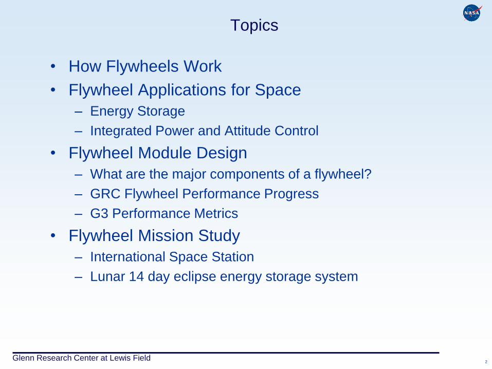
• How Flywheels Work
• Flywheel Applications for Space
– Energy Storage
– Integrated Power and Attitude Control
• Flywheel Module Design
– What are the major components of a flywheel?
– GRC Flywheel Performance Progress
– G3 Performance Metrics
• Flywheel Mission Study
– International Space Station
– Lunar 14 day eclipse energy storage system
Glenn Research Center at Lewis Field
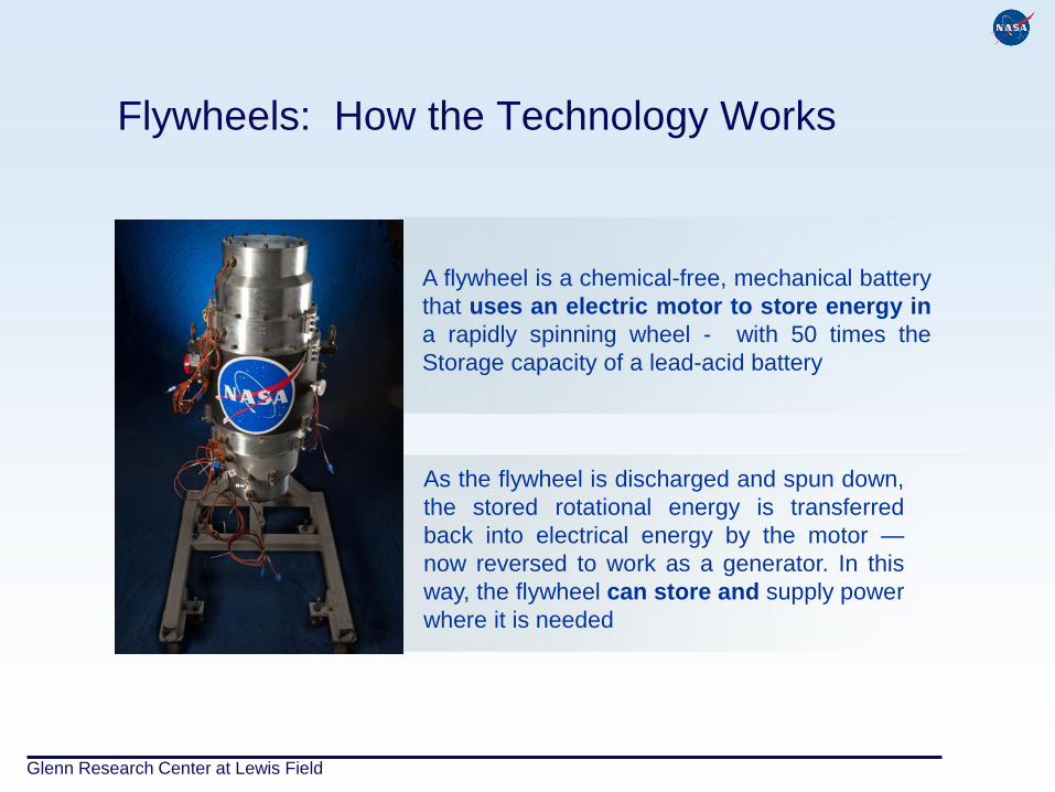
Flywheels: How the Technology Works
A flywheel is a chemical-free, mechanical battery
that uses an electric motor to store energy in
a rapidly spinning wheel - with 50 times the
Storage capacity of a lead-acid battery
As the flywheel is discharged and spun down,
the stored rotational energy is transferred
back into electrical energy by the motor —
now reversed to work as a generator. In this
way, the flywheel can store and supply power
where it is needed
Glenn Research Center at Lewis Field
Flywheel Applications For Space
Glenn Research Center at Lewis Field 5
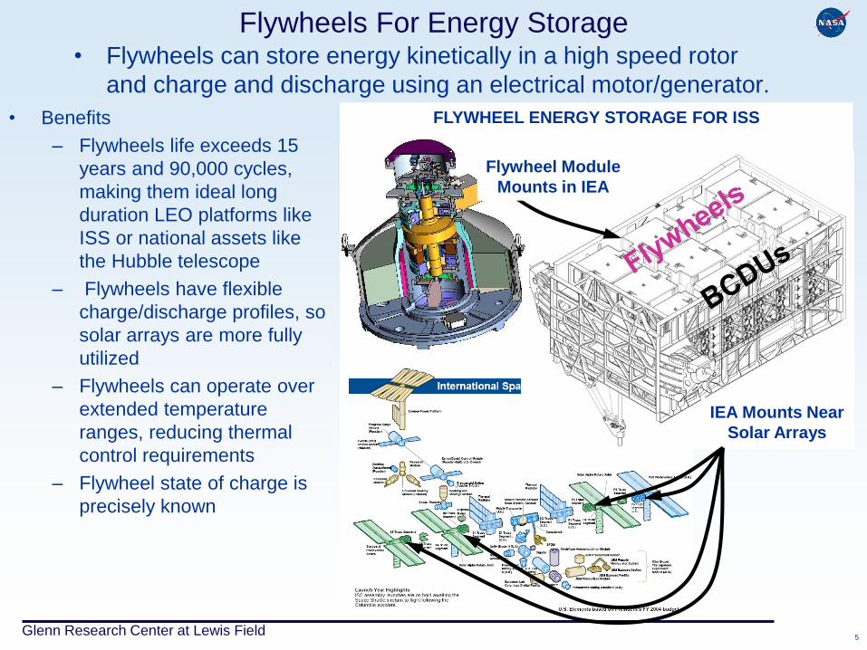
FLYWHEEL ENERGY STORAGE FOR ISS
Flywheels For Energy Storage • Flywheels can store energy kinetically in a high speed rotor
and charge and discharge using an electrical motor/generator.
IEA Mounts Near
Solar Arrays
• Benefits
– Flywheels life exceeds 15
years and 90,000 cycles,
making them ideal long
duration LEO platforms like
ISS or national assets like
the Hubble telescope
– Flywheels have flexible
charge/discharge profiles, so
solar arrays are more fully
utilized
– Flywheels can operate over
extended temperature
ranges, reducing thermal
control requirements
– Flywheel state of charge is
precisely known
Flywheel Module
Mounts in IEA
Glenn Research Center at Lewis Field 6
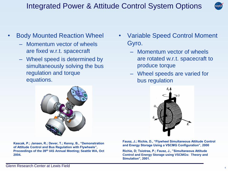
Integrated Power & Attitude Control System Options
• Body Mounted Reaction Wheel
– Momentum vector of wheels
are fixed w.r.t. spacecraft
– Wheel speed is determined by
simultaneously solving the bus
regulation and torque
equations.
• Variable Speed Control Moment
Gyro.
– Momentum vector of wheels
are rotated w.r.t. spacecraft to
produce torque
– Wheel speeds are varied for
bus regulation
Fausz, J.; Richie, D., “Flywheel Simultaneous Attitude Control
and Energy Storage Using a VSCMG Configuration”, 2000
Richie, D; Tsiotras, P.; Fausz, J., ”Simultaneous Attitude
Control and Energy Storage using VSCMGs: Theory and
Simulation”, 2001.
Kascak, P.; Jansen, R.; Dever, T.; Kenny, B., “Demonstration
of Attitude Control and Bus Regulation with Flywheels”,
Proceedings of the 39th IAS Annual Meeting; Seattle WA, Oct
2004.
Glenn Research Center at Lewis Field
Flywheel Module Design
Glenn Research Center at Lewis Field 8
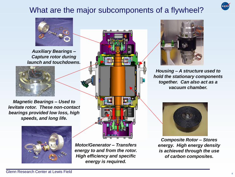
What are the major subcomponents of a flywheel?
Auxiliary Bearings –
Capture rotor during
launch and touchdowns.
Magnetic Bearings – Used to
levitate rotor. These non-contact
bearings provided low loss, high
speeds, and long life.
Housing – A structure used to
hold the stationary components
together. Can also act as a
vacuum chamber.
Composite Rotor – Stores
energy. High energy density
is achieved through the use
of carbon composites.
Motor/Generator – Transfers
energy to and from the rotor.
High efficiency and specific
energy is required.
Glenn Research Center at Lewis Field 9
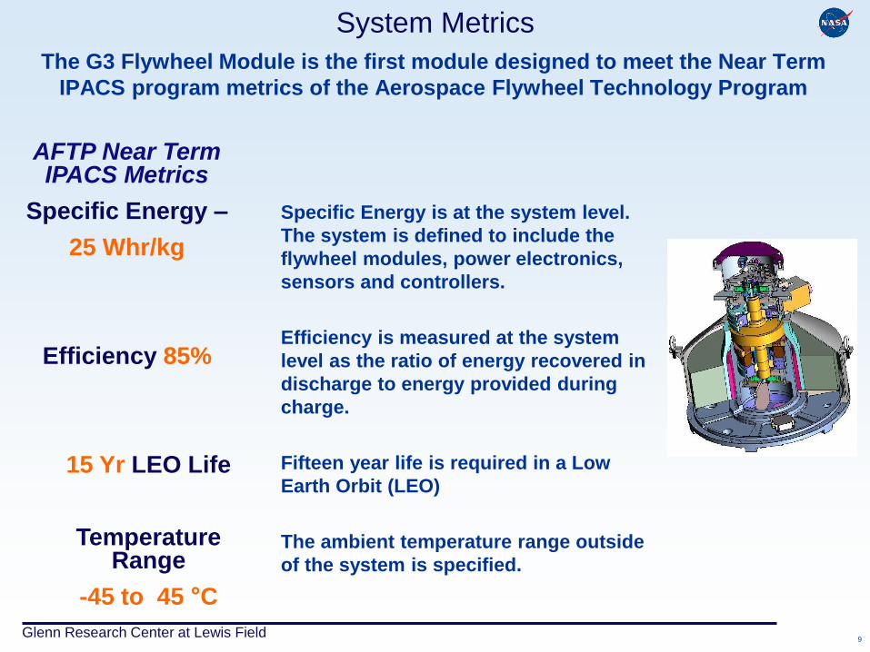
System Metrics
The G3 Flywheel Module is the first module designed to meet the Near Term
IPACS program metrics of the Aerospace Flywheel Technology Program
AFTP Near Term IPACS Metrics
Specific Energy –
25 Whr/kg
Efficiency 85%
15 Yr LEO Life
Temperature Range
-45 to 45 °C
Specific Energy is at the system level.
The system is defined to include the
flywheel modules, power electronics,
sensors and controllers.
Efficiency is measured at the system
level as the ratio of energy recovered in
discharge to energy provided during
charge.
Fifteen year life is required in a Low
Earth Orbit (LEO)
The ambient temperature range outside
of the system is specified.
Glenn Research Center at Lewis Field 10
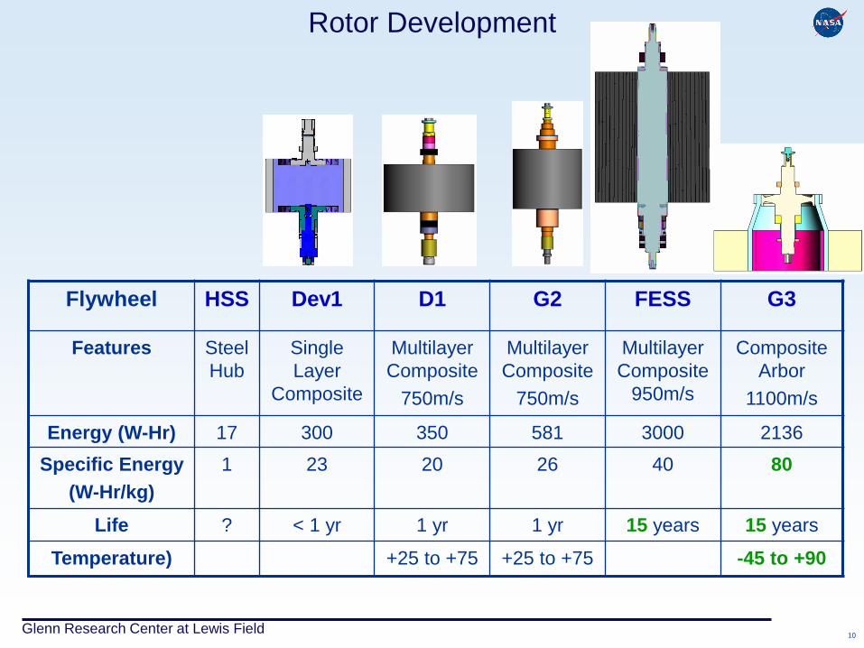
Rotor Development
Flywheel HSS Dev1 D1 G2 FESS G3
Features Steel
Hub
Single
Layer
Composite
Multilayer
Composite
750m/s
Multilayer
Composite
750m/s
Multilayer
Composite
950m/s
Composite
Arbor
1100m/s
Energy (W-Hr) 17 300 350 581 3000 2136
Specific Energy
(W-Hr/kg)
1 23 20 26 40 80
Life ? < 1 yr 1 yr 1 yr 15 years 15 years
Temperature) +25 to +75 +25 to +75 -45 to +90
Glenn Research Center at Lewis Field 11
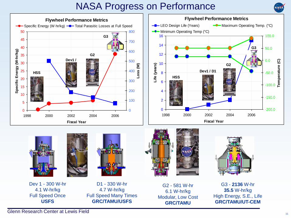
NASA Progress on Performance
Flywheel Performance Metrics
0
5
10
15
20
25
30
35
40
45
50
1998 2000 2002 2004 2006
Fiscal Year
Sp
ecif
ic E
nerg
y (
W-h
r/kg
)
0
100
200
300
400
500
600
700
800
Lo
ss (
W)
Specific Energy (W·hr/kg) Total Parasitic Losses at Full Speed
HSS
Dev1 /
G2
G3
Flywheel Performance Metrics
0
2
4
6
8
10
12
14
16
1998 2000 2002 2004 2006
Fiscal Year
Lif
e (
years
)
-200.0
-150.0
-100.0
-50.0
0.0
50.0
100.0
Tem
pera
ture
(C
)
LEO Design Life (Years) Maximum Operating Temp. (°C)
Minimum Operating Temp (°C)
HSS
Dev1 / D1
G2
G3
Dev 1 - 300 W-hr
4.1 W-hr/kg
Full Speed Once
USFS
D1 - 330 W-hr
4.7 W-hr/kg
Full Speed Many Times
GRC/TAMU/USFS
G2 - 581 W-hr
6.1 W-hr/kg
Modular, Low Cost
GRC/TAMU
G3 - 2136 W-hr
35.5 W-hr/kg
High Energy, S.E., Life
GRC/TAMU/UT-CEM
Glenn Research Center at Lewis Field
Flywheel Mission Study
Glenn Research Center at Lewis Field 13
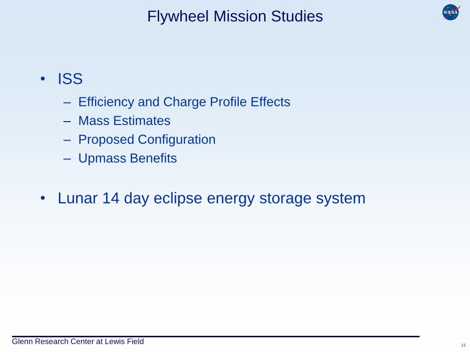
Flywheel Mission Studies
• ISS
– Efficiency and Charge Profile Effects
– Mass Estimates
– Proposed Configuration
– Upmass Benefits
• Lunar 14 day eclipse energy storage system
Glenn Research Center at Lewis Field 14
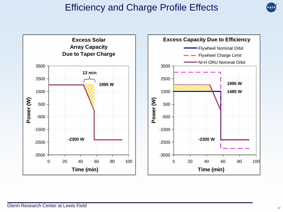
Efficiency and Charge Profile Effects
Excess Solar
Array Capacity
Due to Taper Charge
-3500
-2500
-1500
-500
500
1500
2500
3500
0 20 40 60 80 100
Time (min)
Po
we
r (W
)
1995 W
-2300 W
13 min
Excess Capacity Due to Efficiency
-3500
-2500
-1500
-500
500
1500
2500
3500
0 20 40 60 80 100
Time (min)
Po
we
r (W
)
Flywheel Nominal Orbit
Flywheel Charge Limit
Ni-H ORU Nominal Orbit
1485 W
-2300 W
1995 W
Glenn Research Center at Lewis Field 15
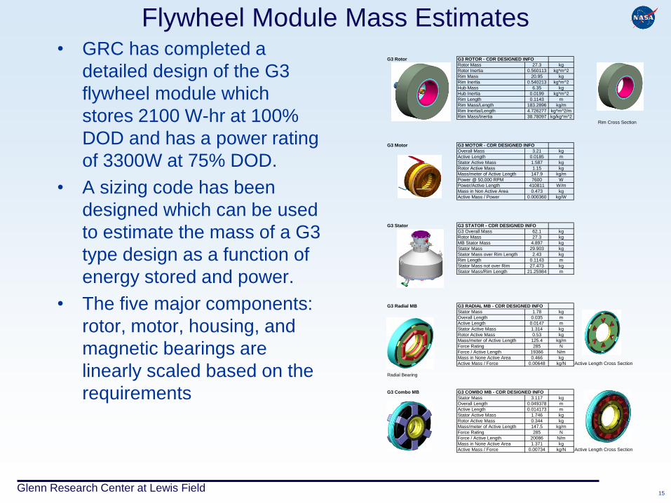
Flywheel Module Mass Estimates • GRC has completed a
detailed design of the G3
flywheel module which
stores 2100 W-hr at 100%
DOD and has a power rating
of 3300W at 75% DOD.
• A sizing code has been
designed which can be used
to estimate the mass of a G3
type design as a function of
energy stored and power.
• The five major components:
rotor, motor, housing, and
magnetic bearings are
linearly scaled based on the
requirements
G3 Rotor G3 ROTOR - CDR DESIGNED INFO
Rotor Mass 27.3 kg
Rotor Inertia 0.560113 kg*m^2
Rim Mass 20.95 kg
Rim Inertia 0.540213 kg*m^2
Hub Mass 6.35 kg
Hub Inertia 0.0199 kg*m^2
Rim Length 0.1143 m
Rim Mass/Length 183.2896 kg/m
Rim Inertia/Length 4.726277 kg*m^2/m
Rim Mass/Inertia 38.78097 kg/kg*m^2
Rim Cross Section
G3 Motor G3 MOTOR - CDR DESIGNED INFO
Overall Mass 3.21 kg
Active Length 0.0185 m
Stator Active Mass 1.587 kg
Rotor Active Mass 1.15 kg
Mass/meter of Active Length 147.9 kg/m
Power @ 50,000 RPM 7600 W
Power/Active Length 410811 W/m
Mass in Non Active Area 0.473 kg
Active Mass / Power 0.000360 kg/W
G3 Stator G3 STATOR - CDR DESIGNED INFO
G3 Overall Mass 62.1 kg
Rotor Mass 27.3 kg
MB Stator Mass 4.897 kg
Stator Mass 29.903 kg
Stator Mass over Rim Length 2.43 kg
Rim Length 0.1143 m
Stator Mass not over Rim 27.473 kg
Stator Mass/Rim Length 21.25984 m
G3 Radial MB G3 RADIAL MB - CDR DESIGNED INFO
Stator Mass 1.78 kg
Overall Length 0.035 m
Active Length 0.0147 m
Stator Active Mass 1.314 kg
Rotor Active Mass 0.53 kg
Mass/meter of Active Length 125.4 kg/m
Force Rating 285 N
Force / Active Length 19366 N/m
Mass in None Active Area 0.466 kg
Active Mass / Force 0.00648 kg/N Active Length Cross Section
Radial Bearing
G3 Combo MB G3 COMBO MB - CDR DESIGNED INFO
Stator Mass 3.117 kg
Overall Length 0.049378 m
Active Length 0.014173 m
Stator Active Mass 1.746 kg
Rotor Active Mass 0.344 kg
Mass/meter of Active Length 147.5 kg/m
Force Rating 285 N
Force / Active Length 20086 N/m
Mass in None Active Area 1.371 kg
Active Mass / Force 0.00734 kg/N Active Length Cross Section
Glenn Research Center at Lewis Field 16
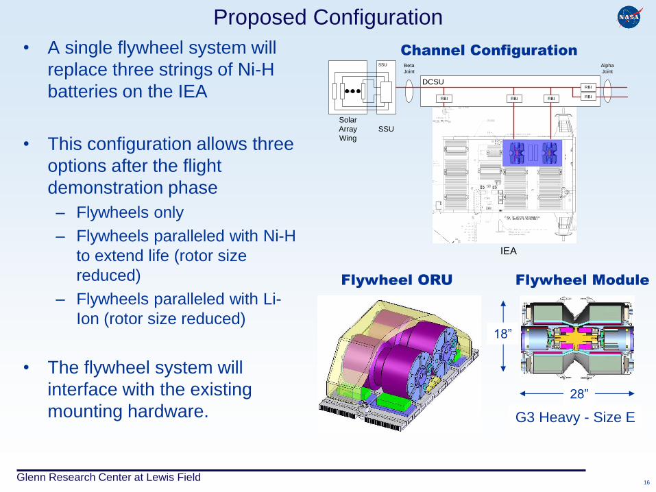
Proposed Configuration
• A single flywheel system will
replace three strings of Ni-H
batteries on the IEA
• This configuration allows three
options after the flight
demonstration phase
– Flywheels only
– Flywheels paralleled with Ni-H
to extend life (rotor size
reduced)
– Flywheels paralleled with Li-
Ion (rotor size reduced)
• The flywheel system will
interface with the existing
mounting hardware.
Channel Configuration
Flywheel ORU
DCSU
SSU
RBI
RBI
Beta
Joint
Alpha
Joint
RBIRBI RBI
Solar
Array
Wing
SSU
IEA
18”
G3 Heavy - Size E
28”
Flywheel Module
Glenn Research Center at Lewis Field 17
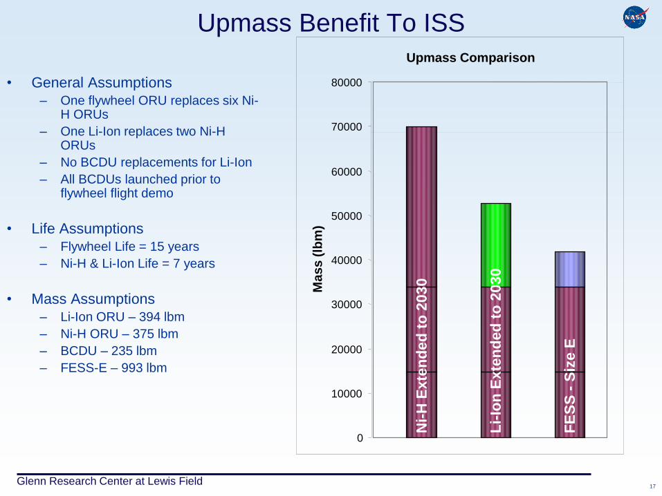
Upmass Benefit To ISS
• General Assumptions
– One flywheel ORU replaces six Ni-H ORUs
– One Li-Ion replaces two Ni-H ORUs
– No BCDU replacements for Li-Ion
– All BCDUs launched prior to flywheel flight demo
• Life Assumptions
– Flywheel Life = 15 years
– Ni-H & Li-Ion Life = 7 years
• Mass Assumptions
– Li-Ion ORU – 394 lbm
– Ni-H ORU – 375 lbm
– BCDU – 235 lbm
– FESS-E – 993 lbm
Upmass Comparison
Ni-
H E
xte
nd
ed
to
2030
Li-
Ion
Exte
nd
ed
to
2030
FE
SS
- S
ize E
0
10000
20000
30000
40000
50000
60000
70000
80000
Ma
ss
(lb
m)
Glenn Research Center at Lewis Field 18
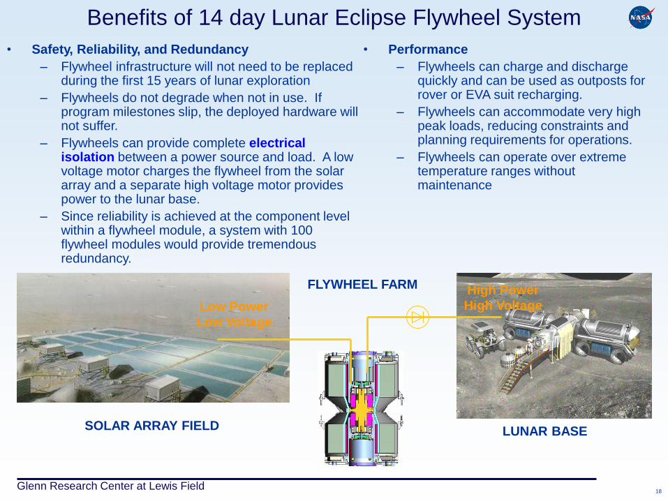
Benefits of 14 day Lunar Eclipse Flywheel System
• Safety, Reliability, and Redundancy
– Flywheel infrastructure will not need to be replaced during the first 15 years of lunar exploration
– Flywheels do not degrade when not in use. If program milestones slip, the deployed hardware will not suffer.
– Flywheels can provide complete electrical isolation between a power source and load. A low voltage motor charges the flywheel from the solar array and a separate high voltage motor provides power to the lunar base.
– Since reliability is achieved at the component level within a flywheel module, a system with 100 flywheel modules would provide tremendous redundancy.
• Performance
– Flywheels can charge and discharge quickly and can be used as outposts for rover or EVA suit recharging.
– Flywheels can accommodate very high peak loads, reducing constraints and planning requirements for operations.
– Flywheels can operate over extreme temperature ranges without maintenance
SOLAR ARRAY FIELD LUNAR BASE
Low Power
Low Voltage
High Power
High Voltage
FLYWHEEL FARM
Glenn Research Center at Lewis Field 19
Summary
• Flywheels have been experimentally shown to
provide bus regulation and attitude control capability
in a laboratory.
• The G3 flywheel can provide 25W-hr/kg system
specific energy, 85% round trip efficiency for a 15
year, LEO application
• A sizing code based on the G3 flywheel technology
level was used to evaluate flywheel technology for
ISS energy storage, ISS reboost, and Lunar Energy
Storage with favorable results.
Related Documents