Faculty of Engineering Technology INCORPORATING FLYWHEEL HYBRID MODULE IN MOTORCYCLE: SIMULATION AND ANALYSIS APPROACH MUHAMMAD HAZIQ BIN AZIZ B071310631 Bachelor of Mechanical Engineering Technology (Automotive Technology) with Honours 2016

Welcome message from author
This document is posted to help you gain knowledge. Please leave a comment to let me know what you think about it! Share it to your friends and learn new things together.
Transcript

Faculty of Engineering Technology
INCORPORATING FLYWHEEL HYBRID MODULE IN MOTORCYCLE:
SIMULATION AND ANALYSIS APPROACH
MUHAMMAD HAZIQ BIN AZIZ B071310631
Bachelor of Mechanical Engineering Technology (Automotive Technology) with Honours
2016
INCORPORATING FLYWHEEL HYBRID MODULE IN MOTORCYCLE:
S IMULATION AND ANALYS IS APPROACH
MUHAMMAD HAZIQ BIN AZIZ B071310631
940331-01-5187
This report submitted in accordance with requirement of the Universiti Teknikal Malaysia Melaka (UTeM) for the Bachelor of Mechanical Engineering Technology
(Automotive Technology) (Hons.)
Faculty of Engineering Technology
UNIVERS ITI TEKNIKAL MALAYS IA MELAKA
2016

DECLARATION
I declare that this thesis entitled “Incorporating Flywheel Hybrid Module In Motorcycle
Simulation And Analysis Approach” is the result of my own research except as cited in the
references. The thesis has not been accepted for any degree and is not concurrently submitted
in candidature of any other degree.
Signature : ...........................................
Name : ...........................................
Date : ............................................

APPROVAL
I hereby declare that I have read this report and in my opinion this report is sufficient in
terms of scope and quality as a partial fulfillment of Bachelor of Mechanical Engineering
Technology (Automotive Technology) (Hons.).
Signature :…….........................……….
Supervisor Name :……………………...........…
Date :……………………................

DEDICATION
I would like to thanks to everyone who involved in finishing my final year project.
First of all I would like to say thank you to my project supervisor En. Muhammad Zaidan
Bin Abdul Manaf for the guidance and teaching while finishing this project. All of those
teaching and effort were priceless to me.
I would also like to thank my family who keep supporting morally all the way in
completing this project.
Specials thanks to my friend that has help me in completing this final year project and
several UTeM staff that giving the support and help.
Finally, I would like to thanks to the researcher who publish their research paper which is
my main source in completing this final year project.

i
ABS TRACT
This study investigates the simulation and analysis the structure and material of Flywheel
Hybrid Module (FHM) in order to get good performance during the operation. Simulation
and Analysis Phase is done to reduce the time and cost consume to run a prototype if using
experimental method. Besides, this phase is also to show and demonstrate the eventual real
effects and condition of the FHM over time. The simulation and analysis of the FHM is done
by Hyper Work Inspire Solid Thinking 2016. The design of the FHM is divided into two
main parts which are flywheel and rim. The design of the FHM is follow the correct
parameters suggest by the embodiment design phase. In the simulation, angular velocity is
applied based on the safety factor consideration and the speed limit of FHM in the real life.
The simulation start with initial velocity of 1000 rpm until the maximum velocity of 9000
rpm which is considered the standard speed of a motorcycle in real life. Two material are be
tested in this phase which are medium carbon steel and aluminum. As result, Von Mises
stress and displacement for every material is analyzed. For aluminum flywheel, the
maximum stress and displacement are 154.5 MPa and 0.395 mm while for aluminum rim,
the maximum stress and displacement are 1176.0 MPa and 0.699 mm. Centrifugal force also
be determined and analyzed for each of velocity applied in the simulation. For aluminum
flywheel and rim, the maximum centrifugal force are 94.67 rad m kg/s2 and 258.05 rad m
kg/s2. The stress and displacement data can be used to determine the high stress
concentration. From the high stress concentration, the fatigue area can be determine and
fatigue of the FHM can be predict well. Lastly, the structure and material of the FHM is
determined and the best material for FHM is aluminum in order to achieve good
performance.

ii
ABS TRAK
Kajian ini menyiasat simulasi dan analisis struktur dan bahan “Flywheel Hybrid Modul
(FHM)” untuk mendapatkan prestasi yang baik semasa operasi. Simulasi dan fasa analisis
dilakukan untuk mengurangkan masa dan kos untuk menjalankan sebuah prototaip jika
menggunakan kaedah eksperimen. Selain itu, fasa ini juga adalah untuk memaparkan dan
menunjukkan kesan sebenar dan keadaan FHM itu dari semasa ke semasa. Simulasi dan
analisis FHM itu dilakukan dengan “Hyper Work Solid Thinking 2016”. Reka bentuk FHM
itu terbahagi kepada dua bahagian utama iaitu flywheel dan rim. Reka bentuk FHM itu
adalah parameter yang betul dicadangkan oleh fasa Reka Bentuk. Dalam simulasi, halaju
sudut digunakan berdasarkan pertimbangan faktor keselamatan dan had laju FHM dalam
kehidupan sebenar. Simulasi di mulakan dengan halaju awal 1000 rpm sehingga halaju
maksimum 9000 rpm yang dianggap standard kelajuan motosikal dalam kehidupan sebenar.
Dua bahan akan diuji dalam fasa ini iaitu sederhana karbon keluli dan aluminium. Sebagai
hasil, Von Mises tekanan dan anjakan untuk setiap bahan dianalisis. Bagi flywheel
aluminium, tekanan maksimum dan anjakan adalah 154.5 MPa dan 0.395 mm manakala
untuk aluminium rim, tekanan maksimum dan anjakan adalah 1176.0 MPa 0.699 mm.
Emparan juga boleh ditentukan dan dianalisa untuk setiap halaju yang digunakan dalam
simulasi tersebut. Bagi flywheel aluminium dan rim, emparan yang maksimum adalah 94.67
rad m kg/s2 dan 258.05 rad m kg/s2. Data tekanan dan anjakan boleh digunakan untuk
menentukan kepekatan tinggi tekanan. Dari kepekatan tinggi tekanan, kawasan keletihan ini
boleh menentukan dan keletihan FHM itu boleh diramal dengan baik. Akhir sekali, struktur
dan bahan FHM yang ditentukan dan bahan terbaik untuk FHM adalah aluminium untuk
mencapai prestasi yang baik.

iii
ACKNOWLEDGEMENTS
First and foremost, I would like to take this opportunity to express my sincere acknowledgement to my supervisor Muhammad Zaidan Bin Abdul Manaf from the Faculty of Engineering Technology Universiti Teknikal Malaysia Melaka (UTeM) for his essential supervision, support and encouragement towards the completion of this thesis.
Special thanks to my beloved family for their moral support in completing this degree. Lastly, thank you to everyone who had been to the crucial parts of realization of this project.

iv
TABLE OF CONTENT
DECLARATION iii APPROVAL iv
DEDICATION v
ABS TRACT i
ABS TRAK ii ACKNOWLEDGEMENTS iii TABLE OF CONTENT iv
LIS T OF FIGURES vi LIS T OF TABLES vii
CHAPTER 1 ......................................................................................................................... 1
INTRODUCTION 1
1.1 Background 1
1.2 Problem Statement 3
1.3 Aim and Objectives 3
1.4 Scope 3
1.5 Structure of the Project 4
CHAPTER 2 ......................................................................................................................... 6
LITERATURE REVIEW 6
2.1 Introduction 6
2.2 Concept of Hybrid 6
2.3 Hybrid Electric Motorcycle 8
2.4 Simulation and Analysis Phase 9
CHAPTER 3 ....................................................................................................................... 12
METHODOLOGY 12
3.0 Introduction 12
3.2 Phase 1: Determining load of the flywheel hybrid module under several velocity 16

v
3.3 Phase 2: Determine the stress and displacement of the flywheel hybrid module using Finite Element Analysis (FEA). 18
3.4 Phase 3: Fatigue prediction of the flywheel hybrid module. 19
CHAPTER 4 ....................................................................................................................... 21
RES ULTS AND DIS CUSS IONS 21
4.0 Introduction 21
4.1 Result 1 21
4.3 Result 2 24
4.3 Result 3 31
CHAPTER 5 ....................................................................................................................... 33
CONCLUS ION 33
5.1 Conclusion 33
REFERENCES 35
APPENDIX A 38
APPENDIX B – RESEARCH PLAN 49

vi
LIS T OF FIGURES
FIGURE TITLE PAGE
Figure 2-1 : Parallel Hybrids Powertrain (Reddy & Tharun 2013) ....................................... 7
Figure 2-2 Series Hybrids Powertrain (Reddy & Tharun 2013)............................................ 8
Figure 2-3: Schematic diagram for the Hybrid Electric Motorcycle (Craig J 2013). ............ 9
Figure 2-4: Three types of driving drive (Manaf et al. 2015).............................................. 10
Figure 2-5: S-N curve .......................................................................................................... 11
Figure 3-1: Flowchart of Phase 1......................................................................................... 13
Figure 3-2: Flowchart of Phase 2......................................................................................... 14
Figure 3-3: Flowchart of Phase 3......................................................................................... 15
Figure 3-4: 3D design of flywheel in HyperWork Inspire 2016. ........................................ 16
Figure 3-5: 3D design of rim in Hyperwork Inspire 2016. .................................................. 17
Figure 4-1: Fatigue prediction of flywheel .......................................................................... 32
Figure 4-2: Fatigue predicition of rim ................................................................................. 32

vii
LIS T OF TABLES
TABLE TITLE PAGE
Table 4-1: Mechanical properties of Medium Carbon Steel and Aluminum. ..................... 24
Table 4-2: Data of displacement for medium carbon and aluminium flywheel .................. 25
Table 4-3: Data of von mises stress for medium carbon and aluminium flywheel ............. 26
Table 4-4: Data of von mises stress for medium carbon and aluminium rim...................... 27
Table 4-5: Data of von mises stress for medium carbon and aluminium rim...................... 28

1
CHAPTER 1
INTRODUCTION
1.1 Background
Hybrid system is a power system that use two different types of system that are
internal combustion system and electric motor system. Hybrid system is consists of two type
which are hybrid electric system and mechanical hybrid system. In this project, a Flywheel
Hybrid Module (FHM) is used in supporting mechanical hybrid system. The ultimate goal
of this project is to design and develop the fully functional prototype of FHM incorporating
in motorcycle wheel. As a basic, a flywheel is a mechanical device with a significant moment
of inertia used as a storage device for rotational energy. Flywheels have become the subject
of extensive research as power storage devices for uses in vehicles. The concept of this study
is implementing new power system on motorcycle’s front rim by integrating the flywheel
hybrid module on the motorcycle’s rim.
The integration of the flywheel hybrid module on the front rim of motorcycle,
gearing system is used and important to deliver and transmit the rotational energy from the
flywheel to the motorcycle’s front wheel. Besides, the gearing system is used as torque
converter and the torque energy will be transfer from the flywheel hybrid module to the
motorcycle’s front wheel slowly or vice versa. In this case, planetary gear system is used as
the gearing and transmission system for the flywheel hybrid module.

2
Flywheel hybrid module are one of the system that support mechanical hybrid in
automotive. The development of this technology is being driven by rising fuel costs and
tightening emission legislation. Power-train hybridization or flywheel hybrid system is an
attractive option for achieving significant fuel savings. In order to develop this mechanical
based hybrid system, our team use 5 stages of mechanical engineering design method as
mentioned below.
In this study, there are five design phase incorporate in order to complete this study.
The first phase known as Conceptual configuration phase. In this phase, the idea for this
study is collect and propose to utilize a PDS. The concept of this project will be evaluate and
finalize in this phase. Next, the second phase known as Embodiment design. It is the phase
where the design concept is invested with physical form and standards. ASHBEY method
will be used in this phase. The third phase is Simulation and Analysis. This phase is to show
and demonstrate the eventual real effects and condition of the FHM over time. After that,
the next stage is phase four. Phase four is performance optimization. This phase is to
optimize and the detail the configuration of the FHM to better performance. This will be
enhance by optimizing the shape, material and size. Lastly, the final phase are prototy ping
and testing. In this phase, the model will be fabricate and testing under actual environment
and condition.
In this paper, I be assigned on the third phase which is Simulation and Analysis phase
as my selected phase. In this phase, the analysis involves the FHM based on the type of drive
cycle, the load predict and suitable type of flywheel that give the optimum performance. The
expected outcome of this report are about energy analysis and structural analysis. The
analysis also is alternative to study the flywheel hybrid module based on the major effect
such as stress distribution, the vibration and fatigue occurs on the flywheel.

3
1.2 Problem S tatement
In mechanical design, actual prototype must be produce and testing to look and
analyze the structure performance. As we can see, current research and practices using an
experimental method to test the prototype. Current practices usually make a prototype for a
test and to run other testing, another prototype is make. This lead to the main p roblem where
the experimental method is consume more time and cost in order to make one prototype for
one test. As for that, Computer-Aided Engineering (CAE) is use in this phase to reduce the
time and cost consume in testing a prototype.
1.3 Aim and Objectives
The aim of this research project has therefore been to assess the doses and risks
associated with the simulation and analysis approach. By using Computer-Aided
Engineering (CAE), following are the three objectives that need to be accomplished:
1. To determine load of the flywheel hybrid module under several velocity.
2. To determine the stress and displacement of the flywheel hybrid module using Finite
Element Analysis (FEA).
3. To predict the fatigue of the flywheel hybrid module.
1.4 S cope
This study conducted in simulation and analysis for the flywheel hybrid module for
motorcycle, which is among the tier. The work scope of this study is divided into three phases
as discussed below.
Scopes of phase 1
Predict load of the flywheel hybrid module when under several motorcycle velocity.
The load will be predict and determine by using suitable equations.

4
Scopes of phase 2
In this phase, each of the component for the flywheel hybrid module will be analyze
using the Finite Element Analysis to determine the stress and displacement of each
component. The component that involves are flywheel and front rim of motorcycle. Each
component will simulate by involving it under rotational speed using Hyper Work Solid
Thinking Inspire software. At the end, the maximum and minimum stress under several
rotational speed for the components will be determine.
Scope of phase 3
This phase will be run to predict the fatigue of the flywheel hybrid module. From the
stress and displacement data, the critical part where high stress concentration occur will be
determined. High stress concentration will lead to the crack at the critical part and at the end,
there will occur failure of the product. This test is simulate and run using Hyper Work Inspire
2016 software. This is due to the conventional way take a long time to run the analysis and
need high cost in fabricating other prototype to run other test.
1.5 S tructure of the Project
Chapter 1 states the problem and background of the study. This chapter also
discussed the objective, hypothesis and scope of the project. So that the reader can get an
initial idea about what the project is all about.
Chapter 2 explains in detail about literature review of the study. It consists of the
concept of hybrid where hybrid system is the combination of two different types of system
which are internal combustion system and electric motor system. Besides, the study of hybrid
electric motorcycle. In order to reduce fossil fuel usage in the international market, Electric
Vehicles (Evs) and Electric Motorcycles (Ems) have the potential to done the task. To done
the simulation and analysis that I be assigned, the study of the simulation and analysis from
previous study is needed to achieve the objectives. Drive cycles, stress and displacement and

5
fatigue life is also study in this phase by previous study and research to support my
objectives.
Chapter 3 explains the methodology of this study. There are three phases in this
study. Phase 1 is the load prediction of flywheel hybrid module under motorcycle velocity.
Phase 2 focus on determining the stress and displacement of the flywheel hybrid module
using Finite Element Analysis (FEA). Phase 3 focus on the prediction of fatigue of the
flywheel hybrid module.
Chapter 4 is analysis and discussion chapter. The results from the simulation in phase
1 and phase 2 are analyzed here. The prediction results of phase 3 also analyzed here. In
experiment result, there are divided by three sections. The first one is focused on centrifugal
force of the flywheel hybrid module when there are angular velocity applied. The second
one is focused on the maximum and minimum displacement and stress data of the flywheel
hybrid module using Finite Element Analysis (FEA). Lastly, the third sections is focused on
the fatigue of the flywheel hybrid module.
Chapter 5 is conclusion chapter. It conclude the findings from this study. Generally,
the angular velocity affects the centrifugal force. The higher the angular velocity, the higher
the centrifugal force. Besides, the best material to fabricate the flywheel hybrid module is
aluminum which produce less displacement and stress. This also help to increase the period
of material withstand the fatigue and long lasting.

6
CHAPTER 2
LITERATURE REVIEW
2.1 Introduction
Literature reviews are all about carried out the information for whole project in order
to completing this project. Previous study or project done by researcher and other such as
books, journal and article have been used as the sources. This chapter is introduce to explain
about the concept and integration of FHM in the previous study. Besides, this chapter also
explain about the previous study done by researcher about the advantages of flywheel and
hybrid system and also about the 5 stages of mechanical design.
2.2 Concept of Hybrid
Hybrid system is a power system that use two different types of system that are
internal combustion system and electric motor system. Hybrid system is consists of two type
which are hybrid electric system and mechanical hybrid system.
In mechanical hybrid system of vehicle, mechanical energy is obtained from internal
combustion engine while electric energy is obtained from the energy that stored in the battery
to move the vehicle. The mechanical hybrid system recovers kinetic energy from the vehicle
during braking to a high-speed, rotating flywheel via a variable drive system (Brockbank,
2010). Electrical energy delivery system also required in this system to convert electrical
energy to mechanical energy.
Hybrid electric vehicle is a combination of both conventional internal combustion
engine and electric propulsion. The presence of electric power train is intended to achieve
the better fuel economy. Modern hybrid electric vehicle system make use efficiency
improving technologies such as regenerative braking which converts vehicle’s kinetic

7
energy into electric energy for charging the battery rather than wasting its energy (Reddy &
Tharun, 2013).
There are many different of drive train structures for hybrid that are parallel hybrid
and series hybrid. In parallel hybrids the ICE and electric motor are both connected to
mechanical transmission and can simultaneously transmit power to drive the wheels usually
through a conventional transmission. These are also capable of regenerative braking and
internal combustion can also act as generator for supple-mental recharging. Parallel hybrids
are more efficient than comparable to non-hybrid vehicles especially during urban stop and
go conditions and at times during high way operation where electric motor is permitted to
contribute. Some of the examples of parallel hybrids are Honda insight, Civic, Accord
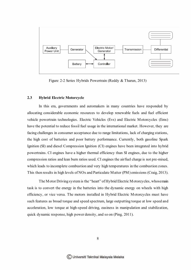
(Reddy & Tharun, 2013). The configuration of the series hybrid electric vehicle is shown in
Figure 2-1 and Figure 2-2. Engine drives the generator to generate power and power is
directly transferred to energy shortage unit or drive motor. Drive motor works in electric
mode to drive the vehicle or in generating model to transfer mechanical energy to electric
energy. The energy of the series hybrid electric vehicle is distributed by the vehicle
controller. Vehicle controller distributes the energy between Auxiliary Power Unit (APU)
and energy shortage unit according to the power demand of driver and parts condition (Wu,
2013).
Figure 2-1 : Parallel Hybrids Powertrain (Reddy & Tharun 2013)
8
Figure 2-2 Series Hybrids Powertrain (Reddy & Tharun, 2013)
2.3 Hybrid Electric Motorcycle
In this era, governments and automakers in many countries have responded by
allocating considerable economic resources to develop renewable fuels and fuel efficient
vehicle powertrain technologies. Electric Vehicles (Evs) and Electric Motorcycles (Ems)
have the potential to reduce fossil fuel usage in the international market. However, they are
facing challenges in consumer acceptance due to range limitations, lack of charging stations,
the high cost of batteries and poor battery performance. Currently, both gasoline Spark
Ignition (SI) and diesel Compression Ignition (CI) engines have been integrated into hybrid
powertrains. CI engines have a higher thermal efficiency than SI engines, due to the higher
compression ratios and lean burn ratios used. CI engines the air/fuel charge is not pre-mixed,
which leads to incomplete combustion and very high temperatures in the combustion zones.
This then results in high levels of NOx and Particulate Matter (PM) emissions (Craig, 2013).
The Motor Driving system is the “heart” of Hybrid Electric Motorcycles, whose main
task is to convert the energy in the batteries into the dynamic energy on wheels with high
efficiency, or vice versa. The motors installed in Hybrid Electric Motorcycles must have
such features as broad torque and speed spectrum, large outputting torque at low speed and
acceleration, low torque at high-speed driving, easiness in manipulation and stabilization,
quick dynamic response, high power density, and so on (Ping, 2011).

9
A schematic diagram for the Hybrid Electric Motorcycle (HEM) is shown in Figure
1. The HCCI engine is used to drive an electrical generator. The electric power from the
generator is used to charge the battery pack utilizing a DC/DC converter, which boosts the
generator output voltage to a level higher than the battery terminal voltage. The wheel motor
is driven by the electric power flow from the battery to propel the vehicle. The engine
combustion and all power flow action are monitored and controlled by an integrated
controller (Craig, 2013).
Figure 2-3: Schematic diagram for the Hybrid Electric Motorcycle (Craig, 2013).
2.4 S imulation and Analysis Phase
In this project, I be assigned to complete the third phase which is simulation and
analysis phase. Simulation and analysis is important phase to complete a project and this can
be shown by previous study. At the same time for complicated geometries, assessment of
this factor and total energy remains elusive, therefore proposed finite element based analysis
of such geometries could directly help determine the maximum achievable energy density.
This approach consists of four steps:
Step 1, a fully parametric model of the flywheel is created to be inputted to ANSYS
(a finite element modelling and analysis software) to form the desired geometry.
Step 2, model obtained in Step 1 is analyzed using ANSYS/LSDYNA, an explicit
code, to obtain the stored kinetic energy and mass of the flywheel.

10
Step 3, the same model is also analyzed using ANSYS, an implicit code, and overall
stress distribution of the flywheel obtained and critical stresses and regions
identified.
Finally, using kinetic energy, mass and maximum stress of the flywheel obtained in
Steps 1–3, an optimization is performed to come up with the maximum obtainable
Specific Energy level, meantime making sure that the maximum equivalent stress is
less than the maximum (Arslan, 2008).
2.4.1 Drive Cycles
In an automotive technology, the research in using flywheel as a secondary power
source begins as in early 70s. Nowadays some automotive manufacturer start to put this
technology inside their cars even some of them uses it in high performance car. However,
the reliability and performance of the flywheel hybrid is uncertain. Therefore, this
technology is still on going further research and refinement. In performance aspect, the major
drawback of flywheel hybrid is in the recharging and storing capability. It only can be charge
using regenerative braking which exist during deceleration phase of driving cycle (Manaf,
2015).
Figure 2-4: Three types of driving drive (Manaf et al. 2015).

11
2.4.2 S tress and Displacement
In this study, energy output that need to be evaluate is the kinetic energy that can be
store by the flywheel. The previous study show that modern technology has enabled a new
application for the age old flywheel in advanced flywheel energy storage systems . These
systems are often called mechanical batteries since electrical energy is input, stored as
rotational mechanical energy, and converted back to electrical energy to provide power on
demand. The Flywheel is designed in 3D modelling CATIA (Reddy, 2015).
2.4.3 Fatigue Life
Fatigue life is a function of the magnitude of the fluctuating stress, geometry of the
specimen and test conditions. An S-N diagram is a plot of the fatigue life at various levels
of fluctuating stress. From previous study stated by Kihyon Kwon and Dan M. Frangopol,
under the repeated or fluctuating application of stresses during voyages, ship fatigue life can
be assessed by using a fatigue reliability method based on the S-N (stress vs. Number of
cycles) approach. Besides, the S-N (stress vs. number of cycles) approach and available sea
loading information are used to evaluate the time-dependent fatigue reliability (Kwon &
Frangopol, 2013).
Figure 2-5: S-N curve
(Source: www.efunda.com/formulae/solid_mechanics/fatigue/images/fatigue_SN_01.gif)

12
CHAPTER 3
METHODOLOGY
3.0 Introduction
The study will be conducted into several phase, where all the details of the simulation
and analysis methods will be show in order to identify the project objectives in more details.
There are several phase of methodology in incorporating flywheel hybrid module in
motorcycle by using simulation and analysis approach.
The phase start with determine the load of the flywheel hybrid module under set up
velocity. The flywheel hybrid module will be run and from intial velocity of 1000 rpm until
maximum velocity of 9000 rpm where these are the standard velocity of motorcycle. For
each set up velocity, the centrifugal force of the FHM will be determined by us ing an
equation of Fc = Iα.
The method are done by continue to the next phase where the next phase is determine
the stress and displacement of the flywheel hybrid module using Finite Element Analysis
(FEA). In this phase, two material are selected for the FHM to be analysed which are carbon
steel and aluminum. The stress and displacement of the FHM for each material will be
determine in order to choose which material can withstand high stress and displacement.
Fatigue prediction of the flywheel hybrid module is the next phase in methodology.
After done the simulation under the set up velocity, the area of the high stress concentration
on the FHM geometry is identify in order to predict the creep. From the creep, the fatigue
area of the FHM where the high stress and displacement can be determine when load is
applied.
Related Documents