processes Article Development and Commissioning of a Small-Scale, Modular and Integrated Plant for the Quasi-Continuous Production of Crystalline Particles Timo Dobler *, Simon Buchheiser, Marco Gleiß and Hermann Nirschl Citation: Dobler, T.; Buchheiser, S.; Gleiß, M.; Nirschl, H. Development and Commissioning of a Small-Scale, Modular and Integrated Plant for the Quasi-Continuous Production of Crystalline Particles. Processes 2021, 9, 663. https://doi.org/10.3390/ pr9040663 Academic Editor: Luis Puigjaner Received: 25 February 2021 Accepted: 7 April 2021 Published: 9 April 2021 Publisher’s Note: MDPI stays neutral with regard to jurisdictional claims in published maps and institutional affil- iations. Copyright: © 2021 by the authors. Licensee MDPI, Basel, Switzerland. This article is an open access article distributed under the terms and conditions of the Creative Commons Attribution (CC BY) license (https:// creativecommons.org/licenses/by/ 4.0/). Karlsruhe Institute of Technology (KIT), Institute of Mechanical Process Engineering and Mechanics, Strasse am Forum 8, 76131 Karlsruhe, Germany; [email protected] (S.B.); [email protected] (M.G.); [email protected] (H.N.) * Correspondence: [email protected]; Tel.: +49-721-608-44136 Abstract: Increasing global competition, volatile markets and the demand for individual products challenge companies in almost all business sectors and require innovative solutions. In the chem- ical and pharmaceutical industries, these include modular design, the integration of several unit operations in one apparatus and the development of small-scale, versatile multipurpose plants. An example for such a modular, integrated and small-scale system is the belt crystallizer. This device combines the process steps cooling crystallization, solid-liquid separation and contact drying in a single plant. The basis of the apparatus is a belt filter in which the vacuum trays below the filter medium are replaced by temperature control and filtration units. Due to identical dimensions, it is possible to arrange the individual functional units in any order, which in turn allows a high degree of flexibility and rapid adaptation to customer requirements. Within the scope of the publication, the commissioning of the belt crystallizer takes place. First of all, the general functionality of the plant concept is demonstrated using sucrose as model system. Further experiments show that the particle size and the distribution width of the manufactured crystals can be specifically influenced by the selected process parameters, e.g., temperature profile during cooling and residence time. Keywords: modularization; plant engineering; crystallization; solid-liquid separation; integrated process design 1. Introduction In almost every industrial sector companies are faced with constantly changing chal- lenges. In the chemical and pharmaceutical industry this includes increasing global com- petition, growing market volatility, short product life cycles and plant lifetimes as well as rising quality demands and the request for individual products in small amounts [1–4]. One approach to meet these challenges successfully and to ensure long-term business success is the establishment of adaptable, small-scale, modular production concepts that combine the flexibility and versatility of a discontinuous multi-product asset with the efficiency and reproducibility of a continuous single-product plant [2,4,5]. The modular design enables a reduction in time-to-market and controlled capacity adjustment along with simple and fast plant maintenance [6,7]. Further positive aspects are the decentralized production close to the customer, short retooling times in case of a product change and lower investment costs due to the recycling of modules [4,8–10]. Despite the advantages, modular production plants are still rarely used in the chemical industry. There are various reasons for this, ranging from the limitations of the technical possibilities due to design guidelines or conflicting goals to the additional construction effort [11]. However, one example that demonstrates the need for and the benefits of modular plants is the container- based production facility EvoTrainer. Evonik already deploys the concept successfully for rapid product development and for the small-scale production of chemicals [11]. Processes 2021, 9, 663. https://doi.org/10.3390/pr9040663 https://www.mdpi.com/journal/processes

Welcome message from author
This document is posted to help you gain knowledge. Please leave a comment to let me know what you think about it! Share it to your friends and learn new things together.
Transcript
processes
Article
Development and Commissioning of a Small-Scale, Modularand Integrated Plant for the Quasi-Continuous Production ofCrystalline Particles
Timo Dobler *, Simon Buchheiser, Marco Gleiß and Hermann Nirschl
�����������������
Citation: Dobler, T.; Buchheiser, S.;
Gleiß, M.; Nirschl, H. Development
and Commissioning of a Small-Scale,
Modular and Integrated Plant for the
Quasi-Continuous Production of
Crystalline Particles. Processes 2021, 9,
663. https://doi.org/10.3390/
pr9040663
Academic Editor: Luis Puigjaner
Received: 25 February 2021
Accepted: 7 April 2021
Published: 9 April 2021
Publisher’s Note: MDPI stays neutral
with regard to jurisdictional claims in
published maps and institutional affil-
iations.
Copyright: © 2021 by the authors.
Licensee MDPI, Basel, Switzerland.
This article is an open access article
distributed under the terms and
conditions of the Creative Commons
Attribution (CC BY) license (https://
creativecommons.org/licenses/by/
4.0/).
Karlsruhe Institute of Technology (KIT), Institute of Mechanical Process Engineering and Mechanics,Strasse am Forum 8, 76131 Karlsruhe, Germany; [email protected] (S.B.); [email protected] (M.G.);[email protected] (H.N.)* Correspondence: [email protected]; Tel.: +49-721-608-44136
Abstract: Increasing global competition, volatile markets and the demand for individual productschallenge companies in almost all business sectors and require innovative solutions. In the chem-ical and pharmaceutical industries, these include modular design, the integration of several unitoperations in one apparatus and the development of small-scale, versatile multipurpose plants. Anexample for such a modular, integrated and small-scale system is the belt crystallizer. This devicecombines the process steps cooling crystallization, solid-liquid separation and contact drying in asingle plant. The basis of the apparatus is a belt filter in which the vacuum trays below the filtermedium are replaced by temperature control and filtration units. Due to identical dimensions, it ispossible to arrange the individual functional units in any order, which in turn allows a high degreeof flexibility and rapid adaptation to customer requirements. Within the scope of the publication, thecommissioning of the belt crystallizer takes place. First of all, the general functionality of the plantconcept is demonstrated using sucrose as model system. Further experiments show that the particlesize and the distribution width of the manufactured crystals can be specifically influenced by theselected process parameters, e.g., temperature profile during cooling and residence time.
Keywords: modularization; plant engineering; crystallization; solid-liquid separation; integratedprocess design
1. Introduction
In almost every industrial sector companies are faced with constantly changing chal-lenges. In the chemical and pharmaceutical industry this includes increasing global com-petition, growing market volatility, short product life cycles and plant lifetimes as well asrising quality demands and the request for individual products in small amounts [1–4].One approach to meet these challenges successfully and to ensure long-term businesssuccess is the establishment of adaptable, small-scale, modular production concepts thatcombine the flexibility and versatility of a discontinuous multi-product asset with theefficiency and reproducibility of a continuous single-product plant [2,4,5]. The modulardesign enables a reduction in time-to-market and controlled capacity adjustment alongwith simple and fast plant maintenance [6,7]. Further positive aspects are the decentralizedproduction close to the customer, short retooling times in case of a product change andlower investment costs due to the recycling of modules [4,8–10]. Despite the advantages,modular production plants are still rarely used in the chemical industry. There are variousreasons for this, ranging from the limitations of the technical possibilities due to designguidelines or conflicting goals to the additional construction effort [11]. However, oneexample that demonstrates the need for and the benefits of modular plants is the container-based production facility EvoTrainer. Evonik already deploys the concept successfully forrapid product development and for the small-scale production of chemicals [11].
Processes 2021, 9, 663. https://doi.org/10.3390/pr9040663 https://www.mdpi.com/journal/processes
Processes 2021, 9, 663 2 of 11
In addition to modularization, the integration of different unit operations in oneplant becomes more and more important. The main advantages are the reduction intransport facilities such as pumps, minimization of the risk of contamination, smaller spacerequirements and simplified implementation of safety standards, e.g., when using solvents.In contrast, optimizing the individual process steps is a challenge. Since these are usuallylinked to each other via predefined machine parameters, an intelligent system control anda high degree of automation are required to improve the overall process [12]. Despitethis limitation, there are some integrated plants in the field of process engineering [13–16].Among these are the Titus-Nutschen-Dryer [15] and the Konfiltro, which combines filtrationand drying on a belt filter and serves as a basis for the apparatus concept presentedin this publication [13,14]. Compared to the classic design of the Konfiltro, the newlydeveloped plant consists of modular equipment and includes a cooling crystallization stepin addition to filtration and drying. Thus, the apparatus combines the advantages of bothmodularization and integration and extends the application area, which reaches from theproduction to the separation of crystalline particles. To demonstrate the basic functionalityof the plant, the initial commissioning is followed by tests with the system sucrose/water.
2. Materials and Methods2.1. Belt Crystallizer2.1.1. Apparatus Concept and Process Procedure
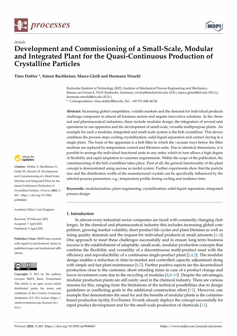
The belt crystallizer is a quasi-continuous apparatus, which includes the process stepscooling crystallization, solid-liquid separation and contact drying. The general workingprinciple has already been described by Löbnitz [12]. The basis of the plant is a belt filter. Incontrast to the conventional design, flexible and exchangeable functional units replace thevacuum trays below the filter medium. While there are temperature control segments inthe crystallization zone, filtration modules are installed in the solid-liquid separation area.For drying the crystals, temperature control units are used again. The process chamberin which particle production takes place is located above the filter medium and passesthrough the process chain from left to right. Figure 1 shows the described apparatusconcept schematically.
Figure 1. Apparatus concept and process procedure. At time t = t0 there is an inoculated and saturated solution. Byreducing the temperature T suspension has formed at t = t1. The suspension is subsequently separated by an appliedpressure difference ∆p and leaves the solid-liquid separation zone at t = t2. Due to the input of thermal energy E, only thedried product is left at t = t3.
Referring to the same figure, the process procedure is explained. In a first step,an inoculated, saturated solution is added to the process chamber at time t = t0 andsubsequently cooled in the crystallization zone. This causes supersaturation in the system,which is reduced by the formation of crystalline particles (t = t1). In the next stage, thesolid and liquid components are separated by applying a vacuum and the resulting filtercake is mechanically demoistened (t = t2). Optionally, an additional displacement washing
Processes 2021, 9, 663 3 of 11
occurs within the same zone. The filter cake is then dried by the input of thermal energyand removed from the filter at time t = t3.
2.1.2. Apparatus Implementation
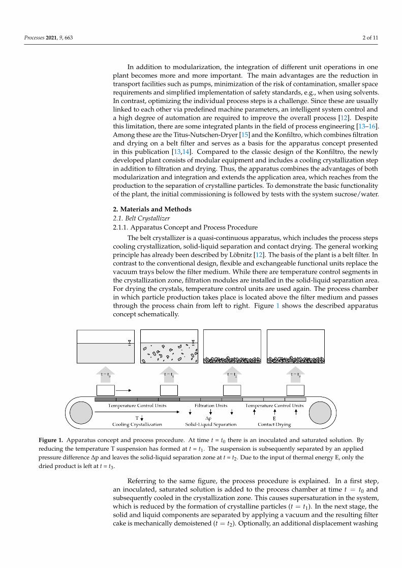
The laboratory apparatus was a prototype and measured 1340 mm in length, 350 mmin width and 510 mm in height. It was controlled by a superordinate process control system.An image of the entire plant can be seen in Figure 2.
Figure 2. Laboratory apparatus. The plant consisted of flexible functional units (1), filter medium (2), process chamber (3),cake washing device (4), scraper (5) and washing tub (6).
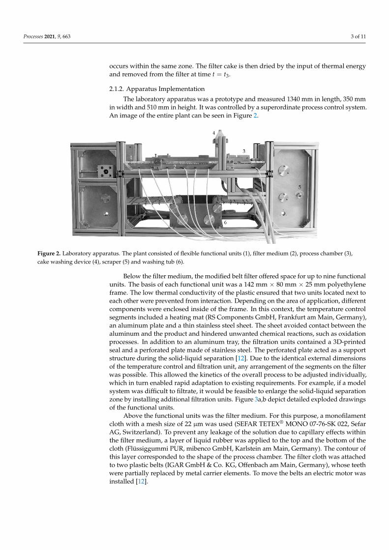
Below the filter medium, the modified belt filter offered space for up to nine functionalunits. The basis of each functional unit was a 142 mm × 80 mm × 25 mm polyethyleneframe. The low thermal conductivity of the plastic ensured that two units located next toeach other were prevented from interaction. Depending on the area of application, differentcomponents were enclosed inside of the frame. In this context, the temperature controlsegments included a heating mat (RS Components GmbH, Frankfurt am Main, Germany),an aluminum plate and a thin stainless steel sheet. The sheet avoided contact between thealuminum and the product and hindered unwanted chemical reactions, such as oxidationprocesses. In addition to an aluminum tray, the filtration units contained a 3D-printedseal and a perforated plate made of stainless steel. The perforated plate acted as a supportstructure during the solid-liquid separation [12]. Due to the identical external dimensionsof the temperature control and filtration unit, any arrangement of the segments on the filterwas possible. This allowed the kinetics of the overall process to be adjusted individually,which in turn enabled rapid adaptation to existing requirements. For example, if a modelsystem was difficult to filtrate, it would be feasible to enlarge the solid-liquid separationzone by installing additional filtration units. Figure 3a,b depict detailed exploded drawingsof the functional units.
Above the functional units was the filter medium. For this purpose, a monofilamentcloth with a mesh size of 22 µm was used (SEFAR TETEX® MONO 07-76-SK 022, SefarAG, Switzerland). To prevent any leakage of the solution due to capillary effects withinthe filter medium, a layer of liquid rubber was applied to the top and the bottom of thecloth (Flüssiggummi PUR, mibenco GmbH, Karlstein am Main, Germany). The contour ofthis layer corresponded to the shape of the process chamber. The filter cloth was attachedto two plastic belts (IGAR GmbH & Co. KG, Offenbach am Main, Germany), whose teethwere partially replaced by metal carrier elements. To move the belts an electric motor wasinstalled [12].
Processes 2021, 9, 663 4 of 11
Figure 3. Exploded drawings. (a) Temperature control unit, (b) filtration unit, (c) cake washing device, (d) process chamberand (e) cake removal device.
The rectangular process chamber was on top of the filter medium. The underside ofthe component contained a seal. The two front sides were equipped with metal angles. Forthe exact positioning and transport of the process chamber, the angles were provided withholes matching the metal carrier elements of the toothed belts [12]. Figure 3d shows thegeneral design of the process chamber.
In order to remove impurities from the filter cake, a device for cake washing wasinstalled in the solid-liquid separation zone. The unit was made of a universally applicableupper part, a seal and a sub part that was individually adapted to the process parametersand the model system. To achieve a homogeneous distribution of the washing liquidover the entire outlet area, there was a flow divider inside the upper part. In addition,the bottom part had outlet cones that prevented the uncontrolled pooling of the escapingwashing liquid. Figure 3c illustrates the entire element.
At the end of the belt section, the cake was removed from the filter. For this purpose,a scraper was integrated into the process. The device consisted of an aluminum shaft, aholder and a 3D-printed lip and can be taken from Figure 3e. The modular design of thescraper allowed variation of the removal angle as well as the changing of the material andgeometry of the removal lip. Along with the easy replacement of damaged components,the tool offers a high degree of individuality and flexibility.
For cleaning the used filter medium, an aluminum wash tub was implemented. Thetub was equipped with a separate inlet and outlet for the washing liquid and served to freethe returning filter cloth from existing residues and deposits.
2.2. Particle System
The particulate system selected for the experimental studies was sucrose (Fein Zucker,Südzucker AG, Mannheim, Germany). The chemical connection was hydrolyzable by theabsorption of water, which in turn ensured a high solubility. In order to determine thesolubility of sucrose in water a correlation according to Vavrinecz described in Mathlouthiand Reiser [17] is used in Equation (1). Herein, φ represents the solid mass fraction asfunction of the temperature T.
φ = 64.47 + 8.222 10−2 T + 1.6169 10−3 T2 − 1.558 10−6 T3 − 4.63 10−8 T4 (1)
Another important physicochemical property is the dynamic viscosity η. The parame-ter is calculated to
η = 10 A + BT + 273.15 + C
T − 43.15 (2)
The coefficients, A, B and C and depend on the molar ratio of sucrose to water y andresult in [18]
A = − 2.038 − 13.627 y − 17.912 y2 + 56.426 y3, (3)
Processes 2021, 9, 663 5 of 11
B = 513.367 + 10, 740.329 y − 16, 781.321 y2 + 14, 142.897 y3, (4)
C = 16.993 + 34.442 y + 3915.947 y2 − 6839.469 y3 (5)
The basis for all crystallization experiments (Sections 3.2–3.5) was 64.57 g of a sucrosesolution saturated at 60 ◦C. For this purpose, 16.61 g ultrapure water and 47.96 g solidwere mixed with a magnetic stirrer (RCT basic, IKA-Werke GmbH & Co. KG, Staufen,Germany) at a speed of 600 rpm for a time period of four hours. During the mixing process,the temperature was held at 65 ◦C to guarantee the complete dissolution of all particles.Immediately before the start of the experiment, the undersaturated solution was cooled to60 ◦C and 0.13 g of seed crystals (Puderzucker fein, Südzucker AG, Mannheim, Germany)were added. The components were mixed for 60 s and fed into the process chamber locatedon the belt crystallizer.
2.3. Centrifugation Experiments
To characterize the crystals formed in the process, an optical centrifuge (LUMiSizer®,LUM GmbH, Berlin, Germany) was used. The device measured the light transmission val-ues at a wavelength of 865 nm and converted them into extinction profiles. The extinctionvalues served as a foundation for the calculation of settling velocity and size distribution.Detloff et al. [19] gave a detailed explanation of the apparatus and the measuring principle.
The experiments performed in this study were all conducted at a speed of 1000 rpm, atemperature of 20 ◦C and a solids volume fraction of 0.008. To adjust this volume fraction,the sample taken from the process was diluted with a sucrose solution saturated at 20 ◦C. Inorder to calculate the amount of solution required for the dilution, it was assumed that thesupersaturation within the sample had completely dissipated during the cooling process.The evaluation of the measurement data considered spherical particles with an equivalentdiameter xeq, which settled according to Stokes [20].
2.4. Filtration Experiments
A characteristic parameter in the field of filtration is the filtration resistance, whichcomprises the filter cake resistance rc and the filter medium resistance RM. To determinethe resistance values, tests using a pressure nutsche were made. Thereby, a mixture ofsucrose and ultrapure water with a solid mass fraction of 0.74 served as suspension. Withinthe scope of this work, both unused and used filter media were investigated. The usedones were contaminated close to the process by a crystallization experiment performed inadvance on the surface of the filter cloth. VDI 2762 explained the principle test setup aswell as the procedure and the analysis of the experiments [21].
For describing the filtration process, the equation of cake-forming filtration (Equa-tion (6)) was used. The expression originates in Darcy′s law and links the filtrate volumeV with the concentration constant κ, dynamic viscosity η, filter area A, applied pressuredifference ∆p and the filtration resistances rc and RM [20].
tV
=κ η rc
2 A2 ∆pV +
η RMA ∆p
(6)
The graphical application of Equation (6) results in a linear graph, where the ordinateintercept a allows the calculation of the filter medium resistance RM following
RM = aA ∆p
η(7)
In addition, the height-specific filter cake resistance rc can be determined dependingon the slope b by the formula
rc = b2 A2 ∆p
κ η(8)
Processes 2021, 9, 663 6 of 11
Besides the tests with the pressure nutsche, filtration and demoisturization experi-ments were performed on the belt crystallizer. To evaluate these studies, the solvent contentsc into the filter cake was calculated according to
sc =mc,w − mc,d
mc,w(9)
The mass of the wet cake mc,w was measured immediately after the filtration processwith a laboratory balance. To determine the dry mass mc,d the cake was then completelydehumidified in a drying oven at 60 ◦C and weighed again.
3. Results and Discussion3.1. Commissioning of the Temperature Control Units in the Crystallization Zone
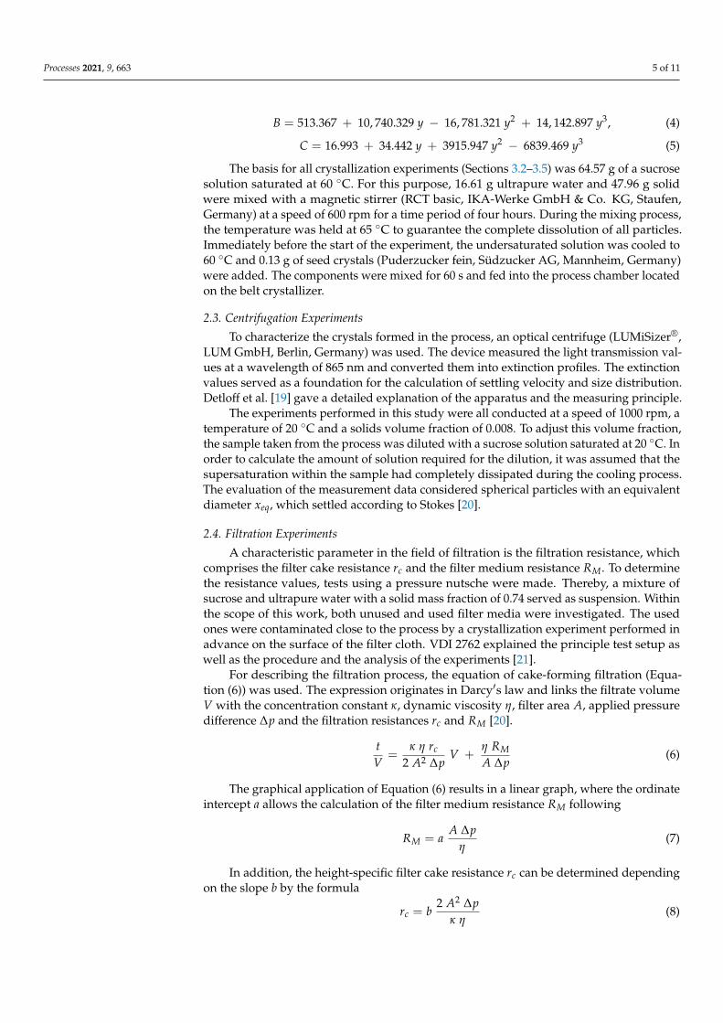
Initially, the focus was on the commissioning of the temperature control units in thecrystallization zone. Considering that the temperature profile influences the supersatura-tion of the solution and thus also the properties of the resulting crystals, it is essential to beable to control the cooling curve during the particle formation process. Therefore, the aimof a first study is the realization of different temperature profiles [22]. For this purpose, thetemperature of the solution was reduced from 60 to 20 ◦C within 1800 s in each case. Tocool the solution, there were six temperature control units connected in series. The desiredcurves and the prevailing segment temperatures in the individual stages are given on theleft hand side of Figure 4.
Figure 4. (a) Desired temperature curves of the solution (solid line) and temperature of the functionalunits (dot-dash) during progressive, linear and degressive cooling. The residence time per segment is300 s. (b) Temperature of the solution at different cooling curves. While there is no deviation betweenthe set and actual values at low to medium cooling rates, the high viscosity of the sucrose solutioncauses differences at high cooling rates.
The basis for the experimental tests was a sucrose solution with a solid mass fractionof 0.67. In order to determine the temperature, an infrared thermometer (5020-0385 ScanTemp 385, Dostmann electronic GmbH, Wertheim-Reicholzheim, Germany) allowed themeasurement of the surface temperature of the solution at intervals of 60 s. The right sideof Figure 4 shows the data obtained.
It is obvious that the cooling curve can be influenced and adjusted by the segmenttemperature. A good agreement between target and actual values is apparent at small tomedium cooling rates below 8 ◦C per residence level. For temperature differences of morethan 20 ◦C between two adjacent functional units, deviations from the target curve occurmore frequently. This behavior appears, for example, at an early stage of the degressivecurve and at an advanced stage of the progressive one. The existing differences result fromthe high viscosity of the solution and the inhibited heat conduction.
Processes 2021, 9, 663 7 of 11
3.2. Influence of the Temperature Profile on the Crystal Properties
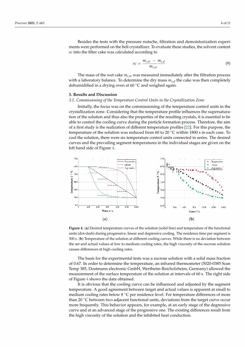
In the following, the influence of the temperature profile on the crystal properties isinvestigated in detail. The right side of Figure 4 indicates the temperature curves selectedfor the experiments. Directly after the cooling procedure, a representative sample of 500 µLwas taken by means of a laboratory pipette (Research® plus, Eppendorf AG, Hamburg,Germany). Assuming the complete decomposition of the supersaturation, the suspensionwas diluted to a solid volume fraction of 0.008 and measured in the centrifugal field.
Figure 5 shows the determined cumulative particle size distributions. It is notice-able that the temperature curve influences the properties of the crystals. While degres-sive cooling produces rather small particles with the volume-based median diameterx50,3 = 26.2 ± 1.0 µm, progressive temperature reduction forms particles with a diameterof 35.7 ± 3.0 µm. In the case of a linear temperature profile, the plant generates crystalswith a size of 31.0 ± 1.3 µm. The differences result from the prevailing supersaturation inthe system. In the progressive cooling process, the system is only slightly supersaturatedat the beginning. This is why primarily crystal growth takes place. The growing rate iscomparatively high due to the temperature, thus the particles enlarge rapidly. In contrast,the system is initially highly supersaturated in the case of a degressive progression. Thisin turn leads to an intensified nucleation instead of the growth of existing crystals. As aresult, the median particle diameter is quite small.
Figure 5. Particle size distribution of the crystals formed at different cooling curves, whereby the totalprocess time is 1800 s in each case. The figure shows that the temperature profile clearly influencesthe crystal properties.
Apart from the particle size, the cooling curve also influences the distribution width. Acharacteristic parameter is the span, which links the particle sizes x10,3, x50,3 and x90,3 and isgiven in Table 1. In the executed tests, the widest distribution (span = 1.1 ± 0.1) is obtainedby a progressive cooling, whereas a degressive temperature profile results in a narrowdistribution with a span of 0.6± 0.2. Analogous to the median particle size, the distributionwidth for a linear ramp is between the progressive and the degressive cooling curves. Onceagain, the process conditions are responsible for the differences. The increasingly smallertemperature gradients during degressive cooling allow the uniform growth of the nucleiand the seed crystals. In contrast, in progressive cooling, the supersaturation ratio risesabruptly from a process time of approximately 1200 s onward. Hence, nucleation occurs,whereby small particles are formed and broaden the distribution.
Processes 2021, 9, 663 8 of 11
Table 1. Median particle size and span at different cooling curves.
Cooling Curve Median Particle Sizex50,3 in µm
Span(x90,3−x10,3)/x50,3
Progressive 35.7 ± 3.0 1.1 ± 0.1Linear 31.0 ± 1.3 0.9 ± 0.1
Degressive 26.2 ± 1.0 0.6 ± 0.2
3.3. Influence of Residence Time on the Crystal Properties
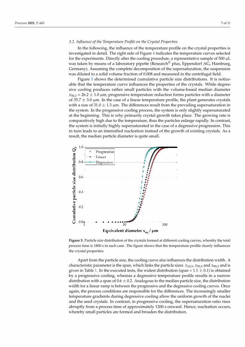
The properties of the particles are not only influenced by the temperature profile, butalso by the residence time in the crystallization area. Consequently, further experimentsfocused on the investigation of this process parameter. Regardless of the selected residencetime, a six-stage linear cooling took place in all cases. The temperatures prevailing inthe individual stages were 60, 52, 44, 36, 28 and 20 ◦C. The residence time per segmentvaried from 300 to 900 s, resulting in overall times of 1800 to 5400 s. In order to analyze themanufactured crystals, measurements in the centrifugal field were carried out identicallyto Section 3.2.
Figure 6 shows the obtained particle size distributions. In principle, it can be seen thatthe particles become larger with increasing residence time. The median size is 31.0 ± 1.3 µmat an interval of 300 s and increases to 43.8 ± 4.5 µm when resting for 600 s. The largestparticle diameter is reached at a duration of 900 s per functional unit. Here, the averageparticle size is 54.5 ± 5.6 µm.
Figure 6. Particle size distribution during linear cooling as a function of the residence time. Inprinciple, it can be seen that the formed particles become larger as the process time increases. Thedistribution width, however, remains almost constant.
Moreover, the experiments demonstrate that the residence time has only a marginalinfluence on the distribution width. The span assumes values between 0.9 and 1.0 andis within the range of the statistical deviation. The shift towards larger crystals withincreasing crystallization time is due to longer growth and aging times, while the almostconstant distribution width is a result of the similar cooling profiles.
3.4. Influence of the Crystallization Process on the Filter Medium
The three previous sections show that the laboratory plant is basically suitable forthe production of particles by a cooling crystallization. To ensure that the crystallizationprocess does not block the pores of the filter medium and thus greatly slow down or
Processes 2021, 9, 663 9 of 11
completely prevent the subsequent solid-liquid separation, filtration tests were carried outon a pressure nutsche. In this context, the cloth was soiled close to the process and the filtermedium resistance as well as the total resistance were determined. The total resistanceis the sum of filter medium resistance and filter cake resistance, while the cake resistanceis the product of the height specific cake resistance rc and cake height hc. Experiments inwhich an unused filter cloth was examined serve as reference. The calculated parametersand the relation of the averaged filter medium resistance to the mean total resistance canbe found in Table 2.
Table 2. Calculated filtration resistances and ratio of the filter medium to total resistance.
Condition Medium ResistanceRM in 109 m−1
Total ResistanceR in 109 m−1
Ratio¯RM/
¯R
Unused 1.04 ± 0.36 10.05 ± 4.67 0.10Used 1.97 ± 0.76 16.45 ± 5.00 0.12
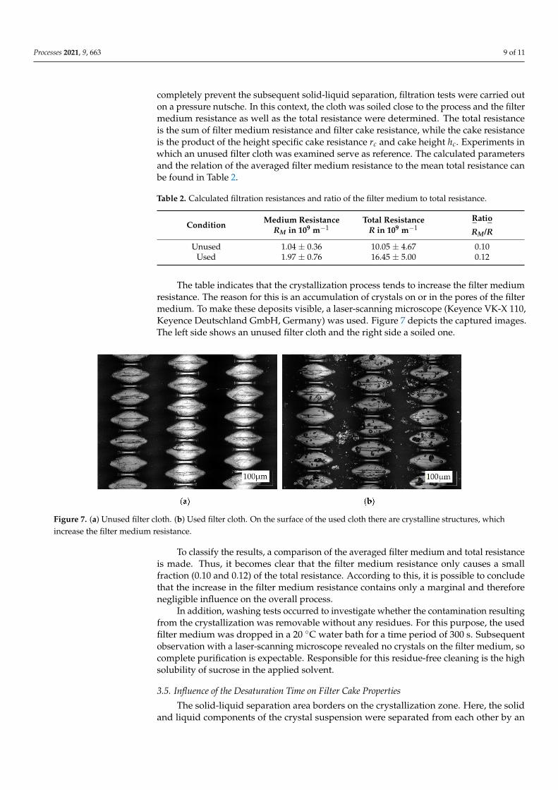
The table indicates that the crystallization process tends to increase the filter mediumresistance. The reason for this is an accumulation of crystals on or in the pores of the filtermedium. To make these deposits visible, a laser-scanning microscope (Keyence VK-X 110,Keyence Deutschland GmbH, Germany) was used. Figure 7 depicts the captured images.The left side shows an unused filter cloth and the right side a soiled one.
Figure 7. (a) Unused filter cloth. (b) Used filter cloth. On the surface of the used cloth there are crystalline structures, whichincrease the filter medium resistance.
To classify the results, a comparison of the averaged filter medium and total resistanceis made. Thus, it becomes clear that the filter medium resistance only causes a smallfraction (0.10 and 0.12) of the total resistance. According to this, it is possible to concludethat the increase in the filter medium resistance contains only a marginal and thereforenegligible influence on the overall process.
In addition, washing tests occurred to investigate whether the contamination resultingfrom the crystallization was removable without any residues. For this purpose, the usedfilter medium was dropped in a 20 ◦C water bath for a time period of 300 s. Subsequentobservation with a laser-scanning microscope revealed no crystals on the filter medium, socomplete purification is expectable. Responsible for this residue-free cleaning is the highsolubility of sucrose in the applied solvent.
3.5. Influence of the Desaturation Time on Filter Cake Properties
The solid-liquid separation area borders on the crystallization zone. Here, the solidand liquid components of the crystal suspension were separated from each other by an
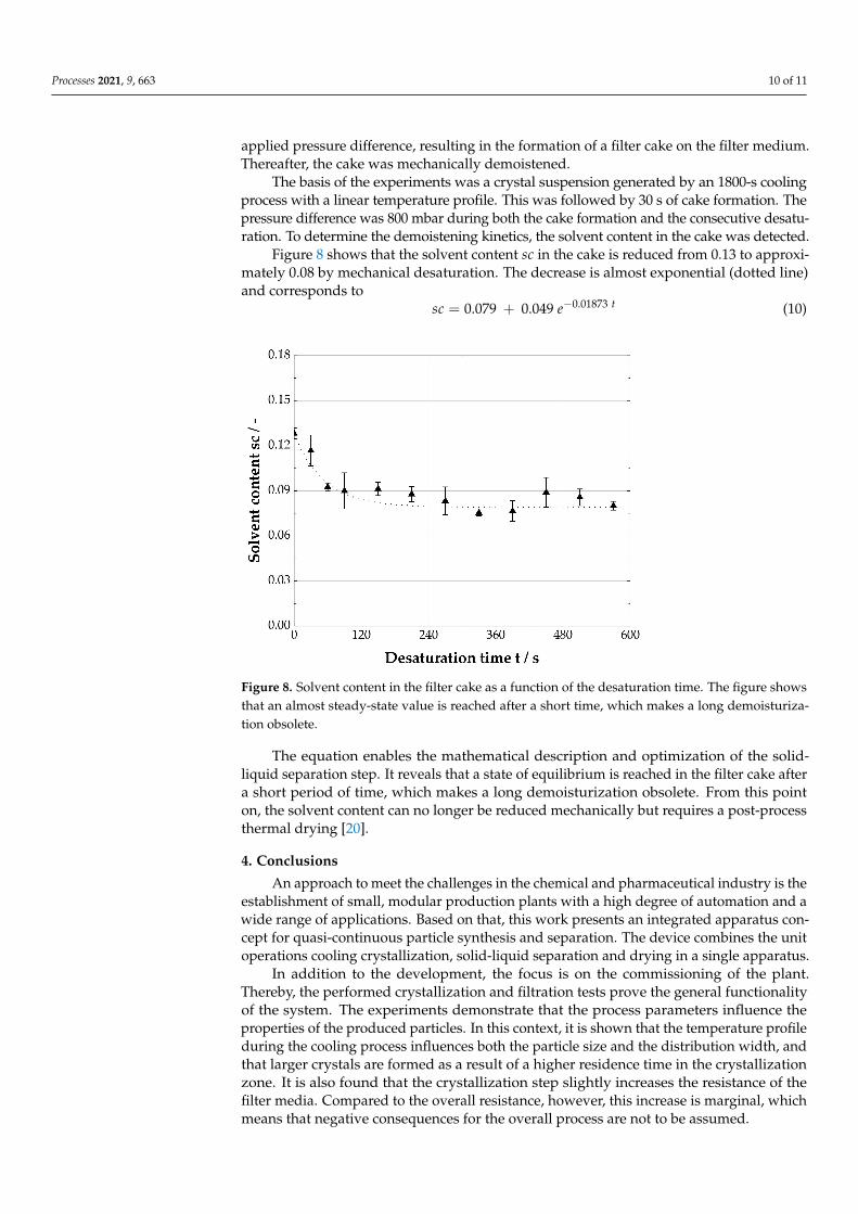
Processes 2021, 9, 663 10 of 11
applied pressure difference, resulting in the formation of a filter cake on the filter medium.Thereafter, the cake was mechanically demoistened.
The basis of the experiments was a crystal suspension generated by an 1800-s coolingprocess with a linear temperature profile. This was followed by 30 s of cake formation. Thepressure difference was 800 mbar during both the cake formation and the consecutive desatu-ration. To determine the demoistening kinetics, the solvent content in the cake was detected.
Figure 8 shows that the solvent content sc in the cake is reduced from 0.13 to approxi-mately 0.08 by mechanical desaturation. The decrease is almost exponential (dotted line)and corresponds to
sc = 0.079 + 0.049 e−0.01873 t (10)
Figure 8. Solvent content in the filter cake as a function of the desaturation time. The figure showsthat an almost steady-state value is reached after a short time, which makes a long demoisturiza-tion obsolete.
The equation enables the mathematical description and optimization of the solid-liquid separation step. It reveals that a state of equilibrium is reached in the filter cake aftera short period of time, which makes a long demoisturization obsolete. From this pointon, the solvent content can no longer be reduced mechanically but requires a post-processthermal drying [20].
4. Conclusions
An approach to meet the challenges in the chemical and pharmaceutical industry is theestablishment of small, modular production plants with a high degree of automation and awide range of applications. Based on that, this work presents an integrated apparatus con-cept for quasi-continuous particle synthesis and separation. The device combines the unitoperations cooling crystallization, solid-liquid separation and drying in a single apparatus.
In addition to the development, the focus is on the commissioning of the plant.Thereby, the performed crystallization and filtration tests prove the general functionalityof the system. The experiments demonstrate that the process parameters influence theproperties of the produced particles. In this context, it is shown that the temperature profileduring the cooling process influences both the particle size and the distribution width, andthat larger crystals are formed as a result of a higher residence time in the crystallizationzone. It is also found that the crystallization step slightly increases the resistance of thefilter media. Compared to the overall resistance, however, this increase is marginal, whichmeans that negative consequences for the overall process are not to be assumed.
Processes 2021, 9, 663 11 of 11
Author Contributions: Conceptualization, T.D.; Data curation, T.D.; Formal analysis, T.D.; Fundingacquisition, H.N.; Investigation, S.B.; Methodology, T.D.; Project administration, H.N.; Supervision,H.N.; Validation, T.D. and S.B.; Visualization, T.D.; Writing—original draft, T.D.; Writing—reviewand editing, T.D., M.G. and H.N. All authors have read and agreed to the published version ofthe manuscript.
Funding: The authors thank the German Federal Ministry for Economic Affairs and Energy for thefinancial support of this work. This research was made within the scope of the ENPRO initiative(support code: 03ET1652E). Furthermore, we acknowledge support by the KIT-Publication Fund ofthe Karlsruhe Institute of Technology.
Data Availability Statement: Not applicable.
Conflicts of Interest: The authors have declared no conflict of interest.
References1. Lier, S.; Wörsdörfer, D.; Grünewald, M. Wandlungsfähige Produktionskonzepte: Flexibel, Mobil, Dezentral, Modular, Beschleu-
nigt. Chem. Ing. Tech. 2015, 87, 1147–1158. [CrossRef]2. Bieringer, T.; Buchholz, S.; Kockmann, N. Future Production Concepts in the Chemical Industry: Modular—Small-Scale—
Continuous. Chem. Eng. Technol. 2013, 36, 900–910. [CrossRef]3. Lang, J.; Stenger, F.; Schütte, R. Chemieanlagen der Zukunft—Unikate und/oder Module. Chem. Ing. Tech. 2012, 883–884. [CrossRef]4. Lier, S.; Paul, S.; Ferdinand, D.; Grünewald, M. Modulare Verfahrenstechnik: Apparateentwicklung für wandlungsfähige
Produktionssysteme. Chem. Ing. Tech. 2016, 88, 1444–1454. [CrossRef]5. Seifert, T.; Sievers, S.; Bramsiepe, C.; Schembecker, G. Small scale, modular and continuous: A new approach in plant design.
Chem. Eng. Process. Process. Intensif. 2012, 52, 140–150. [CrossRef]6. Fleischer, C.; Wittmann, J.; Kockmann, N.; Bieringer, T.; Bramsiepe, C. Sicherheitstechnische Aspekte bei Planung und Bau
modularer Produktionsanlagen. Chem. Ing. Tech. 2015, 87, 1258–1269. [CrossRef]7. Reitze, A.; Jürgensmeyer, N.; Lier, S.; Kohnke, M.; Riese, J.; Grünewald, M. Auf dem Weg zur Smart Factory: Modulare, intelligente
Konzepte für die Produktion von Spezialchemikalien der Zukunft. Angew. Chem. 2018, 130, 4318–4324. [CrossRef]8. VDI-Gesellschaft Verfahrenstechnik und Chemieingenieurwesen. Process Engineering Plants—Modular Plants—Fundamentals and
Planning Modular Plants; Beuth Verlag GmbH: Berlin, Germany, 2020.9. Hohmann, L.; Kössl, K.; Kockmann, N.; Schembecker, G.; Bramsiepe, C. Modules in process industry—A life cycle definition.
Chem. Eng. Process. Process. Intensif. 2017, 111, 115–126. [CrossRef]10. Baldea, M.; Edgar, T.F.; Stanley, B.L.; Kiss, A.A. Modular manufacturing processes: Status, challenges, and opportunities. AIChE J.
2017, 63, 4262–4272. [CrossRef]11. Bieringer, T.; Bramsiepe, C.; Brand, S.; Brodhagen, A.; Dreiser, C.; Fleischer-Trebes, C.; Kockmann, N.; Lier, S.; Schmalz, D.;
Schwede, C.; et al. Modulare Anlagen: Flexible Chemische Produktion durch Modularisierung und Standardisierung—Status quo undzukünftige Trends; DECHEMA e.V.: Frankfurt, Germany, 2017.
12. Löbnitz, L. Auslegung des Separationsprozesses und Entwicklung Neuer Verfahrenskonzepte zur Integrierten Produktion und SeparationKristalliner Aminosäuren; Karlsruher Institut für Technologie: Karlsruhe, Germany, 2020.
13. Gehrmann, D.; Schweigler, N. Device for Continuous Filtration and Drying of a Solid Suspension. U.S. Patent No. 5,527,458, 18June 1996.
14. Schweigler, N.; Gehrmann, D.; Bamberger, T.; Tichy, J. Kontinuierliche Filtration und Trocknung auf einem neuartigen Filtertrock-ner (Konfiltro). Chem. Ing. Tech. 1995, 67, 1186–1187. [CrossRef]
15. Thurner, F. Der Titus-Nutsch-Trockner—Neue Wege der Produktisolierung. Chem. Ing. Tech. 1990, 62, 753–755. [CrossRef]16. Capellades, G.; Neurohr, C.; Azad, M.; Brancazio, D.; Rapp, K.; Hammersmith, G.; Myerson, A.S. A Compact Device for the
Integrated Filtration, Drying, and Mechanical Processing of Active Pharmaceutical Ingredients. J. Pharm. Sci. 2020, 109, 1365–1372.[CrossRef] [PubMed]
17. Mathlouthi, M.; Reiser, P. Sucrose: Properties and Applications; Springer US: Boston, MA, USA, 1995.18. Pot, A. Industrial Sucrose Crystallisation: A Study on the Development of Crystal Size Distributions in Continuous and Batch Sucrose
Suspension Crystallisers; Technische Universität Delft: Delft, The Netherlands, 1983.19. Detloff, T.; Sobisch, T.; Lerche, D. Particle Size Distribution by Space or Time Dependent Extinction Profiles obtained by Analytical
Centrifugation. Part. Part. Syst. Charact. 2006, 23, 184–187. [CrossRef]20. Anlauf, H. Wet Cake Filtration: Fundamentals, Equipment, Strategies; WILEY VCH: Weinheim, Germany, 2020.21. VDI-Gesellschaft Verfahrenstechnik und Chemieingenieurwesen. Mechanical Solid-Liquid Separation by Cake Filtration—
Determination of Filter Cake Resistance; Beuth Verlag GmbH: Berlin, Germany, 2010.22. Elahi, M. Untersuchungen zur Optimierung der Kühlrate der Kühlungskristallisation von Nachprodukt-Kristallsuspensionen bei der
Saccharosegewinnung; Technische Universität Berlin: Berlin, Germany, 2004.
Related Documents