DEVELOPMENT AND APPLICATION OF NEW CUTTING TOOL MATERIALS R Wertheim 1 , A Layyous 2 , J Harpaz 3 1 Iscar Ltd., Israel, Vice President CIRP 2 R&D Materials, Iscar Ltd., Israel 3 CEO IMC - Iscar Ltd., Israel Abstract The development of new cutting tool materials during the last few years is based mainly on submicron hardmetal substrates as well as on new PVD and CVD coatings. The development of submicron and nano- powders with higher strength and higher fracture toughness solves problems in machining high-temp alloys, hard materials, and in dry cutting. Based on physical models used to calculate stress in the substrate and in various coating layers, it is possible to recommend PVD and CVD coatings for interrupted cutting operations such as milling, parting, and drilling or in some cases also for continuous operations like turning and threading. Compression stresses in PVD coating have the advantage in interrupted and impact type of operations, while CVD coating with larger thickness and tensile stress in the coating performs better in continuous operations and higher speeds. The use of TiAlN coating has the advantage in dry and high-speed machining compared to the TiN and TiCN coatings. The use of new coating processes in lower temperatures (MT) improves toughness and tool life in turning. A wide range of ceramic-based tools are developed and used successfully to cover the high-speed machining of materials. Various examples are shown to demonstrate the application range of the various new tool materials. The development of new materials is influenced more and more by the demand for high-speed machining (HSM), dry cutting (DC), and hard cutting (HC). Keywords: Cutting Tool Material, Coating, Machining 1 INTRODUCTION The demand for cost efficiency in production and the development of new products ranging widely in complexity, material composition, size, and surface finish have required industry to develop new cutting materials and to adopt new machining strategies for optimization of the machining process.[1] New materials have also been developed and adopted for cost and performance optimization in high-speed machining conditions (HSM), especially high cutting speed and higher feeds. Furthermore, new materials are used also in dry cutting which is becoming more and more popular. It is well known that the machining process is influenced not only by machining conditions but the coolant system used as well. If machining can be done dry (DC) without coolant, a significant cost saving is achieved. The question that arises is this: by using new cutting tool materials or coatings, can the coolant be completely eliminated, or can we minimize coolant consumption in metal cutting without loss in productivity.[2] In addition, and mainly due to the near-net technology, products are machined directly to final shape and size after heat treatment. This requires hard cutting (HC) of the workpiece and depends especially on the features of the cutting tool materials and cutting conditions.

Welcome message from author
This document is posted to help you gain knowledge. Please leave a comment to let me know what you think about it! Share it to your friends and learn new things together.
Transcript

DEVELOPMENT AND APPLICATION OF NEW CUTTING TOOL MATERIALS
R Wertheim1, A Layyous2, J Harpaz3
1Iscar Ltd., Israel, Vice President CIRP2R&D Materials, Iscar Ltd., Israel
3CEO IMC - Iscar Ltd., Israel
AbstractThe development of new cutting tool materials during the last few years is based mainly on submicronhardmetal substrates as well as on new PVD and CVD coatings. The development of submicron and nano-powders with higher strength and higher fracture toughness solves problems in machining high-temp alloys,hard materials, and in dry cutting. Based on physical models used to calculate stress in the substrate and invarious coating layers, it is possible to recommend PVD and CVD coatings for interrupted cutting operationssuch as milling, parting, and drilling or in some cases also for continuous operations like turning and threading.Compression stresses in PVD coating have the advantage in interrupted and impact type of operations, whileCVD coating with larger thickness and tensile stress in the coating performs better in continuous operationsand higher speeds. The use of TiAlN coating has the advantage in dry and high-speed machining compared tothe TiN and TiCN coatings. The use of new coating processes in lower temperatures (MT) improves toughnessand tool life in turning. A wide range of ceramic-based tools are developed and used successfully to cover thehigh-speed machining of materials.
Various examples are shown to demonstrate the application range of the various new tool materials. Thedevelopment of new materials is influenced more and more by the demand for high-speed machining (HSM),dry cutting (DC), and hard cutting (HC).
Keywords: Cutting Tool Material, Coating, Machining
1 INTRODUCTION
The demand for cost efficiency in production and the development of new products ranging widely incomplexity, material composition, size, and surface finish have required industry to develop new cuttingmaterials and to adopt new machining strategies for optimization of the machining process.[1]
New materials have also been developed and adopted for cost and performance optimization in high-speedmachining conditions (HSM), especially high cutting speed and higher feeds. Furthermore, new materials areused also in dry cutting which is becoming more and more popular. It is well known that the machining processis influenced not only by machining conditions but the coolant system used as well. If machining can be donedry (DC) without coolant, a significant cost saving is achieved. The question that arises is this: by using newcutting tool materials or coatings, can the coolant be completely eliminated, or can we minimize coolantconsumption in metal cutting without loss in productivity.[2]
In addition, and mainly due to the near-net technology, products are machined directly to final shape and sizeafter heat treatment. This requires hard cutting (HC) of the workpiece and depends especially on the features ofthe cutting tool materials and cutting conditions.

DEVELOPMENT AND APPLICATION OF NEW CUTTING TOOL MATERIALS
Figure 1: Breakdown of World Cutting Tool Materials 2001
The development of new carbides, especially PVD and CVD coatings, accelerated the replacement of HSScutting tools (Figure 1). While in 1990 the use of HSS still was higher than carbide, in 1994 the values werealmost the same. The estimation is that in the year 2000 the use of the various carbide grades reached more than50%, and the use of HSS decreased to about 40%. During this period the use of other cutting tool materials, suchas CBN, PCD, Si3N4, and ceramics reached about 8% by the year 2000. The replacement of drills, saws, reamers,and small milling tools made HSS the main arena of this change. Today new submicron hardmetal grades aregradually replacing more and more HSS in drills and endmills.
Almost 80% of all machining operations today with carbide tools are done using CVD and PVD coated tools.While the use of coating for turning started in the beginning of the 1970s, the application of coating for millingaccelerated from the middle of the 1980s. CVD coatings are primarily used for turning (85%). After the firstintroduction of similar CVD coatings for milling, PVD coated inserts are now generally applied.
Uncoated carbide grades are limited in their hardness and hot hardness and, therefore, the maximum cuttingspeed is relatively low. Using coated carbide grades reduces the toughness slightly, but significantly improvesthe hardness, the chemical stability, and the resistance to plastic deformation and built-up edge.
The use of cermet with improved hardness enables even higher cutting speeds than with the coated materials, butlimits the impact strength due to reduced toughness and cutting-edge strength. Today the use of coated cermetgrades improve surface roughness for even better tool life.
The use of CBN (Cubic Boron Nitride) and PCD (Poly Crystalline Diamond) solves specific problems such asmachining of hardened steel and nonferrous material, respectively. Ceramic tools based on oxide and non-oxidenitrides and carbides are used for high-speed machining and finishing applications because of the low ceramictoughness and edge chipping in roughing applications. In addition, ceramic materials based on aluminum oxide(Al2O3) and silicon nitride (Si3N4) have been developed to improve machining of cast iron and some high-tempalloys. In addition, ceramic materials based on aluminum oxide (Al2O3) and silicon nitride (Si3N4) have beendeveloped to improve the machining of cast iron and some high-temp alloys.
2 UNCOATED CARBIDE GRADES
Various cutting tool materials are defined in international standards. The most popular and establisheddesignation of materials is given in the ISO 513 standard.
The international standard divides all cutting tool materials in accordance with their application, by using threegroups, P, M, and K, as shown in Figure 2. Group P includes carbide grades for machining ferrous materialnormally with long chips. Lower ISO P numbers (e.g. P01) have higher hardness due to the higher percentage ofcarbide, while the higher numbers (e.g. P40, P50) have more binder, that provides improved toughness forheavy-duty operations, interrupted cuts, and machining operation with higher impact. At elevated temperaturethe hardness of cemented carbide decreases, and, on the other hand, as the binder content increases the toughnessdecreases. Furthermore, the cutting edge strength of standard carbides—and even most of the coated carbides—
page 2
UNCOATED CARBIDE GRADES
is too low for the impact and pressure involved, especially in hard cutting conditions. Carbide grades with adecreasing binder part are more suitable for high-speed, hard- and dry-cutting, but require a different cuttingedge geometry. An additional improvement of hardness at higher temperatures is achieved by using a higherpercentage of TiC and TaC.
Figure 2: Carbide Grades According to ISO 513 Composition and Properties.
Cermet grades with TiCN, TiC, TiN and Co, Ni and Mo as a binder are more suitable for dry cutting and highcutting speeds, especially in finishing conditions. They avoid built-up-edge, but are not suitable for machiningvery hard materials and in semiroughing or roughing conditions.
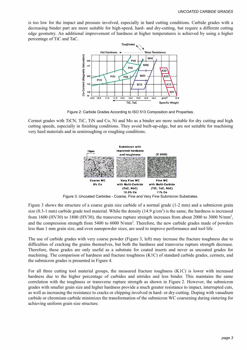
Figure 3: Uncoated Carbides - Coarse, Fine and Very Fine Submicron Substrates.
Figure 3 shows the structure of a coarse grain size carbide of a normal grade (1-2 mm) and a submicron grainsize (0.3-1 mm) carbide grade tool material. While the density (14.9 g/cm3) is the same, the hardness is increasedfrom 1600 (HV30) to 1800 (HV30), the transverse rupture strength increases from about 2000 to 3000 N/mm2,and the compression strength from 5400 to 6000 N/mm2. Therefore, the new carbide grades made of powdersless than 1 mm grain size, and even nanopowder sizes, are used to improve performance and tool life.
The use of carbide grades with very coarse powder (Figure 3, left) may increase the fracture toughness due todifficulties of cracking the grains themselves, but both the hardness and transverse rupture strength decrease.Therefore, these grades are only useful as a substrate for coated inserts and never as uncoated grades formachining. The comparison of hardness and fracture toughness (K1C) of standard carbide grades, cermets, andthe submicron grades is presented in Figure 4.
For all three cutting tool material groups, the measured fracture toughness (K1C) is lower with increasedhardness due to the higher percentage of carbides and nitrides and less binder. This maintains the samecorrelation with the toughness or transverse rupture strength as shown in Figure 2. However, the submicrongrades with smaller grain size and higher hardness provide a much greater resistance to impact, interrupted cuts,as well as increasing the resistance to cracks or chipping involved in hard- or dry-cutting. Doping with vanadiumcarbide or chromium carbide minimizes the transformation of the submicron WC coarsening during sintering forachieving uniform grain size structure.
page 3

DEVELOPMENT AND APPLICATION OF NEW CUTTING TOOL MATERIALS
Figure 4: Fracture Toughness and Hardness of Cermets, Standard ISO Grades and Submicron Carbides.
Cermets with higher hardness and good resistance to built-up edge are used only for finishing and semifinishingdue to the lower fracture toughness and sharp cutting edges. Uncoated (or coated) cermets could berecommended for dry cutting at medium-speed machining, but only at low forces and lower machiningconditions, which means small feeds and small depths of cut.
3 PVD AND CVD COATINGS
The latest developments and industrial implementation of cutting tool materials can be found in the area ofcoating technology, namely the PVD coated carbide tools as shown in Figure 5.
When using standard CVD process, furnace temperature is about 1000°C and the pressure is relatively high. Inthis CVD process a relatively thick layer is produced (2 to 20 µm) made of various thickness and materialcombinations of carbides, nitrides and oxides. Each one of these layers provides good properties with respect toeither hardness, heat conductivity, toughness or adherence to the substrate. The coating sequence depends on thevarious properties of each material. In comparison, as shown in Figure 5, the PVD process is done at relativelylow temperature of between 400° to 700°C and produces thin nitride layers made of TiN, TiCN or TiAlN.
Figure 5: Pressure Temperature Zones during PVD and CVD Coating.
Currently, only nitrides with a thickness between 3 to 6 µm can be produced by this physical vapor depositionprocess. However, a wide range of new substrates could be coated successfully by the PVD process. Forexample, thin CrN layers are used today for machining titanium or titanium di-boride layers for machiningaluminum due to minimizing the built-up-edge effect. A promising development in PVD coating is the use oflubricating top layers for lowering the friction coefficient and forces acting between the workpiece, the chips andthe cutting edge clearance, and rake surfaces accordingly. Different materials, such as MoS2 with or withoutmetallic layers, diamond-like carbon (DLC), or tungsten carbide with carbon (WC+C) are used successfully.These materials, coated as thin layers by PVD technology, react with the workpiece and the chips to improve thechip flow in deep drilling and reduce drilling forces, among other effects. The main advantage is the lubricatingeffect in machining materials with high affinity of sticking and/or build-up tendency, such as stainless steel andother nonferrous materials.
page 4

PVD AND CVD COATINGS
Coating thicknesses of PVD and CVD processes have a significant influence on the transverse rupture strength(TRS) as shown in Figure 6. For example, it can be seen from the results that using a 10 µm layer instead of 5µm layer may cause a 10 to 25% reduction in rupture strength.
Figure 6: Cutting Tool Material Strength of PVD and CVD Coatings.
Without special treatment or changes of substrate composition, bending strength values always decrease whenthe substrate is coated, primarily due to the CVD process.
The PVD process in comparison to the CVD has almost no influence on the TRS strength of the coated materialand is almost the same as the strength of substrate. Using the standard CVD process can cause a 30% reductionof strength which can be improved by using the moderate temperature process (MT) at 850°C coatingtemperature shown in Figure 5. Due to lower material expansion, the stresses in 850°C decrease in comparisonto 1100°C, and toughness is significantly improved. Reducing the TiCN coating temperature to 850-900°Celiminates the chemical reaction between the deposition reactive gases and the hardmetal surface resulting ingood adherence of the coating without the brittle eta phase nucleation that occurs during the WC+Cotransformation process. The TiCN grains show a elongated fine columnar structure with preferred crystalorientation growth perpendicular to the friction force direction, improving flank wear behavior.
Figure 7: Vickers hardness of various coating-layer compositions.
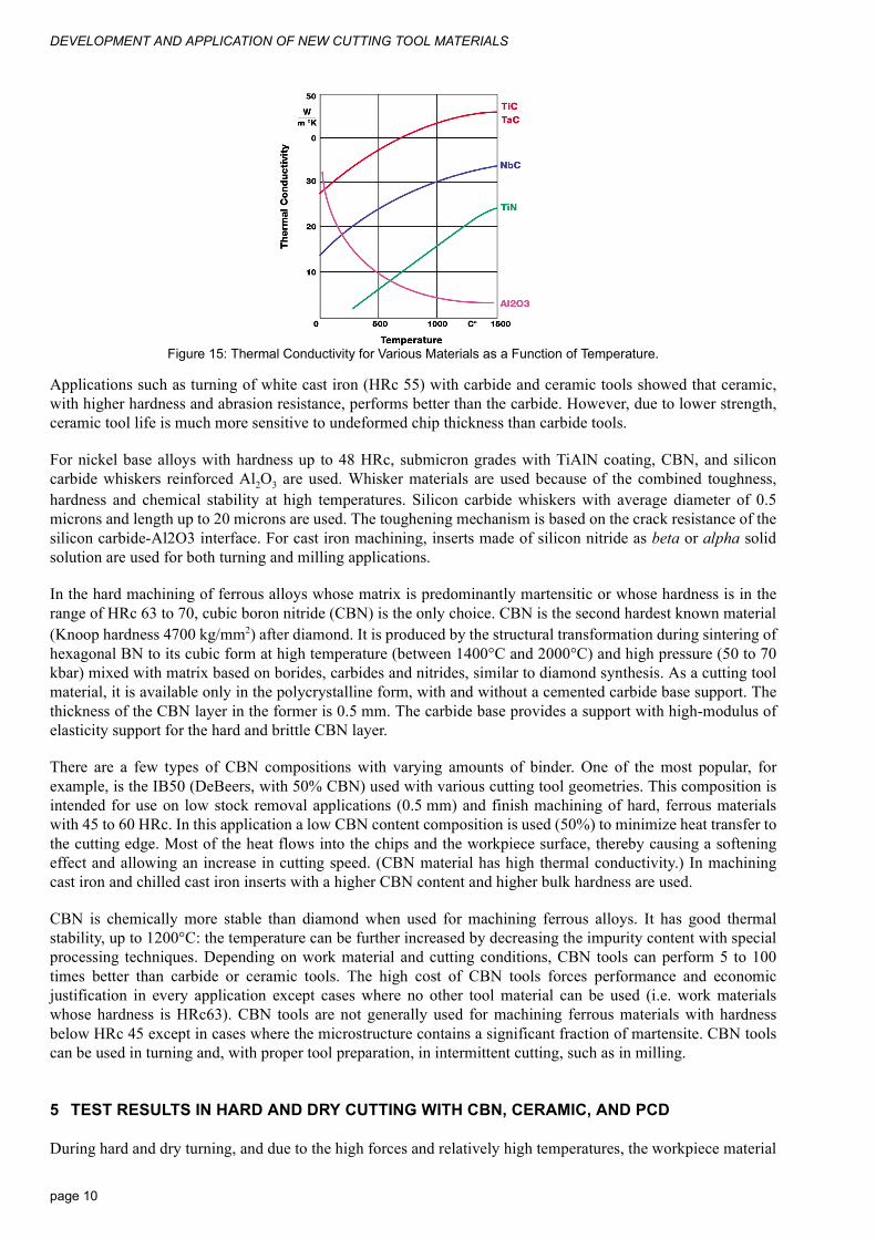
The hardness of the various coated layers in comparison with the substrate is shown in Figure 7. The hardness ofTiC is the highest, TiAlN and TiCN are very high, reaching between 2500 to 3000 HV hardness, while all otherlayers are lower. Other important advantages of the various coating layers are shown in Figure 8. The TiC layerwith the highest hardness improves resistance to mechanical wear. The disadvantage of TiC is the lowerchemical stability and higher friction coefficient. The use of ceramic coating (Al2O3) improves chemicalstability, while the nitride coatings such as TiN and ZrN reduce friction forces due to the lower frictioncoefficient. The most effective average properties can be achieved by the TiAlN and TiCN upper layers.
4000
3000
2000
1000
rdne
ss H
V0.0
5
Gre
y
True
-Pur
ple
Bro
wn/
Viol
et
Gol
den
Yello
w
Bla
ck
Brig
ht-Y
ello
w
Gre
y
page 5
DEVELOPMENT AND APPLICATION OF NEW CUTTING TOOL MATERIALS
Figure 8: The Main Properties of Various Coating Layers.
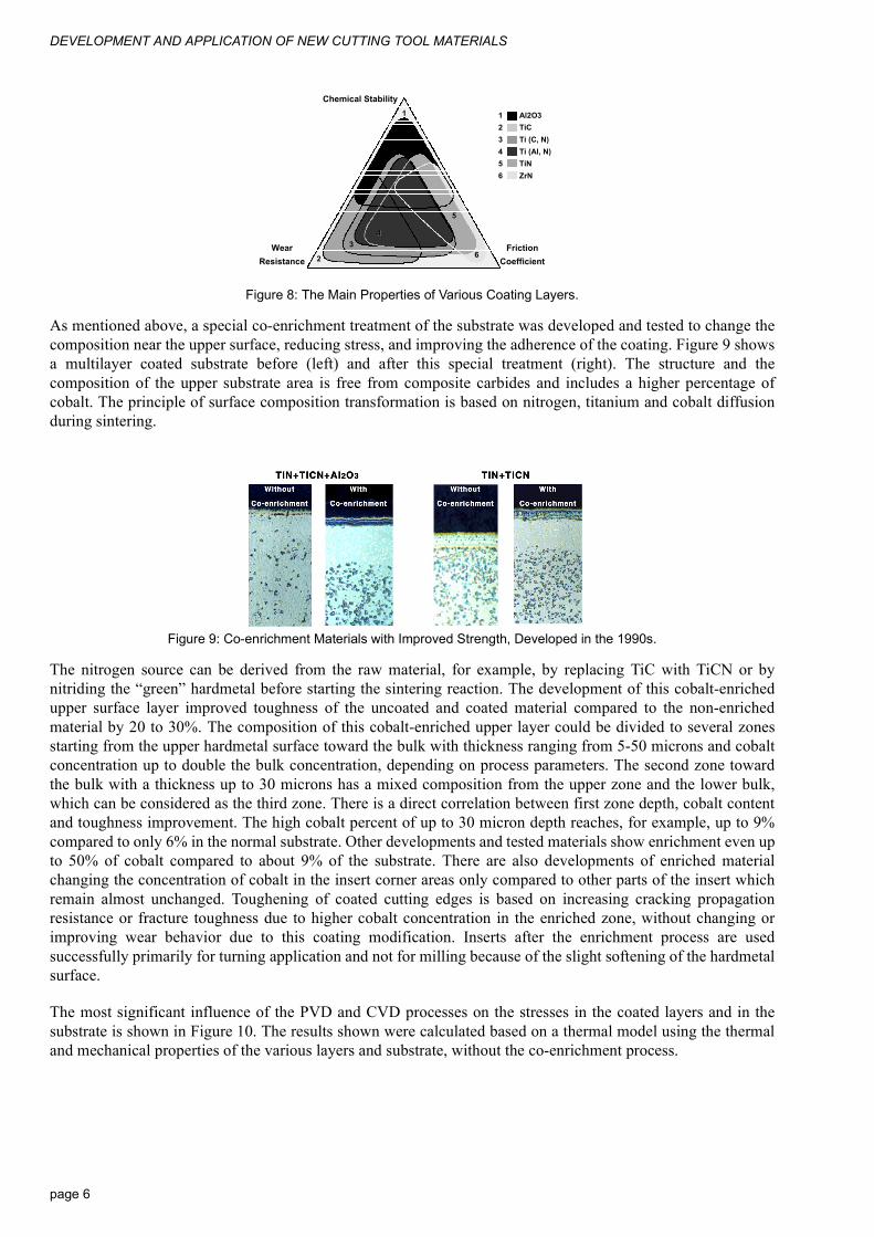
As mentioned above, a special co-enrichment treatment of the substrate was developed and tested to change thecomposition near the upper surface, reducing stress, and improving the adherence of the coating. Figure 9 showsa multilayer coated substrate before (left) and after this special treatment (right). The structure and thecomposition of the upper substrate area is free from composite carbides and includes a higher percentage ofcobalt. The principle of surface composition transformation is based on nitrogen, titanium and cobalt diffusionduring sintering.
Figure 9: Co-enrichment Materials with Improved Strength, Developed in the 1990s.
The nitrogen source can be derived from the raw material, for example, by replacing TiC with TiCN or bynitriding the “green” hardmetal before starting the sintering reaction. The development of this cobalt-enrichedupper surface layer improved toughness of the uncoated and coated material compared to the non-enrichedmaterial by 20 to 30%. The composition of this cobalt-enriched upper layer could be divided to several zonesstarting from the upper hardmetal surface toward the bulk with thickness ranging from 5-50 microns and cobaltconcentration up to double the bulk concentration, depending on process parameters. The second zone towardthe bulk with a thickness up to 30 microns has a mixed composition from the upper zone and the lower bulk,which can be considered as the third zone. There is a direct correlation between first zone depth, cobalt contentand toughness improvement. The high cobalt percent of up to 30 micron depth reaches, for example, up to 9%compared to only 6% in the normal substrate. Other developments and tested materials show enrichment even upto 50% of cobalt compared to about 9% of the substrate. There are also developments of enriched materialchanging the concentration of cobalt in the insert corner areas only compared to other parts of the insert whichremain almost unchanged. Toughening of coated cutting edges is based on increasing cracking propagationresistance or fracture toughness due to higher cobalt concentration in the enriched zone, without changing orimproving wear behavior due to this coating modification. Inserts after the enrichment process are usedsuccessfully primarily for turning application and not for milling because of the slight softening of the hardmetalsurface.
The most significant influence of the PVD and CVD processes on the stresses in the coated layers and in thesubstrate is shown in Figure 10. The results shown were calculated based on a thermal model using the thermaland mechanical properties of the various layers and substrate, without the co-enrichment process.
Chemical Stability
FrictionCoefficient
WearResistance
Al2O3TiCTi (C, N)Ti (Al, N)TiNZrN
123456
1
2
344
55
66
page 6
PVD AND CVD COATINGS
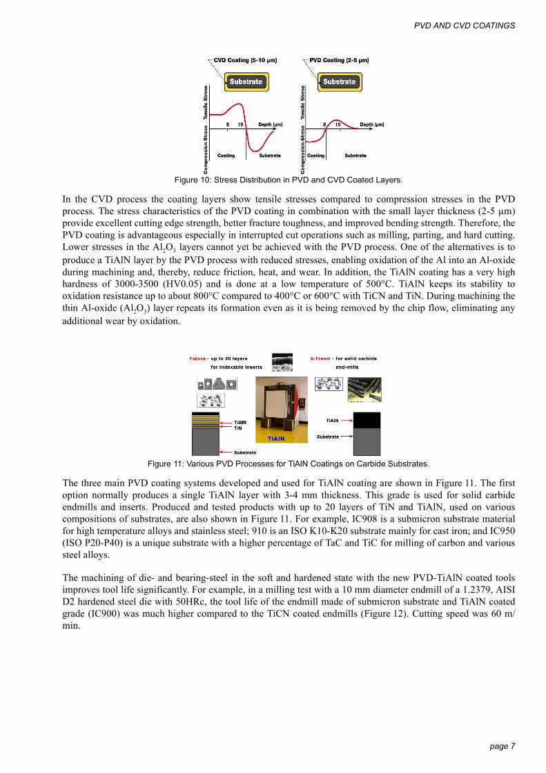
Figure 10: Stress Distribution in PVD and CVD Coated Layers.
In the CVD process the coating layers show tensile stresses compared to compression stresses in the PVDprocess. The stress characteristics of the PVD coating in combination with the small layer thickness (2-5 µm)provide excellent cutting edge strength, better fracture toughness, and improved bending strength. Therefore, thePVD coating is advantageous especially in interrupted cut operations such as milling, parting, and hard cutting.Lower stresses in the Al2O3 layers cannot yet be achieved with the PVD process. One of the alternatives is toproduce a TiAlN layer by the PVD process with reduced stresses, enabling oxidation of the Al into an Al-oxideduring machining and, thereby, reduce friction, heat, and wear. In addition, the TiAlN coating has a very highhardness of 3000-3500 (HV0.05) and is done at a low temperature of 500°C. TiAlN keeps its stability tooxidation resistance up to about 800°C compared to 400°C or 600°C with TiCN and TiN. During machining thethin Al-oxide (Al2O3) layer repeats its formation even as it is being removed by the chip flow, eliminating anyadditional wear by oxidation.
Figure 11: Various PVD Processes for TiAlN Coatings on Carbide Substrates.
The three main PVD coating systems developed and used for TiAlN coating are shown in Figure 11. The firstoption normally produces a single TiAlN layer with 3-4 mm thickness. This grade is used for solid carbideendmills and inserts. Produced and tested products with up to 20 layers of TiN and TiAlN, used on variouscompositions of substrates, are also shown in Figure 11. For example, IC908 is a submicron substrate materialfor high temperature alloys and stainless steel; 910 is an ISO K10-K20 substrate mainly for cast iron; and IC950(ISO P20-P40) is a unique substrate with a higher percentage of TaC and TiC for milling of carbon and varioussteel alloys.
The machining of die- and bearing-steel in the soft and hardened state with the new PVD-TiAlN coated toolsimproves tool life significantly. For example, in a milling test with a 10 mm diameter endmill of a 1.2379, AISID2 hardened steel die with 50HRc, the tool life of the endmill made of submicron substrate and TiAlN coatedgrade (IC900) was much higher compared to the TiCN coated endmills (Figure 12). Cutting speed was 60 m/min.
page 7

DEVELOPMENT AND APPLICATION OF NEW CUTTING TOOL MATERIALS
Figure 12: Tool Life of Various Solid Carbide Coated Submicron Endmills.
The endmills tested possess large helix angles of 30° to 40° with reduced cutting forces and improved stability.As the frontal cutting-edge corner is subjected to higher impacts a 90° almost sharp-edged tool (EC) and a toolwith a unique chamfered edge configuration (ECC) was used. Comparison of tool life (machining time) of theEC and ECC types, both with PVD coated TiCN layer, to the ECC type with TiAlN coating, is shown in thediagram.
The tool life of the ECC TiAlN coated tool for a wear land of VB=0.2 mm was doubled compared to the EC-sharp edge type with a TiCN coated layer. In some cases, the use of sharp corners is essential due to theworkpiece configuration and, therefore, standard EC endmills are used.
As mentioned above, the oxidation of the aluminum into Al2O3 protects the substrate, improves thermal stability,eliminates or minimizes heat penetration into the tool, and keeps the substrate hardness even when at elevatedtemperatures. When using the multilayered coated material (TiN+TiCN up to 20 layers), the removal of one orseveral layers will not cause the end of tool life, and a much longer operating time can be expected.
The coating of many TiN and TiAlN layers with an overall 4-6 mm thickness and more than 3000 HV hardnessalso provides a relatively high hot hardness required in all cutting processes. The TiAlN coated carbide tools arevery successful in machining at higher cutting speeds and machining of hardened steel, and are therefore the firstcoated insert of choice for dry cutting. Superior oxidation resistance and low thermal conductivity of the Al-oxide layers are essential for these applications. The formation of the Al-oxide protective layer at hightemperature is unique for this TiAlN coating, compared to the TiN and TiCN layers, and is the main reason forthe improved tool life.
Two advanced processing techniques have been recently developed to improve the oxidation resistance and heattransfer to the cutting edge material during machining. The first technique is based on PVD coating of crystallineAl2O3 as the top layer; the second technique is based on TiAlN alloying with a low percentage of Si, Y, and otherelements.
Due to the low compression stresses and thin coated layers, the PVD process enables coated tools and insertswith relatively sharp cutting edges to be used in milling, threading, and turning at smaller feeds and smallerdepths of cut. It eliminates higher cutting edge pressures associated with the larger honed edges necessary whenthe CVD process is used.
Two examples for the developed and tested submicron grade with a TiCN+TiN PVD and TiAlN coating for hardturning are shown in Figure 13. For wetting purposes and improved bulk toughness, a chrome-carbide additive isused. The relative high hardness of the substrate reaching 1700 HV20 and high rupture strength, together withthe PVD coating layers, is recommended for hard machining at small feeds and small depths of cut, in additionto the advantages in machining high-temp alloys and stainless steel. The TiAlN coated grade (IC907) is excellentfor dry cutting, hard cutting and high-speed machining applications.
page 8

NEW OXIDE, NITRIDE, AND CERAMIC MATERIALS
Figure 13: Submicron Substrate and PVD Coated TiCN+TiN and TiAlN Grades.
In dry milling of cast iron and some steel compositions, the MT-CVD (moderate temperature TiCN coating)coated grades with Al2O3 coating were found to be very useful. The combination of a tough substrate and thecoating provides an option for relatively-high cutting speeds. The induced tensile stresses in the CVD coatedlayers described above limit the machining conditions, especially for very high impacts. While cermet has a verylow toughness and, therefore, is used only in finishing and semifinishing, the new MT-CVD was found to bemore suitable for finishing and semifinishing under higher impact conditions. The main features and advantagesof the MT-CVD coated grades are shown in Figure 14.
Figure 14: Structure and Properties of Substrate and Basic MT-CVD Layers.
The sequence of coated layers can be optimized to resist heat conduction into the substrate with the Al2O3 layer,to reduce friction with the TiN layer and to reduce flank wear by using a TiCN layer. There is, of course, a limitof temperature, friction, heat, and load that can be used on a CVD coated insert.
Figure 5 shows the development of CVD, characterized today by the use of MT-CVD to improve toughness.This in addition to using the Co enriched upper substrate layer by using the special enrichment process. TheCVD grades enriched with cobalt can be coated with various layer combinations depending on the applicationrange.
The successful use of ceramic coatings (Al2O3) can be explained by the heat conductivity as a function oftemperature (Figure 15). While heat conductivity increases with temperature for all coated layers, the values forceramics (Al2O3) decrease significantly with higher speeds or higher temperatures, as shown in Figure 15.
4 NEW OXIDE, NITRIDE, AND CERAMIC MATERIALS
Ceramic tools are generally used for high-cutting speed, finish-machining of ferrous alloys or machining ofvarious cast iron workpieces. They can, however, also be used successfully for machining very hard materialswith hardness up to HRc 63, but at lower or medium cutting speed and on extremely rigid machine tools.Aluminum oxide with up to 40% TiC, and alternatively with up to 30% ZrO2, are two popular ceramic toolmaterials. Pure aluminum oxide, while very hard, is also brittle. Alloying it with TiC and/or ZrO2 increases itstoughness, stability, and thermal conductivity without seriously compromising hardness.
page 9
DEVELOPMENT AND APPLICATION OF NEW CUTTING TOOL MATERIALS
Figure 15: Thermal Conductivity for Various Materials as a Function of Temperature.
Applications such as turning of white cast iron (HRc 55) with carbide and ceramic tools showed that ceramic,with higher hardness and abrasion resistance, performs better than the carbide. However, due to lower strength,ceramic tool life is much more sensitive to undeformed chip thickness than carbide tools.
For nickel base alloys with hardness up to 48 HRc, submicron grades with TiAlN coating, CBN, and siliconcarbide whiskers reinforced Al2O3 are used. Whisker materials are used because of the combined toughness,hardness and chemical stability at high temperatures. Silicon carbide whiskers with average diameter of 0.5microns and length up to 20 microns are used. The toughening mechanism is based on the crack resistance of thesilicon carbide-Al2O3 interface. For cast iron machining, inserts made of silicon nitride as beta or alpha solidsolution are used for both turning and milling applications.
In the hard machining of ferrous alloys whose matrix is predominantly martensitic or whose hardness is in therange of HRc 63 to 70, cubic boron nitride (CBN) is the only choice. CBN is the second hardest known material(Knoop hardness 4700 kg/mm2) after diamond. It is produced by the structural transformation during sintering ofhexagonal BN to its cubic form at high temperature (between 1400°C and 2000°C) and high pressure (50 to 70kbar) mixed with matrix based on borides, carbides and nitrides, similar to diamond synthesis. As a cutting toolmaterial, it is available only in the polycrystalline form, with and without a cemented carbide base support. Thethickness of the CBN layer in the former is 0.5 mm. The carbide base provides a support with high-modulus ofelasticity support for the hard and brittle CBN layer.
There are a few types of CBN compositions with varying amounts of binder. One of the most popular, forexample, is the IB50 (DeBeers, with 50% CBN) used with various cutting tool geometries. This composition isintended for use on low stock removal applications (0.5 mm) and finish machining of hard, ferrous materialswith 45 to 60 HRc. In this application a low CBN content composition is used (50%) to minimize heat transfer tothe cutting edge. Most of the heat flows into the chips and the workpiece surface, thereby causing a softeningeffect and allowing an increase in cutting speed. (CBN material has high thermal conductivity.) In machiningcast iron and chilled cast iron inserts with a higher CBN content and higher bulk hardness are used.
CBN is chemically more stable than diamond when used for machining ferrous alloys. It has good thermalstability, up to 1200°C: the temperature can be further increased by decreasing the impurity content with specialprocessing techniques. Depending on work material and cutting conditions, CBN tools can perform 5 to 100times better than carbide or ceramic tools. The high cost of CBN tools forces performance and economicjustification in every application except cases where no other tool material can be used (i.e. work materialswhose hardness is HRc63). CBN tools are not generally used for machining ferrous materials with hardnessbelow HRc 45 except in cases where the microstructure contains a significant fraction of martensite. CBN toolscan be used in turning and, with proper tool preparation, in intermittent cutting, such as in milling.
5 TEST RESULTS IN HARD AND DRY CUTTING WITH CBN, CERAMIC, AND PCD
During hard and dry turning, and due to the high forces and relatively high temperatures, the workpiece material
page 10
TEST RESULTS IN HARD AND DRY CUTTING WITH CBN, CERAMIC, AND PCD
is deformed into chips mainly by shearing, while the machined workpiece upper surface layer is heated,softened, and cooled again. Due to these phenomena, softening phenomena, and the fast cooling effect, a whitelayer appears which is similar to the martensitic transformation phenomena occurring during EDM or heavy-duty grinding.
This unique result in hard turning is studied today in order to evaluate the life of hard-turned bearing ringscompared to those produced by grinding. First results seem to indicate that the life of the machined part isidentical, and, therefore, the machining can be done by the hard turning process for all similar parts. Thedifference in hardness between the white layer and the layer directly below it is about 30-40% when drymachined with solid ceramic inserts.[2]
Hard and dry cutting are already used in a growing range of industrial applications. The widest range ofapplications for both methods can be found in the automotive industry.
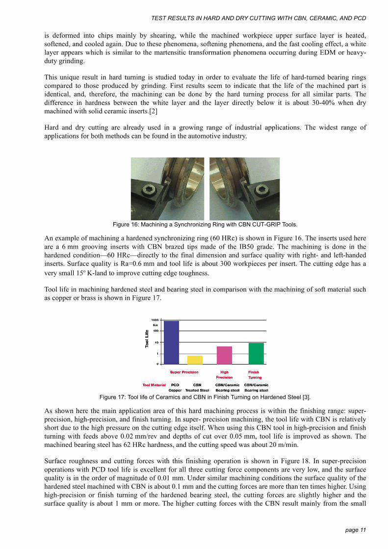
Figure 16: Machining a Synchronizing Ring with CBN CUT-GRIP Tools.
An example of machining a hardened synchronizing ring (60 HRc) is shown in Figure 16. The inserts used hereare a 6 mm grooving inserts with CBN brazed tips made of the IB50 grade. The machining is done in thehardened condition—60 HRc—directly to the final dimension and surface quality with right- and left-handedinserts. Surface quality is Ra=0.6 mm and tool life is about 300 workpieces per insert. The cutting edge has avery small 15o K-land to improve cutting edge toughness.
Tool life in machining hardened steel and bearing steel in comparison with the machining of soft material suchas copper or brass is shown in Figure 17.
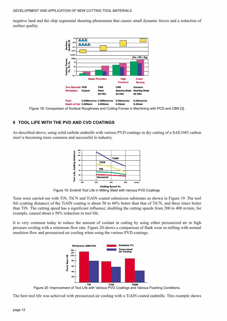
Figure 17: Tool life of Ceramics and CBN in Finish Turning on Hardened Steel [3].
As shown here the main application area of this hard machining process is within the finishing range: super-precision, high-precision, and finish turning. In super- precision machining, the tool life with CBN is relativelyshort due to the high pressure on the cutting edge itself. When using this CBN tool in high-precision and finishturning with feeds above 0.02 mm/rev and depths of cut over 0.05 mm, tool life is improved as shown. Themachined bearing steel has 62 HRc hardness, and the cutting speed was about 20 m/min.
Surface roughness and cutting forces with this finishing operation is shown in Figure 18. In super-precisionoperations with PCD tool life is excellent for all three cutting force components are very low, and the surfacequality is in the order of magnitude of 0.01 mm. Under similar machining conditions the surface quality of thehardened steel machined with CBN is about 0.1 mm and the cutting forces are more than ten times higher. Usinghigh-precision or finish turning of the hardened bearing steel, the cutting forces are slightly higher and thesurface quality is about 1 mm or more. The higher cutting forces with the CBN result mainly from the small
page 11
DEVELOPMENT AND APPLICATION OF NEW CUTTING TOOL MATERIALS
negative land and the chip segmental shearing phenomena that causes small dynamic forces and a reduction ofsurface quality.
Figure 18: Comparison of Surface Roughness and Cutting Forces in Machining with PCD and CBN [3].
6 TOOL LIFE WITH THE PVD AND CVD COATINGS
As described above, using solid carbide endmills with various PVD coatings in dry cutting of a SAE1045 carbonsteel is becoming more common and successful in industry.
Figure 19: Endmill Tool Life in Milling Steel with Various PVD Coatings.
Tests were carried out with TiN, TiCN and TiAlN coated submicron substrates as shown in Figure 19. The toollife (cutting distance) of the TiAlN coating is about 50 to 60% better than that of TiCN, and three times betterthan TiN. The cutting speed has a significant influence; doubling the cutting speeds from 200 to 400 m/min, forexample, caused about a 50% reduction in tool life.
It is very common today to reduce the amount of coolant in cutting by using either pressurized air or highpressure cooling with a minimum flow rate. Figure 20 shows a comparison of flank wear in milling with normalemulsion flow and pressurized air cooling when using the various PVD coatings.
Figure 20: Improvement of Tool Life with Various PVD Coatings and Various Flushing Conditions.
The best tool life was achieved with pressurized air cooling with a TiAlN coated endmills. This example shows
page 12

References
that one of the tendencies today in metal cutting is not to eliminate the coolant completely, but rather to reducethe flow rate to a minimum or to use high air pressure.
During tests in face milling of stainless steel and Inconel 718 with square and positive rake inserts made with aTiCN-PVD coated layer having a special rake-face, rib or depression chipformer design, a significantimprovement was achieved compared to the flat design without the rib configuration (Figure 21).
Figure 21: Improved Tool Life in Milling Stainless Steel and Inconel 718 with TiCN Coated Inserts.
The tool life achieved with a PVD-TiCN coated insert (IC328) was about 50% better than a CVD coated tool.When using the flat rake-face (the -42 design) tool life in machining stainless with the PVD coated IC328 was 20minutes. Using a depression type rake-face (the -76 design) the tool life was 50% higher. When using 80 m/mininstead of 120 m/min, the tool life reached 50 minutes. The same phenomena could be observed whenmachining Inconel 718—an improvement of tool life by more than 50% with the depression type chipformercompared to the flat type. This shows clearly the advantage of reducing contact area between chip and rake face,friction and heat transfer to the insert in combination with the TiCN coated layer.
7 REFERENCES
[1] R. Wertheim "Development and Application of New Cutting Tool Materials" CIRP General Assembly, Montreux,Switzerland, August 1999.
[2] H. K.Toenshoff, C. Arendt, R. Ben Amor "Cutting Hardened Steel" Annals of CIRP Vol. 49/2/2000 Pages 1-19.[3] W. Koening, Report by WZL, T. H. Aachen, 1994.
page 13
Related Documents