Chapter 21 Cutting-Tool Materials and Cutting Fluids

Chapter 21 Cutting-Tool Materials and Cutting Fluids.
Dec 28, 2015
Welcome message from author
This document is posted to help you gain knowledge. Please leave a comment to let me know what you think about it! Share it to your friends and learn new things together.
Transcript
Chapter 21Cutting-Tool Materials and Cutting
Fluids
IntroductionIntroduction
• Cutting Tool Characteristics:Cutting Tool Characteristics:
1. Maintaining hardness, strength, and wear resistance at elevated temperatures. This property ensures that the tool does not undergo any plastic deformation and thus retains its shape and sharpness.
2. Toughness and impact strength (or mechanical shock resistance), so that impact forces on the tool that are encountered repeatedly in interrupted cutting operations or forces due to vibration and chatter during machining do not chip or fracture the tool.
3. Thermal Shock resistance to withstand the rapid temperature cycling encountered in interrupted cutting.
4. Wear resistance so that an acceptable tool life is obtained before replacement is necessary.
5. Chemical stability to avoid or minimize any adverse reactions, adhesion, and tool-chip diffusion.
• Tool Materials Categories:Tool Materials Categories:
1. High-speed steels
2. Cast-cobalt alloys
3. Carbides
4. Coated tools
5. Alumina-based ceramics
6. Cubic boron nitride
7. Silicon-nitride-base ceramics
8. Diamond
9. Whisker-reinforced materials
IntroductionIntroduction
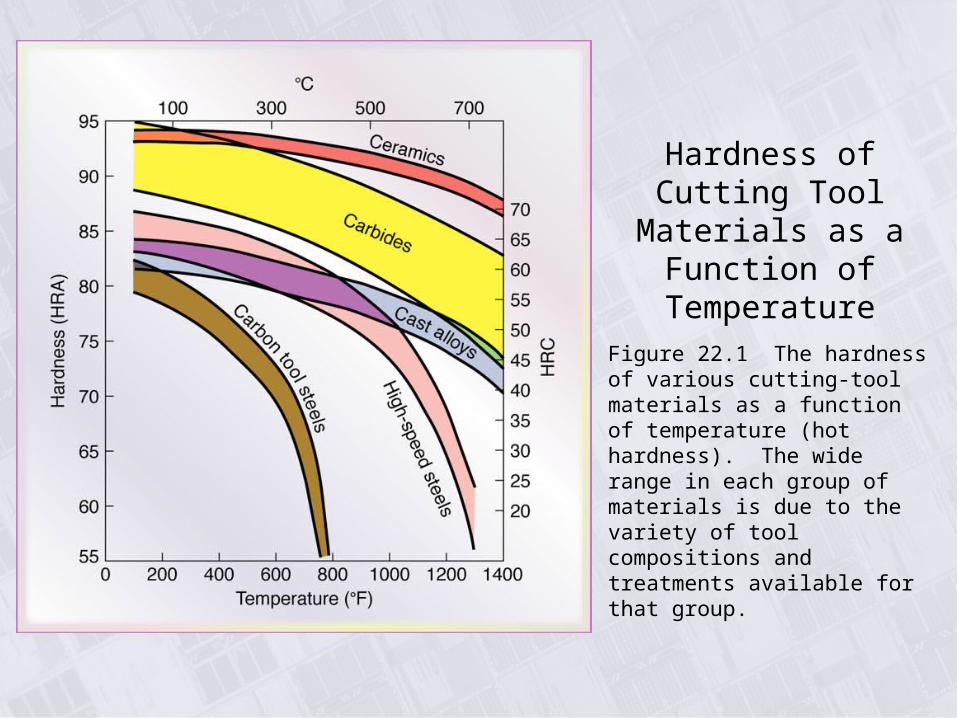
Hardness of Cutting Tool Materials as a
Function of Temperature
Figure 22.1 The hardness of various cutting-tool materials as a function of temperature (hot hardness). The wide range in each group of materials is due to the variety of tool compositions and treatments available for that group.
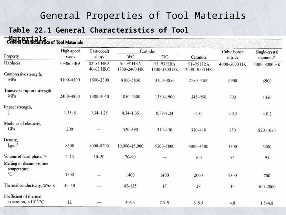
General Properties of Tool Materials
Table 22.1 General Characteristics of Tool Materials
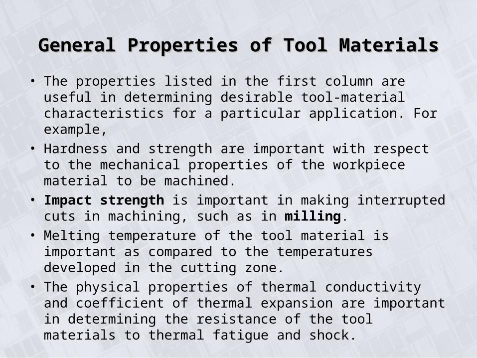
• The properties listed in the first column are useful in determining desirable tool-material characteristics for a particular application. For example,
• Hardness and strength are important with respect to the mechanical properties of the workpiece material to be machined.
• Impact strength is important in making interrupted cuts in machining, such as in milling.
• Melting temperature of the tool material is important as compared to the temperatures developed in the cutting zone.
• The physical properties of thermal conductivity and coefficient of thermal expansion are important in determining the resistance of the tool materials to thermal fatigue and shock.
General Properties of Tool MaterialsGeneral Properties of Tool Materials
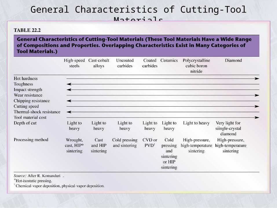
General Characteristics of Cutting-Tool Materials
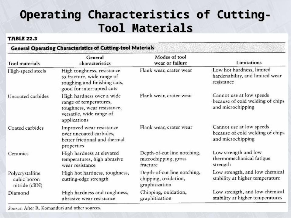
Operating Characteristics of Cutting-Tool MaterialsOperating Characteristics of Cutting-Tool Materials
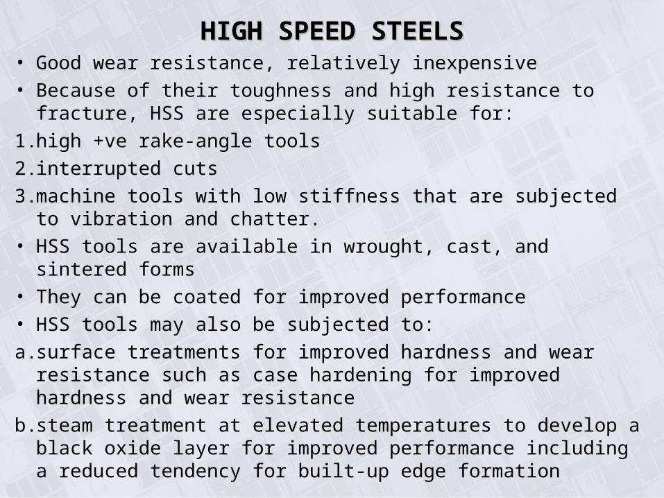
HIGH SPEED STEELSHIGH SPEED STEELS• Good wear resistance, relatively inexpensive
• Because of their toughness and high resistance to fracture, HSS are especially suitable for:
1. high +ve rake-angle tools
2. interrupted cuts
3. machine tools with low stiffness that are subjected to vibration and chatter.
• HSS tools are available in wrought, cast, and sintered forms
• They can be coated for improved performance
• HSS tools may also be subjected to:
a. surface treatments for improved hardness and wear resistance such as case hardening for improved hardness and wear resistance
b. steam treatment at elevated temperatures to develop a black oxide layer for improved performance including a reduced tendency for built-up edge formation
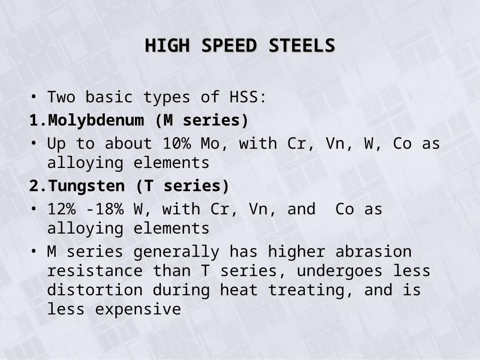
• Two basic types of HSS:
1. Molybdenum (M series)
• Up to about 10% Mo, with Cr, Vn, W, Co as alloying elements
2. Tungsten (T series)
• 12% -18% W, with Cr, Vn, and Co as alloying elements
• M series generally has higher abrasion resistance than T series, undergoes less distortion during heat treating, and is less expensive
HIGH SPEED STEELSHIGH SPEED STEELS
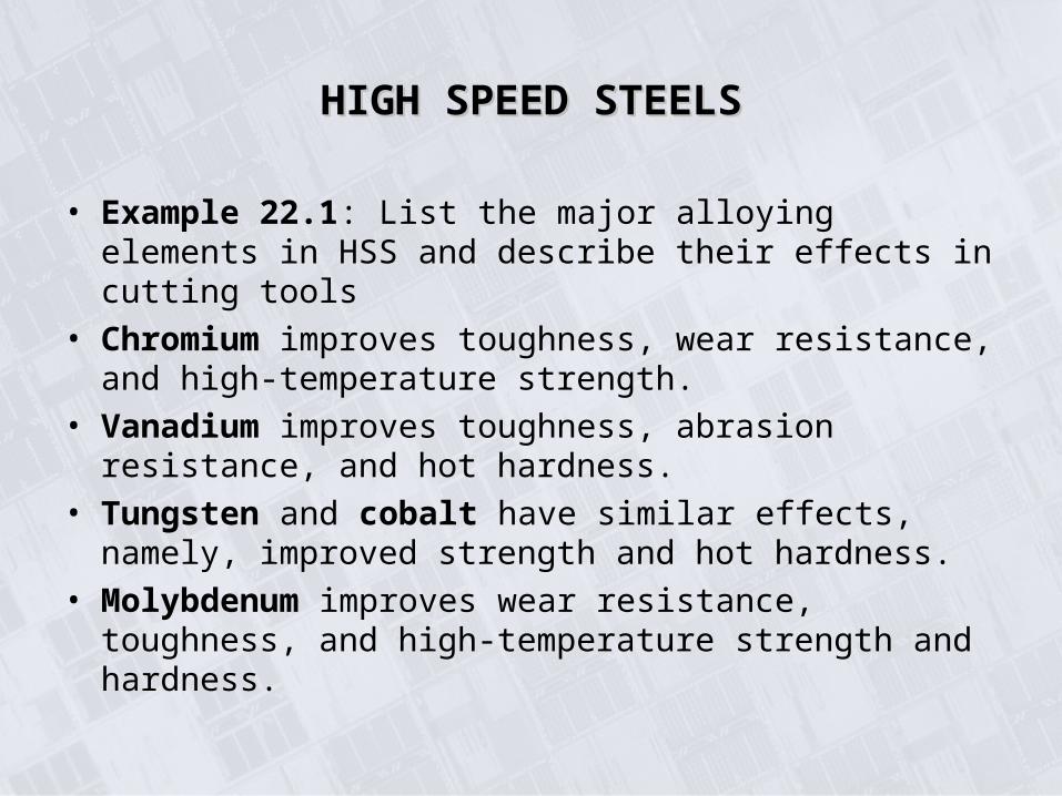
• Example 22.1: List the major alloying elements in HSS and describe their effects in cutting tools
• Chromium improves toughness, wear resistance, and high-temperature strength.
• Vanadium improves toughness, abrasion resistance, and hot hardness.
• Tungsten and cobalt have similar effects, namely, improved strength and hot hardness.
• Molybdenum improves wear resistance, toughness, and high-temperature strength and hardness.
HIGH SPEED STEELSHIGH SPEED STEELS
CAST-COBALT ALLOYSCAST-COBALT ALLOYS
• 38%-53% Co, 30%-33% Cr, and 10%-20%W
• High hardness, good wear resistance, can maintain their hardness at elevated temperatures
• They are not as tough as HSS and are sensitive to impact forces
Stellite ToolsStellite Tools
• These alloys are cast and ground into relatively simple tool shapes.
• used only for special applications that involve deep continuous roughing cuts at relatively high feeds and speeds, as much as
twice the rates possible with HSS
CARBIDESCARBIDES• The previous tools possess the required toughness, impact strength,
and thermal shock resistance, but they also have important limitations, particularly with respect to strength and hot hardness.
• Carbides have: Carbides have:
a. Hardness over a wide range of temperatures.
b. high elastic modulus and thermal conductivity.
c. low thermal expansion.
Tungsten carbide (WC):Tungsten carbide (WC):
• Composite material consisting of WC particles bonded together in a cobalt matrix
• Manufactured with powder-metallurgy techniques
• WC particles, 1-5 μm in size
• As Co content increases, the strength, hardness, and wear resistance of WC decrease, while its toughness increases because of the higher toughness of cobalt
CARBIDESCARBIDES
Titanium Carbide (TiC):
•Higher wear resistance than WC but is not as tough
•With a nickel-molybdenum alloy as the matrix, TiC is suitable for machining hard materials, mainly steels and cast irons, and for cutting at speeds higher than those for WC.
Inserts and ToolholdersInserts and Toolholders
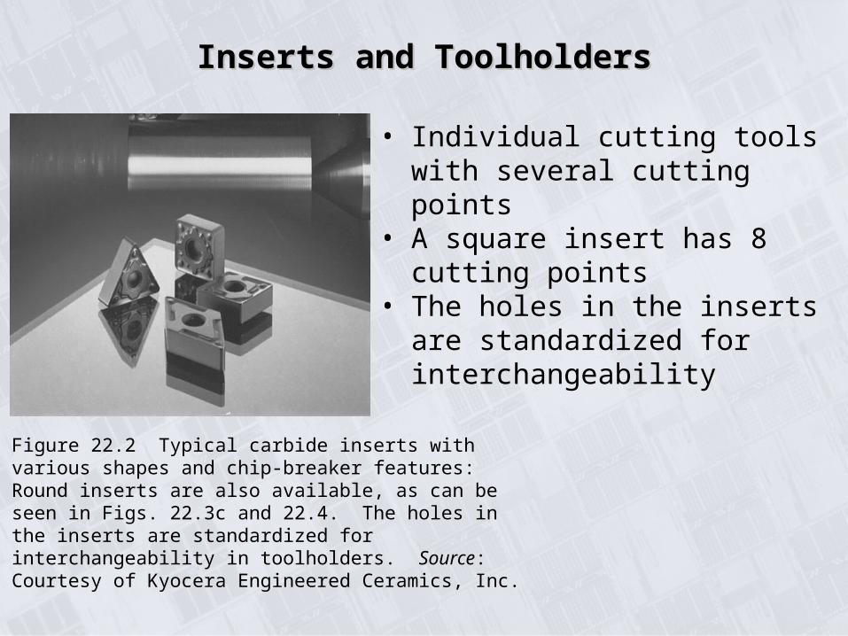
Figure 22.2 Typical carbide inserts with various shapes and chip-breaker features: Round inserts are also available, as can be seen in Figs. 22.3c and 22.4. The holes in the inserts are standardized for interchangeability in toolholders. Source: Courtesy of Kyocera Engineered Ceramics, Inc.
• Individual cutting tools with several cutting points
• A square insert has 8 cutting points• The holes in the inserts are
standardized for interchangeability
CARBIDES - Insert AttachmentCARBIDES - Insert Attachment
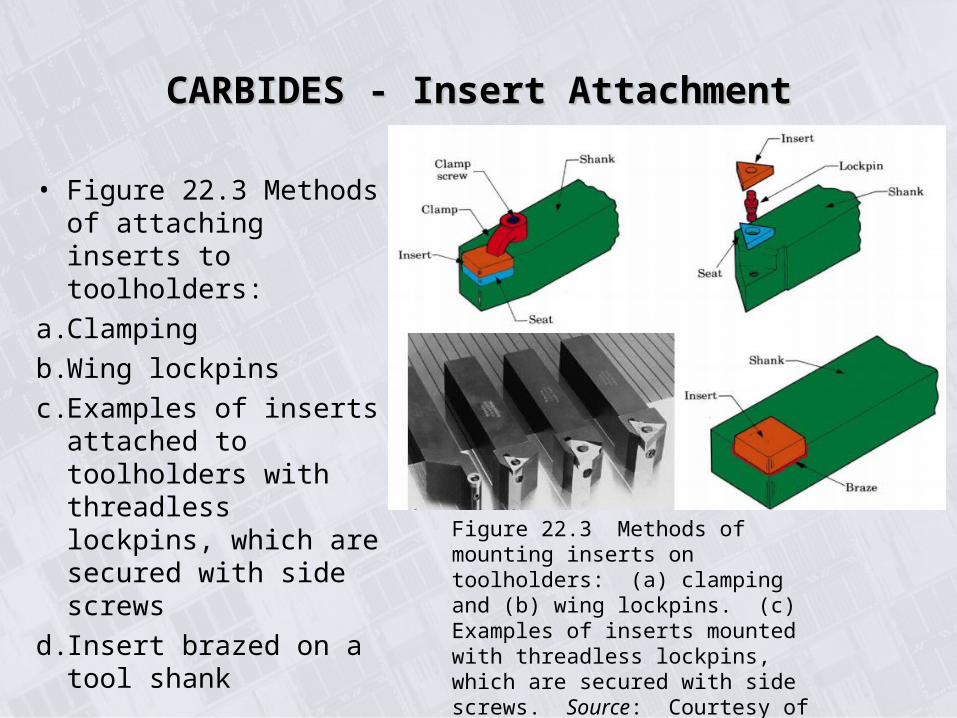
• Figure 22.3 Methods of attaching inserts to toolholders:
a. Clamping
b. Wing lockpins
c. Examples of inserts attached to toolholders with threadless lockpins, which are secured with side screws
d. Insert brazed on a tool shank
Figure 22.3 Methods of mounting inserts on toolholders: (a) clamping and (b) wing lockpins. (c) Examples of inserts mounted with threadless lockpins, which are secured with side screws. Source: Courtesy of Valenite.
Insert Edge PropertiesInsert Edge Properties
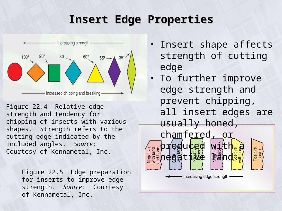
Figure 22.4 Relative edge strength and tendency for chipping of inserts with various shapes. Strength refers to the cutting edge indicated by the included angles. Source: Courtesy of Kennametal, Inc.
Figure 22.5 Edge preparation for inserts to improve edge strength. Source: Courtesy of Kennametal, Inc.
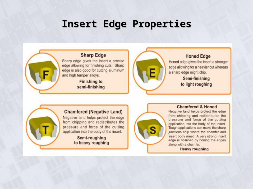
• Insert shape affects strength of cutting edge
• To further improve edge strength and prevent chipping, all insert edges are usually honed, chamfered, or produced with a negative land.
Insert Edge PropertiesInsert Edge Properties
CARBIDES – General notesCARBIDES – General notes
• Stiffness of the machine tool is of major importance when using carbide tools
• Light feeds, low speeds, and chatter are detrimental because they tend to damage the tool's cutting edge.
Light feeds, for example, concentrate the forces and temperature closer to the edges of the tool, increasing the tendency for the edges to chip off
Low cutting speeds tend to encourage cold welding of the chip to the tool
• Cutting fluids, if used to minimize heating and cooling of the tool in interrupted cutting operations, should be applied continuously and in large quantities (flood).
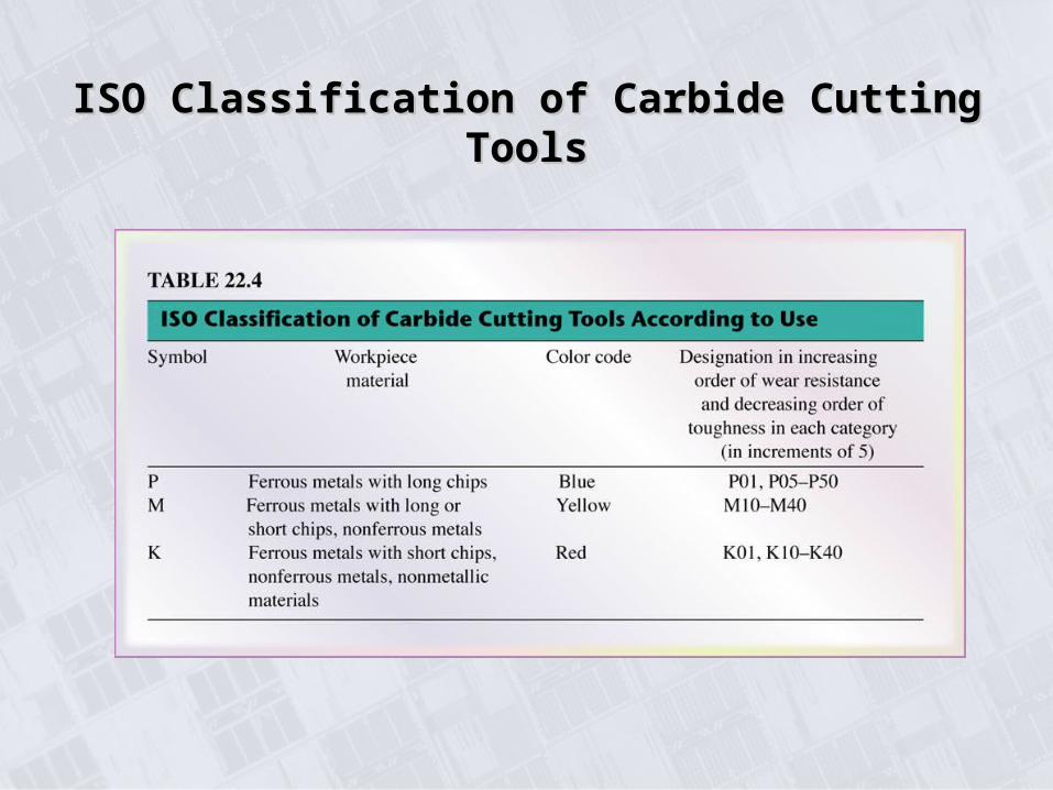
ISO Classification of Carbide Cutting ToolsISO Classification of Carbide Cutting Tools
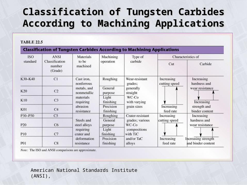
Classification of Tungsten Carbides According Classification of Tungsten Carbides According to Machining Applicationsto Machining Applications
American National Standards Institute (ANSI),
COATED TOOLSCOATED TOOLS
• Because of their unique properties, such as lower friction and higher resistance to cracks and wear, coated tools can be used at high cutting speeds, reducing both the time required for machining operations and costs.
• Coated tools can have tool lives 10 times longer than those of uncoated tools.
Relative Time Required to Machine with Various Relative Time Required to Machine with Various Cutting-Tool MaterialsCutting-Tool Materials
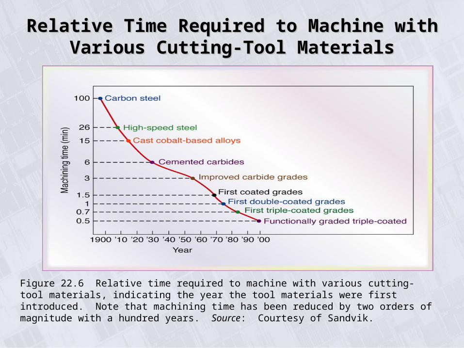
Figure 22.6 Relative time required to machine with various cutting-tool materials, indicating the year the tool materials were first introduced. Note that machining time has been reduced by two orders of magnitude with a hundred years. Source: Courtesy of Sandvik.
COATED TOOLS - Coating MaterialsCOATED TOOLS - Coating Materials
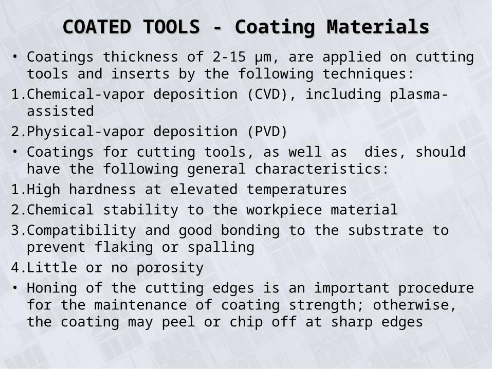
• Coatings thickness of 2-15 μm, are applied on cutting tools and inserts by the following techniques:
1. Chemical-vapor deposition (CVD), including plasma-assisted
2. Physical-vapor deposition (PVD)
• Coatings for cutting tools, as well as dies, should have the following general characteristics:
1. High hardness at elevated temperatures
2. Chemical stability to the workpiece material
3. Compatibility and good bonding to the substrate to prevent flaking or spalling
4. Little or no porosity
• Honing of the cutting edges is an important procedure for the maintenance of coating strength; otherwise, the coating may peel or chip off at sharp edges
COATED TOOLS - Coating MaterialsCOATED TOOLS - Coating Materials
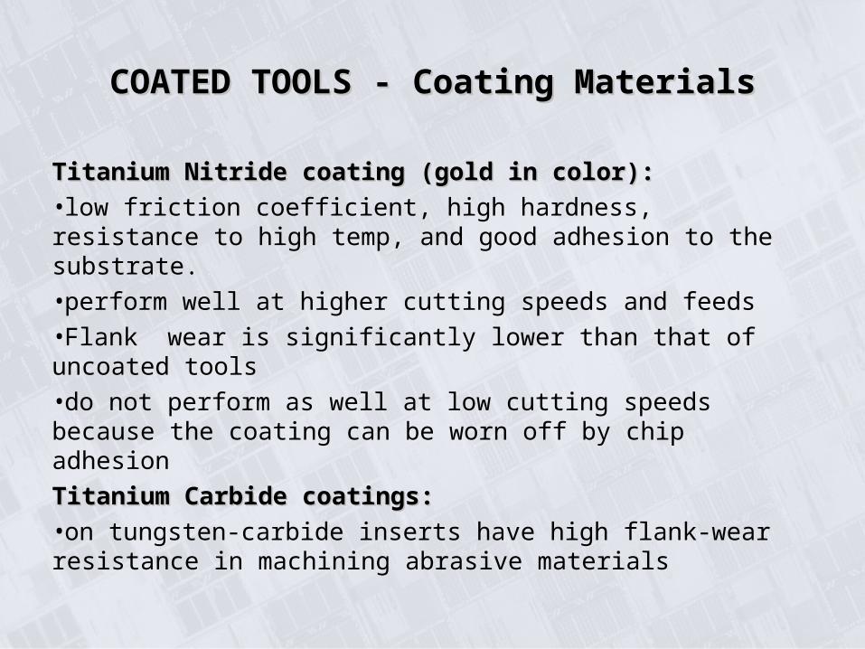
Titanium Nitride coating (gold in color):Titanium Nitride coating (gold in color):
•low friction coefficient, high hardness, resistance to high temp, and good adhesion to the substrate.
•perform well at higher cutting speeds and feeds
•Flank wear is significantly lower than that of uncoated tools
•do not perform as well at low cutting speeds because the coating can be worn off by chip adhesion
Titanium Carbide coatings:Titanium Carbide coatings:
•on tungsten-carbide inserts have high flank-wear resistance in machining abrasive materials
Typical Wear Patterns on High-Speed-Steel Typical Wear Patterns on High-Speed-Steel Uncoated and Titanium-Nitride Coated ToolsUncoated and Titanium-Nitride Coated Tools
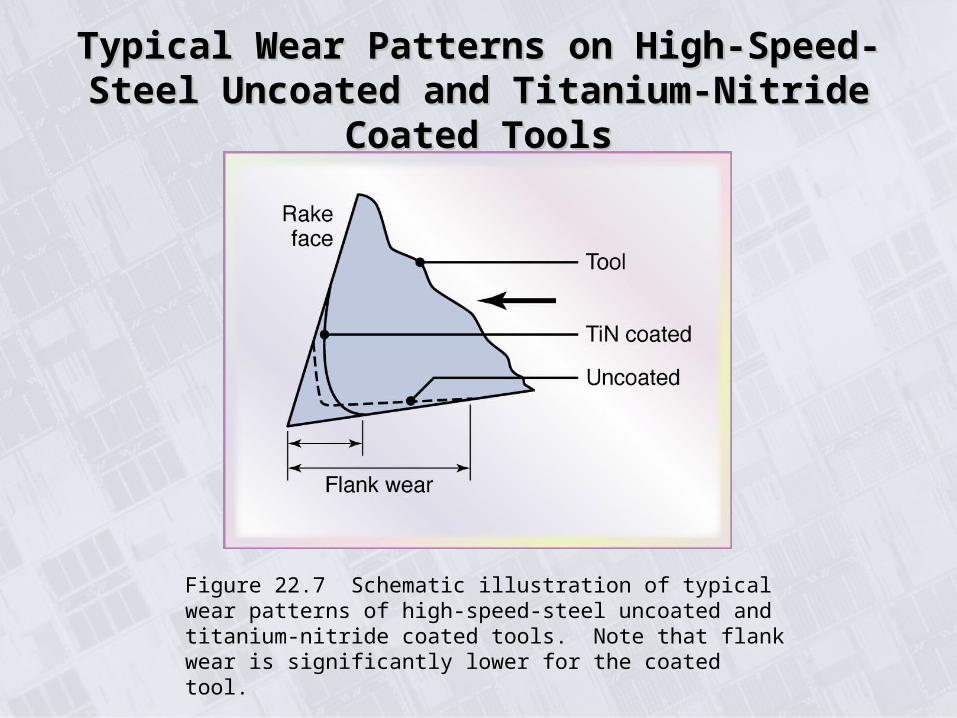
Figure 22.7 Schematic illustration of typical wear patterns of high-speed-steel uncoated and titanium-nitride coated tools. Note that flank wear is significantly lower for the coated tool.
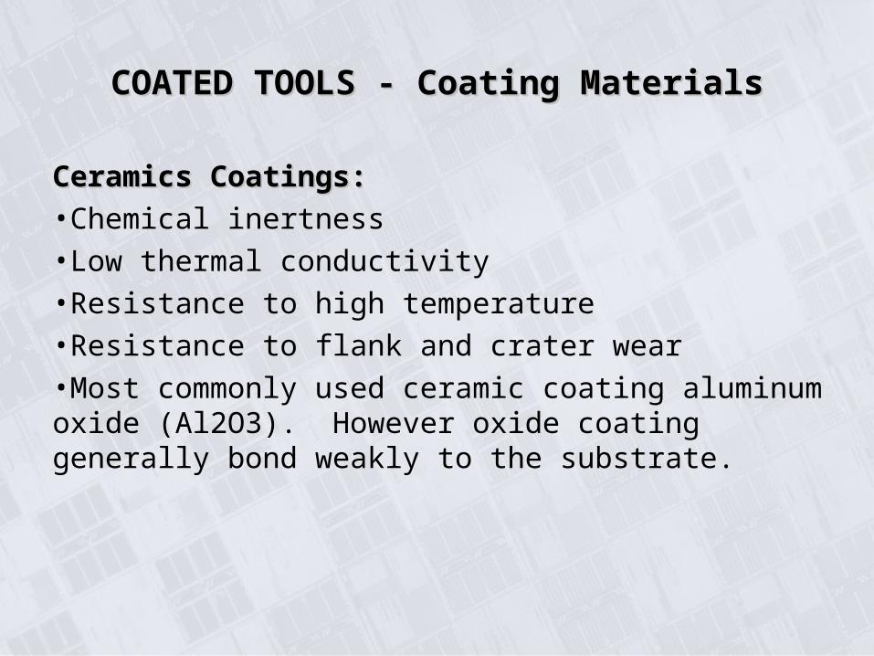
Ceramics Coatings:Ceramics Coatings:
•Chemical inertness
•Low thermal conductivity
•Resistance to high temperature
•Resistance to flank and crater wear
•Most commonly used ceramic coating aluminum oxide (Al2O3). However oxide coating generally bond weakly to the substrate.
COATED TOOLS - Coating MaterialsCOATED TOOLS - Coating Materials
COATED TOOLS - Coating MaterialsCOATED TOOLS - Coating Materials
Multiphase Coatings:Multiphase Coatings:
•Carbide tools with 2 or 3 layers of such coatings.
•Particularly effective in machining cast irons and steels.
•Typical applications of multiple-coated tools:High-speed, continuous cutting: TiC/Al2O3.Heavy-duty, continuous cutting: TiC/Al2O3/TiN.Light, interrupted cutting: TiC/TiC + TiN/TiN.
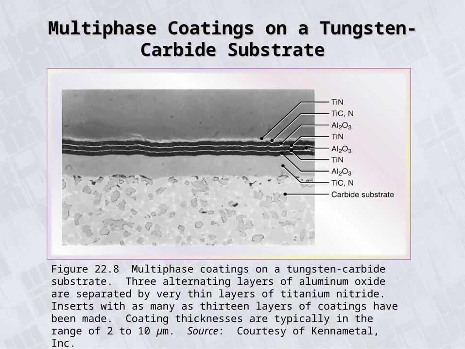
Multiphase Coatings on a Tungsten-Carbide Multiphase Coatings on a Tungsten-Carbide SubstrateSubstrate
Figure 22.8 Multiphase coatings on a tungsten-carbide substrate. Three alternating layers of aluminum oxide are separated by very thin layers of titanium nitride. Inserts with as many as thirteen layers of coatings have been made. Coating thicknesses are typically in the range of 2 to 10 μm. Source: Courtesy of Kennametal, Inc.
Multiphase Coatings:Multiphase Coatings:
Functions of coatings:
1. TiN: low friction
2. Al2O3: high thermal stability
3. TiCN: fiber reinforced with a good balance of resistance to flank and crater wear for interrupted cutting
4. A thin carbide substrate: high fracture toughness
5. A thick carbide substrate: hard and resistant to plastic deformation at high temperatures.
COATED TOOLS - Coating MaterialsCOATED TOOLS - Coating Materials
COATED TOOLS - Coating MaterialsCOATED TOOLS - Coating Materials
Diamond-Coated Tools:Diamond-Coated Tools:
•Thin films are deposited on substrates with PVD and CVD techniques.
•Thick films are obtained by growing a large sheet of pure diamond, which is then laser cut to shape and brazed to a carbide shank.
•Diamond-coated tools are particularly effective in machining nonferrous and abrasive materials, such as Al alloys containing Si, fiber-reinforced and metal-matrix composite materials, and graphite.
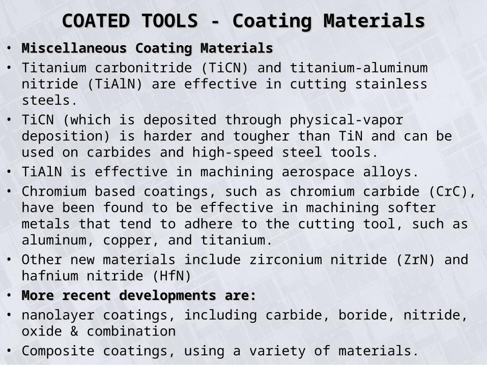
• Miscellaneous Coating MaterialsMiscellaneous Coating Materials
• Titanium carbonitride (TiCN) and titanium-aluminum nitride (TiAlN) are effective in cutting stainless steels.
• TiCN (which is deposited through physical-vapor deposition) is harder and tougher than TiN and can be used on carbides and high-speed steel tools.
• TiAlN is effective in machining aerospace alloys.
• Chromium based coatings, such as chromium carbide (CrC), have been found to be effective in machining softer metals that tend to adhere to the cutting tool, such as aluminum, copper, and titanium.
• Other new materials include zirconium nitride (ZrN) and hafnium nitride (HfN)
• More recent developments are:More recent developments are:
• nanolayer coatings, including carbide, boride, nitride, oxide & combination
• Composite coatings, using a variety of materials.
COATED TOOLS - Coating MaterialsCOATED TOOLS - Coating Materials
ALUMINA-BASED CERAMICSALUMINA-BASED CERAMICS
• Consist primarily of fine-grained, high-purity Al2O3. They are cold-pressed into insert shapes under high pressure and sintered at high temp; the end product is referred to as white, or cold-pressed, ceramics.
• Additions of TiC and ZrO help improve toughness and thermal-shock resistance.
• Alumina-based ceramic tools have very high abrasion resistance and hot hardness.
• More stable than HSS and carbides, so they have less tendency to adhere to metals during cutting leading to lower tendency to form a BUE.
• Consequently, in cutting cast irons and steels, good surface finish is obtained with ceramic tools.
• Ceramics lack toughness, and their use may result in premature tool failure by chipping or catastrophic failure.
• Effective in high-speed, uninterrupted cutting operations.
• -ve rake angles are preferred in order to avoid chipping.
• Tool failure can be reduced by increasing stiffness & damping capacity of machine tools, mountings, & workholding devices, thus reducing vibration and chatter.
ALUMINA-BASED CERAMICSALUMINA-BASED CERAMICS
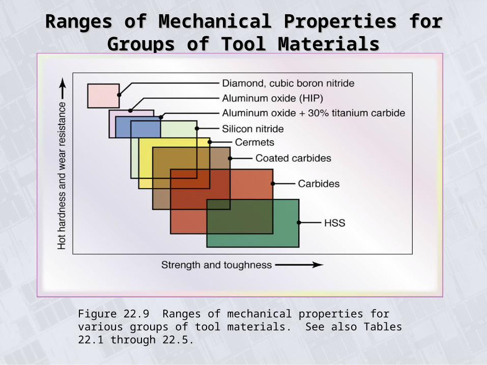
Ranges of Mechanical Properties for Groups of Ranges of Mechanical Properties for Groups of Tool MaterialsTool Materials
Figure 22.9 Ranges of mechanical properties for various groups of tool materials. See also Tables 22.1 through 22.5.
CUBIC BORON NITRIDE (CBN)CUBIC BORON NITRIDE (CBN)
• made by bonding 0.5-1-mm layer of polycrystalline CBN to a carbide substrate by sintering under pressure
• CBN tools are also made in small sizes without a substrate
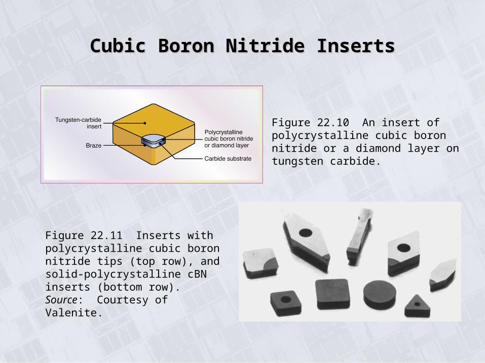
• Figure 22.10 Construction of a polycrystalline CBN or a diamond layer on a TiC insert
• Because CBN tools are brittle, stiffness of machine tool and fixturing are important in order to avoid vibration and chatter
• to avoid cracking due to thermal shock, machining should generally be performed dry, particularly in interrupted cutting operations such as milling.
• Figure 22.11 Inserts with polycrystalline CBN tips (top row) and solid polycrystalline CBN inserts (bottom row)
Cubic Boron Nitride InsertsCubic Boron Nitride Inserts
Figure 22.10 An insert of polycrystalline cubic boron nitride or a diamond layer on tungsten carbide.
Figure 22.11 Inserts with polycrystalline cubic boron nitride tips (top row), and solid-polycrystalline cBN inserts (bottom row). Source: Courtesy of Valenite.
SILICON-NITRIDE BASED CERAMICSSILICON-NITRIDE BASED CERAMICS
• Consist of SiN with various additions of Al2O3, yttrium oxide, and TiC
• Toughness, hot hardness, and good thermal-shock resistance.
• An example of a SiN-base material is sialon, composed of : Si, Al, O, and N
• It has higher thermal-shock resistance than silicon nitride
• recommended for machining cast irons and nickel-based super-alloys at intermediate cutting speeds
• Because of chemical affinity to iron, SiN-based tools are not suitable for machining steels
DIAMONDDIAMOND
• Low friction
• High wear resistance
• Ability to maintain sharp edge
• Used when good surface finish and dimensional accuracy are req. (soft non-ferrous & abrasive non-metallic materials)
• Low rack angles are generally used to provide strong cutting edge
• Used at high speed
• Most reasonable for light uninterrupted finishing cut
• Diamond is not recommended for machining plain carbon steels or titanium, because of its strong chemical affinity
Tool Costs and Reconditioning of ToolsTool Costs and Reconditioning of Tools• Tool costs vary widely, depending on the tool material, size, shape, chip-
breaker features, and quality.
• The cost for a typical 12.5-mm insert is approximately (a) $5 to $10 for uncoated carbides, (b) $6 to $10 for coated carbides, (c) $8 to $15 for ceramics, (d) $50 to $60 for diamond-coated carbides, (e) $60 to $100 for cubic boron nitride, and (f) $90 to $125 for a diamond-tipped insert.
• Tooling costs in machining have been estimated to be on the order of 2 to 4% of the manufacturing costs. This small amount is due to the fact that a single cutting tool, for example, can perform a large amount of material removal before it is indexed and eventually recycled.
• If the expected tool life can be in the range of 30 to 60 minutes. Thus, considering that a square insert has eight cutting edges, it is indicated that the tool lasts a long time before it is removed from the machine and replaced.
• Cutting tools can be reconditioned by resharpening them, using tool and cutter grinders with special fixtures. This operation may be carried out by hand or on computer-controlled tool and cutter grinders.
CUTTING FLUIDSCUTTING FLUIDS
• FunctionFunction:
1. Reduce friction & wear, improving tool life & surface finish
2. Reduce forces and energy consumption
3. Cool the cutting zone, reducing workpiece temp and thermal distortion
4. Wash away chips
5. Protect machined surface from environmental corrosion
• Situation in which cutting fluid is harmful:
1. Interrupted cutting operations
2. May cause the chip to become curlier, thus concentrating the stresses closer to the tool tip, so concentrate the heat closer to the tool tip which reduces tool life
• Depending on the type of machining operation, the cutting fluid needed may be a coolant, a lubricant, or both.
• The effectiveness of cutting fluids depends on a number of factors, such as the type of machining operation, tool and workpiece materials, cutting speed, and the method of application.
• Water is an excellent coolant and can effectively reduce the high temperatures developed in the cutting zone. However, water is not an effective lubricant; hence, it does not reduce friction. Furthermore, it can cause oxidation (rusting) of workpieces and machine-tool components.
• The need for a cutting fluid depends on the severity of the particular machining operation, which may be defined as the level of temperatures and forces encountered and the ability of the tool materials to withstand them, the tendency for built-up edge formation, the ease with which chips produced can be removed from the cutting zone.
CUTTING FLUIDSCUTTING FLUIDS
CUTTING FLUIDSCUTTING FLUIDS
• Types of cutting fluids
1. Oils (also called straight oils): typically are used for low-speed operations where temperature rise is not significant.
2. Emulsions (also called soluble oils): a mixture of oil and water and additives, generally are used for high-speed operations because the temperature rise is significant. The presence of water makes emulsions highly effective coolants. The presence of oil reduces or eliminates the tendency of water to cause oxidation.
3. Semisynthetics: are chemical emulsions containing little mineral oil, diluted in water, and with additives that reduce the size of oil particles, making them more effective
4. Synthetics: are chemicals with additives, diluted in water, and containing no oil.
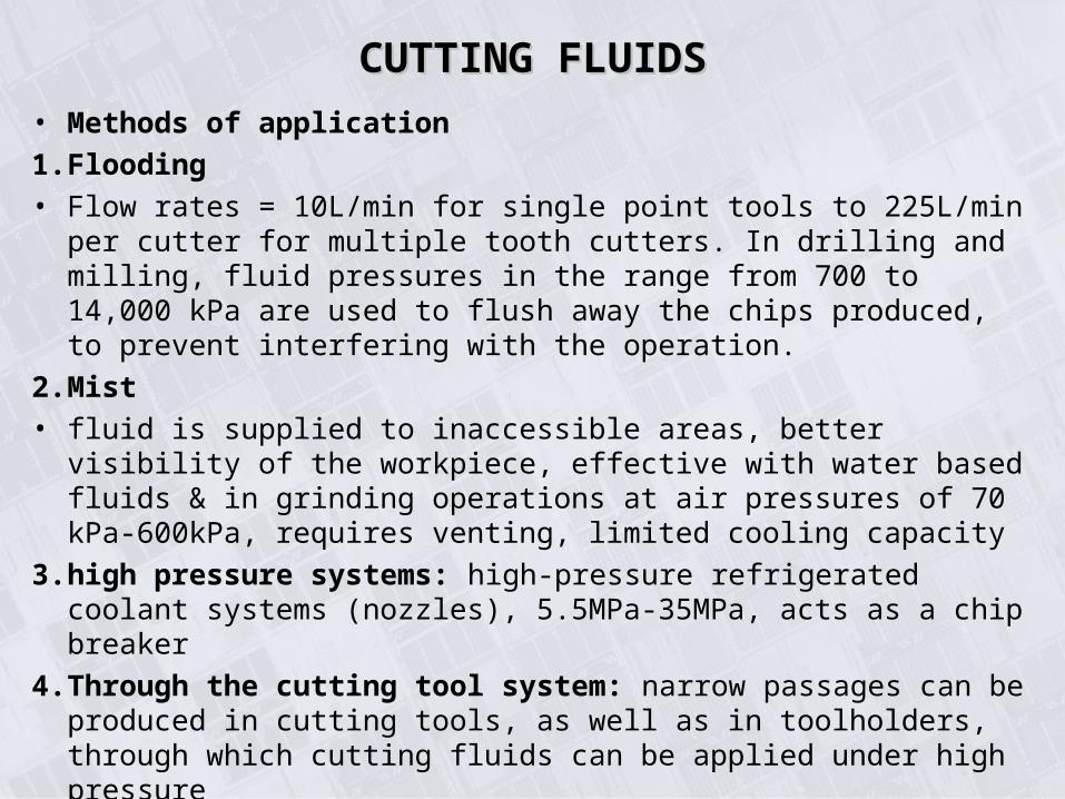
• Methods of application
1. Flooding
• Flow rates = 10L/min for single point tools to 225L/min per cutter for multiple tooth cutters. In drilling and milling, fluid pressures in the range from 700 to 14,000 kPa are used to flush away the chips produced, to prevent interfering with the operation.
2. Mist
• fluid is supplied to inaccessible areas, better visibility of the workpiece, effective with water based fluids & in grinding operations at air pressures of 70 kPa-600kPa, requires venting, limited cooling capacity
3. high pressure systems: high-pressure refrigerated coolant systems (nozzles), 5.5MPa-35MPa, acts as a chip breaker
4. Through the cutting tool system: narrow passages can be produced in cutting tools, as well as in toolholders, through which cutting fluids can be applied under high pressure
CUTTING FLUIDSCUTTING FLUIDS
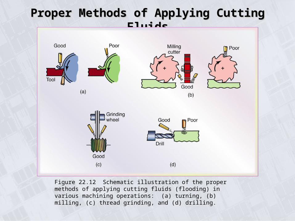
Proper Methods of Applying Cutting FluidsProper Methods of Applying Cutting Fluids
Figure 22.12 Schematic illustration of the proper methods of applying cutting fluids (flooding) in various machining operations: (a) turning, (b) milling, (c) thread grinding, and (d) drilling.

CUTTING FLUIDS-NEAR DRY AND DRY CUTTING FLUIDS-NEAR DRY AND DRY MACHININGMACHINING
• The trend has led to the practice of near-dry machining (NDM), with major benefits such as the following:
Alleviating the environmental impact of using cutting fluids, improving air quality in manufacturing plants, and reducing health hazards.
Reducing the cost of machining operations, including the cost of maintenance, recycling, and disposal of cutting fluids.
Further improving surface quality.
Related Documents