Copyright 1997 by Project Technology, Inc. - 1 - All rights reserved. Developing Shlaer-Mellor Models Using UML Stephen J. Mellor Neil Lang Project Technology, Inc. 10940 Bigge Street San Leandro, California 94577 (510) 567-0255 http://www.projtech.com This position paper describes how to represent Shlaer-Mellor Object-Oriented Analysis work products using the Unified Modeling Language. The Unified Modeling Language (UML) is a language, a notation, for expressing models of object-oriented designs. It does not prescribe a software development process, i.e., a set of techniques, guidelines and steps for constructing a set of related work products. The Shlaer-Mellor Method [SM1] is a well-defined and disciplined software construction process based on the explicit separation of the analysis of the application and the specification of the software design. In this method the system is divided into distinct, separate subject matters called domains, and each domain is analyzed using Shlaer-Mellor Object-Oriented Analysis. The method prescribes a set of well-defined analysis work products. The software design for the system as a whole is specified in a separate domain called the Software Architecture. Given a sufficiently-powerful modeling language, the Shlaer-Mellor Object-Oriented Analysis work products may be expressed in any notation. Because the UML is a powerful and flexible notation, it is possible to follow the Shlaer-Mellor process and express the Shlaer-Mellor concepts and work products using UML. This document provides a mapping from the Shlaer-Mellor work products into the UML notation, so that a project can use the Shlaer-Mellor concepts and process and yet be UML-compliant. There is no change to the process of developing Shlaer-Mellor models; the work is done in the same order and the same work products are produced. The UML notation used here is that defined in the UML Notation Guide, version 1.0 of 13 January 1997. All section references that appear in this technical note refer to the Notation Guide. We proceed by taking each of the Shlaer-Mellor work products in turn, and showing how to represent that work product using UML. Note that the UML is designed to express requirements analysis, design, and implementation concepts. Because Shlaer-Mellor OOA models capture analysis concepts exclusively, only a subset of the UML notation is required to represent the work products. Consequently each UML notational element does not always have a Shlaer-Mellor equivalent. 1. Domain Chart UML defines a package (§ 2.7) to be a grouping of elements; it is commonly used to group classes together. The UML defines a dependency (§ 4.25) between packages as a semantic relationship between

Welcome message from author
This document is posted to help you gain knowledge. Please leave a comment to let me know what you think about it! Share it to your friends and learn new things together.
Transcript
Copyright 1997 by Project Technology, Inc. - 1 -All rights reserved.
Developing Shlaer-Mellor Models
Using UML
Stephen J. MellorNeil Lang
Project Technology, Inc.10940 Bigge Street
San Leandro, California 94577(510) 567-0255
http://www.projtech.com
This position paper describes how to represent Shlaer-Mellor Object-Oriented Analysis work productsusing the Unified Modeling Language. The Unified Modeling Language (UML) is a language, a notation,for expressing models of object-oriented designs. It does not prescribe a software development process,i.e., a set of techniques, guidelines and steps for constructing a set of related work products.
The Shlaer-Mellor Method [SM1] is a well-defined and disciplined software construction process based onthe explicit separation of the analysis of the application and the specification of the software design. In thismethod the system is divided into distinct, separate subject matters called domains, and each domain isanalyzed using Shlaer-Mellor Object-Oriented Analysis. The method prescribes a set of well-definedanalysis work products. The software design for the system as a whole is specified in a separate domaincalled the Software Architecture.
Given a sufficiently-powerful modeling language, the Shlaer-Mellor Object-Oriented Analysis workproducts may be expressed in any notation. Because the UML is a powerful and flexible notation, it ispossible to follow the Shlaer-Mellor process and express the Shlaer-Mellor concepts and work productsusing UML.
This document provides a mapping from the Shlaer-Mellor work products into the UML notation, so that aproject can use the Shlaer-Mellor concepts and process and yet be UML-compliant. There is no change tothe process of developing Shlaer-Mellor models; the work is done in the same order and the same workproducts are produced.
The UML notation used here is that defined in the UML Notation Guide, version 1.0 of 13 January 1997.All section references that appear in this technical note refer to the Notation Guide.
We proceed by taking each of the Shlaer-Mellor work products in turn, and showing how to represent thatwork product using UML. Note that the UML is designed to express requirements analysis, design, andimplementation concepts. Because Shlaer-Mellor OOA models capture analysis concepts exclusively, onlya subset of the UML notation is required to represent the work products. Consequently each UMLnotational element does not always have a Shlaer-Mellor equivalent.
1. Domain Chart
UML defines a package (§ 2.7) to be a grouping of elements; it is commonly used to group classestogether. The UML defines a dependency (§ 4.25) between packages as a semantic relationship between
Copyright 1997 by Project Technology, Inc. - 2 -All rights reserved.
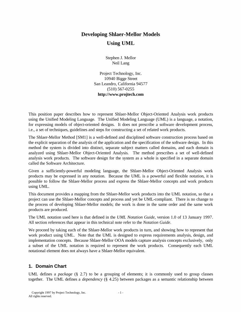
the model elements in the packages. The UML shows a package as a rectangle with a tab, and adependency as a dashed arrow pointing to the “depended on” package.
Represent each domain as a package. Place the name of the domain within the rectangle representing thepackage. Do not show the contents of any of the packages.
Represent a bridge as a dependency pointing from the client domain to the server domain. Do not label orannotate the dependency.
Figure 1.1a shows a Shlaer-Mellor notation Domain Chart, and Figure 1.1b shows the correspondingDomain Chart using UML notation.
Discussion: The UML does not have the concept of domain separation— indeed, the Notation Guide itselfmixes the definition of the language with both presentation and notation.
The UML definition of a package as a group of related model elements more closely fits the Shlaer-Mellordefinition of a subsystem. But then a domain is also a collection of closely related subsystems, so it is notunreasonable to use the UML package concept for a domain.
Similarly, the UML does not have the concept of a Shlaer-Mellor bridge in the sense of a client domainmaking use of the facilities of a server. Rather, the UML defines dependency in terms of “a change to thetarget element may require a change to the source element in the dependency.” Of course, this is preciselythe type of dependency that a Shlaer-Mellor bridge externalizes so that the link between two domains canbe changed without changing either domain.
The semantic content of a Shlaer-Mellor domain chart is quite low— it's the thinking about the subjectmatters that's important. That thinking can easily be represented using UML. But do be careful todistinguish a domain from a subsystem.
Video Kiosk
User Interface Process IO
Architecture
OperatingSystem
GUI Toolkit
Language
Figure 1.1a: Domain Chart for Kiosk System Figure 1.1b: Same Domain Chart in UML

Copyright 1997 by Project Technology, Inc. - 3 -All rights reserved.
2. Object Information Model
2.1 Objects and Attributes
A Class Diagram in UML captures the classes, their internal structure, and the relationships between them(§ 4.3). Like a Shlaer-Mellor Object Information Model (OIM), the Class Diagram defines only staticaspects and does not describe the dynamic behavior.
In UML, a class has three compartments: a name compartment (§ 4.4) at the top, a middle compartment tohold a list of attributes (§ 4.14), and a lower compartment to hold a list of operations. We use the namecompartment for the object name, number and keyletter. We place the attributes in the middlecompartment, and we leave the lower compartment empty because a Shlaer-Mellor OIM does not showprocesses assigned to objects.
Represent each object in the OIM as a UML class. Place the name in the top compartment, centered,boldfaced, and titled1 to conform to the UML style guidelines. Show the object number and keyletter (inthis order) in braces below the object name.2
Represent the attributes of an object as a list of UML attributes in the middle compartment. Add thedomain-specific data type of the attribute using the UML syntax (§ 4.14):
visibility name : type-expression = initial-value { property-string }
We examine each of these syntactic elements in turn.
The UML defines visibility to be one of public, protected or private. The UML recommends that a toolshould have the capability to suppress the visibility, though it should not be undefined. The Shlaer-Mellorprocess defers defining the visibility of an attribute until the software architecture is available. Therefore,tag each attribute as public and suppress the visibility marker. (See discussion below.)
The name is the name of the attribute.
The type-expression in UML is a language-dependent specification of the implementation type of anattribute. The language we choose for the expression of a Shlaer-Mellor work product is Shlaer-MellorOOA in which each attribute has a domain-specific data type such as temperature or pressure that we latermap to an implementation-language data type. Domain-specific data types supersede the attribute domaindefinitions described in Object-Oriented Systems Analysis: Modeling the World in Data [SM2] and aredescribed further in Appendix B. For the UML type-expression use the domain-specific data type definedfor each attribute in the OIM.
The initial-value is a default value for the attribute, which you should include if appropriate. (Thedefinition of the domain-specific data type includes the specification of a default value.)
In UML, a property string (§ 3.5) comprises a set of comma-delimited property specifications enclosed inbraces '{' and '}'. Each property specification has the form:
keyword = value
where the keyword is the name of a property and value is an arbitrary string denoting its value. If thekeyword stands alone, it denotes that the property indicated by the keyword is true. We used a propertystring for the object keyletter and number above by implicitly defining the property specification keywordsfor a given model to include all the analyst-specified object numbers and keyletters. Therefore an analystneed only set to true the keywords corresponding to a given object's number and keyletter.
1 i.e. each word begins with an upper case letter2 This construct is actually a property list, described in more detail below.
Copyright 1997 by Project Technology, Inc. - 4 -All rights reserved.
There is nothing in UML that corresponds explicitly to identifying or referential attributes. Again wemodel these concepts using property strings. Use the property specification keywords I and Rn (therelationship number) to indicate identifying and referential attributes. Always use the short form { I } or {Rn } in which the Boolean value is taken to be true rather than the longer form { I = true }. Use thekeywords I2, I3 for secondary and tertiary identifiers if desired. Similarly use the property specificationkeyword M to indicate a computed or mathematically-dependent attribute.
The following table lists some kinds of attributes and their combinations:
Kind of Attribute Shlaer-MellorNotation Example
Property String inUML
Primary Identifying Attribute * { I }
Secondary Identifying Attribute *2 { I2 }
Attribute in multiple identifiers *1, *2 { I, I2 }
Referential attribute R3 { R3 }
Referential identifying attribute * ......... (R4) { I, R4 }
Mathematically dependent attribute (M) { M }
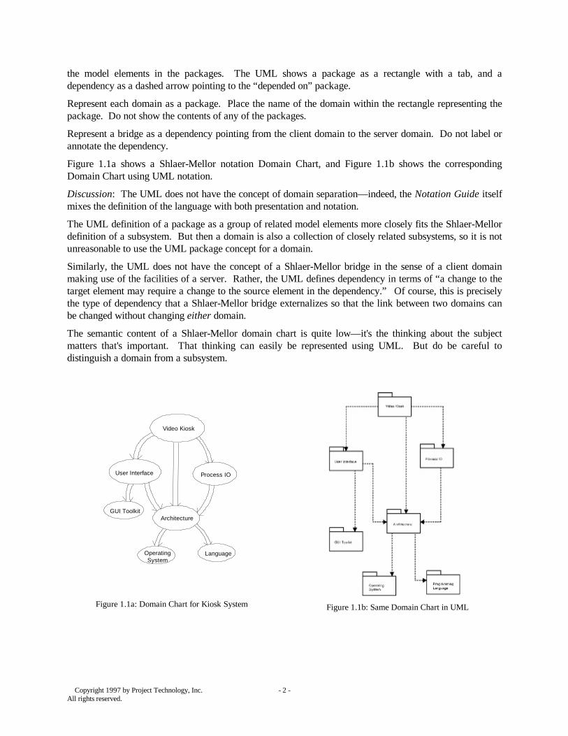
The OIM in figures 2.1a and 2.1b show objects in Shlaer-Mellor and UML notation respectively.
Discussion. Shlaer-Mellor defers defining the visibility of an attribute in the model of a domain. Thedeveloper tags each attribute to be one of the options defined to be available in the software architectureduring the definition of the bridges. Within a single domain then, Shlaer-Mellor does not require that theanalyst specify visibility. On the other hand, the UML requires its definition but allows suppression of thevisibility marker. Consequently, it makes no difference which visibility marker you select.
Because the purpose of analysis is to expose information, we recommend defining the visibility to bepublic. Alternatively, if you wish to avoid the mistaken impression that the presence of an attribute on aOIM necessarily implies violation of encapsulation, you could define the visibility to be private.
2.2 Binary Relationships
A binary association (§ 4.17) in UML captures a combination of analysis and design concepts. A binaryassociation is shown as a solid path connecting the class symbols, named with a single verb phrase. Avariety of adornments may be shown at each end of the line.
Represent a Shlaer-Mellor binary relationship as a UML binary association. Name the relationship withthe concatenation of the relationship number and a single verb phrase, and place this combination near themiddle of the association line. Choose the single verb phrase from one of the two verb phrases normallyused to name the relationship and use a solid triangle at the left or right end of the verb phrase to indicatethe direction in which to read the name. For verb phrases located next to a vertically-drawn associationline use a solid triangle pointing to the right to indicate a direction of top to bottom.
UML reserves each end of the association line for the association role (§ 4.18), with the adornments:
• multiplicity (§ 4.19),• aggregation indicator,• qualifier, (§ 4.20),• role name,

Copyright 1997 by Project Technology, Inc. - 5 -All rights reserved.
• ordering,• navigability.
We discuss each in turn.
In UML, multiplicity is a combination of multiplicity and conditionality in Shlaer-Mellor. It is an analysisconcept. Use the following correspondences:
Shlaer-Mellor Concept SM Symbol UML SymbolOne Unconditional (x:1) — > 1One Conditional (x:1c) — >c 0..1Many Unconditional (x:M) — >> 1..*Many Conditional (x:Mc) — >>c 0..*
Do not use arrowheads since they represent how to link the classes in design (navigability).
In UML, the aggregation indicator is used to indicate aggregation or composition. If the diamond at oneend of an association path is hollow, then the implication is that it is an aggregation. If the diamond isfilled, then it's composition (§ 4.23). Shlaer-Mellor thinks of aggregation as a design concept and hencethere is no corresponding concept in the OIM to map to either type of aggregation.
In UML, the qualifier is an attribute or set of attributes whose values partition the set of related objectsacross an association. Since the referential attributes formalizing a relationship in a Shlaer-Mellor OIMserve the same purpose, do not add a qualifier to the model.
In UML, the role name that can appear at each end of an association path reflects the role of the class inthe association. Hence in a relationship Dog Owner OWNS/IS OWNED by Dog, the role name for the Dogobject would be IS OWNED BY. Or, because UML names roles using nouns, more likely it would beOWNER. Unfortunately, this is quite the opposite of the Shlaer-Mellor convention where we associate theverb phrase with the object of the sentence, and the verb phrase associated with Dog would be OWNS.
In the Shlaer-Mellor Method, roles are typically captured in the name of the participating objects and thereis no need for this adornment. Consequently, we recommend that you not use the role names, despite theirconvenient location.
Both ordering and navigability are design-relevant constructs and hence are not required in the analysismodels.
The OIM in figures 2.1a and 2.1b show relationships in Shlaer-Mellor and UML notation respectively.
2.3 Associative Objects
An association class (§ 4.21) in UML is an association that also has class properties. UML shows anassociation class as a class connected by a dashed line to an association path. The UML conceptcorresponds closely to the Shlaer-Mellor concept of an associative object.
Represent an associative object with an association class connected to the corresponding association. Treatthe associative object like any other object in listing the attributes, etc. To indicate a M-M:M relationship,add M to the property string in the name compartment.
The OIM in figures 2.1a and 2.1b show an associative object and the corresponding association class.
Discussion: UML treats the association and its corresponding class as a single model element with a singlename. In a Shlaer-Mellor OOA model the name of the associative object is always a noun and
Copyright 1997 by Project Technology, Inc. - 6 -All rights reserved.
Figure 2.1a: Object Information Model for Kiosk System
Figure 2.1b: Object Information Model in UML
Copyright 1997 by Project Technology, Inc. - 7 -All rights reserved.
the name of the relationship it formalizes is always a pair of verb phrases. To be consistent with UML weshould formally treat the single name of the class and the association as the concatenation of the Shlaer-Mellor OOA object name and one of the verb phrases. Then show in the association class only the objectpart of the full name and on the association line only the verb phrase part.
2.4 Subtype/Supertype Relationships
Generalization (§ 4.24) in UML is a relationship between a more general element and a more specificelement that adds additional detail. UML shows generalization as a solid line from the more specificelement to the more general element with a large hollow triangle at the more general element end. We applythe generalization construct to classes to model Shlaer-Mellor subtypes/supertypes.
Represent a subtype/supertype construct with a generalization line directed from each subtype to thesupertype. For maximum overlap with current notation, always show a generalization structure as a treewith a shared segment pointing to the class for the supertype object and branches to each of the classes forthe subtype objects. Add a property string with the relationship number next to the shared segment of thegeneralization structure. Do not add a “discriminator: powertype” label to the model.
UML provides a set of predefined constraints to indicate some semantic constraints among the classes. TheUML semantics in the absence of explicit constraints are incomplete (there may be further subtypes beyondthose specified) and disjoint (an instance of a supertype belongs to one and only one subtype). Torepresent the full Shlaer-Mellor semantics of partitioning into mutually exclusive subsets, annotate theshared segment with {complete, disjoint}.
Discussion: The semantics of a Shlaer-Mellor subtype/supertype relationship are tightly specified.Instances of the supertype object are partitioned completely and mutually-exclusively into instances of thesubtypes. In contrast, UML classes and subclasses are related much more loosely. For instance it is notrequired to define or show all subclasses derived from a class. Since the constraint set {complete, disjoint}corresponding to the Shlaer-Mellor semantics differs from the default, we show the constraints on themodel. Alternatively one could omit disjoint and simply show a {complete} constraint.
3. State Models
UML models behavior using a variation of Harel's Statecharts [H1]. In UML, actions can be specified fortransitions, upon entry into states, upon exit from states, and even within states. UML also offers acontinuously executing activity within a state that can be interrupted upon receipt of an event. In addition,UML allows for a superstate with states embedded within it.
The Shlaer-Mellor Method prescribes a much more concise state modeling formalism [SM2] derived fromMoore [M1] with flat, deterministic state models where (uninterruptable) actions are executed upon entryinto states. In the Shlaer-Mellor Method we describe complex behavior by abstracting additional states andobjects, each of which is at the same granularity.
In UML, a state (§ 8.2) is shown as a rounded rectangle with up to three compartments— one each for aname, state variables, and internal activity.
Represent a Shlaer-Mellor state in UML as a UML state with only a name and internal activitycompartment. Place the name of the state in the name compartment, combined with the state number, ifdesired. In the activity compartment, write “entry /” to signify that the action is to be executed on entry tothe state. Do not create “do” or “exit” actions. Enter the action either as an informal action description oras formal action language, just as it normally appears in a Shlaer-Mellor state model (UML does notspecify a syntax for action descriptions.).
Copyright 1997 by Project Technology, Inc. - 8 -All rights reserved.
UML defines events very broadly: conditions, signals, invocations and the expiration of some passage oftime all qualify as events. Shlaer-Mellor uses only signal events. In UML, a signal event (§ 8.4) is definedby:
event-name '(' comma-separated-parameter-list ')'
where each parameter in the comma-separated-parameter-list is:
parameter-name ':' type-expression
Concatenate the event label and event meaning to form the UML-event name. Use the name and domain-specific data type of each Shlaer-Mellor event data item to create each parameter. Do not use a semicolonto separate the identifying attributes from the supplemental data. For example:
Shlaer-Mellor Notation UML Notation
K1:Request Video Clip (Kiosk Number;Video Clip Title)
K1_Request_Video_Clip (Kiosk Number :symbolic, Video Clip Title : symbolic)
UML shows a transition (§ 8.5) as a solid arrow pointing from the starting state to the ending state. Eachtransition carries a transition string that has the following general format:
event-signature '['guard-condition ']' '/' action '^' send clause
where the event-signature describes an event with its actual arguments.
Because Shlaer-Mellor labels a transition only with the event name and a list of parameters, do not specifyany guard conditions, actions, or send clauses. Use only the event-signature part of the transition string toannotate the transition.
Represent a transition into a creation state as a transition from a UML-initial state to the actual creationstate. Label the transition with the creation event (A UML-initial state is a pseudo state shown as a solidfilled circle.).
Represent a final state in UML just in the same way as the Shlaer-Mellor notation: a state with notransitions out of the state. UML includes the concept of a final (pseudo) state but it is associated with atransition from a state to the enclosing superstate. Hence this type of final state is not used in representingShlaer-Mellor models.
Although UML permits labeling a transition with a time expression to indicate a transition occurs at that(absolute) time or after a specified time interval, continue to use the Shlaer-Mellor delayed event formalismto represent such time-related events.
There is no direct analog in UML for the State Transition Table. Nevertheless continue to build a STT(either manually or using table features supported by your tool) for each active object to specify itsbehavior completely.
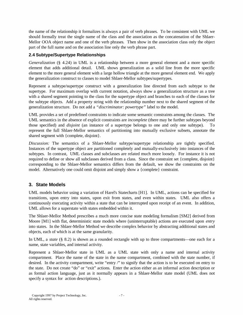
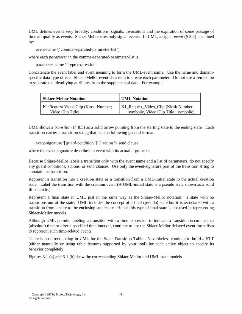
Figures 3.1 (a) and 3.1 (b) show the corresponding Shlaer-Mellor and UML state models.
Copyright 1997 by Project Technology, Inc. - 9 -All rights reserved.
Figure 3.1a: State Model for Digital Video Disk
Figure 3.1b: State Model in UML

Copyright 1997 by Project Technology, Inc. - 10 -All rights reserved.
4. Object Communication Model
UML defines a variety of diagrams to show communication at the (UML) object level. We use one of thesediagrams— the collaboration diagram— to represent the Object Communication Model.
In UML, a collaboration diagram (§ 7.5) is a network of (UML) objects and links between them. UMLshows each object on the collaboration diagram as a rectangle with an upper name compartment and alower attribute compartment. The top compartment shows the name of the object followed by its class allunderlined to indicate the object-level nature. The lower compartment shows the attributes of the objectand their values.
A link (§ 7.9) is an instance of an association between objects and is shown as a path between them. Eachlink is annotated with a message flow (§ 7.10)— an arrow labeled with a message label— to indicate thesending of a message from one object to the other. The link is used to transport the message to the targetobject. A message may be implemented in many different ways: direct procedure calls, sending of signals,the direct raising of an event, etc. UML specifies various kinds of arrowheads to denote different kinds ofmessages, but since these are implementation decisions they have no place in an analysis model.
To produce an OCM represent each OOA object as a UML object. In the top compartment place the nameof the OOA object preceded by a semicolon. Underline the object name to follow the UML objectconvention. (See discussion below) Do not add the attribute compartment.
Represent an event generated in one OOA object to another as a link connecting the two rectangles. Do notplace an arrowhead at the destination end of the link.
Place a message flow, i.e., a labeled arrow next to each of the links. To indicate the direction of themessage flow use a half-stick arrowhead (the UML notation to indicate asynchronous flow of control).
UML allows for the specification of multiple items (sequence numbers, predecessor sequences, returnvalues) in a message label in addition to the message name itself. Simply label the message with the nameof the generated event. Do not include the event data.
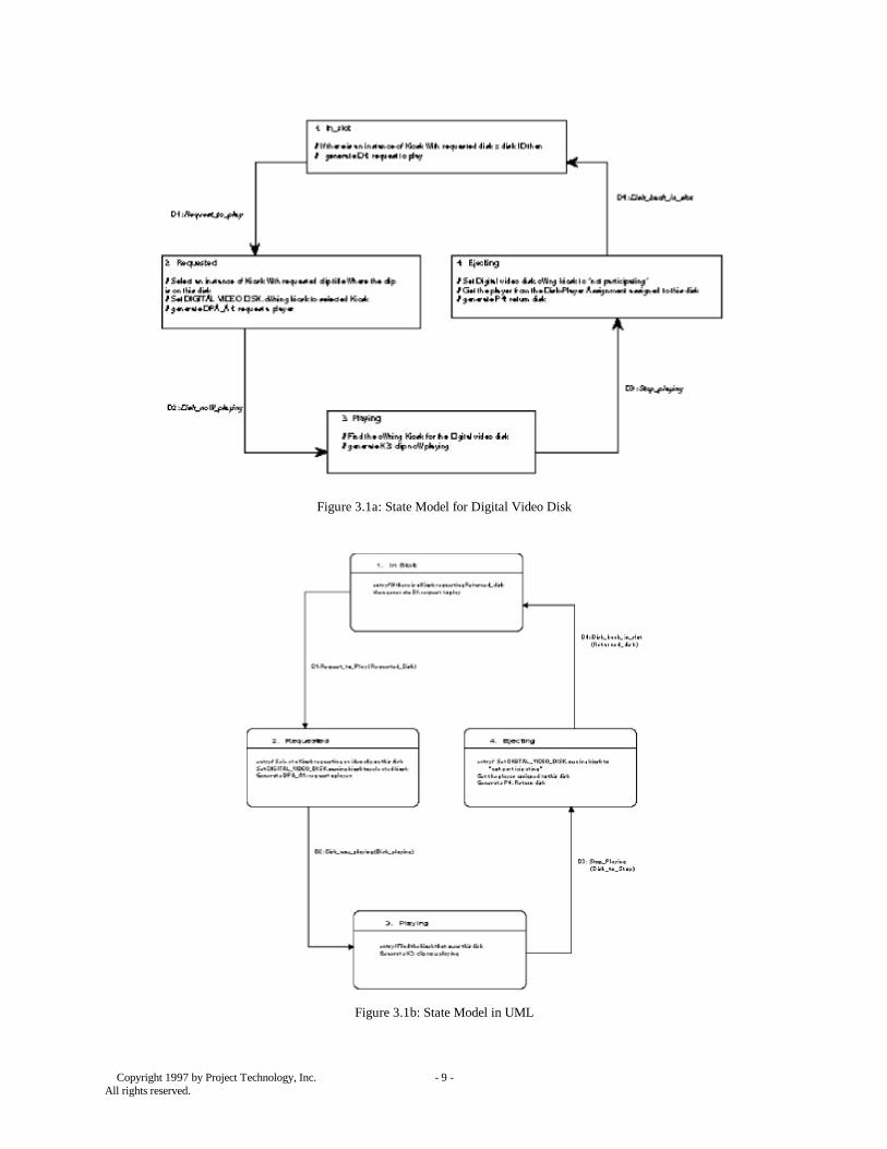
Figures 4.1a and 4.1b show the corresponding Shlaer-Mellor and UML Object Communication Models.
Discussion: Note that the definition of an object in Shlaer-Mellor refers to a typical, but unspecifiedinstance of some abstraction, whereas an object in UML is a specific instance of a class. Consequently, aShlaer-Mellor Object Communication Model shows communication between typical instances, while aUML collaboration diagram shows communication between specific instances of classes.
UML distinguishes an object from a class by separating the name of an instance of the class from the classname by a colon. UML also uses underlining to indicate the object nature of a diagram. Hence, UMLrepresents the (Shlaer-Mellor) instance of Kiosk named Amtrak Station as Amtrak Station : Kiosk. UMLpermits the use the shortened form : <class name> (a colon, followed by the class name, all underlined) torefer to an unspecified instance, hence : Kiosk refers to an unspecified instance of Kiosk. This is the formthat we use in building an OCM.
Copyright 1997 by Project Technology, Inc. - 11 -All rights reserved.
Figure 4.1a: Object Communication Model for Kiosk System Figure 4.1b: Object Communication Model in UML
5. Thread of Control Chart
UML defines another diagram— the sequence diagram— to show a pattern of interaction among the (UML)objects arranged in time sequence. In UML, a sequence diagram (§ 6.1) shows the objects participating inan interaction as they evolve over time and the message communication between them. One axis (usuallythe vertical one) represents time. The objects are placed along the other axis. A vertical dashed linerepresents the object lifeline (§ 6.2) of each object. A lifeline captures the activations (§ 6.3) of its objects,i.e., periods of time in which the object is executing some activity. Activations are denoted by a thinrectangle along the lifeline; the top and bottom of the rectangle indicate the initiation and completion timerespectively of the activation.
Messages (§ 6.4) represent communications between objects and are shown as horizontal solid arrowspointing from the sender object's lifeline to that of the destination object. The arrow is labeled with thename of the message and its arguments and optionally sequence numbers and guard conditions. UML alsopermits variations on the type of arrows to further specify the nature of the message passing mechanism(e.g., procedure calls versus asynchronous messages).
Because of the great similarity between the thread of control chart and the sequence diagram, we use thesequence diagram to represent the Thread of Control Chart. Each instance in a Shlaer-Mellor thread ofcontrol is represented by an object on the sequence diagram and each event appears as a message.
Copyright 1997 by Project Technology, Inc. - 12 -All rights reserved.
Represent each instance in the thread with a UML object placed at either the top of the sequence chart orwhere that instance comes into existence (if it is created during the evolution of the thread). Label theinstances as follows:
value-of-primary-identifier : object-name
Underline the labels to indicate the UML object nature of these entities in the diagram. If an instance isdeleted during the thread, show that on the diagram by terminating its lifeline with a large X.
Show each event in the thread of control chart as a UML message by drawing a solid horizontal arrowfrom the generator of the event to the receiving instance at the appropriate time. Self-directed events areshown as arrows that loop back to the originator's lifeline. Label each message with name of the event and(optionally) the values of the event data passed.
Represent the action executed by an instance (upon completion of a transition) as a short activation, i.e., athin rectangle along the lifeline. Label the activation using a UML note with the name of the state. Showany events generated during the action as messages originating during the activation.
Discussion: Shlaer-Mellor Thread of Control Charts often capture a large number of instances, states, andevents. In many cases it is practical to only number the states and to label the events with only the eventlabel omitting the full event name and actual values of the event data. Accordingly, when drawing thesequence diagram, label the activations only with the number of the state, and label the messages with onlythe event label when space is a consideration.
Note that UML allows for a variety of arrowheads on messages to distinguish among asynchronous andvarious synchronous messages. The Shlaer-Mellor process again defers this implementation decision to thearchitecture. Consequently use a filled arrowhead and do not attempt to further elaborate the messagepassing mechanism.
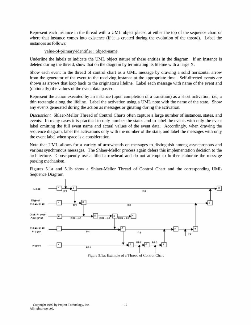
Figures 5.1a and 5.1b show a Shlaer-Mellor Thread of Control Chart and the corresponding UMLSequence Diagram.
Figure 5.1a: Example of a Thread of Control Chart
Copyright 1997 by Project Technology, Inc. - 13 -All rights reserved.
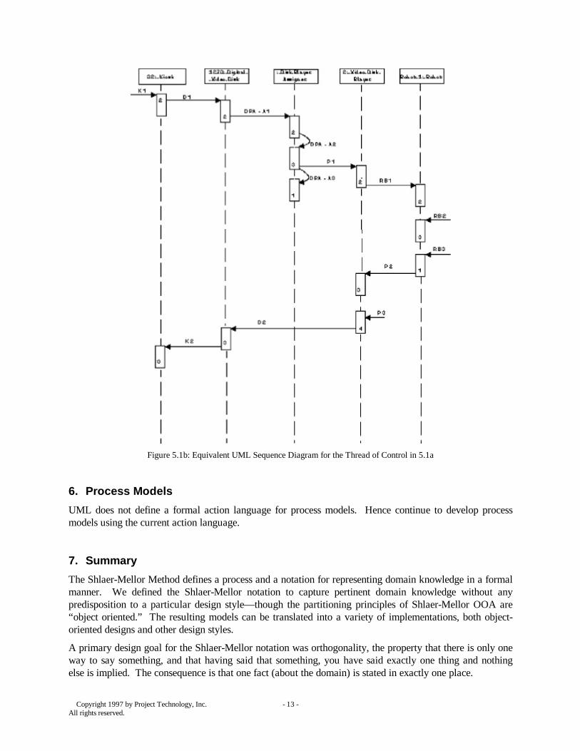
Figure 5.1b: Equivalent UML Sequence Diagram for the Thread of Control in 5.1a
6. Process Models
UML does not define a formal action language for process models. Hence continue to develop processmodels using the current action language.
7. Summary
The Shlaer-Mellor Method defines a process and a notation for representing domain knowledge in a formalmanner. We defined the Shlaer-Mellor notation to capture pertinent domain knowledge without anypredisposition to a particular design style— though the partitioning principles of Shlaer-Mellor OOA are“object oriented.” The resulting models can be translated into a variety of implementations, both object-oriented designs and other design styles.
A primary design goal for the Shlaer-Mellor notation was orthogonality, the property that there is only oneway to say something, and that having said that something, you have said exactly one thing and nothingelse is implied. The consequence is that one fact (about the domain) is stated in exactly one place.
Copyright 1997 by Project Technology, Inc. - 14 -All rights reserved.
The UML, on the other hand, is a notation for object-oriented designs where the design goal was a richnessof expression capable of encompassing all (object-oriented) development phases. The notation is richenough to capture the Shlaer-Mellor semantics, so it is possible to represent Shlaer-Mellor models using asubset of UML.
The UML does not define a process, though there are plans to add one. Shlaer-Mellor defines atranslation-based process. As a consequence, a project can use the Shlaer-Mellor process and gain theadvantages of implementation by translation, while at the same time being UML compliant.
Copyright 1997 by Project Technology, Inc. - 15 -All rights reserved.
Appendix A: Shlaer-Mellor to UML Reference List
The major diagrammatic work products of a Shlaer-Mellor Object-Oriented Analysis model can berepresented unambiguously using UML notation. The following table shows the UML diagrams used torepresent various Shlaer-Mellor models.
Shlaer-Mellor Work Product UML diagram
Domain Chart Package Diagram
Object Information Model Class Diagram
State Transition Diagram State Diagram
Object Communication Model Collaboration Diagram
Thread of Control Chart Sequence Diagram
Appendix B: Domain-Specific Data Typing in Shlaer-Mellor OOA
Domain-specific data types are defined by providing a name, an appropriate base data type, and certainparticular characteristics that are required by the selected base data type, as described below.
An enumerated data type is a data type that permits a finite set of values. Define the values, and(optionally) a default.
Use a symbolic data type for data elements that have the nature of names. Specify the minimum andmaximum number of characters and (optionally) a default.
If a data type is numeric in nature, use a numeric base data type. Specify a range, with a low and highlimit, and the precision. Specify the units, such as centimeters or degrees Celsius and a (optional) default.
In contrast to a numeric data type, an ordinal data type can be used only to express a complete or partialordering.
Use a time or duration base type to specify calendar-clock time. Specify a range and a precision.
To define a data type for data elements that represent arbitrary identifiers, use the base type arbitrary.
Bibliography
H1: David Harel, State Charts: A Visual Formalism for Complex Systems, Science of ComputerProgramming Vol 8 1987.
M1: E. F. Moore, Gedanken-Experiments on Sequential Machines, Automata Studies, PrincetonUniversity Press, Princeton, New Jersey, 1956.
SM1: Sally Shlaer and Stephen J. Mellor, The Shlaer-Mellor Method, Technical Paper, ProjectTechnology, Inc., 1996, http://www.projtech.com/smmethod/smmethod.html
SM2: Sally Shlaer and Stephen J. Mellor, Object-Oriented Systems Analysis: Modeling the World inData, Prentice Hall, 1988.
SM3: Sally Shlaer and Stephen J. Mellor, Object Lifecycles: Modeling the World in States, PrenticeHall, 1992.
Related Documents


![cartaz - aritmar.gal · aRi[t]mar galiza e portugal premio ao mellor tema musical galego premio ao mellor tema musical portugués Premio ao mellor poema portugués premio ao mellor](https://static.cupdf.com/doc/110x72/5f6b198371734345df77d704/cartaz-aritmar-galiza-e-portugal-premio-ao-mellor-tema-musical-galego-premio.jpg)