Detcon Model Series DM-600IS Explosion Proof and Intrinsically Safe Toxic Gas Sensors Operator’s Installation and Instruction Manual DETCON, Inc. 4055 Technology Forest Blvd. Suite 100, The Woodlands, Texas 77381 Ph.281.367.4100 / Fax 281.298.2868 www.detcon.com August 17, 2015 • Document #2448 • Revision 1.6.1

Welcome message from author
This document is posted to help you gain knowledge. Please leave a comment to let me know what you think about it! Share it to your friends and learn new things together.
Transcript
Detcon Model Series
DM-600ISExplosion Proof and Intrinsically Safe Toxic Gas Sensors
Operator’s Installation and Instruction Manual
4055 TechThe
Ph.281.3
August 17, 2
DETCON, Inc.nology Forest Blvd. Suite 100,Woodlands, Texas 7738167.4100 / Fax 281.298.2868
www.detcon.com015 • Document #2448 • Revision 1.6.1

DM-600IS
DM-600IS Instruction Manual ii
This page left intentionally blank
DM-600IS
DM-600IS Instruction Manual iii
Table of Contents
1.0 Description................................................................................................................................................ 2
1.1 Sensor Technology............................................................................................................................... 21.2 Universal Microprocessor Control Transmitter Circuit........................................................................ 31.3 Base Connector Board.......................................................................................................................... 31.4 Explosion Proof Enclosure................................................................................................................... 4
2.0 Principle of Operation............................................................................................................................. 5
3.0 Application ............................................................................................................................................... 5
3.1 Sensor Placement/Mounting................................................................................................................. 53.2 Interference Data .................................................................................................................................. 53.3 Interference Gas List ............................................................................................................................ 63.4 Interference Gas Table (page 1 of 5).................................................................................................... 7
4.0 Specifications.......................................................................................................................................... 12
5.0 Installation.............................................................................................................................................. 13
5.1 Field Wiring Table (4-20 mA output) ................................................................................................ 135.2 Sensor Location.................................................................................................................................. 145.3 Local Electrical Codes........................................................................................................................ 155.4 Installation Procedure......................................................................................................................... 165.5 Remote Mounting Applications ......................................................................................................... 20
6.0 Startup .................................................................................................................................................... 21
6.1 Initial Operational Tests ..................................................................................................................... 21
7.0 Operating Software & Magnetic Interface.......................................................................................... 22
7.1 Normal Operation............................................................................................................................... 227.2 Calibration Mode................................................................................................................................ 22
7.2.1 Zero Adjustment ......................................................................................................................... 227.2.2 Span Adjustment ......................................................................................................................... 22
7.3 Program Mode.................................................................................................................................... 227.3.1 Program Status........................................................................................................................... 227.3.2 Alarm 1 Level Adjustment .......................................................................................................... 237.3.3 Alarm 2 Level Adjustment .......................................................................................................... 237.3.4 Calibration Level Adjustment..................................................................................................... 23
7.4 Programming Magnet Operating Instructions .................................................................................... 23
8.0 Software Flow Chart ............................................................................................................................. 25
9.0 Calibration.............................................................................................................................................. 26
9.1 Calibration Procedure – Zero ............................................................................................................. 269.2 Calibration Procedure – Span............................................................................................................. 269.3 Additional Notes................................................................................................................................. 279.4 Calibration Frequency ........................................................................................................................ 28
10.0 Status of Programming, Version, Alarms, Calibration Level, RS-485, and Sensor Life ................ 28
11.0 Programming Alarms............................................................................................................................ 29
11.1 Alarm Levels ...................................................................................................................................... 2911.2 Alarm Reset........................................................................................................................................ 2911.3 Other Alarm Functions....................................................................................................................... 29
12.0 Program Features .................................................................................................................................. 30
DM-600IS
DM-600IS Instruction Manual iv
13.0 Universal Transmitter Feature (Re-Initialization) ............................................................................. 31
14.0 RS-485 Protocol..................................................................................................................................... 32
15.0 Display Contrast Adjust........................................................................................................................ 34
16.0 Trouble Shooting.................................................................................................................................... 34
17.0 Spare Parts List...................................................................................................................................... 36
18.0 Warranty ................................................................................................................................................ 38
19.0 Service Policy.......................................................................................................................................... 38
20.0 Revision History..................................................................................................................................... 38
Table of FiguresFigure 1 Construction of Electrochemical Sensor............................................................................................. 3Figure 2 Universal Microprocessor Control Transmitter circuit ....................................................................... 3Figure 3 Base connector board.......................................................................................................................... 4Figure 4 Explosion-Proof Enclosure ................................................................................................................. 4Figure 5 Functional Block Diagrram................................................................................................................. 5Figure 6 Typical Installation ............................................................................................................................. 15Figure 7 Typical Outline and Mounting Dimensions........................................................................................ 16Figure 8 Sensor wiring ...................................................................................................................................... 17Figure 9 Alarm Programming Jumpers ............................................................................................................. 17Figure 10 RS-485 ID set Dip Switch................................................................................................................. 18Figure 11 Remote wiring diagram..................................................................................................................... 20Figure 12 Programming magnet........................................................................................................................ 23Figure 13 Programming Switch locations ......................................................................................................... 24Figure 14 Software Flow Chart ......................................................................................................................... 25Figure 15 Spare parts diagram........................................................................................................................... 36
List of TablesTable 1 Model #, Gas Name and Symbol.......................................................................................................... 1Table 2 Sensor cell specifications ..................................................................................................................... 12Table 3 Field wiring Table ................................................................................................................................ 13Table 4 Over-current Protection per AWG ....................................................................................................... 13Table 5 RS-485 Rotary Dip Switch Settings...................................................................................................... 19Table 6 IS Sensor Head / Plug-in Replacement Sensor Cell ............................................................................. 37
Shipping Address 4055 Technology Forest Blvd. Suite 100. The Woodlands Texas 77381Mailing Address: P.O. Box 8067, The Woodlands Texas 77387-8067
Phone: 888.367.4286, 281.367.4100 • Fax: 281.292.2860 • www.detcon.com • [email protected]
DM-600IS
DM-600IS Instruction Manual Rev 1.6.1 Page 1 of 38
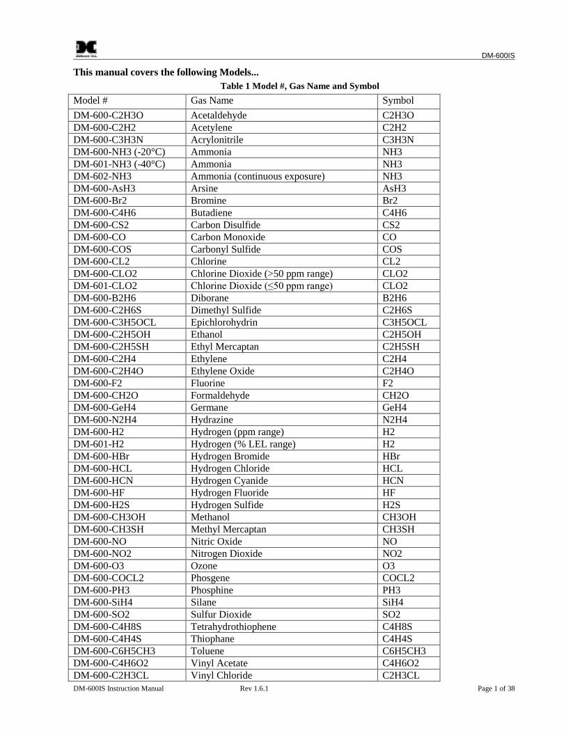
This manual covers the following Models...
Table 1 Model #, Gas Name and Symbol
Model # Gas Name Symbol
DM-600-C2H3O Acetaldehyde C2H3ODM-600-C2H2 Acetylene C2H2DM-600-C3H3N Acrylonitrile C3H3NDM-600-NH3 (-20°C) Ammonia NH3DM-601-NH3 (-40°C) Ammonia NH3DM-602-NH3 Ammonia (continuous exposure) NH3DM-600-AsH3 Arsine AsH3DM-600-Br2 Bromine Br2DM-600-C4H6 Butadiene C4H6DM-600-CS2 Carbon Disulfide CS2DM-600-CO Carbon Monoxide CODM-600-COS Carbonyl Sulfide COSDM-600-CL2 Chlorine CL2DM-600-CLO2 Chlorine Dioxide (>50 ppm range) CLO2DM-601-CLO2 Chlorine Dioxide (≤50 ppm range) CLO2DM-600-B2H6 Diborane B2H6DM-600-C2H6S Dimethyl Sulfide C2H6SDM-600-C3H5OCL Epichlorohydrin C3H5OCLDM-600-C2H5OH Ethanol C2H5OHDM-600-C2H5SH Ethyl Mercaptan C2H5SHDM-600-C2H4 Ethylene C2H4DM-600-C2H4O Ethylene Oxide C2H4ODM-600-F2 Fluorine F2DM-600-CH2O Formaldehyde CH2ODM-600-GeH4 Germane GeH4DM-600-N2H4 Hydrazine N2H4DM-600-H2 Hydrogen (ppm range) H2DM-601-H2 Hydrogen (% LEL range) H2DM-600-HBr Hydrogen Bromide HBrDM-600-HCL Hydrogen Chloride HCLDM-600-HCN Hydrogen Cyanide HCNDM-600-HF Hydrogen Fluoride HFDM-600-H2S Hydrogen Sulfide H2SDM-600-CH3OH Methanol CH3OHDM-600-CH3SH Methyl Mercaptan CH3SHDM-600-NO Nitric Oxide NODM-600-NO2 Nitrogen Dioxide NO2DM-600-O3 Ozone O3DM-600-COCL2 Phosgene COCL2DM-600-PH3 Phosphine PH3DM-600-SiH4 Silane SiH4DM-600-SO2 Sulfur Dioxide SO2DM-600-C4H8S Tetrahydrothiophene C4H8SDM-600-C4H4S Thiophane C4H4SDM-600-C6H5CH3 Toluene C6H5CH3DM-600-C4H6O2 Vinyl Acetate C4H6O2DM-600-C2H3CL Vinyl Chloride C2H3CL
DM-600IS
DM-600IS Instruction Manual Rev 1.6.1 Page 2 of 38
1.0 Description
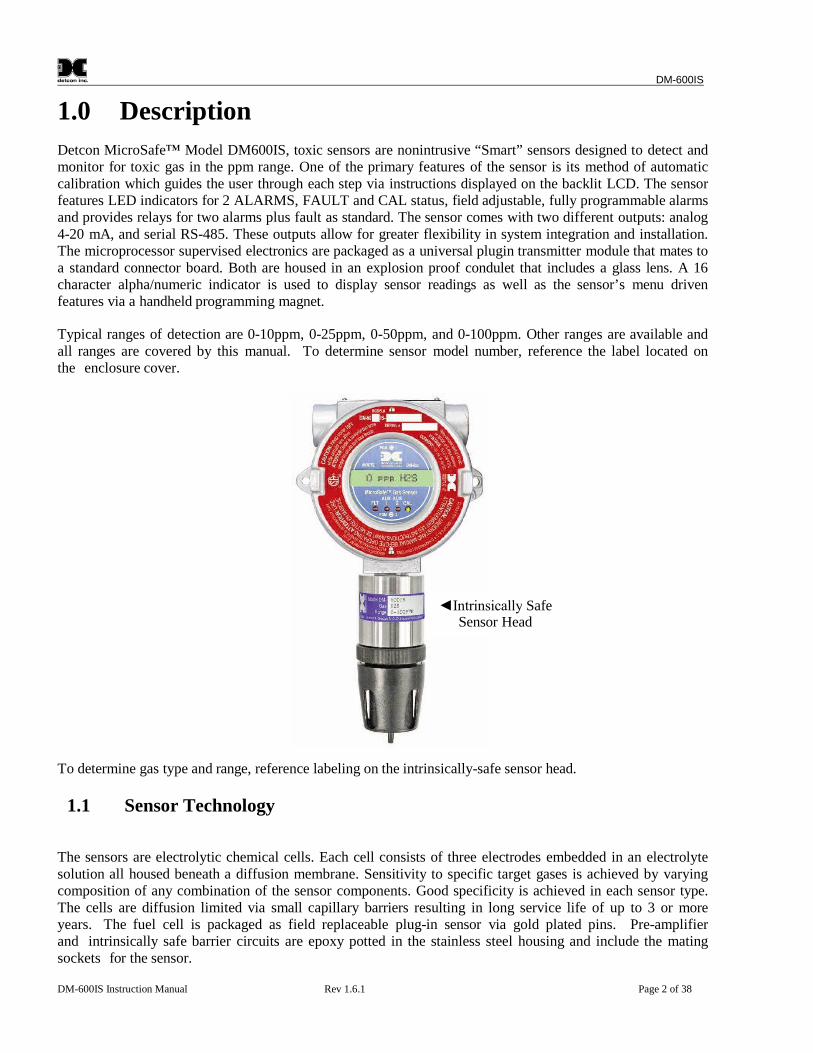
Detcon MicroSafe™ Model DM600IS, toxic sensors are nonintrusive “Smart” sensors designed to detect andmonitor for toxic gas in the ppm range. One of the primary features of the sensor is its method of automaticcalibration which guides the user through each step via instructions displayed on the backlit LCD. The sensorfeatures LED indicators for 2 ALARMS, FAULT and CAL status, field adjustable, fully programmable alarmsand provides relays for two alarms plus fault as standard. The sensor comes with two different outputs: analog4-20 mA, and serial RS-485. These outputs allow for greater flexibility in system integration and installation.The microprocessor supervised electronics are packaged as a universal plugin transmitter module that mates toa standard connector board. Both are housed in an explosion proof condulet that includes a glass lens. A 16character alpha/numeric indicator is used to display sensor readings as well as the sensor’s menu drivenfeatures via a handheld programming magnet.
Typical ranges of detection are 0-10ppm, 0-25ppm, 0-50ppm, and 0-100ppm. Other ranges are available andall ranges are covered by this manual. To determine sensor model number, reference the label located onthe enclosure cover.
To determine gas type and range, reference labeling on the intrinsically-safe sensor head.
1.1 Sensor Technology
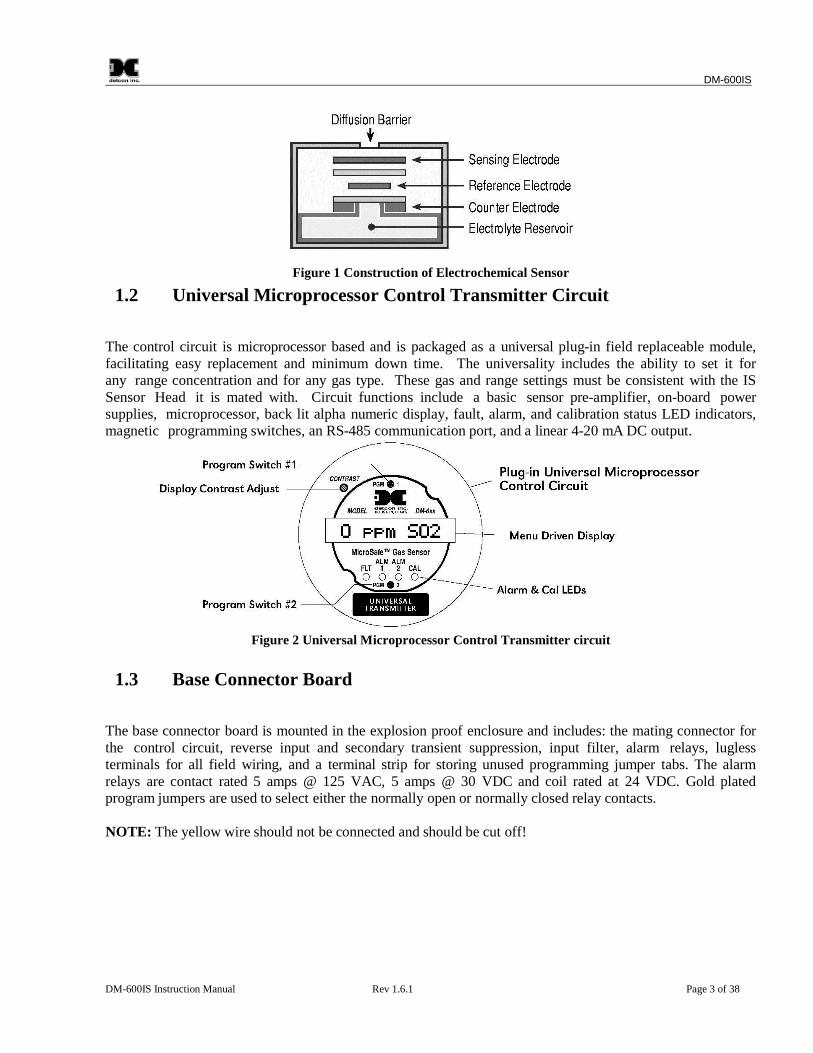
The sensors are electrolytic chemical cells. Each cell consists of three electrodes embedded in an electrolytesolution all housed beneath a diffusion membrane. Sensitivity to specific target gases is achieved by varyingcomposition of any combination of the sensor components. Good specificity is achieved in each sensor type.The cells are diffusion limited via small capillary barriers resulting in long service life of up to 3 or moreyears. The fuel cell is packaged as field replaceable plug-in sensor via gold plated pins. Pre-amplifierand intrinsically safe barrier circuits are epoxy potted in the stainless steel housing and include the matingsockets for the sensor.
Intrinsically SafeSensor Head
DM-600IS
DM-600IS Instruction Manual Rev 1.6.1 Page 3 of 38
Figure 1 Construction of Electrochemical Sensor
1.2 Universal Microprocessor Control Transmitter Circuit
The control circuit is microprocessor based and is packaged as a universal plug-in field replaceable module,facilitating easy replacement and minimum down time. The universality includes the ability to set it forany range concentration and for any gas type. These gas and range settings must be consistent with the ISSensor Head it is mated with. Circuit functions include a basic sensor pre-amplifier, on-board powersupplies, microprocessor, back lit alpha numeric display, fault, alarm, and calibration status LED indicators,magnetic programming switches, an RS-485 communication port, and a linear 4-20 mA DC output.
Figure 2 Universal Microprocessor Control Transmitter circuit
1.3 Base Connector Board
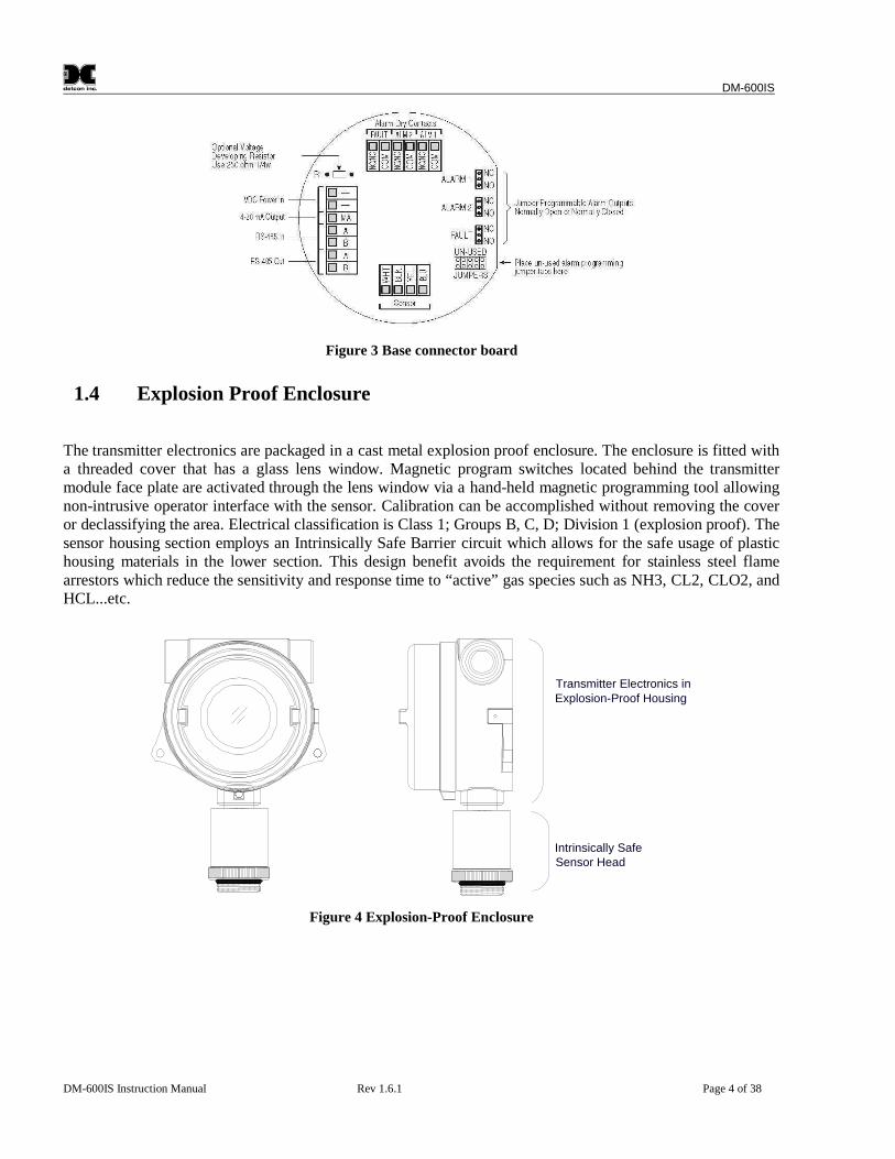
The base connector board is mounted in the explosion proof enclosure and includes: the mating connector forthe control circuit, reverse input and secondary transient suppression, input filter, alarm relays, luglessterminals for all field wiring, and a terminal strip for storing unused programming jumper tabs. The alarmrelays are contact rated 5 amps @ 125 VAC, 5 amps @ 30 VDC and coil rated at 24 VDC. Gold platedprogram jumpers are used to select either the normally open or normally closed relay contacts.
NOTE: The yellow wire should not be connected and should be cut off!
DM-600IS
DM-600IS Instruction Manual Rev 1.6.1 Page 4 of 38
Figure 3 Base connector board
1.4 Explosion Proof Enclosure
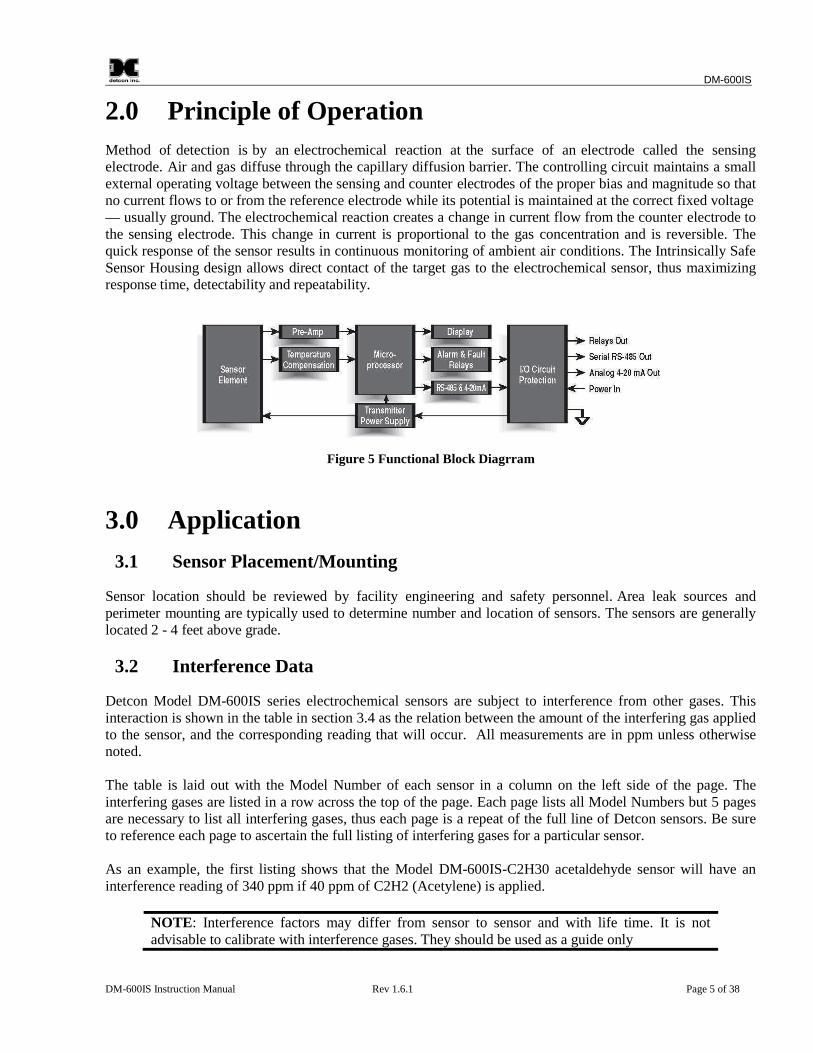
The transmitter electronics are packaged in a cast metal explosion proof enclosure. The enclosure is fitted witha threaded cover that has a glass lens window. Magnetic program switches located behind the transmittermodule face plate are activated through the lens window via a hand-held magnetic programming tool allowingnon-intrusive operator interface with the sensor. Calibration can be accomplished without removing the coveror declassifying the area. Electrical classification is Class 1; Groups B, C, D; Division 1 (explosion proof). Thesensor housing section employs an Intrinsically Safe Barrier circuit which allows for the safe usage of plastichousing materials in the lower section. This design benefit avoids the requirement for stainless steel flamearrestors which reduce the sensitivity and response time to “active” gas species such as NH3, CL2, CLO2, andHCL...etc.
Transmitter Electronics inExplosion-Proof Housing
Intrinsically SafeSensor Head
Figure 4 Explosion-Proof Enclosure
DM-600IS
DM-600IS Instruction Manual Rev 1.6.1 Page 5 of 38
2.0 Principle of Operation
Method of detection is by an electrochemical reaction at the surface of an electrode called the sensingelectrode. Air and gas diffuse through the capillary diffusion barrier. The controlling circuit maintains a smallexternal operating voltage between the sensing and counter electrodes of the proper bias and magnitude so thatno current flows to or from the reference electrode while its potential is maintained at the correct fixed voltage— usually ground. The electrochemical reaction creates a change in current flow from the counter electrode tothe sensing electrode. This change in current is proportional to the gas concentration and is reversible. Thequick response of the sensor results in continuous monitoring of ambient air conditions. The Intrinsically SafeSensor Housing design allows direct contact of the target gas to the electrochemical sensor, thus maximizingresponse time, detectability and repeatability.
Figure 5 Functional Block Diagrram
3.0 Application
3.1 Sensor Placement/Mounting
Sensor location should be reviewed by facility engineering and safety personnel. Area leak sources andperimeter mounting are typically used to determine number and location of sensors. The sensors are generallylocated 2 - 4 feet above grade.
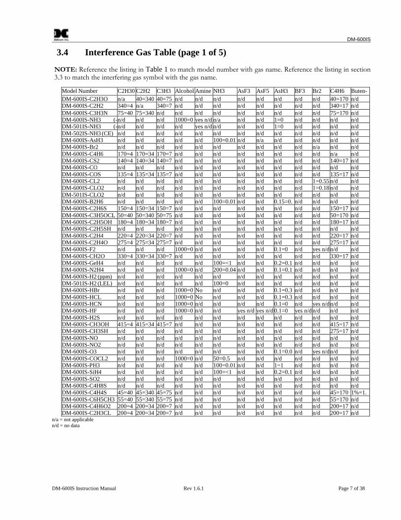
3.2 Interference Data
Detcon Model DM-600IS series electrochemical sensors are subject to interference from other gases. Thisinteraction is shown in the table in section 3.4 as the relation between the amount of the interfering gas appliedto the sensor, and the corresponding reading that will occur. All measurements are in ppm unless otherwisenoted.
The table is laid out with the Model Number of each sensor in a column on the left side of the page. Theinterfering gases are listed in a row across the top of the page. Each page lists all Model Numbers but 5 pagesare necessary to list all interfering gases, thus each page is a repeat of the full line of Detcon sensors. Be sureto reference each page to ascertain the full listing of interfering gases for a particular sensor.
As an example, the first listing shows that the Model DM-600IS-C2H30 acetaldehyde sensor will have aninterference reading of 340 ppm if 40 ppm of C2H2 (Acetylene) is applied.
NOTE: Interference factors may differ from sensor to sensor and with life time. It is notadvisable to calibrate with interference gases. They should be used as a guide only
DM-600IS
DM-600IS Instruction Manual Rev 1.6.1 Page 6 of 38
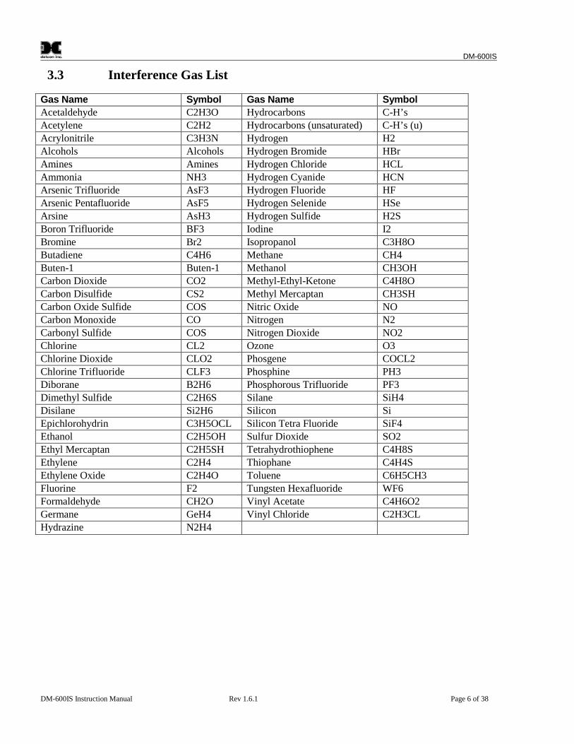
3.3 Interference Gas List
Gas Name Symbol Gas Name Symbol
Acetaldehyde C2H3O Hydrocarbons C-H’s
Acetylene C2H2 Hydrocarbons (unsaturated) C-H’s (u)
Acrylonitrile C3H3N Hydrogen H2
Alcohols Alcohols Hydrogen Bromide HBr
Amines Amines Hydrogen Chloride HCL
Ammonia NH3 Hydrogen Cyanide HCN
Arsenic Trifluoride AsF3 Hydrogen Fluoride HF
Arsenic Pentafluoride AsF5 Hydrogen Selenide HSe
Arsine AsH3 Hydrogen Sulfide H2S
Boron Trifluoride BF3 Iodine I2
Bromine Br2 Isopropanol C3H8O
Butadiene C4H6 Methane CH4
Buten-1 Buten-1 Methanol CH3OH
Carbon Dioxide CO2 Methyl-Ethyl-Ketone C4H8O
Carbon Disulfide CS2 Methyl Mercaptan CH3SH
Carbon Oxide Sulfide COS Nitric Oxide NO
Carbon Monoxide CO Nitrogen N2
Carbonyl Sulfide COS Nitrogen Dioxide NO2
Chlorine CL2 Ozone O3
Chlorine Dioxide CLO2 Phosgene COCL2
Chlorine Trifluoride CLF3 Phosphine PH3
Diborane B2H6 Phosphorous Trifluoride PF3
Dimethyl Sulfide C2H6S Silane SiH4
Disilane Si2H6 Silicon Si
Epichlorohydrin C3H5OCL Silicon Tetra Fluoride SiF4
Ethanol C2H5OH Sulfur Dioxide SO2
Ethyl Mercaptan C2H5SH Tetrahydrothiophene C4H8S
Ethylene C2H4 Thiophane C4H4S
Ethylene Oxide C2H4O Toluene C6H5CH3
Fluorine F2 Tungsten Hexafluoride WF6
Formaldehyde CH2O Vinyl Acetate C4H6O2
Germane GeH4 Vinyl Chloride C2H3CL
Hydrazine N2H4
DM-600IS
DM-600IS Instruction Manual Rev 1.6.1 Page 7 of 38
3.4 Interference Gas Table (page 1 of 5)
NOTE: Reference the listing in Table 1 to match model number with gas name. Reference the listing in section3.3 to match the interfering gas symbol with the gas name.
Model Number C2H30 C2H2 C3H3N
Alcohols
Amines
NH3 AsF3 AsF5 AsH3 BF3 Br2 C4H6 Buten-1DM-600IS-C2H3O n/a 40=340 40=75 n/d n/d n/d n/d n/d n/d n/d n/d 40=170 n/d
DM-600IS-C2H2 340=4 n/a 340=7 n/d n/d n/d n/d n/d n/d n/d n/d 340=17 n/dDM-600IS-C3H3N 75=40 75=340 n/d n/d n/d n/d n/d n/d n/d n/d n/d 75=170 n/dDM-600IS-NH3 (-n/d n/d n/d 1000=0 yes n/d n/a n/d n/d 1=0 n/d n/d n/d n/dDM-501IS-NH3 (-n/d n/d n/d n/d yes n/d n/d n/d n/d 1=0 n/d n/d n/d n/dDM-502IS-NH3 (CE) n/d n/d n/d n/d n/d n/d n/d n/d n/d n/d n/d n/d n/dDM-600IS-AsH3 n/d n/d n/d n/d n/d 100=0.01 n/d n/a n/d n/d n/d n/d n/dDM-600IS-Br2 n/d n/d n/d n/d n/d n/d n/d n/d n/d n/d n/a n/d n/dDM-600IS-C4H6 170=4 170=34 170=7 n/d n/d n/d n/d n/d n/d n/d n/d n/a n/dDM-600IS-CS2 140=4 140=34 140=7 n/d n/d n/d n/d n/d n/d n/d n/d 140=17 n/dDM-600IS-CO n/d n/d n/d n/d n/d n/d n/d n/d n/d n/d n/d n/d n/dDM-600IS-COS 135=4 135=34 135=7 n/d n/d n/d n/d n/d n/d n/d n/d 135=17 n/dDM-600IS-CL2 n/d n/d n/d n/d n/d n/d n/d n/d n/d n/d 1=0.55 n/d n/dDM-600IS-CLO2 n/d n/d n/d n/d n/d n/d n/d n/d n/d n/d 1=0.18 n/d n/dDM-501IS-CLO2 n/d n/d n/d n/d n/d n/d n/d n/d n/d n/d n/d n/d n/dDM-600IS-B2H6 n/d n/d n/d n/d n/d 100=0.01 n/d n/d 0.15=0. n/d n/d n/d n/dDM-600IS-C2H6S 150=4 150=34 150=7 n/d n/d n/d n/d n/d n/d n/d n/d 150=17 n/dDM-600IS-C3H5OCL 50=40 50=340 50=75 n/d n/d n/d n/d n/d n/d n/d n/d 50=170 n/dDM-600IS-C2H5OH 180=4 180=34 180=7 n/d n/d n/d n/d n/d n/d n/d n/d 180=17 n/dDM-600IS-C2H5SH n/d n/d n/d n/d n/d n/d n/d n/d n/d n/d n/d n/d n/dDM-600IS-C2H4 220=4 220=34 220=7 n/d n/d n/d n/d n/d n/d n/d n/d 220=17 n/dDM-600IS-C2H4O 275=4 275=34 275=7 n/d n/d n/d n/d n/d n/d n/d n/d 275=17 n/dDM-600IS-F2 n/d n/d n/d 1000=0 n/d n/d n/d n/d 0.1=0 n/d yes n/d n/d n/dDM-600IS-CH2O 330=4 330=34 330=7 n/d n/d n/d n/d n/d n/d n/d n/d 330=17 n/dDM-600IS-GeH4 n/d n/d n/d n/d n/d 100=<1 n/d n/d 0.2=0.1 n/d n/d n/d n/dDM-600IS-N2H4 n/d n/d n/d 1000=0 n/d 200=0.04 n/d n/d 0.1=0.1 n/d n/d n/d n/dDM-600IS-H2 (ppm) n/d n/d n/d n/d n/d n/d n/d n/d n/d n/d n/d n/d n/dDM-501IS-H2 (LEL) n/d n/d n/d n/d n/d 100=0 n/d n/d n/d n/d n/d n/d n/dDM-600IS-HBr n/d n/d n/d 1000=0 No n/d n/d n/d 0.1=0.3 n/d n/d n/d n/dDM-600IS-HCL n/d n/d n/d 1000=0 No n/d n/d n/d 0.1=0.3 n/d n/d n/d n/dDM-600IS-HCN n/d n/d n/d 1000=0 n/d n/d n/d n/d 0.1=0 n/d yes n/d n/d n/dDM-600IS-HF n/d n/d n/d 1000=0 n/d n/d yes n/d yes n/d 0.1=0 yes n/d n/d n/d n/dDM-600IS-H2S n/d n/d n/d n/d n/d n/d n/d n/d n/d n/d n/d n/d n/dDM-600IS-CH3OH 415=4 415=34 415=7 n/d n/d n/d n/d n/d n/d n/d n/d 415=17 n/dDM-600IS-CH3SH n/d n/d n/d n/d n/d n/d n/d n/d n/d n/d n/d 275=17 n/dDM-600IS-NO n/d n/d n/d n/d n/d n/d n/d n/d n/d n/d n/d n/d n/dDM-600IS-NO2 n/d n/d n/d n/d n/d n/d n/d n/d n/d n/d n/d n/d n/dDM-600IS-O3 n/d n/d n/d n/d n/d n/d n/d n/d 0.1=0.0 n/d yes n/d n/d n/dDM-600IS-COCL2 n/d n/d n/d 1000=0 n/d 50=0.5 n/d n/d n/d n/d n/d n/d n/dDM-600IS-PH3 n/d n/d n/d n/d n/d 100=0.01 n/d n/d 1=1 n/d n/d n/d n/dDM-600IS-SiH4 n/d n/d n/d n/d n/d 100=<1 n/d n/d 0.2=0.1 n/d n/d n/d n/dDM-600IS-SO2 n/d n/d n/d n/d n/d n/d n/d n/d n/d n/d n/d n/d n/dDM-600IS-C4H8S n/d n/d n/d n/d n/d n/d n/d n/d n/d n/d n/d n/d n/dDM-600IS-C4H4S 45=40 45=340 45=75 n/d n/d n/d n/d n/d n/d n/d n/d 45=170 1%=1.DM-600IS-C6H5CH3 55=40 55=340 55=75 n/d n/d n/d n/d n/d n/d n/d n/d 55=170 n/dDM-600IS-C4H6O2 200=4 200=34 200=7 n/d n/d n/d n/d n/d n/d n/d n/d 200=17 n/dDM-600IS-C2H3CL 200=4 200=34 200=7 n/d n/d n/d n/d n/d n/d n/d n/d 200=17 n/d
n/a = not applicablen/d = no data
DM-600IS
DM-600IS Instruction Manual Rev 1.6.1 Page 8 of 38
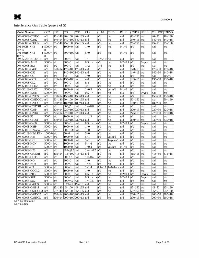
Interference Gas Table (page 2 of 5)
Model Number CO2 CS2 CO COS CL2 CL02 CLF3 B2H6 C2H6S Si2H6 C3H5OCL
C2H5OHDM-600IS-C2H3O n/d 40=140 40=100 40=135 n/d n/d n/d n/d 40=150 n/d 40=50 40=180
DM-600IS-C2H2 n/d 340=14 340=100 340=13 n/d n/d n/d n/d 340=15 n/d 340=50 340=18DM-600IS-C3H3N n/d 75=140 75=100 75=135 n/d n/d n/d n/d 75=150 n/d 75=50 75=180DM-600IS-NH3 (-20°C)
5000=0
n/d 1000=0 n/d 1=0 n/d n/d 0.1=0 n/d n/d n/d n/d
DM-501IS-NH3 (-40°C)
5000=0
n/d 300=100 n/d 5=0 n/d n/d 0.1=0 n/d n/d n/d n/d
DM-502IS-NH3 (CE) n/d n/d 300=8 n/d 1=1 10%=15n/d n/d n/d n/d n/d n/dDM-600IS-AsH3 5000= n/d 300=0 n/d 0.5 = -n/d n/d 0.2=0.1 n/d 5=yes n/d n/dDM-600IS-Br2 n/d n/d 300=0 n/d 1=2 1=6 n/d n/d n/d n/d n/a n/dDM-600IS-C4H6 n/d 170=14 170=100 170=13 n/d n/d n/d n/d 170=15 n/d 170=50 170=18DM-600IS-CS2 n/d n/a 140=100 140=13 n/d n/d n/d n/d 140=15 n/d 140=50 140=18DM-600IS-CO n/d n/d n/a n/d 1=0 n/d n/d n/d n/d n/d n/d 200=0DM-600IS-COS n/d 135=14 135=100 n/a n/d n/d n/d n/d 135=15 n/d 135=50 135=18DM-600IS-CL2 n/d n/d 300=0 n/d n/a n/d n/d n/d n/d n/d n/d n/dDM-600IS-CLO2 n/d n/d 300=0 n/d 3=1 n/a n/d n/d n/d n/d n/d n/dDM-501IS-CLO2 5000= n/d 1000=0 n/d 1=0.9 n/a yes n/d 0.1=0 n/d n/d n/d n/dDM-600IS-B2H6 5000= n/d 300=0 n/d 0.5 = -n/d n/d n/a n/d 5=yes n/d n/dDM-600IS-C2H6S n/d 150=14 150=100 150=13 n/d n/d n/d n/d n/a n/d 150=50 150=18DM-600IS-C3H5OCL n/d 50=140 50=100 50=135 n/d n/d n/d n/d 50=150 n/d n/a 50=180DM-600IS-C2H5OH n/d 180=14 180=100 180=13 n/d n/d n/d n/d 180=15 n/d 180=50 n/aDM-600IS-C2H5SH n/d n/d 300≤5 n/d 1 = -0.6 n/d n/d n/d n/d n/d n/d n/dDM-600IS-C2H4 n/d 220=14 220=100 220=13 n/d n/d n/d n/d 220=15 n/d 220=50 220=18DM-600IS-C2H4O n/d 275=14 275=100 275=13 n/d n/d n/d n/d 275=15 n/d 275=50 275=18DM-600IS-F2 5000= n/d 1000=0 n/d 1=1.3 n/d n/d n/d n/d n/d n/d n/dDM-600IS-CH2O n/d 330=14 330=100 330=13 n/d n/d n/d n/d 330=15 n/d 330=50 330=18DM-600IS-GeH4 5000= n/d 300=0 n/d 0.5 = -n/d n/d 0.2=0.1 n/d 5=yes n/d n/dDM-600IS-N2H4 5000= n/d 1000=0 n/d 1=0 n/d n/d n/d n/d n/d n/d n/dDM-600IS-H2 (ppm) n/d n/d 300=<30 n/d 1=0 n/d n/d n/d n/d n/d n/d n/dDM-601IS-H2 (LEL) 1000-0 n/d 50=6 n/d 5=0 n/d n/d n/d n/d n/d n/d n/dDM-600IS-HBr 5000= n/d 1000=0 n/d 5=1 n/d yes n/d n/d n/d n/d n/d n/dDM-600IS-HCL 5000= n/d 1000=0 n/d 5=1 n/d 1=yes n/d n/d n/d n/d n/d n/dDM-600IS-HCN 5000= n/d 1000=0 n/d 5 = -1 n/d n/d n/d n/d n/d n/d n/dDM-600IS-HF 5000= n/d 1000=0 n/d 1=0.4 n/d yes n/d 0.1=0 n/d n/d n/d n/dDM-600IS-H2S n/d n/d 300=≤1.5 n/d 1 = ≈ -0.2 n/d n/d n/d n/d n/d n/d n/dDM-600IS-CH3OH n/d 415=14 415=100 415=13 n/d n/d n/d n/d 415=15 n/d 415=50 415=18DM-600IS-CH3SH n/d n/d 300 ≤ 3 n/d 1 = -0.4 n/d n/d n/d n/d n/d n/d n/dDM-600IS-NO n/d n/d 300=0 n/d 1=0 n/d n/d n/d n/d n/d n/d n/dDM-600IS-NO2 n/d n/d 300=0 n/d 1= ≈1 n/d n/d n/d n/d n/d n/d n/dDM-600IS-O3 5000= n/d 300=0 n/d 1=1.4 0.1=0.1 1=1(theor n/d n/d n/d n/d n/dDM-600IS-COCL2 5000= n/d 1000=0 n/d 1=0 n/d n/d n/d n/d n/d n/d n/dDM-600IS-PH3 5000= n/d 300=0 n/d 0.5 = -n/d n/d 0.2=0.1 n/d 5=yes n/d n/dDM-600IS-SiH4 5000= n/d 300=0 n/d 0.5 = -n/d n/d 0.2=0.1 n/d 5=yes n/d n/dDM-600IS-SO2 n/d n/d 300=<5 n/d 1=<0.5 n/d n/d n/d n/d n/d n/d n/dDM-600IS-C4H8S 5000= n/d 0.1%=1. 1%=10 n/d n/d n/d n/d n/d n/d n/d n/dDM-600IS-C4H4S n/d 45=140 45=100 45=135 n/d n/d n/d n/d 45=150 n/d 45=50 45=180DM-600IS-C6H5CH3 n/d 55=140 55=100 55=135 n/d n/d n/d n/d 55=150 n/d 55=50 55=180DM-600IS-C4H6O2 n/d 200=14 200=100 200=13 n/d n/d n/d n/d 200=15 n/d 200=50 200=18DM-600IS-C2H3CL n/d 200=14 200=100 200=13 n/d n/d n/d n/d 200=15 n/d 200=50 200=18
n/a = not applicablen/d = no data
DM-600IS
DM-600IS Instruction Manual Rev 1.6.1 Page 9 of 38
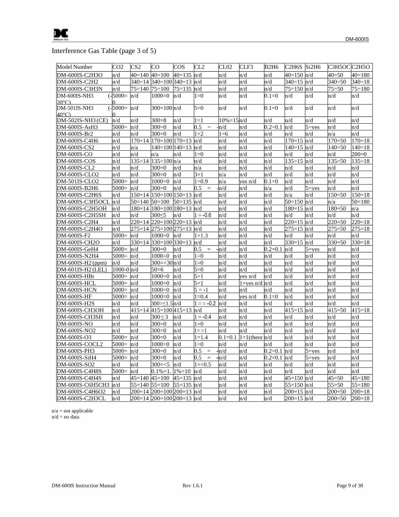
Interference Gas Table (page 3 of 5)
Model Number CO2 CS2 CO COS CL2 CL02 CLF3 B2H6 C2H6S Si2H6 C3H5OCL
C2H5OHDM-600IS-C2H3O n/d 40=140 40=100 40=135 n/d n/d n/d n/d 40=150 n/d 40=50 40=180
DM-600IS-C2H2 n/d 340=14 340=100 340=13 n/d n/d n/d n/d 340=15 n/d 340=50 340=18DM-600IS-C3H3N n/d 75=140 75=100 75=135 n/d n/d n/d n/d 75=150 n/d 75=50 75=180DM-600IS-NH3 (-20°C)
5000=0
n/d 1000=0 n/d 1=0 n/d n/d 0.1=0 n/d n/d n/d n/d
DM-501IS-NH3 (-40°C)
5000=0
n/d 300=100 n/d 5=0 n/d n/d 0.1=0 n/d n/d n/d n/d
DM-502IS-NH3 (CE) n/d n/d 300=8 n/d 1=1 10%=15n/d n/d n/d n/d n/d n/dDM-600IS-AsH3 5000= n/d 300=0 n/d 0.5 = -n/d n/d 0.2=0.1 n/d 5=yes n/d n/dDM-600IS-Br2 n/d n/d 300=0 n/d 1=2 1=6 n/d n/d n/d n/d n/a n/dDM-600IS-C4H6 n/d 170=14 170=100 170=13 n/d n/d n/d n/d 170=15 n/d 170=50 170=18DM-600IS-CS2 n/d n/a 140=100 140=13 n/d n/d n/d n/d 140=15 n/d 140=50 140=18DM-600IS-CO n/d n/d n/a n/d 1=0 n/d n/d n/d n/d n/d n/d 200=0DM-600IS-COS n/d 135=14 135=100 n/a n/d n/d n/d n/d 135=15 n/d 135=50 135=18DM-600IS-CL2 n/d n/d 300=0 n/d n/a n/d n/d n/d n/d n/d n/d n/dDM-600IS-CLO2 n/d n/d 300=0 n/d 3=1 n/a n/d n/d n/d n/d n/d n/dDM-501IS-CLO2 5000= n/d 1000=0 n/d 1=0.9 n/a yes n/d 0.1=0 n/d n/d n/d n/dDM-600IS-B2H6 5000= n/d 300=0 n/d 0.5 = -n/d n/d n/a n/d 5=yes n/d n/dDM-600IS-C2H6S n/d 150=14 150=100 150=13 n/d n/d n/d n/d n/a n/d 150=50 150=18DM-600IS-C3H5OCL n/d 50=140 50=100 50=135 n/d n/d n/d n/d 50=150 n/d n/a 50=180DM-600IS-C2H5OH n/d 180=14 180=100 180=13 n/d n/d n/d n/d 180=15 n/d 180=50 n/aDM-600IS-C2H5SH n/d n/d 300≤5 n/d 1 = -0.6 n/d n/d n/d n/d n/d n/d n/dDM-600IS-C2H4 n/d 220=14 220=100 220=13 n/d n/d n/d n/d 220=15 n/d 220=50 220=18DM-600IS-C2H4O n/d 275=14 275=100 275=13 n/d n/d n/d n/d 275=15 n/d 275=50 275=18DM-600IS-F2 5000= n/d 1000=0 n/d 1=1.3 n/d n/d n/d n/d n/d n/d n/dDM-600IS-CH2O n/d 330=14 330=100 330=13 n/d n/d n/d n/d 330=15 n/d 330=50 330=18DM-600IS-GeH4 5000= n/d 300=0 n/d 0.5 = -n/d n/d 0.2=0.1 n/d 5=yes n/d n/dDM-600IS-N2H4 5000= n/d 1000=0 n/d 1=0 n/d n/d n/d n/d n/d n/d n/dDM-600IS-H2 (ppm) n/d n/d 300=<30 n/d 1=0 n/d n/d n/d n/d n/d n/d n/dDM-601IS-H2 (LEL) 1000-0 n/d 50=6 n/d 5=0 n/d n/d n/d n/d n/d n/d n/dDM-600IS-HBr 5000= n/d 1000=0 n/d 5=1 n/d yes n/d n/d n/d n/d n/d n/dDM-600IS-HCL 5000= n/d 1000=0 n/d 5=1 n/d 1=yes n/d n/d n/d n/d n/d n/dDM-600IS-HCN 5000= n/d 1000=0 n/d 5 = -1 n/d n/d n/d n/d n/d n/d n/dDM-600IS-HF 5000= n/d 1000=0 n/d 1=0.4 n/d yes n/d 0.1=0 n/d n/d n/d n/dDM-600IS-H2S n/d n/d 300=≤1.5 n/d 1 = ≈ -0.2 n/d n/d n/d n/d n/d n/d n/dDM-600IS-CH3OH n/d 415=14 415=100 415=13 n/d n/d n/d n/d 415=15 n/d 415=50 415=18DM-600IS-CH3SH n/d n/d 300 ≤ 3 n/d 1 = -0.4 n/d n/d n/d n/d n/d n/d n/dDM-600IS-NO n/d n/d 300=0 n/d 1=0 n/d n/d n/d n/d n/d n/d n/dDM-600IS-NO2 n/d n/d 300=0 n/d 1= ≈1 n/d n/d n/d n/d n/d n/d n/dDM-600IS-O3 5000= n/d 300=0 n/d 1=1.4 0.1=0.1 1=1(theor n/d n/d n/d n/d n/dDM-600IS-COCL2 5000= n/d 1000=0 n/d 1=0 n/d n/d n/d n/d n/d n/d n/dDM-600IS-PH3 5000= n/d 300=0 n/d 0.5 = -n/d n/d 0.2=0.1 n/d 5=yes n/d n/dDM-600IS-SiH4 5000= n/d 300=0 n/d 0.5 = -n/d n/d 0.2=0.1 n/d 5=yes n/d n/dDM-600IS-SO2 n/d n/d 300=<5 n/d 1=<0.5 n/d n/d n/d n/d n/d n/d n/dDM-600IS-C4H8S 5000= n/d 0.1%=1. 1%=10 n/d n/d n/d n/d n/d n/d n/d n/dDM-600IS-C4H4S n/d 45=140 45=100 45=135 n/d n/d n/d n/d 45=150 n/d 45=50 45=180DM-600IS-C6H5CH3 n/d 55=140 55=100 55=135 n/d n/d n/d n/d 55=150 n/d 55=50 55=180DM-600IS-C4H6O2 n/d 200=14 200=100 200=13 n/d n/d n/d n/d 200=15 n/d 200=50 200=18DM-600IS-C2H3CL n/d 200=14 200=100 200=13 n/d n/d n/d n/d 200=15 n/d 200=50 200=18
n/a = not applicablen/d = no data

DM-600IS
DM-600IS Instruction Manual Rev 1.6.1 Page 10 of 38
Interference Gas Table (page 4 of 5)
Model Number CO2 CS2 CO COS CL2 CL02 CLF3 B2H6 C2H6S Si2H6 C3H5OCL
C2H5OHDM-600IS-C2H3O n/d 40=140 40=100 40=135 n/d n/d n/d n/d 40=150 n/d 40=50 40=180
DM-600IS-C2H2 n/d 340=14 340=100 340=13 n/d n/d n/d n/d 340=15 n/d 340=50 340=18DM-600IS-C3H3N n/d 75=140 75=100 75=135 n/d n/d n/d n/d 75=150 n/d 75=50 75=180DM-600IS-NH3 (-20°C)
5000=0
n/d 1000=0 n/d 1=0 n/d n/d 0.1=0 n/d n/d n/d n/d
DM-501IS-NH3 (-40°C)
5000=0
n/d 300=100 n/d 5=0 n/d n/d 0.1=0 n/d n/d n/d n/d
DM-502IS-NH3 (CE) n/d n/d 300=8 n/d 1=1 10%=15n/d n/d n/d n/d n/d n/dDM-600IS-AsH3 5000= n/d 300=0 n/d 0.5 = -n/d n/d 0.2=0.1 n/d 5=yes n/d n/dDM-600IS-Br2 n/d n/d 300=0 n/d 1=2 1=6 n/d n/d n/d n/d n/a n/dDM-600IS-C4H6 n/d 170=14 170=100 170=13 n/d n/d n/d n/d 170=15 n/d 170=50 170=18DM-600IS-CS2 n/d n/a 140=100 140=13 n/d n/d n/d n/d 140=15 n/d 140=50 140=18DM-600IS-CO n/d n/d n/a n/d 1=0 n/d n/d n/d n/d n/d n/d 200=0DM-600IS-COS n/d 135=14 135=100 n/a n/d n/d n/d n/d 135=15 n/d 135=50 135=18DM-600IS-CL2 n/d n/d 300=0 n/d n/a n/d n/d n/d n/d n/d n/d n/dDM-600IS-CLO2 n/d n/d 300=0 n/d 3=1 n/a n/d n/d n/d n/d n/d n/dDM-501IS-CLO2 5000= n/d 1000=0 n/d 1=0.9 n/a yes n/d 0.1=0 n/d n/d n/d n/dDM-600IS-B2H6 5000= n/d 300=0 n/d 0.5 = -n/d n/d n/a n/d 5=yes n/d n/dDM-600IS-C2H6S n/d 150=14 150=100 150=13 n/d n/d n/d n/d n/a n/d 150=50 150=18DM-600IS-C3H5OCL n/d 50=140 50=100 50=135 n/d n/d n/d n/d 50=150 n/d n/a 50=180DM-600IS-C2H5OH n/d 180=14 180=100 180=13 n/d n/d n/d n/d 180=15 n/d 180=50 n/aDM-600IS-C2H5SH n/d n/d 300≤5 n/d 1 = -0.6 n/d n/d n/d n/d n/d n/d n/dDM-600IS-C2H4 n/d 220=14 220=100 220=13 n/d n/d n/d n/d 220=15 n/d 220=50 220=18DM-600IS-C2H4O n/d 275=14 275=100 275=13 n/d n/d n/d n/d 275=15 n/d 275=50 275=18DM-600IS-F2 5000= n/d 1000=0 n/d 1=1.3 n/d n/d n/d n/d n/d n/d n/dDM-600IS-CH2O n/d 330=14 330=100 330=13 n/d n/d n/d n/d 330=15 n/d 330=50 330=18DM-600IS-GeH4 5000= n/d 300=0 n/d 0.5 = -n/d n/d 0.2=0.1 n/d 5=yes n/d n/dDM-600IS-N2H4 5000= n/d 1000=0 n/d 1=0 n/d n/d n/d n/d n/d n/d n/dDM-600IS-H2 (ppm) n/d n/d 300=<30 n/d 1=0 n/d n/d n/d n/d n/d n/d n/dDM-601IS-H2 (LEL) 1000-0 n/d 50=6 n/d 5=0 n/d n/d n/d n/d n/d n/d n/dDM-600IS-HBr 5000= n/d 1000=0 n/d 5=1 n/d yes n/d n/d n/d n/d n/d n/dDM-600IS-HCL 5000= n/d 1000=0 n/d 5=1 n/d 1=yes n/d n/d n/d n/d n/d n/dDM-600IS-HCN 5000= n/d 1000=0 n/d 5 = -1 n/d n/d n/d n/d n/d n/d n/dDM-600IS-HF 5000= n/d 1000=0 n/d 1=0.4 n/d yes n/d 0.1=0 n/d n/d n/d n/dDM-600IS-H2S n/d n/d 300=≤1.5 n/d 1 = ≈ -0.2 n/d n/d n/d n/d n/d n/d n/dDM-600IS-CH3OH n/d 415=14 415=100 415=13 n/d n/d n/d n/d 415=15 n/d 415=50 415=18DM-600IS-CH3SH n/d n/d 300 ≤ 3 n/d 1 = -0.4 n/d n/d n/d n/d n/d n/d n/dDM-600IS-NO n/d n/d 300=0 n/d 1=0 n/d n/d n/d n/d n/d n/d n/dDM-600IS-NO2 n/d n/d 300=0 n/d 1= ≈1 n/d n/d n/d n/d n/d n/d n/dDM-600IS-O3 5000= n/d 300=0 n/d 1=1.4 0.1=0.1 1=1(theor n/d n/d n/d n/d n/dDM-600IS-COCL2 5000= n/d 1000=0 n/d 1=0 n/d n/d n/d n/d n/d n/d n/dDM-600IS-PH3 5000= n/d 300=0 n/d 0.5 = -n/d n/d 0.2=0.1 n/d 5=yes n/d n/dDM-600IS-SiH4 5000= n/d 300=0 n/d 0.5 = -n/d n/d 0.2=0.1 n/d 5=yes n/d n/dDM-600IS-SO2 n/d n/d 300=<5 n/d 1=<0.5 n/d n/d n/d n/d n/d n/d n/dDM-600IS-C4H8S 5000= n/d 0.1%=1. 1%=10 n/d n/d n/d n/d n/d n/d n/d n/dDM-600IS-C4H4S n/d 45=140 45=100 45=135 n/d n/d n/d n/d 45=150 n/d 45=50 45=180DM-600IS-C6H5CH3 n/d 55=140 55=100 55=135 n/d n/d n/d n/d 55=150 n/d 55=50 55=180DM-600IS-C4H6O2 n/d 200=14 200=100 200=13 n/d n/d n/d n/d 200=15 n/d 200=50 200=18DM-600IS-C2H3CL n/d 200=14 200=100 200=13 n/d n/d n/d n/d 200=15 n/d 200=50 200=18
n/a = not applicablen/d = no data
DM-600IS
DM-600IS Instruction Manual Rev 1.6.1 Page 11 of 38
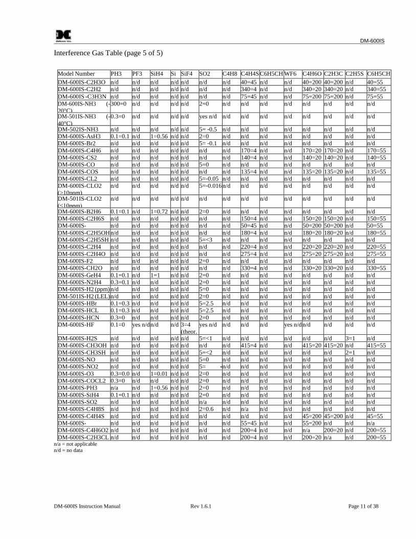
Interference Gas Table (page 5 of 5)
Model Number PH3 PF3 SiH4 Si SiF4 SO2 C4H8S
C4H4S C6H5CH3
WF6 C4H6O2
C2H3CL
C2H5SH
C6H5CH3DM-600IS-C2H3O n/d n/d n/d n/d n/d n/d n/d 40=45 n/d n/d 40=200 40=200 n/d 40=55
DM-600IS-C2H2 n/d n/d n/d n/d n/d n/d n/d 340=4 n/d n/d 340=20 340=20 n/d 340=55DM-600IS -C3H3N n/d n/d n/d n/d n/d n/d n/d 75=45 n/d n/d 75=200 75=200 n/d 75=55DM-600IS-NH3 (-20°C)
300=0 n/d n/d n/d n/d 2=0 n/d n/d n/d n/d n/d n/d n/d n/d
DM-501IS-NH3 (-40°C)
0.3=0 n/d n/d n/d n/d yes n/d n/d n/d n/d n/d n/d n/d n/d n/d
DM-502IS-NH3 n/d n/d n/d n/d n/d 5= -0.5 n/d n/d n/d n/d n/d n/d n/d n/dDM-600IS-AsH3 0.1=0.1 n/d 1=0.56 n/d n/d 2=0 n/d n/d n/d n/d n/d n/d n/d n/dDM-600IS-Br2 n/d n/d n/d n/d n/d 5= -0.1 n/d n/d n/d n/d n/d n/d n/d n/dDM-600IS-C4H6 n/d n/d n/d n/d n/d n/d n/d 170=4 n/d n/d 170=20 170=20 n/d 170=55DM-600IS-CS2 n/d n/d n/d n/d n/d n/d n/d 140=4 n/d n/d 140=20 140=20 n/d 140=55DM-600IS-CO n/d n/d n/d n/d n/d 5=0 n/d n/d n/d n/d n/d n/d n/d n/dDM-600IS-COS n/d n/d n/d n/d n/d n/d n/d 135=4 n/d n/d 135=20 135=20 n/d 135=55DM-600IS-CL2 n/d n/d n/d n/d n/d 5=-0.05 n/d n/d n/d n/d n/d n/d n/d n/dDM-600IS-CLO2(>10ppm)
n/d n/d n/d n/d n/d 5=-0.016 n/d n/d n/d n/d n/d n/d n/d n/d
DM-501IS-CLO2(≤10ppm)
n/d n/d n/d n/d n/d n/d n/d n/d n/d n/d n/d n/d n/d n/d
DM-600IS-B2H6 0.1=0.1 n/d 1=0.72 n/d n/d 2=0 n/d n/d n/d n/d n/d n/d n/d n/dDM-600IS-C2H6S n/d n/d n/d n/d n/d n/d n/d 150=4 n/d n/d 150=20 150=20 n/d 150=55DM-600IS- n/d n/d n/d n/d n/d n/d n/d 50=45 n/d n/d 50=200 50=200 n/d 50=55DM-600IS-C2H5OH n/d n/d n/d n/d n/d n/d n/d 180=4 n/d n/d 180=20 180=20 n/d 180=55DM-600IS-C2H5SH n/d n/d n/d n/d n/d 5=<3 n/d n/d n/d n/d n/d n/d n/d n/dDM-600IS-C2H4 n/d n/d n/d n/d n/d n/d n/d 220=4 n/d n/d 220=20 220=20 n/d 220=55DM-600IS-C2H4O n/d n/d n/d n/d n/d n/d n/d 275=4 n/d n/d 275=20 275=20 n/d 275=55DM-600IS-F2 n/d n/d n/d n/d n/d 2=0 n/d n/d n/d n/d n/d n/d n/d n/dDM-600IS-CH2O n/d n/d n/d n/d n/d n/d n/d 330=4 n/d n/d 330=20 330=20 n/d 330=55DM-600IS-GeH4 0.1=0.1 n/d 1=1 n/d n/d 2=0 n/d n/d n/d n/d n/d n/d n/d n/dDM-600IS-N2H4 0.3=0.1 n/d n/d n/d n/d 2=0 n/d n/d n/d n/d n/d n/d n/d n/dDM-600IS-H2 (ppm) n/d n/d n/d n/d n/d 5=0 n/d n/d n/d n/d n/d n/d n/d n/dDM-501IS-H2 (LEL)n/d n/d n/d n/d n/d 2=0 n/d n/d n/d n/d n/d n/d n/d n/dDM-600IS-HBr 0.1=0.3 n/d n/d n/d n/d 5=2.5 n/d n/d n/d n/d n/d n/d n/d n/dDM-600IS-HCL 0.1=0.3 n/d n/d n/d n/d 5=2.5 n/d n/d n/d n/d n/d n/d n/d n/dDM-600IS-HCN 0.3=0 n/d n/d n/d n/d 2=0 n/d n/d n/d n/d n/d n/d n/d n/dDM-600IS-HF 0.1=0 yes n/d n/d n/d 3=4
(theor.yes n/d n/d n/d n/d yes n/d n/d n/d n/d n/d
DM-600IS-H2S n/d n/d n/d n/d n/d 5=<1 n/d n/d n/d n/d n/d n/d 3=1 n/dDM-600IS-CH3OH n/d n/d n/d n/d n/d n/d n/d 415=4 n/d n/d 415=20 415=20 n/d 415=55DM-600IS-CH3SH n/d n/d n/d n/d n/d 5=<2 n/d n/d n/d n/d n/d n/d 2=1 n/dDM-600IS-NO n/d n/d n/d n/d n/d 5=0 n/d n/d n/d n/d n/d n/d n/d n/dDM-600IS-NO2 n/d n/d n/d n/d n/d 5= -n/d n/d n/d n/d n/d n/d n/d n/dDM-600IS-O3 0.3=0.0 n/d 1=0.01 n/d n/d 2=0 n/d n/d n/d n/d n/d n/d n/d n/dDM-600IS-COCL2 0.3=0 n/d n/d n/d n/d 2=0 n/d n/d n/d n/d n/d n/d n/d n/dDM-600IS-PH3 n/a n/d 1=0.56 n/d n/d 2=0 n/d n/d n/d n/d n/d n/d n/d n/dDM-600IS-SiH4 0.1=0.1 n/d n/d n/d n/d 2=0 n/d n/d n/d n/d n/d n/d n/d n/dDM-600IS-SO2 n/d n/d n/d n/d n/d n/a n/d n/d n/d n/d n/d n/d n/d n/dDM-600IS-C4H8S n/d n/d n/d n/d n/d 2=0.6 n/d n/a n/d n/d n/d n/d n/d n/dDM-600IS-C4H4S n/d n/d n/d n/d n/d n/d n/d n/d n/d n/d 45=200 45=200 n/d 45=55DM-600IS- n/d n/d n/d n/d n/d n/d n/d 55=45 n/d n/d 55=200 n/d n/d n/aDM-600IS-C4H6O2 n/d n/d n/d n/d n/d n/d n/d 200=4 n/d n/d n/a 200=20 n/d 200=55DM-600IS-C2H3CL n/d n/d n/d n/d n/d n/d n/d 200=4 n/d n/d 200=20 n/a n/d 200=55
n/a = not applicablen/d = no data
DM-600IS
DM-600IS Instruction Manual Rev 1.6.1 Page 12 of 38
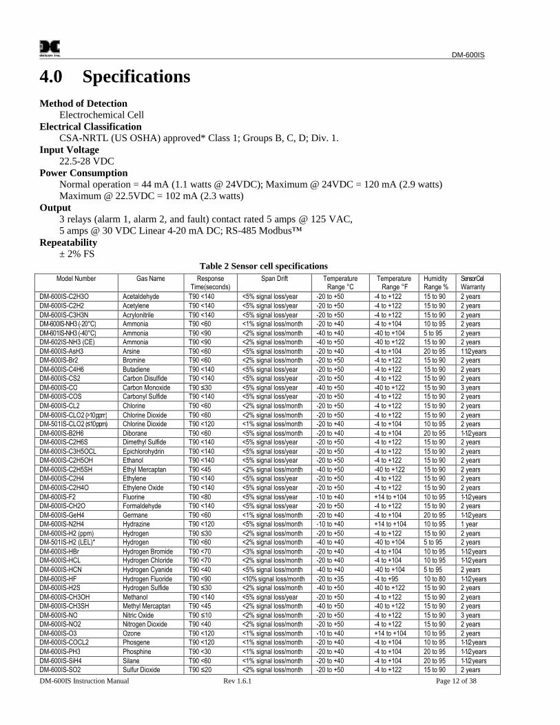
4.0 Specifications
Method of DetectionElectrochemical Cell
Electrical ClassificationCSA-NRTL (US OSHA) approved* Class 1; Groups B, C, D; Div. 1.
Input Voltage22.5-28 VDC
Power ConsumptionNormal operation = 44 mA (1.1 watts @ 24VDC); Maximum @ 24VDC = 120 mA (2.9 watts)Maximum @ 22.5VDC = 102 mA (2.3 watts)
Output3 relays (alarm 1, alarm 2, and fault) contact rated 5 amps @ 125 VAC,5 amps @ 30 VDC Linear 4-20 mA DC; RS-485 Modbus™
Repeatability± 2% FS
Table 2 Sensor cell specifications
Model Number Gas Name ResponseTime(seconds)
Span Drift TemperatureRange °C
TemperatureRange °F
HumidityRange %
SensorCellWarranty
DM-600IS-C2H3O Acetaldehyde T90 <140 <5% signal loss/year -20 to +50 -4 to +122 15 to 90 2 years
DM-600IS-C2H2 Acetylene T90 <140 <5% signal loss/year -20 to +50 -4 to +122 15 to 90 2 years
DM-600IS-C3H3N Acrylonitrile T90 <140 <5% signal loss/year -20 to +50 -4 to +122 15 to 90 2 yearsDM-600IS-NH3 (-20°C) Ammonia T90 <60 <1% signal loss/month -20 to +40 -4 to +104 10 to 95 2 years
DM-601IS-NH3 (-40°C) Ammonia T90 <90 <2% signal loss/month -40 to +40 -40 to +104 5 to 95 2 yearsDM-602IS-NH3 (CE) Ammonia T90 <90 <2% signal loss/month -40 to +50 -40 to +122 15 to 90 2 years
DM-600IS-AsH3 Arsine T90 <60 <5% signal loss/month -20 to +40 -4 to +104 20 to 95 11/2yearsDM-600IS-Br2 Bromine T90 <60 <2% signal loss/month -20 to +50 -4 to +122 15 to 90 2 years
DM-600IS-C4H6 Butadiene T90 <140 <5% signal loss/year -20 to +50 -4 to +122 15 to 90 2 yearsDM-600IS-CS2 Carbon Disulfide T90 <140 <5% signal loss/year -20 to +50 -4 to +122 15 to 90 2 years
DM-600IS-CO Carbon Monoxide T90 ≤30 <5% signal loss/year -40 to +50 -40 to +122 15 to 90 3 yearsDM-600IS-COS Carbonyl Sulfide T90 <140 <5% signal loss/year -20 to +50 -4 to +122 15 to 90 2 years
DM-600IS-CL2 Chlorine T90 <60 <2% signal loss/month -20 to +50 -4 to +122 15 to 90 2 years
DM-600IS-CLO2 (>10ppm) Chlorine Dioxide T90 <60 <2% signal loss/month -20 to +50 -4 to +122 15 to 90 2 yearsDM-501IS-CLO2 (≤10ppm) Chlorine Dioxide T90 <120 <1% signal loss/month -20 to +40 -4 to +104 10 to 95 2 years
DM-600IS-B2H6 Diborane T90 <60 <5% signal loss/month -20 to +40 -4 to +104 20 to 95 1-1/2yearsDM-600IS-C2H6S Dimethyl Sulfide T90 <140 <5% signal loss/year -20 to +50 -4 to +122 15 to 90 2 years
DM-600IS-C3H5OCL Epichlorohydrin T90 <140 <5% signal loss/year -20 to +50 -4 to +122 15 to 90 2 yearsDM-600IS-C2H5OH Ethanol T90 <140 <5% signal loss/year -20 to +50 -4 to +122 15 to 90 2 years
DM-600IS-C2H5SH Ethyl Mercaptan T90 <45 <2% signal loss/month -40 to +50 -40 to +122 15 to 90 2 yearsDM-600IS-C2H4 Ethylene T90 <140 <5% signal loss/year -20 to +50 -4 to +122 15 to 90 2 years
DM-600IS-C2H4O Ethylene Oxide T90 <140 <5% signal loss/year -20 to +50 -4 to +122 15 to 90 2 years
DM-600IS-F2 Fluorine T90 <80 <5% signal loss/year -10 to +40 +14 to +104 10 to 95 1-1/2yearsDM-600IS-CH2O Formaldehyde T90 <140 <5% signal loss/year -20 to +50 -4 to +122 15 to 90 2 years
DM-600IS-GeH4 Germane T90 <60 <1% signal loss/month -20 to +40 -4 to +104 20 to 95 1-1/2yearsDM-600IS-N2H4 Hydrazine T90 <120 <5% signal loss/month -10 to +40 +14 to +104 10 to 95 1 year
DM-600IS-H2 (ppm) Hydrogen T90 ≤30 <2% signal loss/month -20 to +50 -4 to +122 15 to 90 2 yearsDM-501IS-H2 (LEL)* Hydrogen T90 <60 <2% signal loss/month -40 to +40 -40 to +104 5 to 95 2 years
DM-600IS-HBr Hydrogen Bromide T90 <70 <3% signal loss/month -20 to +40 -4 to +104 10 to 95 1-1/2yearsDM-600IS-HCL Hydrogen Chloride T90 <70 <2% signal loss/month -20 to +40 -4 to +104 10 to 95 1-1/2years
DM-600IS-HCN Hydrogen Cyanide T90 <40 <5% signal loss/month -40 to +40 -40 to +104 5 to 95 2 years
DM-600IS-HF Hydrogen Fluoride T90 <90 <10% signal loss/month -20 to +35 -4 to +95 10 to 80 1-1/2yearsDM-600IS-H2S Hydrogen Sulfide T90 ≤30 <2% signal loss/month -40 to +50 -40 to +122 15 to 90 2 years
DM-600IS-CH3OH Methanol T90 <140 <5% signal loss/year -20 to +50 -4 to +122 15 to 90 2 yearsDM-600IS-CH3SH Methyl Mercaptan T90 <45 <2% signal loss/month -40 to +50 -40 to +122 15 to 90 2 years
DM-600IS-NO Nitric Oxide T90 ≤10 <2% signal loss/month -20 to +50 -4 to +122 15 to 90 3 yearsDM-600IS-NO2 Nitrogen Dioxide T90 <40 <2% signal loss/month -20 to +50 -4 to +122 15 to 90 2 years
DM-600IS-O3 Ozone T90 <120 <1% signal loss/month -10 to +40 +14 to +104 10 to 95 2 yearsDM-600IS-COCL2 Phosgene T90 <120 <1% signal loss/month -20 to +40 -4 to +104 10 to 95 1-1/2years
DM-600IS-PH3 Phosphine T90 <30 <1% signal loss/month -20 to +40 -4 to +104 20 to 95 1-1/2years
DM-600IS-SiH4 Silane T90 <60 <1% signal loss/month -20 to +40 -4 to +104 20 to 95 1-1/2yearsDM-600IS-SO2 Sulfur Dioxide T90 ≤20 <2% signal loss/month -20 to +50 -4 to +122 15 to 90 2 years
DM-600IS
DM-600IS Instruction Manual Rev 1.6.1 Page 13 of 38
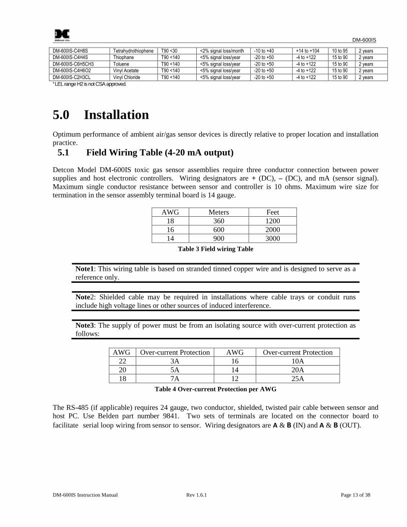
DM-600IS-C4H8S Tetrahydrothiophene T90 <30 <2% signal loss/month -10 to +40 +14 to +104 10 to 95 2 yearsDM-600IS-C4H4S Thiophane T90 <140 <5% signal loss/year -20 to +50 -4 to +122 15 to 90 2 years
DM-600IS-C6H5CH3 Toluene T90 <140 <5% signal loss/year -20 to +50 -4 to +122 15 to 90 2 yearsDM-600IS-C4H6O2 Vinyl Acetate T90 <140 <5% signal loss/year -20 to +50 -4 to +122 15 to 90 2 years
DM-600IS-C2H3CL Vinyl Chloride T90 <140 <5% signal loss/year -20 to +50 -4 to +122 15 to 90 2 years
*LELrangeH2 isnotCSAapproved.
5.0 Installation
Optimum performance of ambient air/gas sensor devices is directly relative to proper location and installationpractice.
5.1 Field Wiring Table (4-20 mA output)
Detcon Model DM-600IS toxic gas sensor assemblies require three conductor connection between powersupplies and host electronic controllers. Wiring designators are + (DC), – (DC), and mA (sensor signal).Maximum single conductor resistance between sensor and controller is 10 ohms. Maximum wire size fortermination in the sensor assembly terminal board is 14 gauge.
AWG Meters Feet18 360 120016 600 200014 900 3000
Table 3 Field wiring Table
Note1: This wiring table is based on stranded tinned copper wire and is designed to serve as areference only.
Note2: Shielded cable may be required in installations where cable trays or conduit runsinclude high voltage lines or other sources of induced interference.
Note3: The supply of power must be from an isolating source with over-current protection asfollows:
AWG Over-current Protection AWG Over-current Protection22 3A 16 10A20 5A 14 20A18 7A 12 25A
Table 4 Over-current Protection per AWG
The RS-485 (if applicable) requires 24 gauge, two conductor, shielded, twisted pair cable between sensor andhost PC. Use Belden part number 9841. Two sets of terminals are located on the connector board to
facilitate serial loop wiring from sensor to sensor. Wiring designators are A & B (IN) and A & B (OUT).
DM-600IS
DM-600IS Instruction Manual Rev 1.6.1 Page 14 of 38
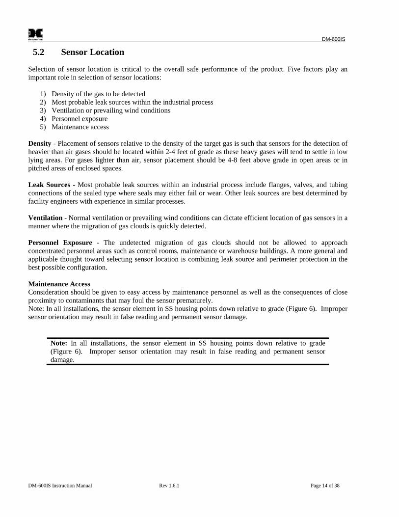
5.2 Sensor Location
Selection of sensor location is critical to the overall safe performance of the product. Five factors play animportant role in selection of sensor locations:
1) Density of the gas to be detected2) Most probable leak sources within the industrial process3) Ventilation or prevailing wind conditions4) Personnel exposure5) Maintenance access
Density - Placement of sensors relative to the density of the target gas is such that sensors for the detection ofheavier than air gases should be located within 2-4 feet of grade as these heavy gases will tend to settle in lowlying areas. For gases lighter than air, sensor placement should be 4-8 feet above grade in open areas or inpitched areas of enclosed spaces.
Leak Sources - Most probable leak sources within an industrial process include flanges, valves, and tubingconnections of the sealed type where seals may either fail or wear. Other leak sources are best determined byfacility engineers with experience in similar processes.
Ventilation - Normal ventilation or prevailing wind conditions can dictate efficient location of gas sensors in amanner where the migration of gas clouds is quickly detected.
Personnel Exposure - The undetected migration of gas clouds should not be allowed to approachconcentrated personnel areas such as control rooms, maintenance or warehouse buildings. A more general andapplicable thought toward selecting sensor location is combining leak source and perimeter protection in thebest possible configuration.
Maintenance AccessConsideration should be given to easy access by maintenance personnel as well as the consequences of closeproximity to contaminants that may foul the sensor prematurely.Note: In all installations, the sensor element in SS housing points down relative to grade (Figure 6). Impropersensor orientation may result in false reading and permanent sensor damage.
Note: In all installations, the sensor element in SS housing points down relative to grade(Figure 6). Improper sensor orientation may result in false reading and permanent sensordamage.
DM-600IS
DM-600IS Instruction Manual Rev 1.6.1 Page 15 of 38
Drain
Conduit
"T" EYS Seal Fitting
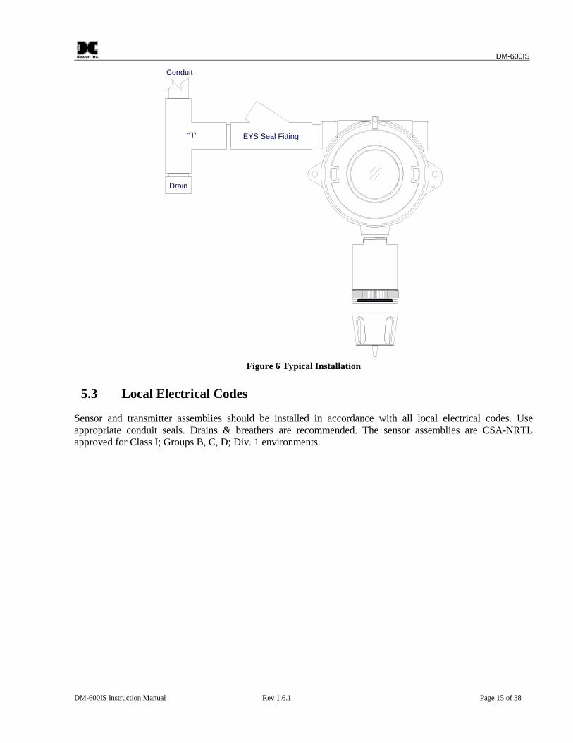
Figure 6 Typical Installation
5.3 Local Electrical Codes
Sensor and transmitter assemblies should be installed in accordance with all local electrical codes. Useappropriate conduit seals. Drains & breathers are recommended. The sensor assemblies are CSA-NRTLapproved for Class I; Groups B, C, D; Div. 1 environments.
DM-600IS
DM-600IS Instruction Manual Rev 1.6.1 Page 16 of 38
5.4 Installation Procedure
5.5"
6.1"
5.825"
4.65"
Wa
ll(o
roth
er
mou
ntin
gsu
rfa
ce
1/4" Mounting holes
8-32 tappedground point
3/4" NPT Ports
Intrinsically SafeSensor Head
8.985"
Cal Port
2"
0.5"
Splash Guard
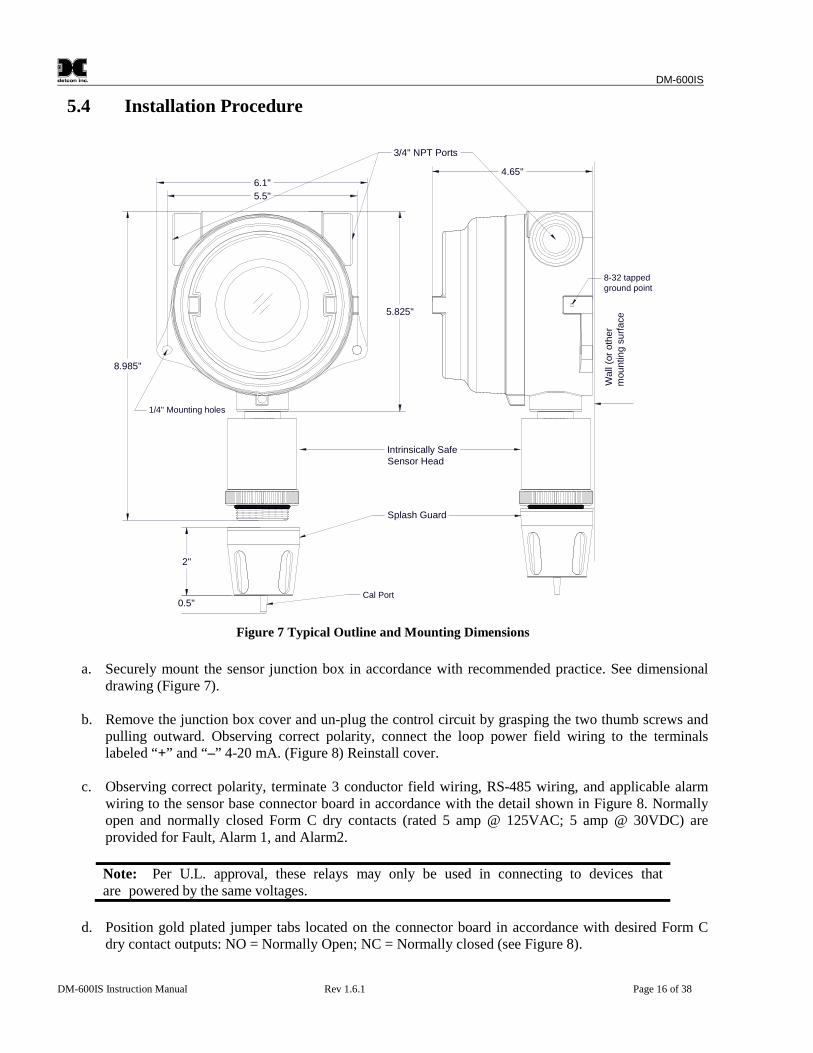
Figure 7 Typical Outline and Mounting Dimensions
a. Securely mount the sensor junction box in accordance with recommended practice. See dimensionaldrawing (Figure 7).
b. Remove the junction box cover and un-plug the control circuit by grasping the two thumb screws andpulling outward. Observing correct polarity, connect the loop power field wiring to the terminalslabeled “+” and “–” 4-20 mA. (Figure 8) Reinstall cover.
c. Observing correct polarity, terminate 3 conductor field wiring, RS-485 wiring, and applicable alarmwiring to the sensor base connector board in accordance with the detail shown in Figure 8. Normallyopen and normally closed Form C dry contacts (rated 5 amp @ 125VAC; 5 amp @ 30VDC) areprovided for Fault, Alarm 1, and Alarm2.
Note: Per U.L. approval, these relays may only be used in connecting to devices thatare powered by the same voltages.
d. Position gold plated jumper tabs located on the connector board in accordance with desired Form Cdry contact outputs: NO = Normally Open; NC = Normally closed (see Figure 8).
DM-600IS
DM-600IS Instruction Manual Rev 1.6.1 Page 17 of 38
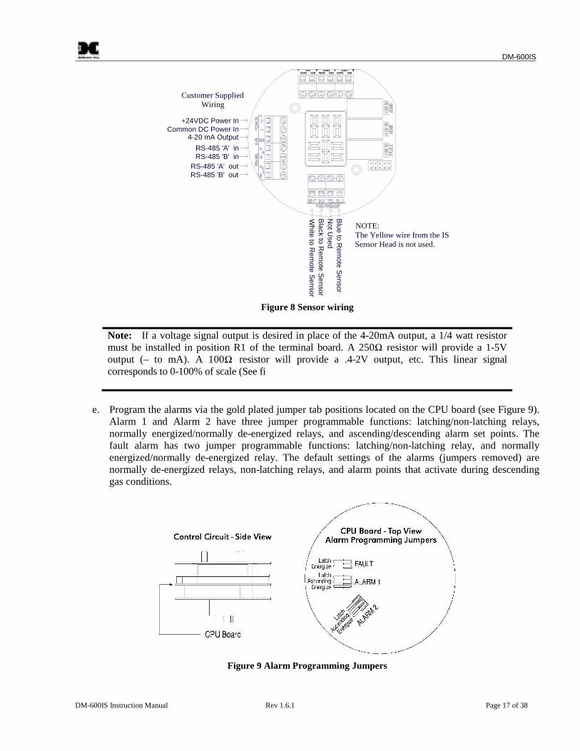
NOTE:The Yellow wire from the ISSensor Head is not used.
+24VDC Power InCommon DC Power In
4-20 mA Output
Wh
iteto
Re
mo
teS
en
sor
Bla
ck
toR
em
ote
Se
nso
r
Blu
eto
Re
mo
teS
en
sor
No
tU
sed
Customer SuppliedWiring
RS-485 'A' inRS-485 'B' in
RS-485 'A' outRS-485 'B' out
Figure 8 Sensor wiring
Note: If a voltage signal output is desired in place of the 4-20mA output, a 1/4 watt resistormust be installed in position R1 of the terminal board. A 250Ω resistor will provide a 1-5Voutput (– to mA). A 100Ω resistor will provide a .4-2V output, etc. This linear signalcorresponds to 0-100% of scale (See fi
e. Program the alarms via the gold plated jumper tab positions located on the CPU board (see Figure 9).Alarm 1 and Alarm 2 have three jumper programmable functions: latching/non-latching relays,normally energized/normally de-energized relays, and ascending/descending alarm set points. Thefault alarm has two jumper programmable functions: latching/non-latching relay, and normallyenergized/normally de-energized relay. The default settings of the alarms (jumpers removed) arenormally de-energized relays, non-latching relays, and alarm points that activate during descendinggas conditions.
Figure 9 Alarm Programming Jumpers
DM-600IS
DM-600IS Instruction Manual Rev 1.6.1 Page 18 of 38
If a jumper tab is installed in the latch position that alarm relay will be in the latching mode. Thelatching mode will latch the alarm after alarm conditions have cleared until the alarm reset function isactivated. The non-latching mode (jumper removed) will allow alarms to de-activate automatically oncealarm conditions have cleared.
If a jumper tab is installed in the energize position, that alarm relay will be in the energized mode. Theenergized mode will energize or activate the alarm relay when there is no alarm condition and de-energize or de-activate the alarm relay when there is an alarm condition. The de-energized mode(jumper removed) will energize or activate the alarm relay during an alarm condition and de-energize or de-activate the alarm relay when there is no alarm condition.
If a jumper tab is installed in the ascending position that alarm relay will be in the ascending mode. Theascending mode will cause an alarm to fire when the gas concentration detected is greater than or equal to thealarm set point. The descending mode (jumper removed) will cause an alarm to fire when the gasconcentration detected is lesser than or equal to the alarm set point. Except in special applications, toxic gasmonitoring will require alarms to fire in “ASCENDING” gas conditions.
Any unused jumper tabs should be stored on the connector board on the terminal strip labeled “UnusedJumpers” (see Figure 8).
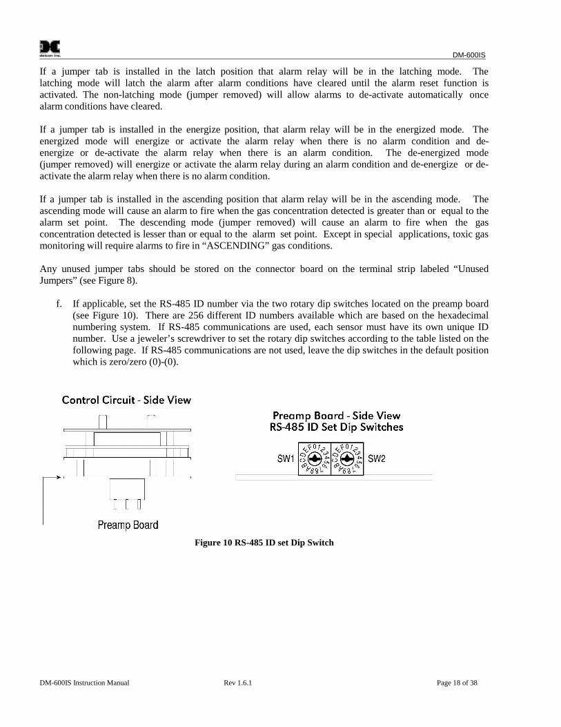
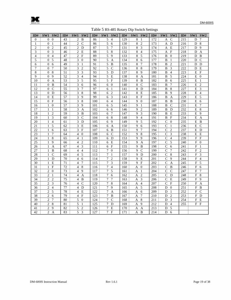
f. If applicable, set the RS-485 ID number via the two rotary dip switches located on the preamp board(see Figure 10). There are 256 different ID numbers available which are based on the hexadecimalnumbering system. If RS-485 communications are used, each sensor must have its own unique IDnumber. Use a jeweler’s screwdriver to set the rotary dip switches according to the table listed on thefollowing page. If RS-485 communications are not used, leave the dip switches in the default positionwhich is zero/zero (0)-(0).
Figure 10 RS-485 ID set Dip Switch
DM-600IS
DM-600IS Instruction Manual Rev 1.6.1 Page 19 of 38
Table 5 RS-485 Rotary Dip Switch Settings
ID# SW1 SW2 ID# SW1 SW2 ID# SW1 SW2 ID# SW1 SW2 ID# SW1 SW2 ID# SW1 SW20 0 0 43 2 B 86 5 4 129 8 1 172 A C 215 D 71 0 1 44 2 C 86 5 6 130 8 2 173 A D 216 D 82 0 2 45 2 D 87 5 7 131 8 3 174 A E 217 D 93 0 3 46 2 E 88 5 8 132 8 4 175 A F 218 D A4 0 4 47 2 F 89 5 9 133 8 5 176 B 0 219 D B5 0 5 48 3 0 90 5 A 134 8 6 177 B 1 220 D C6 0 6 49 3 1 91 5 B 135 8 7 178 B 2 221 D D7 0 7 50 3 2 92 5 C 136 8 8 179 B 3 222 D E8 0 8 51 3 3 93 5 D 137 8 9 180 B 4 223 E F9 0 9 52 3 4 94 5 E 138 8 A 181 B 5 224 E 010 0 A 53 3 5 95 5 F 139 8 B 182 B 6 225 E 111 0 B 54 3 6 96 6 0 140 8 C 183 B 7 226 E 212 0 C 55 3 7 97 6 1 141 8 D 184 B 8 227 E 313 0 D 56 3 8 98 6 2 142 8 E 185 B 9 228 E 414 0 E 57 3 9 99 6 3 143 8 F 186 B A 229 E 515 0 F 56 3 8 100 6 4 144 9 0 187 B B 230 E 616 1 0 57 3 9 101 6 5 145 9 1 188 B C 231 E 717 1 1 58 3 A 102 6 6 146 9 2 189 B D 232 E 818 1 2 59 3 B 103 6 7 147 9 3 190 B E 233 E 919 1 3 60 3 C 104 6 8 148 9 4 191 B F 234 E A20 1 4 61 3 D 105 6 9 149 9 5 192 C 0 235 E B21 1 5 62 3 E 106 6 A 150 9 6 193 C 1 236 E C22 1 6 63 3 F 107 6 B 151 9 7 194 C 2 237 E D23 1 7 64 4 0 108 6 C 152 9 8 195 C 3 238 E E24 1 8 65 4 1 109 6 D 153 9 9 196 C 4 239 F F25 1 9 66 4 2 110 6 E 154 9 A 197 C 5 240 F 026 1 A 67 4 3 111 6 F 155 9 B 198 C 6 241 F 127 1 B 68 4 4 112 7 0 156 9 C 199 C 7 242 F 228 1 C 69 4 5 113 7 1 157 9 D 200 C 8 243 F 329 1 D 70 4 6 114 7 2 158 9 E 201 C 9 244 F 430 1 E 71 4 7 115 7 3 159 9 F 202 C A 245 F 531 1 F 72 4 8 116 7 4 160 A 0 203 C B 246 F 632 2 0 73 4 9 117 7 5 161 A 1 204 C C 247 F 733 2 1 74 4 A 118 7 6 162 A 2 205 C D 248 F 834 2 2 75 4 B 119 7 7 163 A 3 206 C E 249 F 935 2 3 76 4 C 120 7 8 164 A 4 207 C F 250 F A36 2 4 77 4 D 121 7 9 165 A 5 208 D 0 251 F B37 2 5 78 4 E 122 7 A 166 A 6 209 D 1 252 F C38 2 6 79 4 F 123 7 B 167 A 7 210 D 2 253 F D39 2 7 80 5 0 124 7 C 168 A 8 211 D 3 254 F E40 2 8 81 5 1 125 7 D 169 A 9 212 D 4 255 F F41 2 9 82 5 2 126 7 E 170 A A 213 D 542 2 A 83 5 3 127 7 F 171 A B 214 D 6
DM-600IS
DM-600IS Instruction Manual Rev 1.6.1 Page 20 of 38
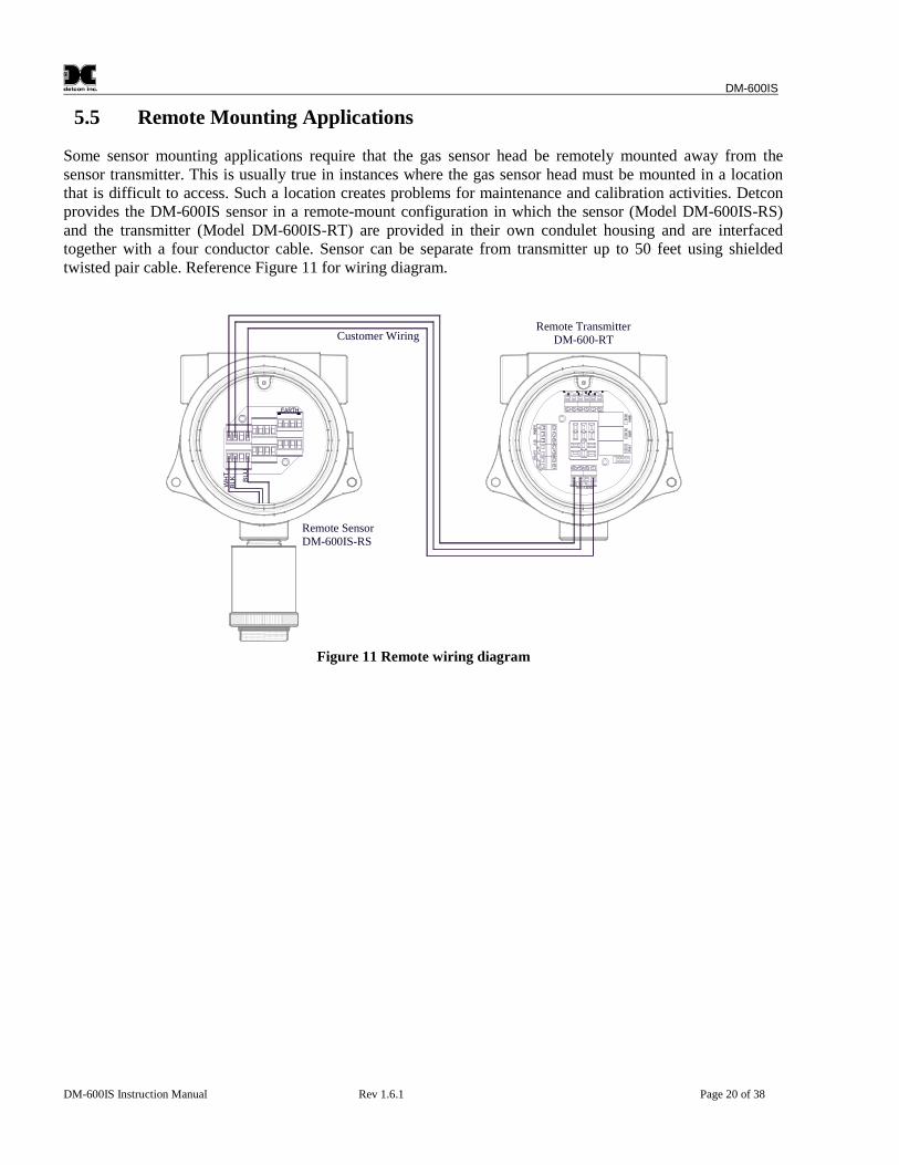
5.5 Remote Mounting Applications
Some sensor mounting applications require that the gas sensor head be remotely mounted away from thesensor transmitter. This is usually true in instances where the gas sensor head must be mounted in a locationthat is difficult to access. Such a location creates problems for maintenance and calibration activities. Detconprovides the DM-600IS sensor in a remote-mount configuration in which the sensor (Model DM-600IS-RS)and the transmitter (Model DM-600IS-RT) are provided in their own condulet housing and are interfacedtogether with a four conductor cable. Sensor can be separate from transmitter up to 50 feet using shieldedtwisted pair cable. Reference Figure 11 for wiring diagram.
Remote SensorDM-600IS-RS
Remote TransmitterDM-600-RT
WH
TB
LK BLU
Customer Wiring
Figure 11 Remote wiring diagram
DM-600IS
DM-600IS Instruction Manual Rev 1.6.1 Page 21 of 38
6.0 Startup
Upon completion of all mechanical mounting and termination of all field wiring, apply system power andobserve the following normal conditions:
a. DM-6xxIS “Fault” LED is off.
b. A temporary upscale reading will occur as the sensor powers up. This upscale reading will clear to “0”ppm within approximately 30 minutes of turn-on, assuming there is no gas in the area of the sensor.
NOTE 1: If the display contrast needs adjustment, refer to section 15.0.
NOTE 2: Zero Clearing with Biased CellsSome electrochemical sensors are biased with an excitation voltage. When power to the sensoris lost, this bias voltage slowly decays. When power is restored after long periods (multiplehours) of being unpowered, a surge in sensor output takes place and a long and slow re-establishing of the sensor’s zero baseline takes place. This re-stabilization time may range from1 hour to 24 hours depending on the type of sensor and range of operation. The sensor typesthat this applies to are the following: HCl, NO, plus all the VOC sensors, C2H30, C2H2,C3H3N, C4H6, CS2, COS, C2H6S, C3H5OCL, C2H5OH, C2H4, C2H4O, CH2O, CH3OH,C4H4S, C4H6O2, C6H5CH3 and C2H3CL.
If this characteristic is problematic for your specific application, a battery backup or uninterruptible powersupply is recommended.
NOTE 3: All alarms will be disabled for 1 minute after power up. In the event of powerfailure, the alarm disable periods will begin again once power has been restored. If using abiased cell (see note 2 above), this 1 minute delay may likely be inadequate for the signal toclear below alarm levels so manually disabling alarms is advised.
6.1 Initial Operational Tests
After a warm up period has been allowed for, the sensor should be checked to verify sensitivity to its targetgas.
Material Requirements Detcon PN 943-000006-132 Calibration Adapter Span gas containing the target gas in air or nitrogen. It is recommended that the target gas
concentration be 50% of scale at a controlled flow rate of 500 ml/min. For example, a Model DM-600IS-H2S sensor in the range 0-100ppm would require a test gas of 50ppm H2S. For a sensor with arange of 0-10ppm a test gas of 5ppm is recommended, etc.
a. Attach the calibration adapter to the sensor housing. Apply the test gas at a controlled flow rate of 500ml/m. Observe that the LCD display increases to a level of 20% of range or higher.
b. Remove the test gas and observe that the LCD display decreases to “0 PPM”.
c. If alarms are activated during the test and have been programmed for latching operation, reset themaccording to the instructions in section 11.2
DM-600IS
DM-600IS Instruction Manual Rev 1.6.1 Page 22 of 38
Initial operational tests are complete. Detcon toxic gas sensors are pre-calibrated prior to shipment and will, inmost cases, not require significant adjustment on start up. However, it is recommended that a completecalibration test and adjustment be performed within 24 hours of installation. Refer to calibration instructions inSection 9.0.
7.0 Operating Software & Magnetic Interface
Operating software is menu listed with operator interface via the two magnetic program switches located underthe face plate. The two switches are referred to as “PGM 1” and “PGM 2”. The menu list consists of 3 itemswhich include submenus as indicated below. (Note: see section 8.0 for a complete software flow chart.)
1. Normal Operationa) Current Status
2. Calibration Modea) Zerob) Span
3. Program Menua) View Program Statusb) Alarm 1 Levelc) Alarm 2 Leveld) Set Calibration Level
7.1 Normal Operation
In normal operation, the display tracks the current status of the sensor and gas concentration and appears as:“0 PPM xxx” (the “xxx” is the abbreviated gas type, i.e. “0 PPM H2S”). The mA current output correspondsto the monitoring level of 0-100% of range = 4-20 mA.
7.2 Calibration Mode
Calibration mode allows for sensor zero and span adjustments. “1-ZERO 2-SPAN”
7.2.1 Zero AdjustmentZero is set in ambient air with no target gas present or with zero gas applied to the sensor. “AUTO ZERO”
7.2.2 Span AdjustmentSpan adjustment is performed with a target gas concentration of 50% of range in air or nitrogen. Span gasconcentrations other than 50% of range may be used. Refer to section 7.3.4 for details. “AUTO SPAN”
7.3 Program Mode
The program mode provides a program status menu (View Program Status) to check operational parameters. Italso allows for the adjustment of the calibration gas level setting.
7.3.1 Program StatusThe program status scrolls through a menu that displays:
DM-600IS
DM-600IS Instruction Manual Rev 1.6.1 Page 23 of 38
The software version number. Range is ### The alarm set point level of alarm 1. The menu item appears as: “ALM1 SET @ ##PPM” The alarm firing direction of alarm 1. The menu item appears as: “ALM1 ASCENDING” or
descending. The alarm relay latch mode of alarm 1. The menu item appears as: “ALM1 NONLATCHING” or latching. The alarm relay energize state of alarm 1. The menu item appears as: “ALM1 DE-ENERGIZED” or energized. The alarm set point level of alarm 2. The menu item appears as: “ALM2 SET @ ##PPM” The alarm firing direction of alarm 2. The menu item appears as: “ALM2 ASCENDING” or
descending. The alarm relay latch mode of alarm 2. The menu item appears as: “ALM2 LATCHING” or non- latching. The alarm relay energize state of alarm 2. The menu item appears as: “ALM2 DE-ENERGIZED” or energized. The alarm relay latch mode of the fault alarm. The menu item appears as: “FLT NONLATCHING” or latching. The alarm relay energize state of the fault alarm. The menu item appears as: “FLT ENERGIZED” or de-
energized. The calibration gas level setting. The menu item appears as: “CalLevel @ xxPPM” Identification of the RS-485 ID number setting. The menu item appears as: “485 ID SET @ ##” The estimated remaining sensor life. The menu item appears as: “SENSOR LIFE 100%”
7.3.2 Alarm 1 Level AdjustmentThe alarm 1 level is adjustable from 10% to 90% of range. The menu item appears as: “SET ALM1 @##PPM”
7.3.3 Alarm 2 Level AdjustmentThe alarm 2 level is adjustable from 10% to 90% of range. The menu item appears as: “SET ALM2 @##PPM”
7.3.4 Calibration Level AdjustmentThe calibration level is adjustable from 10% to 90% of range. The menu item appears as: “CalLevel @##PPM”
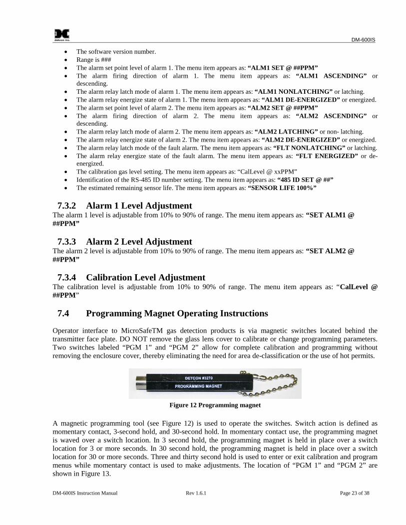
7.4 Programming Magnet Operating Instructions
Operator interface to MicroSafeTM gas detection products is via magnetic switches located behind thetransmitter face plate. DO NOT remove the glass lens cover to calibrate or change programming parameters.Two switches labeled “PGM 1” and “PGM 2” allow for complete calibration and programming withoutremoving the enclosure cover, thereby eliminating the need for area de-classification or the use of hot permits.
Figure 12 Programming magnet
A magnetic programming tool (see Figure 12) is used to operate the switches. Switch action is defined asmomentary contact, 3-second hold, and 30-second hold. In momentary contact use, the programming magnetis waved over a switch location. In 3 second hold, the programming magnet is held in place over a switchlocation for 3 or more seconds. In 30 second hold, the programming magnet is held in place over a switchlocation for 30 or more seconds. Three and thirty second hold is used to enter or exit calibration and programmenus while momentary contact is used to make adjustments. The location of “PGM 1” and “PGM 2” areshown in Figure 13.
DM-600IS
DM-600IS Instruction Manual Rev 1.6.1 Page 24 of 38
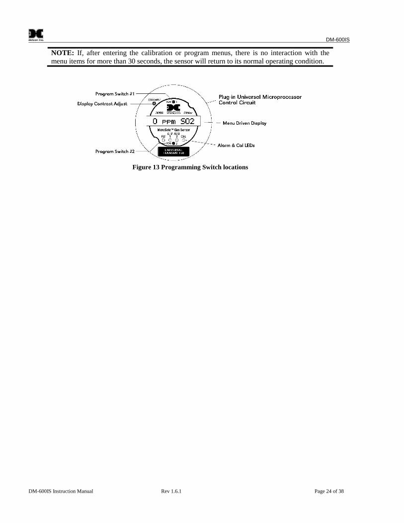
NOTE: If, after entering the calibration or program menus, there is no interaction with themenu items for more than 30 seconds, the sensor will return to its normal operating condition.
Figure 13 Programming Switch locations
DM-600IS
DM-600IS Instruction Manual Rev 1.6.1 Page 25 of 38
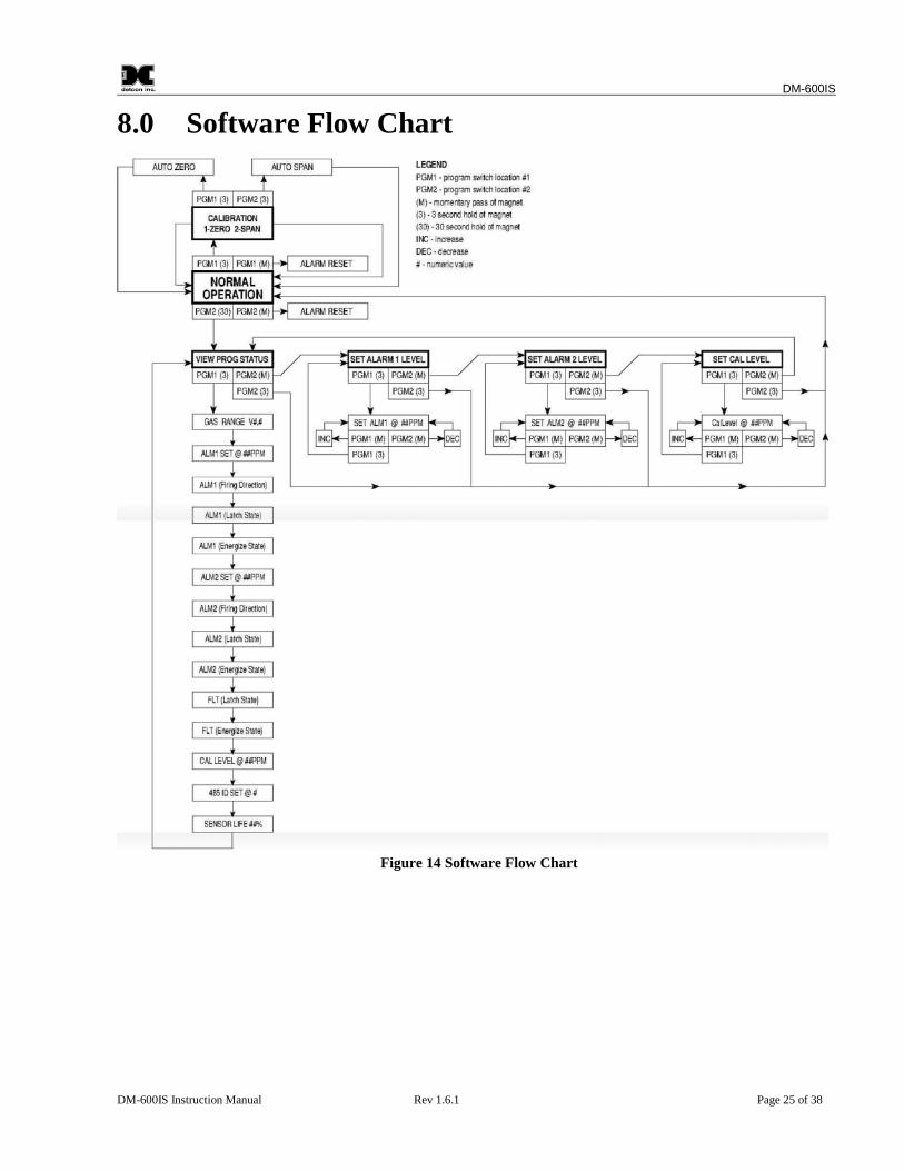
8.0 Software Flow Chart
Figure 14 Software Flow Chart
DM-600IS
DM-600IS Instruction Manual Rev 1.6.1 Page 26 of 38
9.0 Calibration
Material Requirements
Detcon PN 327-000000-000 MicroSafeTM Programming Magnet Detcon PN 943-000006-132 Calibration Adapter Span gas containing the target gas in air or nitrogen. The target gas concentration is recommended at
50% of range (which is the factory default) at a controlled flow rate of 500 ml/min. Example: for aModel DM-600IS-H2S sensor with a range of 0-100ppm, a test gas of 50 ppm is recommended. For asensor with a range of 0-10 ppm a test gas of 5 ppm is recommended, etc. Other concentrations can beused as long as they fall within 10% to 90% of range. See section 9.2 for details. Reference section 10-2) -b) if you do not know the sensor target gas or range of detection.
9.1 Calibration Procedure – Zero
NOTE: Before performing a zero calibration, be sure there is no background gas present orapply a zero gas standard prior to performing zero calibration.
a. Enter the calibration menu by holding the programming magnet stationary over “PGM 1” (see Figure13) for 3 seconds until the display reads “1-ZERO 2-SPAN” then withdraw the magnet. Note that the“CAL” LED is on.
b. Next, enter the zero menu by holding the magnet stationary over “PGM 1” for 3 seconds until thedisplay reads: “SETTING ZERO”, then withdraw the magnet. The sensor has now entered the autozero mode. When it is complete the display will read “ZERO COMPLETE” for 5 seconds and thenreturn to the normal operations menu reading “(0 PPM)”.
Zero calibration is complete.
9.2 Calibration Procedure – Span
CAUTION: Verification of the correct calibration gas level setting and calibration span gasconcentration is required before “span” calibration. These two numbers must be equal.
Calibration consists of entering the calibration function and following the menu-displayed instructions. Thedisplay will ask for the application of span gas in a specific concentration. This concentration must be equal tothe calibration gas level setting. The factory default setting for span gas concentration is 50% of range. In thisinstance, a span gas containing a concentration equal to 50% of range is required. If a span gas containing 50%of range is not available, other concentrations may be used as long as they fall within 10% to 90% of range.However, any alternate span gas concentration value must be programmed via the calibration gas level menubefore proceeding with span calibration. Follow the instructions below for span calibration.
a. Verify the current calibration gas level setting as indicated by the programming status menu. To dothis, follow the instructions in section Error! Reference source not found. and make note of thesetting found in section 10- Error! Reference source not found.. The item appears as “GasLevel @xxPPM”.
DM-600IS
DM-600IS Instruction Manual Rev 1.6.1 Page 27 of 38
b. If the calibration gas level setting is equal to your calibration span gas concentration, proceed to item“f”. If not, adjust the calibration gas level setting so that it is equal to your calibration span gasconcentration, as instructed in items “c” through “e”.
c. Enter the programming menu by holding the programming magnet stationary over “PGM 2” for 30seconds until the display reads “VIEW PROG STATUS” then withdraw the magnet. At this pointyou can scroll through the programming menu by momentarily waving the programming magnet over“PGM 1” or “PGM 2”. The menu options are: View Program Status, and Set Cal Level.
d. From the programming menu scroll to the calibration level listing. The menu item appears as: “SETCAL LEVEL”. Enter the menu by holding the programming magnet stationary over “PGM 1” for 3seconds until the display reads “CalGas @ ##PPM”, then withdraw the magnet. Use theprogramming magnet to make an adjustment to “PGM 1” to increase or “PGM 2” to decrease thedisplay reading until the reading is equal to the desired calibration span gas concentration. Exit to theprogramming menu by holding the programming magnet over “PGM1” for 3 seconds.
e. Exit back to normal operation by holding the programming magnet over “PGM 2” for 3 seconds, orautomatically return to normal operation in 30 seconds.
f. From the calibration menu “1-ZERO 2-SPAN” (section 9.1a) proceed into the span adjust function byholding the programming magnet stationary over “PGM 2” for 3 seconds then withdraw theprogramming magnet. At this point the display will ask for the application of the target gas andconcentration. The display reads “APPLY xxPPM xxx” The x’s here will indicate the actualconcentration requested.
g. Apply the calibration test gas at a flow rate of 500 milliliters per minute. As the sensor signal changes,the display will change to “AutoSpan xxPPM”. The “xx” part of the reading indicates the actual gasreading which will increase until the sensor stabilizes. When the sensor signal is stable it will autospan to the correct ppm reading and the display will change to “SPAN COMPLETE” for 3 seconds,then to “SENSOR LIFE: xxx%” and then “REMOVE GAS”. Remove the gas. When the signallevel has fallen below 10% of full scale, the display will return to the normal operating mode.
NOTE 1: If there is not a minimal response to the cal gas in the first minute, the sensorwill enter into the calibration fault mode which will cause the display to alternate betweenthe sensor’s current status reading and the calibration fault screen which appears as:“SPAN FAULT #1” (see section 9.3)
NOTE 2: If during the auto-span function the sensor fails to meet a minimum signalstability criteria, the sensor will enter the calibration fault mode which will cause thedisplay to alternate between the sensor’s current status reading and the calibration faultscreen which appears as: “SPAN FAULT #2” (see section 9.3).
9.3 Additional Notes
1. Upon entering the calibration menu, the 4-20 mA signal drops to 2 mA and is held at this level untilyou return to normal operation.
2. If during calibration the sensor circuitry is unable to attain the proper adjustment for zero or span, thesensor will enter into the calibration fault mode which will activate the fault LED (see section Error!Reference source not found.) and will cause the display to alternate between the sensor’s currentstatus reading and the calibration fault description. In these cases, the previous calibration points will

DM-600IS
DM-600IS Instruction Manual Rev 1.6.1 Page 28 of 38
remain in memory. If this occurs you may attempt to recalibrate by entering the calibration menu asdescribed in section 9.1-a. If the sensor fails again, defer to technical trouble shooting (see section16.0).
9.4 Calibration Frequency
In most applications, monthly to quarterly calibration intervals will assure reliable detection. However,industrial environments differ. Upon initial installation and commissioning, close frequency tests should beperformed, weekly to monthly. Test results should be recorded and reviewed to determine a suitablecalibration interval.
10.0 Status of Programming, Version, Alarms,Calibration Level, RS-485, and Sensor Life
The programming menu has a “View Program Status” listing that allows the operator to view the gas, range,and software version number of the program, as well as the calibration gas level setting, and estimatedremaining sensor life. The programming menu also allows the changing of the calibration gas level setting (seesection 9.2).
The following procedure is used to view the programming status of the sensor:
1) First, enter the programming menu by holding the programming magnet stationary over “PGM 2” for 30seconds until the display reads “VIEW PROG STATUS”, then withdraw the magnet. At this point youcan scroll through the programming menu by momentarily waving the programming magnet over “PGM1” or “PGM 2”. The menu options are: View Program Status, Set Alarm 1 Level, Set Alarm 2 Level, andSet Cal Level.
2) Next, scroll to the “VIEW PROG STATUS” listing and then hold the programming magnet over “PGM1” for 3 seconds. The menu will then automatically scroll, at five second intervals, through the followinginformation before returning back to the “VIEW PROG STATUS” listing.
a) The software version number.b) Range is ###.c) The alarm set point level of alarm 1. The menu item appears as: “ALM1 SET @ ##PPM”d) The alarm firing direction of alarm 1. The menu item appears as: “ALM1 ASCENDING” or
descending.e) The alarm relay latch mode of alarm 1. The menu item appears as: “ALM1 NONLATCHING” or latching.f) The alarm relay energize state of alarm 1. The menu item appears as: “ALM1 DE-ENERGIZED” or energized.g) The alarm set point level of alarm 2. The menu item appears as: “ALM2 SET @ ##PPM”h) The alarm firing direction of alarm 2. The menu item appears as: “ALM2 ASCENDING” or
descending.i) The alarm relay latch mode of alarm 2. The menu item appears as: “ALM2 LATCHING” or non- latching.j) The alarm relay energize state of alarm 2. The menu item appears as: “ALM2 DE-ENERGIZED” or energized.k) The alarm relay latch mode of the fault alarm. The menu item appears as: “FLT NONLATCHING” or latching.l) The alarm relay energize state of the fault alarm. The menu item appears as: “FLT ENERGIZED” or de-
energized.m) The calibration gas level setting. The menu item appears as: “CalLevel @ xxPPM”n) Identification of the RS-485 ID number setting. The menu item appears as: “485 ID SET @ ##”o) The estimated remaining sensor life. The menu item appears as: “SENSOR LIFE 100%”
3) Exit back to normal operations by holding the programming magnet over “PGM 2” for 3 seconds, orautomatically return to normal operation in 30 seconds.
DM-600IS
DM-600IS Instruction Manual Rev 1.6.1 Page 29 of 38
11.0 Programming Alarms
11.1 Alarm Levels
Both alarm 1 and alarm 2 levels are factory set prior to shipment. Alarm 1 is set at 20% of range and alarm 2 at40% of range. Both alarms can be set in 1% increments from 10% to 90% of range. The following procedure isused to change alarm set points:
a. First, enter the programming menu by holding the programming magnet stationary over “PGM 2” for30 seconds until the display reads “VIEW PROG STATUS”, then withdraw the magnet. At this pointyou can scroll through the programming menu by momentarily waving the programming magnet over“PGM 1” or “PGM 2”. The menu options are: View Program Status, Set Alarm 1 Level, Set Alarm 2Level, and Set Cal Level.
b. ALARM 1 LEVEL From the programming menu scroll to the alarm 1 level listing. The menu itemappears as: “SET ALARM 1 LEVEL”. Enter the menu by holding the programming magnetstationary over “PGM 1” for 3 seconds until the display reads “SET ALM1 @ ##PPM”, thenwithdraw the magnet. Use the programming magnet to make an adjustment to “PGM 1” to increase or“PGM 2” to decrease the display reading until the reading is equal to the desired alarm set point. Exitto the programming menu by holding the programming magnet over “PGM1” for 3 seconds, orautomatically return to the programming menu in 30 seconds.
c. ALARM 2 LEVEL From the programming menu scroll to the alarm 2 level listing. The menu itemappears as: “SET ALARM 2 LEVEL”. Enter the menu by holding the programming magnetstationary over “PGM 1” for 3 seconds until the display reads “SET ALM2 @ ##PPM”, thenwithdraw the magnet. Use the programming magnet to make an adjustment to “PGM 1” to increase or“PGM 2” to decrease the display reading until the reading is equal to the desired alarm set point. Exitto the programming menu by holding the programming magnet over “PGM1” for 3 seconds, orautomatically return to the programming menu in 30 seconds.
d. Exit back to normal operations by holding the programming magnet over “PGM 2” for 3 seconds, orautomatically return to normal operation in 30 seconds.
11.2 Alarm Reset
An alarm condition will cause the applicable alarm to activate its corresponding relay and LED. If alarm 1,alarm 2, or fault alarms have been programmed for latching relays, an alarm reset function must be activated toreset the alarms after an alarm condition has cleared. To reset the alarms, simply wave the programmingmagnet over either “PGM 1” or “PGM 2”, momentarily, while in normal operations mode and note that thecorresponding alarm LED(s) turn off.
11.3 Other Alarm Functions
Alarms are factory programmed to be non-latching, de-energized; and to fire under ascending gas conditions.The fault alarm relay is programmed as normally energized which is useful for detecting a 24VDC powersource failure. All alarm functions are programmable via jumper tabs. Changing alarm functions requires thesensor housing to be opened, thus declassification of the area is required. See section 5.4 for details.
DM-600IS
DM-600IS Instruction Manual Rev 1.6.1 Page 30 of 38
12.0 Program Features
Detcon MicroSafeTM toxic gas sensors incorporate a comprehensive program to accommodate easy operatorinterface and fail-safe operation. Program features are detailed in this section. Each sensor is factory tested,programmed, and calibrated prior to shipment.
Over RangeWhen the sensor detects gas greater than 100% of range, it will cause the display to flash the highest readingof its range on and off.
Under Range Fault(s)If the sensor should drift below a zero baseline of -10% of range, the display will indicate a fault: “ZEROFAULT”. This is typically fixed by performing another zero cal. When the total negative zero drift exceedsthe acceptable threshold the display will indicate “SENSOR FAULT” and you will longer be able to zerocalibrate.
Span Fault #1If during span calibration the sensor circuitry is unable to attain a minimum defined response to span gas, thesensor will enter into the calibration fault mode and cause the display to alternate between the sensor’s currentstatus reading and the calibration fault screen which appears as: “SPAN FAULT #1”. The previous calibrationsettings will remain saved in memory. Previous span calibration is retained.
Span Fault #2If during the span routine, the sensor circuitry is unable to attain a minimum defined stabilization point, thesensor will enter into the calibration fault mode and cause the display to alternate between the sensor’s currentstatus reading and the calibration fault screen which appears as “SPAN FAULT #2”. Previous span calibrationis retained.
Memory FaultIf new data points cannot successfully be stored to memory the display will indicate: “MEMORY FAULT”.
Fail-Safe/Fault SupervisionDetcon MicroSafeTM sensors are programmed for fail-safe operation. All fault conditions will illuminate thefault LED, and cause the display to read its corresponding fault condition: “ZERO FAULT”, “SENSORFAULT”, “SPAN FAULT #1”, or “SPAN FAULT #2”. A “SENSOR FAULT” and “ZERO FAULT” willcause the mA output to drop to zero (0) mA.
Sensor LifeThe “Sensor Life” feature gauges the remaining sensor life based on signal output from the sensor cell. Whensensor life of 25% or less remains the sensor cell should be replaced within a reasonable maintenanceschedule.
DM-600IS
DM-600IS Instruction Manual Rev 1.6.1 Page 31 of 38
13.0 Universal Transmitter Feature (Re-Initialization)
The Model DM600IS uses a universal transmitter design that allows the transmitter to be set up for any targetgas and any toxic concentration range. The original transmitter set-up is done at Detcon Inc. as part of thesensor test and calibration procedure, but it may also be changed in the field if necessary. The UniversalTransmitter feature is a significant convenience to the user because it allows hardware flexibility andminimizes the spare parts requirements to handle unexpected transmitter failures of different gas/ranges. Itis however, absolutely critical that changes to gas/range set-up of the Universal Transmitter be consistentwith the gas type and range of the Intrinsically Safe Sensor Head that it is connected to.
NOTE: If the Universal Transmitter is changed for gas type and range, it must be consistentwith the Intrinsically Safe sensor head it is mated with.
If the Universal Transmitter needs to be changed for gas type and range follow this procedure. First, unplugthe transmitter temporarily and then plug it back in. While the message “Universal Transmitter” appears, takethe program magnet and swipe it over magnet PGM1. This will reveal the set-up options for gas range and gastype.
Swipe over PGM1to advance through the options for gas range which include: 1, 2, 3....10 ppm 10, 15,20...100 ppm100, 200, 300...1000 ppm1000, 2000, 3000 10,000 ppmWhen the correct range is displayed, hold magnet over PGM1 for 3 seconds to accept the selection.
Next is your selection for the gas type. In this set-up you will enter the alpha-numeric characters of the gastype. Reference the list on page 3 for correct symbols. There is space for the chemical formula up to sixcharacters. Use GM1 and PGM2 swipes to advance through the alphabet and numbers 0-9 selection (there is ablank space after 9). When the correct alphanumeric character is highlighted, hold the magnet over PGM1 for3 seconds to lock it in. This moves you to the next blank and the procedure is repeated until the chemicalformula is completed. After the 6th character is locked in the transmitter will proceed to normal operation.
NOTE 1: If the gas symbol has more than 6 characters, the symbol can be replaced by anabbreviated version of the target gas name such as TOL or TOLUEN for Toluene which hasthe symbol C6H5CH3. For Epichlorohydrin (symbol C3H5OCL) you can substitute the nameEPI or EPICHL etc.
NOTE 2: When the Universal Transmitter is re-initialized and a new gas and range is entered,all of the previous customer settings for alarm levels and span gas value are reset to theirdefault levels. These must be re-programmed back to the customer specific settings
DM-600IS
DM-600IS Instruction Manual Rev 1.6.1 Page 32 of 38
14.0 RS-485 Protocol
Detcon MicroSafe™ toxic gas sensors feature Modbus™ compatible communications protocol and areaddressable via rotary dip switches for multi-point communications. Other protocols are available. Contact theDetcon factory for specific protocol requirements. Communication is two wire, half duplex 485, 9600 baud, 8data bits, 1 stop bit, no parity, with the sensor set up as a slave device. A master controller up to 4000 feetaway can theoretically poll up to 256 different sensors. This number may not be realistic in harshenvironments where noise and/or wiring conditions would make it impractical to place so many devices on thesame pair of wires. If a multi-point system is being utilized, each sensor should be set for a different address.Typical address settings are: 01, 02, 03, 04, 05, 06, 07, 08, 09, 0A, 0B, 0C, 0D, 0E, 0F, 10, 11, etc.
In most instances, RS-485 ID numbers are factory set or set during installation before commissioning. Ifrequired, the RS-485 ID number can be set via rotary dip switches located on the preamp circuit board.However, any change to the RS-485 ID number would require the sensor housing to be opened, thusdeclassification of the area would be required. See section 5.4-f) for details on changing the RS-485 IDnumber.
The following section explains the details of the Modbus™ protocol that the MicroSafeTM sensor supports.
Code 03 - Read Holding Registers is the only code supported by the transmitter. Each transmitter contains 6holding registers which reflect its current status.
Register # High Byte Low Byte0000 Gas type Sensor Life
Gas type is one of the following:01=CO, 02=H2S, 03=SO2, 04=H2, 05=HCN, 06=CL2, 07=NO2, 08=NO, 09=HCL, 10=NH3, 11=LEL,12=O2
Sensor life is an estimated remaining use of the sensor head, between 0% and 100% Example: 85=85% sensorlife
Register # High Byte Low Byte40001 Detectable Range
i.e. 100 for 0-100 ppm, 50 for 0-50 ppm, etc.
Register # High Byte Low Byte40002 Current Gas Reading
The current gas reading as a whole number. If the reading is displayed as 23.5 on the display, this registerwould contain the number 235.
Register # High Byte Low Byte40003 Alarm 1 Set point
This is the trip point for the first alarm.
Register # High Byte Low Byte40004 Alarm 2 Set point
This is the trip point for the second alarm.
DM-600IS
DM-600IS Instruction Manual Rev 1.6.1 Page 33 of 38
Register # High Byte Low Byte40005 Status Bits Status Bits
High ByteBit 7 Not used, always 0Bit 6 Not used, always 0Bit 5 Not used, always 0Bit 4 Not used, always 0Bit 3 1-Unit is in calibration 0-Normal operationBit 2 1-Alarm 2 is ascending 0-Alarm 2 is descendingBit 1 1-Alarm 2 is normally energized 0-Alarm 2 is normally de-energizedBit 0 1-Alarm 2 is latching 0-Alarm 2 is non-latching
Low ByteBit 7 1-Alarm 2 Relay is energized 0-Alarm 2 Relay is not energizedBit 6 1-Alarm 1 is ascending 0-Alarm 1 is descendingBit 5 1-Alarm 1 is normally energized 0-Alarm 1 is normally de-energizedBit 4 1-Alarm 1 is latching 0-Alarm 1 is non-latchingBit 3 1-Alarm 1 Relay is energized 0-Alarm 1 Relay is not energizedBit 2 1-Fault is normally energized 0-Fault is normally de-energizedBit 1 1-Fault is latching 0-Fault is non-latchingBit 0 1-Fault Relay is energized 0-Fault Relay is not energized
The following is a typical Master Query for device # 8:Field Name HEX DEC RTUSlave Address 08 8 0000 1000Function 03 3 0000 0011Start Address Hi 00 0 0000 0000Start Address Lo 00 0 0000 0000No. of Registers Hi 00 0 0000 0000No. of Registers Lo 06 6 0000 0110CRC ## #### ####CRC ## #### ####
The following is a typical Slave Response from device # 8:
Field Name HEX DEC RTU
Slave Address 08 8 0000 1000Function 03 3 0000 0011Byte Count 0C 12 0000 1100Reg40000 Data Hi 02 2 0000 0010Reg40000 Data Lo 64 100 0110 0100Reg40001 Data Hi 00 0 0000 0000Reg40001 Data Lo 64 100 0110 0100Reg40002 Data Hi 00 0 0000 0000Reg40002 Data Lo 07 7 0000 0111Reg40003 Data Hi 00 0 0000 0000Reg40003 Data Lo 0A 10 0000 1010Reg40004 Data Hi 00 0 0000 0000Reg40004 Data Lo 14 20 0001 0100Reg40005 Data Hi 05 5 0000 0101
DM-600IS
DM-600IS Instruction Manual Rev 1.6.1 Page 34 of 38
Reg40005 Data Lo 50 80 0101 0000CRC ## #### ####CRC ## #### ####
Additional Notes:The calibration LED will light when the transmitter is sending a response to a Master Query. Communicationsare 9600 baud, 8 data bits, 1 stop bit, No parity, and half-duplex 485.
On ranges set from 1 ppm to 10 ppm the reading and alarm set points are displayed as ##.##ppm. On rangesset from 15 ppm to 50 ppm the reading and alarm set points are displayed as ##.#ppm.To accommodate these fractional readings using the Modbus™ interface, the reading and alarm set points aremultiplied by 100 before they are stored for retrieval by a Modbus™ command.
Examples:The transmitter is set for a range of 5 ppm. The display on the transmitter reads 2.74 ppm.The transmitter is polled for its reading using a Modbus™ command. The value returned in the response isdecimal 274.Obtain the correct reading by dividing. 274/100 = 2.74 ppm.
The transmitter is set for a range of 25 ppm. The display on the transmitter reads 22.9 ppm.The transmitter is polled for its reading using a Modbus™ command. The value returned in the response isdecimal 2290.Obtain the correct reading by dividing. 2290/100 = 22.9 ppm.
On ranges above 50 ppm there is no math involved. The readings are stored the same as they are seen on thetransmitters display.
15.0 Display Contrast Adjust
Detcon MicroSafeTM sensors feature a 16 character backlit liquid crystal display. Like most LCDs, charactercontrast can be affected by viewing angle and temperature. Temperature compensation circuitry included inthe MicroSafeTM design will compensate for this characteristic; however temperature extremes may stillcause a shift in the contrast. Display contrast can be adjusted by the user if necessary. However, changing thecontrast requires that the sensor housing be opened, thus declassification of the area is required.
To adjust the display contrast, remove the enclosure cover and use a jeweler’s screwdriver to turn the contrastadjust screw located beneath the metallic face plate. The adjustment location is marked “CONTRAST”. SeeFigure 13 for location.
16.0 Trouble Shooting
Sensor reads Over-range after Power-upProbable Cause: Biased sensor requiring additional stabilization time.1. Verify if this is a biased sensor (see section 6.0).2. Wait up to 8 hours for unit to come on-scale if using a low range biased sensor.3. Verify that there are not large amounts of target gas or interfering gases in background.
DM-600IS
DM-600IS Instruction Manual Rev 1.6.1 Page 35 of 38
Reading Higher than AnticipatedProbable Causes: Target or Interfering gases in background, Incorrect calibration for Zero or Span, Biasedsensor still stabilizing.1. Verify no target or interfering gases are present.2. Redo Zero and Span calibrations with validated Zero Gas and Span Gas standards.3. If recovering after a start-up, give more time to stabilize.
Reading Lower than AnticipatedProbable Causes: Target gas or Interfering gases in background during Zero Calibration, Zero Calibration donebefore unit finished stabilizing, or Incorrect Span Calibration.1. Redo Zero and Span calibrations with validated Zero Gas and Span Gas standards.
Sensor FaultProbable Causes: Yellow wire is connected. Sensor has drifted since last zero cal.1. Remove yellow wire if connected.2. Redo Zero calibration
Zero Calibration FaultProbable Causes: Target gas or Interfering gases in background during Zero Calibration, Failedelectrochemical sensor.1. Verify no target or interfering gases are present.2. Redo Zero and Span calibrations with validated Zero Gas and Span Gas standards.3. If recovering after a start-up, give more time to stabilize.
Span Calibration FaultProbable Causes: Failed electrochemical sensor, ice/mud/dust blocking sensor membrane, invalid spancalibration gas do to age and contamination or insufficient flow rate.1. Verify there is no ice/mud/dust blocking sensor membrane.2. Redo Span Calibration with validated Span Gas standard (check with Pull Tube).3. Reinitialize unit by plugging in transmitter while holding the magnet on PGM1. Scroll through and select
the correct gas type. Make sure all customer settings are re-entered after “re-initialization”.4. Replace with new electrochemical sensor.
Noisy Sensor (continuous drift) or suddenly SpikingProbable Cause: Unstable power source, inadequate grounding, Inadequate RFI protection.1. Verify power Source output and stability.2. Contact Detcon for assistance in optimizing shielding and grounding.3. Add RFI Protection accessory available from Detcon.
LCD Difficult to ReadProbable Cause: Needs adjustment.1. Adjust contrast pot as necessary.
Reporting “ERROR @ XXXXXXX”Probable Cause: Span calibration calculation error.1. Reinitialize unit by plugging in transmitter and the swiping the magnet over PGM1 while “UniversalTransmitter” is displayed. Scroll through and select the correct gas type and range (see section Error!Reference source not found.). Make sure all customer specific settings are re-entered after “re-initialization”.
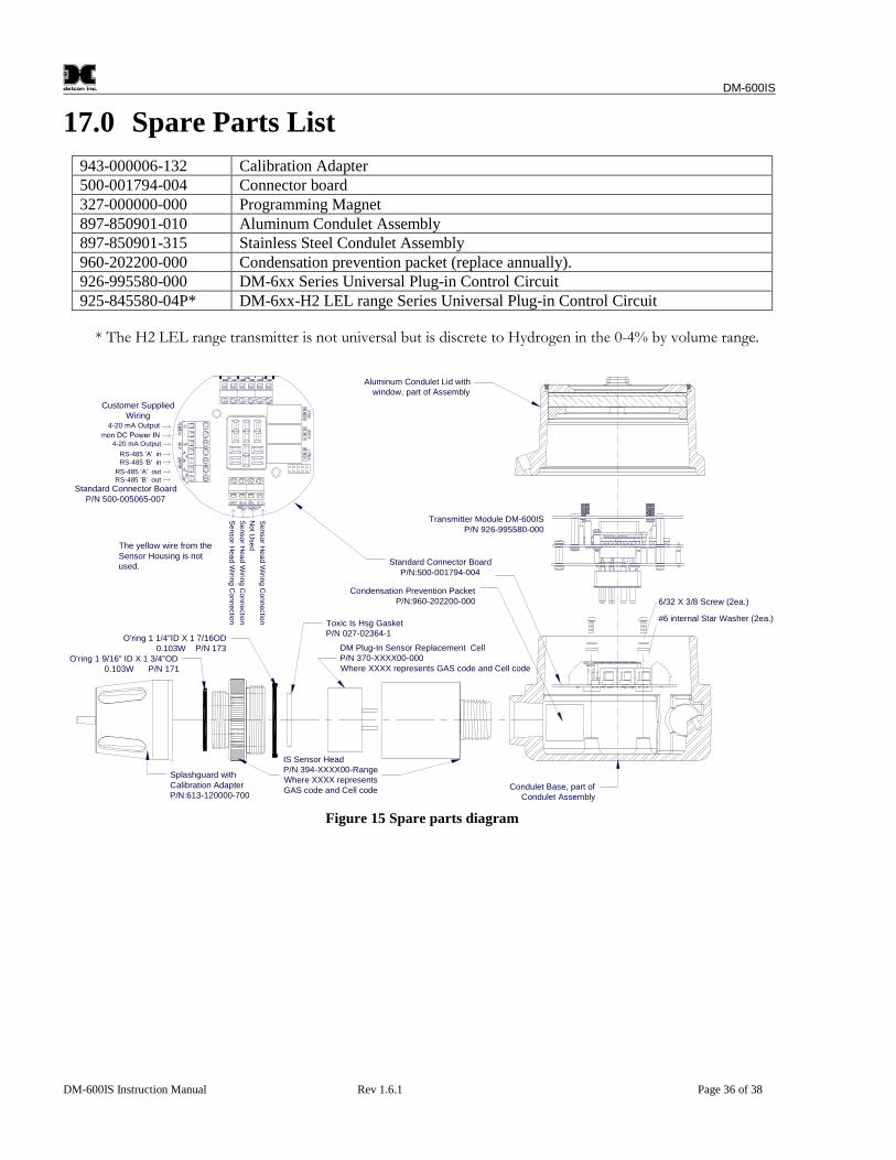
DM-600IS
DM-600IS Instruction Manual Rev 1.6.1 Page 36 of 38
17.0 Spare Parts List
943-000006-132 Calibration Adapter500-001794-004 Connector board327-000000-000 Programming Magnet897-850901-010 Aluminum Condulet Assembly897-850901-315 Stainless Steel Condulet Assembly960-202200-000 Condensation prevention packet (replace annually).926-995580-000 DM-6xx Series Universal Plug-in Control Circuit925-845580-04P* DM-6xx-H2 LEL range Series Universal Plug-in Control Circuit
* The H2 LEL range transmitter is not universal but is discrete to Hydrogen in the 0-4% by volume range.
NotU
sed
Sensor
Head
Wirin
gC
onnectio
n
Sensor
Head
Wirin
gC
onnectio
n
Sensor
Head
Wirin
gC
onnectio
n
4-20 mA Output
Customer SuppliedWiring
4-20 mA Output
RS-485 'A' inRS-485 'B' in
RS-485 'A' outRS-485 'B' out
6/32 X 3/8 Screw (2ea.)
#6 internal Star Washer (2ea.)
DM Plug-In Sensor Replacement CellP/N 370-XXXX00-000Where XXXX represents GAS code and Cell code
Transmitter Module DM-600ISP/N 926-995580-000
Standard Connector BoardP/N 500-005065-007
IS Sensor HeadP/N 394-XXXX00-RangeWhere XXXX representsGAS code and Cell code Condulet Base, part of
Condulet Assembly
Splashguard withCalibration AdapterP/N:613-120000-700
Condensation Prevention PacketP/N:960-202200-000
Standard Connector BoardP/N:500-001794-004
Toxic Is Hsg GasketP/N 027-02364-1
O'ring 1 1/4"ID X 1 7/16OD0.103W P/N 173
Aluminum Condulet Lid withwindow, part of Assembly
O'ring 1 9/16" ID X 1 3/4"OD0.103W P/N 171
The yellow wire from theSensor Housing is notused.
Figure 15 Spare parts diagram
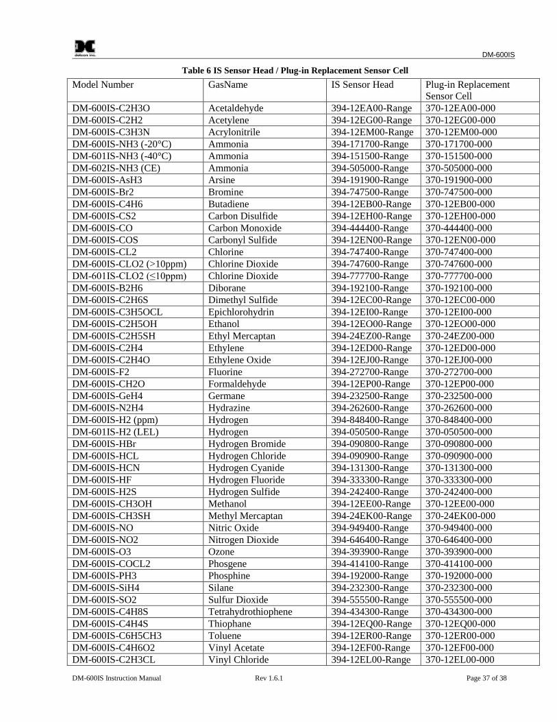
DM-600IS
DM-600IS Instruction Manual Rev 1.6.1 Page 37 of 38
Table 6 IS Sensor Head / Plug-in Replacement Sensor Cell
Model Number GasName IS Sensor Head Plug-in ReplacementSensor Cell
DM-600IS-C2H3O Acetaldehyde 394-12EA00-Range 370-12EA00-000DM-600IS-C2H2 Acetylene 394-12EG00-Range 370-12EG00-000DM-600IS-C3H3N Acrylonitrile 394-12EM00-Range 370-12EM00-000DM-600IS-NH3 (-20°C) Ammonia 394-171700-Range 370-171700-000DM-601IS-NH3 (-40°C) Ammonia 394-151500-Range 370-151500-000DM-602IS-NH3 (CE) Ammonia 394-505000-Range 370-505000-000DM-600IS-AsH3 Arsine 394-191900-Range 370-191900-000DM-600IS-Br2 Bromine 394-747500-Range 370-747500-000DM-600IS-C4H6 Butadiene 394-12EB00-Range 370-12EB00-000DM-600IS-CS2 Carbon Disulfide 394-12EH00-Range 370-12EH00-000DM-600IS-CO Carbon Monoxide 394-444400-Range 370-444400-000DM-600IS-COS Carbonyl Sulfide 394-12EN00-Range 370-12EN00-000DM-600IS-CL2 Chlorine 394-747400-Range 370-747400-000DM-600IS-CLO2 (>10ppm) Chlorine Dioxide 394-747600-Range 370-747600-000DM-601IS-CLO2 (≤10ppm) Chlorine Dioxide 394-777700-Range 370-777700-000DM-600IS-B2H6 Diborane 394-192100-Range 370-192100-000DM-600IS-C2H6S Dimethyl Sulfide 394-12EC00-Range 370-12EC00-000DM-600IS-C3H5OCL Epichlorohydrin 394-12EI00-Range 370-12EI00-000DM-600IS-C2H5OH Ethanol 394-12EO00-Range 370-12EO00-000DM-600IS-C2H5SH Ethyl Mercaptan 394-24EZ00-Range 370-24EZ00-000DM-600IS-C2H4 Ethylene 394-12ED00-Range 370-12ED00-000DM-600IS-C2H4O Ethylene Oxide 394-12EJ00-Range 370-12EJ00-000DM-600IS-F2 Fluorine 394-272700-Range 370-272700-000DM-600IS-CH2O Formaldehyde 394-12EP00-Range 370-12EP00-000DM-600IS-GeH4 Germane 394-232500-Range 370-232500-000DM-600IS-N2H4 Hydrazine 394-262600-Range 370-262600-000DM-600IS-H2 (ppm) Hydrogen 394-848400-Range 370-848400-000DM-601IS-H2 (LEL) Hydrogen 394-050500-Range 370-050500-000DM-600IS-HBr Hydrogen Bromide 394-090800-Range 370-090800-000DM-600IS-HCL Hydrogen Chloride 394-090900-Range 370-090900-000DM-600IS-HCN Hydrogen Cyanide 394-131300-Range 370-131300-000DM-600IS-HF Hydrogen Fluoride 394-333300-Range 370-333300-000DM-600IS-H2S Hydrogen Sulfide 394-242400-Range 370-242400-000DM-600IS-CH3OH Methanol 394-12EE00-Range 370-12EE00-000DM-600IS-CH3SH Methyl Mercaptan 394-24EK00-Range 370-24EK00-000DM-600IS-NO Nitric Oxide 394-949400-Range 370-949400-000DM-600IS-NO2 Nitrogen Dioxide 394-646400-Range 370-646400-000DM-600IS-O3 Ozone 394-393900-Range 370-393900-000DM-600IS-COCL2 Phosgene 394-414100-Range 370-414100-000DM-600IS-PH3 Phosphine 394-192000-Range 370-192000-000DM-600IS-SiH4 Silane 394-232300-Range 370-232300-000DM-600IS-SO2 Sulfur Dioxide 394-555500-Range 370-555500-000DM-600IS-C4H8S Tetrahydrothiophene 394-434300-Range 370-434300-000DM-600IS-C4H4S Thiophane 394-12EQ00-Range 370-12EQ00-000DM-600IS-C6H5CH3 Toluene 394-12ER00-Range 370-12ER00-000DM-600IS-C4H6O2 Vinyl Acetate 394-12EF00-Range 370-12EF00-000DM-600IS-C2H3CL Vinyl Chloride 394-12EL00-Range 370-12EL00-000
DM-600IS
DM-600IS Instruction Manual Rev 1.6.1 Page 38 of 38
18.0 Warranty
Detcon, Inc., as manufacturer, warrants each new electrochemical toxic gas plug-in sensor cell, for a specifiedperiod under the conditions described as follows: The warranty period begins on the date of shipment to theoriginal purchaser and ends after the specified period as listed in the table in Section 4.0. The sensor cell iswarranted to be free from defects in material and workmanship. Should any sensor cell fail to perform inaccordance with published specifications within the warranty period, return the defective part to Detcon, Inc.,4055 Technology Forest Blvd. Suite 100, The Woodlands, Texas 77381, for necessary repairs or replacement.
19.0 Service Policy
Detcon, Inc., as manufacturer, warrants under intended normal use each new DM-600IS series plug-in signaltransmitter Control Circuit and intrinsically safe Sensor Head circuit to be free from defects in material andworkmanship for a period of two years from the date of shipment to the original purchaser. Detcon, Inc.,further provides for a five year fixed fee service policy wherein any failed signal Transmitter shall be repairedor replaced as is deemed necessary by Detcon, Inc., for a fixed fee of $65.00. Any failed intrinsically safeSensor Head circuit shall be repaired or replaced as is deemed necessary by Detcon, Inc., for a fixed fee of$55.00. The fixed fee service policy shall affect any factory repair for the period following the two yearwarranty and shall end five years after expiration of the warranty. All warranties and service policies are FOBthe Detcon facility located in The Woodlands, Texas.
20.0 Revision History
Revision Date Changes made Approval1.5.6 09/12/06 Previous release. BM1.5.7 11/19/10 Calibration adapter changed from 943-000217-5A1 to 943-
000006-132BM
1.5.8 11/08/10 Correction of wrong value in Cross Interference table. Value forCO interfering with C2H3CL was 12150=100, changed to200=100
BM
1.5.9 01/10/13 Converted manual from Quark to MS Word. Added statementabout maximum distance of sensor separation (Section 5.5)
BM
1.6.0 08/06/15 Correct wiring of Sensor and Remote Sensor LU1.6.1 08/17/15 Correct wiring of Sensor, update Spare Parts LU
Shipping Address 4055 Technology Forest Blvd. Suite 100,., The Woodlands Texas 77381Mailing Address: P.O. Box 8067, The Woodlands Texas 77387-8067
Phone: 888.367.4286, 281.367.4100 • Fax: 281.292.2860 • www.detcon.com • [email protected]
Related Documents