DISC MOWER DM SERIES / 7-8 USER’S AND MAINTENANCE MANUAL ENOAGRICOLA ROSSI s.r.l. 06018 Calzolaro di Umbertide – Perugia – Italy Tel. (39) 075-930 22 22 – Telefax (39) 075-930 23 28 e-mail: [email protected] – [email protected] web: http://www.enorossi.it - http://www.enoagricolarossi.com

Welcome message from author
This document is posted to help you gain knowledge. Please leave a comment to let me know what you think about it! Share it to your friends and learn new things together.
Transcript
�
DISC MOWER DM SERIES / 7-8 USER’S AND MAINTENANCE MANUAL
ENOAGRICOLA ROSSI s.r.l. 06018 Calzolaro di Umbertide – Perugia – Italy
Tel. (39) 075-930 22 22 – Telefax (39) 075-930 23 28
e-mail: [email protected] – [email protected]
web: http://www.enorossi.it - http://www.enoagricolarossi.com

ROTARY DMP 7-8 USER’S AND MAINTENANCE MANUAL Edition March 2010 - � Pagina 2 di 50
Contents Section 1 – General information ................................................................................................................................................................... 3 Section 2 – Use of the manual ..................................................................................................................................................................... 4 Section 3 – Machine assembly .................................................................................................................................................................... 6 Section 4 – Attachment of the machine to the tractor ................................................................................................................................. 14 Section 5 – Cardan shaft ........................................................................................................................................................................... 18 Section 6 – Transport position ................................................................................................................................................................... 19 Section 7 – Work position and adjustments ............................................................................................................................................... 21 Section 8 – Use of the mowing machine .................................................................................................................................................... 23 Section 9 – Adjustments for operation ....................................................................................................................................................... 24 Section 10 – Checks, maintenance, adjustments. ...................................................................................................................................... 27 Section 11 - Lubrication ............................................................................................................................................................................. 31 Section 12 – Requesting spare parts ......................................................................................................................................................... 35
This document is the property of ENOAGRICOLA ROSSI s.r.l. No parts herein may be reproduced without prior consent from the Company Management. Any infringements will be punished by law.
ROTARY DMP 7-8 USER’S AND MAINTENANCE MANUAL Edition March 2010 - � Pagina 3 di 50
Section 1 – General information
Assistance For any needs, contact the machine dealer or the ENOAGRICOLA ROSSI Technical Office.
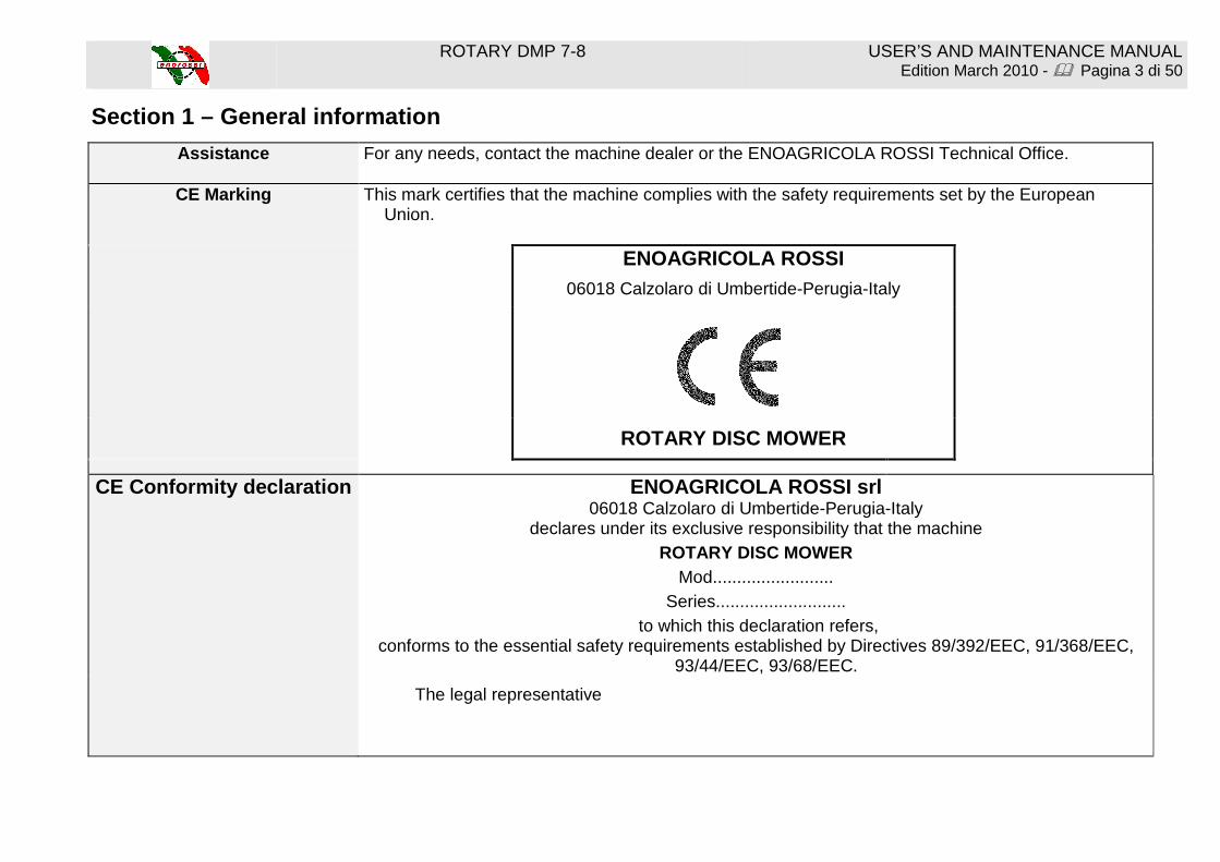
CE Marking This mark certifies that the machine complies with the safety requirements set by the European Union.
ENOAGRICOLA ROSSI
06018 Calzolaro di Umbertide-Perugia-Italy
ROTARY DISC MOWER
CE Conformity declaration ENOAGRICOLA ROSSI srl 06018 Calzolaro di Umbertide-Perugia-Italy
declares under its exclusive responsibility that the machine ROTARY DISC MOWER
Mod......................... Series...........................
to which this declaration refers, conforms to the essential safety requirements established by Directives 89/392/EEC, 91/368/EEC,
93/44/EEC, 93/68/EEC.
The legal representative

ROTARY DMP 7-8 USER’S AND MAINTENANCE MANUAL Edition March 2010 - � Pagina 4 di 50
Section 2 – Use of the manual
BEFORE INSTALLING AND USING THE MACHINE
OR BEFORE CARRYING OUT ANY OPERATION
READ CAREFULLY THE INSTRUCTIONS CONTAINED IN THIS M ANUAL ����
This manual has been written for your safety. It is an integral part of this machine and must be kept for reference at all
times, protecting it from moisture, neglect, and sunlight in order to prevent its deterioration.
The manual is intended for: the machine users, the owner, the safety supervisors, those in charge of handling, installation, use, supervision, maintenance, and final dismantling.
The manual provides indications on the correct use of the machine, its technical features, and safety measures; this
manual, in any case, can never replace an adequate experience of the user.
The manual also gives information for personnel training, for guiding maintenance operations, facilitating the request for spare parts, and warning about remaining risks that could not be eliminated in the design phase.
The manual reflects the state of the machine’s technical status as sold and cannot be considered inadequate if
subsequently updated on the basis of new experience.
The company supplying the machine reserves the right to make any changes to the product and its manual without the obligation to update previous production and related manuals.
N.B. Enoagricola Rossi accepts no liability for damages resulting from improper use by untrained personnel, use not in
accordance with national and Community workplace safety requirements, incorrect installation, serious deficiencies in the required maintenance, unauthorized changes or repairs, use of unauthorised spare parts, acts of God, or total or partial failure to follow the instructions contained in this manual.

ROTARY DMP 7-8 USER’S AND MAINTENANCE MANUAL Edition March 2010 - � Pagina 5 di 50
The machine has been designed in conformity with European machine safety standards and, in particular, the following standards have been considered: 1. EN 292/2 Ed. 1991: Safety of machine. Fundamental concepts and general principles of mechanical design. Technical
specifications and principles. 2. ISO 7000 Ed. 1994: Safety decals to be used on machine.
The machine must be used by operators who: 1. Have a good knowledge of safety standards and regulations. 2. Are well informed on risks of this machine and dangerous areas and on the importance of not tampering with protection
guards. 3. Have been well trained on how to operate the machine. 4. Will inform manufacturer of any malfunctioning.
���� In the event this manual is lost or damaged, a new copy may be requested from this address:
ENOAGRICOLA ROSSI Srl 06018 Calzolaro di Umbertide – Perugia – Italy
Tel 075 / 930 22 22 Fax 075 / 930 23 28
IMPORTANT! If the machine is sold, please turn this manual over to the new owner.
ROTARY DMP 7-8 USER’S AND MAINTENANCE MANUAL Edition March 2010 - � Pagina 6 di 50
Section 3 – Machine assembly
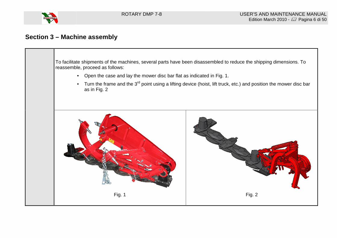
To facilitate shipments of the machines, several parts have been disassembled to reduce the shipping dimensions. To reassemble, proceed as follows:
• Open the case and lay the mower disc bar flat as indicated in Fig. 1.
• Turn the frame and the 3rd point using a lifting device (hoist, lift truck, etc.) and position the mower disc bar as in Fig. 2
Fig. 1
Fig. 2

ROTARY DMP 7-8 USER’S AND MAINTENANCE MANUAL Edition March 2010 - � Pagina 7 di 50
1st assembly – assembly of the protection support. Mount protection support A (Fig. 3 – Fig. 3/A) in gear case B; first of all, connect the lifting rod hole to support D (Fig. 3). Fasten the support with screws C (screw T.E. M12x50 and washer M12 Y and spacer J.
2nd assembly – assembly of the protection bar (only on DM-P series). Position the protection bar E in support A (Fig. 4) and fasten it with six screws F (screw T.E. M10x35), six washers, and six self-locking nuts G M10 (only on DM-P series).
Fig. 3/A
Fig. 3
Fig. 4
ROTARY DMP 7-8 USER’S AND MAINTENANCE MANUAL Edition March 2010 - � Pagina 8 di 50
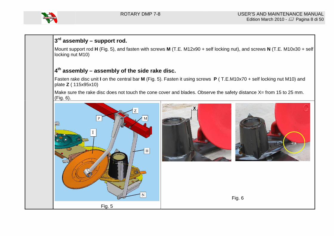
3rd assembly – support rod.
Mount support rod H (Fig. 5), and fasten with screws M (T.E. M12x90 + self locking nut), and screws N (T.E. M10x30 + self locking nut M10)
4th assembly – assembly of the side rake disc. Fasten rake disc unit I on the central bar M (Fig. 5). Fasten it using screws P ( T.E.M10x70 + self locking nut M10) and plate Z ( 115x95x10)
Make sure the rake disc does not touch the cone cover and blades. Observe the safety distance X= from 15 to 25 mm. (Fig. 6).
Fig. 5
Fig. 6
ROTARY DMP 7-8 USER’S AND MAINTENANCE MANUAL Edition March 2010 - � Pagina 9 di 50
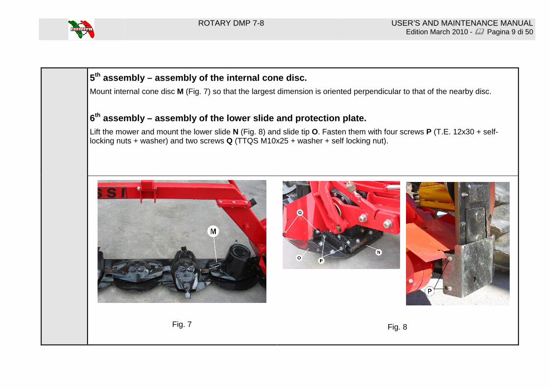
5th assembly – assembly of the internal cone disc. Mount internal cone disc M (Fig. 7) so that the largest dimension is oriented perpendicular to that of the nearby disc.
6th assembly – assembly of the lower slide and protect ion plate. Lift the mower and mount the lower slide N (Fig. 8) and slide tip O. Fasten them with four screws P (T.E. 12x30 + self-locking nuts + washer) and two screws Q (TTQS M10x25 + washer + self locking nut).
Fig. 7
Fig. 8

ROTARY DMP 7-8 USER’S AND MAINTENANCE MANUAL Edition March 2010 - � Pagina 10 di 50
7th assembly – assembly of internal protective flap. Mount flap R (Fig. 9) protecting the gear case and fasten it with connecting bracket S and three screws T (TTQS M10x25 + washer + self locking nut). To facilitate assembly of flap R, it is advisable to insert all screws before starting to tighten them.
8th assembly – assembly of the belt protection case. Mount case U (Fig. 10), fasten with screws V (T.E. M10x120), washers and self-blocking nuts (M10).
Fig. 9
Fig. 10
ROTARY DMP 7-8 USER’S AND MAINTENANCE MANUAL Edition March 2010 - � Pagina 11 di 50
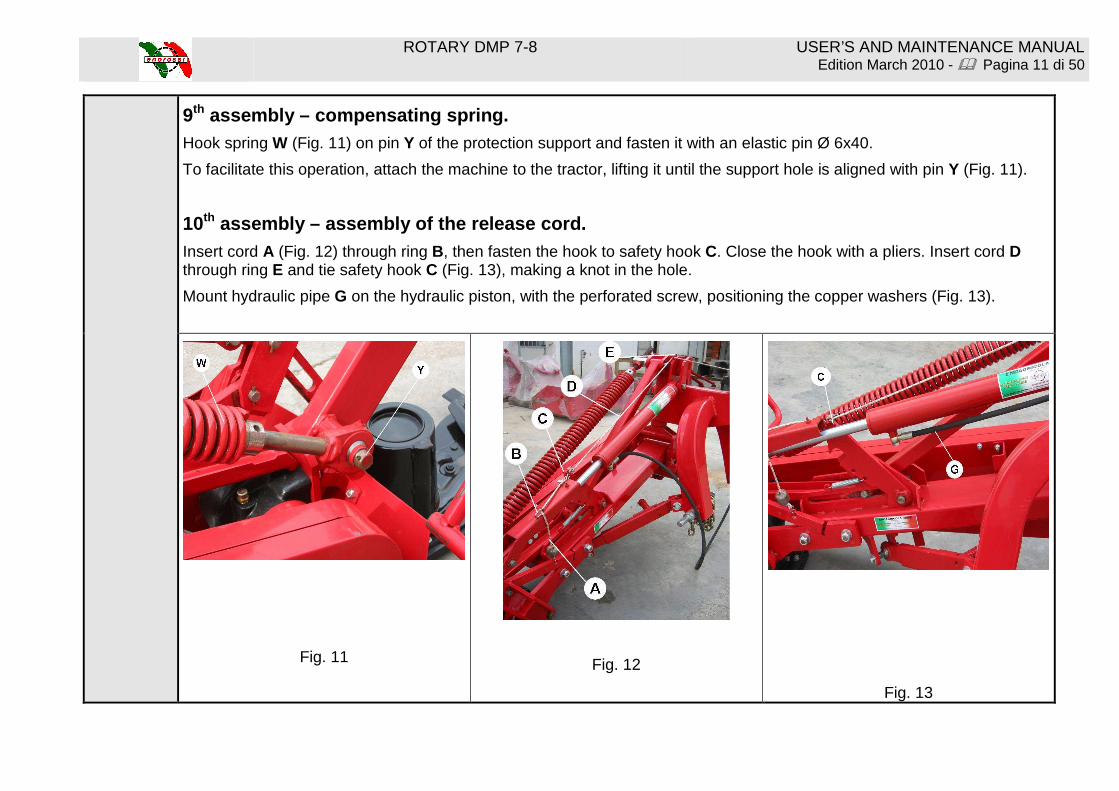
9th assembly – compensating spring. Hook spring W (Fig. 11) on pin Y of the protection support and fasten it with an elastic pin Ø 6x40.
To facilitate this operation, attach the machine to the tractor, lifting it until the support hole is aligned with pin Y (Fig. 11).
10th assembly – assembly of the release cord. Insert cord A (Fig. 12) through ring B, then fasten the hook to safety hook C. Close the hook with a pliers. Insert cord D through ring E and tie safety hook C (Fig. 13), making a knot in the hole.
Mount hydraulic pipe G on the hydraulic piston, with the perforated screw, positioning the copper washers (Fig. 13).
Fig. 11
Fig. 12
Fig. 13
ROTARY DMP 7-8 USER’S AND MAINTENANCE MANUAL Edition March 2010 - � Pagina 12 di 50
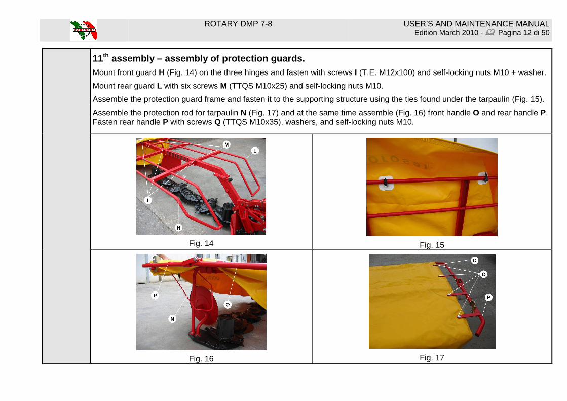
11th assembly – assembly of protection guards. Mount front guard H (Fig. 14) on the three hinges and fasten with screws I (T.E. M12x100) and self-locking nuts M10 + washer.
Mount rear guard L with six screws M (TTQS M10x25) and self-locking nuts M10.
Assemble the protection guard frame and fasten it to the supporting structure using the ties found under the tarpaulin (Fig. 15).
Assemble the protection rod for tarpaulin N (Fig. 17) and at the same time assemble (Fig. 16) front handle O and rear handle P. Fasten rear handle P with screws Q (TTQS M10x35), washers, and self-locking nuts M10.
Fig. 14
Fig. 15
Fig. 16
Fig. 17
ROTARY DMP 7-8 USER’S AND MAINTENANCE MANUAL Edition March 2010 - � Pagina 13 di 50
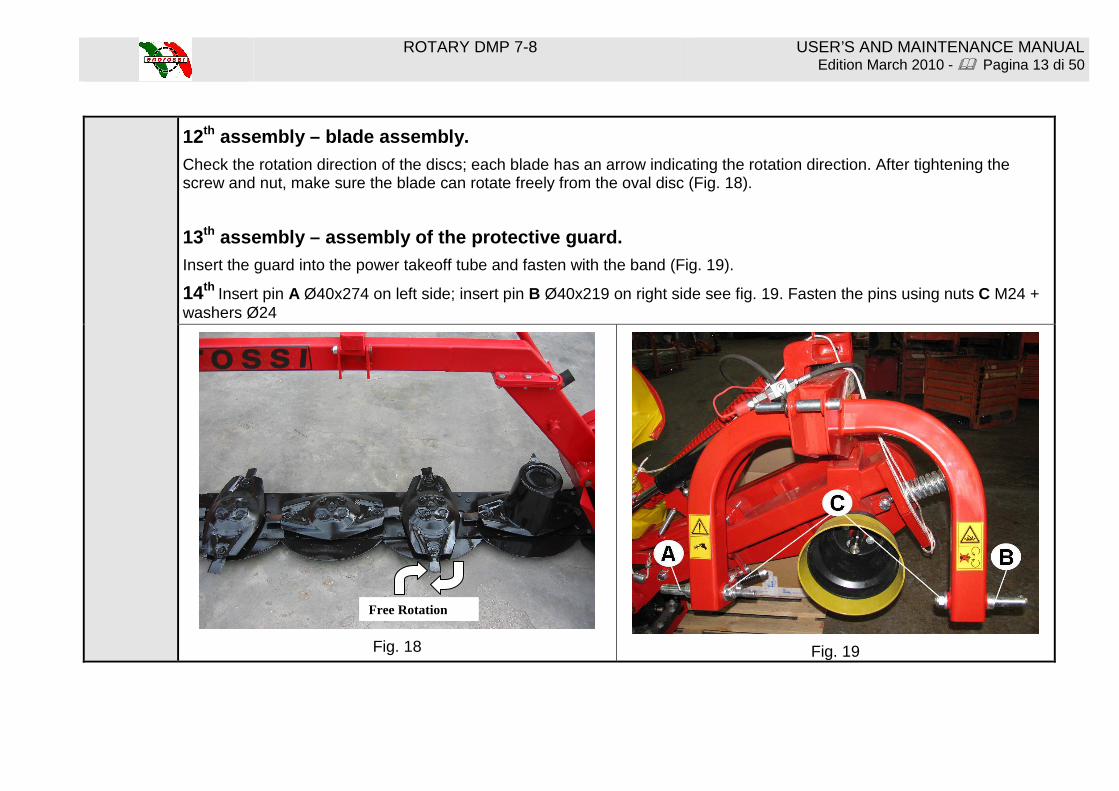
12th assembly – blade assembly.
Check the rotation direction of the discs; each blade has an arrow indicating the rotation direction. After tightening the screw and nut, make sure the blade can rotate freely from the oval disc (Fig. 18).
13th assembly – assembly of the protective guard. Insert the guard into the power takeoff tube and fasten with the band (Fig. 19).
14th Insert pin A Ø40x274 on left side; insert pin B Ø40x219 on right side see fig. 19. Fasten the pins using nuts C M24 + washers Ø24
Fig. 18
Fig. 19
Free Rotation

ROTARY DMP 7-8 USER’S AND MAINTENANCE MANUAL Edition March 2010 - � Pagina 14 di 50
Section 4 – Attachment of the machine to the tracto r NB: The mower must be attached to a tractor with a power takeoff of 540
rpm and to a 3-point attachment (Fig. 20).
Fig. 20
Instructions for attachment to the tractor:
Fig. 21
1) Insert the tractor’s lifting arms A (Fig. 20) into attachment pins B and fasten them with split pins.
2) Insert 3rd point C and fasten it with pin D (Fig. 20).
3) Connect the hydraulic pipe of the piston to the tractor’s distributor (Fig. 21)

ROTARY DMP 7-8 USER’S AND MAINTENANCE MANUAL Edition March 2010 - � Pagina 15 di 50
4) Connect the tractor’s cardan shaft to the power takeoff of the mower;
use chains to prevent rotation of the protection pipe.
Fig. 22
5) Lift the machine using the hydraulic lift; turn edge E upwards (Fig. 22)
6) IMPORTANT!!! During work and transport, edge E must always be turned upwards as in Fig. 23.
Fig. 23

ROTARY DMP 7-8 USER’S AND MAINTENANCE MANUAL Edition March 2010 - � Pagina 16 di 50
7) ADJUSTMENT OF FRAME HEIGHT FROM THE GROUND.
A - for tractors equipped with hydraulic lift position control:
Position the tractor on level ground and lower the hydraulic lift until the lifting lever F is positioned at a distance of 4 mm from the edge, as shown in Fig. 24.
Fig. 24
After adjusting the height of the mower frame, set the lift control from the tractor driver’s seat. In this case it is not necessary to use the limiting chain supplied with the machine.

ROTARY DMP 7-8 USER’S AND MAINTENANCE MANUAL Edition March 2010 - � Pagina 17 di 50
B – for tractors not equipped with hydraulic lift posit ion control:
The chain supplied with the machine must be used.
Fasten bracket G (Fig. 25) and the limiting chain H supplied, to one of the free holes of the tractor’s third point.
Lower the machine to work position, until lifting lever F is positioned at a distance of 4 mm from the edge, as shown in Fig. 24. Limiting chain H must be taut (Fig. 25), and the lifting lever must be at a distance of 4 mm. as per Fig. 24.
To be able to always recognize this position, mark the chain ring that will be hooked with bracket G.
Fig. 25

ROTARY DMP 7-8 USER’S AND MAINTENANCE MANUAL Edition March 2010 - � Pagina 18 di 50
Section 5 – Cardan shaft
The cardan shaft supplied with the mower is of the correct size for coupling with most tractors on the market. In any case, before starting work for the first time, it is advisable to check its length. If adaptation is required, proceed as follows: Important! Use only the cardan shaft supplied or recommended, otherwise any warranty claim or request will be considered null and void. If the cardan shaft is too long, open the two halves and overlap them; this way it will be possible to determine how much longer it is in cm. Cut both tubes of the internal and external cardan shaft to the same length, as well as their guards. Clean the cut edges of the tubes with a file, grease them, and reclose the cardan shaft. Important! The maximum work length (L1) must allow an overlapping of the tubes equal to half the length of the closed cardan shaft (min. _X). Always make sure that the cardan shaft is correctly tightened before starting work Support chain Use the chain to prevent rotation of the protection tube. Make sure that the chain does not hamper the side movements of the cardan shaft.

ROTARY DMP 7-8 USER’S AND MAINTENANCE MANUAL Edition March 2010 - � Pagina 19 di 50
Section 6 – Transport position
Before moving the mower into transport position, send away all persons who may be in the manoeuvring area.
To position for road transport or for moving from one field to another, carry out the following operations:
1) Disconnect the tractor power takeoff, and make sure the discs have stopped rotating.
2) Turn front guard I backward until the fastening point with hook L (Fig. 26).
Fig. 26
3) Lift the bar using the tractor’s hydraulic lift, positioning lower slide M at about 15-20 cm from the ground (Fig. 27).
Fig. 27
4) Edge E must be turned upwards (Fig. 22 – Fig. 23 Pag. 15).

ROTARY DMP 7-8 USER’S AND MAINTENANCE MANUAL Edition March 2010 - � Pagina 20 di 50
5) Pull cord O to free lifting lever P (Fig. 28).
Fig. 28
6) Slowly lift the mower to a vertical position, using the hydraulic hitch. Release the traction of cord O (Fig. 29) while raising the bar vertically; it will automatically hook up, for transport, with safety hook P1.
Fig. 29

ROTARY DMP 7-8 USER’S AND MAINTENANCE MANUAL Edition March 2010 - � Pagina 21 di 50
Section 7 – Work position and adjustment Before moving the mower into the work position, send away
all persons who may be in the manoeuvring area.
To switch the bar from transport position to work position, carry out the following operations:
1) give pressure to the hydraulic hitch to lighten the weight on safety hook P1 (Fig. 30).
Fig. 30
2) Pull cord O to free the bar from safety hook P1 (Fig. 30).
3) Lower the mower using the hydraulic cylinder until it reaches the work position.

ROTARY DMP 7-8 USER’S AND MAINTENANCE MANUAL Edition March 2010 - � Pagina 22 di 50
4) Turn the front tarpaulin carrier over forward.
(Fig. 31)
Fig. 31
5) Check the height of the frame from the ground.
Lifting lever F (Fig. 24, Page 20) must be positioned at a distance of 4 mm from the edge.

ROTARY DMP 7-8 USER’S AND MAINTENANCE MANUAL Edition March 2010 - � Pagina 23 di 50
Section 8 – Use of the mowing machine
Before starting work, make sure that there are no persons close to the work area.
Check that protective guards are lowered and the protective tarpaulin is covering the cutting bar.
At this point, carry out the manoeuvres listed below:
1) Connect the tractor’s power takeoff and accelerate progressively until reaching 540 rpm.
2) The advancement speed must be appropriate for the working conditions. Reduce speed when changing direction.
3) When work is finished, gradually reduce the speed of the power takeoff, then disconnect it.
IMPORTANT!!!! Do not mow in extremely stony or rocky areas.
4) During work, the tractor’s hydraulic distributor must always be in floating position in order to permit an adequate adaptability to the irregularities of the terrain.
The mowing bar can be raised from the ground using the hydraulic cylinder (Fig. 32).
5) Raise the mowing bar using the hydraulic cylinder until the cylinder edge R reaches its limit (Fig. 33).
Fig. 32
Fig. 33

ROTARY DMP 7-8 USER’S AND MAINTENANCE MANUAL Edition March 2010 - � Pagina 24 di 50
Section 9 – Adjustments for operation
Adjustment of the side rake disc. Position the rake disc in order to have the greatest distance between the uncut forage and the windrow.
To set the disc in the correct position loosen the 4 screws pos. A and move to right or left the disc support see fig.34. Once you reach the right position fasten the 4 screws pos. A
Fig. 34
Adjustment of cutting height. The maximum and minimum cutting heights are obtained by changing the tilt of the mowing bar, by varying the length of the third point C (Fig. 35), until the desired cutting height is obtained. The minimum height must be no less than 30 mm.
Fig. 35
ROTARY DMP 7-8 USER’S AND MAINTENANCE MANUAL Edition March 2010 - � Pagina 25 di 50
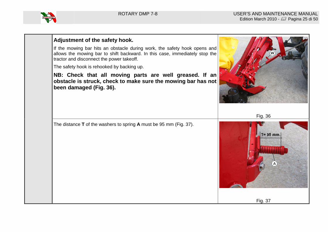
Adjustment of the safety hook.
If the mowing bar hits an obstacle during work, the safety hook opens and allows the mowing bar to shift backward. In this case, immediately stop the tractor and disconnect the power takeoff.
The safety hook is rehooked by backing up.
NB: Check that all moving parts are well greased. I f an obstacle is struck, check to make sure the mowing b ar has not been damaged (Fig. 36).
Fig. 36
The distance T of the washers to spring A must be 95 mm (Fig. 37).
Fig. 37

ROTARY DMP 7-8 USER’S AND MAINTENANCE MANUAL Edition March 2010 - � Pagina 26 di 50
Detachment of the machine from the tractor.
1) Using the hydraulic hitch, lower the disc mower to a horizontal position. Unlock edge N and turn it downwards (see arrow) onto transfer case U (Fig. 38 – Fig. 39).
Fig. 38
Fig. 39
2) Lower the tractor’s hydraulic lift, to lower the machine to the ground.
3) Disconnect the third point and remove the hydraulic tube, closing the tap V (Fig. 40).
Fig. 40
4) Disconnect the towing bars and cardan shaft.

ROTARY DMP 7-8 USER’S AND MAINTENANCE MANUAL Edition March 2010 - � Pagina 27 di 50
Section 10 – Checks, maintenance, adjustments.
IMPORTANT!!! Before proceeding with any maintenance or adjustment, turn off the tractor engine, remove the keys, and disconnect the cardan shaft.
1) Checking of discs and blades. The discs, blades, and fastening screws are made of a special high-quality steel and heat-treated to increase their durability and resistance to wear.
Worn or damaged parts must be immediately replaced with original ENOROSSI parts, otherwise it will not be possible to make any warranty claims or requests.
2) Checking of blade-carrying pins. Make regular checks of the condition of the blade pins every 50 work hours, and check them more often if work is done on rocky terrain or in difficult conditions.
Check them immediately in the case of violent blows (stones, pieces of wood, etc.).
Replace the blade pin if it is deformed or deteriorated.
Replace the blade pin if the screw head is worn or deteriorated.
Replace the blade pin if the screw head measures less than 13-15 mm (D) (Fig. 41).
Fig. 41

ROTARY DMP 7-8 USER’S AND MAINTENANCE MANUAL Edition March 2010 - � Pagina 28 di 50
3) Checking of fastening screws.
Replace the nut when the locking washer has lost its elasticity. Replace the nut if it shows evident consumption (Fig. 42).
Fig. 42
4) Checking of blades. Blade replacement.
Rotate the disc perpendicularly (Fig. 43) to the mowing bar and unscrew the nut projecting above the disc using a 19 wrench. Pull out the blade holder from underneath the disc and remove the blade.
Pay attention to the rotation direction of the disc (Fig. 43) and assemble the blade according to the same rotation direction (as indicated by the arrow printed on the blade). All blades on the same disc are the same.
Use original ENOROSSI spare parts.
For your safety, and for a better cutting quality, make systematic checks of the wear condition of the blades before every use of the mower.
Fig. 43

ROTARY DMP 7-8 USER’S AND MAINTENANCE MANUAL Edition March 2010 - � Pagina 29 di 50
Change blades immediately if they are damaged, because if work is done occasionally in difficult conditions, the risk of accidents increases, the cutting quality decreases, and vibrations may also damage the disc support.
Replace blades immediately when they are worn down. Blades should be at least 90 mm long (A) and 30 mm wide (B) (Fig. 44).
Replace the blade if the hole has become ovalized to more than 4 mm (L) (Fig. 44).
IMPORTANT!! Make regular checks of the tightness of all fastening screws and nuts, in particular those that hold blades and discs.
Fig. 44

ROTARY DMP 7-8 USER’S AND MAINTENANCE MANUAL Edition March 2010 - � Pagina 30 di 50
5) Checking of belts (tension adjustment).
To prevent belt slippage, it is necessary to periodically check the belt tension.
To increase tension, tighten nut A on the threaded bar (Fig. 45).
It is very important for the belt tension to be checked after the first hours of work, and later with weekly checks.
Fig. 45
6) Adjustment of the compensating spring. The spring tension is regulated in the factory; the tension may be changed as follows:
Lift the mower until spring B (Fig. 46) is taut. Loosen lock nut C and turn D to reduce or increase tension. After regulating, lock with locknut C.
Fig. 46
ROTARY DMP 7-8 USER’S AND MAINTENANCE MANUAL Edition March 2010 - � Pagina 31 di 50
Section 11 - Lubrication
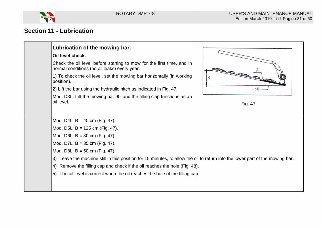
Lubrication of the mowing bar. Oil level check.
Check the oil level before starting to mow for the first time, and in normal conditions (no oil leaks) every year.
1) To check the oil level, set the mowing bar horizontally (in working position).
2) Lift the bar using the hydraulic hitch as indicated in Fig. 47.
Mod. D3L: Lift the mowing bar 90° and the filling c ap functions as an oil level. Fig. 47
Mod. D4L: B = 40 cm (Fig. 47).
Mod. D5L: B = 125 cm (Fig. 47).
Mod. D6L: B = 30 cm (Fig. 47).
Mod. D7L: B = 35 cm (Fig. 47).
Mod. D8L: B = 50 cm (Fig. 47).
3) Leave the machine still in this position for 15 minutes, to allow the oil to return into the lower part of the mowing bar.
4) Remove the filling cap and check if the oil reaches the hole (Fig. 48).
5) The oil level is correct when the oil reaches the hole of the filling cap.

ROTARY DMP 7-8 USER’S AND MAINTENANCE MANUAL Edition March 2010 - � Pagina 32 di 50
Position of the filling cap.
Mod. D3L-D4L-D5L: between the gear case and the first disc (Fig. 48).
Mod. D5L-D6L-D7L: between the first and second disc (Fig. 48).
Mod. D8L: between the second and third disc.
Fig. 48
Oil replacement.
The oil must be replaced completely after the first 50 hours of work, or at least after 100 hectares mowed.
Lift the mowing bar to a vertical position (Fig. 49). Remove the drainage cap situated at the bottom of the mowing bar and let the oil flow out, taking care to collect and dispose of it in accordance with the waste disposal laws and provisions in force.
Fig. 49
ROTARY DMP 7-8 USER’S AND MAINTENANCE MANUAL Edition March 2010 - � Pagina 33 di 50
Oil replacement must be carried out using hot oil (check that it is not
too hot, in order to prevent burns), since in this case the oil is more fluid and flows out more rapidly, preventing the old, much denser oil remaining inside the bar.
Fill through the filling cap situated on the upper part of the mowing bar.
Use type SAE 80W90 oil.
Oil quantity:
D3L: 1.5 litres
D4L: 2 litres
D5L: 2.5 litres
D6L: 3 litres
D7L: 3.5 litres
D8L: 4 litres
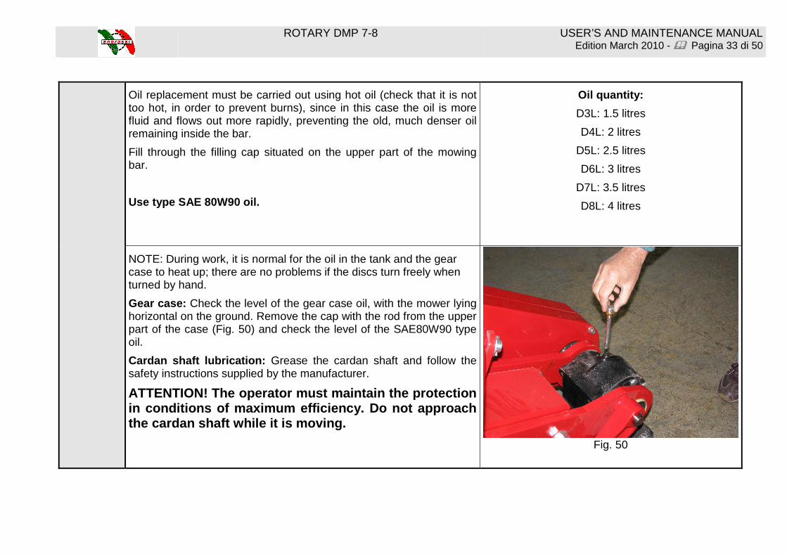
NOTE: During work, it is normal for the oil in the tank and the gear case to heat up; there are no problems if the discs turn freely when turned by hand.
Gear case: Check the level of the gear case oil, with the mower lying horizontal on the ground. Remove the cap with the rod from the upper part of the case (Fig. 50) and check the level of the SAE80W90 type oil.
Cardan shaft lubrication: Grease the cardan shaft and follow the safety instructions supplied by the manufacturer.
ATTENTION! The operator must maintain the protection in conditions of maximum efficiency. Do not approac h the cardan shaft while it is moving.
Fig. 50

ROTARY DMP 7-8 USER’S AND MAINTENANCE MANUAL Edition March 2010 - � Pagina 34 di 50

ROTARY DMP 7-8 USER’S AND MAINTENANCE MANUAL Edition March 2010 - � Pagina 35 di 50
Section 12 – Requesting spare parts
HOW TO CONTACT ENOAGRICOLA ROSSI The ENOAGRICOLA ROSSI customer help and spare parts service is at your disposal. To order spare parts, photocopy this page, fill it out with the requested information, and send it by mail or fax to:
ENOAGRICOLA ROSSI s.r.l. 06018 Calzolaro di Umbertide – Perugia – Italy
Tel. (39) 075-930 22 22 - Telefax (39) 075-930 23 28
To facilitate assistance and/or the supply of spare parts, please always provide the following information:
First & last name or Company name
Fiscal Code and/or VAT No.
Billing address Shipping address (if different from above)
Ref. # Code Description Quantity

ROTARY DMP 7-8 USER’S AND MAINTENANCE MANUAL Edition March 2010 - � Pagina 36 di 50
TABLE 1 COD. 19010482
ROTARY DMP 7-8 USER’S AND MAINTENANCE MANUAL Edition March 2010 - � Pagina 37 di 50
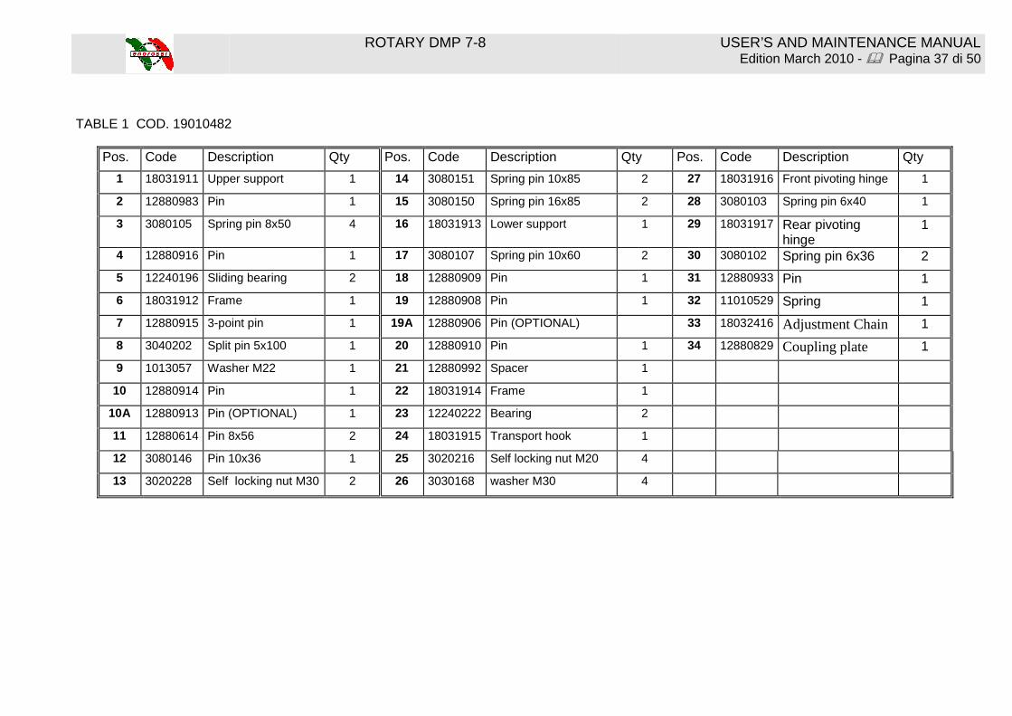
TABLE 1 COD. 19010482
Pos. Code Description Qty Pos. Code Description Qty Pos. Code Description Qty
1 18031911 Upper support 1 14 3080151 Spring pin 10x85 2 27 18031916 Front pivoting hinge 1
2 12880983 Pin 1 15 3080150 Spring pin 16x85 2 28 3080103 Spring pin 6x40 1
3 3080105 Spring pin 8x50 4 16 18031913 Lower support 1 29 18031917 Rear pivoting hinge
1
4 12880916 Pin 1 17 3080107 Spring pin 10x60 2 30 3080102 Spring pin 6x36 2
5 12240196 Sliding bearing 2 18 12880909 Pin 1 31 12880933 Pin 1
6 18031912 Frame 1 19 12880908 Pin 1 32 11010529 Spring 1
7 12880915 3-point pin 1 19A 12880906 Pin (OPTIONAL) 33 18032416 Adjustment Chain 1
8 3040202 Split pin 5x100 1 20 12880910 Pin 1 34 12880829 Coupling plate 1
9 1013057 Washer M22 1 21 12880992 Spacer 1
10 12880914 Pin 1 22 18031914 Frame 1
10A 12880913 Pin (OPTIONAL) 1 23 12240222 Bearing 2
11 12880614 Pin 8x56 2 24 18031915 Transport hook 1
12 3080146 Pin 10x36 1 25 3020216 Self locking nut M20 4
13 3020228 Self locking nut M30 2 26 3030168 washer M30 4
ROTARY DMP 7-8 USER’S AND MAINTENANCE MANUAL Edition March 2010 - � Pagina 38 di 50
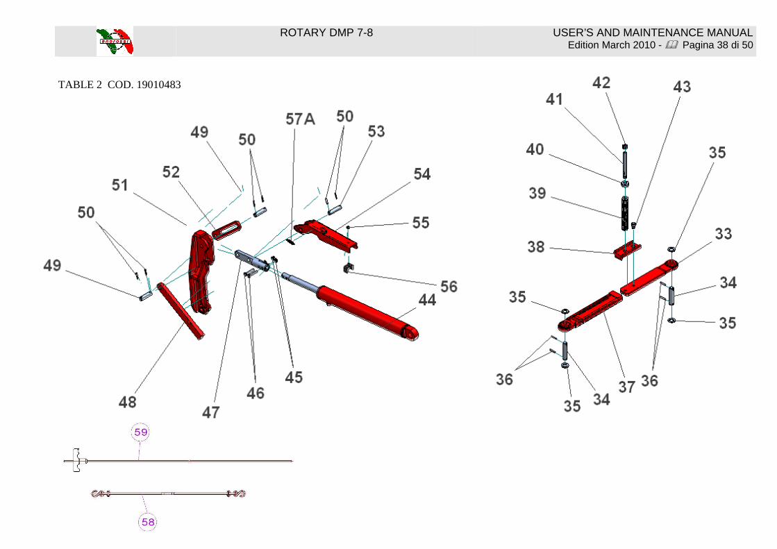
TABLE 2 COD. 19010483
ROTARY DMP 7-8 USER’S AND MAINTENANCE MANUAL Edition March 2010 - � Pagina 39 di 50
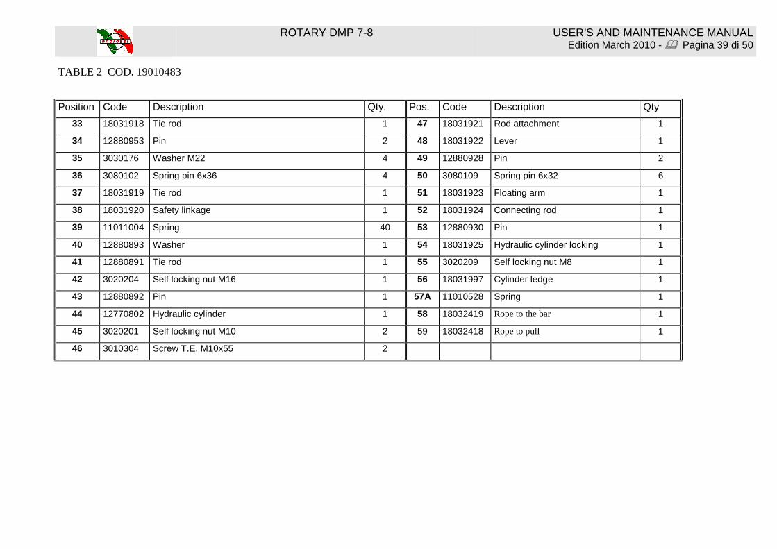
TABLE 2 COD. 19010483
Position Code Description Qty. Pos. Code Description Qty
33 18031918 Tie rod 1 47 18031921 Rod attachment 1
34 12880953 Pin 2 48 18031922 Lever 1
35 3030176 Washer M22 4 49 12880928 Pin 2
36 3080102 Spring pin 6x36 4 50 3080109 Spring pin 6x32 6
37 18031919 Tie rod 1 51 18031923 Floating arm 1
38 18031920 Safety linkage 1 52 18031924 Connecting rod 1
39 11011004 Spring 40 53 12880930 Pin 1
40 12880893 Washer 1 54 18031925 Hydraulic cylinder locking 1
41 12880891 Tie rod 1 55 3020209 Self locking nut M8 1
42 3020204 Self locking nut M16 1 56 18031997 Cylinder ledge 1
43 12880892 Pin 1 57A 11010528 Spring 1
44 12770802 Hydraulic cylinder 1 58 18032419 Rope to the bar 1
45 3020201 Self locking nut M10 2 59 18032418 Rope to pull 1
46 3010304 Screw T.E. M10x55 2

ROTARY DMP 7-8 USER’S AND MAINTENANCE MANUAL Edition March 2010 - � Pagina 40 di 50
TABLE 3 COD. 19010484

ROTARY DMP 7-8 USER’S AND MAINTENANCE MANUAL Edition March 2010 - � Pagina 41 di 50
TABLE 3 COD. 19010484
Pos. Code Description Qty Pos. Code Description Qty
57 18031926 Tie rod 1 70 3011672 Screw T.E. M6x16 4
58 3020416 Nut M27x2 2 71 18032406 Hinge screw M20x2,5 1
59 12880998 Bushing 1 72 3030168 Washer M20 2
60 11010623 Spring 1 73 12880985 Washer 2
61 18031927 Tie rod 1 74 11010624 Spring 1
62 12880904 Bushing 1 75 3020235 Self locking nut M20X2,5 1
63 12250019 Support 1 76 3080109 Split pin 6x32 2
64 3120146 Ring E35 2 77 12880903 Pin 1
65 18031928 Shaft 1
66 12240145 Bearing 6207 2RSR 2
67 18031929 Support 1
68 9070103 Cover 1
69 3030124 Washer M6 4

ROTARY DMP 7-8 USER’S AND MAINTENANCE MANUAL Edition March 2010 - � Pagina 42 di 50
78
79
82
85
90
80
81
88
8791
91
87
80
86
87
84
83
108 109 110
89 83
98
100100 100100 96 106 101
101
101
101
1029797 107
TABLE 4 COD. 19010485

ROTARY DMP 7-8 USER’S AND MAINTENANCE MANUAL Edition March 2010 - � Pagina 43 di 50
TABLE 4 COD. 19010485
Pos. Code Description Qty. Pos. Code Description Qty.
78 18032408 Internal cover 1 95 18031934 Bar ledge 1
79 2030117 Pulley 1 96 18032425 Disc support 1
80 12660315 Friction locking assembly 2 97 12240101 bearing 6005 2RSR 2
81 8020554 Belt 4 98 18031936 Disc 1
82 18031932 Outer cover 1 99 3030162 Washer M12 4
83 3030159 Washer M10 16 100 3020201 Self locking nut M10 2
84 3011304 Screw T.E. M10x120 8 101 3011277 Screw T.E. M10x80 2
85 2030118 Pulley 1 102 3120110 Split ring E25 1
86 3011241 Screw T.E. M12x30 4 103 11010531 Spring 2
87 3030162 Washer M12 10 104 3020329 Nut M8 z. 2
88 3011305 Screw T.E. M12x105 1 105 3020209 Self locking nut M8 2
89 3020201 Self locking nut M10 8 106 18032426 Plate coupling 1
90 12880948 Spacer 1 107 10010812 Plug Ø 47 1
91 3020202 Self locking nut M12 5 108 1011427 Cover 1
92 18031933 Floating bar 1 109 3020213 Self locking nut M6 2
93 3080105 Spring pin 8x50 1 110 3030158 Washer M6 2
94 12880937 Guide 1
ROTARY DMP 7-8 USER’S AND MAINTENANCE MANUAL Edition March 2010 - � Pagina 44 di 50
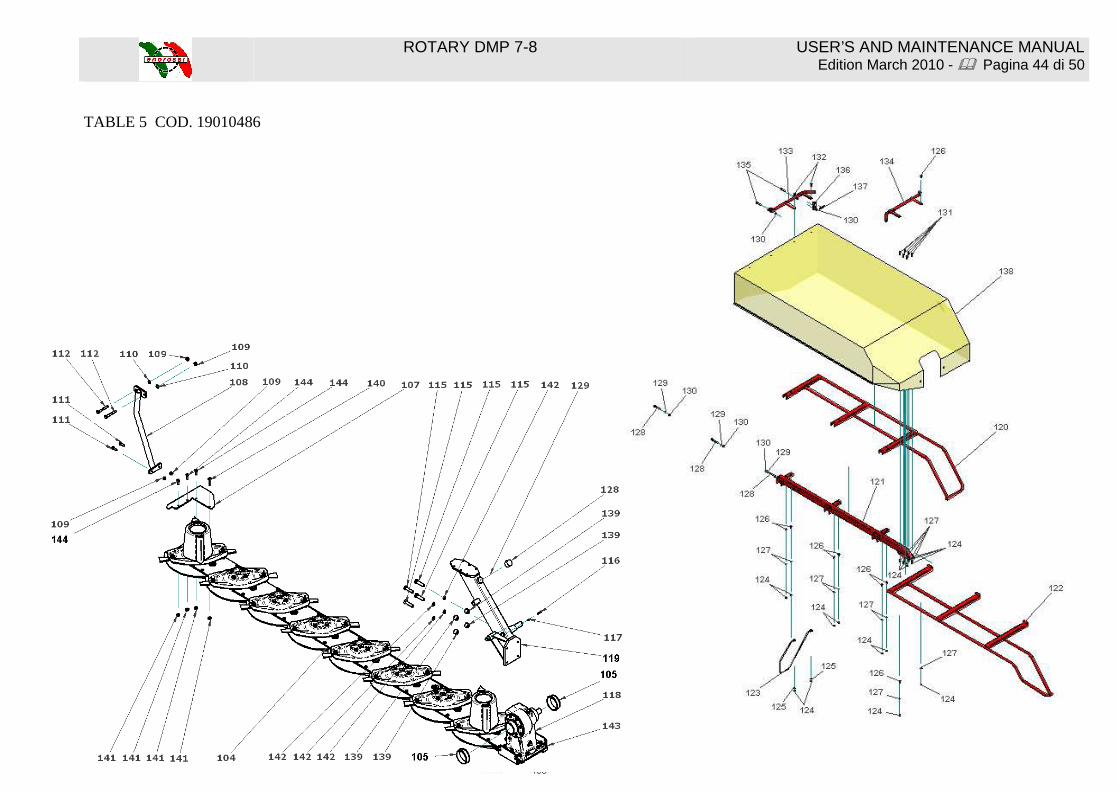
TABLE 5 COD. 19010486

ROTARY DMP 7-8 USER’S AND MAINTENANCE MANUAL Edition March 2010 - � Pagina 45 di 50
TABLE 5 COD. 19010486 Pos. Code Description Qty. Pos. Code Description Qty. Pos. Code Description Qty.
103 18031937 Mobile support 1 117 3080109 Spring pin 6x32 1 129 3030162 Washer M12 3
104 12660316 Rubber knob 1 118 18032432 Gear box 1 130 3020202 Self locking nut M12 5
105 12240199 Sliding bearing 2 119 3011206 Screw T.E. M10x30 4 131 3011624 Screw T.E. M10x35 6
106 12880978 Cutter bar 1 120 18031940 Back protection DM 6P 1 132 3010128 Screw T.T.Q.S.T. M10x35
2
106/A 12881267 Cutter bar (DM 6P 3 knifes)
1 120/A 18031941 Back protection DM 7P 1 133 18031950 Back handle 1
106/B 12880981 Cutter bar (DM 7P 2 knifes)
1 120/B 18031942 Back protection DM 8P 1 134 18031951 Front handle 1
106/C 12880982 Cutter bar (DM 8P 2 knifes)
1 121 18031943 Protection bar DM 6P 1 135 3011207 Screw T.E. M12x60 2
106/D 12881268 Cutter bar DM 8P (3 knifes)
1 121/A 18031944 Protection bar DM 7P 1 136 18031952 Linkage plate 1
107 18031938 External skid 1 121/B 18031945 Protection bar DM 8P 1 137 11010515 Spring 1
108 18032427 Rod 1 122 18031946 Front protection DM 6P 1 138 9130010 Protection cover DM 6P
1
109 3020201 Self locking nut M10 4 122/A 18031947 Front protection DM 7P 1 138/A 9130012 Protection cover DM 7P
1
110 3030115 Washer M10 8 122/B 18031948 Front protection DM 8P 1 138/B 9130013 Protection cover DM 8P
1
111 3011206 Screw T.E. M10x30 2 123 18031949 Stem 1 139 18032429 Screw godronata M10x30
1
112 3011655 Screw T.E. M12x90 2 124 3020201 Self locking nut M10 16 140 18032431 Screw godronata M 10x50
1
113 3020201 Self locking nut M10 4 125 3030169 Washer M10 2
114 3020238 4 126 3010105 Screw T.T.Q.S.T. M10x25
8
115 3011644 4 127 3030159 Washer M10 14
116 3080113 Spring pin 6x50 1 128 3011214 Screw T.E. M12x100 3

ROTARY DMP 7-8 USER’S AND MAINTENANCE MANUAL Edition March 2010 - � Pagina 46 di 50
TABLE 6 COD. 19010492

ROTARY DMP 7-8 USER’S AND MAINTENANCE MANUAL Edition March 2010 - � Pagina 47 di 50
TABLE 6 COD.19010492 Pos. Type Code Description Pos. Type Code Description Pos. Type Code Description
3 1012565 Deflector support 23 DM4-5-6
3011241 Screw T.E. M12x30 35/C DM7 12580041 Reinforcement
7 12580023 Cover 23/A DM6-7-8
3011216 Screw T.E. M12x35 35/D DM8 12580042 Reinforcement
8 12580024 Disc convey (2 blades) 24 3030162 Washer M12 36 DM4/6/8
12580043 Skid
9 3011268 Screw M12x20 25 12580030 Reinforcement 36A DM5/7 18032441 Skid
10 3030162 Washer M12 26 18031990 Box support 37 12580045 Skid
11 3020233 Self locking nut M12 27 3030159 Washer M10 38 DM4 12580046 Lower support
13 12881278 Disc (2 blades) 28 3020201 Self locking nut M10 38/A DM5 12580047 Lower support
14 12881271 Right blade 29 3010105 Screw TTQST M10x25 38/B DM6 12580048 Lower support
15 12881270 Left blade 30 12580032 Disc (3 blades) 38/C DM7 12580049 Lower support
16 12881272 Pin knife support 31 3011644 Screw M12x60 38/D DM8 12580050 Lower support
17 DM4 12580025 Upper support 32 12881273 Disc convey (3 blades) 39 12580051 Special screw M10x28
17/A DM5 12580026 Upper support 33 3010407 Screw M12x70 39/A 12580052 Special screw M10x38
17/B DM6 12580027 Upper support 34 DM4 12580033 Reinforcement 39/B 12580053 Special screw M10x50
17/C DM7 12580028 Upper support 34/A DM5 12580034 Reinforcement 40 3020708 Nut M10
17/D DM8 12580029 Upper support 34/B DM6 12580035 Reinforcement 41 12580054 Bushing
18 4010822 Plug 3/8 34/C DM7 12580036 Reinforcement 42 3020708 Nut M10
19 18031987 Box support 34/D DM8 12580037 Reinforcement 43 18032439 Cover support
20 18031988 Internal deflector 35 DM4 12580038 Reinforcement 44 3030403 Copper washer 3/8
21 3020202 Self locking nut M12 35/A DM5 12580039 Reinforcement 45 4010832 Plug 3/8 22 3011213 Screw T.E. M12x45 35/B DM6 12580040 Reinforcement 46 10010704 Oring
ROTARY DMP 7-8 USER’S AND MAINTENANCE MANUAL Edition March 2010 - � Pagina 48 di 50
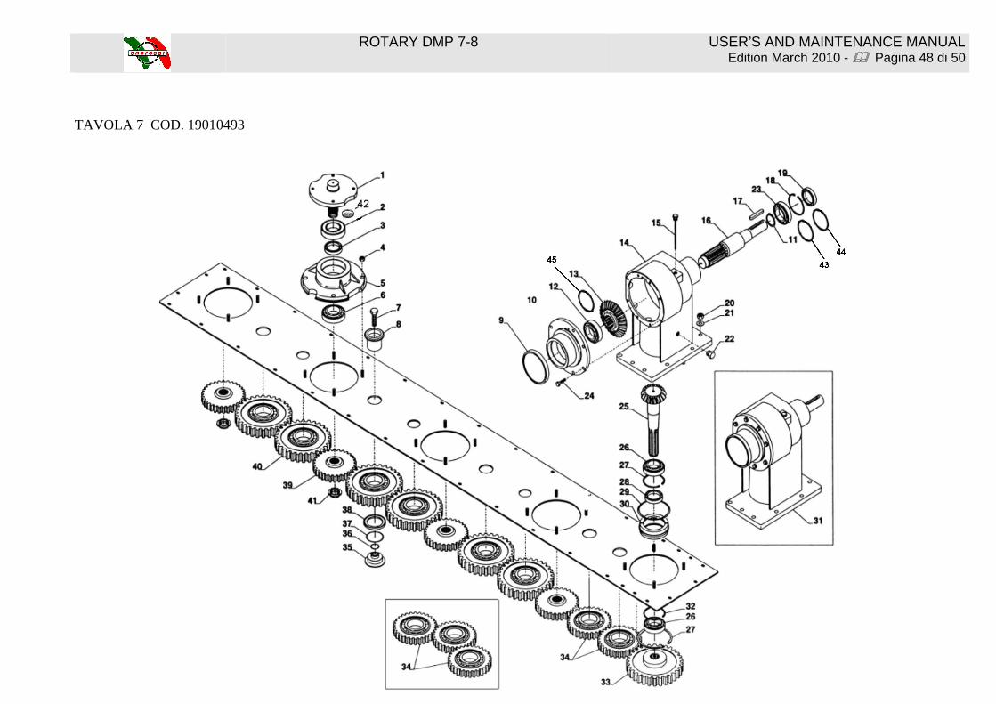
TAVOLA 7 COD. 19010493
ROTARY DMP 7-8 USER’S AND MAINTENANCE MANUAL Edition March 2010 - � Pagina 49 di 50
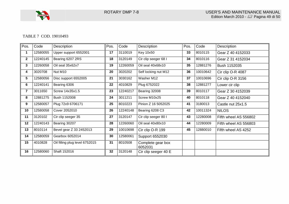
TABLE 7 COD. 19010493 Pos. Code Description Pos. Code Description Pos. Code Description
1 12580055 Upper support 6552001 17 3110019 Key 10x50 33 8010115 Gear Z 40 4152033
2 12240145 Bearing 6207 2RS 18 3120149 Cir clip seeger 68 I 34 8010116 Gear Z 31 4152034
3 12260058 Oil seal 35x62x7 19 12260059 Oil seal 40x68x10 35 12881276 Bush 1152035
4 3020708 Nut M10 20 3020202 Self locking nut M12 36 10010642 Cir clip O-R 4087
5 12580056 Disc support 6552005 21 3030162 Washer M12 37 10010696 Cir clip O-R 3156
6 12240141 Bearing 6306 22 4010829 Plug 6752022 38 12881277 Lower cir clip
7 3011650 Screw 14x35x1.5 23 12240217 Bearing 32008 39 8010117 Gear Z 30 4152039
8 12881275 Bush 1152008 24 3011211 Screw M10x25 40 8010118 Gear Z 40 4152040
9 12580057 Plug 72x9 6706171 25 8010223 Pinion Z 16 5052025 41 3180013 Castle nut 25x1.5
10 12580058 Cover 2052010 26 12240148 Bearing 6208 C3 42 10011324 NILOS
11 3120102 Cir clip seeger 35 27 3120147 Cir clip seeger 80 I 43 12280008 Fifth wheel AS 556802
12 12240143 Bearing 30207 28 12260060 Oil seal 40x80x10 44 12280009 Fifth wheel AS 556803
13 8010114 Bevel gear Z 33 2452013 29 10010698 Cir clip O-R 199 45 12880010 Fifth wheel AS 4252
14 12580059 Gearbox 6052014 30 12580061 Support 6552030
15 4010828 Oil filling plug level 6752015 31 8010508 Complete gear box 6052031
16 12580060 Shaft 152016 32 3120148 Cir clip seeger 40 E

ROTARY DMP 7-8 USER’S AND MAINTENANCE MANUAL Edition March 2010 - � Pagina 50 di 50
Related Documents