M DET2/2 Digital Earth Tester USER GUIDE GUIDE DE L’UTILISATEUR GEBRAUCHSANLEITUNG GUÍA DEL USUARIO

Welcome message from author
This document is posted to help you gain knowledge. Please leave a comment to let me know what you think about it! Share it to your friends and learn new things together.
Transcript

M
DET2/2Digital Earth Tester
USER GUIDE
GUIDE DE L’UTILISATEUR
GEBRAUCHSANLEITUNG
GUÍA DEL USUARIO

2
SAFETY WARNINGS
• Special precautions are necessary when ‘live’ earths may be encountered, and isolation switches and fusesare needed in this situation. See ‘Operation - Earth Testing Safety Precautions’.
• The earth spikes, test leads and their terminations must not be touched while the instrument is switched ‘On’.
• When working near high tension systems, rubber gloves and shoes should be worn.
• The DET2/2 must be disconnected from any external circuit while its battery cells are being charged.
• A 12 V d.c. battery must not be used as an external supply while it is still connected to the vehicle.
• Replacement fuses must be of the correct type and rating
• Before charging the DET2/2 battery ensure that the correct supply fuse is fitted and the voltage selector isset correctly.
• Warnings and precautions must be read and understood before the instrument is used. They must beobserved during use.
NOTE
THE INSTRUMENT MUST ONLY BE USED BY SUITABLY TRAINED AND COMPETENT PERSONS.
Safety Warnings 2
Contents 3General Description 4Applications 5Features and Controls 6Initial Configuration 7Setting up Test spikes 8
Earth Testing Safety Precautions 9
OperationGeneral Testing Procedure 11Test condition adjustments 11Display messages 12Error messages 13Battery charging 15
Measuring TechniquesTesting earth electrodes
Fall-of-Potential method 17The 61,8% Rule 18The Slope method 20Method using ‘Dead’ earth 22BS7671 (16th Edition IEE Wiring Regulations) Requirements 23Other methods 23Determining ‘Touch’ potential 24Determining ‘Step’ potential 25
Measuring soil resistivity -Typical variations in soil resistivity 26Line traverse 27Calculation of Resistivity 27
Continuity Testing 29Specification 30Accessories 33Chart for use with Slope method 35Repair and Warranty 40
Guide de l’utilisateur 43
Gebrauchsanleitung 67
Guía del Usuario 90
Symbols used on the instrument
Caution: Refer to accompanying notes.
Equipment protected throughout by Double Insulation (Class II)
Equipment complies with EU Directives
Contents Guide de l’utilisateur p43 Gebrauchsanleitung s67 Guía del usuario p91
3
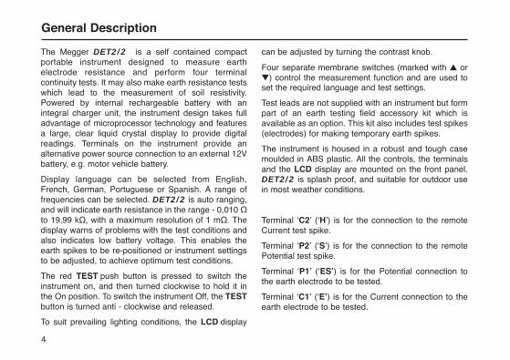
The Megger DET2/2 is a self contained compactportable instrument designed to measure earthelectrode resistance and perform four terminalcontinuity tests. It may also make earth resistance testswhich lead to the measurement of soil resistivity.Powered by internal rechargeable battery with anintegral charger unit, the instrument design takes fulladvantage of microprocessor technology and featuresa large, clear liquid crystal display to provide digitalreadings. Terminals on the instrument provide analternative power source connection to an external 12Vbattery, e.g. motor vehicle battery.
Display language can be selected from English,French, German, Portuguese or Spanish. A range offrequencies can be selected. DET2/2 is auto ranging,and will indicate earth resistance in the range - 0,010 Ωto 19,99 kΩ, with a maximum resolution of 1 mΩ. Thedisplay warns of problems with the test conditions andalso indicates low battery voltage. This enables theearth spikes to be re-positioned or instrument settingsto be adjusted, to achieve optimum test conditions.
The red TEST push button is pressed to switch theinstrument on, and then turned clockwise to hold it inthe On position. To switch the instrument Off, the TESTbutton is turned anti - clockwise and released.
To suit prevailing lighting conditions, the LCD display
can be adjusted by turning the contrast knob.
Four separate membrane switches (marked with ▲ or▼) control the measurement function and are used toset the required language and test settings.
Test leads are not supplied with an instrument but formpart of an earth testing field accessory kit which isavailable as an option. This kit also includes test spikes(electrodes) for making temporary earth spikes.
The instrument is housed in a robust and tough casemoulded in ABS plastic. All the controls, the terminalsand the LCD display are mounted on the front panel.DET2/2 is splash proof, and suitable for outdoor usein most weather conditions.
Terminal ‘C2’ (‘H’) is for the connection to the remoteCurrent test spike.
Terminal ‘P2’ (‘S’) is for the connection to the remotePotential test spike.
Terminal ‘P1’ (‘ES’) is for the Potential connection tothe earth electrode to be tested.
Terminal ‘C1’ (‘E’) is for the Current connection to theearth electrode to be tested.
General Description
4
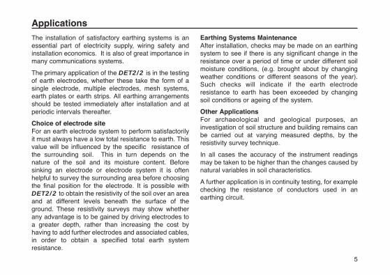
The installation of satisfactory earthing systems is anessential part of electricity supply, wiring safety andinstallation economics. It is also of great importance inmany communications systems.
The primary application of the DET2/2 is in the testingof earth electrodes, whether these take the form of asingle electrode, multiple electrodes, mesh systems,earth plates or earth strips. All earthing arrangementsshould be tested immediately after installation and atperiodic intervals thereafter.
Choice of electrode siteFor an earth electrode system to perform satisfactorilyit must always have a low total resistance to earth. Thisvalue will be influenced by the specific resistance ofthe surrounding soil. This in turn depends on thenature of the soil and its moisture content. Beforesinking an electrode or electrode system it is oftenhelpful to survey the surrounding area before choosingthe final position for the electrode. It is possible withDET2/2 to obtain the resistivity of the soil over an areaand at different levels beneath the surface of theground. These resistivity surveys may show whetherany advantage is to be gained by driving electrodes toa greater depth, rather than increasing the cost byhaving to add further electrodes and associated cables,in order to obtain a specified total earth systemresistance.
Earthing Systems MaintenanceAfter installation, checks may be made on an earthingsystem to see if there is any significant change in theresistance over a period of time or under different soilmoisture conditions, (e.g. brought about by changingweather conditions or different seasons of the year).Such checks will indicate if the earth electroderesistance to earth has been exceeded by changingsoil conditions or ageing of the system.
Other ApplicationsFor archaeological and geological purposes, aninvestigation of soil structure and building remains canbe carried out at varying measured depths, by theresistivity survey technique.
In all cases the accuracy of the instrument readingsmay be taken to be higher than the changes caused bynatural variables in soil characteristics.
A further application is in continuity testing, for examplechecking the resistance of conductors used in anearthing circuit.
Applications
5

6
Features and Controls
To electrode under test(Potential connection)
To electrode under test(Current connection)
Charger socket
External 12 V d.c.supply Terminals
Display contrastadjustment
To Potential test spikeTo Current test spike
On / Off Test Button
(Rotate clockwise to lock)
31⁄2 digit L.C.D.
Test control switches
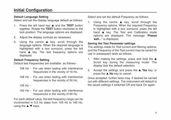
Default Language SettingSelect and set the display language default as follows:
1. Press the left hand key ▲ and the TEST button together. Rotate the TEST button clockwise to thelock position. The language options are displayed.
2. Adjust the display contrast as necessary.
3. Using the centre ▲ key, scroll through the language options. When the required language is highlighted with a box surround, press the left hand ▲ key. The test frequency options are displayed.
Default Frequency SettingDefault test frequencies are available as follows:-
108 Hz - For use when testing with interference frequencies in the vicinity of 16 Hz.
128 Hz - For use when testing with interference frequencies in the vicinity of 50 Hz.
135 Hz -
150 Hz - For use when testing with interference frequencies in the vicinity of 60 Hz.
For each default value, the test frequency range can beincremented in 0,5 Hz steps from 105 Hz to 160 Hz;using the ▲ ▼ keys.
Select and set the default Frequency as follows:
1. Using the centre ▲ key, scroll through the Frequency options. When the required Frequency is highlighted with a box surround, press the left hand ▲ key. The Test and Calibration mode options are displayed. The message “Please wait...” is displayed.
Saving the Test Parameter settingsThe settings made for Test current and filtering options,and the Frequency of the Test current may be saved foruse in subsequent tests as follows:
1. After making the settings, press and hold the ▲
Scroll key during the measuring mode. The display lists the default selection.
2. Accept the settings and press the ▲ Yes key, or press the ▲ No key to cancel.
Once accepted, further tests may, if desired be carriedout with different settings. The instrument will default tothe saved settings if switched Off and back On again.
Initial Configuration
7

For earth electrode testing and for earth resistivitysurveying, the instrument’s test leads are connected tospikes inserted in the ground. The way the connectionsare made depends on the type of test being undertakenand details are given in ‘Measuring Techniques’.
Test spikes and long test leads are necessary for alltypes of earth testing and the optional earth testing fieldaccessory kits contain the basic equipment. See‘Accessories’.
1. Insert the Current test spike into the ground 30 to 50 metres away from the Earth electrode to to be tested.
2. Connect this spike to the instrument terminal 'C2' (‘H’).
3. Insert the Potential test spike into the ground midway between the Current test spike and the Earth electrode, and in direct line with them both.
4. Connect this spike to the instrument terminal 'P2' (‘S’).
5. When running the test leads out to each remote electrode, avoid laying the wires too close to each other.
Setting up the Test spikes
8
9
Electrode Isolation or DuplicationIt is preferable that the earth electrode to be tested isfirst isolated from the circuit it is protecting, so that onlythe earth is measured and not the complete system.When this is done, the circuits and equipment must bede-energised. If however this is not possible, the earthelectrode should be duplicated, so that when it isdisconnected for test purposes, the other one providesthe necessary circuit protection.
‘Live’ earth safety precautionsThe DET2/2 allows earth testing to be done at arelatively safe voltage using a maximum of a 50 V RMSsquare wave at a frequency of nominally 128 Hz. In useit is normally connected only to electrodes which are atearth potential.
A 'Live' earth is one that carries current from the mainssupply, or could do so under fault conditions.
When working around power stations or sub stationsthere is a danger that large potential gradients willoccur across the ground in the event of a phase to earthfault. A wire which is connected to ground many metresaway will then no longer be at the same potential aslocal ground, and in some cases could rise to above 1 kV. The following safety precautions are essential.
1. All persons involved must be trained and competent in isolation and safety procedures for
the system to be worked on. They must be clearly instructed not to touch the earth electrode; test spikes; test leads, or their terminations if any 'Live' earths may be encountered. It is recommended that persons involved wear appropriate rubber gloves, rubber soled shoes, and stand on rubber mats.
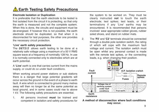
2. The 'P2' and 'C2' terminals should be connected through a double pole isolation switch, the rating of which will cope with the maximum fault voltage and current. The isolation switch must be open whilst any personal contact is made with the remote test spikes, or the connecting leads, e.g. when changing their position.
A method of disconnection where fault conditionsmay occur.
Earth Testing Safety Precautions
������������������������������������Earth
resistance
D.P. Isolation switch
True earth
Fuses
Remotespikes
Voltage rise ofearthing system
under faultconditions
Faultcurrent
Earth Testing Safety Precautions
10
If isolation switches cannot be used, the leads shouldbe disconnected from the instrument before remotespikes and leads are handled. When the remoteconnections have been made, the final connectionsshould be made to the instrument using insulatedplugs, ensuring that the Operator takes adequate andappropriate precautions such as insulating mats,rubber gloves etc.
If a fault occurs while a test is being made theinstrument may be damaged. Incorporating fuses(rated at 100 mA and able to cope with the maximumfault voltage) at the isolation switch will provide someprotection for the instrument.
Caution: When working on live sites, do not use anexternal battery to power the instrument, as this wouldalso become live under fault conditions.
11
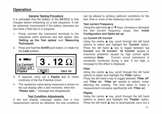
General Testing ProcedureIt is advisable that the battery of the DET2/2 is fullycharged before embarking on a test sequence. It canbe extremely inconvenient if the battery becomes toolow while a field test is in progress.
1. Firmly connect the instrument terminals to the respective earth electrode and test spikes. See ‘Setting up the Test spikes‘ and ‘Measuring Techniques‘.
2. Press and hold the On/Off push button, or rotate it to the Lock position.
3. If required, carry out a Pspike test to check continuity of the the Potential circuit.
4. The resistance value being measured is shown on the sub display after a few moments, when the “Please wait...” message has disappeared.
Test Condition AdjustmentsIf the sub display message states that a truemeasurement cannot be obtained, the test conditions
can be altered to achieve optimum conditions for thetest. One or more of the following may be used:-
Test current FrequencyUsing the right hand ▲ or ▼ keys, increase or decreasethe test current frequency range. See ‘InitialConfiguration and Spike set up‘.
Lo Current /Hi CurrentUsing the centre ▲ key, scroll through the left handoptions to select and highlight the ‘Current‘ option.Press the left hand ▲ key to toggle between ‘LoCurrent‘ and ‘Hi Current‘. ‘Hi Current‘ assists toovercome problems caused by high current spikeresistance. Note: Current circuit resistance isconstantly monitored during a test. If too high, amessage to this effect is displayed.
FilterUsing the centre ▲ key, scroll through the left handoptions to select and highlight the ‘Filter‘ option.Press the left hand s key to toggle between ‘Filter off‘and ‘Filter on‘. ‘Filter on‘ assists to reduce ‘noise‘affecting the reading. The time taken to make ameasurement increases significantly with ‘Filter on‘.
PSpikeUsing the centre ▲ key, scroll through the left handoptions to select and highlight the ‘Pspike‘ option.Press the left hand ▲ key to automatically carry out a
Operation
resistance check of the of the Potential circuit. After ashort pause, the result of this check is displayed on thesub panel. If appropriate, the ‘Pspike‘ label thenchanges to ‘Retest’, giving the option to repeat the testafter any alteration to spike position etc. has beenmade. Press the centre ▲ key, now labelled ‘Measure’to repeat the measurement.
Note: If for any reason a test is made with an openPotential circuit, the resultant test reading will beinvalid. To confirm that connections are still in placeand to check the validity of the test, a ‘P spike‘ checkshould be made before each test.
Auto RangingIf the earth resistance being measured is low, but ahigh level of ’noise’ is present, coupled with a highCurrent spike resistance, the instrument willautomatically make a measurement with a lowerprecision. If successful, the resistance reading will bedisplayed with only 3 digits, the least significant digitbeing blanked out. Greater precision can be obtained by:-
a) Reducing spike resistance (e.g. by wetting the ground, or by inserting the spikes deeper into the ground).
b) Toggling to ‘Hi Current‘ option.
c) Eliminating the ‘noise’ source if possible.
Display MessagesWhen appropriate, messages are displayed. Thefollowing message definitions are given:
“Please wait...”“Please wait... zeroing”
This means that the instrument is making internalmeasurements and tests before displaying theresistance reading. The ▲ and ▼ keys remain activeand measurement conditions may be adjusted beforea reading is displayed. These messages may berepeatedly displayed if there is a high ‘noise’ levelpresent, close to the frequency of the measurement,or if the Potential circuit is incorrectly connected.
“Open Circuit Current Terminals”This means that the test current flowing is low, andimplies that a resistance of >500 kΩ is present betweenthe test terminals. If this message remains displayedwhen terminals ‘C1‘ and ‘C2‘ are shorted together, aninternal fuse has ruptured, with the possibility of otherinternal damage having been caused. In this case,return the instrument, return the instrument to themanufacturer or an approved repair company. See’Repair and Warranty’.
“Check connections voltage terminals”This message is displayed when the connections to the‘P1‘ and ‘P2‘ connections are reversed. Check and
correct as necessary.
Operation
12
“High current noise”“High voltage noise”
These messages are displayed when the noise voltagepresent is greater than the acceptable level, causingthe measurement to be invalid. Changing the testfrequency will have no effect in this instance. Ifpossible, eliminate the noise source, or reduce spikeresistance (e.g. by wetting the ground, or by insertingthe spikes deeper into the ground).
Further Display MessagesHigh level of interference or an instrument fault couldcause the display of any of the following messages:
“Invalid current”
“Invalid voltage”
“Invalid current zero”
“Invalid voltage zero”
“Current zero too big”
“Voltage zero too big”
“Noisy current zero”
“Noisy voltage zero”
Incorrect connection of the potential terminals couldcause an ‘Invalid voltage’ message.
Error MessagesError messages may appear on the bottom line of thedisplay in the event of a instrument or software fault, ordue to the existence of adverse electrical conditions. Ifan error message appears, switch the DET2/2 off,refer to ‘Repair and Warranty’ and return theinstrument to the manufacturer or approved agent,giving details of the error message and the softwareedition.
“Calibration data retrieval error
Refer to handbook”
If calibration data stored in the instrument has beenincorrectly retrieved, the above message is displayed(in English) when switching on. Switch the DET2/2off, refer to ’Repair and Warranty’ and return theinstrument to the manufacturer or approved agent,giving details of the error message and the softwareedition.
“Setup data retrieval error”
Default language, frequency and current level arenormally retrieved when the instrument is switched on.
If unsuccessful, the above message is displayed (inEnglish) when switching on, with the option to “Retry”(try reading the data again) or “Manual” (manually setup the data again). If ‘Retry’ or ‘Manual’ is
13

unsuccessful, switch the DET2/2 off, refer to ’Repairand Warranty’ and return the instrument to themanufacturer or approved agent, giving details of theerror message and the software edition.
Operation
14

15
Battery capacityThe capacity of the battery is continuously monitoredand displayed, adjacent to the battery symbol. Theindicator segments will show fully charged, or recedeas the battery is used, to indicate three quarters full,half full or quarter full. A warning message is displayedif the battery is unable to supply adequate test current.
Charging methodIt is advisable that the battery is fully charged beforeembarking on a test sequence. Charging is carried outby external a.c. mains supply only. Chargingcommences automatically as soon as the supply isconnected. Normal recharge time is 6 hours. Testing isinhibited during charging.
Battery charging requires a supply voltage of 100 V to130 V a.c., or 200 V to 260 V, 50 - 60 Hz. Connectionto a voltage from 130 V to 200 V will not cause harm,but will not charge the battery, and the message“Power Supply too low” will be displayed. Chargingtime will be extended if either the power supply voltagedrops too low during the charge period or if the batteryhas been excessively discharged. Charge the batteryas follows:
1. Switch the Test switch to Off.
2. Remove any connections to the 4 mm external supply sockets.
3. Disconnect and remove the test leads.
4. Connect the mains supply to the IEC 320 connector on the top right of the instrument. Confirm that the message “Charging On” is displayed. Progressive and accumulated charging times are displayed.
5. When fully charged, the charging current will automatically reduce to ”Trickle Charge“. Charging will automatically stop after a period of 24 hours.
Note: The battery will be prevented from charging if anexternal battery is connected to the 4 mm socketsduring the charging process. An external connectedbattery cannot be charged via the instrument.
Battery Charging

Battery Charging Power cord plugIf the power cord plug is not suitable for your type ofsocket, do not use an adaptor. You should use asuitable alternative power cord, or if necessary, changethe plug by cutting the disconnected cord and fitting asuitable plug.
The colour code of the cord is:-
Earth (Ground) - Yellow/Green
Neutral - Blue
Phase(Line) - Brown
If using a fused plug, a 3 amp fuse to BS 1362 shouldbe fitted.
Note: A plug severed from the power cord should bedestroyed, as a plug with bare connections ishazardous in a live socket outlet.
Battery Charging Notes
1) Do Not leave battery in a totally discharged state. If the instrument is idle for long periods, recharge the battery at least every 6 months. (More frequently if the storage temperature is >40 °C).
2) Battery charging should be carried out in a dry environment and at temperatures in the range 0 °C to 40°C.
3) When charging the battery indoors, the area should be well ventilated.
Battery Charging
16
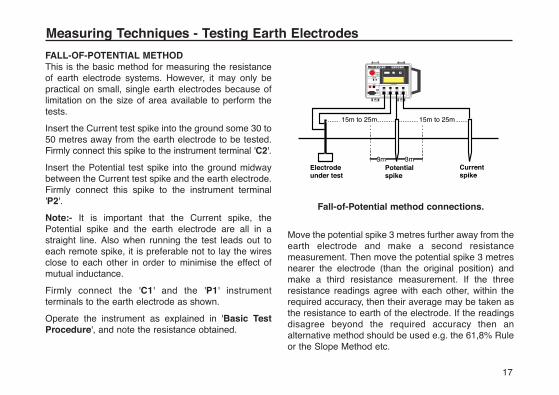
FALL-OF-POTENTIAL METHODThis is the basic method for measuring the resistanceof earth electrode systems. However, it may only bepractical on small, single earth electrodes because oflimitation on the size of area available to perform thetests.
Insert the Current test spike into the ground some 30 to50 metres away from the earth electrode to be tested.Firmly connect this spike to the instrument terminal 'C2'.
Insert the Potential test spike into the ground midwaybetween the Current test spike and the earth electrode.Firmly connect this spike to the instrument terminal'P2'.
Note:- It is important that the Current spike, thePotential spike and the earth electrode are all in astraight line. Also when running the test leads out toeach remote spike, it is preferable not to lay the wiresclose to each other in order to minimise the effect ofmutual inductance.
Firmly connect the 'C1' and the 'P1' instrumentterminals to the earth electrode as shown.
Operate the instrument as explained in 'Basic TestProcedure', and note the resistance obtained.
Fall-of-Potential method connections.
Move the potential spike 3 metres further away from theearth electrode and make a second resistancemeasurement. Then move the potential spike 3 metresnearer the electrode (than the original position) andmake a third resistance measurement. If the threeresistance readings agree with each other, within therequired accuracy, then their average may be taken asthe resistance to earth of the electrode. If the readingsdisagree beyond the required accuracy then analternative method should be used e.g. the 61,8% Ruleor the Slope Method etc.
17
Measuring Techniques - Testing Earth Electrodes
Electrode�under test
Potential �spike
3m 3m
15m to 25m 15m to 25m
�Current�spike
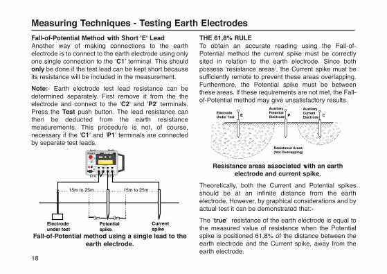
Fall-of-Potential Method with Short 'E' LeadAnother way of making connections to the earthelectrode is to connect to the earth electrode using onlyone single connection to the ‘C1’ terminal. This shouldonly be done if the test lead can be kept short becauseits resistance will be included in the measurement.
Note:- Earth electrode test lead resistance can bedetermined separately. First remove it from the theelectrode and connect to the 'C2' and 'P2' terminals.Press the Test push button. The lead resistance canthen be deducted from the earth resistancemeasurements. This procedure is not, of course,necessary if the 'C1' and 'P1' terminals are connectedby separate test leads.
Fall-of-Potential method using a single lead to theearth electrode.
THE 61,8% RULETo obtain an accurate reading using the Fall-of-Potential method the current spike must be correctlysited in relation to the earth electrode. Since bothpossess ‘resistance areas’, the Current spike must besufficiently remote to prevent these areas overlapping.Furthermore, the Potential spike must be betweenthese areas. If these requirements are not met, the Fall-of-Potential method may give unsatisfactory results.
Resistance areas associated with an earthelectrode and current spike.
Theoretically, both the Current and Potential spikesshould be at an infinite distance from the earthelectrode. However, by graphical considerations and byactual test it can be demonstrated that:-
The ‘true’ resistance of the earth electrode is equal tothe measured value of resistance when the Potentialspike is positioned 61,8% of the distance between theearth electrode and the Current spike, away from theearth electrode.
18
Measuring Techniques - Testing Earth Electrodes
����
��������
E P C
Auxiliary�Current�Electrode
Auxiliary�Potential�Electrode
Electrode�Under Test
Resistance Areas�(Not Overlapping)
Electrode�under test
Potential �spike
3m 3m
15m to 25m 15m to 25m
�Current�spike
19
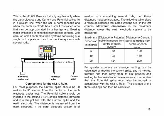
This is the 61,8% Rule and strictly applies only whenthe earth electrode and Current and Potential spikes liein a straight line, when the soil is homogeneous andwhen the earth electrode has a small resistance areathat can be approximated by a hemisphere. Bearingthese limitations in mind this method can be used, withcare, on small earth electrode systems consisting of asingle rod or plate etc. and on medium systems withseveral rods.
Connections for the 61,8% Rule.For most purposes the Current spike should be 30metres to 50 metres from the centre of the earthelectrode under test. The Potential spike should beinserted in the ground 61,8% of this distance, betweenand in a straight line with, the Current spike and theearth electrode. The distance is measured from theearth electrode. If the earth electrode system is of
medium size containing several rods, then thesedistances must be increased. The following table givesa range of distances that agree with the rule. In the firstcolumn ‘Maximum dimension’ is the maximumdistance across the earth electrode system to bemeasured.
For greater accuracy an average reading can becalculated by moving the current spike, say 10 metres,towards and then away from its first position andmaking further resistance measurements. (Rememberthat the Potential spike must also be moved inaccordance with the 61,8% Rule). The average of thethree readings can then be calculated.
Electrode�under test
Potential �spike
�Current�spike
61,8% of EC 38,2% of EC
Distance to Potentialspike in metres from
centre of earthsystem
Distance to Currentspike in metres from
centre of earthsystem
Maximum dimensionin metres
5
10
20
62
93
124
100
150
200
20
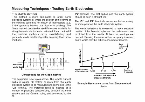
Measuring Techniques - Testing Earth ElectrodesTHE SLOPE METHODThis method is more applicable to larger earthelectrode systems or where the position of the centre ofthe earthing system is not known or inaccessible (e.g.if the system is beneath the floor of a building). TheSlope method can also be used if the area available forsiting the earth electrodes is restricted. It can be tried ifthe previous methods prove unsatisfactory andgenerally yields results of greater accuracy than thosemethods.
Connections for the Slope method
The equipment is set up as shown. The remote Currentspike is placed 50 metres or more from the earthelectrode system to be measured and connected to the'C2' terminal. The Potential spike is inserted at anumber of positions consecutively, between the earthsystem and the Current spike, and connected to the
'P2' terminal. The test spikes and the earth systemshould all be in a straight line.
The 'C1' and 'P1' terminals are connected separatelyto some point on the earth electrode system.
The earth resistance is measured at each separateposition of the Potential spike and the resistance curveis plotted from the results. At least six readings areneeded. Drawing the curve will show up any incorrectpoints which may be either rechecked or ignored.
Example Resistance curve from Slope methodtests.
��
�
P
CElectrode�under test
EC
Position of Electrode P�measured from E
Arbitrary position �of Earth electrode 0,2 EC 0,4 EC 0,6 EC Position of �
C electrode
Earth �resistance �curve
R3R2
R1
Res
ista
nce
21
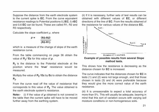
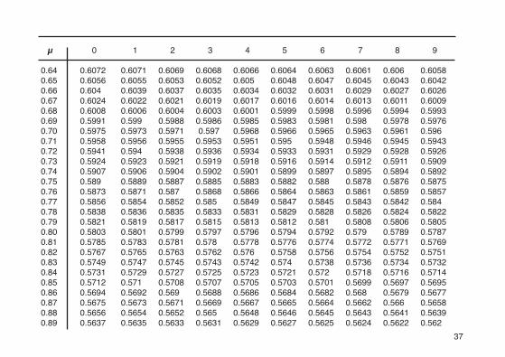
Suppose the distance from the earth electrode systemto the current spike is EC. From the curve equivalentresistance readings to Potential positions 0,2EC, 0,4ECand 0,6 EC can be found. These are called R1, R2 andR3 respectively.
Calculate the slope coefficient μ, where
μ = (R3-R2)
(R2-R1)
which is a measure of the change of slope of the earthresistance curve.
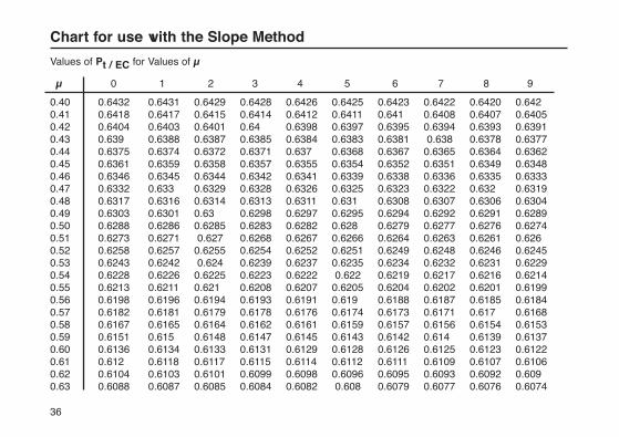
From the table commencing on page 36 obtain thevalue of Pt / Ec for this value of μ.
Pt is the distance to the Potential electrode at theposition where the ‘true’ resistance would bemeasured.
Multiply the value of Pt / Ec by Ec to obtain the distancePt.
From the curve read off the value of resistance thatcorresponds to this value of Pt. The value obtained isthe earth electrode system's resistance.
Note:- (i) If the value of μ obtained is not covered inthe table then the current spike will have to be movedfurther away from the earthing system.
(ii) If it is necessary, further sets of test results can beobtained with different values of EC, or differentdirections of the line of EC. From the results obtained ofthe resistance for various values of the distance EC.
Example of possible results from several Slopemethod tests.
This shows how the resistance is decreasing as thedistance chosen for EC is increased.
The curve indicates that the distances chosen for EC intests (1) and (2) were not large enough, and that thosechosen in tests (3) and (4) were preferable becausethey would give the more correct value of the earthresistance.
(iii) It is unreasonable to expect a total accuracy ofmore than 5%. This will usually be adequate, bearing inmind that this sort of variation occurs with varying soilmoisture conditions or non-homogeneous soils.
22
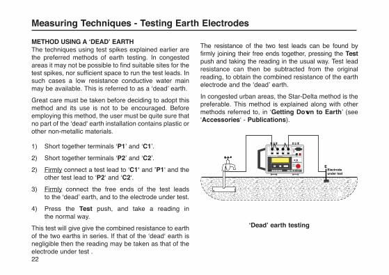
METHOD USING A ‘DEAD’ EARTH The techniques using test spikes explained earlier arethe preferred methods of earth testing. In congestedareas it may not be possible to find suitable sites for thetest spikes, nor sufficient space to run the test leads. Insuch cases a low resistance conductive water mainmay be available. This is referred to as a ‘dead’ earth.
Great care must be taken before deciding to adopt thismethod and its use is not to be encouraged. Beforeemploying this method, the user must be quite sure thatno part of the ‘dead‘ earth installation contains plastic orother non-metallic materials.
1) Short together terminals ‘P1’ and ‘C1’.
2) Short together terminals ‘P2’ and ‘C2’.
2) Firmly connect a test lead to ‘C1‘ and ’P1‘ and the other test lead to ‘P2‘ and ‘C2‘.
3) Firmly connect the free ends of the test leads to the ‘dead’ earth, and to the electrode under test.
4) Press the Test push, and take a reading in the normal way.
This test will give give the combined resistance to earthof the two earths in series. If that of the ‘dead‘ earth isnegligible then the reading may be taken as that of theelectrode under test .
The resistance of the two test leads can be found byfirmly joining their free ends together, pressing the Testpush and taking the reading in the usual way. Test leadresistance can then be subtracted from the originalreading, to obtain the combined resistance of the earthelectrode and the ‘dead’ earth.
In congested urban areas, the Star-Delta method is thepreferable. This method is explained along with othermethods referred to, in ‘Getting Down to Earth’ (see‘Accessories‘ - Publications).
‘Dead’ earth testing
Measuring Techniques - Testing Earth Electrodes
��������������������������������������
EElectrode�under test
23
6m 6m
EP C
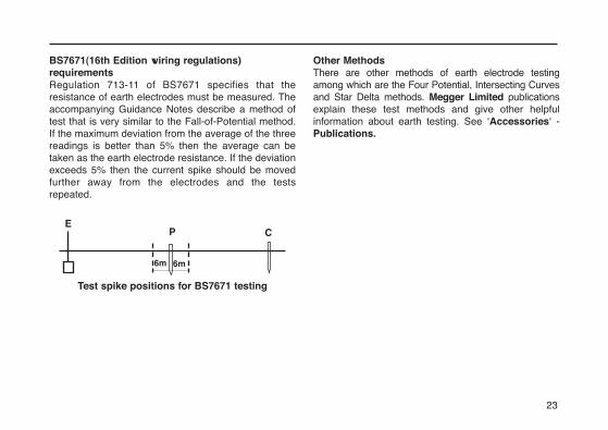
BS7671(16th Edition wiring regulations)requirementsRegulation 713-11 of BS7671 specifies that theresistance of earth electrodes must be measured. Theaccompanying Guidance Notes describe a method oftest that is very similar to the Fall-of-Potential method.If the maximum deviation from the average of the threereadings is better than 5% then the average can betaken as the earth electrode resistance. If the deviationexceeds 5% then the current spike should be movedfurther away from the electrodes and the testsrepeated.
Test spike positions for BS7671 testing
Other MethodsThere are other methods of earth electrode testingamong which are the Four Potential, Intersecting Curvesand Star Delta methods. Megger Limited publicationsexplain these test methods and give other helpfulinformation about earth testing. See ‘Accessories‘ -Publications.
24
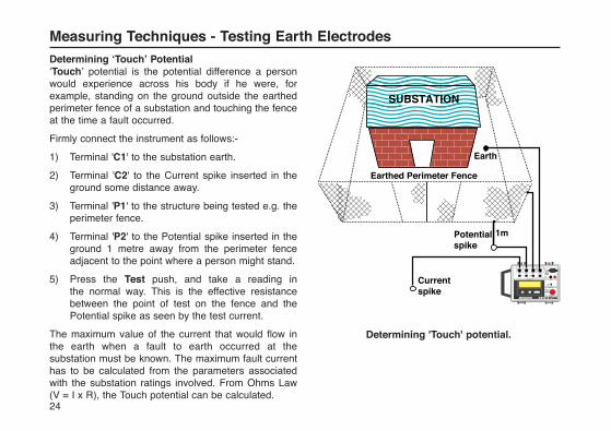
Determining ‘Touch’ Potential‘Touch’ potential is the potential difference a personwould experience across his body if he were, forexample, standing on the ground outside the earthedperimeter fence of a substation and touching the fenceat the time a fault occurred.
Firmly connect the instrument as follows:-
1) Terminal 'C1' to the substation earth.
2) Terminal 'C2' to the Current spike inserted in the ground some distance away.
3) Terminal 'P1' to the structure being tested e.g. the perimeter fence.
4) Terminal 'P2' to the Potential spike inserted in the ground 1 metre away from the perimeter fence adjacent to the point where a person might stand.
5) Press the Test push, and take a reading in the normal way. This is the effective resistance between the point of test on the fence and the Potential spike as seen by the test current.
The maximum value of the current that would flow inthe earth when a fault to earth occurred at thesubstation must be known. The maximum fault currenthas to be calculated from the parameters associatedwith the substation ratings involved. From Ohms Law(V = I x R), the Touch potential can be calculated.
Determining 'Touch' potential.
Measuring Techniques - Testing Earth Electrodes
�
������
�����
Earth���1m
�
Potential �spike
Current�spike
����
Earthed Perimeter Fence
SUBSTATION
25
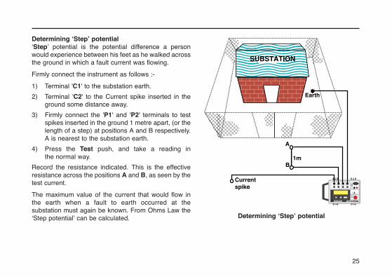
Determining ‘Step’ potential‘Step’ potential is the potential difference a personwould experience between his feet as he walked acrossthe ground in which a fault current was flowing.
Firmly connect the instrument as follows :-
1) Terminal 'C1' to the substation earth.
2) Terminal 'C2' to the Current spike inserted in the ground some distance away.
3) Firmly connect the 'P1' and 'P2' terminals to test spikes inserted in the ground 1 metre apart, (or the length of a step) at positions A and B respectively. A is nearest to the substation earth.
4) Press the Test push, and take a reading in the normal way.
Record the resistance indicated. This is the effectiveresistance across the positions A and B, as seen by thetest current.
The maximum value of the current that would flow inthe earth when a fault to earth occurred at thesubstation must again be known. From Ohms Law the‘Step potential’ can be calculated. Determining ‘Step’ potential
�
������
�����
Earth����
Current�spike
����
SUBSTATION
1m
A
B
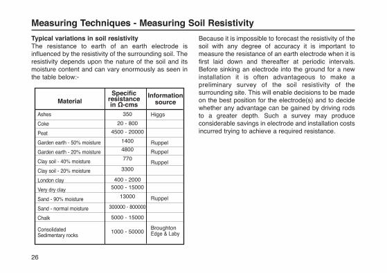
Typical variations in soil resistivityThe resistance to earth of an earth electrode isinfluenced by the resistivity of the surrounding soil. Theresistivity depends upon the nature of the soil and itsmoisture content and can vary enormously as seen inthe table below:-
Because it is impossible to forecast the resistivity of thesoil with any degree of accuracy it is important tomeasure the resistance of an earth electrode when it isfirst laid down and thereafter at periodic intervals.Before sinking an electrode into the ground for a newinstallation it is often advantageous to make apreliminary survey of the soil resistivity of thesurrounding site. This will enable decisions to be madeon the best position for the electrode(s) and to decidewhether any advantage can be gained by driving rodsto a greater depth. Such a survey may produceconsiderable savings in electrode and installation costsincurred trying to achieve a required resistance.
26
Measuring Techniques - Measuring Soil Resistivity
MaterialSpecific
resistancein Ω-cms
Information source
Ashes
Coke
Peat
Garden earth - 50% moisture
Garden earth - 20% moisture
Clay soil - 40% moisture
Clay soil - 20% moisture
London clay
Very dry clay
Sand - 90% moisture
Sand - normal moisture
Chalk
ConsolidatedSedimentary rocks
350
20 - 800
4500 - 20000
1400
4800
770
3300
400 - 20005000 - 15000
13000
300000 - 800000
5000 - 15000
1000 - 50000
Higgs
Ruppel
Ruppel
Ruppel
Ruppel
BroughtonEdge & Laby
27
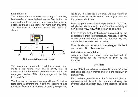
Line TraverseThe most common method of measuring soil resistivityis often referred to as the line traverse. Four test spikesare inserted into the ground in a straight line at equaldistances 'a' and to a depth of not more than 1/20 of 'a'.The instrument is connected to the test spikes asshown.
Soil resistivity measurement.
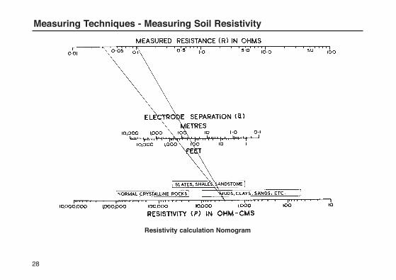
The instrument is operated and the measurementmade in the normal way. The resistivity may becalculated from the formula given opposite or from thenomogram overleaf. This is the average soil resistivityto a depth 'a'.
The four test spikes are then re-positioned for furthertests along a different line. If both the spacing 'a' andthe depth a/20 are maintained, a directly comparable
reading will be obtained each time, and thus regions oflowest resistivity can be located over a given area (atthe constant depth 'a').
Re-spacing the test spikes at separations 'b', 'c', 'd', etcwill yield results from which a profile of the resistivity atnew depths b/20, c/20, d/20,etc.can be obtained.
If the same line for the test spikes is maintained, but theseparation of them is progressively widened, resistivityvalues at various depths can be obtained. By thismeans depth surveys may be made.
More details can be found in the Megger Limitedpublications. See ‘Accessories‘.
Calculation of resistivityAssuming that the tests were carried out inhomogeneous soil the resistivity is given by theformula:-
ρ = 2πaR
where ‘R’ is the resistance measured in ohms, ‘a’ is thetest spike spacing in metres and ‘ρ’ is the resistivity inohm-metres.
For non-homogeneous soils the formula will give anapparent resistivity which is very approximately theaverage value to a depth equal to the test spike spacing'a'.
�
aa a
�C1 P1 P2 C2
a20
28
Resistivity calculation Nomogram
Measuring Techniques - Measuring Soil Resistivity
29
Measuring Techniques - Continuity Testing
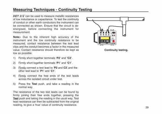
DET 2/2 can be used to measure metallic resistancesof low inductance or capacitance. To test the continuityof conduit or other earth conductors the instrument canbe connected as shown. Ensure that the circuit is de-energised, before connecting the instrument formeasurement.
Note:- Due to the inherent high accuracy of theinstrument and the low continuity resistance to bemeasured, contact resistance between the test leadclips and the conduit becomes a factor in the measuredvalue. Contact resistance should therefore be kept aslow as possible.
1) Firmly short together terminals ‘P2’ and ‘C2’.
2) Firmly short together terminals ‘P1’ and ‘C1’.
3) Firmly connect a test lead to ‘P2 and C2’,and the other test lead to ‘P1’ and ‘C1’.
4) Firmly connect the free ends of the test leads across the isolated circuit under test.
5) Press the Test push, and take a reading in the normal way.
The resistance of the two test leads can be found byfirmly joining their free ends together, pressing the Test push and taking the reading in the usual way. Testlead resistance can then be subtracted from the originalreading, to give a ‘true’ value of continuity resistance.
Continuity testing.
30
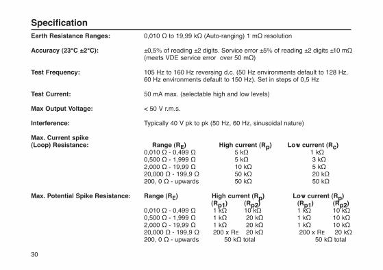
Earth Resistance Ranges: 0,010 Ω to 19,99 kΩ (Auto-ranging) 1 mΩ resolution
Accuracy (23°C ±2°C): ±0,5% of reading ±2 digits. Service error ±5% of reading ±2 digits ±10 mΩ(meets VDE service error over 50 mΩ)
Test Frequency: 105 Hz to 160 Hz reversing d.c. (50 Hz environments default to 128 Hz, 60 Hz environments default to 150 Hz). Set in steps of 0,5 Hz
Test Current: 50 mA max. (selectable high and low levels)
Max Output Voltage: < 50 V r.m.s.
Interference: Typically 40 V pk to pk (50 Hz, 60 Hz, sinusoidal nature)
Max. Current spike (Loop) Resistance: Range (RE) High current (Rp) Low current (Rc)
0,010 Ω - 0,499 Ω 5 kΩ 1 kΩ0,500 Ω - 1,999 Ω 5 kΩ 3 kΩ2,000 Ω - 19,99 Ω 10 kΩ 5 kΩ20,000 Ω - 199,9 Ω 50 kΩ 20 kΩ200, 0 Ω - upwards 50 kΩ 50 kΩ
Max. Potential Spike Resistance: Range (RE) High current (Rp) Low current (Rp)(Rp1) (Rp2) (Rp1) (Rp2)
0,010 Ω - 0,499 Ω 1 kΩ 10 kΩ 1 kΩ 10 kΩ0,500 Ω - 1,999 Ω 1 kΩ 20 kΩ 1 kΩ 10 kΩ2,000 Ω - 19,99 Ω 1 kΩ 20 kΩ 1 kΩ 10 kΩ20,000 Ω - 199,9 Ω 200 x RE 20 kΩ 200 x RE 20 kΩ200, 0 Ω - upwards 50 kΩ total 50 kΩ total
Specification

31
Display: Alpha numeric LCD (130 mm x 35 mm) giving test information and a large (20 mm) 31⁄2 digitLCD, maximum reading 1999
Instrument Protection: Meets the general requirements of IP54
Temperature Effect: <±0,1%/°C over the temperature range -10°C to +40°C
Temperature Range: Operating: -10°C to +40 °C Storage: -20°C to +60°C
Humidity: Operating: 90% RH max. at 40°C
Flash Test: 3 kV a.c.
Voltage Withstand: In the event of a system fault the instrument will withstand 240 V a.c. applied between any two terminals.
Compliance with Standards: BS 7430 (1992) BS7671 (1992) NFC 15 -100VDE 0413 Part 7 (1982) IEC364
Power Supply: (i) Internal rechargeable sealed lead acid cells 12 V nominal, 2,6 Ah capacity. Battery voltage range over which basic accuracy is maintained, 11,0 V to 13,5 V.
Battery life: Typically 5 Hours continuous use Battery charging time: 6 hours max. (from completely exhausted). Charging supply required: 100 V to 130 V or 200 V to 260 V a.c. 50 Hz/60 Hz.Power consumption: 25 VA
32
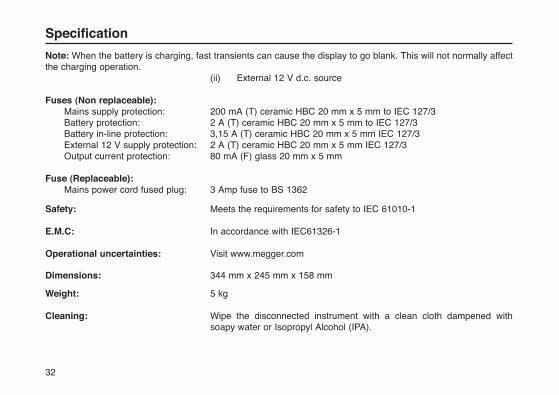
Note: When the battery is charging, fast transients can cause the display to go blank. This will not normally affectthe charging operation.
(ii) External 12 V d.c. source
Fuses (Non replaceable):Mains supply protection: 200 mA (T) ceramic HBC 20 mm x 5 mm to IEC 127/3 Battery protection: 2 A (T) ceramic HBC 20 mm x 5 mm to IEC 127/3 Battery in-line protection: 3,15 A (T) ceramic HBC 20 mm x 5 mm IEC 127/3 External 12 V supply protection: 2 A (T) ceramic HBC 20 mm x 5 mm IEC 127/3 Output current protection: 80 mA (F) glass 20 mm x 5 mm
Fuse (Replaceable):Mains power cord fused plug: 3 Amp fuse to BS 1362
Safety: Meets the requirements for safety to IEC 61010-1
E.M.C: In accordance with IEC61326-1
Operational uncertainties: Visit www.megger.com
Dimensions: 344 mm x 245 mm x 158 mm
Weight: 5 kg
Cleaning: Wipe the disconnected instrument with a clean cloth dampened with soapy water or Isopropyl Alcohol (IPA).
Specification
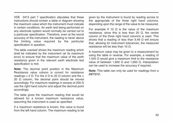
VDE 0413 part 7 specification stipulates that theseinstructions should contain a table or diagram showingthe maximum value which the instrument must indicatein certain conditions. An earth test being performed onany electrode system would normally be carried out toa particular specification. Therefore, even at the iworstaccuracy of the instrument, the reading is never abovethe limiting value required by the particularspecification in question.
The table overleaf shows the maximum reading whichshall be indicated by the instrument (at its maximumerror) to ensure that the maximum value of the earthresistance given in the relevant earth electrode testspecification is met.
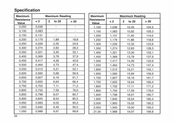
Note: The decimal point position in the MaximumResistance value column is correct for resistancereadings < 2 Ω. For the 2 Ω to 20 Ω column and the >20 Ω column, the decimal point should be movedaccordingly. For maximum readings in excess of 200 Ωuse the right hand column and adjust the decimal pointaccordingly.
The table gives the maximum reading that would beallowed for a known maximum resistance value,assuming the instrument is used as specified.
If a maximum resistance is known, this value is foundfrom the left hand column. The maximum reading to be
given by the instrument is found by reading across tothe appropriate of the three right hand columns,depending upon the range of the value to be measured.
For example If 10 Ω is the value of the maximumresistance, since this is less than 20 Ω, the centrecolumn of the three right hand columns is used. Thisshows that a reading of less than 9,49 Ω will ensurethat, allowing for instrument tolerances, the measuredresistance will be less than 10 Ω.
A maximum value may be given to a measurement byusing the table in reverse. For example, a reading of1,545 Ω would give a maximum limit to the resistancevalue of between 1,600 Ω and 1,650 Ω. Interpolationcan be used to increase the accuracy if required.
Note: This table can only be used for readings from aDET2/2.
33
MaximumResistance
Value < 2 > 20 2 to 20
Maximum Reading MaximumResistance
Value < 2 > 20 2 to 20
Maximum Reading
0,050 -0,036 -
0,100 -0,083 -
0,150 -0,131 -
0,200 18,80,179 1,88
0,250 23,60,226 2,35
0,300 28,30,274 2,83
0,350 33,10,321 3,30
0,400 37,90,369 3,78
0,450 42,60,417 4,26
0,500 47,40,464 4,73
0,550 52,10,512 5,21
0,600 56,90,560 5,68
0,650 61,70,607 6,16
0,700 66,40,655 6,64
0,750 71,20,702 7,11
0,800 76,00,750 7,59
0,850 80,70,798 8,07
0,900 85,50,845 8,54
0,950 90,20,983 9,02
1,000 95,00,940 9,49
1,050 99,80,988 9,97
1,100 104,51,036 10,45
1,150 109,31,083 10,92
1,200 114,01,131 11,40
1,250 118,81,179 11,88
1,300 123,61,226 12,35
1,350 128,31,274 12,83
1,400 133,11,321 13,30
1,450 137,91,369 13,78
1,500 142,61,417 14,26
1,550 147,41,464 14,73
1,600 152,11,512 15,21
1,650 156,91,560 15,69
1,700 161,71,607 16,16
1,750 166,41,655 16,64
1,800 171,21,702 17,11
1,850 176,01,750 17,59
1,900 180,71,798 18,07
1,950 185,41,845 18,54
2,000 190,21,893 19,02
2,050 195,01,940 19,50
21,00 199,81,988 19,97
Specification
34

Accessories
SUPPLIED Part Number
User Guide 6171-428Battery charging Power cord
OPTIONAL
Publications‘Getting Down to Earth’ AVTM25-TA
Four Terminal Earth Testing kit 6310 - 755Carrying bag containing:-Club hammer, 4 x spikes, two spike extractors, 3m (x2) cable and 30m, 50m of cable on winders.
Four Terminal Compact Earth 6210 - 161Testing kitCompact carrying bag containing:-2 x push in spikes, 3m, 15m, 30, and 50m of cable on cable tidy.
Three Terminal Compact Earth 6210 - 160Testing Kit Compact carrying bag containing:-2 x push spikes, 3m, 15m and 30m of cable on a cable tidy.
U.S. OPTIONS Cat. NumberStandard Accessory kit 250579Canvas case containing:-2 x 20 in rods, leads (25,50 &100 ft)
Deluxe Accessory kit 250581Padded case to hold instrument,2 x 20 in rods, leads (25,50 &100 ft)
Soil Resistivity kit 250586Padded case to hold instrument,44 x 20 in rods and test leads (4 x 50ft )
35
36
Values of Pt / EC for Values of μ
μ 0 1 2 3 4 5 6 7 8 9
0.40 0.6432 0.6431 0.6429 0.6428 0.6426 0.6425 0.6423 0.6422 0.6420 0.6420.41 0.6418 0.6417 0.6415 0.6414 0.6412 0.6411 0.641 0.6408 0.6407 0.64050.42 0.6404 0.6403 0.6401 0.64 0.6398 0.6397 0.6395 0.6394 0.6393 0.63910.43 0.639 0.6388 0.6387 0.6385 0.6384 0.6383 0.6381 0.638 0.6378 0.63770.44 0.6375 0.6374 0.6372 0.6371 0.637 0.6368 0.6367 0.6365 0.6364 0.63620.45 0.6361 0.6359 0.6358 0.6357 0.6355 0.6354 0.6352 0.6351 0.6349 0.63480.46 0.6346 0.6345 0.6344 0.6342 0.6341 0.6339 0.6338 0.6336 0.6335 0.63330.47 0.6332 0.633 0.6329 0.6328 0.6326 0.6325 0.6323 0.6322 0.632 0.63190.48 0.6317 0.6316 0.6314 0.6313 0.6311 0.631 0.6308 0.6307 0.6306 0.63040.49 0.6303 0.6301 0.63 0.6298 0.6297 0.6295 0.6294 0.6292 0.6291 0.62890.50 0.6288 0.6286 0.6285 0.6283 0.6282 0.628 0.6279 0.6277 0.6276 0.62740.51 0.6273 0.6271 0.627 0.6268 0.6267 0.6266 0.6264 0.6263 0.6261 0.6260.52 0.6258 0.6257 0.6255 0.6254 0.6252 0.6251 0.6249 0.6248 0.6246 0.62450.53 0.6243 0.6242 0.624 0.6239 0.6237 0.6235 0.6234 0.6232 0.6231 0.62290.54 0.6228 0.6226 0.6225 0.6223 0.6222 0.622 0.6219 0.6217 0.6216 0.62140.55 0.6213 0.6211 0.621 0.6208 0.6207 0.6205 0.6204 0.6202 0.6201 0.61990.56 0.6198 0.6196 0.6194 0.6193 0.6191 0.619 0.6188 0.6187 0.6185 0.61840.57 0.6182 0.6181 0.6179 0.6178 0.6176 0.6174 0.6173 0.6171 0.617 0.61680.58 0.6167 0.6165 0.6164 0.6162 0.6161 0.6159 0.6157 0.6156 0.6154 0.61530.59 0.6151 0.615 0.6148 0.6147 0.6145 0.6143 0.6142 0.614 0.6139 0.61370.60 0.6136 0.6134 0.6133 0.6131 0.6129 0.6128 0.6126 0.6125 0.6123 0.61220.61 0.612 0.6118 0.6117 0.6115 0.6114 0.6112 0.6111 0.6109 0.6107 0.61060.62 0.6104 0.6103 0.6101 0.6099 0.6098 0.6096 0.6095 0.6093 0.6092 0.6090.63 0.6088 0.6087 0.6085 0.6084 0.6082 0.608 0.6079 0.6077 0.6076 0.6074
Chart for use with the Slope Method
37
μ 0 1 2 3 4 5 6 7 8 9
0.64 0.6072 0.6071 0.6069 0.6068 0.6066 0.6064 0.6063 0.6061 0.606 0.60580.65 0.6056 0.6055 0.6053 0.6052 0.605 0.6048 0.6047 0.6045 0.6043 0.60420.66 0.604 0.6039 0.6037 0.6035 0.6034 0.6032 0.6031 0.6029 0.6027 0.60260.67 0.6024 0.6022 0.6021 0.6019 0.6017 0.6016 0.6014 0.6013 0.6011 0.60090.68 0.6008 0.6006 0.6004 0.6003 0.6001 0.5999 0.5998 0.5996 0.5994 0.59930.69 0.5991 0.599 0.5988 0.5986 0.5985 0.5983 0.5981 0.598 0.5978 0.59760.70 0.5975 0.5973 0.5971 0.597 0.5968 0.5966 0.5965 0.5963 0.5961 0.5960.71 0.5958 0.5956 0.5955 0.5953 0.5951 0.595 0.5948 0.5946 0.5945 0.59430.72 0.5941 0.594 0.5938 0.5936 0.5934 0.5933 0.5931 0.5929 0.5928 0.59260.73 0.5924 0.5923 0.5921 0.5919 0.5918 0.5916 0.5914 0.5912 0.5911 0.59090.74 0.5907 0.5906 0.5904 0.5902 0.5901 0.5899 0.5897 0.5895 0.5894 0.58920.75 0.589 0.5889 0.5887 0.5885 0.5883 0.5882 0.588 0.5878 0.5876 0.58750.76 0.5873 0.5871 0.587 0.5868 0.5866 0.5864 0.5863 0.5861 0.5859 0.58570.77 0.5856 0.5854 0.5852 0.585 0.5849 0.5847 0.5845 0.5843 0.5842 0.5840.78 0.5838 0.5836 0.5835 0.5833 0.5831 0.5829 0.5828 0.5826 0.5824 0.58220.79 0.5821 0.5819 0.5817 0.5815 0.5813 0.5812 0.581 0.5808 0.5806 0.58050.80 0.5803 0.5801 0.5799 0.5797 0.5796 0.5794 0.5792 0.579 0.5789 0.57870.81 0.5785 0.5783 0.5781 0.578 0.5778 0.5776 0.5774 0.5772 0.5771 0.57690.82 0.5767 0.5765 0.5763 0.5762 0.576 0.5758 0.5756 0.5754 0.5752 0.57510.83 0.5749 0.5747 0.5745 0.5743 0.5742 0.574 0.5738 0.5736 0.5734 0.57320.84 0.5731 0.5729 0.5727 0.5725 0.5723 0.5721 0.572 0.5718 0.5716 0.57140.85 0.5712 0.571 0.5708 0.5707 0.5705 0.5703 0.5701 0.5699 0.5697 0.56950.86 0.5694 0.5692 0.569 0.5688 0.5686 0.5684 0.5682 0.568 0.5679 0.56770.87 0.5675 0.5673 0.5671 0.5669 0.5667 0.5665 0.5664 0.5662 0.566 0.56580.88 0.5656 0.5654 0.5652 0.565 0.5648 0.5646 0.5645 0.5643 0.5641 0.56390.89 0.5637 0.5635 0.5633 0.5631 0.5629 0.5627 0.5625 0.5624 0.5622 0.562

38
μ 0 1 2 3 4 5 6 7 8 9
0.90 0.5618 0.5616 0.5614 0.5612 0.561 0.5608 0.5606 0.5604 0.5602 0.560.91 0.5598 0.5596 0.5595 0.5593 0.5591 0.5589 0.5587 0.5585 0.5583 0.55810.92 0.5579 0.5577 0.5575 0.5573 0.5571 0.5569 0.5567 0.5565 0.5563 0.55610.93 0.5559 0.5557 0.5555 0.5553 0.5551 0.5549 0.5547 0.5545 0.5543 0.55410.94 0.5539 0.5537 0.5535 0.5533 0.5531 0.5529 0.5527 0.5525 0.5523 0.55210.95 0.5519 0.5517 0.5515 0.5513 0.5511 0.5509 0.5507 0.5505 0.5503 0.55010.96 0.5499 0.5497 0.5495 0.5493 0.5491 0.5489 0.5487 0.5485 0.5483 0.54810.97 0.5479 0.5476 0.5474 0.5472 0.547 0.5468 0.5466 0.5464 0.5462 0.5460.98 0.5458 0.5456 0.5454 0.5452 0.545 0.5447 0.5445 0.5443 0.5441 0.54390.99 0.5437 0.5435 0.5433 0.5431 0.5429 0.5427 0.5424 0.5422 0.542 0.54181.00 0.5416 0.5414 0.5412 0.541 0.5408 0.5405 0.5403 0.5401 0.5399 0.53971.01 0.5395 0.5393 0.539 0.5388 0.5386 0.5384 0.5382 0.538 0.5378 0.53751.02 0.5373 0.5371 0.5369 0.5367 0.5365 0.5362 0.536 0.5358 0.5356 0.53541.03 0.5352 0.5349 0.5347 0.5345 0.5343 0.5341 0.5338 0.5336 0.5334 0.53321.04 0.533 0.5327 0.5325 0.5323 0.5321 0.5319 0.5316 0.5314 0.5312 0.5311.05 0.5307 0.5305 0.5303 0.5301 0.5298 0.5296 0.5294 0.5292 0.529 0.52871.06 0.5285 0.5283 0.5281 0.5278 0.5276 0.5274 0.5271 0.5269 0.5267 0.52651.07 0.5262 0.526 0.5258 0.5256 0.5253 0.5251 0.5249 0.5246 0.5244 0.52421.08 0.5239 0.5237 0.5235 0.5233 0.523 0.5228 0.5226 0.5223 0.5221 0.52191.09 0.5216 0.5214 0.5212 0.5209 0.5207 0.5205 0.5202 0.52 0.5197 0.51951.10 0.5193 0.519 0.5188 0.5186 0.5183 0.5181 0.5179 0.5176 0.5174 0.51711.11 0.5169 0.5167 0.5164 0.5162 0.5159 0.5157 0.5155 0.5152 0.515 0.51471.12 0.5145 0.5143 0.514 0.5138 0.5135 0.5133 0.513 0.5128 0.5126 0.51231.13 0.5121 0.5118 0.5116 0.5113 0.5111 0.5108 0.5106 0.5103 0.5101 0.50991.14 0.5096 0.5094 0.5091 0.5089 0.5086 0.5084 0.5081 0.5079 0.5076 0.50741.15 0.5071 0.5069 0.5066 0.5064 0.5061 0.5059 0.5056 0.5053 0.5051 0.5048
Chart for use with the Slope Method (continued)

39
μ 0 1 2 3 4 5 6 7 8 9
1.16 0.5046 0.5043 0.5041 0.5038 0.5036 0.5033 0.5031 0.5028 0.5025 0.50231.17 0.502 0.5018 0.5015 0.5013 0.501 0.5007 0.5005 0.5002 0.5 0.49971.18 0.4994 0.4992 0.4989 0.4987 0.4984 0.4981 0.4979 0.4976 0.4973 0.49711.19 0.4968 0.4965 0.4963 0.496 0.4957 0.4955 0.4952 0.4949 0.4947 0.49441.20 0.4941 0.4939 0.4936 0.4933 0.4931 0.4928 0.4925 0.4923 0.492 0.49171.21 0.4914 0.4912 0.4909 0.4906 0.4903 0.4901 0.4898 0.4895 0.4892 0.4891.22 0.4887 0.4884 0.4881 0.4879 0.4876 0.4873 0.487 0.4868 0.4865 0.48621.23 0.4859 0.4856 0.4854 0.4851 0.4848 0.4845 0.4842 0.4839 0.4837 0.48341.24 0.4831 0.4828 0.4825 0.4822 0.4819 0.4817 0.4814 0.4811 0.4808 0.48051.25 0.4802 0.4799 0.4796 0.4794 0.4791 0.4788 0.4785 0.4782 0.4779 0.47761.26 0.4773 0.477 0.4767 0.4764 0.4761 0.4758 0.4755 0.4752 0.475 0.47471.27 0.4744 0.4741 0.4738 0.4735 0.4732 0.4729 0.4726 0.4723 0.472 0.47171.28 0.4714 0.4711 0.4707 0.4704 0.4701 0.4698 0.4695 0.4692 0.4689 0.46861.29 0.4683 0.468 0.4677 0.4674 0.4671 0.4668 0.4664 0.4661 0.4658 0.46551.30 0.4652 0.4649 0.4646 0.4643 0.4639 0.4636 0.4633 0.463 0.4627 0.46241.31 0.462 0.4617 0.4614 0.4611 0.4608 0.4604 0.4601 0.4598 0.4595 0.45921.32 0.4588 0.4585 0.4582 0.4579 0.4575 0.4572 0.4569 0.4566 0.4562 0.45591.33 0.4556 0.4552 0.4549 0.4546 0.4542 0.4539 0.4536 0.4532 0.4529 0.45261.34 0.4522 0.4519 0.4516 0.4512 0.4509 0.4506 0.4502 0.4499 0.4495 0.44921.35 0.4489 0.4485 0.4482 0.4478 0.4475 0.4471 0.4468 0.4464 0.4461 0.44581.36 0.4454 0.4451 0.4447 0.4444 0.444 0.4437 0.4433 0.443 0.4426 0.44221.37 0.4419 0.4415 0.4412 0.4408 0.4405 0.4401 0.4398 0.4394 0.439 0.43871.38 0.4383 0.4379 0.4376 0.4372 0.4369 0.4365 0.4361 0.4358 0.4354 0.4351.39 0.4347 0.4343 0.4339 0.4335 0.4332 0.4328 0.4324 0.4321 0.4317 0.43131.40 0.4309 0.4306 0.4302 0.4298 0.4294 0.429 0.4287 0.4283 0.4279 0.42751.41 0.4271 0.4267 0.4264 0.426 0.4256 0.4252 0.4248 0.4244 0.424 0.4236

40
μ 0 1 2 3 4 5 6 7 8 9
1.42 0.4232 0.4228 0.4225 0.4221 0.4217 0.4213 0.4209 0.4205 0.4201 0.41971.43 0.4193 0.4189 0.4185 0.4181 0.4177 0.4173 0.4168 0.4164 0.416 0.41561.44 0.4152 0.4148 0.4144 0.414 0.4136 0.4131 0.4127 0.4123 0.4119 0.41151.45 0.4111 0.4106 0.4102 0.4098 0.4094 0.409 0.4085 0.4081 0.4077 0.40721.46 0.4068 0.4064 0.406 0.4055 0.4051 0.4047 0.4042 0.4038 0.4034 0.40291.47 0.4025 0.402 0.4016 0.4012 0.4007 0.4003 0.3998 0.3994 0.3989 0.39851.48 0.398 0.3976 0.3971 0.3967 0.3962 0.3958 0.3953 0.3949 0.3944 0.39391.49 0.3935 0.393 0.3925 0.3921 0.3916 0.3912 0.3907 0.3902 0.3897 0.38931.50 0.3888 0.3883 0.3878 0.3874 0.3869 0.3864 0.3859 0.3855 0.385 0.38451.51 0.384 0.3835 0.383 0.3825 0.3821 0.3816 0.3811 0.3806 0.3801 0.37961.52 0.3791 0.3786 0.3781 0.3776 0.3771 0.3766 0.3761 0.3756 0.3751 0.37451.53 0.374 0.3735 0.373 0.3725 0.372 0.3715 0.3709 0.3704 0.3699 0.36941.54 0.3688 0.3683 0.3678 0.3673 0.3667 0.3662 0.3657 0.3651 0.3646 0.3641.55 0.3635 0.363 0.3624 0.3619 0.3613 0.3608 0.3602 0.3597 0.3591 0.35861.56 0.358 0.3574 0.3569 0.3563 0.3558 0.3552 0.3546 0.354 0.3535 0.35291.57 0.3523 0.3518 0.3512 0.3506 0.35 0.3494 0.3488 0.3483 0.3477 0.34711.58 0.3465 0.3459 0.3453 0.3447 0.3441 0.3435 0.3429 0.3423 0.3417 0.34111.59 0.3405 0.3399 0.3392 0.3386 0.338 0.3374 0.3368 0.3361 0.3355 0.3349
Chart for use with the Slope Method (continued)

The instrument circuit contains static sensitive devices,and care must be taken in handling the printed circuitboard. If the protection of an instrument has beenimpaired it should not be used, and be sent for repair bysuitably trained and qualified personnel. The protection islikely to be impaired if, for example, the instrument showsvisible damage, fails to perform the intendedmeasurements, has been subjected to prolonged storageunder unfavourable conditions, or has been exposed tosevere transport stresses.
New Instruments are Guaranteed for 1 Year from theDate of Purchase by the User.
Note: Any unauthorized prior repair or adjustment willautomatically invalidate the Warranty.
Instrument Repair and Spare PartsFor service requirements for Megger Instruments contact
Megger Limited or MeggerArchcliffe Road Valley Forge Corporate CenterDover 2621 Van Buren AvenueKent CT17 9EN Norristown England PA 19403 U.S.A.Tel: +44 (0)1304 502243 Tel: +1 (610) 676-8579Fax: +44 (0)1304 207342 Fax: +1 (610) 676-8625
or an approved repair company.
Approved Repair CompaniesA number of independent instrument repair companies have been approved for repair work on mostMegger instruments, using genuine Megger spare parts.Consult the Appointed Distributor/Agent regarding spareparts, repair facilities and advice on the best course ofaction to take.
Returning an Instrument for RepairIf returning an instrument to the manufacturer for repair, itshould be sent, freight pre-paid, to the appropriateaddress. A copy of the Invoice and of the packing noteshould be sent simultaneously by airmail to expediteclearance through Customs. A repair estimate showingfreight return and other charges will be submitted to thesender, if required, before work on the instrumentcommences.
41
Repair and Warranty

42
M
DET2/2Contrôleur de masse numérique
Guide de l’utilisateur
43
44
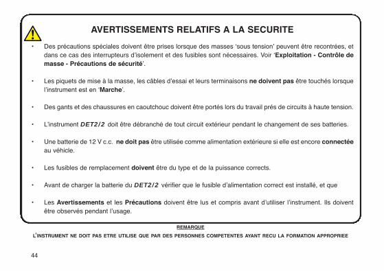
AVERTISSEMENTS RELATIFS A LA SECURITE
• Des précautions spéciales doivent être prises lorsque des masses ‘sous tension’ peuvent être recontrées, etdans ce cas des interrupteurs d’isolement et des fusibles sont nécessaires. Voir ‘Exploitation - Contrôle demasse - Précautions de sécurité’.
• Les piquets de mise à la masse, les câbles d’essai et leurs terminaisons ne doivent pas être touchés lorsquel’instrument est en ‘Marche’.
• Des gants et des chaussures en caoutchouc doivent être portés lors du travail prés de circuits à haute tension.
• L’instrument DET2/2 doit être débranché de tout circuit extérieur pendant le changement de ses batteries.
• Une batterie de 12 V c.c. ne doit pas être utilisée comme alimentation extérieure si elle est encore connectéeau véhicle.
• Les fusibles de remplacement doivent être du type et de la puissance corrects.
• Avant de charger la batterie du DET2/2 vérifier que le fusible d’alimentation correct est installé, et que
• Les Avertissements et les Précautions doivent être lus et compris avant d’utiliser l’instrument. Ils doiventêtre observés pendant l’usage.
REMARQUE
L’INSTRUMENT NE DOIT PAS ETRE UTILISE QUE PAR DES PERSONNES COMPETENTES AYANT RECU LA FORMATION APPROPRIEE
Avertissements relatifs à la sécurité 44
Table des matières 45
Description générale 46
Applications 47
Caractéristiques et commandes 48
Configuration initiale 49
Mise en place des piquets d’essai 50
Précautions de sécurité de contrôle de masse 51
Exploitation
Procédure générale d’essai 53
Ajustements des conditions d’essai 53
Messages de l’affichage 54
Messages d’erreur 55
Charge de la batterie 56
Essai de continuité 58
Spécifications 59
Accessoires 64
Réparations et Garantie 65
Symboles utilisés sur cet instrument
Attention: Consultez les notes jointes.
Equipement protegé par un isolement double ou renforcé (Classe II).
Cet équipement respecte les directives en viguer de l’UE.
Table des matière User Guide p2 Gebrauchsanleitung s67 Guía del usuario p91
45
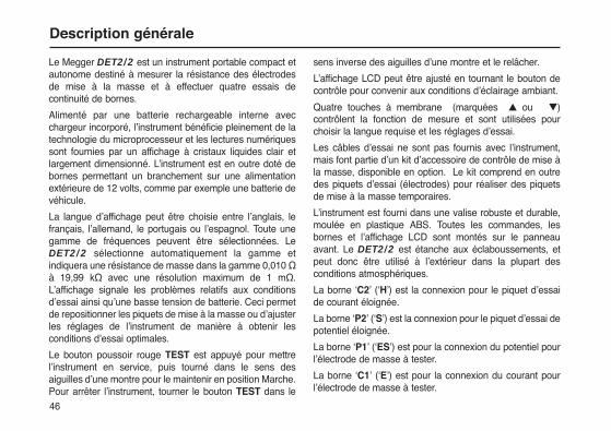
Le Megger DET2/2 est un instrument portable compact etautonome destiné à mesurer la résistance des électrodesde mise à la masse et à effectuer quatre essais decontinuité de bornes.
Alimenté par une batterie rechargeable interne avecchargeur incorporé, l’instrument bénéficie pleinement de latechnologie du microprocesseur et les lectures numériquessont fournies par un affichage à cristaux liquides clair etlargement dimensionné. L’instrument est en outre doté debornes permettant un branchement sur une alimentationextérieure de 12 volts, comme par exemple une batterie devéhicule.
La langue d’affichage peut être choisie entre l’anglais, lefrançais, l’allemand, le portugais ou l’espagnol. Toute unegamme de fréquences peuvent être sélectionnées. LeDET2/2 sélectionne automatiquement la gamme etindiquera une résistance de masse dans la gamme 0,010 Ωà 19,99 kΩ avec une résolution maximum de 1 mΩ.L’affichage signale les problèmes relatifs aux conditionsd’essai ainsi qu’une basse tension de batterie. Ceci permetde repositionner les piquets de mise à la masse ou d’ajusterles réglages de l’instrument de manière à obtenir lesconditions d’essai optimales.
Le bouton poussoir rouge TEST est appuyé pour mettrel’instrument en service, puis tourné dans le sens desaiguilles d’une montre pour le maintenir en position Marche.Pour arrêter l’instrument, tourner le bouton TEST dans le
sens inverse des aiguilles d’une montre et le relâcher.
L’affichage LCD peut être ajusté en tournant le bouton decontrôle pour convenir aux conditions d’éclairage ambiant.
Quatre touches à membrane (marquées ▲ ou ▼)contrôlent la fonction de mesure et sont utilisées pourchoisir la langue requise et les réglages d’essai.
Les câbles d’essai ne sont pas fournis avec l’instrument,mais font partie d’un kit d’accessoire de contrôle de mise àla masse, disponible en option. Le kit comprend en outredes piquets d’essai (électrodes) pour réaliser des piquetsde mise à la masse temporaires.
L’instrument est fourni dans une valise robuste et durable,moulée en plastique ABS. Toutes les commandes, lesbornes et l’affichage LCD sont montés sur le panneauavant. Le DET2/2 est étanche aux éclaboussements, etpeut donc être utilisé à l’extérieur dans la plupart desconditions atmosphériques.
La borne ‘C2’ (‘H’) est la connexion pour le piquet d’essaide courant éloignée.
La borne ‘P2’ (‘S’) est la connexion pour le piquet d’essai depotentiel éloignée.
La borne ‘P1’ (‘ES’) est pour la connexion du potentiel pourl’électrode de masse à tester.
La borne ‘C1’ (‘E’) est pour la connexion du courant pourl’électrode de masse à tester.
Description générale
46
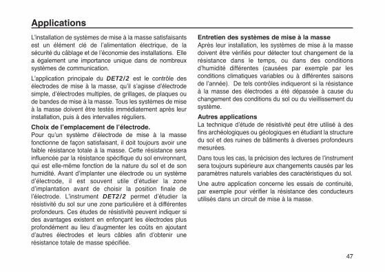
L’installation de systèmes de mise à la masse satisfaisantsest un élément clé de l’alimentation électrique, de lasécurité du câblage et de l’économie des installations. Ellea également une importance unique dans de nombreuxsystèmes de communication.
L’application principale du DET2/2 est le contrôle desélectrodes de mise à la masse, qu’il s’agisse d’électrodesimple, d’électrodes multiples, de grillages, de plaques oude bandes de mise à la masse. Tous les systèmes de miseà la masse doivent être testés immédiatement après leurinstallation, puis à des intervalles réguliers.
Choix de l’emplacement de l’électrode.Pour qu’un système d’électrode de mise à la massefonctionne de façon satisfaisant, il doit toujours avoir unefaible résistance totale à la masse. Cette résistance serainfluencée par la résistance spécifique du sol environnant,qui est elle-même fonction de la nature du sol et de sonhumidité. Avant d’implanter une électrode ou un systèmed’électrode, il est souvent utile d’étudier la zoned’implantation avant de choisir la position finale del’électrode. L’instrument DET2/2 permet d’étudier larésistivité du sol sur une zone particulière et à différentesprofondeurs. Ces études de résistivité peuvent indiquer sides avantages existent en enfonçant les électrodes plusprofondément au lieu d’augmenter les coûts en ajoutantd’autres électrodes et leurs câbles afin d’obtenir unerésistance totale de masse spécifiée.
Entretien des systèmes de mise à la masseAprès leur installation, les systèmes de mise à la massedoivent être vérifiés pour détecter tout changement de larésistance dans le temps, ou dans des conditionsd’humidité différentes (causées par exemple par lesconditions climatiques variables ou à différentes saisonsde l’année). De tels contrôles indiqueront si la résistanceà la masse des électrodes a été dépassée à cause duchangement des conditions du sol ou du vieillissement dusystème.
Autres applicationsLa technique d’étude de résistivité peut être utilisé à desfins archéologiques ou géologiques en étudiant la structuredu sol et des ruines de bâtiments à diverses profondeursmesurées.
Dans tous les cas, la précision des lectures de l’instrumentsera toujours supérieure aux changements causés par lesparamètres naturels variables des caractéristiques du sol.
Une autre application concerne les essais de continuité,par exemple pour vérifier la résistance des conducteursutilisés dans un circuit de mise à la masse.
Applications
47
48
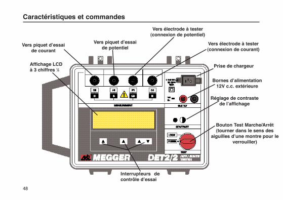
Caractéristiques et commandes
Vers électrode à tester(connexion de potentiel)
Vers électrode à tester(connexion de courant)
Prise de chargeur
Bornes d’alimentation12V c.c. extérieure
Réglage de contrastede l’affichage
Vers piquet d’essai de potentiel
Vers piquet d’essai de courant
Bouton Test Marche/Arrêt(tourner dans le sens des
aiguilles d’une montre pour leverrouiller)
Affichage LCD à 3 chiffres 1⁄2
Interrupteurs decontrôle d’essai
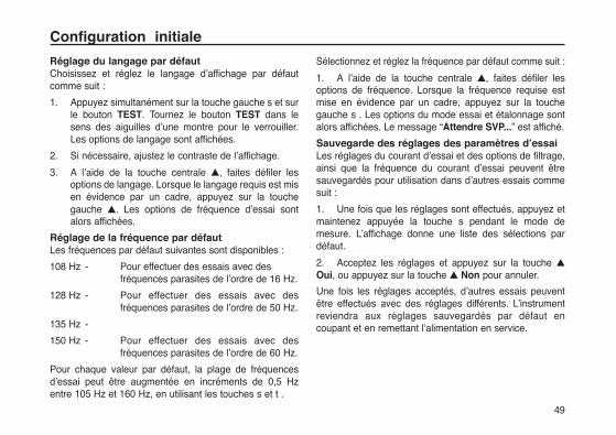
Réglage du langage par défautChoisissez et réglez le langage d’affichage par défautcomme suit :
1. Appuyez simultanément sur la touche gauche s et sur le bouton TEST. Tournez le bouton TEST dans le sens des aiguilles d’une montre pour le verrouiller. Les options de langage sont affichées.
2. Si nécessaire, ajustez le contraste de l’affichage.
3. A l’aide de la touche centrale ▲, faites défiler les options de langage. Lorsque le langage requis est mis en évidence par un cadre, appuyez sur la touche gauche ▲. Les options de fréquence d’essai sont alors affichées.
Réglage de la fréquence par défautLes fréquences par défaut suivantes sont disponibles :
108 Hz - Pour effectuer des essais avec des fréquences parasites de l’ordre de 16 Hz.
128 Hz - Pour effectuer des essais avec des fréquences parasites de l’ordre de 50 Hz.
135 Hz -
150 Hz - Pour effectuer des essais avec des fréquences parasites de l’ordre de 60 Hz.
Pour chaque valeur par défaut, la plage de fréquencesd’essai peut être augmentée en incréments de 0,5 Hzentre 105 Hz et 160 Hz, en utilisant les touches s et t .
Sélectionnez et réglez la fréquence par défaut comme suit :
1. A l’aide de la touche centrale ▲, faites défiler lesoptions de fréquence. Lorsque la fréquence requise estmise en évidence par un cadre, appuyez sur la touchegauche s . Les options du mode essai et étalonnage sontalors affichées. Le message “Attendre SVP...” est affiché.
Sauvegarde des réglages des paramètres d’essaiLes réglages du courant d’essai et des options de filtrage,ainsi que la fréquence du courant d’essai peuvent êtresauvegardés pour utilisation dans d’autres essais commesuit :
1. Une fois que les réglages sont effectués, appuyez etmaintenez appuyée la touche s pendant le mode demesure. L’affichage donne une liste des sélections pardéfaut.
2. Acceptez les réglages et appuyez sur la touche ▲
Oui, ou appuyez sur la touche ▲ Non pour annuler.
Une fois les réglages acceptés, d’autres essais peuventêtre effectués avec des réglages différents. L’instrumentreviendra aux réglages sauvegardés par défaut encoupant et en remettant l’alimentation en service.
Configuration initiale
49

Pour les essais d’électrodes de mise à la masse et pour lesétudes de résistivité du sol, les câbles d’essai del’instrument sont connectés à des piquets enfoncés dans lesol. La façon dont les connexions sont réalisées estfonction du type d’essai entrepris, et les détails appropriéssont fournis à la section “Techniques de mesure”.
Les piquets d’essai et des câbles d’essai de grandelongueur sont requis pour tous les types d’essai de masse,et les kits optionnels d’essai de masse contiennent tous lematériel de base. Voir ’Accessoires’.
1. Enfoncer le piquet d’essai de Courant dans le sol à 30 ou 50 mètres de l’électrode de mise à la masse à tester.
2. Connecter ce piquet à la borne ‘C2’ (‘H’) de l’instrument.
3. Enfoncer le piquet d’essai de Potentiel dans le sol à mi-chemin entre le piquet d’essai de courant et l’électrode de mise à la masse, et aligné par rapport à ces deux électrodes.
4. Connecter ce piquet à la borne ‘P2’ (‘S’) de l’instrument.
5. Lors de l’acheminement des câbles d’essai vers chaque piquet éloigné, éviter de poser les câbles trop près l’un de l’autre.
Mise en place des piquets d’essai
50

51
Isolement ou doublage des électrodesIl est préférable d’isoler l’électrode de mise à la masse àtester du circuit qu’elle protège avant d’effectuer l’essai, demanière à ce que seulement la masse soit mesurée et nonpas le circuit complet. Une fois que l’électrode estdéconnectée, les circuits et les équipements doivent êtredésexcités. Cependant, si cela n’est pas possible,l’électrode de masse doit être doublée de manière à ce quelorsqu’elle est déconnectée pour les essais, la deuxièmeélectrode assure la protection nécessaire des circuits.
Précautions de sécurité relatives aux masses‘sous tension’Le DET2/2 permet de contrôler la masse à une tensionrelativement sûre en utilisant une onde carrée de 50 Vefficace à une fréquence nominale de 128 Hz. A l’usage,l’instrument n’est normalement connecté qu’à desélectrodes qui sont au potentiel de la masse.
Une masse ‘sous tension’ est une masse qui transportedu courant de l’alimentation secteur, ou qui pourrait le fairedans des conditions de faute.
Le travail autour des centrales électriques ou des sous-stations présente des risques car de gros gradients depotentiel se produiront à la masse en cas de panne dephase à la masse. Un conducteur qui est connecté à lamasse à des dizaines de mètres ne sera plus au mêmepotentiel que la masse locale, et dans certains cas pourrait
dépasser 1 kV. Les précautions de sécurité suivantes sontpar conséquent essentielles.
1. Toutes les personnes mises en jeu doivent être formées et compétentes en ce qui concerne les procédures d’isolement et de sécurité du système sur lequel elles travaillent. Il convient de leur souligner de ne pas toucher à l’électrode de mise à la masse, aux câbles d’essai, ou à leurs bornes en cas de possibilité de masse ‘sous tension’. Par ailleurs, il est conseillé à ces personnes de porter des gants en caoutchouc, des chaussures à semelle en caoutchouc, et de se tenir sur des tapis en caoutchouc.
2. Les bornes ‘P2’ et ‘C2’ doivent être connectées par l’intermédiaire d’un interrupteur d’isolement bipolaire d’une puissance suffisante pour résister à la tension et au courant de faute maximum. L’interrupteurd’isolement doit être ouvert pendant toutes les opérations entraînant le contact du personnel avec les piquets d’essai éloignés ou les câbles de connexion, par exemple lors du changement de position.
Si des interrupteurs d’isolement ne peuvent pas êtreutilisés, les câbles d’essai doivent être débranchés del’instrument avant de manipuler les piquets éloignés ou lescâbles. Lorsque les connexions éloignées sont réalisées,les connexions finales peuvent être effectuées surl’instrument à l’aide de prises isolées, en s’assurant quel’opérateur prenne des précautions adéquates et
Précautions de sécurité de contrôle de masse
Précautions de sécurité de contrôle de masse
52
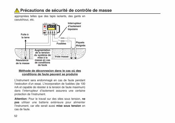
appropriées telles que des tapis isolants, des gants encaoutchouc, etc.
Méthode de déconnexion dans le cas où desconditions de faute peuvent se produire
L’instrument sera endommagé en cas de faute pendantl’exécution d’un essai. L’incorporation de fusibles (de 100mA et capable de résister à la tension de faute maximum)dans l’interrupteur d’isolement assurera une certaineprotection de l’instrument.
Attention: Pour le travail sur des sites sous tension, nepas utiliser une batterie extérieure pour alimenterl’instrument, car elle serait aussi mise sous tension encas de faute.
������������������������������������Résistance
de la masse
Interrupteurd’isolementbipolaire
Vraie masse
Fusibles Piquetséloignés
Augmentationde la tension
du système demise à la
masse en casde conditions
de faute
Fuite àla terre

53
Procédures générales d’essaiIl est conseillé de charger complètement la batterie duDET2/2 avant de commencer une séquence d’essai. Ledéchargement de la batterie au cours d’un essai encampagne peut être extrêmement ennuyeux.
1. Connectez fermement les bornes de l’instrument à leur electrode de masse et piquets d’essai respectifs. Voir ’Mise en place des piquets d’essai’ et ’Techniques de mesure’.
2. Appuyez, et maintenez appuyé, le bouton TEST, ou tournez le à la position de Verrouillage.
3. Si nécessaire, effectuez un essai ’Piquet P’ pour vérifier la continuité du circuit de potentiel.
4. La valeur de la résistance mesurée est indiquée dans l’affichage secondaire après quelques instants, une fois que le message “Attendre SVP ...” a disparu.
Ajustements des conditions d’essaiSi l’affichage secondaire indique qu’une mesure précise ne peutpas être obtenue, il est possible de modifier les conditionsd’essai pour obtenir les conditions optimales pour l’essai. Un ouplusieurs des ajustements suivants peuvent être utilisés:
Fréquence du courant d’essaiA l’aide des touches ▲ et ▼ de droite, augmentez oudiminuez la plage de fréquence du courant d’essai. Voir’Configuration initiale’ et ’Mise en place des piquetsd’essai’.
I bas / I hautA l’aide de la touche ▲ centrale, faites défiler les options degauche pour sélectionner l’option ’Courant‘. Appuyez surla touche ▲ de gauche pour passer de ”I bas” à “I haut “.L’option “I haut“ résout les problèmes posés par larésistance des piquets aux courants élevés.. NB: Larésistance du circuit de courant est constamment contrôléependant un essai. Si elle est trop élevée, un message à ceteffet est affiché.
FiltreA l’aide de la touche ▲ centrale, faites défiler les options degauche pour sélectionner l’option “Filtre“. Appuyez sur latouche ▲ de gauche pour passer de ”Filtre non” à ”Filtreoui”. L’option ”Filtre non” aide à réduire le ‘bruit’ affectantla lecture. Le temps pris pour effectuer une mesureaugmente de façon importante lorsque le filtre est activé.
Piquet PA l’aide de la touche ▲ centrale, faites défiler les options degauche pour sélectionner l’option ”Piquet P”. Appuyez surla touche ▲ de gauche pour effectuer automatiquementune vérification de la résistance du circuit de potentiel.
Après une pause de courte durée, le résultat de cette
Exploitation

vérification est affiché dans le panneau secondaire. Siapproprié, la légende “Piquet P” se transforme en”Essuyer” pour pouvoir répéter l’essai lorsque la positiondu piquet, etc. a été modifiée. Appuyez sur la touche ▲centrale, portant maintenant la légende ’Mesure’ pourrépéter la mesure.
NB: Si, pour une raison quelconque, un essai est effectuéavec un circuit de potentiel ouvert, la lecture résultantesera invalide. Pour confirmer que les connexions sont bienen place et pour vérifier la validité de l’essai, il convientd’effectuer une vérification ’Piquet P‘ avant chaque essai.
Gamme automatiqueSi la résistance de masse à mesurer est trop faible, maisqu’un niveau élevé de bruit est présent, couplé à une hauterésistance de courant du piquet, l’instrument prendraautomatiquement une mesure avec une précision moindre.Si la mesure est satisfaisante, la lecture de résistancen’aura que 3 chiffres, le chiffre le moins important étanteffacé.
Une plus grande précision peut être obtenue en :
a) Réduisant la résistance du piquet (par exemple en mouillant le sol, ou en insérant les piquets plus profondément dans le sol.
b) En passant à la position ’I haut’.
c) En éliminant si possible la source de ‘bruit’.
Messages de l’affichage
Divers messages sont affichés lorsqu’approprié, avec lesdéfinitions suivantes:
“Attendre SVP....““Attendre SVP ... mise à zéro”
Ce message signifie que l’instrument effectue desmesures et des essais internes avant d’afficher la lecturede résistance. Les touches ▲ et ▼ restent actives et lesconditions de mesure peuvent être ajustées avantl’affichage de la lecture. Ces messages peuvent apparaîtrede façon répétée en cas de ‘bruit’ élevé, proche de lafréquence de mesure, ou si le circuit de potentiel est malconnecté.
“Circuit ouvert Bornes Courant“Ceci signifie que le courant d’essai est faible, et impliquequ’une résistance >500 kΩ est présente entre les bornesd’essai. Si ce message reste affiché lorsque les bornes’C1’ et ’C2’ sont mises en court-circuit, un fusible interneest éclaté, avec la possibilité d’autre endommagementinterne. Dans ce cas, renvoyez l’instrument au fabricant ouà une société de réparation approuvée. Voir ’Réparationet Garantie’.
“Tension Incorrecte Vérifier Liasons”
Ce message est affiché lorsque les connexions ’P1’ et ’P2’ont été inversées. Vérifier et rectifier selon les besoins.
”Bruit courant haut““Bruit tension haut“
Ces messages sont affichés lorsque le bruit de tension estsupérieur au niveau acceptable, et rend la mesure invalide.
Exploitation
54
La modification de la fréquence d’essai n’aura aucun effetdans ce cas. Si possible, éliminer la source du bruit, ouréduire la résistance du piquet (par exemple en mouillantle sol, ou en enfonçant les plus profondément dans le sol).
Autres messages de l’affichageUn haut niveau de parasites ou une panne d’instrumentpourrait causer l’affichage de l’un des messages suivants:
“Lecture courant erronee“
“Tension incorrecte“
“Zéro courant incorrect“
“Zéro tension incorrect“
“Zéro courant trop”
“Zéro tension trop“
“Zéro courant bruyant“
“Zéro tension bruyant“
La connexion incorrecte des bornes de potentiel peutcauser l’affichage du message “Tension incorrecte”.
Messages d’erreurDes messages d’erreur peuvent apparaître sur la dernièreligne de l’affichage en cas de faute d’instrument ou delogiciel, ou à cause de l’existence de conditions électriquesadverses. Si un message d’erreur apparaît, arrêter leDET2/2, consulter la section ‘Réparation et Garantie’ etrenvoyer l’instrument au fabricant ou à un agent approuvé,
en fournissant les détails du message d’erreur et l’indicedu logiciel.
“Calibration data retrieval error [Erruer d’extractiondes d’etallonnnage] - Se refer au mode d’emploi“Si les données d’étalonnage stockées dans l’instrumentsont incorrectement extraites, le message ci-dessus estaffiché (en anglais) lors de la mise sous tension. Arrêterle DET2/2, consulter la section ‘Réparation et Garantie’et renvoyer l’instrument au fabricant ou à un agentapprouvé, en fournissant les détails du message d’erreuret l’indice du logiciel.“Setup data retrieval error” [Erreur d’extraction desdonnées de configuration]Le langage par défaut, la fréquence et le niveau de courantsont normalement rappelés lorsque l’instrument est missous tension.
Si cette opération échoue, le message ci-dessus estaffiché (en anglais) ainsi que l’option “Essayer“ (denouveau) (pour essayer de lire de nouveau les données )ou ”Manuel” (pour reconfigurer manuellement lesdonnées). Si les fonctions “Essayer” ou “Manuel” nedonnent pas satisfaction, arrêter le DET2/2 consulter lasection ‘Réparation et Garantie’ et renvoyer l’instrumentau fabricant ou à un agent approuvé, en fournissant lesdétails du message d’erreur et l’indice du logiciel.
55
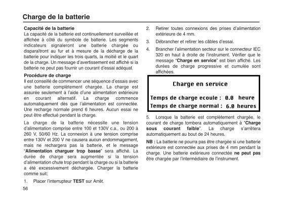
56
Capacité de la batterieLa capacité de la batterie est continuellement surveillée etaffichée à côté du symbole de batterie. Les segmentsindicateurs signaleront une batterie chargée oudisparaîtront au fur et à mesure de la décharge de labatterie pour indiquer les trois quarts, la moitié et le quartde la charge. Un message d’avertissement est affiché si labatterie ne peut pas fournir un courant d’essai adéquat.
Procédure de chargeIl est conseillé de commencer une séquence d’essais avecune batterie complètement chargée. La charge estassurée seulement à l’aide d’une alimentation extérieureen courant alternatif. La charge commenceautomatiquement dès que l’alimentation est connectée.Une recharge normale prend 6 heures. Aucun essai nepeut être effectué pendant la charge.
La charge de la batterie nécessite une tensiond’alimentation comprise entre 100 et 130V c.a., ou 200 à260 V, 50/60 Hz. La connexion à une tension compriseentre 130V et 200 V ne causera aucun endommagement,mais ne rechargera pas la batterie, et le message“Alimentation charguer trop basse” sera affiché. Ladurée de charge sera augmentée si la tensiond’alimentation chute trop pendant la charge ou si la batteriea été excessivement déchargée. Charger la batteriecomme suit:
1. Placer l’interrupteur TEST sur Arrêt.
2. Retirer toutes connexions des prises d’alimentation extérieure de 4 mm.
3. Débrancher et retirer les câbles d’essai.
4. Brancher l’alimentation secteur sur le connecteur IEC 320 en haut à droite de l’instrument. Vérifier que le message “Charge en service” est bien affiché. Les durées de charge progressive et cumulée sont affichées.
5. Lorsque la batterie est complètement chargée, lecourant de charge tombera automatiquement à “Chargesous courant faible”. La charge s’arrêteraautomatiquement au bout de 24 heures.
NB : La batterie ne pourra pas être chargée si une batterieextérieure est connectée aux prises de 4 mm pendant lacharge. Une batterie extérieure connectée ne peut pasêtre chargée par l’intermédiaire de l’instrument.
Charge de la batterie

Prise du cordon d’alimentation de charge debatterieSi la prise du cordon d’alimentation ne convient pas à votretype de prise femelle, ne pas utiliser d’adaptateur. Uncordon d’alimentation approprié doit être utilisé ou, sinécessaire, changer la prise en la coupant du cordon et eninstallant une prise appropriée.
Le code couleur du cordon est le suivant:
Masse (Terre) - Jaune / Vert
Neutre - Bleu
Phase (Ligne) - Marron
Si une prise dotée d’un fusible est employée, monter unfusible de 3 A conforme à BS 1362.
NB: Toute prise coupée du cordon d’alimentation doit êtredétruite étant donné qu’une prise ayant des connexionsnues peut être extrêmement dangereuse si elle est inséréedans une prise secteur sous tension.
Notes relatives à la charge de la batterie1) Ne jamais laisser la batterie à l’état totalement
déchargé. Si l’instrument n’est pas utilisé pendant de longues périodes, recharger la batterie au moins tous les six mois. (Plus souvent si la température de stockage est supérieure à 40°C.
2) La charge de la batterie doit être effectuée dans un environnement sec et à une température comprise entre 0 et 40°C.
3) Si la batterie est chargée dans une pièce, prévoir une ventilation adéquate.
57
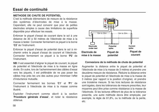
58
Essai de continuité
METHODE DE CHUTE DE POTENTIELC’est la méthode élémentaire de mesure de la résistancedes systèmes d’électrodes de mise à la masse.Cependant, elle ne peut convenir que pour de petitesélectrodes simples à cause des limitations de superficiedisponible pour effectuer les essais.
Enfoncer le piquet d’essai de courant dans le sol à unedistance de 30 à 50 mètres de l’électrode de mise à lamasse à tester. Connecter fermement ce piquet à la borne‘C2’ de l’instrument.
Enfoncer le piquet d’essai de potentiel dans le sol à mi-chemin entre le piquet d’essai de courant et l’électrode.Connecter fermement ce piquet à la borne ‘P2’ del’instrument.
NB: Il est essentiel d’aligner le piquet de courant, le piquetde potentiel et l’électrode de mise à la masse en lignedroite. En outre, lors de l’acheminement des câbles d’essaivers les piquets, il est préférable de ne pas poser lescâbles trop près les uns des autres pour minimiser l’effetd’inductance mutuelle.
Connecter fermement les bornes ’C1’ et ’P1’ del’instrument à l’électrode de mise à la masse commeillustré.
Exploiter l’instrument comme décrit à la section’Procédure générale d’essai’, et noter la résistanceobtenue.
Connexions de la méthode de chute de potentiel
Augmenter la distance entre le piquet de potentiel etl’électrode de mise à la masse de 3 mètres et prendre unedeuxième mesure de résistance. Réduire la distance entrele piquet de potentiel et l’électrode de mise à la masse de3 mètres (par rapport à la position d’origine), et prendreune troisième mesure. Si les trois lectures de résistancesont égales, dans les tolérances de mesure prescrites, leurmoyenne peut être prise comme résistance à la masse del’électrode. Si les lectures diffèrent de plus de la toléranceprescrite, une autre méthode devra être employée, parexemple, la règle de 61,8%, ou la méthode de la pente,etc.
Electrode�under test
Potential �spike
3m 3m
15m to 25m 15m to 25m
�Current�spike
Electrode demise à la masse
Piquet depotentiel
Piquet decourant
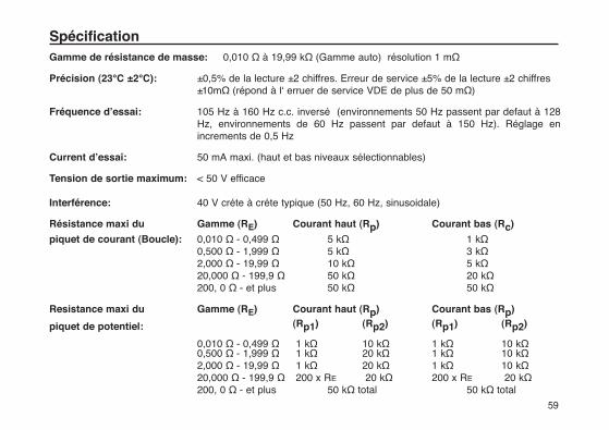
59
Gamme de résistance de masse: 0,010 Ω à 19,99 kΩ (Gamme auto) résolution 1 mΩ
Précision (23°C ±2°C): ±0,5% de la lecture ±2 chiffres. Erreur de service ±5% de la lecture ±2 chiffres ±10mΩ (répond à l‘ erruer de service VDE de plus de 50 mΩ)
Fréquence d’essai: 105 Hz à 160 Hz c.c. inversé (environnements 50 Hz passent par defaut à 128 Hz, environnements de 60 Hz passent par defaut à 150 Hz). Réglage en increments de 0,5 Hz
Current d’essai: 50 mA maxi. (haut et bas niveaux sélectionnables)
Tension de sortie maximum: < 50 V efficace
Interférence: 40 V créte à créte typique (50 Hz, 60 Hz, sinusoidale)
Résistance maxi du Gamme (RE) Courant haut (Rp) Courant bas (Rc)
piquet de courant (Boucle): 0,010 Ω - 0,499 Ω 5 kΩ 1 kΩ0,500 Ω - 1,999 Ω 5 kΩ 3 kΩ2,000 Ω - 19,99 Ω 10 kΩ 5 kΩ20,000 Ω - 199,9 Ω 50 kΩ 20 kΩ200, 0 Ω - et plus 50 kΩ 50 kΩ
Resistance maxi du Gamme (RE) Courant haut (Rp) Courant bas (Rp)
piquet de potentiel: (Rp1) (Rp2) (Rp1) (Rp2)
0,010 Ω - 0,499 Ω 1 kΩ 10 kΩ 1 kΩ 10 kΩ0,500 Ω - 1,999 Ω 1 kΩ 20 kΩ 1 kΩ 10 kΩ2,000 Ω - 19,99 Ω 1 kΩ 20 kΩ 1 kΩ 10 kΩ20,000 Ω - 199,9 Ω 200 x RE 20 kΩ 200 x RE 20 kΩ200, 0 Ω - et plus 50 kΩ total 50 kΩ total
Spécification
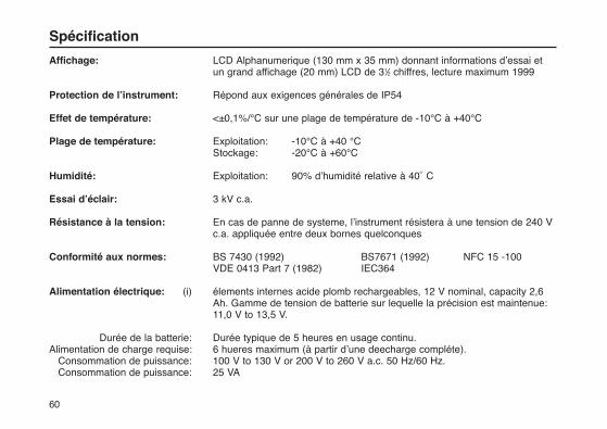
60
Affichage: LCD Alphanumerique (130 mm x 35 mm) donnant informations d’essai et un grand affichage (20 mm) LCD de 31⁄2 chiffres, lecture maximum 1999
Protection de l’instrument: Répond aux exigences générales de IP54
Effet de température: <±0,1%/°C sur une plage de température de -10°C à +40°C
Plage de température: Exploitation: -10°C à +40 °C Stockage: -20°C à +60°C
Humidité: Exploitation: 90% d’humidité relative à 40˚ C
Essai d’éclair: 3 kV c.a.
Résistance à la tension: En cas de panne de systeme, l’instrument résistera à une tension de 240 V c.a. appliquée entre deux bornes quelconques
Conformité aux normes: BS 7430 (1992) BS7671 (1992) NFC 15 -100VDE 0413 Part 7 (1982) IEC364
Alimentation électrique: (i) élements internes acide plomb rechargeables, 12 V nominal, capacity 2,6 Ah. Gamme de tension de batterie sur lequelle la précision est maintenue: 11,0 V to 13,5 V.
Durée de la batterie: Durée typique de 5 heures en usage continu.Alimentation de charge requise: 6 hueres maximum (à partir d’une deecharge compléte).
Consommation de puissance: 100 V to 130 V or 200 V to 260 V a.c. 50 Hz/60 Hz.Consommation de puissance: 25 VA
Spécification
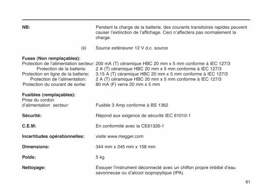
61
NB: Pendant la charge de la batterie, des courants transitoires rapides peuvent causer l’extinction de l’affichage. Ceci n’affectera pas normalement la charge.
(ii) Source extérieurer 12 V d.c. source
Fuses (Non remplaçables):Protection de l’alimentation secteur: 200 mA (T) céramique HBC 20 mm x 5 mm conforme à IEC 127/3
Protection de la batterie: 2 A (T) céramique HBC 20 mm x 5 mm conforme à IEC 127/3 Protection en ligne de la batterie: 3,15 A (T) céramique HBC 20 mm x 5 mm conforme à IEC 127/3
Protection de l’alimentation: 2 A (T) céramique HBC 20 mm x 5 mm conforme à IEC 127/3 Protection du courant de sortie: 80 mA (F) verre 20 mm x 5 mm
Fusibles (remplaçables):Prise du cordon d’alimentation secteur: Fusible 3 Amp conforme à BS 1362
Sécurité: Répond aux exigence de sécurité IEC 61010-1
C.E.M: En conformité avec la CE61326-1
Incertitudes opérationnelles: visite www.megger.com
Dimensions: 344 mm x 245 mm x 158 mm
Poids: 5 kg
Nettoyage: Essuyer l’instrument déconnecté avec un chiffon propre imbibé d’eau savonneuse ou d’alcool isopropylique (IPA).
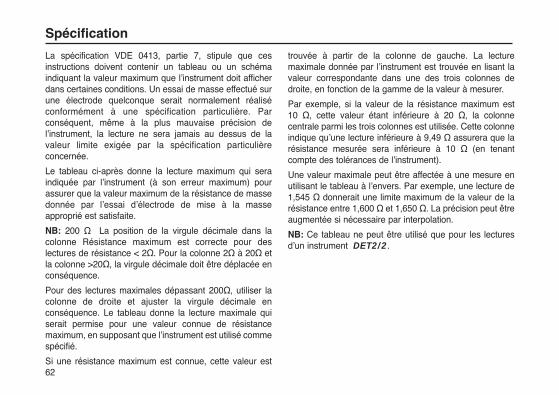
La spécification VDE 0413, partie 7, stipule que cesinstructions doivent contenir un tableau ou un schémaindiquant la valeur maximum que l’instrument doit afficherdans certaines conditions. Un essai de masse effectué surune électrode quelconque serait normalement réaliséconformément à une spécification particulière. Parconséquent, même à la plus mauvaise précision del’instrument, la lecture ne sera jamais au dessus de lavaleur limite exigée par la spécification particulièreconcernée.
Le tableau ci-après donne la lecture maximum qui seraindiquée par l’instrument (à son erreur maximum) pourassurer que la valeur maximum de la résistance de massedonnée par l’essai d’électrode de mise à la masseapproprié est satisfaite.
NB: 200 Ω La position de la virgule décimale dans lacolonne Résistance maximum est correcte pour deslectures de résistance < 2Ω. Pour la colonne 2Ω à 20Ω etla colonne >20Ω, la virgule décimale doit être déplacée enconséquence.
Pour des lectures maximales dépassant 200Ω, utiliser lacolonne de droite et ajuster la virgule décimale enconséquence. Le tableau donne la lecture maximale quiserait permise pour une valeur connue de résistancemaximum, en supposant que l’instrument est utilisé commespécifié.
Si une résistance maximum est connue, cette valeur est
trouvée à partir de la colonne de gauche. La lecturemaximale donnée par l’instrument est trouvée en lisant lavaleur correspondante dans une des trois colonnes dedroite, en fonction de la gamme de la valeur à mesurer.
Par exemple, si la valeur de la résistance maximum est 10 Ω, cette valeur étant inférieure à 20 Ω, la colonnecentrale parmi les trois colonnes est utilisée. Cette colonneindique qu’une lecture inférieure à 9,49 Ω assurera que larésistance mesurée sera inférieure à 10 Ω (en tenantcompte des tolérances de l’instrument).
Une valeur maximale peut être affectée à une mesure enutilisant le tableau à l’envers. Par exemple, une lecture de1,545 Ω donnerait une limite maximum de la valeur de larésistance entre 1,600 Ω et 1,650 Ω. La précision peut êtreaugmentée si nécessaire par interpolation.
NB: Ce tableau ne peut être utilisé que pour les lecturesd’un instrument DET2/2.
62
Spécification

63
Valuermaximum deresistance
< 2 > 20 2 to 20
Lecture maximale Valuermaximum deresistance < 2 > 20 2 to 20
Lecture maximale
0,050 -0,036 -
0,100 -0,083 -
0,150 -0,131 -
0,200 18,80,179 1,88
0,250 23,60,226 2,35
0,300 28,30,274 2,83
0,350 33,10,321 3,30
0,400 37,90,369 3,78
0,450 42,60,417 4,26
0,500 47,40,464 4,73
0,550 52,10,512 5,21
0,600 56,90,560 5,68
0,650 61,70,607 6,16
0,700 66,40,655 6,64
0,750 71,20,702 7,11
0,800 76,00,750 7,59
0,850 80,70,798 8,07
0,900 85,50,845 8,54
0,950 90,20,983 9,02
1,000 95,00,940 9,49
1,050 99,80,988 9,97
1,100 104,51,036 10,45
1,150 109,31,083 10,92
1,200 114,01,131 11,40
1,250 118,81,179 11,88
1,300 123,61,226 12,35
1,350 128,31,274 12,83
1,400 133,11,321 13,30
1,450 137,91,369 13,78
1,500 142,61,417 14,26
1,550 147,41,464 14,73
1,600 152,11,512 15,21
1,650 156,91,560 15,69
1,700 161,71,607 16,16
1,750 166,41,655 16,64
1,800 171,21,702 17,11
1,850 176,01,750 17,59
1,900 180,71,798 18,07
1,950 185,41,845 18,54
2,000 190,21,893 19,02
2,050 195,01,940 19,50
21,00 199,81,988 19,97
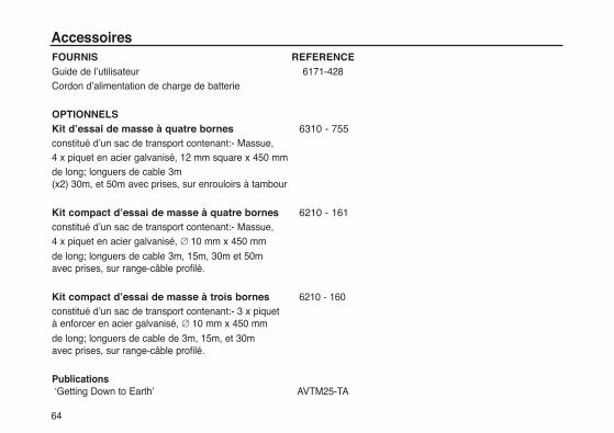
FOURNIS REFERENCEGuide de l’utilisateur 6171-428Cordon d’alimentation de charge de batterie
OPTIONNELSKit d’essai de masse à quatre bornes 6310 - 755constitué d’un sac de transport contenant:- Massue,4 x piquet en acier galvanisé, 12 mm square x 450 mm de long; longuers de cable 3m (x2) 30m, et 50m avec prises, sur enrouloirs à tambour
Kit compact d’essai de masse à quatre bornes 6210 - 161constitué d’un sac de transport contenant:- Massue,4 x piquet en acier galvanisé, ∅ 10 mm x 450 mm
de long; longuers de cable 3m, 15m, 30m et 50m avec prises, sur range-câble profilé.
Kit compact d’essai de masse à trois bornes 6210 - 160constitué d’un sac de transport contenant:- 3 x piquet à enforcer en acier galvanisé, ∅ 10 mm x 450 mm
de long; longuers de cable de 3m, 15m, et 30m avec prises, sur range-câble profilé.
Publications‘Getting Down to Earth’ AVTM25-TA
64
Accessoires
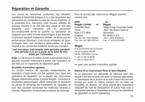
Les circuits de l’instrument contiennent des élémentssensibles à l’electricite statique et il y a lieu de prendre desprécautions en manipulant la carte de circuits imprimes. Sila protection d’un instrument s’est trouvee affectée dequelque maniére il ne doit pas être utilisé et doit êtreexpeedié pour réparation par du personnelconvenablement formé et qualifié. La protection del’appareil peut s’être trouvée endommagée si par exemplel’instrument apparaît visiblement abîmee, ne donne pas lesperformances attendues, s’est trouvé entreposé de façonprolongée dans des conditions défavorables ou a étéexposé a des contraintes extrêmes durant son transport.Les nouveaux instruments sont garantis pendant
une période d’un an à partir de la date de leurachat par l’utilisateur.
Note: Le fait d’ouvrir le boîtier annule automatique-ment lagarantie couvrant l’instrument à moins que l’opération nesoit faite par un organisme de réparation agréé.
Societés d’entretien agrééesUn certain nombre de sociétés indépendantes dereparation d’instruments ont êté agréées pour faire desopérations de réparation sur la plupart des instrumentsMegger utilisant des pièces d’origine Megger. Consultez ledistributeur désigné/agent officiel concernant la fourniturede pièces de rechange, les installations de réparation etpour être conseillé concernant les meilleures mesures àprendre. Réparation d’instruments et pièces de rechange
Pour le service des instruments Megger prendrecontact soit:
avec ouMegger Limited or MeggerArchcliffe Road Valley Forge Corporate CenterDover 2621 Van Buren AvenueKent CT17 9EN Norristown England PA 19403 U.S.A.Tél: 44+ (0) 1304 502243 Tél:+1 (610) 676-8579Fax: 44+ (0) 1304 207342 Fax: +1 (610) 676-8625
MeggerZ.A. Du Buisson de la Couldre 23 rue Eugène Henaff78190 TRAPPES FranceT +33 (1) 30.16.08.90F +33 (1) 34.61.23.77
ou avec une societe d’entretien agréée.
Renvoi D’un Instrument Pour le faire RéparerSi un instrument est réexpédiê au fabricant pour êtrereparé il doit être envoyé port payé a l’adresse appropriée.Un exemplaire de la facture et la note d’envoi doivent êtreenvoyé par avion au même moment afin de hâter lesformalités de douane. Un devis estimé des réparationsindiquant les frais de réexpedition et autres frais sera sinécessaire adressé a l’expéditeur avant que les opérationsde réparation ne soient enterprises.
Réparation et Garantie
65

66

M
DET2/2Digitaler Erdungsprüfer
Gebrauchsanleitung
67
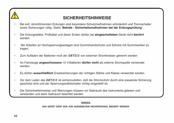
68
SICHERHEITSHINWEISE• Bei evtl. stromführenden Erdungen sind besondere Schutzmaßnahmen erforderlich und Trennschalter
sowie Sicherungen nötig. Siehe ’Betrieb - Sicherheitsmaßnahmen bei der Erdungsprüfung’.
• Die Erdungsstäbe, Prüfkabel und deren Enden dürfen bei eingeschaltetem Gerät nicht berührtwerden.
• Bei Arbeiten an Hochspannungsanlagen sind Gummihandschuhe und Schuhe mit Gummisohlen zutragen.
• Zum Aufladen der Batterien muß der DET2/2 von externen Stromkreisen getrennt werden.
• An Fahrzeuge angeschlossene 12 V-Batterien dürfen nicht als externe Stromquelle verwendetwerden.
• Es dürfen ausschließlich Ersatzsicherungen der richtigen Stärke und Klasse verwendet werden.
• Vor dem Laden des DET2/2 ist sicherzustellen, daß die Stromzufuhr durch eine passende Sicherunggeschützt wird und der Spannungswählschalter richtig eingestellt ist.
• Die Sicherheitshinweise und Warnungen müssen vor Gebrauch des Instruments gelesen undverstanden und beim Gebrauch beachtet werden.
HINWEIS
DAS GERÄT DARF NUR VON AUSGEBILTEM FACHPERSONAL BEDIENT WERDEN
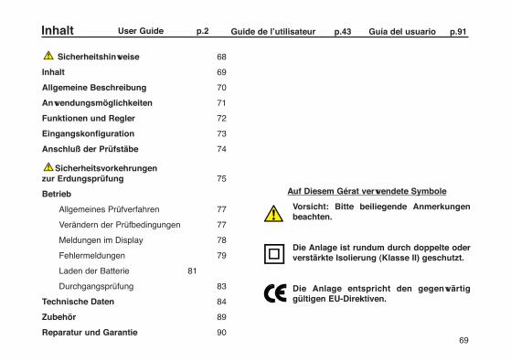
Sicherheitshinweise 68
Inhalt 69
Allgemeine Beschreibung 70
Anwendungsmöglichkeiten 71
Funktionen und Regler 72
Eingangskonfiguration 73
Anschluß der Prüfstäbe 74
Sicherheitsvorkehrungen zur Erdungsprüfung 75
Betrieb
Allgemeines Prüfverfahren 77
Verändern der Prüfbedingungen 77
Meldungen im Display 78
Fehlermeldungen 79
Laden der Batterie 81
Durchgangsprüfung 83
Technische Daten 84
Zubehör 89
Reparatur und Garantie 90
Auf Diesem Gérat verwendete Symbole
Vorsicht: Bitte beiliegende Anmerkungen beachten.
Die Anlage ist rundum durch doppelte oder verstärkte Isolierung (Klasse II) geschutzt.
Die Anlage entspricht den gegenwärtig gültigen EU-Direktiven.
Inhalt User Guide p.2 Guide de l’utilisateur p.43 Guía del usuario p.91
69

Megger DET2/2 ist ein in sich geschlossenes kompaktestragbares Instrument zur Messung des Widerstands vonErdungselektroden und für Durchgangsprüfungen mit vierAnschlüssen. Außerdem lassen sichErdungswiderstandsprüfungen zur Messung desspezifischen Bodenwiderstands durchführen. DasInstrument wird von einer aufladbaren Batterie im Gehäusemit integriertem Ladegerät mit Strom versorgt und nutzt alleVorteile der Mikroprozessortechnologie. Die Meßwertewerden auf einer großen digitalen Flüssigkristallanzeigedeutlich dargestellt. Das Gerät läßt sich über spezielleAnschlüsse auch an eine externe 12 V-Stromquelle wie z.B. eine Autobatterie anschließen.Die Meßwerte können wahweise in Englisch, Französisch,Deutsch, Portugiesisch oder Spanisch angezeigt werden.Es sind verschiedene Frequenzen wählbar. DET2/2verfügt über eine automatische Bereichsauswahl und zeigtden Erdungswiderstand im Bereich von 0,010 Ω bis 19,99kΩ mit einer Auflösung von bis zu 1 mW an. Die Anzeigeweist auf Probleme bei den Prüfbedingungen und aufniedrige Batteriespannung hin. Daraufhin können dieErdungsstäbe neu ausgerichtet oder das Instrumenteingestellt werden, um optimale Prüfbedingungensicherzustellen. Zum Anschalten des Geräts wird der rote Prüfknopf (TEST)gedrückt und anschließend zum Feststellen imUhrzeigersinn bis zur Position ON gedreht. ZumAusschalten wird der Prüfknopf gegen den Uhrzeigersinn
gedreht und losgelassen.Die LCD-Anzeige läßt sich über die Konstrasttaste an diejeweiligen Lichtbedingungen anpassen.Die Meßfunktion wird über vier verschiedeneMembranschalter (die mit ▲ oder ▼ markiert sind) geregelt.Über diese Schalter lassen sich auch die Sprache und diePrüfeinstellungen bestimmen.Die Prüfkabel werden nicht mit dem Gerät geliefert,sondern gehören zu einem Zubehörsatz zurErdungsprüfung, der auf Wunsch erhältlich ist. Zu diesemSatz gehören auch Prüfstäbe (Elektroden) zum Herstellenvon vorübergehenden Erdungsstäben.Das Gerät ist in einem robusten und widerstandsfähigenGehäuse aus ABS-Plastik untergebracht. Alle Regler,Anschlüsse und das LCD-Display sind an derVorderkonsole angebracht. DET2/2 ist spritzwassersicherund eignet sich für den Außeneinsatz unter praktisch allenWetterbedingungen. Der Anschluß ’C2’ (’H’) dient zum Anschluß des externenPrüfstabs für Stromstärke.Der Anschluß ‘P2‘ (’S’) dient zum Anschluß des externenPrüfstabs für Potential.Der Anschluß ’P1’ (’ES’) dient zum Anschluß desPotentials an die zu prüfende Erdungselektrode.
Der Anschluß ’C1’ (’E’) dient zum Anschluß derStromstärke an die zu prüfende Erdungselektrode.
Allgemeine Beschreibung
70

Die Installation funktionsfähiger Erdungsvorrichtungengehört zu den unverzichtbaren Bestandteilen vonStromversorgungs-,Verkabelungs-und Installationsarbeiten.Auch bei zahlreichen Fernmeldeanlagen spielt sie einebedeutende Rolle.Die wichtigste Anwendugn des DET2/2 besteht in derPrüfung von Erdungselektroden, von einzelnen undMehrfachelektroden bis hin zu Maschennetzen undErdungsblechen oder -streifen. Alle Erdungsvorrichtungenmüssen sofort nach Einbau und anschließend inregelmäßigen Abständen geprüft werden.
Standort der ElektrodeFür eine zuverlässige Funktion darf eineErdungselektrodenvorrichtung stets nur einen geringenGesamtwiderstand zur Erde besitzen. Dieser Wertverändert sich mit dem spezifischen Widerstand desUmgebungsbodens. Dieser Widerstand hängt wiederumvon der Beschaffenheit und dem Feuchtigkeitsgehalt desBodens ab. Vor der Auswahl des Standorts, an dem dieElektrode oder die Elektrodenvorrichtung eingegrabenwerden soll, ist es daher oft sinnvoll, die Umgebung nachgünstigen Stellen abzusuchen. Mit DET2/2 läßt sich derspezifische Bodenwiderstand eines bestimmten Bereichesan der Oberfläche und in verschiedenen Tiefen bestimmen.Durch diese Widerstandsmessungen läßt sich ermitteln, obsich durch tieferes Hineinstecken der Elektroden ein Vorteilerzielen läßt und sich auf diese Weise zusätzliche Kosten
für weitere Elektroden und Kabel zum Erreichen desvorgeschriebenen Gestamtwiderstands derErdungsvorrichtung vermeiden lassen.
Wartung der Erdungsvorrichtungen Nach dem Einbau einer Erdungsvorrichtung läßt sichüberprüfen, ob sich der spezifische Widerstand mit der Zeitbzw. bei unterschiedlicher Bodenfeuchtigkeit (z. B.aufgrund veränderter Wetterbedingungen oderjahreszeitlicher Unterschiede) nennenswert ändert. Durchsolche Prüfungen läßt sich ermitteln, ob der Widerstand derErdelektrode zur Erde hin durch veränderteBodenbedingungen oder Alterserscheinungen zu großgeworden ist.
Sonstige AnwendungenFür archäologische und geologische Zwecke läßt sich derBoden anhand seines spezifischen Widerstands inverschiedenen Tiefen auf Struktur und Gebäuderesteuntersuchen. Die Genauigkeit der Instrumentenanzeige liegt in allenFällen höher als die Abweichungen durch natürlicheVeränderungen der Bodenbeschaffenheit.Eine weitere Einsatzmöglichkeit besteht in derDurchgängigkeitsprüfung, z. B. zum Prüfen desLeiterwiderstands in einem Erdungsstromkreis.
Anwendungsmöglichkeiten
71

72
Funktionen und Regler
Zur geprüften Elektrode (Potentialanschluß)
Zur geprüften Elektrode(Stromstärkenanschluß)
Ladebuchse
Anschluß für externe 12 V-
Stromversorgung
Einstellung des Anzeigenkontrastes
Zum Prüfstab für PotentialZum Prüfstab für Stromstärke
Prüftaste Ein/Aus(zum Feststellen im Uhrzeigersinn
drehen)
LCD mit 31⁄2 Stellen
Schalter zurPrüfsteuerung
Einstellung der StandardspracheDie Standardsprache der Anzeige läßt sich wie folgtwählen:1. Drücken Sie gleichzeitig die linke Taste ▲ und die
Prüftaste (mit der Beschriftung ‘TEST‘). Wenn Sie nun die Prüftaste im Uhrzeigersinn in die arretierte Stellung drehen, werden die wählbaren Sprachen angezeigt.
2. Stellen Sie ggf. den Bilschirmkontrast ein.
3. Wählen Sie die gewünschte Sprache mit der mittleren Taste ▲. Die gewählte Taste wird durch einen Rahmen hervorgehoben. Drücken Sie zur Bestätigung die linke Taste ▲. Anschließend werden die wählbaren Prüffrequenzen angezeigt.
Einstellung der StandardfrequenzEs sind die folgenden Standardfrequenzen verfügbar:
108 Hz - Für Prüfungen bei sich überlagernden Frequenzen im Bereich von 16 Hz.
128 Hz - Für Prüfungen bei sich überlagernden Frequenzen im Bereich von 50 Hz.
135 Hz -
150 Hz - Für Prüfungen bei sich überlagernden Frequenzen im Bereich von 60 Hz.
Für jeden Standardwert läßt sich derStandardfrequenzbereich mit den Tasten ▲ und ▲ inSchritten von je 0,5 Hz von 105 bis auf 160 Hz erhöhen.
Die Standardfrequenz wird wie folgt gewählt undeingestellt:1. Mit der mittleren Taste ▲ können Sie die
verschiedenen Frequenzen aufrufen. Wenn die gewünschte Frequenz durch einen Rahmen hervorgehoben wird, drücken Sie zur Bestätigung die linke Taste ▲. Anschließend werden die Prüf- und Kalibrieroptionen angezeigt, und es erscheint die Meldung "Bitte warten...".
Speichern der gewählten PrüfparameterDie Einstellungen für den Prüfstrom und zum Filtern sowiedie Frequenz des Prüfstroms lassen sich für späterePrüfungen wie folgt speichern:1. Wenn Sie alle Einstellungen vorgenommen haben,
drücken Sie die Auswahltaste ▲ im Meßmodus und halten Sie sie fest. Auf der Anzeige erscheint die Standardauswahl.
2. Bestätigen Sie die Einstellungen mit der Taste Ja ▲ oder unterbrechen Sie mit der Taste Nein ▲.
Nach der Bestätigung können auf Wunsch weiterePrüfungen mit abweichenden Einstellungen vorgenommenwerden. Sobald das Gerät aus- und wieder eingeschaltetwird, werden die gespeicherten Standardeinstellungen
Eingangskonfiguration
73
Zur Prüfung der Erdungselektroden und des spezifischenErdungswiderstands werden die Prüfkabel des Gerätes andie Stäbe angeschlossen, die wiederum in den Bodengesteckt werden. Wie die Anschlüsse vorgenommenwerden, hängt davon ab, welche Art von Prüfungdurchgeführt werden soll. Einzelheiten siehe unter‘Meßtechniken’.
Prüfstäbe und lange Prüfkabel werden bei allenErdungsprüfungen benötigt. Die Grundausstattung ist indem als Zubehör erhältlichen Erdungsprüfsatz enthalten(siehe ’Zubehör’).
1. Stecken Sie den Prüfstab für Stromstärke 30 bis 50 Meter von der zu prüfenden Erdungselektrode entfernt in den Boden.
2. Schließen Sie diesen Stab an den Instrumentenanschluß ’C2’ (’H’) an.
3. Stecken Sie den Prüfstab für Potential in der Mitte der gedachten Geraden zwischen dem Prüfstab für Stromstärke und der Erdungselektrode in den Boden.
4. Schließen Sie diesen Stab an den Instrumentenanschluß ’P2’ (’S’) an.
5. Achten Sie beim Verlegen der Prüfkabel zu den externen Elektroden darauf, daß die Kabel nicht zu
nahe beieinander verlaufen.
Anschluß der Prüfstäbe
74
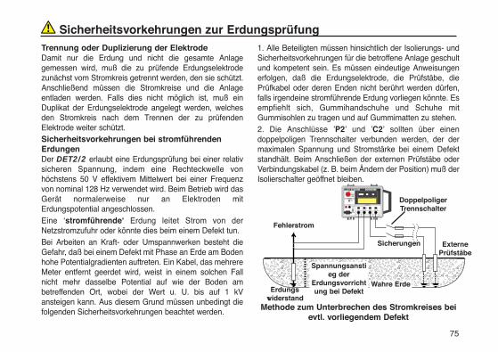
75
Trennung oder Duplizierung der ElektrodeDamit nur die Erdung und nicht die gesamte Anlagegemessen wird, muß die zu prüfende Erdungselektrodezunächst vom Stromkreis getrennt werden, den sie schützt.Anschließend müssen die Stromkreise und die Anlageentladen werden. Falls dies nicht möglich ist, muß einDuplikat der Erdungselektrode angelegt werden, welchesden Stromkreis nach dem Trennen der zu prüfendenElektrode weiter schützt. Sicherheitsvorkehrungen bei stromführendenErdungenDer DET2/2 erlaubt eine Erdungsprüfung bei einer relativsicheren Spannung, indem eine Rechteckwelle vonhöchstens 50 V effektivem Mittelwert bei einer Frequenzvon nominal 128 Hz verwendet wird. Beim Betrieb wird dasGerät normalerweise nur an Elektroden mitErdungspotential angeschlossen.Eine ‘stromführende‘ Erdung leitet Strom von derNetzstromzufuhr oder könnte dies beim einem Defekt tun.Bei Arbeiten an Kraft- oder Umspannwerken besteht dieGefahr, daß bei einem Defekt mit Phase an Erde am Bodenhohe Potentialgradienten auftreten. Ein Kabel, das mehrereMeter entfernt geerdet wird, weist in einem solchen Fallnicht mehr dasselbe Potential auf wie der Boden ambetreffenden Ort, wobei der Wert u. U. bis auf 1 kVansteigen kann. Aus diesem Grund müssen unbedingt diefolgenden Sicherheitsvorkehrungen beachtet werden.
1. Alle Beteiligten müssen hinsichtlich der Isolierungs- undSicherheitsvorkehrungen für die betroffene Anlage geschultund kompetent sein. Es müssen eindeutige Anweisungenerfolgen, daß die Erdungselektrode, die Prüfstäbe, diePrüfkabel oder deren Enden nicht berührt werden dürfen,falls irgendeine stromführende Erdung vorliegen könnte. Esempfiehlt sich, Gummihandschuhe und Schuhe mitGummisohlen zu tragen und auf Gummimatten zu stehen.2. Die Anschlüsse ’P2’ und ’C2’ sollten über einendoppelpoligen Trennschalter verbunden werden, der dermaximalen Spannung und Stromstärke bei einem Defektstandhält. Beim Anschließen der externen Prüfstäbe oderVerbindungskabel (z. B. beim Ändern der Position) muß derIsolierschalter geöffnet bleiben.
Methode zum Unterbrechen des Stromkreises beievtl. vorliegendem Defekt
Sicherheitsvorkehrungen zur Erdungsprüfung
������������������������������������Erdungs
widerstand
Doppelpoliger Trennschalter
Wahre Erde
Sicherungen ExternePrüfstäbe
Spannungsanstieg der
Erdungsvorrichtung bei Defekt
Fehlerstrom

Sicherheitsvorkehrungen zur Erdungsprüfung
76
Falls sich keine Trennschalter verwenden lassen, müssendie Kabel vor Berühren der externen Stäbe und Kabel vomGerät getrennt werden. Wenn die externen Anschlüssevorgenommen worden sind, müssen die Endanschlüsseam Gerät mit isolierten Steckern erfolgen, wobei derBediener geeignete und ausreichendeSicherheitsvorkehrungen wie z. B. Isoliermatten,Gummihandschuhe usw. zu treffen hat.
Tritt bei einer Prüfung ein Defekt auf, so kann das Gerät zuSchaden kommen. Sicherungen am Trennschalter (von 100mA, die der maximalen Fehlerspannung standhalten)bieten einen gewissen Schutz für das Instrument.
Vorsicht: Bei Arbeiten an stromführenden Orten darf dasGerät nicht über eine externe Batterie mit Strom versorgtwerden, da sonst auch diese bei einem Defekt unter Stromgesetzt werden kann.
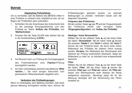
77
Allgemeines PrüfverfahrenUm zu vermeiden, daß die Batterie des DET2/2 mitten ineiner Prüfreihe zu schwach wird, empfiehlt es sich, sie vorBeginn der Prüfarbeiten ganz aufzuladen.1. Schließen Sie die Anschlüsse des Instruments fest
an die jeweilige Erdungselektrode und den Prüfstab an. Siehe ’Aufbau der Prüfstäbe’ und ’Meßtechniken’.
2. Drücken Sie die Taste On/Off oder drehen Sie sie in die Arretierstellung (LOCK).
3. Auf Wunsch kann zur Prüfung der Durchgängigkeit
des Potentialkreises eine Pspitze-Prüfung durchgeführt werden.
4. Auf dem Unterdisplay erscheint die Meldung "Bitte warten...", die nach einigen Sekunden vom gemessenen Widerstandswert abgelöst wird.
Verändern der PrüfbedingungenWenn im Unterdisplay eine Meldung erscheint, daß keinegenaue Messung durchgeführt werden kann, können die
Prüfbedingungen geändert werden, um optimaleBedingungen zu erzielen. Verändern lassen sich diefolgenden Parameter:Frequenz des PrüfstromsMit den rechten Tasten ▲ oder ▼ wird der Frequenzbereichdes Prüfstroms erhöht oder verringert. Siehe’Eingangskonfiguration’ und ’Aufbau der Prüfstäbe’.
Niedrige / hohe StromstärkeWählen Sie mit der mittleren Taste ▲ auf der linken Seitedie Option "Stromstärke". Mit der linken Taste ▲ könnenSie zwischen ”Neider I” und ”Hoch I” wählen. Mit ”Hoch I”können Sie evtl. Probleme lösen, die durch einen hohenWiderstand des Prüfstabs bei starkem Strom erzeugtwerden. Hinweis: Der Widerstand des Stromkreises wirdwährend der Prüfung kontinuierlich überwacht. Steigt derWiderstand zu stark an, so erscheint eine entsprechendeNachricht.FilterWählen Sie mit der mittleren Taste ▲ auf der linken Seitedie Option ’Filter’. Mit der linken Taste ▲ können Siezwischen ’Filter aus’ und ’Filter ein’ wählen. Mit ’Filter ein’lassen sich Störfrequenzen beim Ablesen der Werteweitgehend reduzieren. Allerdings steigt die für dieMessung benötigte Zeit bei Verwendung des Filterserheblich an.
Betrieb
Prüfstab-PotentialWählen Sie mit der mittleren Taste ▲ auf der linken Seitedie Option ”Pspitze”. Mit der linken Taste ▲ führen Sieautomatisch eine Widerstandprüfung des Potentialkreisesdurch. Nach einer kurzen Pause wird das Ergebnis derÜberprüfung auf dem Unterdisplay angezeigt. Ggf. wirdstatt ”Pspitze” anschließend "Neu testen" angezeigt, umnach Veränderung der Position des Prüfstabs o. ä. diePrüfung zu wiederholen. Zur Wiederholung desMeßvorgangs wird die mittlere Taste gedrückt, die nun mit"Messen" beschriftet ist. Hinweis: Wenn eine Prüfung aus irgendeinem Grund miteinem offenen Potentialkreis durchgeführt wird, ist dasangezeigte Testergebnis ungültig. Um sicherzustellen, daßsich alle Anschlüsse weiter an ihrem Platz befinden und diePrüfung gültig ist, sollte eine Prüfung ”Pspitze” vor jedemPrüfvorgang durchgeführt werden.
Automatische BereichsauswahlWird ein zu geringer Erdungswiderstand gemessen undsind zugleich viele Störfrequenzen und ein hoherWiderstand des Prüfstabs vorhanden, wird automatischeine Messung mit geringerer Präzision vorgenommen. Beierfolgreich verlaufener Prüfung wird der Widerstandswertnur mit drei Ziffern angezeigt und die letzte Zifferausgelassen. Die Präzision läßt sich wie folgt erhöhen:a) Verringerung des Stabwiderstands (z. B., indem
der Boden befeuchtet oder die Stäbe tiefer in den
Boden geschoben werden).
b) Wählen der Option ”Hoch I”
c) Falls möglich, Ausschalten der Ursache der Störfrequenzen.
Meldungen im DisplayIm Display können verschiedene Meldungen erscheinen,die die folgenden Bedeutungen besitzen:
"Bitte warten...""Bitte warten... Nullstellung"
Diese Meldungen bedeuten, daß das Instrument vor derAnzeige des gemessenen Widerstands interne Messungenund Prüfungen vornimmt. Die Tasten ▲ und ▼ könnenweiterhin verwendet werden, so daß sich diePrüfbedingungen vor der Anzeige des Meßwerts ändernlassen. Die Meldungen können wiederholt erscheinen,wenn starke Störfrequenzen im Bereich der Meßfrequenzvorliegen oder der Potentialkreis falsch angeschlossen ist.
"Stromkreis an Stromanschlüssen unterbrochen"
Diese Meldung bedeutet, daß ein sehr schwacherPrüfstrom fließt und zwischen den Prüfanschlüssen einWiderstand von mehr als 500 kΩ vorliegt. Wenn dieseMeldung auch beim Kurzschließen der Anschlüsse ’C1’ und’C2’ nicht verschwindet, ist eine Sicherung durchgebrannt,wobei auch andere Beschädigungen im Geräteinnerenaufgetreten sein können. In diesem Fall senden Sie dasGerät bitte an den Hersteller oder eine autorisierte
Betrieb
78
Reparaturwerkstatt. Siehe ’Reparatur und Garantie’.
"Spannungklemmen Auschlüsse Prüfen"
Diese Meldung erscheint, wenn die Anschlüsse für ’P1’ und’P2’ vertauscht wurden. Überprüfen Sie die Anschlüsse undnehmen Sie ggf. Korrekturen vor.
"Hohe Strom Fremdspannung"
"Hoh Spannungs Fremdspannung"
Diese Meldung erscheinen, wenn die Geräuschspannunghöher ist als für eine gültige Messung zulässig. In einemsolchen Fall führt ein Ändern der Prüffrequenz zu keinerAbhilfe. Falls möglich, sollten Sie die Ursache derStörfrequenzen beheben oder den Widerstand desPrüfstabes verringern (z. B., indem Sie den Bodenbefeuchten oder die Stäbe tiefer in den Boden schieben).
Weitere DisplaymeldungenBei starken Interferenzen oder einem Gerätedefekt könnenim Display die folgenden Meldungen erscheinen:
"Ungültige Strommanzeige"
"Ungültige Spannungzeige"
"Ungültiger Strom-Null"
"Ungültiger Spannungs-Null"
"Spannungs-Null zu Groß"
"Strom-Null zu Groß "
"Fremdspannungsbehaftete Strom-Null"
"Fremdspannungsbehaftete Spannungs-Null"
Bei einem falschen Anschluß der Potentialverbindungenkann die Meldung "Ungültige Spannung" erscheinen.
FehlermeldungenBei einem Fehler des Gerätes oder der Software bzw. beielektrischen Störungen erscheint in der unteren Zeile desBildschirms eine Fehlermeldung. Wenn eineFehlermeldung erscheint, schalten Sie den DET2/2 aus,konsultieren Sie das Kapitel "Reparatur und Garantie" undsenden Sie das Gerät unter Angabe der Fehlermeldungund der Softwareversion an den Hersteller oder eineautorisierte Reparaturwerkstatt.
"Calibration data retrieval error
Auf handbuch bezug nehmen"
Wenn die im Gerät gespeicherten Kalibrierdaten nichtrichtig aufgerufen werden können, erscheint beimEinschalten (auf Englisch) die obenstehende Meldung.Schalten Sie den DET2/2 aus, konsultieren Sie dasKapitel "Reparatur und Garantie" und senden Sie dasGerät unter Angabe der Fehlermeldung und derSoftwareversion an den Hersteller oder eine autorisierteReparaturwerkstatt.
79
"Setup data retrieval error"
Beim Einschalten des Gerätes werden normalerweise dieStandarddaten für Sprache, Frequenz und Stromstärkeaufgerufen. Wenn dies nicht möglich ist, wird beim Einschalten die
obenstehende Meldung (auf Englisch) angezeigt.Gleichzeitig erscheinen die Optionen "Wiederhol" (um dasAufrufen der Daten erneut zu versuchen) und "Manuell"(um die Daten manuell erneut einzugeben). Wenn derFehler weder über "Wiederhol" noch über "Manuell"behoben werden kann, schalten Sie den DET2/2 aus,konsultieren Sie das Kapitel "Reparatur und Garantie" undsenden Sie das Gerät unter Angabe der Fehlermeldungund der Softwareversion an den Hersteller oder eineautorisierte Reparaturwerkstatt.
Betrieb
80
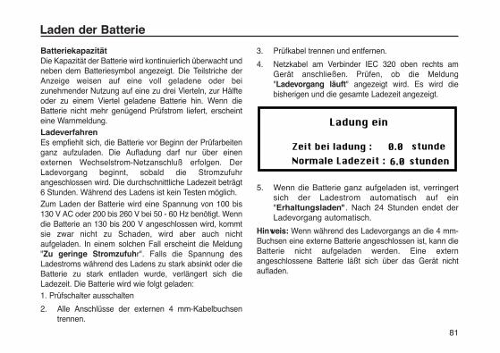
81
BatteriekapazitätDie Kapazität der Batterie wird kontinuierlich überwacht undneben dem Batteriesymbol angezeigt. Die Teilstriche derAnzeige weisen auf eine voll geladene oder beizunehmender Nutzung auf eine zu drei Vierteln, zur Hälfteoder zu einem Viertel geladene Batterie hin. Wenn dieBatterie nicht mehr genügend Prüfstrom liefert, erscheinteine Warnmeldung. LadeverfahrenEs empfiehlt sich, die Batterie vor Beginn der Prüfarbeitenganz aufzuladen. Die Aufladung darf nur über einenexternen Wechselstrom-Netzanschluß erfolgen. DerLadevorgang beginnt, sobald die Stromzufuhrangeschlossen wird. Die durchschnittliche Ladezeit beträgt6 Stunden. Während des Ladens ist kein Testen möglich.Zum Laden der Batterie wird eine Spannung von 100 bis130 V AC oder 200 bis 260 V bei 50 - 60 Hz benötigt. Wenndie Batterie an 130 bis 200 V angeschlossen wird, kommtsie zwar nicht zu Schaden, wird aber auch nichtaufgeladen. In einem solchen Fall erscheint die Meldung"Zu geringe Stromzufuhr". Falls die Spannung desLadestroms während des Ladens zu stark absinkt oder dieBatterie zu stark entladen wurde, verlängert sich dieLadezeit. Die Batterie wird wie folgt geladen:1. Prüfschalter ausschalten
2. Alle Anschlüsse der externen 4 mm-Kabelbuchsen trennen.
3. Prüfkabel trennen und entfernen.
4. Netzkabel am Verbinder IEC 320 oben rechts am Gerät anschließen. Prüfen, ob die Meldung "Ladevorgang läuft" angezeigt wird. Es wird die bisherigen und die gesamte Ladezeit angezeigt.
5. Wenn die Batterie ganz aufgeladen ist, verringert sich der Ladestrom automatisch auf ein "Erhaltungsladen". Nach 24 Stunden endet der Ladevorgang automatisch.
Hinweis: Wenn während des Ladevorgangs an die 4 mm-Buchsen eine externe Batterie angeschlossen ist, kann dieBatterie nicht aufgeladen werden. Eine externangeschlossene Batterie läßt sich über das Gerät nichtaufladen.
Laden der Batterie

Kabelstecker zum BatterieladenWenn sich der Kabelstecker nicht für Ihre Steckdose eignet,verwenden Sie keinen Adapter, sondern besorgen Sie sichein passendes Ladekabel oder schneiden Sie ggf. denalten Stecker ab (Kabel vorher von Stromquelle trennen)und ersetzen Sie ihn durch ein passendes Modell.
Die farbliche Kennzeichnung des Kabels ist die folgende:
Erde (Masse) - Gelb-Grün
Neutral - Blau
Phase (Strom) - Braun
Bei Verwendung eines Steckers mit Sicherung muß eineSicherung von 3 A nach BS 1362 benutzt werden.
Hinweis: Wenn Sie einen Stecker vom Stromkabelabschneiden, machen Sie ihn bitte unbrauchbar - dieblanken Kabel können beim Anschluß an einestromführende Steckdose lebensgefährlich sein.
Hinweise zum Laden der Batterie1) Entladen Sie die Batterie nicht vollständig. Wenn
das Gerät über längere Zeit nicht benutzt wird,laden
Sie die Batterie mindestens alle 6 Monate auf (bei Lagertemperaturen von mehr als 40 °C häufiger).
2) Das Laden der Batterie sollte in einer trockenen Umgebung und bei Temperaturen zwischen 0 und 40 °C erfolgen.
3) Beim Aufladen in geschlossenen Räumen sollte derRaum gut belüftet werden.
Laden der Batterie
82
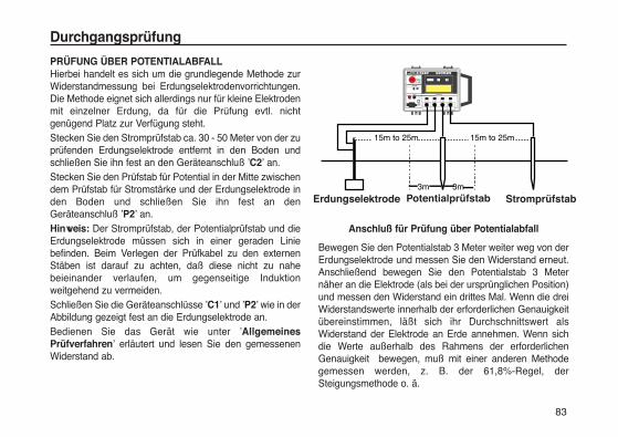
83
Durchgangsprüfung
PRÜFUNG ÜBER POTENTIALABFALLHierbei handelt es sich um die grundlegende Methode zurWiderstandmessung bei Erdungselektrodenvorrichtungen.Die Methode eignet sich allerdings nur für kleine Elektrodenmit einzelner Erdung, da für die Prüfung evtl. nichtgenügend Platz zur Verfügung steht.Stecken Sie den Stromprüfstab ca. 30 - 50 Meter von der zuprüfenden Erdungselektrode entfernt in den Boden undschließen Sie ihn fest an den Geräteanschluß ’C2’ an. Stecken Sie den Prüfstab für Potential in der Mitte zwischendem Prüfstab für Stromstärke und der Erdungselektrode inden Boden und schließen Sie ihn fest an denGeräteanschluß ’P2’ an. Hinweis: Der Stromprüfstab, der Potentialprüfstab und dieErdungselektrode müssen sich in einer geraden Liniebefinden. Beim Verlegen der Prüfkabel zu den externenStäben ist darauf zu achten, daß diese nicht zu nahebeieinander verlaufen, um gegenseitige Induktionweitgehend zu vermeiden. Schließen Sie die Geräteanschlüsse ’C1’ und ’P2’ wie in derAbbildung gezeigt fest an die Erdungselektrode an.Bedienen Sie das Gerät wie unter ’AllgemeinesPrüfverfahren’ erläutert und lesen Sie den gemessenenWiderstand ab.
Anschluß für Prüfung über Potentialabfall
Bewegen Sie den Potentialstab 3 Meter weiter weg von derErdungselektrode und messen Sie den Widerstand erneut.Anschließend bewegen Sie den Potentialstab 3 Meternäher an die Elektrode (als bei der ursprünglichen Position)und messen den Widerstand ein drittes Mal. Wenn die dreiWiderstandswerte innerhalb der erforderlichen Genauigkeitübereinstimmen, läßt sich ihr Durchschnittswert alsWiderstand der Elektrode an Erde annehmen. Wenn sichdie Werte außerhalb des Rahmens der erforderlichenGenauigkeit bewegen, muß mit einer anderen Methodegemessen werden, z. B. der 61,8%-Regel, derSteigungsmethode o. ä.
Electrode�under test
Potential �spike
3m 3m
15m to 25m 15m to 25m
�Current�spike
Erdungselektrode Potentialprüfstab Stromprüfstab
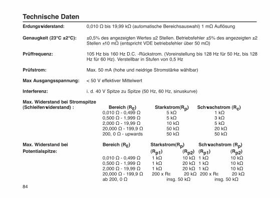
84
Erdungswiderstand: 0,010 Ω bis 19,99 kΩ (automatische Bereichsauswahl) 1 mΩ Auflösung
Genaugkeit (23°C ±2°C): ±0,5% des angezeigten Wertes ±2 Stellen. Betriebsfehler ±5% des angezeigten ±2 Stellen ±10 mΩ (entspricht VDE betriebsfehler über 50 mΩ)
Prüffrequenz: 105 Hz bis 160 Hz D.C. -Rückstrom. (Voreinstellung bis 128 Hz für 50 Hz, bis 128 Hz für 60 Hz). Verstellbar in Stufen von 0,5 Hz
Prüfstrom: Max. 50 mA (hohe und neidrige Stromstärke wählbar)
Max Ausgangsspannung: < 50 V effektiver Mittelwert
Interferenz: i. d. 40 V Spitze zu Spitze (50 Hz, 60 Hz, sinuskurve)
Max. Widerstand bei Stromspitze (Schleifenwiderstand) : Bereich (RE) Starkstrom(Rp) Schwachstrom (Rc)
0,010 Ω - 0,499 Ω 5 kΩ 1 kΩ0,500 Ω - 1,999 Ω 5 kΩ 3 kΩ2,000 Ω - 19,99 Ω 10 kΩ 5 kΩ20,000 Ω - 199,9 Ω 50 kΩ 20 kΩ200, 0 Ω - upwards 50 kΩ 50 kΩ
Max. Widerstand bei Bereich (RE) Starkstrom(Rp) Schwachstrom (Rp)Potentialspitze: (Rp1) (Rp2) (Rp1) (Rp2)
0,010 Ω - 0,499 Ω 1 kΩ 10 kΩ 1 kΩ 10 kΩ0,500 Ω - 1,999 Ω 1 kΩ 20 kΩ 1 kΩ 10 kΩ2,000 Ω - 19,99 Ω 1 kΩ 20 kΩ 1 kΩ 10 kΩ20,000 Ω - 199,9 Ω 200 x RE 20 kΩ 200 x RE 20 kΩab 200, 0 Ω insg. 50 kΩ insg. 50 kΩ
Technische Daten
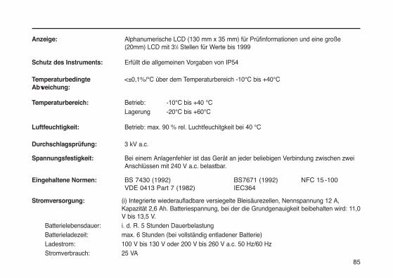
85
Anzeige: Alphanumerische LCD (130 mm x 35 mm) für Prüfinformationen und eine große (20mm) LCD mit 31⁄2 Stellen für Werte bis 1999
Schutz des Instruments: Erfüllt die allgemeinen Vorgaben von IP54
Temperaturbedingte <±0,1%/°C über dem Temperaturbereich -10°C bis +40°CAbweichung:
Temperaturbereich: Betrieb: -10°C bis +40 °C Lagerung -20°C bis +60°C
Luftfeuchtigkeit: Betrieb: max. 90 % rel. Luchtfeuchitgkeit bei 40 °C
Durchschlagsprüfung: 3 kV a.c.
Spannungsfestigkeit: Bei einem Anlagenfehler ist das Gerät an jeder beliebigen Verbindung zwischen zwei Anschlüssen mit 240 V a.c. belastbar.
Eingehaltene Normen: BS 7430 (1992) BS7671 (1992) NFC 15 -100VDE 0413 Part 7 (1982) IEC364
Stromversorgung: (i) Integrierte wiederaufladbare versiegelte Bleisäurezellen, Nennspannung 12 A, Kapazität 2,6 Ah. Batteriespannung, bei der die Grundgenauigkeit beibehalten wird: 11,0 V bis 13,5 V.
Batterielebensdauer: i. d. R. 5 Stunden DauerbelastungBatterieladezeit: max. 6 Stunden (bei vollständig entladener Batterie)Ladestrom: 100 V bis 130 V oder 200 V bis 260 V a.c. 50 Hz/60 HzStromverbrauch: 25 VA
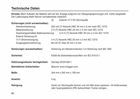
86
Hinweis: Beim Aufladen der Batterie wird auf der Anzeige aufgrund von Übergangsspannungen evtl. nichts dargestellt.Der Ladevorgang bleibt hiervon normalerweise unberührt.
(ii) Externe 12 V DC-StromquelleSicherungen (nicht auswechselbar):
Netzstromsicherung: 200 mA (T) Keramik HBC 20 mm x 5 mm nach IEC 127/3 Batteriesicherung: 2 A (T) Keramik HBC 20 mm x 5 mm nach IEC 127/3 Zwischengeschaltete Batteriesicherung: 3,15 A (T) Keramik HBC 20 mm x 5 mm IEC 127/3 Externe Sicherung für 12 V Stromversorgung: 2 A (T) Keramik HBC 20 mm x 5 mm IEC 127/3 Ausgangsstromsicherung: 80 mA (F) Glas 20 mm x 5 mm
Sicherungen (auswechselbar): Sicherung am Netzstromstecker: 3 A Sicherung nach BS 1362
Sicherheit: Erfüllt die Sicherheitsvorschriften von IEC 61010-1
Elektromagnetische Verträglichkeit: Gemäss IEC61326-1
Betriebliche Unklarheiten: Besuch www.megger.com
Maße: 344 mm x 245 mm x 158 mm
Gewicht: 5 kg
Reinigung: Gerät von Stromquelle trennen und mit Hilfe eines sauberen, mit Seifenwasser oder Isopropylalkohol (IPA) befeuchteten Tuches reinigen.
Technische Daten

Nach VDE 0413, Teil 7 muß diese Gebrauchsanweisungeine Tabelle oder ein Diagramm mit den Höchstwertenenthalten, die das Instrument unter bestimmtenBedingungen anzeigen muß. Eine Erdungsprüfung an einerElektrodenvorrichtung würde normalerweise nach einerbestimmten Spezifikation erfolgen. Daher liegt die Anzeigeselbst bei der ungenauesten Meßweise des Gerätes nieüber dem Grenzwert der jeweiligen Spezifikation.
Die umseitige Tabelle enthält den höchsten Wert, der vomInstrument (bei maximalem Fehler) angezeigt wird, umsicherzustellen, daß der von den Prüfspezifikationen für diejeweilige Erdungselektrode vorgegebene Höchstwert desErdungswiderstandes eingehalten wird.
Hinweis: Die Dezimalstelle in der Spalte mit denHöchstwiderstandswerten bezieht sich aufWiderstandswerte von < 2 Ω. Für die Spalten 2 Ω, 20 Ω und< 2 Ω. muß die Dezimalstelle entsprechend verschobenwerden. Bei Höchstanzeigen von mehr als 200 Ω ist dierechte Spalte zu verwenden und die Dezimalstelleentsprechend zu verschieben.
Die Tabelle liefert den höchsten Wert, der bei einervorschriftsmäßigen Verwendung des Instruments für einenbekannten Höchstwiderstandswert angezeigt werden darf.
Wenn der Höchstwiderstand bekannt ist, kann dieser Wertanhand der linken Spalte gefunden werden. DieHöchstanzeige des Instruments befindet sich je nach Höhedes gemessenen Wertes in einer der rechten drei Spalten.
Wenn z. B. der Höchstwiderstand 10 Ω beträgt, wird diemittlere der drei Spalten verwendet, da der Wert unter 20 Ωliegt. Aus dieser Spalte geht hervor, daß bei einer Anzeigevon 9,49 Ω der gemessene Widerstand unterBerücksichtigung der Gerätetoleranzen bei unter 10 Ω liegt.
Der Höchstwert für eine Messung läßt sich ermitteln, indemdie Tabelle umgekehrt verwendet wird. Wenn z. B. ein Wertvon 1,545 Ω angezeigt wird, liegt die Höchstgrenze desWiderstandswertes zwischen 1,600 Ω und 1,650 Ω. DieGenauigkeit läßt sich bei Bedarf durch Interpolationerhöhen.
Hinweis: Diese Tabelle bezieht sich nur auf Messungen mitDET2/2.
87
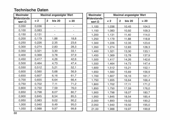
88
MaximalerWiderstands-
wert Ω < 2 > 20 2 bis 20
Maximal angezeigter Wert MaximalerWiderstands-
wert Ω < 2 > 20 2 bis 20
Maximal angezeigter Wert
0,050 -0,036 -
0,100 -0,083 -
0,150 -0,131 -
0,200 18,80,179 1,88
0,250 23,60,226 2,35
0,300 28,30,274 2,83
0,350 33,10,321 3,30
0,400 37,90,369 3,78
0,450 42,60,417 4,26
0,500 47,40,464 4,73
0,550 52,10,512 5,21
0,600 56,90,560 5,68
0,650 61,70,607 6,16
0,700 66,40,655 6,64
0,750 71,20,702 7,11
0,800 76,00,750 7,59
0,850 80,70,798 8,07
0,900 85,50,845 8,54
0,950 90,20,983 9,02
1,000 95,00,940 9,49
1,050 99,80,988 9,97
1,100 104,51,036 10,45
1,150 109,31,083 10,92
1,200 114,01,131 11,40
1,250 118,81,179 11,88
1,300 123,61,226 12,35
1,350 128,31,274 12,83
1,400 133,11,321 13,30
1,450 137,91,369 13,78
1,500 142,61,417 14,26
1,550 147,41,464 14,73
1,600 152,11,512 15,21
1,650 156,91,560 15,69
1,700 161,71,607 16,16
1,750 166,41,655 16,64
1,800 171,21,702 17,11
1,850 176,01,750 17,59
1,900 180,71,798 18,07
1,950 185,41,845 18,54
2,000 190,21,893 19,02
2,050 195,01,940 19,50
21,00 199,81,988 19,97
Technische Daten
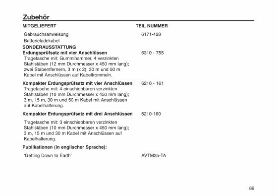
MITGELIEFERT TEIL NUMMER
Gebrauchsanweisung 6171-428Batterieladekabel
SONDERAUSSTATTUNGErdungsprüfsatz mit vier Anschlüssen 6310 - 755Tragetasche mit: Gummihammer, 4 verzinkten Stahlstäben (12 mm Durchmesser x 450 mm lang);zwei Stabentfernern, 3 m (x 2), 30 m und 50 m Kabel mit Anschlüssen auf Kabeltrommeln.
Kompakter Erdungsprüfsatz mit vier Anschlüssen 6210 - 161Tragetasche mit: 4 einschiebbaren verzinkten Stahlstäben (10 mm Durchmesser x 450 mm lang); 3 m, 15 m, 30 m und 50 m Kabel mit Anschlüssen auf Kabelhalterung.
Kompakter Erdungsprüfsatz mit drei Anschlüssen 6210-160
Tragetasche mit: 3 einschiebbaren verzinkten Stahlstäben (10 mm Durchmesser x 450 mm lang); 3 m, 15 m und 30 m Kabel mit Anschlüssen auf Kabelhalterung.
Publikationen (in englischer Sprache):
‘Getting Down to Earth’ AVTM25-TA
89
Zubehör
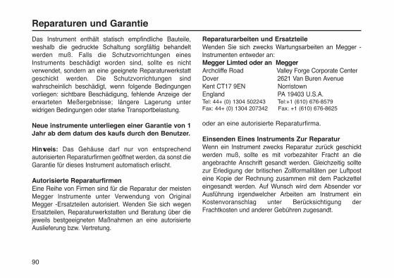
Das Instrument enthält statisch empfindliche Bauteile,weshalb die gedruckte Schaltung sorgfältig behandeltwerden muß. Falls die Schutzvorrichtungen einesInstruments beschädigt worden sind, sollte es nichtverwendet, sondern an eine geeignete Reparaturwerkstattgeschickt werden. Die Schutzvorrichtungen sindwahrscheinlich beschädigt, wenn folgende Bedingungenvorliegen: sichtbare Beschädigung, fehlende Anzeige dererwarteten Meßergebnisse; längere Lagerung unterwidrigen Bedingungen oder starke Transportbelastung.
Neue instrumente unterliegen einer Garantie von 1Jahr ab dem datum des kaufs durch den Benutzer.
Hinweis: Das Gehäuse darf nur von entsprechendautorisierten Reparaturfirmen geöffnet werden, da sonst dieGarantie für dieses Instrument automatisch erlischt.
Autorisierte ReparaturfirmenEine Reihe von Firmen sind für die Reparatur der meistenMegger lnstrumente unter Verwendung von OriginalMegger -Ersatzteilen autorisiert. Wenden Sie sich wegenErsatzteilen, Reparaturwerkstatten und Beratung über diejeweils bestgeeigneten Maßnahmen an eine autorisierteAuslieferung bzw. Vertretung.
Reparaturarbeiten und ErsatzteileWenden Sie sich zwecks Wartungsarbeiten an Megger -lnstrumenten entweder an:Megger Limted oder an MeggerArchcliffe Road Valley Forge Corporate CenterDover 2621 Van Buren AvenueKent CT17 9EN Norristown England PA 19403 U.S.A.Tel: 44+ (0) 1304 502243 Tel:+1 (610) 676-8579Fax: 44+ (0) 1304 207342 Fax: +1 (610) 676-8625
oder an eine autorisierte Reparaturfirma.
Einsenden Eines Instruments Zur ReparaturWenn ein Instrument zwecks Reparatur zurück geschicktwerden muß, sollte es mit vorbezahiter Fracht an dieangebrachte Anschrift gesandt werden. Gleichzeitig solltezur Erledigung der britischen Zollformalitäten per Luftposteine Kopie der Rechnung zusammen mit dem Packzetteleingesandt werden. Auf Wunsch wird dem Absender vorAusführung irgendwelcher Arbeiten am Instrument einKostenvoranschlag unter Berücksichtigung derFrachtkosten und anderer Gebühren zugesandt.
Reparaturen und Garantie
90
91
M
DET2/2Probador de Puesta a tierradigital
Guía del usuario
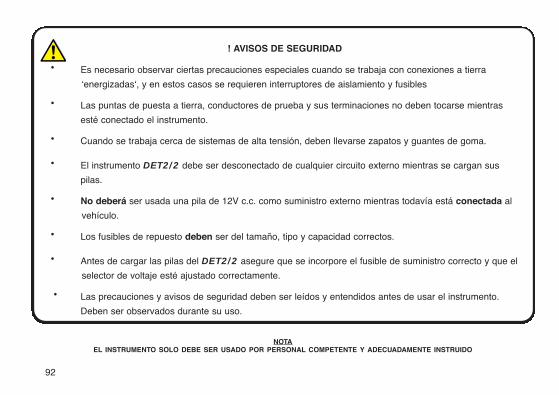
92
! AVISOS DE SEGURIDAD
· Es necesario observar ciertas precauciones especiales cuando se trabaja con conexiones a tierra
‘energizadas‘, y en estos casos se requieren interruptores de aislamiento y fusibles
· Las puntas de puesta a tierra, conductores de prueba y sus terminaciones no deben tocarse mientras
esté conectado el instrumento.
· Cuando se trabaja cerca de sistemas de alta tensión, deben llevarse zapatos y guantes de goma.
· El instrumento DET2/2 debe ser desconectado de cualquier circuito externo mientras se cargan sus
pilas.
· No deberá ser usada una pila de 12V c.c. como suministro externo mientras todavía está conectada al
vehículo.
· Los fusibles de repuesto deben ser del tamaño, tipo y capacidad correctos.
· Antes de cargar las pilas del DET2/2 asegure que se incorpore el fusible de suministro correcto y que el
selector de voltaje esté ajustado correctamente.
· Las precauciones y avisos de seguridad deben ser leídos y entendidos antes de usar el instrumento.
Deben ser observados durante su uso.
NOTAEL INSTRUMENTO SOLO DEBE SER USADO POR PERSONAL COMPETENTE Y ADECUADAMENTE INSTRUIDO
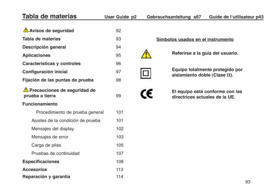
93
Avisos de seguridad 92
Tabla de materias 93
Descripción general 94
Aplicaciones 95
Características y controles 96
Configuración inicial 97
Fijación de las puntas de prueba 98
Precauciones de seguridad de prueba a tierra 99
Funcionamiento
Procedimiento de prueba general 101
Ajustes de la condición de prueba 101
Mensajes del display 102
Mensajes de error 103
Carga de pilas 105
Pruebas de continuidad 107
Especificaciones 108
Accesorios 113
Reparación y garantía 114
Símbolos usados en el instrumento
Referirse a la guía del usuario.
Equipo totalmente protegido por aislamiento doble (Clase II).
El equipo está conforme con las directrices actuales de la UE.
Tabla de materias User Guide p2 Gebrauchsanleitung s67 Guide de l‘utilisateur p43
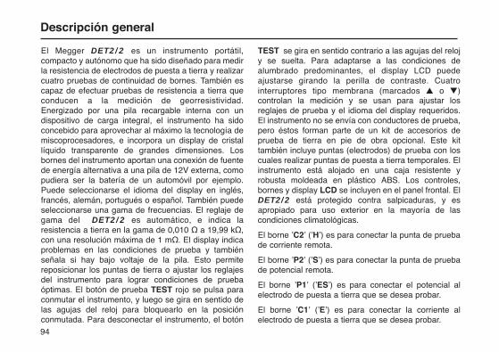
94
El Megger DET2/2 es un instrumento portátil,compacto y autónomo que ha sido diseñado para medirla resistencia de electrodos de puesta a tierra y realizarcuatro pruebas de continuidad de bornes. También escapaz de efectuar pruebas de resistencia a tierra queconducen a la medición de georresistividad.Energizado por una pila recargable interna con undispositivo de carga integral, el instrumento ha sidoconcebido para aprovechar al máximo la tecnología demiscoprocesadores, e incorpora un display de cristallíquido transparente de grandes dimensiones. Losbornes del instrumento aportan una conexión de fuentede energía alternativa a una pila de 12V externa, comopudiera ser la batería de un automóvil por ejemplo.Puede seleccionarse el idioma del display en inglés,francés, alemán, portugués o español. También puedeseleccionarse una gama de frecuencias. El reglaje degama del DET2/2 es automático, e indica laresistencia a tierra en la gama de 0,010 Ω a 19,99 kΩ,con una resolución máxima de 1 mΩ. El display indicaproblemas en las condiciones de prueba y tambiénseñala si hay bajo voltaje de la pila. Esto permitereposicionar los puntas de tierra o ajustar los reglajesdel instrumento para lograr condiciones de pruebaóptimas. El botón de prueba TEST rojo se pulsa paraconmutar el instrumento, y luego se gira en sentido delas agujas del reloj para bloquearlo en la posiciónconmutada. Para desconectar el instrumento, el botón
TEST se gira en sentido contrario a las agujas del relojy se suelta. Para adaptarse a las condiciones dealumbrado predominantes, el display LCD puedeajustarse girando la perilla de contraste. Cuatrointerruptores tipo membrana (marcados ▲ o ▼)controlan la medición y se usan para ajustar losreglajes de prueba y el idioma del display requeridos.El instrumento no se envía con conductores de prueba,pero éstos forman parte de un kit de accesorios deprueba de tierra en pie de obra opcional. Este kittambién incluye puntas (electrodos) de prueba con loscuales realizar puntas de puesta a tierra temporales. Elinstrumento está alojado en una caja resistente yrobusta moldeada en plástico ABS. Los controles,bornes y display LCD se incluyen en el panel frontal. ElDET2/2 está protegido contra salpicaduras, y esapropiado para uso exterior en la mayoría de lascondiciones climatológicas.
El borne ’C2’ (’H’) es para conectar la punta de pruebade corriente remota.
El borne ’P2’ (’S’) es para conectar la punta de pruebade potencial remota.
El borne ’P1’ (’ES’) es para conectar el potencial alelectrodo de puesta a tierra que se desea probar.
El borne ’C1’ (’E’) es para conectar la corriente alelectrodo de puesta a tierra que se desea probar.
Descripción general
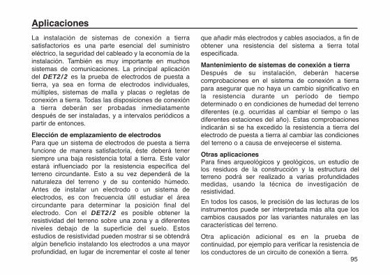
95
La instalación de sistemas de conexión a tierrasatisfactorios es una parte esencial del suministroeléctrico, la seguridad del cableado y la economía de lainstalación. También es muy importante en muchossistemas de comunicaciones. La principal aplicacióndel DET2/2 es la prueba de electrodos de puesta atierra, ya sea en forma de electrodos individuales,múltiples, sistemas de malla y placas o regletas deconexión a tierra. Todas las disposiciones de conexióna tierra deberán ser probadas inmediatamentedespués de ser instaladas, y a intervalos periódicos apartir de entonces.
Elección de emplazamiento de electrodosPara que un sistema de electrodos de puesta a tierrafuncione de manera satisfactoria, éste deberá tenersiempre una baja resistencia total a tierra. Este valorestará influenciado por la resistencia específica delterreno circundante. Esto a su vez dependerá de lanaturaleza del terreno y de su contenido húmedo.Antes de instalar un electrodo o un sistema deelectrodos, es con frecuencia útil estudiar el áreacircundante para determinar la posición final delelectrodo. Con el DET2/2 es posible obtener laresistividad del terreno sobre una zona y a diferentesniveles debajo de la superficie del suelo. Estosestudios de resistividad pueden mostrar si se obtendráalgún beneficio instalando los electrodos a una mayorprofundidad, en lugar de incrementar el coste al tener
que añadir más electrodos y cables asociados, a fin deobtener una resistencia del sistema a tierra totalespecificada.
Mantenimiento de sistemas de conexión a tierraDespués de su instalación, deberán hacersecomprobaciones en el sistema de conexión a tierrapara asegurar que no haya un cambio significativo enla resistencia durante un período de tiempodeterminado o en condiciones de humedad del terrenodiferentes (e.g. ocurridas al cambiar el tiempo o lasdiferentes estaciones del año). Estas comprobacionesindicarán si se ha excedido la resistencia a tierra delelectrodo de puesta a tierra al cambiar las condicionesdel terreno o a causa de envejecerse el sistema.
Otras aplicacionesPara fines arqueológicos y geológicos, un estudio delos residuos de la construcción y la estructura delterreno podrá ser realizado a varias profundidadesmedidas, usando la técnica de investigación deresistividad.
En todos los casos, le precisión de las lecturas de losinstrumentos puede ser interpretada más alta que loscambios causados por las variantes naturales en lascaracterísticas del terreno.
Otra aplicación adicional es en la prueba decontinuidad, por ejemplo para verificar la resistencia delos conductores de un circuito de conexión a tierra.
Aplicaciones
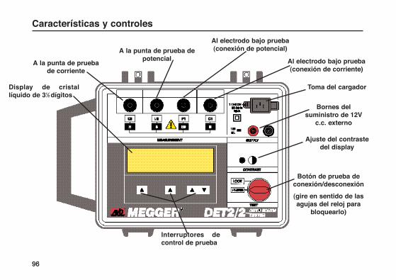
9696
Características y controles
Al electrodo bajo prueba (conexión de potencial)
Al electrodo bajo prueba(conexión de corriente)
Toma del cargador
Bornes delsuministro de 12V
c.c. externo
Ajuste del contrastedel display
A la punta de prueba depotencial
A la punta de prueba de corriente
Botón de prueba deconexión/desconexión
(gire en sentido de lasagujas del reloj para
bloquearlo)
Display de cristallíquido de 31⁄2 dígitos
Interruptores decontrol de prueba

97
Reglaje del idioma por defectoSeleccione y luego fije el idioma del display comosigue:
1. Pulse la tecla izquierda ▲ y el botón TEST(prueba) conjuntamente. Gire el botón TEST en sentido de las agujas del reloj para bloquearlo. Los idiomas opcionales son visualizados.
2. Ajuste el contraste del display según convenga.
3. Usando la tecla central ▲, desplácese por los idiomas opcionales. Al quedar resaltado con un marco el idioma requerido, pulse le tecla izquierda ▲. Las frecuencias de prueba opcionales son visualizadas.
Reglaje de la frecuencia por defectoSe ofrecen disponibles las frecuencias de prueba pordefecto siguientes:
108 Hz - Para uso cuando se prueba con frecuencias de interferencia cercanas a 16Hz
128 Hz - Para uso cuando se prueba con frecuencias de interferencia cercanas a 50Hz
135 Hz -
150 Hz - Para uso cuando se prueba con frecuencias de interferencia cercanas a 60Hz
Para cada valor por defecto, la gama de frecuencias de
prueba puede incrementarse en pasos de 0,5 Hz de105 Hz a 160 Hz, usando las teclas ▲ ▼.
Seleccione y fije la frecuencia por defecto comosigue:1. Usando la tecla central s, desplácese por las
frecuencias opcionales. Al quedar resaltada con un marco la frecuencia requerida, pulse le teclaizquierda ▲. Los modos de prueba y calibración opcionales son visualizados. Se visualiza el mensaje “Por favor espera...”.
Para almacenar los reglajes de parámetros depruebaLos reglajes realizados para el filtrado y corriente de
prueba opcionales, así como la frecuencia de lacorriente de prueba pueden ser almacenados para serusados en pruebas ulteriores como sigue:
1. Después de hacer los reglajes, pulse y retenga la tecla de desplazamiento s durante el modo de medición. El display muestra las selecciones por defecto.
2. Acepte los reglajes y pulse la tecla Sí ▲, o la tecla No ▲ para cancelar.
Una vez aceptados los reglajes, podrán hacerse otraspruebas con reglajes diferentes si se desea. Elinstrumento pasará por defecto a los reglajesalmacenados si se desconecta y conecta de nuevo.
Configuración inicial

Para la prueba de electrodos de puesta a tierra y elestudio de resistividad a tierra, los conductores deprueba del instrumento se conectan a puntasinsertadas en el suelo. El modo en que se hacen lasconexiones depende del tipo de prueba realizada y losdetalles se incluyen en ’Técnicas de medición’
Son necesarias puntas de prueba y conductores deprueba largos para todos los tipos de pruebas de tierrarealizados y los kits de accesorios de prueba de tierraen pie de obra contienen los equipos básicos. Vea‘Accesorios‘.
1. Inserte la punta de prueba de corriente en el suelo a una distancia de 30 a 60 metros del electrodo de puesta a tierra que se desea probar.
2. Conecte esta punta al borne del instrumento ‘C2‘ (‘H‘).
3. Inserte la punta de prueba de potencial en el suelo a mitad de camino entre la punta de prueba de corriente y el electrodo de puesta a tierra, y en línea directa con ambas de ellas.
4. Conecte esta punta al borne del instrumento ’P2’ (’S’).
5. Cuando se tienden los conductores de prueba hasta cada electrodo remoto, evite disponer los cables demasiado cercanos unos a otros.
98
Fijación de las puntas de prueba
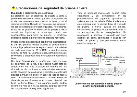
99
Duplicado o aislamiento de electrodosEs preferible que el electrodo de puesta a tierra aprobar sea aislado del circuito que está protegiendo, demodo que solamente sea medida la tierra y no elsistema completo. Cuando se hace esto, los circuitos ylos equipos deberán ser desenergizados. No obstante,si ello no es posible, el electrodo de puesta a tierradeberá ser duplicado, de modo que cuando seadesconectado para fines de prueba, el electrododuplicado aporte la protección de circuitos necesaria.
Precauciones de seguridad con tierras ‘energizadas’El DET2/2 permite realizar pruebas de puesta a tierraa un voltaje relativamente seguro usando un máximode onda cuadrada de 50 V RMS a una frecuencianominal de 128 Hz. Cuando se usa, normalmente sólose conecta a electrodos que incorporan un potencial atierra. Una tierra ’energizada’ es aquélla que porta corrientedel suministro de la red, o que podría hacer esto encondiciones de fallo. Cuando se trabaja en losalrededores de centrales o subcentrales eléctricas,existe el peligro de producirse gradientes de potencialgrandes a través del suelo en caso de fallo de fase atierra. Un cable conectado a tierra a muchos metros dedistancia no tendrá entonces el mismo potencial quetiene la tierra local, y en algunos casos podríaascender a más de 1 kV. Es esencial así pues observarlas precauciones de seguridad siguientes:
1. Todo el personal involucrado deberá estar capacitado y ser competente en los procedimientos de seguridad aplicables al sistema en que se trabaja. Deberá indicarse a este personal que no deberá tocar el electrodo de puesta a tierra, puntas de prueba, conductores de prueba o sus terminaciones si se encuentras tierras ’energizadas’. Se recomienda al personal involucrado que lleve guantes de goma apropiados y calzado con suela de goma y que permanezca sobre esterillas de goma.
Un método de desconexión cuando puedenocurrir condiciones de fallo.
Precauciones de seguridad de prueba a tierra
������������������������������������Resistencia a tierra
Interruptor de aislamiento
Tierra efectiva
Fusibles
Puntasremotas
Ascenso del voltajedel sistema depuesta a tierra encondiciones de fallo
Corrientede fallo

100
Precauciones de seguridad de prueba a tierra2. Los bornes ’P2’ y ’C2’ deberán ser conectados a
través de un interruptor de aislamiento bipolar capaz de resistir la corriente y el voltaje de fallo máximos. El interruptor de aislamiento deberá estar abierto mientras se hace cualquier contacto personal con puntas de prueba remotas o conductores de conexión, como por ejemplo cuando se cambia su posición.
Si no es posible usar interruptores de aislamiento, losconductores deberán ser desconectados delinstrumento antes de que puedan ser manejados éstosy las puntas remotas. Una vez hechas las conexionesremotas, las conexiones finales deberán hacerse alinstrumento usando tapones aislados, y asegurandoque el operador adopte todas las precaucionesapropiadas y adecuadas, tales como usar esterillasaislantes, guantes de goma, etc.
El instrumento puede resultar dañado si ocurre un fallomientras se está haciendo una prueba. Se aportarácierta medida de protección al instrumentoincorporando fusibles (de 100 mA y capaces de resistirel máximo voltaje de fallo) en el interruptor deaislamiento.
Precaución: Cuando se trabaja en lugaresenergizados, no debe utilizarse una pila exterior paraimpulsar el instrumento, ya que ésta también seenergizaría en condiciones de fallo.
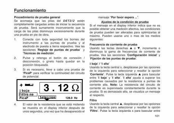
101
Procedimiento de prueba generalSe aconseja que las pilas del DET2/2 esténcompletamente cargadas antes de iniciar la secuenciade prueba. Será sumamente inconveniente que lacarga de las pilas disminuya excesivamente duranteuna prueba en pie de obra.
1. Conecte con toda seguridad los bornes del instrumento a las puntas de prueba y al electrodo de puesta a tierra respectivo. Vea las secciones ’Reglaje de puntas de prueba’ y ’Técnicas de medición’.
2. Pulse y retenga el botón de conexión / desconexión, o gírelo hasta quedar en la posición bloqueada.
3. Si es necesario, lleve a cabo una prueba de ‘PicaP‘ para verificar la continuidad del circuito de potencial.
4. El valor de la resistencia que se está midiendo se muestra en el display inferior después de unos segundos, una vez que ha desaparecido el
mensaje “Por favor espera ...”.
Ajustes de la condición de pruebaSi el mensaje en el display inferior indica que no esposible obtener una medición efectiva, las condicionesde prueba pueden ser alteradas para optimizarlas almáximo. Pueden usarse uno o mas de los mediossiguientes:
Frecuencia de corriente de pruebaUsando las teclas derechas ▲ o ▼, incremente odisminuya la gama de frecuencias de corriente deprueba. Vea las secciones ’Configuración inicial’ y’Fijación de las puntas de prueba’.
I baja’ / ‘I alta’Usando la tecla central s, desplácese por las opcionesde la izquierda para seleccionar y resaltar la opción’Corriente’. Pulse la tecla izquierda ▲ para bascularentre ’I baja’ y ‘I alta’. ‘I alta’ ayuda a superar losproblemas causados por la resistencia a puntas decorriente alta. Nota: La resistencia del circuito decorriente es supervisada constantemente durante laprueba. Si es demasiado alta, se visualiza un mensajeal respecto.
FiltroUsando la tecla central ▲, desplácese por las opcionesde la izquierda para seleccionar y resaltar la opción‘Filtro’. Pulse la tecla izquierda s para bascular entre
Funcionamiento
”Filtro no” y “Filtro si”. “Filtro si” ayuda a reducir el‘ruido’ que afecta la lectura. El tiempo invertido enrealizar una medición aumenta considerablemente con’Filtro si’.
PicaPUsando la tecla central ▲, desplácese por las opcionesde la izquierda para seleccionar y resaltar la opción“PicaP”. Pulse la tecla izquierda ▲ para realizarautomáticamente una prueba de resistencia delcircuito de potencial. Después de una corta pausa, elresultado de esta prueba es visualizado en el panelinferior. Si es apropiado, el nombre “PicaP” cambiaentonces a “Reensayer” (repetir prueba), ofreciendo laopción de repetir la prueba después de que se harealizado cualquier alteración en la posición de lapunta, etc. Pulse la tecla central ▲, ahora marcada“Medida”, para repetir la medición.
Nota: Si por cualquier motivo se hace una prueba conun circuito potencial abierto, le lectura de pruebaresultante será inválida. Para confirmar que lasconexiones todavía están en su sitio y para verificar lavalidez de la prueba, deberá hacerse unacomprobación de “PicaP“ antes de cada prueba.
Reglaje de gama automáticoSi la resistencia a tierra que se está midiendo es baja,pero existe un alto nivel de ’ruido’, aunado a unaresistencia de punta de corriente alta, el instrumento
realizará automáticamente una medición con unaprecisión más baja. Si tiene éxito, le lectura de laresistencia será visualizada con sólo 3 dígitos, siendoborrado el dígito de menor significación.
Podrá lograrse mayor precisión:
a) Reduciendo la resistencia de la punta (e.g. humedeciendo el terreno, o insertando las puntas a mayor profundidad).
b) Basculando a la opción de “I alta”.
c) Eliminando la fuente de ’ruidos’ si es posible.
Mensajes del displaySe visualizan mensajes en los casos apropiados.También se ofrecen las definiciones de mensajessiguientes:
“Por favor espera...”
“Por favor espera... Ajustadora Cero”
Esto significa que el instrumento está haciendopruebas y mediciones internas antes de visualizar lalectura de resistencia. Las teclas ▲ y ▼ permanecenactivas y las condiciones de medición puedenajustarse antes de visualizarse la lectura. Estosmensajes pueden visualizarse repetidamente si existeun alto nivel de ’ruidos’, cercano a la frecuencia de lamedición, o si el circuito de potencial está
102
Funcionamiento
incorrectamente conectado.
“Bornes de corriente en circuito abierto”
Esto significa que el flujo de corriente de prueba esbajo, dando a entender que existe una resistencia de>500 kΩ entre los bornes de prueba. Si este mensajepermanece visualizado cuando se cortocircuitan enconjunto los bornes ’C1’ y ’C2’, se habrá fundido unfusible interno, con la posibilidad de haberse causadootro daño interno. En este caso, devuelva elinstrumento al fabricante o a una firma de reparaciónaprobada. Vea la sección ’Reparación y Garantía’.
“Comprobación de las conexiones P”
Este mensaje se visualiza cuando se invierten lasconexiones a las conexiones ’P1’ y ’P2’. Compruebe ycorrija según sea necesario.
“Ruido de corriente Alta”
“Ruido de Tensión Alto”
Estos mensajes se visualizan cuando el voltaje deruido existente es superior al del nivel aceptable,causando la invalidez de la medición. Cambiando lafrecuencia de la prueba no se ejercerá ningún efectoen este caso. Si es posible, elimine el origen del ruido,o reduzca la resistencia de la punta (e.g.humedeciendo el terreno, o insertando las puntas amayor profundidad).
Otros mensajes del displayUn alto nivel de interferencia u otro fallo delinstrumento podría causar la visualización de unocualquiera de los mensajes siguientes:
“Lectura de corriente no válida”
“Lectura de Tensión no válida”
“Corriente cero inválida”
“Tensión cero inválida”
“Corriente cero demasiado alto”
“Tensión cero demasiado alto”
“Corriente de ruido cero”
“Tensión de ruido cero”
La conexión incorrecta de bornes de potencial podríacausar un mensaje de “Tension no válida”.
Mensajes de errorEn caso de fallar el software o el instrumento, o debidoa la existencia de condiciones eléctricas adversas,pueden aparecer en la línea inferior del displaymensajes de error. Si aparece un mensaje de error,desconecte el DET2/2, consulte la sección’Reparación y Garantía’ y devuelva el instrumento alfabricante o a su agente autorizado, incluyendodetalles del mensaje de error y la edición del software.
103
“Calibration data retrieval error (Error de recuperación de datos de calibración) Referirse al Manual”
Si los datos de calibración almacenados en elinstrumento han sido recuperados incorrectamente, sevisualiza (en inglés) el mensaje arriba ilustrado alhacer la conexión. Desconecte el DET2/2, consulte lasección ’Reparación y Garantía’ y devuelva elinstrumento al fabricante o a su agente autorizado,incluyendo detalles del mensaje de error y la edicióndel software.
“Setup Data Retrieval error“ (Error de recuperación de datos de reglaje)
El idioma por defecto, el nivel de corriente y lafrecuencia son normalmente recuperados cuando seconmuta el instrumento.
Si esto no ocurre, se visualiza (en inglés) el mensajearriba ilustrado cuando se conmuta, con la opción“Retry” (trate de leer los datos de nuevo) o “Manual”(fije manualmente los datos de nuevo). Si no tiene éxito“Retry” o “Manual”, desconecte el DET2/2, consultela sección ’Reparación y Garantía’ y devuelva elinstrumento al fabricante o a su agente autorizado,incluyendo detalles del mensaje de error y la edicióndel software.
104
Funcionamiento
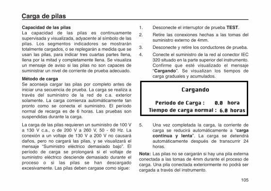
105
Capacidad de las pilasLa capacidad de las pilas es continuamentesupervisada y visualizada, adyacente al símbolo de laspilas. Los segmentos indicadores se mostrarántotalmente cargados, o se replegarán a medida que seusan las pilas, para indicar tres cuartas partes llena,llena por la mitad y completamente llena. Se visualizaun mensaje de aviso si las pilas no son capaces desuministrar un nivel de corriente de prueba adecuado.
Método de cargaSe aconseja cargar las pilas por completo antes deiniciar una secuencia de prueba. La carga se realiza através del suministro de la red de c.a. exteriorsolamente. La carga comienza automáticamente tanpronto como se conecta el suministro. El períodonormal de recarga es de 6 horas. Las pruebas sonsuspendidas durante la carga.
La carga de las pilas requieren un suministro de 100 Va 130 V c.a., o de 200 V a 260 V, 50 - 60 Hz. Laconexión a un voltaje de 130 V a 200 V no causarádaños, pero no cargará las pilas, y se visualizará elmensaje “Suministro eléctrico demasiado bajo”. Elperíodo de carga se prolongará si el voltaje desuministro eléctrico desciende demasiado durante elproceso o si las pilas se han descargadoexcesivamente. Las pilas deben cargase como sigue:
1. Desconecte el interruptor de prueba TEST.
2. Retire las conexiones hechas a las tomas del suministro externo de 4mm.
3. Desconecte y retire los conductores de prueba.
4. Conecte el suministro de la red al conector IEC 320 situado en la parte superior del instrumento. Confirme que esté visualizado el mensaje “Cargando”. Se visualizan los tiempos de carga graduales y acumulados.
5. Una vez completada la carga, la corriente de carga se reducirá automáticamente a “carga continua y lenta”. La carga se detendrá automáticamente después de transcurrir 24 horas.
Nota: Las pilas no se cargarán si hay una pila externaconectada a las tomas de 4mm durante el proceso decarga. Una pila conectada exteriormente no podrá sercargada a través del instrumento.
Carga de pilas
Enchufe del cable eléctrico de carga de pilasSi el enchufe del cable eléctrico no es adecuado parasu tipo de toma, no use un adaptador. Deberá usar uncable eléctrico alternativo adecuado o, si es necesario,cambiar el enchufe cortando el enchufe desconectadoe instalando un enchufe adecuado.
El código de colores del cable es el siguiente:
Tierra (masa) - Amarillo/verde
Neutro - Azul
Fase (línea) - Marrón
Si se usa un enchufe con fusible, éste deberá ser de 3amperios tipo BS 1362.
Nota: El enchufe cortado de un cable eléctrico deberáser destruido, ya que sus conexiones desnudas sonpeligrosas en una salida de toma energizada.
Notas sobre la carga de pilas1) No deje la pila totalmente descargada. Si el
instrumento permanece inactivo durante períodos prolongados, recargue la batería por lo menos cada 6 meses. (Con mayor frecuencia si la temperatura de almacenaje es >40°C).
2) La carga de pilas deberá ser realizada en un medio ambiente seco y a temperaturas en la gama de 0°C a 40°C.
3) Si las pilas se cargan en un espacio interior éste deberá estar bien ventilado.
106
Carga de pilas
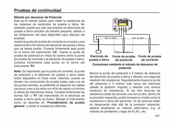
107
Pruebas de continuidad
Metodo por descenso de PotencialEste es el método básico para medir la resistencia delos sistemas de electrodos de puesta a tierra. Noobstante, puede que sólo sea práctico en electrodos depuesta a tierra sencillos de tamaño pequeño, debido alas limitaciones del área disponible para efectuar laspruebas.Inserte la punta de prueba de corriente en el suelo a unadistancia 30 a 50 metros del electrodo de puesta a tierraque se desea probar. Conecte firmemente esta puntaen el borne del instrumento ’C2’. Inserte la punta deprueba de potencial en mitad de camino entre la puntade prueba de corriente y el electrodo de puesta a tierra.Conecte firmemente esta punta en el borne delinstrumento ’P2’.
Nota: Es importante que la punta de corriente, la puntade potencial y el electrodo de puesta a tierra esténtodos dispuestos en línea recta. Además, cuando setienden los conductores de prueba hasta cada una delas puntas remotas, es preferible no disponer los cablescercanos unos a los otros con el fin de reducir al mínimoel efecto de inductancia mutua. Conecte firmemente losbornes ’C1’ y ’P1’ del instrumento en el electrodo depuesta a tierra como se ilustra. Maneje el instrumentocomo se describe en ’Procedimiento de pruebageneral’, y anote la resistencia obtenida.
Conexiones mediante el método de descenso depotencial
Mueva la punta del potencial a 3 metros de distanciadel electrodo de puesta a tierra y efectúe una segundamedición de resistencia. Seguidamente mueva la puntadel potencial a 3 metros más cerca del electrodo(desde la posición original) y efectúe una terceramedición de resistencia. Si las tres lecturas deresistencia están de acuerdo una con la otra, dentro dela precisión requerida, podrá tomarse su media como laresistencia a tierra del electrodo. Si las lecturas estánen desacuerdo más allá de la precisión requerida,deberá emplearse un método alternativo, e.g. elmétodo de pendiente o regla de 61,8%, etc.
3m 3m
15m to 25m 15m to 25m
�C �Electrodo de puesta a tierra
Punta de pruebade potencial
Punta de pruebade corriente
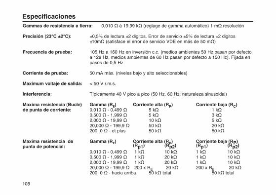
108
Gammas de resistencia a tierra: 0,010 Ω à 19,99 kΩ (reglage de gamma automático) 1 mΩ resolución
Precisión (23°C ±2°C): ±0,5% de lectura ±2 digitos. Error de servicio ±5% de lectura ±2 digitos ±10mΩ (satisface el error de servicio VDE en más de 50 mΩ)
Frecuencia de prueba: 105 Hz a 160 Hz en inversión c.c. (medios ambientes 50 Hz pasan por defecto a 128 Hz, medios ambientes de 60 Hz pasan por defecto a 150 Hz). Fijada en pasos de 0,5 Hz
Corriente de prueba: 50 mA máx. (niveles bajo y alto seleccionables)
Maximum voltaje de salida: < 50 V r.m.s.
Interferencia: Típicamente 40 V pico a pico (50 Hz, 60 Hz, naturaleza sinusoidal)
Maxima resistencia (Bucle) Gamma (RE) Corriente alta (RP) Corriente baja (RC)de punta de corriente: 0,010 Ω - 0,499 Ω 5 kΩ 1 kΩ
0,500 Ω - 1,999 Ω 5 kΩ 3 kΩ2,000 Ω - 19,99 Ω 10 kΩ 5 kΩ20,000 Ω - 199,9 Ω 50 kΩ 20 kΩ200, 0 Ω - et plus 50 kΩ 50 kΩ
Maxima resistencia de Gamma (RE) Corriente alta (RP) Corriente baja (RP)punta de potencial: (Rp1) (Rp2) (Rp1) (Rp2)
0,010 Ω - 0,499 Ω 1 kΩ 10 kΩ 1 kΩ 10 kΩ0,500 Ω - 1,999 Ω 1 kΩ 20 kΩ 1 kΩ 10 kΩ2,000 Ω - 19,99 Ω 1 kΩ 20 kΩ 1 kΩ 10 kΩ20,000 Ω - 199,9 Ω 200 x RE 20 kΩ 200 x RE 20 kΩ200, 0 Ω - hacia arriba 50 kΩ total 50 kΩ total
Especificaciones
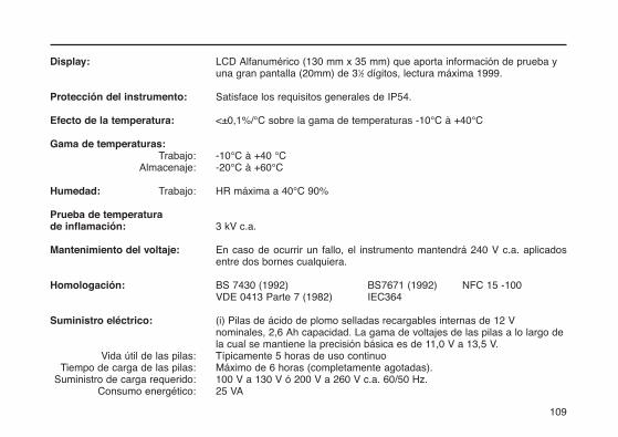
109
Display: LCD Alfanumérico (130 mm x 35 mm) que aporta información de prueba y una gran pantalla (20mm) de 31⁄2 dígitos, lectura máxima 1999.
Protección del instrumento: Satisface los requisitos generales de IP54.
Efecto de la temperatura: <±0,1%/°C sobre la gama de temperaturas -10°C à +40°C
Gama de temperaturas:Trabajo: -10°C à +40 °C
Almacenaje: -20°C à +60°C
Humedad: Trabajo: HR máxima a 40°C 90%
Prueba de temperatura de inflamación: 3 kV c.a.
Mantenimiento del voltaje: En caso de ocurrir un fallo, el instrumento mantendrá 240 V c.a. aplicados entre dos bornes cualquiera.
Homologación: BS 7430 (1992) BS7671 (1992) NFC 15 -100VDE 0413 Parte 7 (1982) IEC364
Suministro eléctrico: (i) Pilas de ácido de plomo selladas recargables internas de 12 V nominales, 2,6 Ah capacidad. La gama de voltajes de las pilas a lo largo de la cual se mantiene la precisión básica es de 11,0 V a 13,5 V.
Vida útil de las pilas: Típicamente 5 horas de uso continuoTiempo de carga de las pilas: Máximo de 6 horas (completamente agotadas).
Suministro de carga requerido: 100 V a 130 V ó 200 V a 260 V c.a. 60/50 Hz.Consumo energético: 25 VA
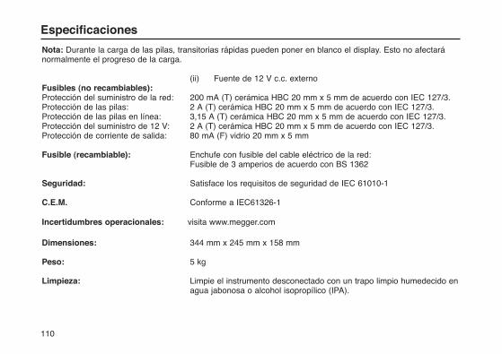
110
Nota: Durante la carga de las pilas, transitorias rápidas pueden poner en blanco el display. Esto no afectaránormalmente el progreso de la carga.
(ii) Fuente de 12 V c.c. externoFusibles (no recambiables):Protección del suministro de la red: 200 mA (T) cerámica HBC 20 mm x 5 mm de acuerdo con IEC 127/3.Protección de las pilas: 2 A (T) cerámica HBC 20 mm x 5 mm de acuerdo con IEC 127/3.Protección de las pilas en línea: 3,15 A (T) cerámica HBC 20 mm x 5 mm de acuerdo con IEC 127/3.Protección del suministro de 12 V: 2 A (T) cerámica HBC 20 mm x 5 mm de acuerdo con IEC 127/3.Protección de corriente de salida: 80 mA (F) vidrio 20 mm x 5 mm
Fusible (recambiable): Enchufe con fusible del cable eléctrico de la red:Fusible de 3 amperios de acuerdo con BS 1362
Seguridad: Satisface los requisitos de seguridad de IEC 61010-1
C.E.M. Conforme a IEC61326-1
Incertidumbres operacionales: visita www.megger.com
Dimensiones: 344 mm x 245 mm x 158 mm
Peso: 5 kg
Limpieza: Limpie el instrumento desconectado con un trapo limpio humedecido en agua jabonosa o alcohol isopropílico (IPA).
Especificaciones

111
La especificación CDE 0413 parte 7 determina queestas instrucciones deberán contener una tabla o undiagrama mostrando el valor máximo que elinstrumento debe indicar en ciertas condiciones. Unaprueba a tierra en cualquier sistema de electrodosnormalmente sería realizada de acuerdo con unaespecificación particular. Así pues, incluso a la peorprecisión del instrumento, la lectura nunca estará sobreel valor limitado requerido por la especificaciónparticular dada.
La tabla incluida a vuelta de hoja ilustra la lecturamáxima que será indicada por el instrumento (a suerror máximo) para asegurar que sea satisfecho elvalor máximo de la resistencia a tierra dada en laespecificación de prueba del electrodo de puesta atierra.
Nota: La posición de la coma decimal en la columna devalores de resistencia máximos es correcta paralecturas de resistencia de <2Ω. Para la columna de 2Ωa 20Ω, y la columna de >20Ω, la coma decimal deberámoverse según convenga. Para lecturas máximassuperiores a 200Ω, use la columna de la derecha yajuste la coma decimal según convenga.
La tabla incluye la lectura máxima que sería permitidapara un valor de resistencia máximo conocido,suponiendo que el instrumento sea usado según se ha
especificado.
Si se conoce una resistencia máxima, este valor sehallará en la columna de la izquierda. La lecturamáxima que puede indicar el instrumento se hallaráleyendo a lo largo de las tres columnas de la derecha,dependiendo de la gama del valor que se desea medir.
Por ejemplo, si 10Ω es el valor de la resistenciamáxima, como éste es inferior a 20Ω se usa la columnacentral de las tres columnas de la derecha. Estacolumna muestra que una lectura inferior a 9,49Ωasegurará que, teniendo en cuenta las tolerancias delinstrumento, la resistencia medida sea inferior a 10Ω.
Podrá adjudicarse un valor máximo a una mediciónusando la tabla a la inversa. Por ejemplo, una lecturade 1,545Ω aportaría un límite máximo al valor de laresistencia entre 1,600Ω y 1,650Ω. Puede emplearseinterpolación para incrementar la precisión si serequiere.
Nota: Esta tabla sólo podrá usarse para lecturas de unDET2/2.
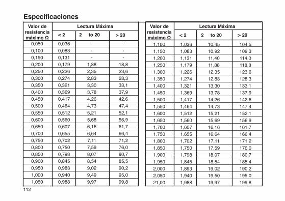
112
Valor deresistenciamáximo Ω
< 2 > 20 2 to 20
Lectura Máxima Valor deresistenciamáximo Ω < 2 > 20 2 to 20
Lectura Máxima
0,050 -0,036 -
0,100 -0,083 -
0,150 -0,131 -
0,200 18,80,179 1,88
0,250 23,60,226 2,35
0,300 28,30,274 2,83
0,350 33,10,321 3,30
0,400 37,90,369 3,78
0,450 42,60,417 4,26
0,500 47,40,464 4,73
0,550 52,10,512 5,21
0,600 56,90,560 5,68
0,650 61,70,607 6,16
0,700 66,40,655 6,64
0,750 71,20,702 7,11
0,800 76,00,750 7,59
0,850 80,70,798 8,07
0,900 85,50,845 8,54
0,950 90,20,983 9,02
1,000 95,00,940 9,49
1,050 99,80,988 9,97
1,100 104,51,036 10,45
1,150 109,31,083 10,92
1,200 114,01,131 11,40
1,250 118,81,179 11,88
1,300 123,61,226 12,35
1,350 128,31,274 12,83
1,400 133,11,321 13,30
1,450 137,91,369 13,78
1,500 142,61,417 14,26
1,550 147,41,464 14,73
1,600 152,11,512 15,21
1,650 156,91,560 15,69
1,700 161,71,607 16,16
1,750 166,41,655 16,64
1,800 171,21,702 17,11
1,850 176,01,750 17,59
1,900 180,71,798 18,07
1,950 185,41,845 18,54
2,000 190,21,893 19,02
2,050 195,01,940 19,50
21,00 199,81,988 19,97
Especificaciones
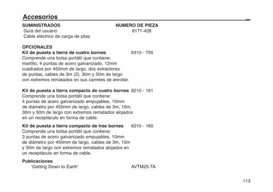
113
SUMINISTRADOS NUMERO DE PIEZAGuía del usuario 6171-428Cable eléctrico de carga de pilas
OPCIONALESKit de puesta a tierra de cuatro bornes 6310 - 755Comprende una bolsa portátil que contiene:martillo, 4 puntas de acero galvanizado, 12mm cuadrados por 450mm de largo, dos extractores de puntas, cables de 3m (2), 30m y 50m de largo con extremos rematados en sus carretes de enrollar.
Kit de puesta a tierra compacto de cuatro bornes 6210 - 161Comprende una bolsa portátil que contiene: 4 puntas de acero galvanizado empujables, 10mm de diámetro por 450mm de largo, cables de 3m, 15m, 30m y 50m de largo con extremos rematados alojados en un receptáculo en forma de cable.
Kit de puesta a tierra compacto de tres bornes 6210 - 160Comprende una bolsa portátil que contiene:3 puntas de acero galvanizado empujables, 10mm de diámetro por 450mm de largo, cables de 3m, 15m y 30m de largo con extremos rematados alojados en un receptáculo en forma de cable.
Publicaciones‘Getting Down to Earth’ AVTM25-TA
Accesorios
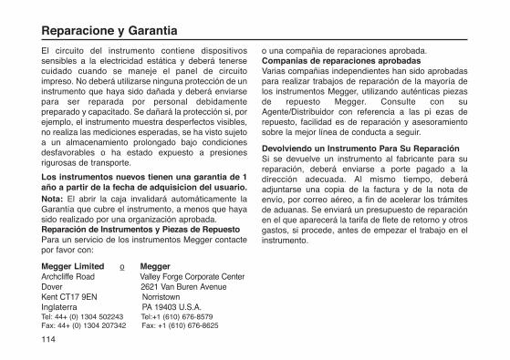
El circuito del instrumento contiene dispositivossensibles a la electricidad estática y deberá tenersecuidado cuando se maneje el panel de circuitoimpreso. No deberá utilizarse ninguna protección de uninstrumento que haya sido dañada y deberá enviarsepara ser reparada por personal debidamentepreparado y capacitado. Se dañará la protección si, porejemplo, el instrumento muestra desperfectos visibles,no realiza las mediciones esperadas, se ha visto sujetoa un almacenamiento prolongado bajo condicionesdesfavorables o ha estado expuesto a presionesrigurosas de transporte.
Los instrumentos nuevos tienen una garantia de 1año a partir de la fecha de adquisicion del usuario.Nota: El abrir la caja invalidará automáticamente laGarantía que cubre el instrumento, a menos que hayasido realizado por una organización aprobada.Reparación de Instrumentos y Piezas de RepuestoPara un servicio de los instrumentos Megger contactepor favor con:
Megger Limited o MeggerArchcliffe Road Valley Forge Corporate CenterDover 2621 Van Buren AvenueKent CT17 9EN Norristown Inglaterra PA 19403 U.S.A.Tel: 44+ (0) 1304 502243 Tel:+1 (610) 676-8579Fax: 44+ (0) 1304 207342 Fax: +1 (610) 676-8625
o una compañia de reparaciones aprobada.Companias de reparaciones aprobadasVarias compañias independientes han sido aprobadaspara realizar trabajos de reparación de la mayoría delos instrumentos Megger, utilizando auténticas piezasde repuesto Megger. Consulte con suAgente/Distribuidor con referencia a las pi ezas derepuesto, facilidad es de reparación y asesoramientosobre la mejor línea de conducta a seguir.
Devolviendo un Instrumento Para Su ReparaciónSi se devuelve un instrumento al fabricante para sureparación, deberá enviarse a porte pagado a ladirección adecuada. Al mismo tiempo, deberáadjuntarse una copia de la factura y de la nota deenvío, por correo aéreo, a fin de acelerar los trámitesde aduanas. Se enviará un presupuesto de reparaciónen el que aparecerá la tarifa de flete de retorno y otrosgastos, si procede, antes de empezar el trabajo en elinstrumento.
114
Reparacione y Garantia


M
Megger Limited
Archcliffe Road Dover
Kent CT17 9EN ENGLAND
T +44 (0)1 304 502101
F +44 (0)1 304 207342
Megger
4271 Bronze Way, Dallas,
TX 75237-1019 USA
T +1 800 723 2861
T +1 214 333 3201
F +1 214 331 7399
Megger
Z.A. Du Buisson de la Couldre
23 rue Eugène Henaff
78190 TRAPPES France
T +33 (0) 1 30.16.08.90
F +33 (0) 1 34.61.23.77
OTHER TECHNICAL SALES OFFICES
Toronto CANADA, Sydney AUSTRALIA, Mumbai INDIA, Madrid SPAIN and the Kingdom of BAHRAIN.
Megger products are distributed in 146 countries worldwide.
This instrument is manufactured in the United Kingdom.
The company reserves the right to change the specification or design without prior notice.
Megger is a registered trademark
Part No. 6171-428 V11 Printed in England 0908www.megger.com
Related Documents