AVM52ERT VELLEMAN 1 AVM52ERT – Analogue Earth Resistance Tester 1. Introduction & Features Thank you for buying the AVM52ERT ! Please read the manual carefully before bringing this device into service. • The modern design limits the influence of the earth voltage and the earth resistance of auxiliary earth bars to a minimum. • Press the BATT.CHECK button to test the auxiliary earth resistance and the connection cable. The OK lamp lights up when the device is ready to perform accurate earth resistance measurements. • Low power consumption : max. 12V/100mA. • Push buttons allow smooth operation of the device. • The earth resistance value can be read directly from the scale. • You only need to press the SIMPLIFIED MEAS. button for simplified measurements. No shorting wire is required since terminals P and C can be shorted internally simply by pressing this button. • Battery replacement is easy. • The carrying case in hard plastic is water-resistant and accommodates all accessories. 2. Specifications Measuring Ranges Earth Resistance 10/100/1000Ω Earth Voltage 30V AC (5KΩ/V approx.) Accuracy Earth Resistance ±5% of full scale Earth Voltage ±5% of full scale Measurement System Measure earth resistance with a CC inverter, 800Hz, ± 2mA Measure earth voltage through a rectifier, type 5KΩ/V, ± 40~500Hz Withstand Voltage 1500V AC for 60 seconds between electrical circuit and the housing. Self-Check Facility Press the BATT.CHECK button to test the earth resistance and the connection with terminals P and C. The OK lamp comes on. Batteries 8 x 1.5V AA-battery Dimensions 140 (L) x 140 (W) x 90 (D) mm Weight ±800g Accessories • test leads (red15m / yellow 10m / green 5m) • auxiliary earth bars • carrying case

Welcome message from author
This document is posted to help you gain knowledge. Please leave a comment to let me know what you think about it! Share it to your friends and learn new things together.
Transcript

AVM52ERT VELLEMAN 1
AVM52ERT – Analogue Earth Resistance Tester 1. Introduction & Features Thank you for buying the AVM52ERT ! Please read the manual carefully before bringing this device into service. • The modern design limits the influence of the earth voltage and the earth resistance of
auxiliary earth bars to a minimum. • Press the BATT.CHECK button to test the auxiliary earth resistance and the connection
cable. The OK lamp lights up when the device is ready to perform accurate earth resistance measurements.
• Low power consumption : max. 12V/100mA. • Push buttons allow smooth operation of the device. • The earth resistance value can be read directly from the scale. • You only need to press the SIMPLIFIED MEAS. button for simplified measurements. No
shorting wire is required since terminals P and C can be shorted internally simply by pressing this button.
• Battery replacement is easy. • The carrying case in hard plastic is water-resistant and accommodates all accessories. 2. Specifications Measuring Ranges Earth Resistance 10/100/1000Ω Earth Voltage 30V AC (5KΩ/V approx.) Accuracy Earth Resistance ±5% of full scale Earth Voltage ±5% of full scale Measurement System Measure earth resistance with a CC inverter, 800Hz, ± 2mA Measure earth voltage through a rectifier, type 5KΩ/V, ± 40~500Hz Withstand Voltage 1500V AC for 60 seconds between electrical circuit and the housing. Self-Check Facility Press the BATT.CHECK button to test the earth resistance and the
connection with terminals P and C. The OK lamp comes on. Batteries 8 x 1.5V AA-battery Dimensions 140 (L) x 140 (W) x 90 (D) mm Weight ±800g Accessories • test leads (red15m / yellow 10m / green 5m) • auxiliary earth bars • carrying case
AVM52ERT VELLEMAN 2
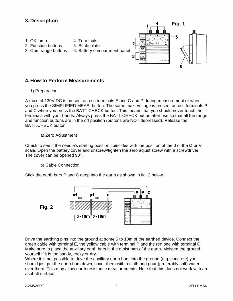
3. Description 1. OK lamp 4. Terminals 2. Function buttons 5. Scale plate 3. Ohm range buttons 6. Battery compartment panel 4. How to Perform Measurements
1) Preparation A max. of 130V DC is present across terminals E and C and P during measurement or when you press the SIMPLIFIED MEAS. button. The same max. voltage is present across terminals P and C when you press the BATT.CHECK button. This means that you should never touch the terminals with your hands. Always press the BATT.CHECK button after use so that all the range and function buttons are in the off position (buttons are NOT depressed). Release the BATT.CHECK button.
a) Zero Adjustment Check to see if the needle’s starting position coincides with the position of the 0 of the Ω or V scale. Open the battery cover and unscrew/tighten the zero adjust screw with a screwdriver. The cover can be opened 90°.
b) Cable Connection Stick the earth bars P and C deep into the earth as shown in fig. 2 below. Drive the earthing pins into the ground at some 5 to 10m of the earthed device. Connect the green cable with terminal E, the yellow cable with terminal P and the red one with terminal C. Make sure to place the auxiliary earth bars in the moist part of the earth. Moisten the ground yourself if it is too sandy, rocky or dry. Where it is not possible to drive the auxiliary earth bars into the ground (e.g. concrete) you should just put the earth bars down, cover them with a cloth and pour (preferably salt) water over them. This may allow earth resistance measurements. Note that this does not work with an asphalt surface.
Fig. 1
Fig. 2

AVM52ERT VELLEMAN 3
Keep the connection cables separate when connecting them. The result of the measurement is affected by the induction of current or voltage when the cables are touching or entangled. Measurement errors may result if the resistance of the auxiliary earth bars exceeds 2KΩ. Be careful, therefore, when you put the auxiliary earth bars P1 and C1 in the damp earth. Also check the connection of the cables with the terminals.
2) Measuring the Earth Voltage of the Earthed Equipment under Test Press the AC V button. The earth voltage is indicated on the V scale. The earth resistance measurement may be inaccurate if the earth voltage > 5V. Turn off the power source of the tested device or reduce the earth voltage to avoid this problem. Note : The measurement is not influenced if the x1Ω, x10Ω or x100Ω button is in the pressed-
down position.
3) Checking Battery Voltage & Cable Connection Both battery strength and the cable connections can be tested when the BATT.CHECK button is placed in the pressed-down position :
a) Battery Voltage The battery voltage is sufficient when the needle stays in the GOOD zone of the scale. If not, replace the batteries (see “5. Battery Replacement” on p. 5).
b) Cable Connection The OK lamp lights up if the cables of terminals P and C are connected properly and if the earth resistance of the auxiliary earth bars falls within the limits you have determined. If the lamp does not come on : check the connection of the cables with terminals P and C or reduce the earth resistance of the auxiliary earth bars to an acceptable level by moistened the ground with water or moving the earth bars. Short the alligator clips at the end of the yellow and red wires to check them for damage. Note that you can check the battery voltage without connecting any cables. Simply press the BATT.CHECK button once. The OK lamp does not come on.
4) Measuring Earth Resistance Press one of the range buttons x 1Ω, x 10Ω or 100Ω. Press the MEAS. button next. Multiply the reading by 10 for the x 10Ω-range or by 100 for the100Ω-range. The OK lamp is ON when the instrument is working normally. If the lamp is not lit, this indicates that normal operation is made impossible by an excessive earth resistance across terminals C and E. Verify again that there is no contact between the cables and recheck the earth resistance of the auxiliary earth bars according to the principles outlined in “3) Checking Battery Voltage & Cable Connection” above. Despite all previous checks, it is still possible for the OK lamp to stay off and for the needle to exceed the upper limit value. This can be due to several things : the tested device may not be functioning properly, its cables may be damaged or the green connection cable may be damaged.

AVM52ERT VELLEMAN 4
5) Simplified Earth Resistance Measurement This method is recommended when measuring an earth resistance > 10Ω or when it is impossible to drive auxiliary earth bars into the ground. An approximate value can be obtained through the two-wire system, which uses previously earthed devices (see fig. 3 below). Note : Make sure that the earth is connected to terminal P when measuring earth resistance
through mains power (A). Press the AC V button as outlined in “2) Earth Voltage Measurement of Earthed Equipment under Test” to measure the earth voltage of the equipment under test and make certain that earth voltage is below 2V. Press the “x10Ω” button and then the MEAS. button. Read the earth resistance from the scale. Press the “x100Ω” button if the needle tilts to the far right. The obtained reading (RE) is a renders the approximate earth resistance value. There is no need for external shorting as terminals P and C are shorted internally. The earth leakage breaker will not trip because the measuring current is as low as 2mA. The OK lamp is lit in the normal operation mode whether the simplified or the ordinary measurement method is used (this indicates that continuity exists between the various terminals E, P and C). In case of the simplified measurement method only two terminals are used. The earth resistance “re” of an earthed electrode connected to terminal P should be added to a true earth resistance value REX. Therefore, the earth resistance reading is the result of the following formula : RE = REX + re Suppose that “re” is a known value : Let us also assume that RE is 100Ω and that the earth resistance to be measured is e.g. 100Ω. Consequently, the true earth resistance is expressed as : REX = (100Ω) – re Since re is greater than 0, a true earth resistance may be expressed as follows : REX ≤ 100Ω
Fig. 3

AVM52ERT VELLEMAN 5
When measuring an earth resistance of several dozen ohms, we may assume that the indicated earth resistance is a true value. 5. Battery Replacement 1. Open the battery cover 90°. 2. Raise the tab protruding from the compartment. 3. Pull out the battery holder. 4. Remove the batteries and insert 8 new AA-batteries. Respect the polarity indications. 5. Push the holder back into the housing and close the battery compartment. SAFETY WARNING This instrument must be used by a competent, trained person and operated in strict accordance with the instructions. Velleman does not accept liability for damage or injuries caused by misuse or non-compliance with the instructions or safety procedures. It is essential that you read, understand and respect the safety rules contained in this manual. The contents and the specifications can be subject to change without prior notice.
AVM52ERT – Analoge aardingsmeter 1. Inleiding & Kenmerken Dank u voor uw aankoop ! Lees de handleiding aandachtig voor u het toestel in gebruik neemt. • Dankzij het moderne ontwerp blijft de invloed van de aardspanning en van de
spreidingsweerstand van de bijkomende aardingspinnen beperkt. • Druk op de BATT.CHECK knop om de bijkomende spreidingsweerstand en de
verbindingskabel te testen. Het OK lampje licht op wanneer het toestel klaar is om nauwkeurige spreidingsweerstandsmetingen uit te voeren.
• Laag verbruik : max. 12V/100mA. • Drukknoppen voor makkelijke bediening van het toestel. • Spreidingsweerstand kan rechtstreeks van de schaal worden afgelezen. • Druk op de “Simplified Meas.” knop voor vereenvoudigde metingen. U hoeft dus geen
kortsluitdraad te gebruiken want u kunt aansluitklemmen P en C intern kortsluiten met deze knop.
• U kunt de batterijen makkelijk vervangen. • Het draagkoffertje uit hard plastic is waterbestendig en biedt plaats aan alle accessoires. 2. Specificaties Meetbereiken Spreidingsweerstand 10/100/1000Ω Aardspanning 30V AC (± 5KΩ/V)

AVM52ERT VELLEMAN 6
Nauwkeurigheid Spreidingsweerstand ±5% van volle schaal Aardspanning ±5% van volle schaal Meetsysteem Spreidingsweerstand meten via CC inverter, 800Hz, ± 2mA Aardspanning meten via gelijkrichter, type 5KΩ/V, ± 40~500Hz Isolatiespanning 1500V AC gedurende 60 sec. tussen elektrische schakeling en
behuizing. Zelfcontrolefunctie Druk op de BATT.CHECK knop om de spreidingsweerstand en de
verbinding met de C en P aansluitklemmen te testen. Het OK lampje licht op.
Batterijen 8 x 1.5V AA-batterij Afmetingen 140 (L) x 140 (B) x 90 (D) mm Gewicht ±800g Accessoires • testsnoeren (rood15m / geel/ 10m, groen 5m) • bijkomende aardingspinnen • draagtas 3. Beschrijving 1. OK lampje 4. Aansluitklemmen 2. Functieknoppen 5. Schaal 3. Knoppen voor Ω-bereik 6. Deksel van batterijvak 4. Metingen uitvoeren
1) Voorbereiding Tijdens de metingen of wanneer u de SIMPLIFIED MEAS. knop indrukt, bevindt zich max. 130V DC tussen aansluitklemmen E, P en C. Dezelfde max. spanning bevindt zich tussen aansluitklemmen P en C wanneer u de BATT.CHECK knop indrukt. Raak de aansluitklemmen dus nooit aan met uw handen. Druk na gebruik altijd BATT.CHECK in om alle bereik- en functieknoppen in de aanvangsstand te plaatsen (= niet ingedrukt). Laat vervolgens de BATT.CHECK knop los.
a) Nulregeling Ga na of de beginstand van de naald overeenkomt met de positie van de 0 op de Ω of V schaal. Open het batterijvak en stel de nulregelschroef bij met een schroevendraaier indien de naald niet op de 0 staat. U kunt het deksel van het batterijvak onder een hoek van max. 90° plaatsen met de rest van de behuizing.
Fig. 1
AVM52ERT VELLEMAN 7
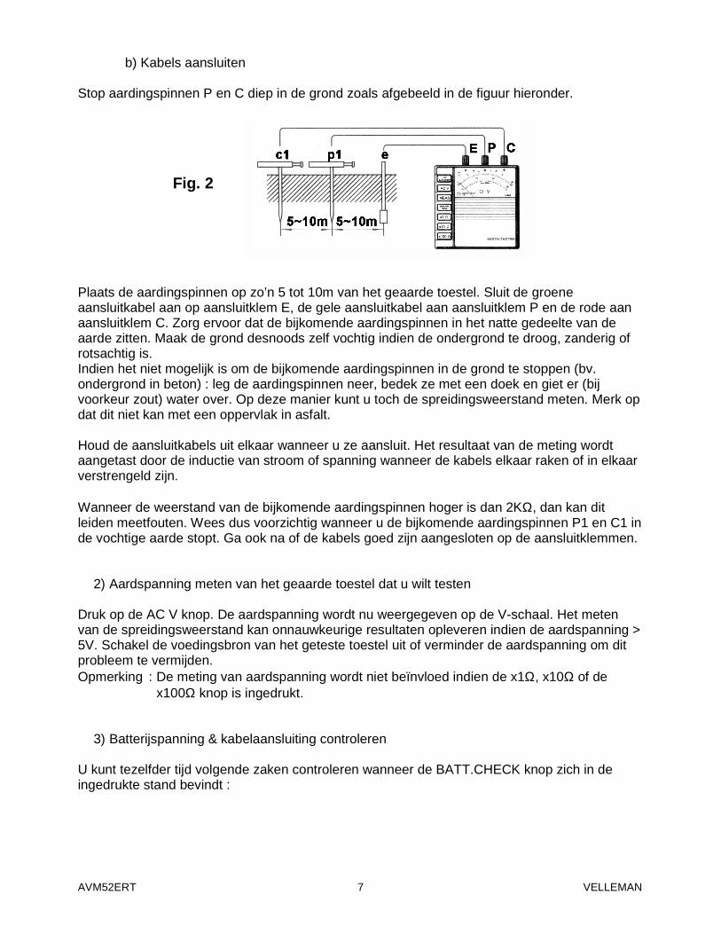
b) Kabels aansluiten Stop aardingspinnen P en C diep in de grond zoals afgebeeld in de figuur hieronder. Plaats de aardingspinnen op zo’n 5 tot 10m van het geaarde toestel. Sluit de groene aansluitkabel aan op aansluitklem E, de gele aansluitkabel aan aansluitklem P en de rode aan aansluitklem C. Zorg ervoor dat de bijkomende aardingspinnen in het natte gedeelte van de aarde zitten. Maak de grond desnoods zelf vochtig indien de ondergrond te droog, zanderig of rotsachtig is. Indien het niet mogelijk is om de bijkomende aardingspinnen in de grond te stoppen (bv. ondergrond in beton) : leg de aardingspinnen neer, bedek ze met een doek en giet er (bij voorkeur zout) water over. Op deze manier kunt u toch de spreidingsweerstand meten. Merk op dat dit niet kan met een oppervlak in asfalt. Houd de aansluitkabels uit elkaar wanneer u ze aansluit. Het resultaat van de meting wordt aangetast door de inductie van stroom of spanning wanneer de kabels elkaar raken of in elkaar verstrengeld zijn. Wanneer de weerstand van de bijkomende aardingspinnen hoger is dan 2KΩ, dan kan dit leiden meetfouten. Wees dus voorzichtig wanneer u de bijkomende aardingspinnen P1 en C1 in de vochtige aarde stopt. Ga ook na of de kabels goed zijn aangesloten op de aansluitklemmen.
2) Aardspanning meten van het geaarde toestel dat u wilt testen Druk op de AC V knop. De aardspanning wordt nu weergegeven op de V-schaal. Het meten van de spreidingsweerstand kan onnauwkeurige resultaten opleveren indien de aardspanning > 5V. Schakel de voedingsbron van het geteste toestel uit of verminder de aardspanning om dit probleem te vermijden. Opmerking : De meting van aardspanning wordt niet beïnvloed indien de x1Ω, x10Ω of de
x100Ω knop is ingedrukt.
3) Batterijspanning & kabelaansluiting controleren U kunt tezelfder tijd volgende zaken controleren wanneer de BATT.CHECK knop zich in de ingedrukte stand bevindt :
Fig. 2

AVM52ERT VELLEMAN 8
a) Batterijspanning De batterijspanning is voldoende wanneer de naald zich in de “GOOD” zone bevindt. Zoniet, dan moet u de batterijen vervangen (zie “5. Batterijen vervangen” op blz. 10).
b) Kabels aansluiten Het OK lampje brandt indien de kabels van aansluitklemmen P en C goed zijn aangesloten en indien de spreidingsweerstand van de bijkomende aardingspinnen binnen de grenzen valt die u heeft vastgelegd. Indien het lampje niet brandt : controleer de verbinding van de kabels met aansluitklemmen P en C of verlaag de spreidingsweerstand van de bijkomende aardingspinnen tot een gepast niveau. Dit doet u door de grond te bevochtigen met water of door de aardingspinnen te verplaatsen. Creëer een kortsluiting van de alligatorklemmen aan het uiteinde van de rode en de gele kabel om na te gaan of ze niet beschadigd zijn. Merk op dat u geen kabels hoeft aan te sluiten om de batterijspanning te controleren. Druk gewoon 1 x op de BATT.CHECK knop. Het OK lampje gaat niet branden.
4) Meten van spreidingsweerstand Druk op één van de bereikknoppen x 1Ω, x 10Ω of 100Ω. Druk vervolgens op de MEAS. knop. Vermenigvuldig de meting met 10 voor het x 10Ω bereik of met 100 voor het 100Ω bereik. Het OK lampje brandt wanneer het toestel normaal werkt. Indien het lampje niet brandt, dan wijst dit op een te hoge spreidingsweerstand over aansluitklemmen C en E die normale werking onmogelijk maakt. Ga nog eens na of de kabels elkaar niet raken en controleer nog eens de spreidingsweerstand van de bijkomende aardingspinnen volgens de richtlijnen in “3) Batterijspanning & kabelaansluiting controleren” op de vorige pagina. Het kan gebeuren dat het OK lampje niet brandt en dat de naald de maximumwaarde van de schaal overschrijdt ondanks alle voorgaande controles. Verschillende oorzaken zijn mogelijk : foute werking van het geteste toestel, beschadigde aansluitkabels van dat toestel of beschadiging van de groene aansluitkabel.
5) Vereenvoudigde methode om spreidingsweerstand te meten Deze methode valt aan te bevelen wanneer u een spreidingsweerstand meet van meer dan 10Ω of wanneer u geen bijkomende aardingspinnen in de grond kan slaan. U kunt de spreidingsweerstand bij benadering meten via het systeem met twee kabels, dat gebruik maakt van reeds geaarde toestellen (zie figuur 3 op blz. 9). Opmerking : Zorg ervoor dat de aarding is aangesloten op aansluitklem P wanneer u
spreidingsweerstand meet met via de netspanning (A). Druk op de AC V knop (zie ook “2) Aardspanning meten van het geaarde toestel dat u wilt testen”) om de aardspanning te meten van het geteste toestel en vergewis u ervan dat de aardspanning kleiner is dan 2V. Druk op de “x10Ω” knop en dan op de MEAS. knop. Lees de spreidingsweerstand af. Druk de “x100Ω” knop in indien de naald volledig naar rechts overhelt.

AVM52ERT VELLEMAN 9
Het uitgelezen resultaat (RE) is een waarde die bij benadering de spreidingsweerstand weergeeft. U hoeft geen externe kortsluiting op te wekken want aansluitklemmen P en C worden intern kortgesloten. De aardlekschakelaar zal niet overslaan omdat de meetstroom slechts 2mA bedraagt. In de normale bedieningstoestand brandt het OK lampje zowel voor de normale als voor de vereenvoudigde meetmethode (dit duidt op continuïteit tussen de verschillende aansluitklemmen E, C en P). Bij de vereenvoudigde meetmethode worden slechts twee aansluitklemmen gebruikt. Spreidingsweerstand “re” van een geaarde elektrode die is aangesloten op aansluitklem P moet worden opgeteld bij een werkelijke spreidingsweerstand REX. De spreidingsweerstand wordt dus uitgedrukt door volgende formule : RE = REX + re Veronderstellen we dat “re” een gekende waarde is : Veronderstellen we verder dat RE = 100Ω en dat de te meten spreidingsweerstand bv. 100Ω, dan kunnen we de werkelijke spreidingsweerstand uitdrukken als volgt : REX = (100Ω) – re Gezien re groter is dan 0, dan kunnen we de werkelijke spreidingsweerstand als volgt uitdrukken : REX ≤ 100Ω Indien we een spreidingsweerstand meten van een paar tientallen ohms, dan mogen we ervan uitgaan dat de uitgelezen spreidingsweerstand een werkelijke waarde is. 5. Batterijen vervangen 1. Klap het batterijdeksel 90° open. 2. Hef het lipje op dat zich centraal aan de bovenkant van het batterijvak bevindt.
Fig. 3

AVM52ERT VELLEMAN 10
3. Trek de batterijhouder uit het batterijvak. 4. Verwijder de batterijen en breng 8 nieuwe AA-batterijen in. Respecteer de
polariteitsindicaties. 5. Duw de houder terug in de behuizing en sluit het batterijdeksel. VEILIGHEIDSRICHTLIJNEN Dit toestel moet worden bediend door een geschoold persoon en in overeenstemming met de instructies in deze handleiding. Velleman is niet aansprakelijk voor schade of kwetsuren die werden veroorzaakt door ongeoorloofd gebruik of het niet naleven van de veiligheidsrichtlijnen. Het is van groot belang dat u de veiligheidsrichtlijnen leest en ook begrijpt. U moet deze richtlijnen strikt volgen wanneer u het toestel gebruikt. De inhoud en de specificaties van de handleiding kunnen worden gewijzigd zonder voorafgaande kennisgeving.
AVM52ERT – Testeur de terre analogique 1. Introduction & Caractéristiques Nous vous remercions de votre achat ! Lisez la notice attentivement avant la mise en service de l’appareil. • Grâce au design moderne, l’influence de la tension de terre et de la résistance de terre des
piquets de terre auxiliaires est limitée. • Pressez le bouton BATT.CHECK (contrôle des piles) pour tester la résistance de terre
additionnelle et le câble de connexion. La lampe OK s’allume quand l’appareil est prêt à exécuter des mesures de résistances de terre précises.
• Basse consommation : max. 12V/100mA. • Boutons-poussoirs facilitent l’opération de l’appareil. • La résistance de terre est indiquée sur l‘échelle. • Pressez le bouton “Simplified Meas.” pour des mesures simplifiées. Vous n’avez donc pas
besoin d’un câble de court-circuit : ce bouton vous donne la possibilité de court-circuiter les bornes de connexion P et C de façon interne.
• Les piles sont faciles à remplacer. • Le coffret en plastique dur résiste à l’eau et peut accueillir toutes les accessoires. 2. Spécifications Plages de mesure Résistance de terre 10/100/1000Ω Tension de terre 30V CA (±5KΩ/V)
AVM52ERT VELLEMAN 11
Précision Résistance de terre ±5% de pleine échelle Tension de terre ±5% de pleine échelle Système de mesure Mesure de la résistance de terre avec un inverseur CC, 800Hz, ± 2mA Mesure de la tension de terre avec un pont de redressement, type 5KΩ/V, ± 40~500Hz Tension d’isolation 1500V CA pendant 60 sec. entre le circuit électrique et le boîtier. Fonction autocontrôle Pressez le bouton BATT.CHECK pour tester la résistance de terre et
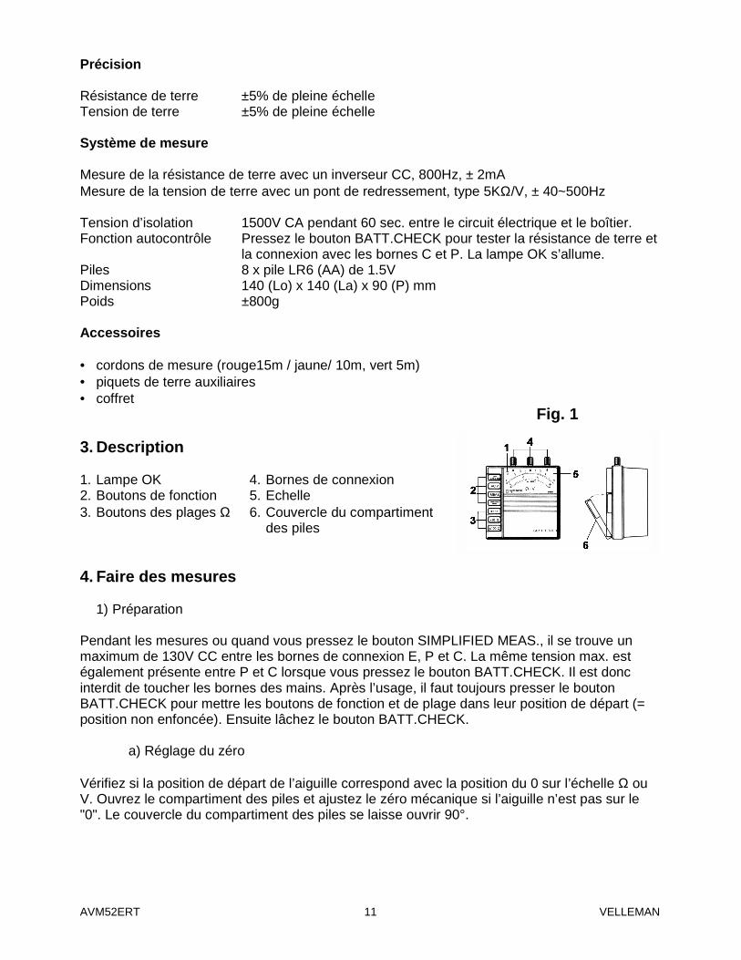
la connexion avec les bornes C et P. La lampe OK s’allume. Piles 8 x pile LR6 (AA) de 1.5V Dimensions 140 (Lo) x 140 (La) x 90 (P) mm Poids ±800g Accessoires • cordons de mesure (rouge15m / jaune/ 10m, vert 5m) • piquets de terre auxiliaires • coffret 3. Description 1. Lampe OK 4. Bornes de connexion 2. Boutons de fonction 5. Echelle 3. Boutons des plages Ω 6. Couvercle du compartiment
des piles 4. Faire des mesures
1) Préparation Pendant les mesures ou quand vous pressez le bouton SIMPLIFIED MEAS., il se trouve un maximum de 130V CC entre les bornes de connexion E, P et C. La même tension max. est également présente entre P et C lorsque vous pressez le bouton BATT.CHECK. Il est donc interdit de toucher les bornes des mains. Après l’usage, il faut toujours presser le bouton BATT.CHECK pour mettre les boutons de fonction et de plage dans leur position de départ (= position non enfoncée). Ensuite lâchez le bouton BATT.CHECK.
a) Réglage du zéro Vérifiez si la position de départ de l’aiguille correspond avec la position du 0 sur l’échelle Ω ou V. Ouvrez le compartiment des piles et ajustez le zéro mécanique si l’aiguille n’est pas sur le "0". Le couvercle du compartiment des piles se laisse ouvrir 90°.
Fig. 1
AVM52ERT VELLEMAN 12
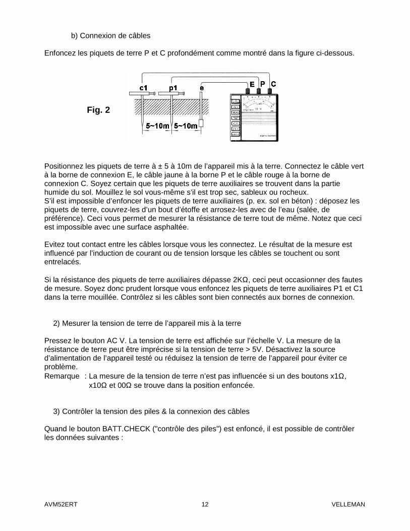
b) Connexion de câbles Enfoncez les piquets de terre P et C profondément comme montré dans la figure ci-dessous. Positionnez les piquets de terre à ± 5 à 10m de l’appareil mis à la terre. Connectez le câble vert à la borne de connexion E, le câble jaune à la borne P et le câble rouge à la borne de connexion C. Soyez certain que les piquets de terre auxiliaires se trouvent dans la partie humide du sol. Mouillez le sol vous-même s’il est trop sec, sableux ou rocheux. S’il est impossible d’enfoncer les piquets de terre auxiliaires (p. ex. sol en béton) : déposez les piquets de terre, couvrez-les d’un bout d’étoffe et arrosez-les avec de l’eau (salée, de préférence). Ceci vous permet de mesurer la résistance de terre tout de même. Notez que ceci est impossible avec une surface asphaltée. Evitez tout contact entre les câbles lorsque vous les connectez. Le résultat de la mesure est influencé par l’induction de courant ou de tension lorsque les câbles se touchent ou sont entrelacés. Si la résistance des piquets de terre auxiliaires dépasse 2KΩ, ceci peut occasionner des fautes de mesure. Soyez donc prudent lorsque vous enfoncez les piquets de terre auxiliaires P1 et C1 dans la terre mouillée. Contrôlez si les câbles sont bien connectés aux bornes de connexion.
2) Mesurer la tension de terre de l’appareil mis à la terre Pressez le bouton AC V. La tension de terre est affichée sur l’échelle V. La mesure de la résistance de terre peut être imprécise si la tension de terre > 5V. Désactivez la source d’alimentation de l’appareil testé ou réduisez la tension de terre de l’appareil pour éviter ce problème. Remarque : La mesure de la tension de terre n’est pas influencée si un des boutons x1Ω,
x10Ω et 00Ω se trouve dans la position enfoncée.
3) Contrôler la tension des piles & la connexion des câbles Quand le bouton BATT.CHECK ("contrôle des piles") est enfoncé, il est possible de contrôler les données suivantes :
Fig. 2

AVM52ERT VELLEMAN 13
a) Tension des piles L’état de charge des piles est satisfaisante lorsque l’aiguille se trouve dans la zone "GOOD". Sinon il faut remplacer les piles (voir “5. Remplacement des piles” à la p.10).
b) Connexion des câbles La lampe OK s’allume si les câbles des bornes de connexion P et C sont bien connectés et si la résistance de terre des piquets de terre auxiliaires tombe dans les limites que vous avez fixées. Si la lampe ne s’allume pas : contrôlez la connexion des câbles avec les bornes de connexion P et C ou réduisez la résistance de terre des piquets de terre auxiliaires jusqu’à un niveau acceptable en mouillant le sol ou en déplaçant les piquets de terre. Court-circuitez les pinces crocodiles à l’extrémité du câble jaune et rouge pour vérifier s’ils n’ont pas été endommagés. Notez que vous n’avez besoin de câbles afin de contrôler l’état de charge des piles. Vous n’avez qu’à presser le bouton BATT.CHECK une fois. La lampe ne sera pas allumée.
4) Mesurer la résistance de terre Pressez un des boutons de plage : x 1Ω, x 10Ω ou 100Ω. Pressez ensuite le bouton MEAS. Multipliez le résultat par 10 pour la plage 10Ω et par 100 pour la plage 100Ω. La lampe OK s’allumera si l’appareil fonctionne de façon normale. Si la lampe ne s’allume pas, ceci indique que la résistance de terre entre les bornes de connexion C et E est trop élevée et rend un fonctionnement normal impossible. Vérifiez de nouveau si les câbles se touchent et contrôlez de nouveau la résistance de terre des piquets de terre auxiliaires selon les directives de “3) Contrôler la tension des piles & la connexion des câbles” à la page précédente. Malgré tous les contrôles précédents, il se peut que la lampe OK ne soit pas allumée et que l’aiguille dépasse la valeur max. de l’échelle. Plusieurs causes sont possibles : un mauvais fonctionnement de l’appareil testé, l’endommagement des câbles de cet appareil ou l’endommagement du câble vert.
5) Méthode simplifiée pour mesurer la résistance de terre Nous recommandons l’emploi de cette méthode lorsque vous mesurez une résistance de terre de plus de 10Ω ou lorsqu’il est impossible d’enfoncer des piquets de terre auxiliaires. Il est possible de déterminer la valeur approximative de la résistance de terre avec le système qui ne demande que deux câbles et emploie des appareils déjà mis à la terre (voir figure 3 à la p. 14). Remarque : Assurez-vous que la terre soit connectée à la borne de connexion P lorsque vous
mesurez la résistance de terre via le réseau électrique (A). Pressez le bouton AC V (voir également “2) Mesurer la tension de terre de l’appareil mis à la terre”) pour mesurer la tension de terre de l’appareil testé et assurez-vous que la tension de terre est inférieure à 2V. Pressez le bouton “x10Ω” et ensuite le bouton MEAS. Lisez la résistance de terre. Pressez le bouton “x100Ω” si l’aiguille bascule à l’extrême droite. Le résultat indiqué (RE) est une valeur représentant la résistance de terre approximative. Il ne faut créer de court-circuit externe comme les bornes de connexion P et C sont court-circuitées de façon interne.

AVM52ERT VELLEMAN 14
Le disjoncteur de perte à la terre ne sera pas déclenché comme le courant de mesure n’est que 2mA. Dans le mode d’opération normal, la lampe OK s’allume aussi bien pour la méthode de mesure normale que pour la méthode simplifiée (ce qui implique qu’il existe une continuité entre les différentes bornes de connexion E, C en P). La méthode simplifiée n’emploie que deux bornes de connexion. La résistance de terre “re” d’une électrode mise à la terre qui est connectée à la borne de connexion P, doit être ajoutée à la résistance de terre réelle REX. La résistance de terre est donc exprimée par la formule suivante : RE = REX + re Supposons que “re” est une valeur connue : Supposons ensuite que RE = 100Ω et que la résistance à mesurer = 100Ω. Nous pouvons alors exprimer la résistance de terre réelle par la formule suivante : REX = (100Ω) – re Comme re > que 0, la résistance de terre réelle se laisse exprimer par la formule suivante : REX ≤ 100Ω Quand nous mesurons une résistance de terre de quelques dizaines d’ohms, nous pouvons supposer que la résistance de terre indiquée est une valeur réelle. 5. Remplacement des piles 1. Ouvrez le couvercle du compartiment des piles 90°. 2. Levez la languette protubérante. 3. Tirez le support des piles du compartiment. 4. Enlevez les piles et insérez 8 nouvelles piles du type LR6 (AA). Respectez les indications de
polarité. 5. Insérez le support dans le boîtier et refermez le compartiment des piles.
Fig. 3
AVM52ERT VELLEMAN 15
PRESCRIPTIONS DE SECURITE Seules les personnes qualifiées peuvent opérer cet appareil. Respectez les instructions de la notice. Velleman ne sera pas responsable de dommages ou de blessures causées par le non respect des instructions de la notice ou par une utilisation défendue. Il est très important de lire, de comprendre et de respecter les instructions de la notice. Le contenu et les spécifications peuvent être modifiées sans avis préalable.
AVM52ERT – MEDIDOR ANALÓGICO DE RESISTENCIA DE TIERRA 1. Introducción & Características ¡Gracias por haber comprado el AVM52ERT! Lea cuidadosamente las instrucciones del manual antes de montarlo. • Gracias al diseño moderno, la influencia de la tensión y la resistencia de tierra de las picas
auxiliares queda limitada. • Apriete el botón BATT.CHECK (prueba de pilas) para comprobar la resistencia de tierra
adicional y el cable de conexión. Se ilumina la lámpara OK si el aparato está listo para hacer mediciones de resistencias de tierra precisas.
• Bajo consumo : máx. 12V/100mA. • Los pulsadores facilitan el uso del aparato. • La resistencia de tierra se visualiza en una escala. • Apriete el botón “Simplified Meas.” para mediciones simplificadas. Por lo tanto, no se
necesita un cable de cortocircuito : este botón le da la posibilidad de cortocircuitar los bornes de conexión P y C de manera interna.
• Es fácil de reemplazar las pilas. • El maletín de plástico duro resiste al agua y contiene todos los accesorios. 2. Especificaciones Rangos de medición Resistencia de tierra 10/100/1000Ω Tensión de tierra 30V AC (±5KΩ/V) Precisión Resistencia de tierra ±5% a escala llena Tensión de tierra ±5% a escala llena Sistema de medición Medición de la resistencia de tierra con un invertidor CC, 800Hz, ± 2mA Medición de la tensión de tierra con un puente rectificador, tipo 5KΩ/V, ± 40~500Hz

AVM52ERT VELLEMAN 16
Tensión de aislamiento 1500V AC durante 60 seg. entre el circuito eléctrico y la caja. Función de autocontrol Apriete el botón BATT.CHECK para comprobar la resistencia de tierra y la conexión con las picas auxiliares C y P. Se ilumina la
lámpara OK. Pilas 8 x pila AA de 1.5V Dimensiones 140 (Lo) x 140 (La) x 90 (P) mm Peso ±800g Accesorios • Puntas de prueba (rojo15m / amarilla/ 10m, verde 5m) • Picas de tierra auxiliares • maletín 3. Descripción 1. Lámpara OK 4. Bornes de conexión 2. Botones de función 5. Escala 3. Botones de rangos Ω 6. Tapa del compartimiento
de pilas 4. Realizar mediciones
1) Preparación Durante las mediciones o apretando el botón SIMPLIFIED MEAS., se indica un máx. de 130V DC entre los bornes de conexión E, P y C. La misma tensión máx. está también presente entre P y C apretando el botón BATT.CHECK. Por lo tanto, no toque nunca los terminales con las manos. Después del uso, siempre apriete el botón BATT.CHECK para colocar los botones de función et de rango en la posición inicial (= posición no apretado). Luego, suelte el botón BATT.CHECK.
a) Ajustar el cero Verifique si la posición inicial de la aguja coincide con la posición del 0 en la escala Ω o V. Abra el compartimiento de pilas y ajuste el tornillo de ajuste cero con un destornillador si la aguja no se encuentra en “0”. Se puede abrir la tapa del compartimiento de pilas 90°.
b) Conectar los cables
Clave las picas auxiliares P y C en la tierra tal como se muestra en la siguiente figura.
Fig. 1
Fig. 2
AVM52ERT VELLEMAN 17
Coloque las picas auxiliares en un espacio de ± 5 a 10m del aparato puesto a tierra. Conecte el cable verde al terminal E, el cable amarillo al terminal P y el cable rojo al terminal C. Asegúrese de clavar las picas auxiliares en una parte húmeda del terreno. Moje el terreno con agua para que se humedezca cuando las picas auxiliares deban clavarse en partes secas, rocosas o arenosas. Si no es posible clavar las picas de tierra auxiliares (p. ej. suelo de hormigón) : coloque las picas de tierra, cúbralas con un paño y mójelas con agua (preferentemente salada). Esto le permite medir la resistencia de tierra. Note que esto no es posible con una superficie de asfalto. Cuando conecte los cables de prueba, asegúrese de que estén separados. Realizando la medición con los cables enrollados o en contacto entre ellos, puede afectar la lectura por la corriente o tensión de inducción. Si la resistencia de las picas de tierra auxiliares es superior a 2KΩ, esto puede causar una medición errónea. Tenga cuidado al clavar las picas de tierra auxiliares P1 y C1 en una parte húmeda del terreno. Asegúrese de que los cables estén bien conectados a los terminales.
2) Medir la tensión de tierra del aparato puesto a tierra Apriete el botón AC V. La tensión de tierra se visualiza en la escala V. Si la tensión de tierra > 5V, esto puede provocar muchos errores en la medición de la resistencia de tierra. Desactive la fuente de alimentación del aparato comprobado o reduzca la tensión de tierra del aparato para evitar este problema. Observación : La medición de la tensión de tierra no se influye si uno de los botones x1Ω, x10Ω
y 00Ω se encuentra en la posición apretada.
3) Controlar la tensión de pilas & la conexión de los cables Apretando el botón BATT.CHECK ("prueba de pilas"), es posible controlar los siguientes datos :
a) Tensión des pilas
El estado de carga de pilas es suficiente si la aguja se encuentra en la zona "GOOD". Si no es el caso, reemplace las pilas (véase “5. Reemplazar las pilas” p.19).
b) Conexión de los cables La lámpara OK se ilumina si los cables de los terminales P y C están bien conectados y si la resistencia de tierra de las picas auxiliares se encuentra dentro de los límites que Ud. ha determinados. Si la lámpara no se ilumina: controle la conexión de los cables con los bornes de conexión P y C o reduzca la resistencia de tierra de las picas de tierra auxiliares hasta un nivel aceptable humedeciendo el suelo o desplazando las picas de tierra. Cortocircuite las pinzas cocodrilos al extremo del cable amarillo y rojo para verificar si no han sido dañados. Note que no necesita cables a fin de controlar el estado de carga de pilas. Sólo apriete el botón BATT.CHECK una vez. La lámpara no se iluminará.
AVM52ERT VELLEMAN 18
4) Medir la resistencia de tierra Apriete uno de los botones de rango : x 1Ω, x 10Ω o 100Ω. Luego, apriete el botón MEAS. Multiplique el resultado por 10 para el rango 10Ω y por 100 para el rango 100Ω. La lámpara OK se iluminará si el aparato funciona de manera normal. Si la lámpara no se ilumina, esto indica que la resistencia de tierra entre los bornes de conexión C y E es demasiado elevada y que un funcionamiento normal es imposible. Vuelva a verificar si los cables realicen un buen contacto y controle la resistencia de tierra de las picas de tierra auxiliares según las directivas de “3) Controlar la tensión de pilas & la conexión de los cables” (véase arriba). A pesar de todos los controles precedentes, es posible que la lámpara OK no se ilumine y que la aguja sobrepase el valor máx. de la escala. Varias causas son posibles : el aparato comprobado funciona mal, los cables del aparato están dañados o está dañado el cable verde.
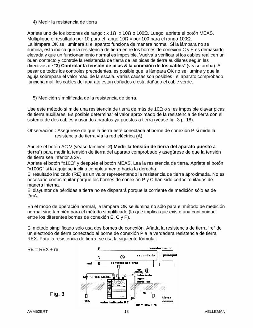
5) Medición simplificada de la resistencia de tierra. Use este método si mide una resistencia de tierra de más de 10Ω o si es imposible clavar picas de tierra auxiliares. Es posible determinar el valor aproximado de la resistencia de tierra con el sistema de dos cables y usando aparatos ya puestos a tierra (véase fig. 3 p. 18). Observación : Asegúrese de que la tierra esté conectada al borne de conexión P si mide la
resistencia de tierra vía la red eléctrica (A). Apriete el botón AC V (véase también “2) Medir la tensión de tierra del aparato puesto a tierra”) para medir la tensión de tierra del aparato comprobado y asegúrese de que la tensión de tierra sea inferior a 2V. Apriete el botón “x10Ω” y después el botón MEAS. Lea la resistencia de tierra. Apriete el botón “x100Ω” si la aguja se inclina completamente hacia la derecha. El resultado indicado (RE) es un valor representando la resistencia de tierra aproximada. No es necesario cortocircuitar porque los bornes de conexión P y C han sido cortocircuitados de manera interna. El disyuntor de pérdidas a tierra no se disparará porque la corriente de medición sólo es de 2mA. En el modo de operación normal, la lámpara OK se ilumina no sólo para el método de medición normal sino también para el método simplificado (lo que implica que existe una continuidad entre los diferentes bornes de conexión E, C y P). El método simplificado sólo usa dos bornes de conexión. Añada la resistencia de tierra “re” de un electrodo de tierra conectado al borne de conexión P a la verdadera resistencia de tierra REX. Para la resistencia de tierra se usa la siguiente fórmula : RE = REX + re
Fig. 3
AVM52ERT VELLEMAN 19
Supongamos que “re” es un valor conocido : Luego, supongamos que RE = 100Ω y que la resistencia a medir = 100Ω. Por lo tanto, es posible exprimir la verdadera resistencia de tierra con la siguiente fórmula : REX = (100Ω) – re Ya que re > 0, use la siguiente fórmula para la verdadera resistencia de tierra : REX ≤ 100Ω Midiendo una resistencia de tierra de varias docenas de ohms, puede suponer que la resistencia de tierra indicada es un verdadero valor. 5. Reemplazar las pilas 1. Abra la tapa del compartimiento de pilas 90°. 2. Quite la lengüeta saliente. 3. Quite el soporte de pilas del compartimiento. 4. Quite las pilas e introduzca 8 nuevas pilas del tipo AA. Respete las indicaciones de
polaridad. 5. Introduzca el soporte en la caja y vuelva a cerrar el compartimiento de pilas. INDICACIONES DE SEGURIDAD Sólo personas calificadas pueden operar este aparato. Respete las instrucciones del manual. Daños causados por descuido de las instrucciones de seguridad de este manual invalidarán su garantía y Velleman no será responsable por ningún daño u otros problemas resultantes. Es muy importante leer, comprender y respetar las instrucciones del manual. Se pueden modificar las especificaciones y el contenido de este manual sin previo aviso.
AVM52ERT – Analoges Prüfgerät für Erdungswiderstand 1. Einführung und Eigenschaften Wir bedanken uns für den Kauf des AVM52ERT! Lesen Sie diese Bedienungsanleitung vor Inbetriebnahme sorgfältig durch. • Dank des modernen Entwurfs bleibt der Einfluss der Erdungsspannung und der
Erdungswiderstand von zusätzlichen Erdspießen beschränkt. • Drücken Sie BATT.CHECK um den zusätzlichen Ausbreitungswiderstand und das
Verbindungskabel zu prüfen. Die OK-Lampe leuchtet wenn das Gerät fertig ist um genaue Ausbreitungswiderstände durchzuführen.
• Niedriger Stromverbrauch : max. 12V/100mA. • Druckknöpfe für einfache Bedienung des Gerätes. • Ausbreitungswiderstand kann direkt von der Skale abgelesen werden.

AVM52ERT VELLEMAN 20
• Drücken Sie “Simplified Meas.” für vereinfachte Messungen. Sie brauchen also kein Kurzschlusskabel denn Sie können die Anschlussklemmen P und C mit diesem Knopf intern kurzschließen.
• Die Batterien können einfach ersetzt werden. • Der Tragekoffer aus hartem Plastik enthält alle Zubehör. 2. Technische Daten Messbereiche Ausbreitungswiderstand 10/100/1000Ω Erdungsspannung 30V AC (± 5KΩ/V) Genauigkeit Ausbreitungswiderstand ±5% von voller Skale Erdungsspannung ±5% von voller Skale Mess-System Ausbreitungswiderstand über DC-Wechselrichter messen, 800Hz, ± 2mA Erdungsspannung über Gleichrichter messen, Type 5KΩ/V, ± 40~500Hz Isolationsspannung 1500V AC während 60 Sek. zwischen elektrischer Schaltung und
Gehäuse. Selbstkontrollefunktion Drücken Sie BATT.CHECK um den Ausbreitungswiderstand und die
Verbindung mit den C- und P-Anschlussklemmen zu überprüfen. Die OK-Lampe leuchtet.
Batterien 8 x 1.5V AA-Batterie Abmessungen 140 (L) x 140 (B) x 90 (D) mm Gewicht ±800g Zubehör • Messleitungen (rot15m / gelb/ 10m, grün 5m) • zusätzliche Erdspieße • Tragekoffer 3. Beschreibung 1. OK-Lampe 4. Anschlussklemmen 2. Funktionsknöpfe 5. Skale 3. Knöpfe für Ω-Bereich 6. Batteriefachdeckel
Abb. 1

AVM52ERT VELLEMAN 21
4. Messungen durchführen
1) Vorbereitung Während der Messungen oder wenn Sie die SIMPLIFIED MEAS.-Taste drücken, gibt es max. 130V DC zwischen den Anschlussklemmen E, P und C. Dieselbe max. Spannung befindet sich zwischen den Anschlussklemmen P und C wenn Sie BATT.CHECK drücken. Berühren Sie die Anschlussklemmen also nie mit den Händen. Drücken Sie nach Gebrauch immer BATT.CHECK um alle Bereichs- und Funktionstasten in der OFF-Position zu stellen (= nicht gedrückt). Lassen Sie die BATT.CHECK-Taste danach los.
a) Nullpunkteinstellung Überprüfen Sie, ob die Anfangsposition der Nadel mit der 0-Position auf der Ω- oder V-Skale übereinstimmt. Öffnen Sie das Batteriefach und regeln Sie die Nullpunkt-Einstellungsschraube mit einem Schraubendreher wenn die Nadel nicht auf 0 steht. Der Batteriefachdeckel kann max. 90° geöffnet werden.
b) Kabel anschließen
Stecken Sie die Erdspieße P und C tief im Boden (siehe Abbildung 2). Stellen Sie die Erdspieße in einem Abstand von etwa 5 bis 10m vom geerdeten Gerät. Schließen Sie das grüne Anschlusskabel an Anschlussklemme E, das gelbe Anschlusskabel an Anschlussklemme P und das rote Anschlusskabel an Anschlussklemme C an. Sorgen Sie dafür, dass die zusätzlichen Erdspieße sich im feuchten Erdboden befinden. Befeuchten Sie den Boden nötigenfalls selber wenn der Untergrund zu trocken, sandig oder felsig ist. Wenn es nicht möglich ist, zusätzlichen Erdspieße in die Erde zu stecken (z.B. Untergrund aus Beton) : legen Sie die Erdspieße nieder, bedecken Sie sie mit einem Tuch und übergießen Sie sie (vorzugsweise Salz). Auf diese Weise können Sie den Ausbreitungswiderstand messen. Bemerken Sie, dass dies mit einer Oberfläche aus Asphalt nicht möglich ist. Halten Sie die Anschlusskabel auseinander wenn Sie sie anschließen. Die Strom- oder Spannungsinduktion beeinflusst das Ergebnis der Messung wenn die Kabel einander berühren oder ineinander geschlungen sind. Wenn der Widerstand der zusätzlichen Erdspieße höher ist als 2KΩ, könnte dies zu Messfehlern führen. Seien Sie also vorsichtig wenn Sie zusätzliche Erdspieße P1 und C1 in der feuchten Erde stecken. Überprüfen Sie auch ob die Kabel richtig an die Anschlussklemmen angeschlossen sind.
Abb. 2
AVM52ERT VELLEMAN 22
2) Erdspannung des geerdeten Gerätes, das Sie prüfen möchten, messen Drücken Sie AC V. Die Erdspannung wird jetzt in der V-Skale angezeigt. Das Messen des Ausbreitungswiderstands kann ungenaue Ergebnisse ergeben wenn die Erdspannung > 5V. Schalten Sie die Stromversorgung des geprüften Gerätes aus oder senken Sie die Erdspannung um das Problem zu vermeiden. Bemerkung : Die Messung der Erdspannung wird nicht beeinflusst wenn die x1Ω, x10Ω oder
x100Ω Taste gedrückt ist.
3) Batteriespannung & Kabelanschluss überprüfen Sie können gleichzeitig folgende Sachen überprüfen wenn die BATT.CHECK-Taste sich in der gedrückte Position befindet :
a) Batteriespannung
Die Batteriespannung genügt wenn die Nadel sich in der “GOOD”-Zone befindet. Wenn das nicht der Fall ist, müssen Sie einen Batteriewechsel durchführen (siehe “5. Batteriewechsel” S. 24).
b) Kabel anschließen Die OK-Lampe brennt wenn die Kabel der Anschlussklemme P und C richtig angeschlossen wurden und wenn der Ausbreitungswiderstand der zusätzlichen Erdspieße innerhalb der Grenze fällt, die Sie festgelegt haben. Wenn die Lampe nicht brennt : Überprüfen Sie die Verbindung der Kabel mit den Anschlussklemmen P und C oder der Ausbreitungswiderstand der zusätzlichen Erdspieße bis das passende Niveau senken. Befeuchten Sie hierfür die Erde mit Wasser oder versetzen Sie die Erdspieße. Kreieren Sie einen Kurzschluss der Krokodilleklemme am Ende des roten und gelben Kabels um zu überprüfen, ob sie nicht beschädigt sind. Bemerken Sie, dass Sie keine 2 Kabel anschließen müssen um die Batteriespannung zu überprüfen. Drücken Sie einfach 1 x die BATT.CHECK-Taste. Die OK-Lampe brennt nicht.
4) Messen des Ausbreitungswiderstand Drücken Sie eine der zwei Bereichstasten x 1Ω, x 10Ω oder 100Ω. Drücken Sie danach die MEAS.-Taste. Multiplizieren Sie die Messung mit 10 für den x 10Ω-Bereich oder mit 100 für den 100Ω-Bereich. Die OK-Lampe brennt wenn das Gerät normal funktioniert. Wenn die Lampe nicht brennt, deutet das auf einen zu hohen Ausbreitungswiderstand über die Anschlussklemme C und E, der ein normales Funktionieren unmöglich macht. Überprüfen Sie nochmals ob die Kabel einander nicht berühren. Überprüfen Sie noch einmal den Ausbreitungswiderstand der zusätzlichen Erdspieße gemäß die Richtlinien in “3) Batteriespannung & Kabelanschluss überprüfen” (siehe vorige Seite). Es könnte passieren, dass die OK-Lampe nicht brennt und dass die Nadel den Maximumwert der Skale trotz aller vorhergehenden Überprüfungen überschreitet. Es sind verschiedene Ursachen möglich : fehlerhaftes Funktionieren des geprüften Gerätes, beschädigte Anschlusskabel des Gerätes oder Beschädigung des grünen Anschlusskabel.

AVM52ERT VELLEMAN 23
5) Vereinfachte Methode um den Ausbreitungswiderstand zu messen Diese Methode empfiehlt sich wenn Sie den Ausbreitungswiderstand über 10Ω messen oder wenn Sie keine zusätzlichen Erdspieße in die Erde stecken. Sie können den Ausbreitungswiderstand annähernd über das System mit zwei Kabeln, das schon geerdete Geräte benutzt, messen (siehe Abbildung 3 unten). Bemerkung : Sorgen Sie dafür, dass die Erdung an die Anschlussklemme P angeschlossen ist
wenn Sie den Ausbreitungswiderstand über die Netzspannung messen (A). Drücken Sie die AC V-Taste (siehe auch “2) Erdungsspannung des geerdeten Gerätes, das Sie prüfen möchten”) um die Erdungsspannung des geprüften Gerätes zu messen und vergewissern Sie sich davon, dass die Erdungsspannung kleiner ist als 2V. Drücken Sie “x10Ω” und danach MEAS. Lesen Sie den Ausbreitungswiderstand ab. Drücken Sie “x100Ω” wenn die Nadel sich völlig nach rechts neigt. Das erzielte Ergebnis (RE) ist ein Wert, der annährend den Ausbreitungswiderstand wiedergibt. Sie brauchen keinen zusätzlichen Kurzschluss auszulösen, denn die Anschlussklemmen P und C werden intern kurzgeschlossen. Der Erdschluss-Schalter wird nicht aktiviert weil der Mess-Strom nur 2mA beträgt. In der normalen Betriebsart brennt die OK-Lampe sowohl für die normale als für die vereinfachte Messmethode (dies weißt darauf hin, dass es Durchgang zwischen den verschiedenen Anschlussklemmen E, C und P gibt). Bei der vereinfachten Messmethode werden nur zwei Anschlussklemmen verwendet. Ausbreitungswiderstand “re” der geerdete Elektrode, die mit Anschlussklemme P verbunden ist, muss beim wirklichen A Ausbreitungswiderstand REX addiert werden. Nachfolgende Formel gibt also den Ausbreitungswiderstand : RE = REX + re Lassen wir annehmen, dass “re” ein bekannter Wert ist : Lassen wir auch annehmen, dass RE = 100Ω und, dass der Ausbreitungswiderstand, der Sie messen möchten, z.B. 100Ω ist. Der wirkliche Ausbreitungswiderstand kann dann wie folgt ausgedrückt werden :
Abb. 3

AVM52ERT VELLEMAN 24
REX = (100Ω) – re Weil re größer ist als 0, kann der wirkliche Ausbreitungswiderstand wie folgt ausgedrückt werden : REX ≤ 100Ω Bei einem Ausbreitungswiderstand von dutzenden Ohms, dürfen Sie davon ausgehen, dass der angezeigte Ausbreitungswiderstand ein wirklicher Wert ist. 5. Batteriewechsel 1. Öffnen Sie den Batteriedeckel 90°. 2. Heben Sie die Lasche, die sich zentral an der Oberseite des Batteriefachs befindet, auf. 3. Ziehen Sie den Batteriehalter aus dem Batteriefach. 4. Entfernen Sie die Batterien und legen Sie 8 neue AA-Batterien ein. Achten Sie auf die
Polarität. 5. Stecken Sie den Halter wieder in das Gehäuse und schließen Sie den Batteriedeckel. SICHERHEITSHINWEISE Installation und Wartung sind einer autorisierten Fachkraft vorbehalten und müssen in Übereinstimmung mit der Anweisungen in dieser Anleitung erfolgen. Bei Schäden, die durch Nichtbeachtung der Bedienungsanleitung verursacht werden, erlischt der Garantieanspruch. Für daraus resultierende Folgeschäden übernimmt Velleman keine Haftung. Es ist von äußerster Wichtigkeit, dass Sie die Sicherheitshinweise lesen und auch begreifen. Folgen Sie die Richtlinien wenn Sie das Gerät verwenden. Änderungen in Technik und Ausstattung vorbehalten.
Related Documents