ITI LIMITED (A Govt. of India Undertaking) Expression of Interest For Design, Supply, Installation, Commissioning, Operations and Maintenance of Intelligent Transportation Systems in a metropolitan city Tender Notice No: ITI/MSPDelhi/2K22/ITS/1 Date: 11.05.2022 Deputy General Manager ITI Limited, MSP-Delhi Core -1, 11 th Floor, Scope Minar, Laxmi Nagar, Delhi-110092 Email: [email protected] Website: www.itiltd.in

Welcome message from author
This document is posted to help you gain knowledge. Please leave a comment to let me know what you think about it! Share it to your friends and learn new things together.
Transcript

ITI LIMITED
(A Govt. of India Undertaking)
Expression of Interest
For
Design, Supply, Installation, Commissioning,
Operations and Maintenance
of Intelligent Transportation Systems in a metropolitan city
Tender Notice No: ITI/MSPDelhi/2K22/ITS/1 Date: 11.05.2022
Deputy General Manager
ITI Limited, MSP-Delhi
Core -1, 11th Floor, Scope Minar,
Laxmi Nagar, Delhi-110092
Email: [email protected]
Website: www.itiltd.in

ITI LIMITED (A Govt. of India Undertaking
Deputy General Manager
ITI Limited, MSP-Delhi
Core-1 Floor-11
Scope Minar Laxmi Nagar,
New Delhi-110092
Email: [email protected]
TENDER NOTICE
Tender Notice to: ITI/MSPDelhi/2K22/ITS/1
Date: 11.05.2022
ITI Limited invites ONLINE bid in TWO COVER SYSTEM (Technical & Financial) from
eligible bidders which must be valid for a minimum period of 120 days from 0the date of
bid opening for following items:
Scope of Work
Design, Supply, Installation, Commissioning,
Operations and Maintenance
of Intelligent Transportation Systems in a
metropolitan city
Interested parties may view and download the tender document containing the detailed
terms & c o n d i t i o n s from the websites T e n d e r W i z a r d P o r t a l , CPP
Portal OR http://itiltd.in
The ONLINE bid is to be submitted in a sealed cover over the Tender Wizard ITI
Limited Portal
The helpdesk nos. for bidding:
a) Shri Prashant Kumar: +91-99100-48364
b) Shri Abhay Sharma: +91-78274-50462
M/s ITI Limited
DGM MSP Delhi

Subject: Expression of Interest (EoI) for Design, Supply, Installation, Commissioning,
Operations and Maintenance of Intelligent Transportation Systems in a metropolitan
city
We as a Govt. of India Undertaking organization under the Ministry of Communication & IT engaged in
ICT business along with other diversifying business areas.
This EOI/RFP/Tender is aimed at identifying suitable Commercial Organization as a ‘System Integrator’ having adequate strength in the above field.
The ‘System Integrator’ (SI) shall act as an OEM/System Integrator of ITI to execute the project in India. All mission critical activities would be managed and supervised by ITI through its experienced Managers and qualified Professionals in the respective areas.
With this vision and commercial objective, sealed bid is invited for the above-mentioned work. The Sealed Technical and Financial proposal under Two Cover-System may be submitted by the Bidder(s). It is must for the bidders to meet the Eligibility Criteria as mentioned in the EoI/RFP/Tender document.
The interested parties may collect the EoI/RFP/Tender document upon submission of EoI/RFP/Tender Document Cost to ITI by person or the same can be downloaded from the website and the said cost may be submitted along with the bid at the time of submission of offer.
Few important points & timelines are being furnished hereunder.
Sl. No. Important Points / Timelines Details
1 EoI/RFP/Tender Enquiry
Authority
DGM MSP Delhi ITI Limited, MSP-Delhi Core-1 Floor-11 Scope Minar Laxmi Nagar, New Delhi-110092 Email:[email protected]
2 Contact Person for the clarification of EoI/RFP/Tender Document
a) Ms Abha Contact: email id: [email protected]
3 Tender Type
(Open/Limited)
Open Tender
4 No. of Cover/Packet Two Cover System
5 Tender Category
(Goods/Services/Works)
Goods
6 Payment Mode (Online/Offline) Online RTGS/ NEFT Bank: Bank of Baroda, KG Marg MICR: 110012021 IFSC: BARB0CURZON Acc. No.: 06230500000010
7 EoI/RFP/Tender Document Cost
(inclusive of GST)
Rs. 75,000/-
8 EMD Amount Rs. 10 crore
9 Estimated Value of Enquiry 500 crore
10 Due Date, Time & Place for Sale
of EoI/RFP/Tender Document
18.05.2022; 12:00 pm
11 Due Date, Time & Place for
Submission of Bid
18.05.2022; 02:00 pm

12 Due Date, Time & Place for
Opening of Technical Bid
18.05.2022; 02:00 pm
13 Due Date, Time & Place for Opening of Financial Bid
Will be intimated
14 Performance Security As per the customer requirement
In order to get the clarity of the scope of work / terms & conditions, the bidders are requested to go through
the whole EoI/RFP/Tender document and other project related requirements carefully. An explicit understanding of the requirement is rather essential for arriving at commercial assessment by the prospective bidders.
The selected bidder who is to play the role of a ‘System Integration Associate (SIA)’ has to enter in to a Contract with ITI Limited to form a case-specific business alliance (under sole investment business model) for arranging the requisite bidding inputs.
This EoI/RFP/Tender is being issued with no financial commitment and the response to this
EoI/RFP/Tender shall not be assumed as mandatory for short listing of the suitable vendor with adequate
experience for giving the work.
Deputy General Manager
MSP-Delhi

Project Background:
ITI Limited (ITI) is a Public Sector Undertaking which functions under the aegis of The Ministry of
Communications and IT, Government of India.
We at MSP-Delhi (which is part of the Corporate Marketing Department located at Bangalore) are engaged
in the business of Telecom / ICT and e-Governance projects implementation, Supply of Hardware and
Software and the services related with these items.
ITI is interested in addressing some of the prospected business opportunities where it is strongly positioned
by virtue of its ‘PSU Status’, proven ‘Project Management Capabilities’ and rich Relevant- Experience. ITI
is looking for business association from reputed System Integrators/ OEMs who can assist ITI to win the
business and ultimately help ITI in the execution of the project.
The objective of this Invitation for submission of bid is to identify a System Integration Associate (SIA) to
address a particular ‘Business Opportunity’ / a kind of ‘Business Opportunity’ which has emerged or under
process to emerge from a client for the implementation of a project in Government Domain.
The selected bidder who is to play the role of a ‘System Integrator’ has to enter in to a contract with ITI
Limited to form a case-specific business alliance for addressing the opportunity.
During the bidding process, the vendor is supposed to provide the requisite Techno-commercial inputs to
ITI as per the Requirements/Specifications/Expectations/Scope of Work of the prospective customer to win
the commercial bid in favour of ITI. The name of the end-customer and other details of the Projects would
be shared with the selected bidder.
On receipt of the Purchase Order, the same would be placed on the selected SI on back to back basis
Eligibility Criteria of the Bidders:
The bidders are to fulfill the following eligibility criteria and submit documentary proof in this
regard: S. No. Clause Documents Required
1. Processing fees for the tender document (if any)
Rs. 75,000/-
2. EMD Rs. 10 crore

Eligibility and Qualification Criteria Factor/ Sub-Factor
Requirement
Documents
General Experience
The Bidder (single entity or JV member) shall have successfully executed/completed at least two (2) projects in transportation/transit/traffic/ICT systems with a minimum value of Rs. 100 Crs per project in last seven (7) years starting 1st Jan 2014.
PO/ Completion Certificate
Specific Experience for ATCS with Automatic Subarea Formulation
The Bidder (single entity or JV member) shall have successfully commissioned/Go-Live of ATCS Systems with Automatic Subarea Formulation with at least two Customers/Clients in the last 7 years starting 1st Jan 2014. The systems should have been in operations (DLP/AMC) for at least One (1) year post completion/Go-Live for each Customer/Client with the criteria mentioned below: A. Bidder should have supplied and integrated Central ATCS Platform for each Customer/Client of: (i) at least 500 Adaptive Traffic Signals and (ii) shall be of minimum value of USD two (2) million for each Customer/Client. OR B. The bidder should have Supplied and Implemented for each Customer/Client of: (i) at least 100 Adaptive Traffic Signals integrated with Central ATCS Platform and (ii) shall be of minimum value of USD two (2) million
PO/ Completion Certificate
Specific Experience for Traffic Information & Management System
The Bidder (single entity or JV member) shall have successfully commissioned/Go-Live Central Integrated Traffic Information & Management System (TIMS) Platform with at least two Customers/Clients in last the seven (7) years starting 1st Jan 2014. The TIMS platform for each Customer/Client should have been integrated with at least three (3) of the following subareas for a city-wide / campus-wide deployment having minimum value of USD five (5) million and in operations (DLP/AMC) for at least one (1) year post completion/Go-Live: • City/Campus Surveillance with at least 100 cameras • Information Dissemination with at least 20 Variable Message Signs • Red Light Enforcement System with at least 100 Stop line violation detection cameras coupled with license plate recognition • Speed Enforcement System with at least 20 speed detection devices coupled with license plate recognition • Automatic Traffic Counters & Classification devices with at least 50 equipment
PO/ Completion Certificate
Specific Experience for City Bus System
The Bidder (single entity or JV member) shall have successfully commissioned/Go-Live with at least two Customers/Clients in last seven (7) years starting 1st
Jan 2014 with minimum value of USD two (2) million each and the systems should have been in operations (DLP/AMC) for at least one (1) year post
PO/ Completion Certificate

completion/Go-Live for each Customer/Client with the criteria mentioned below: Bidder shall have successfully commissioned/Go-Live Intra-city CAD/AVL Systems integrated with real time Passenger Information System (PIS). Each CAD/AVL implementation should be controlling a fleet of at least 500 public transit vehicles.
manufacturers:
manufacturers for the following major items of supply or services must meet the following minimum criteria, herein listed for that item:
Item No.
Description of Item
Minimum Criteria to be met
1 ATCS Platform Manufacturer shall have implemented at least 2 similar projects in last 7years.
2 ATCS Controllers Manufacturer shall have at supplied/deployed the same for at least 1000 intersections in last 7 years.
3 TIMS Platform Manufacturer shall have implemented the same in at least 2 similar projects in last 7 years.
4 Variable Message Signs
Manufacturer shall have supplied/deployed at least 100 similar units in last 7 years.
5 Red Light Violation System
Manufacturer shall have supplied/deployed at least 200 similar units in last 7 years.
6 Speed Limit Violation Detection System
Manufacturer shall have supplied/deployed at least 200 similar units in last 7 years.
7 Automatic Traffic Counter & Classifier
Manufacturer shall have supplied/deployed at least 250 similar units in last 7 years.
8 CAD/AVL Application
Manufacturer shall have implemented the same in at least 2 similar projects in last 7 years.
9 Depot Management System
Manufacturer/ Sub-Contractor shall have implemented the same in at least 2 similar projects with 100 buses each in last 7 years
10 AVL Devices
Manufacturer shall have supplied/deployed at least 1500 similar units in last 7 years.
11 Passenger Information System
Manufacturer shall have supplied/deployed at least 100 similar outdoor units in last 7 years.
12 Video Wall & Controller
Manufacturer shall have at supplied/deployed at least 100 similar units last 7 years
13 Operation and Maintenance of TIMS
Sub-Contractor shall have experience at least 2 similar projects in last 7 years
14 Operation and Maintenance of CBS
Sub-Contractor shall have experience at least 2 similar projects in last 7 years

General Terms and Conditions of EoI/RFP/Tender:
The prospective bidders are advised to study the EoI/RFP/Tender document carefully. Submission of your
offer/bid shall be deemed to have been done after careful study and examination of the EoI/RFP/Tender
with full understanding of its implications. Failure to furnish all information required in the
EoI/RFP/Tender Document or submission of an offer/bid not substantially responsive to EoI/RFP/Tender
in every respect will be at the Bidder’s risk and may result in its outright rejection.
The Bidder shall bear all costs associated with the preparation and submission of its Bid, including cost of
presentation for the purposes of clarification of the Bid, if so desired by ITI Limited. In no case, ITI would
be responsible or liable for those costs, regardless of the conduct or outcome of the Tendering Process. ITI
reserves the right, not an obligation, to carry out the capability assessment of the Bidder(s). This right inter
alia includes seeking Technical-Demonstrations, Presentations, Proof of Concept and Live-site visits etc.
1 Empaneled
Vendor of ITI
Only ITI Empaneled Vendor (vendors who have signed the
Empanelment Agreement with ITI on or before the submission of the
tender/bid/proposal)
2 Non-
transferable
Offer
This EoI/RFP/Tender document is not transferable. Only those, who have
purchased this offer document, are entitled to quote.
3 Only one
Proposal
The Bidder should submit only one Bid/Offer/Proposal. If the Bidder
submits or participates in more than one proposal, such proposals shall be
disqualified.
4 Language of the
Bid
All information in the Bid, correspondence and supporting documents, printed
literature related to the Bid shall be in English. Failure to comply
with this may disqualify a Bid. In the event of any discrepancy in meaning, the
English language copy of all documents shall govern.
5 Clarification and
Amendment in
Tender
At any time before the submission of Proposals, ITI may amend the
EoI/RFP/Tender document by issuing an addendum / corrigendum in writing or
by standard electronic means. The addendum / corrigendum shall be sent to all
contenders and will be binding on them. The Bidders shall acknowledge receipt
of all amendments. To give bidders reasonable time in which to take an
amendment into account in their Proposals ITI may, if the amendment is
substantial, extend the deadline for the submission of Proposals.
6 Amendment to
Bid
At any time prior to the deadline for submission of bids, the bidder may, for any
reason, whether at its own initiative, or in response to a clarification requested
by a prospective Bidder, submit the Revised Financial Bid.
7 Modification and
Withdrawal of
Bid
No bid may be withdrawn or modified in the interval between the bid submission
deadline and the expiration of the bid validity period specified in Bid documents. Modification or Withdrawal of a bid during this interval will result in the forfeiture of its bid security.
8 Validity of Offer The offer should be valid for a minimum period of 270 days from the date of
submission. The Bids valid for a period shorter than specified period shall be rejected.
9 Prices The prices quoted by the Bidder shall be FIRM during the performance of the
contract and not subject to variation on any account. A bid submitted with an
adjustable price quotation will be treated as non-responsive and

rejected.
10 Deviation
Clause
No Deviation from Specifications, Terms & Conditions of the tender is allowed. Quotations having deviation from our specifications, standard terms & conditions would be liable to be rejected.
11 Taxes and
duties
The taxes and duties are to be clearly mentioned, if any.
12 Delivery schedule
As per the customer delivery schedule.
14 Payment Terms a) Back to Back basis
15 Warranty /
Annual
Maintenance
Contract (AMC)
As per Customer requirement.
16 Liquidated
Damages (LD)
Liquidated Damages and Penalty shall be levied on back- to-back basis i.e. ITI
shall deduct from the payment on amount equal to the LD levied on ITI by the end customer.
17 Training Sensitization of Departmental staff on the project, fully training on use of
the Digital Platform and applications. Training trainers within individual
Departments that can help internal users develop workflows and user
interfaces as per requirements.
18 Acceptance Test
Procedure (ATP)
a) Vendor have to conduct the Acceptance Test (AT) before handing over of
the project(s) to ITI project executing division.
b) End Customer will perform testing.
19 Damage to
Properties
In case of any accident/damage to customer/end user properties by the vendor,
full responsibility will be attributed to the vendor.
20 Contractual
Period
ITI’s Delivery date provided to ITI by customer. Delivery extension will be on
back-to-back basis. The successful Bidder shall so organize his resources and
perform his work as to complete it not later than the date agreed to.

21 Extension of
Contract
On back-to-back basis.
22 Inspection
Authority
End Customer
23 Tender Award
Criteria
Bidder Technical and Financial capabilities will be evaluated by a committee
nominated comprising of internal stake holders of ITI Limited. The bidder
offering best quality product with the handsome pricing shall be declared as the
successful L1 bidder and the work shall be awarded to the successful declared
(L1) bidder.
24 Tender
Document Cost and
Earnest Money
Deposit (EMD)
In case of bid submission:
Tender Document Cost (Nonrefundable) and Earnest Money Deposit
(EMD) (If Applicable) must be remitted through NEFT/RTGS/Net Banking.
No interest shall be payable on the EMD.
The Bank Details of ITI Limited for NEFT/RTGS/Net Banking is as
below: Online RTGS/ NEFT Bank: Bank of Baroda, KG Marg MICR: 110012021 IFSC: BARB0CURZON Acc. No.: 06230500000010
25 Performance
Security
Deposit
The value of performance security shall be 3% of contract value (issued to
Business Associate/SIA by ITI) or end-customer’s performance security (as per
order to ITI) whichever is lower.
26 Consortium
Bidding
Not Allowed.
27 Signing of the
Bids
The Bid must contain the name, residence and place of business of the person or
persons making the Bid and having Power of Attorney and must be signed &
submitted by the Bidder with his usual signatures. Satisfactory evidence of
authority of the person signing the bid on behalf of the Bidder shall be furnished
on non-judicial stamp paper of an appropriate value with the Bid in the form of
a Power of Attorney, duly notarized by a Notary Public, indicating that the
person(s) signing the bid have the authority to sign the bid and that the bid is
binding upon the Bidder during the full period of its validity. All the pages of
Bid document and supporting documents must be signed and stamped by the
authorized signatory having Power of Attorney. Any interlineations, erasures or
overwriting shall only be valid if they are initialed by the signatory (ies) to the bid.

28 Submission of
Tender
The ‘Technical Bid’ and ‘Commercial Bids’ shall be submitted in ITI
Limited Tender Wizard Portal
29 Opening of
Tender
Technical bid will be opened on due date of tender opening.
Note 1: The bidders or their authorized representatives may also be
present during the opening of the Technical Bid, if they desire so, at their
own expenses.
Note 2: The technical bids will be opened and evaluated by a duly
constituted committee. After evaluation of the technical bid, Price bids
of only those bidders will be opened whose technical bids are found
suitable. Date and time of opening of price bids will be decided after
technical bids have been evaluated by the committee and will be
intimated to technically qualified bidders.
30 Rejection of Bid ITI reserves the right to reject any or all tenders/quotations/bids received
or accept any or all tenders/quotation/bids wholly or in part. Further, ITI
reserves the right to order a lesser quantity without assigning any
reason(s) thereof. ITI also reserves the right to cancel any order placed
on basis of this tender in case of strike, accident or any other unforeseen
contingencies causing stoppage of production at ITI or to modify the
order without liability for any compensation.
31 Termination For
Default
ITI may terminate the contract in whole or in part for the following
reasons:
If the bidder fails to deliver any or all of the goods/services within the
period(s) specified in the contract/purchase order, or within the
extension time granted by ITI.
If the bidder fails to perform any other obligation(s) under the
contract/purchase order.
If the bidder has engaged in corrupt/fraudulent practices in
completing/executing the work assigned to him.
ITI may, without prejudice to any other right or remedy available
to it, by a three days’ notice in writing, can terminate the contract
as a whole or in part in default of the contract. ITI shall have the
right to carry out the incomplete work by any means at the risk and
cost of the bidder.
In addition to rights to forfeiture of PBG and application of LD
charges, on the cancellation of the contract in full or in part, ITI
shall determine what amount, if any, is recoverable from the
contractor for completion of the work or part of the works or in case
the works or part of works is not to be completed, the loss or
damage suffered by ITI. In determining the amount, credit shall be
given to the contractor for the value of the work executed by him
up to the time of cancellation, the value of contractor’s material
taken over and incorporated in work assigned as per the purchase
order.
“Corrupt practices” means the offering, giving, receiving or
soliciting of anything of value to influence the action of public
official in the procurement process or in contract execution.

“Fraudulent practices” a misinterpretation of facts in order to
influence the action of a public official in the procurement process
or in contract execution and includes collusive bidding among
bidders (prior to or after bid submission) designed to establish bid
prices at artificial non-competitive levels to hamper free and open competition.
32 Force Majeure Neither party shall bear responsibility for the complete or partial
non- performance of any of its obligations, if the non-performance
results from such Force Majeure circumstances i.e. Flood, Fire,
Earth Quake, Epidemic and other acts of God as well as War,
Military Operation, Blockade, Act or Actions of State Authorities
that have arisen after signing of the present contract. Party invoking
this clause shall serve notice of seven days along with the proof of
occurrence of the force majeure event to the opposite party. At the
time of cessation of such force majeure event a notice of the same
shall also be served to the opposite party.
In such circumstances, upon a written approval of ITI, the time
stipulated for the performance of an obligation under the present
contract will stand extended correspondingly for the period of time
of action of these circumstances and their consequences. However,
any such extension shall be given only if extension is granted by the
ultimate buyer/ user.
Parties at all times take reasonable steps within their respective
powers and consistent with good operation practices (but without
incurring unreasonable additional costs) to:
a) Prevent Force Majeure Events affecting the performance of
the Company’s obligations under this agreement;
b) Mitigate the effect of any Force Majeure Event; and
c) Comply with its obligations under this agreement.
d) Further if the period of Force Majeure event extends beyond
three months the parties may consider the fore closure of the
agreement.
* Period of three months may vary at the discretion of ITI as per the
validity period of the contract.

33 Arbitration All disputes arising out of this contract shall be referred to the sole arbitration of
MSP Head, ITI Limited, Delhi or his nominee as per the
Provisions of Indian Arbitration and Reconciliation Act 1996. Decision of
arbitrator shall be final and binding on both the parties.
34 Jurisdiction This contract between the supplier and buyer shall be governed by the laws of
India and this contract shall be taken up by the parties for Settlement and orders only in Delhi jurisdiction.
35 Other Terms and Conditions
i. The Bidder(s) are required not to impose their own terms and conditions to the
bid and if submitted, it will not be considered as forming part of their bids. The
decision of ITI shall be final, conclusive and binding on the Bidder(s).In a
nutshell, the Conditional Bid or Bid with deviations will be summarily rejected.
ii. The Bids/Offers of the Qualified bidders (who qualify the eligibility conditions)
only would be subjected to the technical-evaluation.
iii. The bidder is expected to go through the Scope of work and Specifications. The bidders are to quote only fully compliant solution.
iv. The exact strategy to address and win the business opportunity would be shared / discussed with the Best-Rated qualified bidder in due course of time.
v. The bidder is required to extend the requisite support during the evaluation by
giving Technical Presentation /Demonstration /Arranging site visits (if required) on “No-Cost No-commitment” basis.
vi. Any clarification issued by ITI in response to query raised by prospective bidders
shall form an integral part of bid documents and it shall amount to an amendment
of relevant clauses of the bid documents.
vii. A clause-by-clause compliance statement to all Sections of the EoI/RFP/Tender
document is to be submitted in the Technical Bid, demonstrating substantial
responsiveness. A bid without clause-by-clause compliance statement to
Eligibility Criteria of the EoI/RFP/Tender document, shall not be considered for
evaluation and shall be summarily rejected.
viii. The bidder should study carefully the document to assess the work and Risk
factors associated with such type of Business opportunities.
ix. The bidder has to consider the following major Cost Factors while arriving at a
commercial decision:
Direct Cost (requisite IT Hardware and Application Software)
Fiscal Cost
Logistic-Cost
Taxes/ Duties
Services and Administrative Cost
Training and Documentation Cost Contingencies
x. The bidder should enclose the documents in their ‘Technical Bid’ &
‘Commercial Bid’ as specified in the tender documents.
xi. Please note that if any document/authorization letter/testimonies are found
fabricated /false/ fake, the bid will be declared as disqualified and
EMD will be forfeited. This may also lead to the black-listing of the bidder.

x
xii. All the required documents to establish the bidder’s eligibility criteria should be
enclosed with the original bid/offer (Technical-Bid) itself. The EoI/RFP/Tender
will be evaluated on the basis of the documents enclosed with the original
bid/offer only. ITI will not enter into any correspondence with the bidder to get
these certificates/ document subsequently.
However, it reserves its right to get them validated/verified at its own.
xiii. Due to any breach of any condition by the bidder, the Bid Security (EMD) if any
submitted by the bidder may be forfeited at any stage whenever it is noticed and
ITI will not pay any damage to the bidder or the concerned person. The bidder
or/and the person will also be debarred for further
Participation in future EoI/RFP/Tenders.
xiv. All suppliers (including small scale units who are registered with the National
Small Scale Industries Corporation under Single point registration scheme) shall
furnish Bid Security to the purchaser as per the requirement. As such no bidder is exempted to furnish the EMD.
xv. The training shall be given to the end customer to ensure trouble free operations of the System/Equipment.
xvi. The bidder is required to enclose Notarized Copy of the Power of Attorney from
its Directors/Top management which should indicate clearly the name of the
signatory and title. The Bidders must ensure that all the documents are sealed
and signed by authorized signatory.
vii. The Power of Attorney given to the Authorized Signatory should be submitted
and executed on the non-judicial stamp paper of appropriate value as prevailing
in the respective states(s) and the same be attested by a Notary public or
registered before Sub-Registrar of the states(s) concerned.
viii. Sealed offer/bid prepared in accordance with the procedures enumerated above
should be submitted to the Tenderer not later than the date and time laid down, at the specified address.
xix. ITI shall not be responsible for any postal delay about non-receipt / non- delivery
of the bid/documents. This EoI/RFP/Tender Document is absolutely not
transferable.
xx. The bid submitted may be withdrawn or resubmitted before the expiry of the last
date of submission by making a request in writing to ITI to this effect. No bidder
shall be allowed to withdraw the bid after the deadline for submission of the
EoI/RFP/Tender. In case of withdrawal after deadline of submission, EMD will
be forfeited.

Special Terms and Conditions of RFP/EoI/Tender:
1. The requirement is meant for addressing a business opportunity which has emerged from some
Govt. body.
2. The broad ‘Scope of Work’ would be as per the EoI/RFP/Tender Document. However, the exact
Scope of Work will be intimated to the selected SI/Vendor in due course of time (once bidder is
short-listed) for addressing the opportunity.
3. The bidder is supposed to address the business opportunity jointly with ITI under “Sole Investment
Business Model”. This may include arranging Bid Security and Performance Bank guarantee etc.
All ‘Terms and Conditions’ as per ITI’s customer with regard to Payment / Reward /
Delivery/Penalty shall be applicable on the selected Business Associate /SI also (in the event of the
award of the business to ITI by the end-customer).
4. The bidder must be prepared to work with ITI limited on exclusive basis and will neither submit
any direct proposal (to the end-client) nor submit any business proposal (to the end-client) through
other business partner/PSU. In case of violation of the same, the EMD (if any) shall be forfeited
and the bidder will be black-listed.
5. Consortium bidding is not allowed for this EoI/RFP/Tender.
6. All activities like Proof of concept on “No Cost No Commitment” (NCNC) basis wherever
applicable will be the responsibility of agencies.
7. Agencies should be willing to sign an exclusive agreement with ITI for smooth execution of the
project.
8. Earnest Money Deposit (EMD) / Bid security required for submitting the bid will be borne by the
selected agency.
9. All CVC circulars/ statutory guidelines as applicable needs to be followed.

EoI/RFP/Tender Rejection Criteria:
The EoI/RFP/Tender/Bid will be rejected in case any one or more of the following conditions are observed:
1. Bids received without Proof of Purchase of EoI/RFP/Tender Document (if any) and EMD as
per requirement.
2. Bids which are not substantially responsive to the Invitation for EoI/RFP/Tender.
3. Incomplete or conditional EoI/RFP/Tender that does not fulfill all or any of the conditions as
specified in this document.
4. Inconsistencies in the information submitted.
5. Misrepresentations in the bid proposal or any supporting documentation.
6. Bid proposal received after the last date and time specified in this document.
7. Unsigned bids, bids signed by unauthorized person (without a valid Power of Attorney).
8. Bids containing erasures or overwriting except as necessary to correct errors made by the
Bidder, in which case such corrections shall be authenticated by the person(s) signing the bid.
9. Bid shall remain valid for the specified period from the date of opening of EoI/RFP/Tender
prescribed by the purchaser. A bid valid for a shorter period shall be rejected by the purchaser
being non-responsive.
Please Note
The business associate submitting the bid against this EoI/RFP/Tender must not have an alliance
with other bidders / competitors of ITI for the same business opportunity. The bidder if selected as
vendor/SI will not be allowed to address the opportunity directly/ extend the help to any other
competitor of ITI Limited for the subject project.

Lowest-Bid (Best Qualified Bid) Evaluation Methodology:
1. This EoI/RFP/Tender would be subjected to a Two Stage (Technical & Commercial)
Evaluation Process. All the Bidders are requested to note the entire evaluation process carefully.
2. Prior to the detailed evaluation, ITI will determine the substantial responsiveness of each Bid to
the EoI/RFP/Tender Document. For the purpose of ascertaining the eligibility,
3. A substantially responsive bid is one which confirms to all the terms and conditions of the
EoI/RFP/Tender Document without deviations.
4. The purchaser’s determination of bid’s responsiveness shall be based on the contents of the bid
itself without recourse to extrinsic evidence.
5. ITI may waive any minor infirmity or non-conformity or irregularity in the bid which doesn’t
constitute a material deviation, provided such waiver doesn’t prejudice or effect the relative
ranking of any bidder. The bids submitted by the Bidders would be subjected to a well-defined
and transparent evaluation process.
6. The Bids would be evaluated by a duly constituted Committee of ITI Limited, whose decision
would be generally taken as final, unless the aggrieved party establishes any Prima facie errors
in the findings of the Committee. In such a situation, he may file a representation within 3
working days of receipt of decision from ITI Limited, duly listing the reasons / grounds. Such
a representation would be considered at Senior Management Level of the Tendering Authority,
whose decision would be final and binding on all the bidders.
1. The Bidders who have submitted the EoI/RFP/Tender Document cost & EMD will be considered
for Technical Evaluation.
2. In Technical Evaluation process, all the Technical Bids of the preliminary eligible bidders (as
mentioned above) would be scrutinized thoroughly w.r.t. our EoI/RFP/Tender Document. The
Bidders, who will qualify in the Technical Evaluation process, would be considered for
Commercial Evaluation.
3. In Commercial Evaluation process, all the Commercial Bids of the technically qualified bidders (as
mentioned above) would be scrutinized thoroughly w.r.t. our EoI/RFP/Tender Document.

4. The evaluation of technical and commercial marks will be normalized and then 60% weightage will be
given to technical evaluation and 40% weightage will be given to financial evaluation in order to
calculate a comprehensive mark.
5. Formulae for Evaluation is as mentioned below:
6. Bid Evaluation
First and Second Stage Bid Evaluation
All EoIs (bids) would be subjected to a process where the weightage of the technical part would be
60% and the weightage of the Commercial/Financial part would be 40%.
TECHNICAL RATING (TR) would be evaluated on the basis of the following formula:
TR =
60 x Technical Score (TS)
100
Where Technical Score (TS) would be calculated as per the committee marks.
Vendor should have at least 650 Technical Score out of 1000 to become eligible for
opening of commercial bid.
COMMERCIAL RATING (CR) would be evaluated on the basis of the following formula:
CR = 40
x Commercial Score (CS) 100
COMMERCIAL SCORE (CS) will be worked out as formulae given below
A= Cost for Operation and Maintenance, and expansion of physical and IT infrastructure for State Government
Data Center
B= Margin (in Percentage)
C= (A*B)/100
D= A-C
VR (Vendor Rating) = TR (Technical Rating) + CR (Commercial Rating)
The Bidder with highest VR will be treated as best bid.
7. ITI reserves the right to reject any or all bids without assigning any reasons thereof. It shall not be
obligatory for ITI to award the work only to the lowest bidder.
D of the Actual Bidder’s Quote (AQ) CS =
D of the Lowest Bidder’s Quote (LQ) x 1000

Documents to be submitted along with the “Technical Bid”:
The Bidder/System Integrator (SI) must submit the following documents along with their
Technical Bid:
o Bid covering Letter on the Letter-Head of the Bidder Company indicating Name
and Address of the Authorized Signatory (with Contact telephone numbers and
email ID)as per Annexure-A.
o Bidder’s Profile.
o Proof of Empanelment with ITI.
o Case–Specific Power of Attorney authorizing the bidder to submit the Bid/EoI
on behalf of the Bidder/Consortium.
o Tender-Document Cost (if any) of required amount.
o Bid Security declaration as per Annexure - G.
o Copy of PAN Card.
o Insolvency certificate
o Detailed Methodology
o GST Registration Certificate.
o Turnover Certificate(s)/Audited Balance-sheet(s) & Profit-Loss Account(s) of the
Bidder for last three years.
o Declaration on the Letter-Head of the Bidder Company for Non-Black Listing as per
Annexure
o Declaration / Undertaking on the Letter-Head of the Bidder Company as per
Annexure(s).
o Compliance Statement of ‘Eligibility Criteria of the Bidder’ along with supporting
documents (credentials, experience certificates, declarations & others)
o Integrity Pact /Non-Disclosure Agreement as per Annexure
o Tender Documents duly signed & accepted by the bidder
o All necessary MAF, Technical Literature, Data Sheets and other documents
In case, the bidders do not submit any of the above mentioned papers/information along with
Expression of Interest, his bid will be rejected and bid will not be considered for further
evaluation.
It is reiterated that any bid not fulfilling any of the essential requirements mentioned in this
EoI/RFP/Tender document would be classified as “Technically Non-Qualified/Non-
Responsive” and Commercial bids of such bidders will not be opened and subsequently
returned to the bidder. No relaxation would be given to any bidder on any of these conditions.
Documents to be submitted along with the “Commercial Bid”:
The Bidder/System Integrator (SI) must submit the following documents along with their
Commercial Bid:
1. Price Bid as per EoI/RFP/Tender Document format only. No other format will be
accepted.


1 Scope of Work
The ‘Bidder’ hereafter may be called as ‘Contractor’ shall conduct the field survey,
preparation of design drawings and supply of CITS project equipment and materials, spare parts, test equipment, tools and materials, factory inspection (inspection of equipment & materials upon delivery), training, transportation and site delivery, construction and installation, preparation of as-built drawings, testing, commissioning, spare parts management and Comprehensive operation and maintenance and manpower of the CITS project.
The Contractor shall undertake the works that are not specifically mentioned in the
Employer’s Requirements but essential for the efficient operation of TIMS and CBS.
The requirements stated herein is to be construed as minimum requirement and meeting the respective requirements shall not relieve the Contractor from the responsibility of installing the
integrated system that functions efficiently and also carry out its comprehensive Operation & Maintenance.
The scope of the project consists of the software, equipment, materials, cables,
Communication, Power requirement, Civil Works, safety, Quality and facilities to be implemented by the CITS Project called “the System”. The System consists of (1) Traffic Information & Management System (TIMS) which consists of seven (7) subsystems and (2) City Bus System (CBS) which consists of three (3) subsystems and (3) related civil works. The construction of equipment pole and gantry, handhole, conduit, tunneling mechanical duct boring, road marking, intersection improvement, temporary restoration of paved road, final reinstatement of road and sidewalk, Safety and etc. on Full Turnkey basis by the Contractor.
The configuration of the System is shown in the Table 2-1.
Table 2-1: Configuration of the
System
No. Type Name Quantity
1. Component Traffic Information & Management System (TIMS)
1-1. Subsystem Adaptive Traffic Signal Control System (ATCS) 165 Junctions

1-2. Subsystem Traffic Incident Detection System (TIDS) 58 Junctions
1-3. Subsystem Variable Message Sign System (VMS) 17 Locations
1-4. Subsystem Speed Limit Violation System (SLVD) 10 Locations (11 units)
1-5. Subsystem Red Light Violation Detection System (RLVD) 50 Locations
1-6. Subsystem Automatic Traffic Counter and Classifier (ATCC) 230 Units
1-7. Subsystem Integrated Traffic Management System (ITMS) with probe
system Platform and with required integrations
1 Location
2. Component City Bus System (CBS)
2-1. Subsystem Bus Monitoring System (BMS) including Computer Aided
Dispatch / Automatic Vehicle Location (CAD/AVL)
system
3500 Buses
2-2. Subsystem Passenger Information System (PIS) 71 Terminals and 532
Bus shelters
2-3. Subsystem Depot Management System (DMS) 31 Depots
There are two (2) Command Control Centre (CCC) shall be established for the operation of
TIMS and CBS under the CITS Project.
▪ One is for TIMS Command & Control Centre (TIMS-CCC) which will be established with Chennai Traffic Police. All necessary facilities, equipment and associated works which will
make TIMS-CCC functional shall be undertook by the Contractor.
▪ Second is CBS Command Control Centre (CBS-CCC) which will be established with the
Metropolitan Transport Corporation. All necessary facilities, equipment and associated works
which will make CBS-CCC functional shall be undertook by the Contractor.
The Contractor shall also do the Intersection Improvement works at 165 intersections specified
here in the Employer’s Requirements.
The scope of work shall include but will not be limited to the following broad areas: 1. Assessment, Scoping and Survey Study: Conduct a detailed assessment, survey, gap analysis, scoping
study and develop a comprehensive project plan, including:
a) Assess existing systems, street infrastructure and connectivity within the city and the
greenfield site for the scope items mentioned in this Volume of the RFP
b) Conduct site survey for finalization of detailed technical architecture, gap analysis, final
Bill of Quantities, and Project Implementation Plan
c) Conduct site surveys to identify the need for site preparation activities
d) Obtain site clearance obligations & other relevant permissions with the support of the
Employer.
2. Design, Supply, Installation, Testing and Commissioning of the following primary components:
a) Two Command Control & Communication Centre
b) Data Centre within CTP & MTC Buildings or cloud-based primary data center
c) Cloud Data Centre for DR (Hosted in data center of any MEITY empaneled Cloud Service
Provider)
d) Traffic Information Management System (TIMS)
▪ Adaptive Traffic Signal Control System (ATCS)
▪ Automatic Traffic Counters-cum-classifier (ATCC) System
▪ Red Light Violation Detection (RLVD) System
▪ Speed Limit Violation Detection (SLVD) System
▪ Traffic Incident Detection (TID) System
▪ Variable Message Sign (VMS) board
▪ Integrated Traffic Management System (ITMS) with Probe System Platform with
required integrations
▪ Call Center
▪ Intersection Improvements

e) City Bus System (CBS)
▪ Bus Monitoring System (BMS) including Computer Aided Dispatch / Automatic
Vehicle Location (CAD/AVL) system
▪ Passenger Information System (PIS)
▪ Depot Management System (DMS)
f) Web Portal & Mobile App
The minimum requirements of the above are delineated within the subsequent sections.
3. Data Centre: Provisioning of Hardware, Network and Software Infrastructure which includes design,
supply, installation and commissioning of Information and Communication Technology Infrastructure at
the Command Control Centre; including Data Centre. This scope consists of:
a) Site preparation services
b) IT Infrastructure including server, storage, other required hardware, application portfolio,
licenses
c) Command Control Centre infrastructure including operator Video Walls, workstations, IP
phones, joystick controller etc.
d) Establishment of LAN and WAN connectivity at command center and DC limited to scope
of infrastructure procured for the project
e) Data Exchange services among different projects with the CMA
f) Application integration services with the above identified applications
4. Provisioning of Network Infrastructure within the Roadside Equipment and Control Center
a) Provisioning of network infrastructure on fiber optic underground cable, Wireless, 3G/4G/ or
upcoming 5G as defined in this document etc.
1. Between field devices (ATCS, Cameras, VMS, all field ITS equipment etc.) & Data
Centre
2. Between CBS Command Control Centre & TIMS Command Control Centre
3. Between server room, Data Center & viewing/monitoring center etc.
b) Connectivity between DC & proposed DR
c) Integration with existing project control center at data level.
d) Internet Connectivity at DC in control center
e) Network shall be sized with enough capacity to support the redundancy and future traffic
growth in order to complete traffic rerouting on the network in event of failure without
impacting overall network performance.
f) The Right of Way (RoW) charges (If any) shall be borne by the Contractor and necessary
approval shall be taken prior to commencement of the work.
1. RoW will relate to the project roads including NH, SH and all other major and
minor roads within the CMA subject to technical feasibility.
2. The work will be carried as per the road cut specifications specified by
GCC/HMPD/NHAI. Reinstatement (RI) charges/ Restoration Charges along with
other fees have to be borne by the Contractor.
3. Once the RoW work is finished satisfactorily, the ROW application Permission
Fees pertaining to GCC shall be reimbursed by the Employer.( The cost of Road
restoration charges is not included in this )
5. Commissioning, Trial Operation, Training and Capacity Building for the Employer and any other
department which includes preparation of operational manuals, training documents and capacity
building support, including:
a) Pre-Commissioning and Commissioning Test of the system
b) Trial operation after Commissioning test on Completion
c) Training & Capacity Building of authorities, operators, and other stakeholders on
operationalization of the system

d) Support during execution of acceptance testing
e) Preparation and implementation of the information security policy, including policies on backup and
redundancy plan
f) Preparation of revised KPIs for performance monitoring of various ITS utilities monitored through the
system envisaged to be implemented
g) Developing standard operating procedures for operations management and other services to be rendered
by the Contractor
h) Preparation of system documents, user manuals, performance manuals, Operation manual etc.
6. Comprehensive Operations and Maintenance
The Contractor shall undertake the Comprehensive O&M Service of the System for a period of five (5) years (1,825 days) from the date of the Taking-Over Certificate by component including 24 Months (730 days) of Defects Notification Period. Except otherwise specified in the Employer’s Requirements, it is the Contractor’s responsibility to provide sufficient organization and manpower to implement flawless O&M Service of the System in operation in the manner originally intended. The comprehensive O&M services include the Power Supply, Last mile Connectivity, Communication charges, Manpower, consumables, Maintenance vehicle etc.
The Contractor shall promptly notify the Employer and the Engineer of any error, omission, fault or any other defect in the design of or Employer’s Requirements for the Works which he discovers when reviewing the Contract Documents or in the process of execution of the Works or during the Operation & Maintenance Phase.
The Contractor shall quote for the entire system and facilities on a “single responsibility” basis such that the Contract Price
covers all Contractor’s obligations mentioned in or to be reasonably inferred from the Contract Documents in respect of
the design, manufacture, procurement, construction, installation, adjustment and testing of the works and remedying
any defect therein. This includes all requirements under the Contractor’s responsibilities for testing and
commissioning of the systems and facilities, and where required by the Contract Documents, the acquisition of all
permits, approvals and license, etc.; the training services and such other items and services as may be specified in the
Contract Documents

Section VII
Technical
Requirements Chapter 1
General Design
Requirements
1 General
The Contractor shall undertake the site survey and prepare detailed design of Traffic Management & Information System (TIMS) and City Bus System (CBS) and associated facilities and works, hereinafter collectively referred to as the CITS Project system. The CITS Project System shall meet all the design criteria stipulated in the Employer’s Requirements.
All systems to be installed under this Contract shall be capable of continuous, unattended, 24 hours a day, 7 days a week operation under the environmental conditions prevailing in the Chennai. Should the design require periodic replacement of any equipment or component, the replacement schedules of such equipment or component shall be described in the Technical Proposal and in the maintenance manual.
2 Detailed Design
2.1 Design Briefing
Within 30 days after the effective date of contract, the Contractor shall conduct a design briefing
session in India. The design briefing shall cover all the system components and civil works
included in the Contract. The main objective of the briefing is to acquaint the Employer with
the design concept and outlines of the proposed systems, and to allow them to examine
whether or not the Contractor’s design complies with the Contract.
2.2 Design Review and Approval Within five (5) months after the effective date of contract, the Contractor shall submit a System
Detailed Design to the Employer for his review and approval. The System Detailed Design shall
provide detailed information of the proposed system, including system configuration, block
diagrams, input and output, flow charts, interface, design calculation and manufacturer’s
specification sheets for all systems and shall cover all necessary hardware, software, database
and operating procedures.
The Contractor shall submit System Detailed Design for each component system as it is
completed and shall not leave until all components have been designed to expedite the project
implementation. If design change is necessary for the portion of the detailed design that has
been submitted and approved due to the design of other portions, revised detailed design shall
be submitted with the modification noted for approval.

The Contractor shall not, without specific approval in writing by the Employer, place any
material, part or component on order, nor commence manufacturing of any equipment or
software coding until the System Detailed Design has been approved by the Employer. The
Contractor shall not implement any changes on the approved system design without prior
approval of the Employer.
The approval of the System Detailed Design by the Employer, however, does not relieve the
Contractor from delivering a fully operational and reliable system.
2.3 Hardware System Design Hardware portion of the System Detailed Design shall include among others the following:
■ Functional and physical system block diagram of each component system ■ Connection and interface between the blocks in the block diagram
■ Functions, capacity, input, output, and method of operation

■ Response time, delay, allowance, attenuation, loss and other figures as appropriate for applicable equipment
■ Environmental and physical design specifications of the equipment. Manufacturer’s product specification sheets may be accepted for standard products
■ Power consumption of each equipment
■ Cable network diagram ■ Cable work plane plan ■ Conduit line plan ■ Equipment layout in the Command-and-Control Centre of Chennai Traffic Management &
Information System and the Command-and-Control Centre of City Bus System
■ Equipment layout, interior and lighting plan in the Command-and-Control Centre of City Bus
System
■ Manner of installation
2.4 Software System Design Software portion of the System Detailed Design shall include, as a minimum, description of
module, identification of tasks, priority level, execution schedule, input and output, algorithms
and parameters, database structure and contents, parameter update procedures, data flow,
calling sequences, error detection, backup and recovery and programming languages.
Structure of software shall be simple and straightforward. Interdependency and interaction
between modules shall be clear and kept to minimum to prevent defect in one module from
affecting many modules. Data and parameters shall be separate from the program and kept in
the database.
2.5 Operating Procedures Operating procedures for all the device and equipment of the System shall be identified and
described in detail in the System Detailed Design. Frequently used operating sequences shall
be described in a step-by-step manner.
Fool proof mechanism shall be incorporated in the operation procedure to prevent any
inadvertent mistake to cause serious damage to the system, operation and safety.
2.6 Design Standard All equipment the Contractor supplies shall be new and subject to the Tests on Completion to
the satisfaction of the Engineer. Unless other standards are specifically required to be complied
with herein or in the Contract, all materials and components used under the Contract and all
design calculations and tests shall be performed in accordance with the Indian Standard and
standards provided by the Indian Road Congress (IRC).
In the absence of such standards in India, relevant clauses of international standards including
but not limited to International Electro technical Commission (IEC), Institute of Electrical and
Electronic Engineers (IEEE), International Organization for Standardization (ISO),
International Telecommunication Union Telecommunication Standardization Sector (ITU-T)
and International Residential Code shall be applied.
In the absence of such standards in India and in the international standards mentioned above,
industry standards generally accepted and approved in one of the major industrialized
countries such as Great Britain, Japan, U.S.A, and Germany shall be applied.
If the Contractor offers materials, equipment, design calculations or tests which conform to the
standards other than those specified standards, full details of the differences between the

proposed standard and the specified standards shall be submitted when required by the
Engineer.

3 Design Life
All components and materials used in this Contract, excluding consumable items such as
lamps, shall be of a design life of 10 years or longer, used for the System, and unless
specifically stated otherwise in the System Specifications. The Employer may approve
components with a shorter design life if they are easily replaceable and a 10-year design life is
generally considered infeasible or uneconomical. The replacement of such equipment shall be
possible without displacing other component.
4 System Configuration
The Contractor may adopt a system configuration as long as the functionality and
performance of the system meet the system requirements specified herein. It is the Contractor’s
obligation to show that the proposed system will satisfy all the requirements in the system
specifications.
4.1 System Network It is required that the Centre server system employs an open network architecture consisting
of several servers, operator consoles and central controllers connected through a standard local
area network based on TCP/IP. To ensure a high level of reliability and operational flexibility, it
is required that the operator console connected to the network shall complement each other and
shall not be dedicated to a specific function. Breakdown of an operator console shall not affect
the normal operation of the system and in any aspect. Database server shall have a redundant
configuration of RAID system or similar highly reliable configuration
4.2 Component Systems The CITS Project to be constructed under this project composes of many component systems
as described in this RFP. Some of them are closely integrated with other systems, while others
are standalone system with no data exchange with other systems. All of them shall be designed
with a consistent design policy and concept to achieve the overall objectives of the total
system.
Functional and performance requirements for each component system are defined in these
specifications. The Bidder shall undertake the detailed design of each system in such a way
that the total system is efficient, reliable and user friendly in operation. The system design
shall incorporate the latest technology in each field but propriety technology available from a
single vendor only shall be avoided.
All CITS Project equipment shall work 24 hours a day on all days of the year and all field
equipment shall be fully suitable for outdoor operations under adverse weather conditions.
All type of cameras shall support ONVIF profile S/G and shall be FCC Class A, UL, CE, BIS
certified. The cameras shall be provided with minimum 128GB internal/local storage (Class 10 or
better SD card).
All Servers, Storage, Computing, LPU, Networking, Security devices etc. shall be BIS certified.
The MAC (Machine Authentication Code) address of all the equipment shall only be
registered in the OEM’s name.

All modules except ATMS CPS application shall be third-party COTS (Commercially available
off-the- shelf) enterprise edition software and only third-party COTS enterprises edition
software shall be provided for the software/ solution/ application / module specified as COTS
in the ToR/BOQ and no customised or proprietary software/ module of the Contractor shall be
provided for applications such as NMS, VMS, GIS, etc., as approved by Engineer.

5 Reliability
Each type of CITS Project equipment shall be designed to operate continuously for a period
of time as specified in the relevant section of this document, when used in the CITS project
environment.
Generally, each item of CITS Project equipment shall have a Mean-Time-to-Repair (MTTR)
(time to full normal operation following a failure) specified under required service levels in
the associated Service Level Agreement contract. Equipment failure and MTTR metrics will
be monitored and recorded through an exclusive CITS Project Enterprise Management system
(EMS) that shall be continuously maintained for audit by Employer, Engineer or its authorized
representative.
6 Digital transmission system
Digital transmission system for data exchange between field equipment and central equipment
shall use IP based transmission system complying with the established international standards
such as ITU and IEEE. All data transfer between the central equipment and the field equipment
including video streaming and image shall be made in digital format except the section between
local controller and the terminal device. Internet based and wireless transmission system shall
also adopt digital form.
In addition, the CITS Project shall support communication with Internet of Things (IOT)
equipment/systems utilizing the associated standard protocols like MQTT
7 CITS Project System
The CITS Project System shall have high reliability, accuracy, and security in design.
Stoppage of the total system shall not be allowed under any circumstances. Redundant
hardware configuration shall be adopted for key components to ensure continuous operation.
Data backup mechanism shall be used to prevent data loss. Operation log shall be kept to allow
tracing of operation in case of any dubious event. Mechanism shall be incorporated in the
system design to prevent illegal or fraudulent activities by the Control room operators
8 Software
The Contractor shall provide a set of software to operate on the servers, workstations and
computers of the System to be provided under the Contract. The software shall function as a
system to provide end results required in the Technical Requirements.
The Contractor shall state details of the language to be used for the System in the Technical
Proposal of the Tender. The copyright of the software specifically developed for the project
shall remain with the Contractor.
The set of the software to be provided shall consist of those provided by third party and those
specifically developed for the Project. All third-party software shall be legally licensed. They
shall be registered under the name of Employer and any supports and services provided by the
software developer including update and revision shall be available to the Employer.

The software to be specifically developed for the Project shall be fully tested and shall be free from
bugs. The Contractor shall state in the Technical Proposal of the Tender the software quality
assurance program that he intends to adopt in developing the software.
The programming of the applications shall be arranged in such a way that maximum flexibility
is afforded by the design to allow the Employer to implement modifications or additional
facilities which

may become available or desirable during the working life of the system. The Contractor shall
implement minor modifications of the software such as improvement of human interface of
the system etc. requested by the Employer in the trial operation period free of charge. After
finishing the trial operation period future modifications or changes shall not be the part of the
current scope of the contract and shall be estimated and paid time to time by the Employer if
required.
The system shall be designed and deployed to achieve a high degree of manageability to ensure
ease of configuration, maintenance, upgrades, troubleshooting, health monitoring, fault
detections, remote monitoring, system administration and inventory management.
9 Diagnosis and Security function
9.1 Diagnosis Function
The system acts as a simple network management protocol (SNMP) agent that can generate
an SNMP trap because of a rule activation of all equipment.
Also, each system has a diagnosis function. The centre server shall log the status of all
equipment including field equipment by sending the diagnosis signal in every five (5)
minutes. If fault signal is received or there is no response from the field equipment, the centre
server should issue an alarm and the fault should be recorded in the log, which can be used for
SLA calculation.
9.2 Security The main features and data of the software shall be protected by multi-level password control
to avoid intrusion of third-party. The system shall be operated only by the persons registered
in advance. Unauthorized persons shall be rejected to access to the system to prevent the system
as well as incorrect or dangerous traffic controls at the intersections.
Log on process shall be applied with the access control using password and log-on/log-off
record shall be made. The Bidder shall propose the access control method in the technical
proposal.
The Security design solution shall be based on the best industry practices and adhere to
security standards such as ISO 27001
10 Data Policy
10.1 General Policy
The Contractor shall comply with the policy on Open Application Programming Interface (API)
for GoI and Policy of Open standards and update time to time during the project period as per
the Standard International/National norms.
10.2 Interoperability of Data The traffic big data stored by the System will be useful in utilizing a transport or road planning
not only for the Employer but also other related government agencies. It will be important that the
traffic big data stored in the System will be able to be shared easily with such agencies in the
future. The Contractor shall consider and implement the open standard data format for that
purpose.
10.3 Interoperability of Equipment

The System may be expanded additionally installing the roadside equipment in the future.
The Contractor shall consider international standards of the data format and the data
communication method between the roadside equipment and the centre server to keep the
interoperability of the roadside equipment.

11 Environmental Conditions
11.1 General
All equipment shall be designed to operate properly under the environmental conditions
normally encountered at the site of the equipment in Chennai and shall conform to the
minimum requirements specified herein.
11.2 Temperature and Humidity Adequate protection from moisture condensation, fungus, rust, insects, rodents, and dust shall
be provided. All equipment shall be adequately treated to prevent rust and corrosion due to
high humidity or moisture condensation.
11.2.1 Indoor Equipment
Unless specified otherwise, indoor equipment shall be designed to operate in the temperature
range of 0 to 35 degrees Celsius, and the relative humidity range of 5 to 85 percent.
11.2.2 Outdoor Equipment
Unless specified otherwise, outdoor equipment shall be designed to operate in the temperature range of
-10 to 60 degrees Celsius, and the relative humidity range of 40 to 95 percent.
11.3 Wind All outdoor equipment and their support, individually and fully assembled and installed as a whole,
shall withstand an instantaneous wind velocity of at least 50 m/sec as per IS-875 part 3.
11.4 Degree of Protection Provided by Enclosures (IP) The equipment and cabinet to be installed outdoor shall be electrically and mechanically
isolated and shall have a degree of protection of IP65 or higher unless otherwise specified.
12 Power Supply
The input power supply of any equipment shall not be connected to any electric components
except arresters without connecting first through fuses, power switches and circuit breakers.
All equipment shall be provided with a clearly visible label indicating the input power supply
type (AC or DC) and voltage. All equipment shall operate with the power supply of 230V plus or
minus 10 percent, and 50 hertz plus or minus 3 percent. All field equipment shall operate
normally under instantaneous power supply interruption of 20 milli-second or shorter.
The power supply voltage available in the field will be 230V AC. Unless specified otherwise or
with the approval of the Employer, all field equipment shall be designed to operate directly
on 230 V AC. The Contractor shall be responsible for arranging the terminal devices necessary
to receive the power supply.
System enclosures shall include a power distribution subsystem for supplying power to each
component within the enclosure and related / inter- connected equipment. The circuit breakers
shall be properly sized according to the expected loads of the concerned equipment and to
meet relevant electrical code requirements.

All electrical equipment and cabling shall be provided in accordance with relevant BIS
standards. In case there no relevant BIS standard exists the BS 7671 standard shall be
applicable.

The power distribution panel shall be directly fed by the main circuit breaker at the electrical
point of service. The power distribution assembly shall include an interface and connection
to the UPS (where provided). The power assembly shall be connected to the earthing system.
The enclosure shall be earthed in accordance with the relevant BIS and NBC 2016 regulations.
The enclosure shall include a 230Vac 15 Amps 3-pin dual socket power outlet conforming to
BIS standard. The power sockets shall be installed in accordance with relevant BIS standard.
Surge Protection Devices (SPDs) shall be provided at main’s entry level (LT Panel level / Entry
panel – 230/400 V AC or at UPS level) for each external cable (related to power supply, signal,
data or any other), connection which is terminated at any item of exposed external equipment
or routed through an outdoor area at equipment location and building. The SPD shall be rated in
accordance with IEC 61643- 11 and NBC 2016 latest and valid standards. It shall be non-
exhausting metal encapsulated, spark gap- based technology. The SPD shall be tested as per IEC
61643-11:2011 (or equivalent EN 61643-11:2012) from KEMA or VDE international
independent test labs. The SPD shall be rated for 255 V. It shall be capable to discharge
Lightning current (10/ 350 µs) of 25 kA for L-N and 100 KA for N-E. The device shall have
voltage protection level of device shall be ≤ 1.5 KV including inbuilt fuse. The SPD shall
have current extinguishing capability [L-N]/[N-PE]: 100 KArms / 100 Arms. The device shall
have followed current limitation/Selectivity resulting in no tripping of a 35 A gL/gG fuse up
to 50 KArms. The device shall have built in fuse and operation of SPD shall be independent
of Line current. No requirement of additional overcurrent protection. The device shall have
mechanical indication-based health indication for L-N and N-PE SPD along with the common
potential free contact / changeover contact for remote monitoring.
Network Surge Protection Device (SPD): The different components of system shall be
installed with surge protection device in accordance with IS/IEC 62305-4, the
selection/location shall be decided depending upon the criticality of the application. The
communication interfaces shall be installed with suitable SPD. SPD for POE shall meet the
latest standards and suitable SPD for 12VDC supply and 5V DC supply, as applicable and
complying to IEC 61643-21 / EN 61643-21 shall be installed and shall be UL approved.
The Contractor shall perform all the necessary application procedures to the Power Company
required for the power to be supplied to the CITS Project Scope. All the expenses charged by Power Companies regarding such applications shall be borne by the Contractor. The work to be undertaken by Power Companies up to the boundary of property and responsibility between the Employer and Power Companies, as well as the expenses incurred there from, shall be in the scope of this Contract.
Provision for Power supply and UPS (outdoor and Control Center) shall be provided at each location for field Equipment’s and two Control Center locations. The Bidder shall present the calculation of power consumption and capacity of power supply system to be used for the under this contract. The Bidder shall also consider the power requirement of network devices, wireless access points, switch, etc. suitably during the calculation. Proper earthing shall be
provided at each equipment location.
The type and the number of the Power supply, Electric Meter proposed by the Bidder as per the design shall be mentioned by the Bidder in the BOQ. The cost of the Power Supply devices and materials that is not explicitly listed in the BOQ of the Bid submitted by the Bidder or supplied by the Bidder during the installation works but deemed necessary for the system during any stage of this Contract shall be included in the cost of appropriate items and the Contract Price, and no separate payment shall be made.

13 Cabling and Wiring
(a) The Contractor shall provide standardized cabling/wiring for all devices and subsystems. (b) The Contractor shall ensure the installation of all necessary cables and connectors between the field
sensors /devices assembly, outstation junction box, for pole mounted field sensors/devices the
cables/wiring shall be routed down the inside of the pole and through underground duct to the outstation cabinet.
(c) All cables/wirings shall be clearly labeled with indelible indications that can clearly be identified by maintenance personnel. The proposed cable/wiring shall meet the valid directives and standards.
(d) Cabling/wiring must be carried out per relevant standards. All cabling/wiring shall be documented
in a cable/wiring plan by the Contractor (e) The Contractor shall provide New Power Connection, Necessary cabling and Ducting, No overhead
cabling will be allowed under this project. It is the responsibility of the Contractor to obtain permission from respective agency for scope of work under this project..
(f) The cable and necessary arrangements proposed by the Bidder as per the design shall be mentioned by
the Bidder in the detailed BOQ during detailed design. The cost of the Cabling and necessary
arrangements that is not explicitly listed in the BOQ of the Bid submitted by the Bidder or supplied by the Bidder during the installation works but deemed necessary for the system during any stage of
this Contract shall be included in the cost of appropriate items and the Contract Price, and no separate payment shall be made.
13.1 Cabling
13.1.1 Type of Cable
(a) The Contractor shall provide all types of cable necessary for the System including but not limited
to power cable, optical fibre cable, LAN cable, control cable, signal lantern cable, and grounding
cable. The cables shall be of suitable type and rating for the use.
(b) All underground cable shall be placed inside steel, polyvinyl chloride (PVC) or high-density
polyethylene (HDPE) of suitable size and unless otherwise specified no direct burial cable shall be
used.
13.1.2 Cable Installation
(a) Test piece cable shall not be smaller in outer diameter than the cable to be installed shall be used
for testing of ducts, whenever damage to cables could be foreseen or expected.
(b) Duct cables shall be pulled into ducts with sufficiently friction free methods. The pulling tension
shall be constantly checked so that the cable will be pulled within allowable pulling tension and
this shall be specified by Contractor.
(c) Splicing shall be carried out as soon as possible after placing of the cables.
(d) Cable shall be always delivered to site with reeling on cable drums.
(e) In every handhole, each cable shall be provided with the cable identification tags on which the
cable type, size and gauge including the descriptions of interstitial metallic pairs, cable name, name in
abbreviation, name of manufacturer and date of installation shall be written indelibly.
13.1.3 Aerial Cable Installation (a) The aerial cable shall be regularly suspended at 50 cm from the top of each pole. The minimum
separations from power cable are shown in the table below.
(b) Sags of aerial cable shall not exceed 0.8 m under the worst conditions expected. (c) Necessary safety measures shall be in the scope of the Contractor
Table 13-1: The Minimum Separation from Power
Cable
Power Cable Voltage Minimum Separation
Less than 600 Volts 60 cm
600 – 700 Volts 120 cm
7,000 – 15,000 Volts 200 cm

13.2 Wiring
13.2.1 Power Line Connection
Connect the power line on a terminal box or terminal stand, in principle.
13.2.2 Connection of Power Line and Equipment Terminals
Connect the power line and equipment terminals as follows.
(a) “Screw-in terminals”:Sufficiently screw in the terminals.
(b) “Snap-on terminals”:Thrust the terminals to the designated depth so that they do not come off.
13.2.3 Insulation Resistance
Insulation resistance value to aerial and underground wires should be 1M[Ω] under the conditions
of the equipment installed. However, leak current measuring can be substitutable, with the value
of 15mA and lower.
13.2.4 Aerial Wiring Work
The holding height of aerial wires to the dedicated pole and others should be 6.0m and higher,
in principle. Even for the lowest flexure point, it should be kept 5.1m and higher above ground
level.
13.2.5 Holding Suspension Wires and Grounding
Suspension wires should be held without any looseness to their designated points or proximity
of them with round simples and winding grips. The wires should be twisted once in every 10m.
13.2.6 Wiring between Poles
For wirings expect for self-support type cables, hang them on suspension wires using a lashing
rod per 70cm distance.
13.2.7 Pull-down Wires to Roadside Equipment
When pulling down wirings for roadside equipment, connect them so that they do not touch
the pole by drum insulators. The relay length of insulators should be 2m and lower.
13.2.8 Pull-down Wiring to Local Controller (a) When pulling down wires to Local Controller, for holding-in type, basically use continuous
columns, and pull-down cables from the terminal box placed on the pole or those connected to
aerial wires in the terminal box by passing them inside the pole, and then connect to the terminal
inside an auxiliary case. If connecting them through an external rising pipe, pulling them down and
connect with rising pipe of φ50 mm or larger. The installing position of the terminal box.
(b) Terminal boxes connecting aerial wires, pulled down wires for signal lamp equipment and those
for Local Controller should be installed 5m and higher above ground level. Standards for Wire
Tying. Apply wire tying to wires at service entrances of each lamp equipment, terminal boxes on
the pole, the inside of Local Controller and other necessary positions.
13.2.9 Cable Protection
If cables are likely to be damaged by trees on a street and others, protect them by applying a
cable protection cover etc.

13.2.10 Power Line Lead-in Work
Lead in the power service line with a dedicated pipe through a power connection box or an
auxiliary case to Controller.

13.2.11 Dedicated Line Lead-in Work
Lead in a dedicated line with a duct through a dedicated line protection box or an auxiliary
case to Local Controller. Do not connect them in the middle.
14 Grounding/Earthing
All electrical components are to be earthen by connecting two earth tapes from the frame of the component ring and will be connected via several earth electrodes. The cable arm will be earthen through the cable glands. The entire applicable infrastructure i.e. signal junction or command center shall have adequate earthing. Further, earthling should be done as per Local state national standard in relevance with IS standard.
Equipment which is supplied with voltages of 100 volt or more shall be provided with
grounding terminals insulated from their frames. Control centre equipment shall be equipped
with a grounding terminal of earth resistance of 10 ohms or less. Field equipment shall be
equipped with a grounding terminal of earth resistance of 10 ohms or less.
Compensation for furnishing and installing grounding equipment shall be included in the
prices of various bid items and no separate payment shall be made, therefore. a) Earthing should be done for the entire power system and provisioning should be there to
earth UPS systems, Power distribution units, AC units, etc. so as to avoid a ground differential. the Employer shall provide the necessary space required to prepare the earthing pits.
b) All metallic objects on the premises that are likely to be energized by electric currents
should be effectively grounded.
c) There should be enough space between data and power cabling and there should not be any
cross wiring of the two, in order to avoid any interference, or corruption of data.
d) The earth connections shall be properly made. e) A complete copper mesh earthing grid needs to be installed for the server farm area; every
rack needs to be connected to this earthing grid. A separate earthing pit need to be in place for this copper mesh.
f) Provide separate Earthing pits for Servers, & UPS as per the standards. g) The metallic housing of electronic equipment/junction box/panel shall be connected to the
earthing system
h) The active electronic parts of an electronic equipment system shall be connected to the
earthing system
15 Protection against Lightning
The Contractor shall comply with lightning‐protection and anti –interference measures for
system structure, equipment type selection, equipment earthing, power, signal cables laying. the
Contractor shall describe the planned lightning‐protection and anti –interference measures
based on national and International standards.
All outdoor equipment shall incorporate gap arresters or other suitable device approved by the
Engineer to prevent lightning damages which may enter through input AC lines,
communication cables, signal cables, detector feeder cables or other metallic elements
exposed to the open air.
Compensation for furnishing and installing lightning protection equipment shall be included in the
prices of various bid items and no separate payment shall be made, therefore.
Earthing of all equipment shall be made by using UL listed 3-meter copper bonded rod
(minimum 250 micron) with 17 mm dia, complying with NBC 2016, IS 3043 and IS/IEC

62305-1/2/3&4 standards. The resistance value shall be as low as possible in every case.
Above ground metal piping in the process/valve area (subject to non-Cathodic protected) shall
be Earthed.

From the viewpoint of lightning protection, a single integrated structure earth-termination
system is preferable and is suitable for all purposes (i.e. lightning protection, power systems
and telecommunication systems). The earthing system of a number of structures shall be
interconnected so that a meshed earthing system is obtained. This will give low impedance
between buildings and has significant lightning electromagnetic pulse (LEMP) protection
advantages. Thus, different earthing systems like lightning protection earthing, electrical
earthing, safety earthing, electronics earthing etc shall be interconnected.
Isolating spark gaps (ISG) shall be complying to IEC 62561-3, used at the places where direct
interconnection is non-permissible to create equi-potential bonding throughout the earthing
system at the event of lightning with lightning impulse current (10/350 µsec / Iimp) up to 100 kA
and rated impulse sparkover voltage of ≤1.25 KV with IP 67 degree of protection.
1 Standards
All equipment for the project by the Contractor (included by the Contractor in the proposal) supplies shall
be new and subject to the Factory Acceptance test to the satisfaction of the Engineer. Unless other standards
are specifically required to be complied with herein or in the Contract, all materials and components used
under the Contract and all design calculations and tests shall be performed in accordance with Indian
standards.
In the absence of such standards in India, relevant clauses of international standards including but not limited
to the International Electrotechnical Commission (IEC), Institute of Electrical and Electronics Engineers
(IEEE), International Organization for Standardization (ISO), International Telecommunication Union
Telecommunication Standardization Sector (ITU-T) shall be applied.
In the absence of such standards in India and the international standards mentioned above, industry standards
generally accepted and approved in one of the major industrialized countries such as Great Britain, Japan,
U.S.A, and Germany shall be applied.
Whenever in this Document reference is made to the Japanese Industrial Standards (JIS), British Standards
(BS), American Association of State Highway Transportation Officials (AASHTO) standards, American
Society for Testing and Materials (ASTM) standards, and American National Standards Institute (ANSI)
standards, and the like, it shall be understood that equivalent internationally acknowledged standards will
be accepted.
If Contractor offers materials, equipment, design calculations, or tests which conform to the standards other
than those specified standards, full details of the differences between the proposed standard and the specified
standards shall be submitted when required by the Engineer.
List of applicable standards for reference purpose is given in the table below Standard Description
ISO 10711:2012 Defines protocols and message sets between traffic detectors and traffic signal
controllers. It is applicable to the various types of traffic detector technologies
currently in use for real-time traffic signal controls.
It defines message sets that contain data collection and control protocol for three
different types of detectors of traffic signal control systems:
Detectors that deal with occupancy information.
Detectors that deal with image information; and
Detectors that deal with vehicle identification.
ISO 10711:2012 is limited to parameter generation to be used for traffic signal
controls and for the interface between traffic signal controllers and detectors.

ISO 14813-5:2010 Requirements for the description and documentation of the architecture of
Intelligent Transport Systems (ITS) in standards dealing with ITS. It also gives the
definitions of terms to be used when documenting or referencing aspects of
architecture description in those standards
ISO 14813-6:2009 Provides a formal means to enact the ISO/TC 204 decision by resolution to use
Abstract Syntax Notation One (ASN.1) for data definitions within ITS
International Standards. This provides a common message form to enable
interoperability and reuse. It provides consistency of use so that where other
aspects of ASN.1 (defined within ISO/IEC 8824 and ISO/IEC 8825), such as
transfer rules, are selected to be used, they are used in a common and consistent
way in order to maximize interoperability and reuse.
ISO 14813-6:2009 also provides a means where particular ITS sector requirements,
or existent International Standards, that require particular message forms and
procedures that are expressed in other notations (EDIFACT, XML, etc.), may be
referenced and reused by other ITS applications. Thus, it presents an unambiguous
system for identifying all the different data types and describing them in ITS
International Standards in a common way.
The Data Registry described herein supports, and is designed to include, data
concepts using alternative International, Regional or National System Architecture
methodologies or techniques. A common Data Registry will ease migration and
interoperability between such approaches.
ISO 14819-Part 1 to
6:2003-2008
Specifies the coding protocol for Radio Data System – Traffic Message Channel
(RDS-TMC) – RDS-TMC using the ALERT-C protocol that is designed to provide
mostly event-orientated road driver information messages.
ISO 14825:2011 Specifies the conceptual and logical data model and physical encoding formats for
geographic databases for Intelligent Transport Systems (ITS) applications and
services. It includes a specification of potential contents of such databases (data
dictionaries for Features, Attributes and Relationships), a specification of how
these contents shall be represented, and of how relevant information about the database itself can be specified (metadata).
The focus of ISO 14825:2011 is on ITS applications and services and it emphasises
road and road-related information. ITS applications and services, however, also
require information in addition to road and road related information. Typical ITS
applications and services targeted by ISO 14825:2011 are in-vehicle or portable
navigation systems, traffic management centres, or services linked with road
management systems, including the public transport systems.
ISO 14827-1:2005 Defines the format that should be used to document those end-application messages
that are to be exchanged between/among central systems. The format is protocol-
independent to the extent practical. For example, this one format can be used to
define data exchanges that may apply to DATEX-ASN, Common Object Request
Broker Architecture (CORBA), or other Application Protocols.
In general, each system can be viewed as consisting of the following interfaces:
Application Interface
Operator Interface
Communication Interface
Database Interface

Allows different systems to exchange relevant data. The relevant data will be
contained in end-application messages. Each end-application message will be
formally defined as either a “subscription” or a “publication”, according to the
format as specified in ISO 14827-1:2005. DATEX-ASN defines how these end-
application messages are packaged to form a complete data packet and also defines
the rules and procedures for exchanging these data packets. Systems using DATEX-
ASN are free to implement additional end-application functionalities according to
the user requirements.
ISO 15628:2007 Road transport and traffic telematics, Dedicated Short Range
Communication (DSRC) application layer Specifies the application layer core
which provides communication tools for applications based on DSRC. These tools
consist of kernels that can be used by application processes via service primitives.
The application processes, including application data and application- specific
functions, are outside the scope of ISO 15628:2007.
ISO 15662:2006 Provides information as a checklist to consider handling messages that are defined
by the application working groups of ISO/TC204, installing systems and selecting
suitable wide area communication systems for providing ITS application services.
ISO 15784-1 to 3:2008 Provides principles and documentation rules of application profiles used for
exchange data and messages between a traffic management centre and roadside
modules used for traffic management.
The application profiles it specifies are used to exchange data and messages
between a traffic management centre and roadside modules for traffic management
and between roadside modules used for traffic management.
ISO 17267:2009 Specifies an Application Programming Interface (API) for navigation systems. It
specifies the data that may be retrieved from the map database and defines the
interface for access. This International Standard specifies a set of function calls. It
also specifies the design of the API and gives examples of its intended use.
Furthermore, it gives the criteria to determine whether a data access library is in
accordance with this International Standard. ISO 17267:2009 is applicable to the
following functional categories of navigation applications:
Positioning;
Route planning;
Route guidance;
Map display;
Address location;
Services and Point of Interest (POI) information access.
ISO 17572, Parts 1 to
3:2008
Specifies Location Referencing Methods (LRM) that describes locations in the
context of geographic databases and will be used to locate transport related
phenomena in an encoder system as well as in the decoder side. It defines what is
meant by such objects, and describes the reference in detail, including whether
components of the reference are mandatory or optional, and their characteristics. It
specifies two different LRMs:
Pre-coded location references (pre-coded profile);
Dynamic location references (dynamic profile).
It does not define details of the Location Referencing System (LRS), i.e. how the
LRMs are to be implemented in software, hardware, or processes.
ISO 17572-1:2008 specifies the following general LRM related sections:
Requirements to a Location Referencing Method;
Conceptual Data Model for Location Referencing Methods;
Inventory of Location Referencing Methods;

Examples of Conceptual Data Model Use;
description of selected UML Elements;
Comparison of Definitions with ISO/TC211
Introduction to the TPEG Physical Format.
ISO 22837:2009 (Probe
Data)
Relates to vehicle probe data for wide are communications. It specifies the
following.
Reference architecture for probe vehicle systems and probe data, which provides a
general structure for probe vehicle systems within which a wide range of actual
probe vehicle systems can be built whose physical characteristics may differ (e.g., in
their choice of communications medium). The reference architecture is used to:
clarify the major building blocks and logical interconnections of probe
vehicle systems for which this standard will be used;
· categorize probe data in accordance with the information model
described below.
Basic data framework for probe data elements and probe data, which defines
probe data elements and probe messages, and specifically provides:
·rules for mapping information models (as defined in ISO 14817) of probe data
to probe data elements/messages. The information models show the logical
structure of entities and concepts involved in probe data;
The required characteristics of probe data elements and probe data
messages;
The notation for probe data elements/messages (in XML);
Rules for using core data elements and basic data elements (see below), and
extensions of data elements in each application domain.
Core data element definitions, which are basic descriptive elements, intended to appear in every probe message, i.e. the location and the time at which the probe data was sensed.
Initial set of probe data elements, which are commonly used in typical probe
data, enabled application domains, such as traffic, weather, and safety.
Example probe messages, which define how probe data elements are combined
to convey information to probe processing centres.
ISO 22951:2009 Relates to systems that use priority signal control functions to help emergency
vehicles operate. This type of system is composed of a traffic management centre, in-
vehicle units, roadside communication units, and roadside units. Public transport
vehicles such as buses are also targeted to receive priority signal control service.
The scope of standardisation includes message sets and data dictionary related
to the communications as follows:
Between a roadside communication unit and each in-vehicle unit,
Between a roadside communication unit and other roadside units,
Between in-vehicle units and roadside units.
ISO 22951:2009 concerns only information related to priority signal control and
does not deal with information provision such as that of the situations at scenes.
Since it is necessary to handle public transport vehicles in accordance with the
conditions of individual cities and regions, the section in the messages and the data
dictionary that are concerned with priority signal control for the vehicles are treated
as an option. Furthermore, the standardisation does not depend on the type of
communication medium used.

ISO 24097-1:2009 Establishes a Service-Oriented Architecture (SOA) for the realisation of
interoperable ITS Web Services (WS). Web service behaviour is described at the
metadata level (i.e. a higher level of abstraction) to enable auto generation of both a
“Service requestor” programme, as well as a “Service provider” programme.
ISO 24099:2011 Defines the data structures and protocol(s) used in intelligent transport system
(ITS) applications for the delivery and update of map-related data from Service
Centre (SC) to users [(In-vehicle Systems (IVS)).
The map centre specified in ISO 24099:2011 represents the supplier of map data
and the Service Centre provides data and services to user devices.
The term protocol as used in ISO 24099:2011 is a temporal sequence of map-
related data interactions between system components that implement map-related
data delivery and update. The delivery and update of map related data rely on
existing communication technology.
ISO 24100:2010 States the basic rules to be observed by service providers who handle personal data
in probe vehicle information services. This International Standard is aimed at
protecting the personal data as well as the intrinsic rights and interests of probe data
senders, i.e., owners and drivers of vehicles fitted with in-vehicle probe systems.
ISO 24531:2013 Assists ITS standards developers and users of ITS standards who wish to use XML,
by providing a consistent definition of the rules and rule references for the use of
XML within ITS. ISO 24531:2013 defines consistent rules and rule references to
provide a framework to be used when implementing XML-based applications in
ITS, and particularly in specifying XML in ITS standards, ITS data registries and
ITS data dictionaries. ISO 24531:2013 also provides guidance and examples in
respect of the use of XML in ITS, and the elaboration of XML within the ASN.1
data definition required by ISO 14813-6 and ISO 14817.
ISO 24978:2009 Provides a standardised set of protocols, parameters, and a method of management
of an updateable “Data Registry” to provide application layers for “ITS Safety
messages” using any available wireless media.
ISO TR 24532:2006 Clarifies the purpose of CORBA and its role in ITS. It provides some broad
guidance on usage and prepares the way for further ISO deliverables on the use of
CORBA in ITS.
ISO TR 25100:2012 Provides guidance on the harmonisation of data concepts that are being managed
by data registry and data dictionaries such as those described in ISO 14817:2002.
ISO TR 25100:2012 describes processes for harmonisation of such data concepts to
arrive at preferred definitions for use in formal standards, specifications, technical
reports and information models. It is based on consideration of a harmonisation
process used by international groups involved in the ITS sector and in the wider
sector of transport and logistics information and control systems.
ISO TS 18234-1 to
12:2006 to 2013
Provides set of TPEG applications and specifications. It allows the indexing of new
applications as they are added to the TPEG applications family, by defining their
Application Identification (AID).
ISO/TR 13184-1:2013 Specifies guidance information protocol to provide real-time decision support
system to drivers or pedestrians using personal ITS stations:
Reference architecture for real-time decision support systems This
reference architecture provides a general structure for real-time decision
support systems and the method of message exchange between the personal
ITS station and the roadside ITS station. This reference architecture is used
to build the interconnections between personal ITS stations and roadside
ITS stations.

Design method of application protocols for light-weighted devices. This
Method is a flexible application protocol for safety warning and parking
guidance services. Unlike many other application protocols in the ITS and
Telematics domains, this protocol makes the client part independent of use cases for supporting light-weighted devices.
Use cases at the road and parking bays for warning and parking guide
ISO/TR 13184-1:2013 describes the use cases applicable to the
communication services between personal ITS stations and roadside ITS
stations for the purposes of providing safety warning and parking guidance.
ISO/TR 13185-1:2012 Specifies the communications architecture and generic protocol to provide and
maintain ITS services to travellers (including drivers, passengers and pedestrians),
using nomadic and portable devices.
ISO/TR 17452: 2007 Gives guidelines for using the Unified Modelling Language (UML) for defining
and documenting interfaces between intelligent transport systems (ITS) and
Transport Information and Control Systems (TICS). It presents these guidelines in
the context of a case study for the creation of an ITS/TICS data dictionary and
submissions to the ITS/TICS data registry.
ISO/TR 21707: 2008 Specifies a set of standard terminology for defining the quality of data being
exchanged between data suppliers and data consumers in the ITS domain. This
applies to Traffic and Travel Information Services and Traffic Management and
Control Systems; specifically, where open interfaces exist between systems. It may
of course be applicable for other types of interfaces, including internal interfaces,
but this Technical Report is aimed solely at open interfaces between systems.
ISO/TR 21707:2008 identifies a set of parameters or meta-data such as accuracy,
precision and timeliness etc. which can give a measure of the quality of the data
exchanged and the overall service on an interface. Data quality is applicable to
interfaces between any data supplier and data consumer but is vitally important on
open interfaces. It includes the quality of the service as a whole or any component
part of the service that a supplying or publishing system can provide. For instance,
this may give a measure of the availability and reliability of the data service in terms
of uptime against downtime and the responsiveness of the service or it may give a
measure of the precision and accuracy of individual attributes in the published data.
ISO/TR 21707:2008 is suitable for application to all open ITS interfaces in the
Traffic and Travel Information Services domain and the Traffic Management and
Control Systems domain.
ISO/TR 24529:2008 Deals with the use of UML within International Standards, Technical
Specifications and Technical Reports and related documents.
It discusses the application of the Unified Modelling Language (UML) to the
development of standards within the context of ITS.
ISO/TS 14823:2008 Presents a system of standardised codes for existing signs and pictograms used to
deliver Traffic and Traveller Information (TTI). The coding system can be used to
form messages to be handled by respective media systems, graphic messages on
on-board units, and media system information on TTI dissemination systems
[Variable Message Signs (VMS), Personal Computers (PC), Public Access
Terminals (PAT), etc.] (Including graphic data).
ISO/TS 15624:2001 Transport information and control systems – Traffic Impediment Warning
Systems (TIWS) System requirements
ISO/TS 20452:2007 Describes the functional requirements and Logical Data Model for PSF and API
and the Logical Data Organisation for PSF that were completed under ISO/NP
14826. It does not specify a Physical Data Organisation.

ISO/TS 24530-1 to 4:2006 Establishes the top-level “containers” for TPEG messages in XML and the
common data types that are used by tpegML applications (e.g. tpeg-ptiML).
Inherently, tpegML is designed to “map” the TPEG binary (ISO/TS 18234 series),
however, additional tags are provided to create a message and message set structure
to facilitate internet file delivery.
ISO/TS 25114:2010 Provides a common framework for defining Probe Data Reporting Management
(PDRM) messages to facilitate the specification and design of probe vehicle
systems and gives concrete definitions of PDRM messages.
ISO/TS 25114:2010 also specifies reference architecture for probe vehicle
systems and probe data which incorporates PDRM, based on the reference
architecture for ISO 22837, and basic data framework for PDRM instructions,
which defines specifically necessary conditions for PDRM instructions, and
notations of these instructions (in XML).
ISO/IEC 7498-1:1994 Information technology — Open Systems Interconnection — Basic Reference
Model: The Basic Model
ISO 14812 Intelligent transport systems — Vocabulary
ISO 14813-1:2015 Intelligent transport systems — Reference model architecture(s) for the ITS
sector — Part 1: ITS service domains service groups and services
ISO 14816:2005 Road transport and traffic telematics — Automatic vehicle and equipment
identification — Numbering and data structure
ISO 14823:2017 Intelligent transport systems — Graphic data dictionary
ISO 14906:2018 with
FDAmd 1
Electronic fee collection — Application interface definition for dedicated short-
range communication
ISO 15628:2013 Road transport and traffic telematics — Dedicated short range communication
(DSRC) — DSRC application layer
Note to entry: A technically equivalent standard exists from CEN: EN 12834
ISO/TS 16460:2016 Intelligent transport systems — Communications access for land mobiles
(CALM) — Communication protocol messages for global usage
Note 1 to entry: Specifies messages harmonized with IEEE 1609.3.
Note 2 to entry: Under systematic review.
ISO 16461:2018 Criteria for privacy and integrity protection in probe vehicle information systems
ISO 17419:2018 Intelligent Transport Systems — Cooperative Systems — Globally unique
identification
Note to entry: Under Vienna Agreement: EN 17419:2018
ISO 17423:2018 Intelligent Transport Systems — Cooperative Systems — Application
requirements and objectives
Note to entry: Under Vienna Agreement: EN 17423:2018
ISO/TS 17425:2016 Intelligent transport systems — Co-operative systems — Data exchange
specification for in-vehicle presentation of external road and traffic related data
Note to entry: Under Vienna Agreement: CEN TS 17425:2016
ISO/TS 17426:2016 Intelligent Transport Systems — Cooperative Systems — Contextual speeds
Note to entry: Under Vienna Agreement: CEN TS 17426

ISO 17427-1:2018 Intelligent Transport Systems — Cooperative Systems — Roles and
responsibilities in the context of co-operative ITS based-on architecture(s) for
cooperative systems
Note to entry: Under Vienna Agreement: EN 17427-1
ISO/TS 17429:2017 Intelligent transport systems — Cooperative ITS — ITS station facilities for the
transfer of information between ITS stations
Note 1 to entry: Under Vienna Agreement: CEN TS 17429
Note 2 to entry: Under revision with split into a multi-part document
Cooperative intelligent transport systems (C-ITS) — ITS station facility services
Part 1: Communication profile handler
Part 2: Facility services handler Part
3: Content subscription handler
ISO 17465-3:2015 Intelligent transport systems — Cooperative ITS — Part 3: Release procedures
for standards documents
ISO 17515-1:2015 Intelligent transport systems — Evolved-universal terrestrial radio access
network — Part 1: General usage
ISO 17515-3:2019 Intelligent transport systems — Evolved-universal terrestrial radio access
network — Part 3: LTE-V2X
ISO 18750:2018 Intelligent transport systems — Cooperative ITS — Local dynamic map
Note 1 to entry: Under Vienna Agreement: EN 18750
Note 2 to entry: Includes EN 302 895 and additionally provides PICS for
conformance testing
ISO 19414:2019 Intelligent transport systems — Service architecture of probe vehicle systems
ISO/TS 19091:2017 Intelligent transport systems — Cooperative ITS — Using V2I and I2V
communications for applications related to signalized intersections
Note to entry: Under Vienna Agreement: CEN/TS 19091
ISO 19079:2016 Intelligent transport systems — Communications access for land mobiles
(CALM) — 6LoWPAN networking
ISO 19080:2016 Intelligent transport systems — Communications access for land mobiles
(CALM) — CoAP facility
ISO/TS 19321:2020 Intelligent transport systems — Cooperative ITS — Dictionary of in-vehicle
information (IVI) data structures
Note 1 to entry: Under Vienna Agreement: CEN TS 19321
ISO/TS 20026:2017 Intelligent transport systems — Cooperative ITS — Test architecture
ISO 20922:2016 Information technology — Message Queuing Telemetry Transport (MQTT)
CEN/TS 21176 Cooperative intelligent transport systems (C-ITS) — Position velocity and time
functionality in the ITS station
Note to entry: Under Vienna Agreement: ISO/TS 21176
TS 21177:2019 Intelligent transport systems — ITS-station security services for secure session
establishment and authentication between trusted devices
Note to entry: Under Vienna Agreement: CEN/TS 21177

CEN/TS 21184:2020 Cooperative intelligent transport systems (C-ITS) — Global transport data
management (GTDM) framework
Note to entry: Under Vienna Agreement: ISO/TS 21184
ISO/TS 21185:2019 Intelligent transport systems — Communication profiles for secure connections
between trusted devices
Note to entry: Almost identical TS at CEN published with slightly different title:
CEN/TS 17496 Cooperative intelligent transport systems (C-ITS) —
Communication profiles
ISO 21186-1 Cooperative intelligent transport systems — Guidelines on the usage of standards
— Part 2: Standardization landscape and releases
ISO 21186-2 Cooperative intelligent transport systems — Guidelines on the usage of standards
— Part 2: Hybrid communications
ISO 21186-3 Cooperative intelligent transport systems — Guidelines on the usage of standards
— Part 3: Security
ISO 21210:2012 with Amd
1:2017
Intelligent transport systems — Communications access for land mobiles
(CALM) — Ipv6 Networking
Note to entry: International Standard under revision with split into a multi-part
document:
Intelligent transport systems – IPv6 networking -
Part 1: Common terms definitions and requirements Part
2: Addressing and forwarding
Part 3: Mobility management Part 4: ITS station management adaptation entity
ISO 21212:2008 Intelligent transport systems — Communications access for land mobiles
(CALM) — 2G Cellular systems
ISO 21213:2008 Intelligent transport systems — Communications access for land mobiles
(CALM) — 3G Cellular systems
ISO 21214:2015 Intelligent transport systems — Communications access for land mobiles
(CALM) — Infra-red systems
ISO 21215:2018 Intelligent transport systems — Localized communications — ITS-M5
Note to entry: Edition 2 (2018) includes EN 302 663 V1.2.1
ISO 21217:2014 Intelligent transport systems — Communications access for land mobiles
(CALM) — Architecture
Note 1 to entry: Edition 2 (2014) includes EN 302 665
Note 2 to entry: Under revision with new title: Intelligent transport systems —
Station and communication architecture. Publication expected in 2020.
ISO 21218:2018 Intelligent transport systems — Hybrid communications — Access technology
support
ISO 22418:2020 Intelligent transport systems — Fast service advertisement protocol (FSAP) for
general purposes in ITS
Note to entry: Under Vienna Agreement: EN / ISO 22418:2020.
ISO 24100:2010 Intelligent transport systems — Basic Principles for Personal Data Protection in
Probe Vehicle Information Services
ISO 24102-1:2018 Intelligent transport systems — ITS station management — Part 1: Local
management
ISO 24102-2:2018 Intelligent transport systems — ITS station management — Part 2: Remote
management of ITS-SCUs

ISO 24102-3:2018 Intelligent transport systems — ITS station management — Part 3: Service access
points
ISO 24102-4:2018 Intelligent transport systems — ITS station management — Part 4: Station-
internal management communications
ISO 24102-6:2018 Intelligent Transport Systems — ITS station management — Part 6: Path and
flow management
ISO 24102-7 Intelligent transport systems — ITS station management — Part 7: ITS-S
capabilities
Note to entry: Under development
ISO 24102-8 Intelligent transport systems — ITS station management — Part 8: ITS-S
application processes
Note to entry: Under development
ISO 24102-9 Intelligent transport systems — ITS station management — Part 9: ITS-S
managed entities
Note to entry: Under development
ISO 24103:2009 Intelligent transport systems — Communications access for land mobiles
(CALM) — Media adapted interface layer (MAIL)
ISO 24978:2009 Intelligent transport systems — ITS Safety and emergency messages using any
available wireless media — Data registry procedures
ISO 25111:2009 Intelligent transport systems — Communications access for land mobiles
(CALM) — General requirements for using public networks
ISO 29281-1:2018 Intelligent transport systems — Localized communications — Part 1: Fast
networking & transport layer protocol (FNTP)
ISO 29281-2:2019 Intelligent transport systems — Localized communications — Part 2: Legacy
system support
ISO 29282:2011 Intelligent transport systems — Communications access for land mobiles
(CALM) — Satellite networks
ISO 29284:2012 Intelligent transport systems — Event based Probe Vehicle Data
ISO 14817:2002 Specifies the framework, formats, and procedures used to define information
exchanges within the Intelligent Transport System/Transport Information and
Control Systems (ITS/TICS) sector. It defines the content of the ITS/TICS central
Data Registry and Data Dictionaries, the registration process to enter data concepts
into the Data Registry. Throughout the text, the Data Registry should be taken to
mean the ITS/TICS central Data Registry.
Specifically, ISO 14817:2002 specifies:
Framework used to identify and define all information exchanges;
Framework used to extend standardised information exchanges to support
local customisations and combinations;
Information modelling method for defining ITS/TICS data concepts, when
used;
Meta attributes used to describe, standardize and manage each of the data
concepts defined within this framework;
Requirements used to record these definitions; and
Formal procedures used to register these definitions within the Data
Registry.
Table 3-1: List of Applicable Standards

16 Cabinet/Junction Box
a) All equipment cabinets for outdoor uses shall be of rainproof and rustproof construction with smooth exterior and adequate protection against moisture condensation and shall be made of high-quality steel or stainless-steel plates of adequate thickness. Steel plate cabinets shall be treated with sand blast before painting or equivalent rustproof measures.
b) The Contractor shall provide the Cabinet/Junction Boxes, posts and cantilever to mount the field sensors like the cameras, traffic sensors, traffic light aspects, ATCC active network components, controller and power backup (UPS/Alternate energy sources) at all field locations, as
per the specifications given in the RFP.
c) Cabinet/Junction Box needs to be appropriately sized in‐order to accommodate the systems envisaged at the Junctions, and the Contractor should design the Junction box for 1.5 times
the actual size the Contractor requires for utilization under the ITS project. d) The Cabinet/Junction Box should be designed in a way that, separate compartment will be
available for separate system (i.e., Controller, Mini server, Active component, etc.). Each compartment shall have lock & key facility. There should be provision made to integrate the systems if required.
e) The cabinet/Junction Box shall be made of hot-rolled mild steel plate complying with ISO 3573 or equivalent having thickness of 2.3 mm or stainless-steel plates of adequate thickness.
Steel plate cabinets shall be treated with abrasive blasting before zinc thermal painting complying with ISO 2063 or equivalent. Then two coating of polyurethane resin enamels and
varnishes shall be applied before the cabinet is painted in final color.
f) Cabinet/Junction Box doors shall permit complete access to the interior of the cabinet and shall encompass essentially the whole area of the front surface of the cabinet. All door hinge
pins shall be of stainless-steel construction.
17 Support Structure
The structural steel should be complied with IS 2062. The structure to support the equipment
including the message board for VMS, the signal aspect for ATCS and cameras for TIDS,
Camera for RLVD and Radar for SLVD, ANPR Cameras etc., shall be sturdy and aesthetically
designed and capable of bearing wind loads up to 200 km/h.
Hot dip galvanization with thickness of 80-100µm average in accordance with American
standard ASTM A123. An anti-corrosive paint which shall be effective over the temperature
range minus 25 deg C to 70 deg C shall be applied. Any signs of rust or corrosion occurring within
the guarantee period shall be deemed a defect and the Contractor shall be responsible for
correcting, at his own expense, the defect to the satisfaction of the Employer.
The Type and number of Support Structures given in this RFP for each equipment may vary
during implementation, however during the detail design the Contractor required to provide
all the necessary Support Structure’s based on the detailed design and actual site condition and
approved by the Engineer.

The type and the number of the road sings proposed by the Bidder as per the design shall be
mentioned by the Bidder in the detailed BOQ in the detail design period. The cost of the Road
Signs and materials that is not explicitly listed in the BOQ of the Bid submitted by the Bidder
or supplied by the Bidder during the installation works but deemed necessary for the system
during any stage of this Contract shall be included in the cost of appropriate items and the
Contract Price, and no separate payment shall be made.
18 Radio Interference
All data processing and transmission equipment shall be designed to prevent radio interference
with the satisfactory operation of other equipment regardless of whether the interference be
due to radiation, induction or conduction.
19 Road Signs
Necessary Road signs including Direction, Location Name, safety etc to be provided as following by the Contractor as per requirement of the site according to IRC 67.
Table 19-1: Necessary Road Signs
Sl.No. Signages Qty/
Unit Nos
1 Signages at ATCS Junction
Mandatory/Regulatory circular sign boards (Size of 600mm día) Nos 84
Informatory -square sign boards (Size of 300mmx300mm) Nos 42
Warning /Cautionary -triangular sign boards (Size of 600mm) Nos 189
Reflective road studs (Size of 50mmx100mmx102mm) Nos 80,000
2 Signages at RLVD locations
Cautionary Square Sign boards(Size of 300mmx300mm) Nos 177
Informatory Sign on Gantry Boards (Size of 9600mmx2600mm) Nos 135
3 Signages at SLVD locations
Speed warning Square sign board (Size of 300mmX300mm) Nos 11
4 Signages at TIDS locations
Cautionary -Square Sign board (Size of 300mmx300mm) Nos 58
5 Signages at ATCC locations
Cautionary -Square sign board (Size of 300mmx300mm) Nos 230
The type and number of Road Signs given above are indicative and minimum in number, however during the detail design the Contractor is required to submit detailed design and detailed BOQ to Engineer for approval. The cost of the Road Signs and materials that is not explicitly listed in the BOQ of the Bid submitted by the Bidder or supplied by the Bidder during the installation works but deemed necessary for the system during any stage of this Contract shall be included in the cost of appropriate items and the Contract Price, and no separate payment shall be made.
20 Civil Works
20.1 General

(a) The construction and/or installation of the civil works shall be performed in accordance with the
specifications stipulated hereinafter.

(b) Other installation details not specified herein shall be governed by the Contractor’s own
specifications approved by the Engineer.
(c) The Contractor shall provide adequate safety guards and warning signs, such as indicating boards,
lights, barricades and other proper warning signs as required during excavation, handhole
construction, signal pole and foundation construction, roadside equipment pole and foundation,
VMS gantry construction and foundation, Tunneling Mechanical Duct Boring such as horizontal
directional drilling (HDD) or pipe jacking construction (PJC), laying of ducts, installation of riser
pipe, intersection improvement repair works, installation of road marking and all other construction
and/or installation activities. At a place of congested traffic or hazardous location, the Contractor
shall consult with the local authorities concerned.
(d) The Engineer shall be able, at any time when deemed necessary during the construction period, to
carry out inspections and/or tests on the facilities under construction and/or the portions of facilities
completed by the Contractor. In case of any error in construction, faulty materials and/or other
evidence of unsatisfactory construction and installations are discovered in the course of such
inspection and/or tests, the Contractor shall immediately repair, replace and remedy such
unsatisfactory items.
(e) The Contractor is responsible at his own expense to prove that the quality and quantity of the hidden
portions comply with the Specifications. A photograph may be applicable as one of the measures.
20.2 Detailed Survey and Design Before commencing the actual work, the Contractor shall carry out the detailed survey/ design
of the civil facilities for the Project considering the standards stipulated in specifications. The detailed drawings including the calculation data based on the said survey/ design shall be prepared and shall be submitted to Engineer for approval. The kind of construction drawings are as follows. (a) Shop drawings of Civil Works
(b) Detailed drawing of handhole with calculation data
(c) Detailed drawing of VMS gantry and foundation with calculation data
(d) Detailed drawing of signal pole and roadside equipment pole and pre-cast pole foundation with
calculation data
(e) Horizontal directional drilling or pipe jacking detailed plan
(f) Design of handhole and covers with calculation data
(g) Special design drawings (If necessary)
(h) Bill of Quantity (Handhole, PVC pipe, HDPE pipe, GI pipe, Riser pipe, Road marking work and
etc.)
20.3 Handhole and Foundation Requirements of handhole, signal pole foundation, roadside equipment pole foundation and
gantry foundation are as follows:
(1) General
VMS gantry foundation and RLVD gantry foundation shall be constructed with a ready-mixed
or site- mixed concrete. But Handhole, signal pole foundation and another roadside equipment
pole foundation shall be basically pre-casted. But Contractor can propose any type of
foundations if required for the site situation. Such foundation shall be designed by the
Contractor and subject to the Engineer’s approval.
(2) Type of Handhole
Standard type of the handhole shall be as follows: (a) Inner dimension: Length 1.0 (m) x Width 0.5(m) x Depth 0.8(m)
(b) Material of handhole cover: Iron

(3) Special Type of Handhole
Any special type of handhole other than the standard type shall be designed by the Contractor complying with the following requirements. The designed drawing and the strength calculation data shall be submitted to the Engineer for approval. (a) The handhole shall have the dimensions suitable for amount of cables to be put through it and shall
have sufficient width to provide working clearance of 70 cm.
(b) The handhole shall be so designed that cable placement does not restrict the future utilization of
the chamber and the ducts.
(c) The handhole on sidewalk shall have an iron cover and frame which are to satisfy the following
grades specified in the Indian Standard (IS) 12592:2002.
- LD (Light Duty)-2.5 for the iron cover and frame on the sidewalk
- HD (Heavy Duty) -20 for the iron cover and frame on the carriageway
(4) Location of handhole
The handhole shall be constructed at locations specified in the duct system plan or construction
drawings to be approved by the Engineer. And the handhole shall be watertight.
(5) Mixing, pouring, and curing of the concrete
The Contractor shall comply with the following specifications for mixing, pouring and curing of the concrete. (a) The concrete for handhole and foundation including precast products, when made with a normal
Portland Cement, shall attain a minimum compressive strength of 2,100N/cm2 (210kg/cm2) in 28
days (cylinder type), or when made with a high rapid strength Portland Cement, it shall acquire the
same strength in 7 days (Test to be performed on cylindrical type concrete specimen of size 150mm
x 300mm).
(b) The slump range for the concrete used in the construction of handhole, gantry foundation, signal
pole foundation and roadside equipment pole foundation shall be between 8 and 15cm and enough
reinforcement shall be considered.
(c) The Engineer may order three (3) test pieces (cylinder type) from any batch of the concrete to be
taken and properly marked for the laboratory test required. The Contractor shall conduct the
laboratory test of such test pieces in the presence of the Engineer.
(6) In the construction of foundation of the concrete
The concrete shall be slowly placed around the moulds or forms up to adequate level evenly and
tamped into all parts of the moulds or forms by using vibrator until a densely solid mass
without cavities is obtained.
(7) Requirement of the bottom of pit
The bottom of pit shall be tamped and carefully levelled and shall be covered with approximately 5 to 10 cm of lean concrete, excepted in case of handholes, gantry foundation, signal pole foundations and roadside equipment pole foundations.
(8) Cement mortar
Cement mortar shall consist of one (1) measure of Portland Cement and two (2) measures of M-sand. The materials shall be thoroughly mixed in a dry state on a non-absorbent base and then worked up with sufficient water to form a stiff paste. Mortar, once mixed, shall be promptly used. If not used within one hour, the mixture shall be condemned and shall not be used.
(9) Removal of inner and outer forms
Removal of inner and outer forms shall not be permitted within 5 days after placing of concrete.

(10) Treatment of surrounding area of gantry foundation
Upon the removal of outer forms, surrounding area of gantry foundation shall be immediately backfilled. All gantry foundation construction including concrete mixing and placing shall be done in the presence of or under the authority of the Engineer.

(11) Pre-cast Handhole, Signal pole foundation and Roadside equipment
pole foundation
Visual inspection of the precast handhole and foundation shall be conducted in accordance the detailed drawings including the calculation data approved by the Engineer at a manufacture of them in attendance with Engineer. The inspection items shall be as follows: - Apparent condition inspection (crack, break)
- Numerical inspection
- Dimension inspection Torrance of dimension shall be within 2.0 cm.
20.4 Excavation for Civil Construction Site Requirement of excavation for civil construction site (Handhole, Duct, Signal Pole
Foundation, Roadside Equipment Pole Foundation, Gantry Foundation and Others) are as
follows. (a) All excavation shall be done in a thorough and workmanlike manner in accordance with the detailed
drawings and the Specifications.
(b) The Contractor shall take all countermeasures necessary for safety of the public and for protecting
and preserving any and all temporary or permanent utilities
(c) The Contractor must carry out a test pit survey and confirm the underground facility before
construction.
(d) The Contractor shall obtain all pertinent records from the Electric, Water Supply, and Sewer
Authority and other organizations for underground utilities in order to proceed his work and
safeguard to other utilities.
(e) The Contractor shall be directly responsible for all damages to existing utilities and shall restore
these services immediately at his own expense.
(f) During the execution of the work, if existing underground facilities are interrupted, or any part
thereof is disturbed, The Contractor shall immediately notify the facts to the Engineer and the owner
of the utility.
(g) If the presence of underground facilities is suspected or when required by the Engineer and the
Contractor shall at his own expense excavate test pits at the location in question.
(h) If any obstructions that interfere with the excavation of the civil construction site (handhole, duct,
signal pole foundation, roadside equipment pole foundation and gantry foundation) trench in
conformity with the detailed drawings and these specifications are encountered, The Contractor
shall consult the Engineer about alternate plans to be initiated.
(i) The Contractor shall cart away all excavated materials except that to be used for backfilling.
(j) Upon completion of the backfilling, all remaining soil shall be removed and the road surface,
pavement and the area concerned shall be immediately cleaned.
(k) The Contractor shall always adequately protect the sides of the excavation against cave-in.
(l) The Contractor shall confer with the proper road administrative authority (GCC, HMPD, NHAI
and any other authority) to ensure that the proposed depth of ducts conform to the final grades and
levels of carriageways and sidewalks.
(m) The Contractor shall excavate as far as possible to comply with the trench width requirement as
detailed in the Construction Drawings and these specifications. Any excess in this width, unless
specifically authorised by the Engineer, shall be at the Contractor’s own expense. This includes the
extra restoration expenses for pavements, and/or tiles.
20.5 Installation of Ducts (a) Installation of ducts shall be carried out in accordance with the specifications provided hereinafter.
(b) Other installation details not specified herein shall be in accordance with Contractor’s own specifications subject to the Engineer’s approval.
(c) HDPE pipe and PVC pipe bend pipe having 90-degree angle shall be used for the section between the handhole and riser pipe.
(d) The Employer and the Engineer may examine the quality of ducts and duct trench when required, before Contractor commences the duct placing work.

(e) The ducts shall be installed in a straight line, horizontally and vertically, wherever practicable.

(f) Trenching, restoration shall be carried out in accordance with the approved detailed drawings and the Specifications.
(g) The clearance between the ducts formation and trench wall shall be at least 5cm - wherever applicable.
(h) Duct runs must be completed from the handhole without interruptions or breaks and must be
installed with perfect alignment of the duct way. (i) The covering depth is given below in the table and any variation in that shall be approved by the
Engineer and Employer wherever deemed necessary.
(j) The covering depth from the top of the pipe to the surface of ground shall be as follows:
Table 20-1: Standard Depth
Location Depth[m]
Sidewalk 0.60 or more
Carriage way 0.90 or more
Road crossing (Opened trenches) 1.20 or more
Road crossing (Tunneling by mechanical duct boring section)
1.50 or more
20.6 Removal of Existing Facilities and Restoration
20.6.1 Removal of Existing Facilities
The Contractor shall remove the existing facilities at installation location. The Contractor shall coordinate all necessary related stakeholders and prepare the safety measures for the work. The Contractor shall consult with the Employer about how to deal with the removed facilities and if necessary, move them to the Employer’s warehouse.
20.6.2 Restoration
The Contractor shall carry out the backfilling work after removal of the existing signals at installation location. Before the work, all fallen objects shall be removed from the excavation. Upon completion of the work, all remaining soil shall be removed and the road surface, pavement and the area concerned shall be immediately cleaned. The Contractor shall carry out the temporary restoration so that traffic shall not be interrupted until the permanent restoration is carried out. After the immediate temporary restoration, the Contractor shall ensure the permanent restoration of the road to its original conditions. To do so, he shall contact the relevant authorities and follow their requirement.

Chapter 2 Requirements of Traffic Information
& Management System Chapter 2-1
Requirements of Control Centre and
Datacenter for TIMS
1 General
Traffic Information & Management System Command Control Centre (TIMS-CCC)
approximate size of 7500 Sq Ft. will be established in the Chennai Traffic Police building as an
operation core to monitor, manage and control traffic and incidents in the Chennai Metropolitan
Area.
The CITS Project is composed of many components systems. These systems are expected to
perform their functions to achieve overall objective for the efficient, safe and smooth traffic in
the City.
The Contractor shall provide and construct a central server system that manages various
systems comprising the traffic surveillance, Enforcement, Signal Control, information
dissemination and control system in an efficient manner, provides user-friendly human
machine interface for the operator and records all events and incidents related to the CITS
Project. System shall be expandable to account for increase in field installed devices.
All the supplied equipment shall operate on 230 V, 50 Hz single -phase power supply. Power
for all the equipment will be conditioned using on-line UPS with minimum 3 or more hours
of back up. If any equipment operates on any voltage other than the supply voltage and supply
frequency, necessary conversion/correction device for supply shall be supplied along with the
equipment.
All the control equipment e.g. fileservers, database servers, video recording server,
SAN/NAS/Raid backup device, decoders, networking equipment etc. shall be provided in
standard Racks.
System shall have WAN connectivity for remote monitoring. Backup should be maintained
to protect against storage failure. Contractor shall provide all technical details regarding data
formats, communication protocols, packet formats, etc.
All the modules supplied (TIDS, Cameras, VMS, SLVD, RLVD, Roadside Communication
etc.) shall deliver data and reports that are safety-centric (fatal collations in a given stretch,
violation of regulation etc.), enforcement-centric (number of tickets issued, comparison of
violations on monthly basis etc.) as well as equipment-centric (failed packets, number of
repairs carried out on field devices, down time on account of major faults etc.)
The system shall provide detailed reports related to the System Operations (including the
actions of various stakeholders during Incident Management) and Maintenance. The format

for the same shall be finalized by the Contractor in consultation with Engineer. Maintenance
reports, at the minimum, shall include the current operational status of each equipment, actual
events of Down-times of each equipment, actual events of Mean time to Repair of each
equipment and actual events of Meantime between failure of each equipment and the preventive
& repair maintenance log.
The system shall also provide a method to log and report road incidents. Data used for logging
and reporting shall be ‘picked-up’ automatically from the road-side and other sensors to the
maximum extent possible.
Further the system shall provide a facility of generating user-formatted reports that can, for
example, bring together the occurrence of incidents, enforcement, violations, values of
various sensors and the operational status of various equipment on a common timeline / scale.

The main objectives of the TIMS-CCC are minimum listed below but not limited.
Traffic Information Integrated and interoperable ITS platform to collect data for analysis of congestion, average speed, density, travel time estimation from various resources: (a) Probe data from CAD/AVL
(b) Traffic information from ATCC
(c) Incident information from TIDS
(d) Violation information from SLVD and RLVD
(e) Traffic information from external resources such as external agencies, systems and road users
Traffic Enforcement
Enforcement of various traffic violations. (a) On-road checks
(b) Speed violations
(c) Red light violations
(d) Entry restriction violations
(e) Data provision for violated vehicle (e-Challan System)
Monitoring and Management of Traffic Management and Monitoring of traffic situation in the city. (a) Signal Timing and Operations
(b) Road Network Surveillance
(c) Active Traffic Management using:
✓ Adaptive signal control (via ATCS)
✓ Queue alerts (via VMS)
✓ Dynamic rerouting (via VMS)
✓ Dynamic & scalable data availability for external VMS ✓ Monitoring traffic incidents and taking steps towards restoration of defective situation (via TIDS)
Interfacing with various agencies to integrate information impacting traffic flows
(a) Transit agencies (MTC / CBS System etc.)
(b) Construction/Maintenance agencies
(c) Weather system
(d) Incident/Events/Disaster management agencies
(e) Support traffic management activities related to planned events in coordination and collaboration
with other city agencies.
(f) Sharing of traffic data and information with various agencies such as transit, road construction and
maintenance, police etc. to help such agencies to monitor and control their respective operations
more efficiently.
Dissemination of Traffic Information to Public (a) Dissemination of traffic information to public through variable message signs, website, mobile
application, social media, SMS as required, WhatsApp message, Call center/Help Line etc.
(b) Scalable incident/Traffic Information data availability to external agency according to define
standard protocol
Data Repository and Analysis (a) Storage of traffic data and sharing the same with planning agencies in order to support transport
planning measures in the city.
(b) Analysis of traffic related data to support infrastructure planning and design.
(c) Traffic flow analysis.
(d) Providing inputs to road agencies in junction planning and layout design.
(e) Support traffic and law enforcement measures through analysis of data from automated detection
and recording of traffic violations such as speed limits, red light violation, stop-line violation, No
helmet detection, Tripling riding and Blacklisted vehicle.

(f) Support identification and analysis of black spots in case of accidents.

Figure 1-1: Concept of TIMS Functions

Internet
Server
2 System Configuration
The system configuration of the Chennai TIMS is shown in the figure below.
Chennai Traffic Information and Management Centre
System Server Architecture
on Cloud for Disaster Recovery
Figure 2- 1: System Configuration of TIMS Command Control
Center
3 Equipment Location
TIMS CCC will be established in the Office of Commissioner of Police. CTP has initiated the process of construction of a new building in the premises of Office of Commissioner of Police – Vepery. One floor will be allotted for CCC. If there is a delay in construction, any other temporary space shall be arranged by CTP for establishing the CCC temporarily. If required, the shifting of the CCC from temporary location to permanent location shall be in the scope of the Contractor. The necessary interiors and arrangement for smooth operations shall be in the scope of the Contractor
The location of CCC building is shown in the table below
Table 3-1: Location of Chennai TIMS CCC
No. Location Type Location Name
1 TIMS Command Control Center Office of Commissioner of Police, Vepery
4 Layout
The TIMS-CCC will be to monitor, manage and control city traffic movement as well as
MTC Command and
Control Centre
ITM
S S
erv
er ( m
ain
)
VM
S S
erver ( m
ain
)
TID
S S
erv
er (m
ain
)
CA
D/A
VL
S
erv
er ( m
ain
) P
IS
Serv
er (m
ain
)
Cen
tra
l Ma
na
gem
en
t Serv
er
(ma
in)
Netw
ork
pro
vid
ed b
y IS
P C
en
tral M
an
agem
en
t Serv
er
(ma
in)
ITM
S S
erv
er (m
ain
)
AT
CS
Serv
er (m
ain
)
VM
S S
erver (m
ain
)
TID
S S
erv
er (m
ain
)
SL
VD
Serv
er (m
ain
)
RL
VD
S
erv
er (m
ain
)
AT
CC
-1 S
erv
er (m
ain
)
AT
CC
-2 S
erv
er ( m
ain
)
Cen
tra
l Ma
na
gem
en
t Se
rv
er
(stan
db
y)
ITM
S S
erv
er (sta
nd
by
)
AT
CS
Serv
er (sta
nd
by
)
VM
S S
erver (sta
nd
by
)
TID
S S
erv
er ( sta
nd
by
)
SL
VD
Serv
er (sta
nd
by
)
RL
VD
Serv
er (s
tan
db
y)
AT
CC
-1 S
erv
er (s
tan
db
y)
AT
CC
-2 S
erv
er (s
tan
db
y)

incidents. The entire design proposal must be Flexible, Dynamic, Scalable, Expandable, and
re-deployable to accommodate any technological changes / future needs which are not
envisaged now. Hence 100% modular interior system (prefabricated and ready to install) solution
is required. In a typical control room, the environment is defined by four major components
viz: Ceiling, Flooring, Control Desks & Wall

panelling as 90% of the visible area is defined by these components. To achieve must needed
quality in terms of integrity, functionality, safety & ergonomics and to avoid interface related
issues during and after execution. It is mandatory for the main bidder that the control room
interior solution provider supplies all elements/components like ceiling, flooring, control desks,
panelling, partitions & luminaires (to comply with ISO 11064) and completes the installation
activities of the same.
Details of TIMS-CCC layout shall be as per the following table below.
Table 4-1: Details of TIMS-CCC
Information
Details of TIMS-CCC Information
A Civil Work (False Floor, Ceiling, Ducting, Access Doors, Painting, Partitioning
etc.)
Code Item Name UOM Quantity
A.1 TIMS Operation Room Nos 1
A.2 Meeting/Situation Room Nos 1
A.3 Call Center Room Nos 1
A.4 Technical Support Room Nos 1
A.5 Meeting Room separated with glass glazing Nos 1
A.6 Electrical Room & Utility Room Nos 1
A.7 Storeroom Nos 1
A.8 Washrooms Nos 1
A.9 Pantry Nos 1
A.10 Entrance for Telecom Component (Fibre cabling etc.) Nos 1
A.11 Conference Room Nos 1
A.12 Reception Area Nos 1
A.13 Data Centre Nos 1
A.14 UPS Room Nos 1
B Additional Requirement
B.1 Any other Item as necessary Lot 1
i. TIMS Operation Room
TIMS-CCC will be primary workspace that service utilize by associates, Chennai Traffic
Police and technocrats to monitor, manage and troubleshooting critical issues, incident, disaster
round the clock proactive monitoring for traffic related to Chennai city, such as Traffic
monitoring, Traffic routing information, violation and enforcement etc.
The operation area of TIMS-CCC will be used by Chennai Traffic Police, operation and
maintenance staff for various services such as Probe Internet, ATCC, ATCS, VMS, TIDS,
Enforcement System,
, GIS, Asset management and call center.
The Video Display Wall envisaged with 48 (70”) nos. of cubes placed adjacent to each
other and each of the clusters with 8x6 LED Panels/ screens. The screens selected shall be
full HD LED panels/screens, with associated video wall controller, display software with
edge blending feature.

ii. Meeting /Situation Room This area of TIMS-CCC consists of separate area covered with glass wall. In the event of any
critical situation the technology decision makers and CTP authorities will meet here. This
place will be equipped with Led screen, Table Mic, speaker, Projector, IP Phone.

iii. Call Center Room The call center will log and track all the ticket, inquiry, information raised either by call, SMS,
Email, Web Portal, Mobile APP and in-person. System will automatically track and
maintain detail until unless ticket is not resolved.
The call center equipped with latest technology option and provide service in city wide user
related information for traffic in guidance of CTP. The detail SOP will be defined and
developed by the Contractor for approval by Engineer and Employer.
iv. Technical Support Room Technical support room shall have a sitting arrangement of various technical staff who
shall be responsible for providing technical assistance during operation stage of the
project.
v. Meeting Room separated with glass glazing This area of TIMS-CCC shall be for regular meetings & discussion held between TIMS
team, CTP etc. Meeting room shall be separated with glass glazing and equipped with
LED Screen, IP phone.
vi. Electrical Room & Utility Room This area of CCC shall consists for electrical distribution for equipment of the control centre
and any other related utility.
vii. Storeroom This area of CCC shall be kept for maintaining the required spares for CCC. Required
spare parts shall be used by the Contractor in order to keep up and running the operation as
per defined SLA.
viii. Entrance for Telecom Component (Fibre cabling etc.) The separate area to keep fibre from telecommunication (Service Provider).
ix. Conference Room This area of CCC is for discussion and information exchange / meetings with external agency
(Press, Media, Other government body). This area shall be separate from main area of CCC
due to accesses of external personals
x. Services For continuous and smooth operation of TIMS-CCC the required internet service, DTH
services any other consumable and non-consumable item or service required will be in
scope of the Contractor.
xi. Data Centre
The data centre shall be used to house all active equipment like all Application and Database
Server with primary and redundant capability, Network Switch, IP communication equipment
etc. in logical perspective, for ITMS application, ATCC, ATCS, VMS, TIDS, RLVD,
SLVD, TIMS, Authentication etc.
Data center of TIMS-CCC shall be the heart and core of Chennai ITS Project to maintain
important information and serving communication between field equipment and central
system servers. All information held and processed by datacenter is subject to the risks of
attack, error and natural disaster, and other vulnerabilities inherent to its use.

The up time of the CITS Project systems shall be high and shall maintain security up to
high level for data, equipment etc. by the Contractor.
The grounding system for the data center shall not just for protection against lightning strike
but also it shall be an active functioning system that provides protection for personnel and
equipments. Proper grounding is essential for efficient system performance. Surges that are
not properly dissipated by the grounding system introduce electrical noise on data cables.

The Contractor shall maintain following standards for Data Center
■ TIA‐942: Telecommunications Infrastructure Standard for Data Centres - TIA‐942 defines
practical methods to ensure electrical continuity throughout the rack materials and proper
grounding of racks and rack‐ mounted equipment. This is the only specification that addresses
problems specific to data centre infrastructure.
■ ISO 27001 – ISMS: The Data centre should comply with ISO 27001 – ISMS guideline provided by International Organization for Standardization. This standard helps organizations keep information assets of the Data centre secure.
■ Guideline of MUHA and relevant update time to time
xii. UPS Room All the required UPS for TIMS-CCC shall be installed in this room to main origin of power to
control center. This room shall be under surveillance and restricted area. All the entry &
exit log shall be maintained using automatic system for audit.
5 Architectural Requirements
Table 5-1: Architectural requirement of Control Centre and Datacentre
No. Requirement
False Ceiling & Metal Paneling
1.
■ Providing and fixing mineral fibre false ceiling tiles at all heights of size 595X595mm
of approved texture, design and pattern. The tiles should have Humidity Resistance (RH) of 99%, Light Reflectance > 85%, Thermal Conductivity k = 0.052 - 0.057 w/m
K, Fire Performance as per (BS 476 pt - 6 &7) in true horizontal level suspended on
interlocking T-Grid of hot dipped all round galvanized iron section of 0.33 mm thick (galvanized @120 gsm) The same shall be inclusive of cut outs for lighting, AC grills,
Fire detectors, nozzles, etc.
■ Control Room wall panelling and ceiling must be 100% modular to accommodate future technological expansions/retrofitting without taking any shutdowns and must be easily
replaceable in case of damage. ■ Wall panelling and Ceiling tiles must be a combination of perforated and nonperforated
tiles to have Sound absorption coefficient (NRC) value as per ISO:82251987, ISO: 354-
2003. Panelling to be 100% Modular self inter lockable metal panels of Preformed textured Hot dip galvanized strips and sheets of low carbon steel coated on one side
with rigid polyvinylchloride (PVC) film and on the other side a coating based on cross
linkable polyester resins (sheet thickness 0.6mm & PVC Coating 0.15mm). ■ Wall Panelling and Ceiling must be seismically tested & certified for Zone 3(Chennai)
Vibrations. Control Room Interiors must be free from health hazardous substances because of interior finishes.
■ Wall Panelling and Ceiling tiles must be Class A fire rated certified for surface burning characteristics and ROHS certified from to ensure restriction of hazardous substance in any of the materials. This is mandatory to ensure that the materials used in the interiors do not provoke fire.
■ It is imperative that the control centres are designed properly in terms of Aesthetics,
Ergonomics and Functionality and should be designed as per ISO 11064 norms. Various
aspects should be considered while designing to create ideal workplace, considering physiological aspects such as line of sight, field of vision and cognitive factors such as
concentration and perceptivity as per ISO 11064.
■ False floor: Top of the flooring shall be similar to the Acoustic Flooring. The acoustic laminate should be made up of twin-layer linoleum built up from 2mm Laminate. The
Panel should a) Have density of 1600KgM3. b) Fire resistance DIN EN 1366-6 2005-02. c) Core material thickness should be minimum 30mm

■ False floor panels shall rest on edge support rigid grid system having Galvanized Iron
base plate dimensions as 100mm X 100mm. The stringer should be fixed on pedestal having height adjustment of ±25mm.
■ To avoid distraction of operators because of unwanted noise generated from movement
of chairs/people in the control room it is necessary that the proposed flooring shall damp such impact noises. The decorative acoustic flooring shall reduce impact sound by 14dB
(ISO 717-2)). It shall be twin-layer linoleum built up from 2mm acoustic laminate and
2mm Corkment backing. ■ Paneling/cladding tiles shall be designed to achieve shape and design as per the design
consultant. To enhance the aesthetic, appeal the control room interior solution provider must include diffused & concealed light elements in the control room wall paneling.
These illumination elements must have provision of for quick & easy installation &
maintenance. These concealed lights shall have RGB combination and shall be controlled through a touch screen mounted on the supervisor/main control desk. Various
light colors like blue for VIP visit, green for normal operations and red for emergency
shall indicate different control room scenarios and shall have additional customizations also. Control room ceiling shall also feature same illuminated strip on the periphery.
The ceiling strip shall be in sync with the paneling light strip.
Furniture and Fixture
2.
■ Workstation size of min. 20” depth made with 1.5 mm thick laminate of standard make
over 20 mm thick commercial board complete with wooden beading waterproof
including cutting holes & fixing of cable manager etc. complete with French polish. Edges shall be factory post-formed. The desk shall have the necessary drawers,
keyboard trays, cabinets etc. along with sliding / opening as per approved design with quality hydraulic drawer slides, hinges, locks etc.
■ Storage unit with 20 mm thick MDF board along with 1.5 mm approved laminate colour outside and 2 coat of enamel paint inside the storage of size 1’6”x1’6”x2’4”. The same should be provided with all the required accessories including the handle, lock, sliding channel and necessary hardware, etc. complete with French polish
■ Cabin table of min. Depth 36” made with 1.5 mm thick laminate of standard make over
20mm thick commercial board complete with wooden beading including cutting holes
& fixing of cable manager etc. complete with French polish. ■ 6” high laminated strip using 1.5 mm thick laminate over 10mm thick commercial board
on all vertical surface in the entire server & ancillary areas including low height
partition, brick wall, partition wall, cladding etc. complete with French polish in all respect.
■ Enclosure for gas cylinder of Shutters and Partitions along with wooden support and 24 mm thick MDF board along with 2.0 mm approved laminate colour outside and 2 coat
of enamel paint inside the shutter and water resistance. The same should be provided
with all the required accessories including the handle, lock, loaded hinges, tower bolt and necessary hardware etc. complete with French polish.
■ The Contractor shall be supply and maintain entire required furniture for TIMS -CCC.
The design and specification shall be shared by the Contractor with Engineer for quality approval in later stage. Quantity can be change on recommended deign of TIMS -CCC .
■ Chair shall be good enough and comfortable for long siting with hand rest.
Partitions (wherever required as per design and approved drawing by Engineer)
3.
■ Full height partition wall of 125 mm thick fire line gyp-board partition using 12.5 mm
thick double fire line gyp-board on both sides with GI steel metal vertical stud frame of
size 75 mm fixed in the floor and ceiling channels of 75 mm wide to provide a strong partition. Glass wool insulation inside shall be provided as required. Fixing is by self-
tapping screw with vertical studs being at 610 mm intervals. The same should be inclusive of making cut-outs for switch board, sockets, grill etc. It shall also include
preparing the surface smoothly and all as per manufacture’s specification etc. finally finishing with one coat of approved brand of fire-resistant coating.

■ With glazing including the framework of 4” x 2” powder coated aluminum section complete (in areas like partition between server room & other auxiliary areas).
■ Fire Rated Wire Glass minimum 6 mm thick for all glazing in the partition wall
complete. (External windows not included in this). ■ All doors should be minimum 1200 mm (4 ft.) wide.
Painting
4.
■ Fire retardant paint of pre-approved make and shade to give an even shade over a primer coat as per manufacturers’ recommendations after applying painting putty to level and plumb and finishing with 2 coats of fire-retardant paint. Base coating shall be as per manufacturer’s recommendation for coverage of paint.
■ For all vertical Plain surface.
■ For fire-line gyp-board ceiling. ■ POP punning over cement plaster in perfect line and level with thickness of 10 – 12 mm
including making good chases, grooves, edge banding, scaffolding pockets etc.
■ Fire retardant coating on all vertical surfaces, furniture etc. as per manufacturer’s specification.
PVC Conduit
5.
■ The conduits for all systems shall be high impact rigid PVC heavy-duty type and shall
comply with I.E.E regulations for standardized conduit 1.6 mm thick as per IS 9537/1983.
■ All sections of conduit and relevant boxes shall be properly cleaned and glued using appropriate epoxy resin glue and the proper connecting pieces, like conduit fittings such as Mild Steel and should be so installed that they can remain accessible for existing cable or the installing of the additional cables.
■ No conduit less than 20mm external diameter shall be used. Conduit runs shall be so
arranged that the cables connected to separate main circuits shall be enclosed in separate conduits, and that all lead and return wire of each circuit shall be run to the same circuit.
■ All conduits shall be smooth in bore, true in size and all ends where conduits are cut shall be carefully made true and all sharp edges trimmed. All joints between lengths of
conduit or between conduit and fittings boxes shall be pushed firmly together and glued
properly. ■ Cables shall not be drawn into conduits until the conduit system is erected, firmly fixed
and cleaned out. Not more than two right angle bends or the equivalent shall be
permitted between draw or junction boxes. Bending radius shall comply with I.E.E regulations for PVC pipes.
■ Conduit concealed in the ceiling slab shall run parallel to walls and beams and conduit concealed in the walls shall run vertical or horizontal.
■ The chase in the wall required in the recessed conduit system shall be neatly made and
shall be of angle dimensions to permit the conduit to be fixed in the manner desired.
Conduit in chase shall be hold by steel hooks of approved design of 60cm center the chases shall be filled up neatly after erection of conduit and brought to the original finish
of the wall with cement concrete mixture 1:3:6 using 6mm thick stone aggregate and
coarse sand. ■ Cable Trays and Wiring: - The desks must be designed with vertical and horizontal
cable trays to allow for continuous cable management between the cabinets. Wire shall be routed into the cabinet through gland plate. Proposed console should be RoHS
Certified from UL/Intertek and the valid certificate must be submitted along with the bid.

6 Building Utilities Requirements
Table 6-1: Building utilities requirement of Control room and Datacentre
N o .
Requirement
Access Control System
1
.
■ The Contractor shall implement Access Control System for the floor of the control center with the objective of allowing entry and exit to and from the premises to authorized personnel only. The system
deployed shall be based on Biometric Technology as well as face detection with optional proximity card function.. An access control system consisting of a central PC, intelligent controllers, power
supplies and all associated accessories is required to make a fully operational online access control
system. Access control shall be provided for entry & exit doors. These doors shall be provided with electric locks and shall operate on fail-safe principle.
■ The lock shall remain unlocked in the event of a fire alarm or in the event of a power failure. The fire
alarm supplier shall make potential free contacts available for releasing the locks in a fire condition especially for staircase and main doors
■ The Contractor shall endure all the entry and exit shall be restricted and accessible only through authorize access medium apart emergency.
■ The Contractor shall be supply, install and commissioning access control system with integration BAS. Access control system shall be centralized and shall have following type input and output as per
quantity required for TIMS Control Centre:
✓ Universal Inputs ✓ Reader Inputs
✓ Tamper Input
✓ Digital Lock Output ■ The system shall monitor the status of the doors through magnetic reed contacts, but main entrance
shall be primary level through face detection. The system should be designed and implemented to
provide following functionality:
✓ Controlled Entries to defined access points
✓ Controlled exits from defined access points ✓ Controlled entries and exits for visitors are non-restricted area
✓ Configurable system for user defined access policy for each access point ✓ Record, report and archive each activity (permission granted and / or rejected) for each access
point.
✓ User defined reporting and log formats ✓ Fail safe operation in case of no-power condition and abnormal condition such as fire, theft,
intrusion, loss of access control, etc. ✓ Day, Date, Time and duration-based access rights should be user configurable for each access
point and for each user.
✓ On based on user access rights for different access points. ✓ The Access Controller should also support the SNMP alarming option.
Fire & Smoke Detection System
2
.
■ The Contractor shall supply, install and commissioning of suitable Fire & smoke detection system.
Fire can have disastrous consequences and affect operations of a Control Room. It is required that
there is early detection of fire for effective functioning of the Control Room. ■ The system shall have zone configuration functionality as per suggest layout of CCC in previous
chapter with minimum define function option but not limited. ✓ Zone single loop addressable fire detection and alarm system, utilizing conventional detection
and alarm sounders.
✓ Detection shall be by means of automatic heat and smoke detectors located throughout the Control Room (ceiling, false floor and other appropriate areas where fire can take place) with
break glass units on escape routes and exits.
✓ Smoke detectors ✓ High Sensitivity Smoke Detection System ✓ Manual Controls

✓ Heat detectors ✓ Audible Alarms
■ The Contractor shall be ensuring and submit required certification CIE conforming to the requirements of EN54 Part 7, EN54 Part 5, NEC, Local body Authorize and be LPCB approved
Specification
i. Control & Monitor module must be provided for integration with 3rd party systems.
ii. The System shall consist of a highly sensitive LASER-based smoke detector, aspirator, and filter. iii. It shall have a display featuring LEDs and Reset/Isolate button. The system shall be configured
by a programmer that is either integral to the system, portable or PC based.
iv. The system shall allow programming of:
✓ Multiple Smoke Threshold Alarm Levels.
✓ Time Delays. ✓ Faults including airflow, detector, power, filter block and network as well as an indication of
the urgency of the fault.
✓ Configurable relay outputs for remote indication of alarm and fault Conditions. v. It shall consist of an air sampling pipe network to transport air to the detection system, supported
by calculations from a computer-based design modelling tool.
vi. Optional equipment may include intelligent remote displays and/or a high-level interface with the building fire alarm system, or a dedicated System Management graphics package.
vii. Shall provide very early smoke detection and provide multiple output levels corresponding to Alert, Action, Fire 1 & 2. These levels shall be programmable and shall be able to set sensitivities ranging from 0.025 – 20% obscuration / meter.
CCTV surveillance at TIMS Control Centre
3
■ The Contractor must supply, installation, commissioning, and maintenance of appropriate CCTV system to monitor activity in TIMS-CCC related for CITS Project Facilities such as server room, UPS Room, inventory Room etc
✓ Fixed Dome Camera ✓ Fixed Bullet Camera
✓ Fisheye Camera
✓ NVR With 42” Monitor
✓ Storage Capacity minimum 4 months
✓ 5 MP or better
PA System
4
■ The Contractor must supply, install, commissioning, and maintenance of appropriate PA system for announcements in the control center. The supplied PA system for the control system shall be a
combination of the following equipment but not limited:
✓ Audio Mixer & Speaker System
✓ Speaker shall be installed on fall ceiling or wall mounted ✓ The number of speakers shall be sufficient in Each room of TIMS CCC as the desired capacity
of the speaker system is required.
✓ The conference room shall have a sufficient number of Micro Phone to cover the entire
requirement. ✓ Microphones and other accessories shall be install as required on the other desk of the operator,
maintenance staff for successful operation.
✓ Auto Echo cancellation feature shall be inbuilt ✓ Should have the capability to control individual PAS i.e. to announce select location (1:1) and
all locations (1: many) simultaneously. The PAS should also support both, Live and Recorded
inputs. ✓ Minimum 10 speakers, to be used for Public Address System ✓ Communication shall be over IP
Lighting
5
.
■ The Contractor must supply, installation, commissioning, and maintenance of appropriate LED based lighting system both recessed direct and indirect lighting for TIMS -CCC. The supplied led lights shall be overhead and have following define function bear minimum.

✓ Lighting Intensity – All the lights shall be maintaining required LUX as per “Layout” ✓ Dimming Feature – Proposed Lighting system shall have dimming feature (Sunny, Cloudy,
partial cloudy night etc.) and connected with BAS.
✓ Quality- The light system shall be configuring in such manner that reflection will not impact on monitor and video wall.
■ To avoid dark spots/areas in the control room it is necessary that continuous linear lights are used across the width/length of the control room. UL audit certified design feature of integrated channel in
ceiling for quick installation & replaceability of continuous linear light: The ceiling system having
integrated inbuilt channel for installation of cove lights and shall permit quick and easy replacement of cove light without using any tools. Valid UL audit Certificate to be submitted along with the technical bid.
DG Set
6
.
■ The Contractor shall consider the load for TIMS equipment, 100% Air condition sizing and minimum
lighting requirement inside CCC room only. ■ The Contractor must supply, installation, commissioning and maintenance of appropriate DG set to
operate TIMS-CCC in case of power failure. DG set shall be capable infought to cover entire load of electrical consumption of control center in case of disaster.
■ DG set shall relate to automation system and automated to operate as well as monitor statics. The
Contractor shall submit a load calculation sheet for TIMS-CCC with 15 % access load variation before supply for consultation and approval to consent authority.
■ Scope can be change in future due to space allotment in new building later stage on behalf of
discussion with the Employer. Precision Air-condition
7
.
■ The Contractor shall be supply, installation, commissioning, and maintenance of required capacity according to define layout of CCC in previous section “Layout”.
The Precision AC technology shall be standard, durable, and latest according to requirement of
“Layout”. ■ The Employer planning for new building and they will assign semi-furnished or furnished space for
TIMS CCC and the Contractor shall shift the TIMS CCC in the newly assigned location and space without any further cost obligation to the Employer and the Contractor shall submit the details for the
shifting to the Engineer and Employer for further approval of work plan and measures in order to maintain the functioning of the TIMS Systems at the optimum level.
Precision AC Minimum Specification
✓ Cooling Capacity as per the requirements at each of the control rooms ✓ Compressor – Hermetically Sealed Scroll Type
✓ Refrigerant – R 32 Type
✓ Power Supply – Three Phase/Two Phase, 380-415 V, 50 Hz
✓ Air Flow Rate – minimum 19 cu m / min ✓ Noise Level - < 50 dB ✓ Operation – Remote Control
Fireproof
8 ■ The Contractor must install and implement fireproof safe at TIMS-CCC. The safe should be suitable
for safe storage of computer diskettes, tapes, smart cards and similar devices and other magnetic media, paper documents, etc. The safe should have adequate fire protection.
Rodent Repellent
9
■ The entry of Rodents and other unwanted pests shall be controlled using non-chemical, non-toxic devices. Ultrasonic pest repellents shall be provided in the false flooring and ceiling to repel the pests without killing them. However periodic pest control using Chemical spray shall be done on regular interval as a contingency measure to effectively fight the pest menace.
Provision for Sanitization
1 0
The Contractor shall supply, Install, and maintain the guidelines of WHO /Indian health organization
for automatic sanitization and automatic body temperature detection or any other guidelines issues by Government time to time for any health hazard.

7 Functional Requirements
7.1 System Server Architecture
The central server system shall constantly monitor the operation of component systems and their subsystems. It shall be possible through the supervisory server to define/ modify the system configuration and add/remove any device connected to one of the component systems. It shall also be possible to change any system parameters defined and stored in the database.
Provision shall be made with preventive measures against inadequate change to the system parameters. Access to the system configuration function must be restricted to the authorized personnel and error check function shall be incorporated as much as possible. The configuration and parameters of the system shall be backed up to allow recovery. Seamless data exchange (including incident/event management/ monitoring, video streaming of all cameras, access to reporting modules, facility management system, NMS etc.).
■ To minimize the system downtime and make the System effective, central system servers shall be established on premises with redundant architecture (hot and standby).
■ In case that the Command Control Centre will be affected by disasters, essential central system servers shall be established on cloud as well to maintain the necessary operations in such situation.
■ Primary and secondary on-premises system servers for TIMS and CBS shall be implemented by
server virtualization technologies.
■ For backup cloud-based system servers shall be higher availability and non-failure configuration. ■ The primary and secondary server, cloud-based server shall exchange replication backup data to
manage the Fail-out.
Figure 7-1: System Server Architecture for the
System

Table 7-1: Functional requirement of System server architecture
No. Requirements
General
Server Virtualization for Primary and Secondary Servers
1.
■ Virtualization software should be bare metal hypervisor with functionality of High Availability, Complete Availability, hot Add (CPU, Memory, Storage & Network), dynamic resource scheduler, Centralized distributed switch proven features.
■ Virtualization software should support live Virtual Machine migration between different generations of CPUs in the same cluster and without the need for shared storage option.
■ Virtualization software shall provide a Virtualization layer that sits directly on the bare metal
server hardware with no dependence on a general-purpose OS ■ Ability to present more memory to virtual machines than physically available by dynamically
(re)allocating memory to virtual machines when needed/reclaiming it when not needed to
maximize consolidation ratios ■ Virtualization software should provide integration of 3rd party endpoint security to secure
the virtual machines with offloaded antivirus, anti-malware solutions without the need for agents inside the virtual machines.
■ The Solution should have tight integration and management framework that virtualizes
SAN/NAS arrays. ■ Provide granular VM-Centric controls, automated self-rebalancing capabilities to align with
defined Storage service levels
■ Provide Interactive topology maps to visualize the relationships between physical servers, virtual machines, networks and storage.
■ The solution should offer automated orchestration of site failover and failback with a single-
click to reduce recovery times.
■ The solution should offer Centralized management of recovery plans from the virtualization manager console replacing the manual runbooks both DC and DR
■ The solution should offer frequent, non- disruptive testing of recovery plans to ensure highly
predictable recovery objectives. ■ The solution shall provide prebuilt & customizable operations dashboards & reports to
provide real-time insight into infrastructure behavior, upcoming problems and opportunities for efficiency improvements
■ The solution should provide capacity analytics to do "What If" scenarios such as Project
planning to identify the resource shortfall and do Capacity Planning for Future workload requirements.
■ The solution should offer planned migration workflow to enable disaster avoidance and data center mobility.
■ The solution should provide a log analytical tool which will collect data from various data
Sources
■ The solution shall provide the ability to identify and report on over-sized, under- sized, idle and powered-off virtual machine such that the environment can be right-sized, and resources can be reclaimed
Cloud Server for Backup Servers
2.
■ If the Contractor chooses the cloud as backup server then the eligible cloud service providers (CSPs) shall be Ministry of Electronics & Information Technology (MeitY) empaneled CSPs as per the Guidelines for Procurement of Cloud Services (MeitY).
■ End-to-end firewall, email and web security, intrusion protection, and event and log management around the clock, 365 days a year. Managed host-based intrusion detection
system to prevent malware from infecting your virtual servers. Emergency response services when a cloud breach is suspected.

7.2 Disaster Recovery
Table 7-2: Functional requirement of Disaster recovery
No. Requirements
General
1
■ The Contractor shall propose the suitable disaster recovery plan for the System. ■ The minimum following three (3) servers of Traffic Information and Management
System which will be critical for operation at a time of disaster shall be protected by
replicating them on cloud. (1) Integrated Traffic Management System Server (Application and Database) to monitor the
road and traffic situation / to provide the traffic information to road users / share the traffic
information to related agencies at time of disaster. (2) Traffic Incident Detection System Server (Application and Database) to monitor the road and traffic situation at time of disaster.
(3) Variable Message Sign Server (Application and Database) to provide the traffic
information to road users at time of disaster. (4) Adaptive Traffic Signal Control System Server (Application and Database) to manage
traffic signal system for road users at time of disaster.
(5) RLVD System Server (Application and Database) to manage RLVD system for road users at time of disaster. (6) SLVD System Server (Application and Database) to manage SLVD system for road users at time of disaster.
(7) ATCC System Server (Application and Database) to manage ATCC system for road users
at time of disaster. Replication Method
2.
■ The Contractor shall propose the suitable replication method for the System. ■ Host based replication will be preferable for the data replication. ■ The traffic big data analytics.
Recovery Time Objective (RTO) / Recovery Point Objective (RPO)
3. ■ Recovery Time Objective (RTO) shall be less than 24.0 hours ■ Recovery Point Objective (RPO) shall be less than 24.0 hours
7.3 Long Term Data Archive
In order to utilize the traffic big data for various usage such as future road planning, data
exchange etc. the System shall archive the historical traffic data and other necessary
information as required by the Employer time to time.
The Contractor shall propose effective data archive method and system.
Table 7-3: Functional requirement of Long term
data archive
No. Requirements
General

1
■ Large data collected and generated from ITMS application provides an information to authorities and planning organizations to understand baseline conditions, evaluate the
impact of changes to road policy, road infrastructure or travel demands over time. Such large data shall be protected and available for a long period of time.
■ The minimum items to be permanently archived into the physical data storage are
shown below. The data shall be moved to external storage periodically (once in a week/month at least defined during design stage) by the O&M Contractor for a backup.
The Contractor is free to propose effective data archive methods and include them in
their O&M plan.
(1) Traffic Data collected by ATCC 2 (Traffic classification data) (2) Traffic Data processed by Probe System (Link based/section-based traffic data) (3) Registered Incident Data (Incident type, location, time etc.) (4) Displayed Data on VMS

(5) Important system log data for system adjustment
7.4 Security
Table 7-4: Functional requirement of Security
Requirements
Security requirement
■ For Control Center End point security is essential to any device that is physically an end point on a network. Laptops, desktops, mobile phones, tablets, servers can all be termed as endpoints.
■ Endpoint security refers to cybersecurity services for network endpoints. These services include
antivirus, email filtering, web filtering, and firewall services. Endpoint security plays a crucial role for businesses, ensuring critical systems, intellectual property, customer data, employees,
and guests are protected from ransomware, phishing, malware, and other cyberattacks.
■ Endpoint Service Features ✓ Anti-virus - Smart Scan leverages anti-malware and antispyware signatures stored in-the-
cloud
✓ Anti-spyware - Conventional Scan leverages anti-malware and antispyware components stored locally on Security Agents
✓ Application Control (Win PC) - Create rules to restrict the applications that can execute or
install on the endpoints. ✓ Behavior Monitoring Incl. Ransomware Protection (Win PC only) - Behavior Monitoring
protects endpoints from unauthorized changes to the operating system, registry entries, other software, or files and folders. Protect documents against unauthorized encryption or
modification, automatically back-up and restore files changed by suspicious programs,
Block processes commonly associated with ransomware, enable program inspection to detect and block compromised executable files
■ Endpoint Sensor ■ Firewall (Win PC) - The firewall can block or allow certain types of network traffic by creating
a barrier between the endpoint and the network
■ Full Disk Encryption
■ HTTPS Web Threat Protection
■ Predictive Machine Learning
■ Role-based Administration ■ Unauthorized Change Prevention Service (Win PCs only) - Regulates application behavior and
validates program trustworthiness.
■ URL Filtering - URL Filtering allows administrators to block specific types of websites during different times of the day.
■ Industry leading protection from Virus, Spyware, Phishing and Hacking. URL filtering. USB
Port Blocking. Data Theft prevention
■ Web Reputation enhances protection against malicious websites. ■ Physical or virtual network appliance that monitors 360 degrees of network to create complete
visibility into all aspects of targeted attacks, advanced threats, and ransomware.
■ Prevent assess potential vulnerabilities and proactively protect endpoints, servers, and applications. Detect advanced malware, behavior, and communications invisible to standard
defenses. Enable rapid response through shared threat intelligence and delivery of real-time security updates. Must gain centralized visibility across the network and systems; analyze and
assess the impact of threats. ■ Ability to scan through all file types and various compression formats. Ability to scan HTML,
VBScript Viruses, malicious applets and ActiveX controls. Able to update itself over internet
for virus definitions, program updates etc. (periodically as well as in push-updates in case of outbreaks).
■ Able to perform different scan Actions based on the virus type (Trojan/ Worm, Joke, Hoax,

Requirements
Virus, other). Provides Real-time Product Performance Monitor, Built-in Debug and Diagnostic
tools, and context – sensitive help. The solution provides protection to multiple remote clients. Provides for virus notification options for Virus Outbreak Alert and other configurable
conditional Notification. Capable of providing multiple layers of defense. Facility to clean, delete and quarantine files affected with virus. Supports online update, whereby most product updates and patches can be performed without bringing messaging server off-line.
7.5 Video Wall Management Software
Table 7-5: Functional requirement of Video wall
management software
No Items Requirements
1. Display &Scaling At least 20 layers
2. Input Management All input sources can be displayed on the video wall in freely resizable and movable windows
3. Scenarios management Save and load desktop layouts from local or remote machines
4. Layout Management Support all layout from input sources, Internet Explorer, desktop and remote desktop application
5. Multi-View Option Multiple views of portions or regions of Desktop, multiple
applications can view from a single desktop
6.
Other features
SMTP support
7. Remote Control over LAN
8. Alarm management
9. Remote management
10. Multiple concurrent clients
11. KVM support
8 Hardware Requirement
All hardware equipment shall as a minimum, meet all the requirements listed in the
specifications. The equipment’s provided shall accommodate to future technological advances which exceeds the minimum requirements provided in the specifications.
8.1 Servers
Table 8-1: Hardware requirement of Servers
No. Items Requirements

1 General ■ Minimum 6U size, rack-mountable, capable of accommodating
minimum 8 or higher hot-pluggable blades
■ Have the capability for installing industry-standard flavors of Microsoft
Windows, and Enterprise RedHat Linux OS as well as virtualization
solutions such as VMware.
■ DVD ROM shall be available in chassis, can be internal or external,
which can be shared by all the blades allowing remote installation of software

No. Items Requirements
■ Minimum 1 USB port
2 Processor ■ Latest series/ generation of 64-bit x86 processor(s) with Ten or higher
Cores
■ Processor speed should be a minimum of 2.4 GHz
■ Minimum 2 processors per physical server
3 RAM Min. 24 DIMM slots, should be provided with 256 GB RAM using DDR4
DIMM's operating at 2666 MT/s (depending on processor model)
4 Internal Storage 2 x 400 GB SAS (10k rpm) hot swap disk with extensible bays
5 Network interface 2 X 20GbE LAN ports for providing Ethernet connectivity
Optional: 1 X Dual-port 16Gbps FC HBA for providing FC connectivity
6 Power supply Dual Redundant Power Supply
7 RAID support As per requirement/solution
8 Operating System The licensed version of 64 bit latest version of Linux/ Unix/Microsoft®
Windows-based Operating system
9 Form Factor Rack mountable/ Blade
10 Virtualization Shall support Industry-standard virtualization hypervisors like Hyper-V,
VMWARE, and Citrix.
11 Storage controller SAS Raid Controller with RAID 0/1
12 Bus Slots Minimum of 2 Nos of PCIe 3.0 based mezzanine slots supporting
Converged Ethernet adapters
13 Motherboard Intel Chipset compatible with the offered processor
14 Interfaces Minimum of 1 Internal USB 3.0 port, 1 Internal SD Card Slot
15 Redundancy Must have port level and card level redundancy
16 Operating System
& Virtualization
Support
■ Microsoft Windows Server (latest version)
■ Red Hat Enterprise Linux (RHEL) (latest version)
■ SUSE Linux Enterprise Server (latest version)
■ VMware / feature-rich virtualization software supporting solution
design & stack
17 Warranty 5 Year OEM Warranty

8.2 Workstation (3 monitors)
Table 8-2: Hardware Requirement of Worksation (3 monitors)
No. Item Requirements
1.
General
■ Operator Console shall enable operators to use applications of each
TIMS component
■ Workstation manufactured by internationally reputed organization
(OEM)
■ 5 years hardware supporting warranty with Next Business Day Onsite
Service
■ Readily available in India
■ Space saving type enclosure
■ Low energy consumption
2. Processor ■ Intel Xeon processor (4core) 4.1GHz / 4.6GHz, cache 8MB or better
3. OS ■ Latest Windows operating system or compatible OS with the server OS.
4. Memory ■ 64GB ECC 4x16GB DDR4 2933MHz RDIMM ECC Memory
5.
Storage
■ Intel Integrated controller (RST-e) with 1-2 Front FlexBay NVMe PCIe Drives
■ M.2 256GB PCIe NVMe, Solid State Drive ■ 2.5” 256GB SATA Solid State Drive or better
6.
Graphic card ■ NVIDIA GEFORCE RTX 3070, 8GB, 4DP ■ AMD Radeon Pro W5500, 8GB, 4 DP
7. Display ports ■ 1 VGA, 2 Displays Ports, 1 HDMI / compatible display ports
8.
GPU
■ Base clock: 1290 MHz or better ■ Number of cores: 768 or better ■ VRAM: 4GB or better ■ Display connectors: DP 1.4, HDMI 2.0b, dual link-DVI multimonitor
support ■ Max resolution: 7680 x 4320 @ 60 Hz or better
9.
Console Display Monitor
■ 3 monitors ■ Three monitors that are 21-inch or more size of LCD type ■ widescreen monitor (Full HD or UHD – 60 Hz refresh rate)
■ Aspect Ratio – 16:9
■ Resolution 2560x1440 ■ Brightness 300cd/m2 ■ RGB Analogue, DVI-D or HMDI required as input interface, 1 HDMI
Display Port
■ Picture-by-Picture view 2 different input sources on one screen that should be same as of video interface.
■ Or IP based Monitors
10. Peripheral ■ 16x DVD R/W
11. Keyboard ■ Wired keyboard with 104 keys or wireless
12. Mouse ■ Wired Optical with USB interface or wireless
13. Ports ■ USB Ports including 2 USB 3.0 Ports and audio ports for microphone
and headphone
14. Cabinet ■ Mini Tower
15. Network ■ 1000/100M Base LAN interface ■ Wireless 802.11 a/b/g/n/ac or better

No. Item Requirements
16. Security ■ Virus protection
17.
Reliability
■ MTBF > 3 years x 365 days x 24 hours = 26,280 hours ■ MTTR < 24 hours ■ Monitoring temperature of CPU & inside casing, HD status. ■ Alerting function when faults. ■ Latest SNMP supporting
18. Power Consumption
■ AC230V, 950W or better
8.3 Workstation (1 monitor)
Table 8-3: Hardware Requirement of Workstation (1 monitor)
No. Item Requirements
1.
General
■ Operator Console shall enable operators to Technical support team,
Call center team etc.
■ Workstation manufactured by internationally reputed organization
■ 5 years hardware supporting warranty
■ Readily available in India
■ Space saving type enclosure
■ Low energy consumption
2. Processor ■ Intel Xeon processor (4core) 3.0GHz, cache 8MB or better
3. OS ■ Latest Windows operating system or compatible OS with the server OS.
4. Memory ■ 8GB ECC DDR4 or better
5. Storage ■ 512 GB SSD or better
6. Graphic card ■ NVDIA GeForce GTX 745 or better
7.
Console Display Monitor
■ Professional or Flat Model ■ 21-inch or more size of LCD type
■ widescreen monitor (Full HD or UHD – 60 Hz refresh rate) ■ Aspect Ratio – 16:9
■ Resolution 2560x1440
■ Brightness 300cd/m2 ■ RGB Analogue, DVI-D or HMDI required as input interface, 1 HDMI
Display Port
■ Picture-by-Picture view 2 different input sources on one screen that should be same as of video interface.
■ Or IP based Monitors
8. Display ports ■ 1 VGA, 2 Displays Ports, 1 HDMI
9.
GPU
■ Base clock: 1290 Mhz or better ■ Number of cores: 768 or better
■ VRAM: 4GB or better ■ Display connectors: DP 1.4, HDMI 2.0b, dual link-DVI multimonitor
support ■ Max resolution: 7680 x 4320 @ 60 Hz or better
10. Peripheral ■ 16x DVD R/W
11. Keyboard ■ Wired keyboard with 104 keys or wireless

No. Item Requirements
12. Mouse ■ Wired Optical with USB interface or wireless
13. Ports ■ USB Ports including 2 USB 3.0 Ports and audio ports for microphone
and headphone
14. Cabinet ■ Mini Tower
15. Network ■ 1000/100M Base LAN interface
16. Security ■ Virus protection
17.
Reliability
■ MTBF > 3 years x 365 days x 24 hours = 26,280 hours ■ MTTR < 24 hours ■ Monitoring temperature of CPU & inside casing, HD status. ■ Alerting function when faults. ■ Latest SNMP supporting
18. Power Consumption
■ AC230V, 700 W or better
8.4 Call Centre Terminal
Table 8-4: Hardware requirement of Call centre Terminal
No Item Requirements
1 Processor Latest Quad Core i9 with 3 GHz or higher
2 OS Latest Windows operating system or compatible OS with the server OS.
3 Memory Minimum 8 GB DDR3 or higher expandable up to 32 GB or more
4 Storage 2 TB SATA-3 Hard drive @7200 rpm with Flash Cache of 64GB SSD. Provision for installing 4 more drives.
5 Graphics card Minimum Graphics card with 2 GB video memory (non-shared)
6 Console Display Monitor
One monitor of 27” TFT LED monitor, Minimum 1920 x1080 resolution, 5 ms or better response time
7. PORT 1 HDMI port (Preferable), 2x USB 2.0 and 2 x USB 3.0 (Preferable), 10 USB ports external - with minimum 4 ports USB
3.0 Front I /O includes (2 or more) USB 2.0 ports Rear I / O includes (2 or more ) USB 3.0 ports, (2 or more) USB 2.0 ports, serial port,
Parallel port, PS 2 mouse and keyboard ports, RJ-45 network interface, Display Port 1 VGA and 3.5mm audio in /out jacks; 4 in 1 Media Card Reader Preferable)
8 Certification Energy star /BEE certified/EPEAT
9. GPU Base clock: 1290 Mhz or better Number of cores: 768 or better
VRAM: 4GB or better Display connectors: DP 1.4, HDMI 2.0b, dual link-DVI multimonitor support Max resolution: 7680 x 4320 @ 60 Hz or better
10. Peripheral No-CD /DVD Drive
11. Keyboard Wired keyboard with 107 keys or wireless
12. Mouse 2 Or 3 button USB Optical Scroll Mouse with antistatic mouse pad resolution of Optical 1000 CPI, Complying to CE and FCC norms
14. Cabinet Mini Tower
15. Network 10/100/1000 Mbps autosensing onboard integrated RJ-45 Ethernet port.

16 Security BIOS controlled electro-mechanical internal chassis lock for the system.
17 Power Consumption AC230V, 700 W or better
8.5 Video Wall
Forty-Eight (48) cubes of DLP Laser or LED light source shall be used as Video Wall. The size of each display shall be 70 inches. The Video Wall shall be arranged in Eight (8) unit by Six (6) unit configurations (Eight (8) column wise and Six (6) row wise). Assemble the video wall using a dedicated wall kit. Connection between video sources and video wall shall be flexible and it shall be possible to assign a video source to one or multiple monitors. Malfunction of an individual DLP Cube unit shall not prevent normal operation of other DLP Cube units.
Table 8-5: Hardware Requirement of Video
Wall
No. Item Requirements
1. Display Type Colour DLP Laser or LED light source
2. Display Size 70 inches or higher - DLP Cube- With Laser Light Source or LED Light Source – SLIM Cube
3 Videowall Grid Videowall in the matrix with 48 (8 cubes in column and 6 cubes in row)
4. Number of pixels 1920×1080 (full HD), 16:9 Widescreen
5. Contrast Ratio 1800:1 or higher
6. Brightness 700 nits
7. Bezel-to-Bezel Width 0.44 or Bezel less
8. Viewing angle 178 degree/178 degree (H/V)
9. Access to the Cube Front/Rear access
10.
Input Signal RGB Digital, DVI-D or HMDI (Input interface shall be compatible with output interface of Video Switches.)
11. Control input RS-232C(D-SUB9) or RJ-45(10/100BASE-T)
12. Expected Power Consumption
400VA or less
13. Mount VESA Standard Mount Interface
14. Control On Screen Display (OSD) - IP/IR remote control
15. Operations 24 x 7, Life of light source 100000 hrs in eco-mode.
16. Standards BIS or equivalent
8.6 Video Switch
Table 8-6: Hardware Requirement of Video
Switch
No. Item Specifications

1. Controller Controller to control Video wall of 48 panels/cubes (considering future
scalability) as per requirement along with software
2. Chassis 19” Rack mount, Capacity up to 24 slots on MBD.

3. Processor Latest Generation 64 bit Quad
Core processor (3.4 Ghz) or better
4. Operating System Pre-loaded 64-bit Operating
System Windows / Linux /
Equivalent, with recovery disc
5. RAM 16 GB DDR3 ECC RAM
6. HDD 2x500 GB 7200 RPM HDD
(Configured in RAID 0)
7. Networking Dual-port Gigabit Ethernet Controller with RJ-45 ports
8. RAID RAID support 0, 1"
9. Power Supply (1+1) Redundant hot swappable
10. Accessories 104 key Keyboard and Optical
USB mouse
11. USB Ports Minimum 4 USB Ports
12. Redundancy support Power Supply, HDD, LAN port & Controller
13. Scalability Display multiple source windows in any size, anywhere on the wall
14. Control functions Brightness/Contrast/ Saturation/ Hue / Filtering/ Crop/ Rotate
15. Inputs LAN input from CCTV LAN. Controller should be able to decode minimum 120 4MP H.265 IP streams @ 4Mbps bitrate from TIDS (CCTV) system using hardware decoding and display them on the video wall in Full HD resolution.
The controller should also have at least 4 DVI/HDMI (4x4=16) inputs and
scalable up-to 24 DVI/HDMI for connecting workstations.
16. Output To connect scalable up-to 48 ports
Displays through HDMI / DVI.
17. Operating Temperature 10°C to 35°C, 80 % humidity
18. Cable & Connections The Contractor should provide all the necessary cables and connectors, so as to
connect Controller with Display units
19. Integration Seamless integration among display unit, controller, wall management
software to be ensured. Preferred to have same OEM.

8.7 LED Display
Table 8-7: Hardware requirement of LED
display
No Item Requirements
1. Product Type LED-backlit LCD flat panel display with touchscreen
2. Diagonal Size 70”
3. Commercial Use Yes - interactive
4. Resolution 1920 x 1080
5. Display Format 1080p (Full HD)
6. Video Interface HDMI
7. HDMI Ports Qty 3 ports
8. PC Interface VGA (HD-15), DisplayPort, Mobile High-Definition Link (MHL)
9. LCD Backlight Technology LED backlight
10. Image Aspect Ratio 16:9
11. TV Tuner No tuner
12. Speaker System 2 speakers
13. USB Yes
14. Included Accessories Remote control, 2 styluses, stylus pen holder, wireless remote control, wire saddle, remote control holder, LSA1U wall mount kit
15. Voltage AC 120/230 V (50/60 Hz)
16. Power Consumption Operational
220 Watt
17. Power Consumption Stand by 0.4 Watt
18. Dimensions (WxDxH) 159.35 cm x 9.51 cm x 93.261 cm
19. Environmental Standards ENERGY STAR Qualified
8.8 Overhead Projector
Table 8-8: Hardware requirement of Overhead
Projector
No Item Requirements
1 Display Technology Polysilicon TFT 3LCD
2 Resolution WXGA, 1280x800, 16:10
3 Colours 1.07 billion Colours
4 Brightness 4000 or more ANSI lumens (in Normal Mode)
5 Contrast Ratio 2200:1 / 10000:1 (dynamic)
6 Video Input One computer (D-Sub, Standard 15 pin VGA connector)
One HDMI
7 Keystone Correction Horizontal and vertical
8 Zoom and Focus Manual Zoom and Focus
9 Audio Internal speaker
10 Remote Operations Full function Infrared Remote Control
11 Other features Auto source detect, Auto-Synchronization, Keystone Correction

12 Mounting Ceiling mount with fixed structure, with all accessories and cables
13 Lamp Life Up to 3000 hour(s) / up to 5000 hour(s) (economic mode)

14 Lamp Type 260 Watt
15 Lens aperture F/2.4-2.66
16 Power AC 230 V (50 Hz) Projection Distance: 4 ft. - 33 ft.
8.9 IP Phone
Table 8-9: Hardware requirement of IP
Phone
No Item Requirements
1 Headset Port for Headset (Headset also to be provided)
2 VoIP Protocol SIP V2
3 PoE IEEE 802.3af or better
4 Supported Protocols SNMP, DHCP, DNS
5 Codecs G.711, G.722 including handset and speakerphone
6 Speaker Phone Full duplex speakerphone with echo cancellation speaker on/ off button, microphone mute
7 Volume control Easy decibel level adjustment for speakerphone, handset, and
ringer
8 Phonebook/Address book Minimum 100 contacts
9 Call Logs Access to missed, received, and placed calls. (Minimum 20
overall)
10 Clock Time and Date on display
11 Ringer Selectable Ringer tone
12 Directory Access LDAP standard directory
8.10 Call Recording Device
Table 8-10: Hardware Requirement of Call
Recoding Device
No. Item Specifications
1. Connection method Handset modular terminal
2. Recording Automatic, Manual: Recording from the beginning of the call even after call start
3. Recording method Voice-activated
4. File format MP3
5. Maximum recording time
32GB: 2000 hours more
6. Media SD, mini-SD, SDHC
7. External interface USB 2.0 mini-B
8.11 Network Colour Laser Printer

Table 8-11: Hardware Requirement of Network
Colour Laser Printer
No. Item Specifications
1. Printing speed 30 ppm or higher (black, normal quality mode) 30 ppm or higher (colour, normal quality mode)
2. First page out Not more than 16 second (black, colour)
3. Print resolution 600 dpi or higher (black) 600 dpi or higher (colour)
4. Paper trays 2 (standard)
5. Media size A3 / A4
6. Duplex (both sides) printing
Automatic
7. Interface 100M Base LAN interface
8.12 Data Storage
Table 8-12: Hardware Requirement of Data
Storage
No Item Requirements
1. Solution/ Type IP Based/iSCSI/FC/NFS/CIFS
2. Storage Storage Capacity should be a minimum of 50 TB (usable, after
configuring in offered RAID configuration) for online and Near-line
data.
RAID solution offered must protect against double-disc failure.
Disks should be preferably minimum of 8 TB capacity
To store all types of data (Data, Voice, Images, Video, etc)
Storage system capable of scaling vertically and horizontally
3. Hardware Platform Rack-mounted form-factor
Modular design to support controllers and disk drives expansion
4. Controllers At least 2 Controllers in active/active mode
The controllers / Storage nodes should be upgradable seamlessly,
without any disruptions/downtime to production workflow for
performance, capacity enhancement, and software/firmware upgrades.
5. RAID support RAID 0, 1, 1+0, 5+0 and 6
6. Cache Minimum 128 GB of useable cache across all controllers. If the cache
is provided in additional hardware for a unified storage solution, then
the cache must be over and above 128 GB.
7. Redundancy and
High Availability
The Storage System should be able to protect the data against a single
point of failure concerning hard disks, connectivity interfaces, fans,
and power supplies
8. Management
software
All the necessary software (GUI Based) to configure and manage the
storage space, RAID configuration, logical drives allocation,
snapshots, etc. are to be provided for the entire system proposed.

Licenses for the storage management software should include disc
capacity/count of the complete solution and any additional disks to be

No Item Requirements
plugged in in the future, up to the max capacity of the existing
controller/units.
A single command console for the entire storage system.
Should also include storage performance monitoring and management
software
Should provide the functionality of proactive monitoring of Disk drive
and Storage system for all possible disk failures
Should be able to take "snapshots" of the stored data to another
logical drive for backup purposes
9. Data Protection The storage array must have a complete cache protection mechanism
either by de-staging data to disk or providing complete cache data
protection with battery backup for up to 4 hours

8.13 Backup Software
Table 8-13: Hardware requirement of Backup
software
No Item Requirements
1
General
■ The software shall be able to back up the necessary and relevant
video feeds from storage, various databases, etc. The device should
provide minimum throughput of 10Gbps
■ Should support file-level backup/recovery
■ Should perform Scheduled unattended backup using policy-based
management for all Server and OS platforms
■ The software should support online backup and restore of various
applications and Databases
■ Should support database platforms like Microsoft Exchange Server,
Oracle, Microsoft SQL Server, Microsoft SharePoint, Sybase,
MySQL, Informix, IBM Domino (Lotus), SAP, IBM DB2, Big
database etc.
■ Should support backup hardware like tape, virtual tape, optical, disk,
interface hardware, etc
■ The backup software should be capable of having multiple back-ups
sessions simultaneously
■ The backup software should support different types of backup such
as Full back up, Incremental back up, Differential back up, Selective
back up, Point in Time back up, and Progressive Incremental back up
and snapshots
■ The backup software should support different types of user interface
such as GUI, Web-based interface
■ Should have logging and reporting features
8.14 Tape Library
Table 8-14: Hardware requirement of Tape
library
No. Requirements
1. ■ Shall support Native data capacity of 200TB ■ (uncompressed) expandable to 400TB (compressed).
2 ■ Shall be offered with Minimum of four LTO7 FC tape drive. Drive shall support encryption.
3 ■ Shall be offered with minimum of 48 Cartridge slots and scalable to minimum 100 Cartridge
4 ■ Tape Library shall provide 8 Gbps native FC connectivity to SAN switches.
5 ■ Library shall be able to back up the encrypted keys in a redundant fashion
6 ■ Tape Library shall provide web based remote management.
7 ■ The library should have cartridge I/O slots for secure & easy off‐site backup storage
8 ■ Tape Library shall have GUI Panel ■ Shall be rack mountable.
■ Shall have option for redundant power supply

9 ■ Should support industry leading backup software

No. Requirements
10 ■ 40 LTO7 barcode labelled cartridges & 4 cleaning cartridges from the tape library OEM
to be provided
8.15 Network Switch -Level 2
Table 8-15: Hardware Requirement of Network
Switch -Level 2
No. Item Requirements
1. Switching bus 56 Gbps or more Switching fabric capacity or better
2. WAN Interface 1) 10/100BASE-TX x4 port or more
2) Optical port (Media Converter) x2 port or more
3. LAN Interface 100/1000BASE-T x16 port or more and two SFP
4. LAN Protocol TCP/IP, IP Multicast
5. Level 2 switching function
Present
6. Maximum VLAN 200 or better
7.
VLAN Trunk function
Support 802.1Q Tagged VLAN and port-based VLANs and Private VLAN
The switch must support dynamic VLAN Registration or equivalent
Dynamic Trunking protocol or equivalent
Should support Media access control (MAC) authentication to provide
simple authentication based on a user's MAC address
8. Spanning Tree Possible
9.
Routing Protocol
RIP, RIPv2, OSPF Network Time Protocol or equivalent Simple Network Time Protocol support.
The switch should support traffic segmentation.
Traffic classification should be based on user-definable
application types: TOS, DSCP, Port-based, TCP/UDP port number
10. Multicast IGMP
11. Monitoring/control SNMPv1, v2, and v3 and Remote monitoring (RMON) support
12. Power AC230V
14 Grade Industrial
8.16 Network Switch -Level 3
Table 8-16: Hardware Requirement of Network
Switch -Level 3
No. Item Requirements
1. Switching bus 56 Gbps or more Switching fabric capacity or better
2. WAN Interface 1) 10/100BASE-TX x4 port or more
2) Optical port (Media Converter) x2 port or more
3. LAN Interface 100/1000BASE-T x16 port or more and two SFP
4. LAN Protocol TCP/IP, IP Multicast

5. Layer 3 switching function
Present

No. Item Requirements
6. Maximum VLAN 200 or better
7.
VLAN Trunk function
Support 802.1Q Tagged VLAN and port based VLANs and Private
VLAN
The switch must support dynamic VLAN Registration or equivalent
Dynamic Trunking protocol or equivalent
8. Spanning Tree Possible
9.
Routing Protocol
RIP, RIPv2, OSPF Network Time Protocol or equivalent Simple Network Time Protocol support.
Switch should support traffic segmentation.
Traffic classification should be based on user-definable
application types: TOS, DSCP, Port based, TCP/UDP port number
10. Multicast IGMP
11. Monitoring/control SNMP
12. Power AC230V
8.17 SAN Switch
Table 8-17: Hardware requirement of SAN
switch
No. Item
Requirements
1. Converge Fiber switch should be quoted with a minimum of 48 FC ports of 16
Gbps speed with all supported licenses from day one.
2. Protocols Fibre channel or Ethernet
3. Controllers The switch should have auto-sensing, zoning, integrate Ethernet, and
a serial port for communication
4. Chassis The switch should be rack-mountable 1U size and should be supplied
with a mounting kit
5. Redundancy The switch should be equipped with a redundant hot-swap power
supply and fan and allow hot-swap ability with resetting the switch or
affecting the operations of the switch

8.18 Load Balancer
Table 8-18: Hardware requirement of Load
balancer
No Item Requirements
1
General
■ The device should support load balancing of both TCP and UDP based
traffic using algorithms like round-robin, weighted round-robin, least
connections, persistent connects, etc
■ The device should provide minimum throughput of 10Gbps
■ The device should provide 4x10G ports scalable to an additional
4x10G ports
■ Should support Client availability (Heartbeat) monitoring
■ Should support High Availability in Active-Active, Active-
Passive mode.
■ Should be Manageable using CLI(SSH), WebUI(SSL), SNMP (V1,
V2, V3), etc.
■ The management option should allow configuration, operation,
firmware upgrade, traffic reporting, error logs, status logs
■ Should support IPv6 from day one
■ Should support static and dynamic routing
■ Should support Global Server Load balancing, URL based Load
balancing, HTTP, HTTP redirection, HTTP Layer 7 redirection, DNS
redirection, DNS Fallback redirection,
■ Should be able to create and load HTTP/SSL certificates
■ Should be Rack-mountable & should be supplied with Indian
standard AC power cord
■ Should support multiple instances having dedicated CPU, memory,
SSL & I/O for guaranteed performance
8.19 Firewall
Table 8-19: Hardware Requirement of
Firewall
No Item Requirements
1
Physical attributes ■ Should be mountable on 19” Rack ■ Modular Chassis ■ Internal redundant power supply
2 Interfaces ■ Minimum 8 x 10 GBPS Interface ■ Console Port 1 number
3
Performance and Availability
■ Encrypted Next Generation Firewall Throughput: minimum 20
Gbps for internet and 20 Gbps for intranet firewall" ■ Concurrent connections: up to 100,000 ■ Simultaneous VPN tunnels: 2000
4
Routing Protocols ■ Static Routes ■ RIPv1, RIPv2 ■ OSPF

5
Protocols
■ TCP/IP, PPTP ■ RTP, LEVEL 2TP
■ IPSec, GRE, DES/3DES/AES ■ PPPoE, EAP-TLS, RTP ■ FTP, HTTP, HTTPS
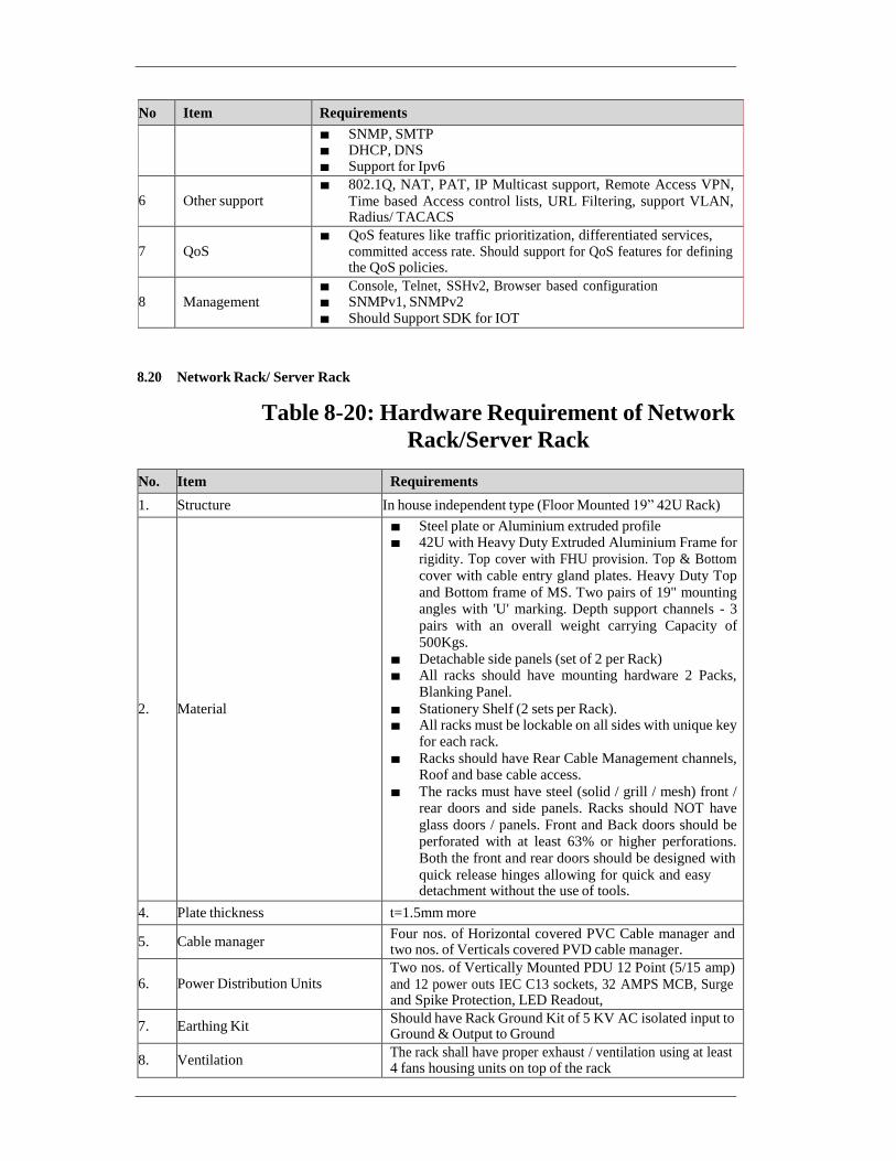
No Item Requirements
■ SNMP, SMTP ■ DHCP, DNS ■ Support for Ipv6
6
Other support ■ 802.1Q, NAT, PAT, IP Multicast support, Remote Access VPN,
Time based Access control lists, URL Filtering, support VLAN, Radius/ TACACS
7
QoS ■ QoS features like traffic prioritization, differentiated services,
committed access rate. Should support for QoS features for defining the QoS policies.
8
Management ■ Console, Telnet, SSHv2, Browser based configuration ■ SNMPv1, SNMPv2 ■ Should Support SDK for IOT
8.20 Network Rack/ Server Rack
Table 8-20: Hardware Requirement of Network
Rack/Server Rack
No. Item Requirements
1. Structure In house independent type (Floor Mounted 19” 42U Rack)
2.
Material
■ Steel plate or Aluminium extruded profile ■ 42U with Heavy Duty Extruded Aluminium Frame for
rigidity. Top cover with FHU provision. Top & Bottom
cover with cable entry gland plates. Heavy Duty Top
and Bottom frame of MS. Two pairs of 19" mounting angles with 'U' marking. Depth support channels - 3
pairs with an overall weight carrying Capacity of
500Kgs. ■ Detachable side panels (set of 2 per Rack) ■ All racks should have mounting hardware 2 Packs,
Blanking Panel.
■ Stationery Shelf (2 sets per Rack). ■ All racks must be lockable on all sides with unique key
for each rack.
■ Racks should have Rear Cable Management channels, Roof and base cable access.
■ The racks must have steel (solid / grill / mesh) front / rear doors and side panels. Racks should NOT have
glass doors / panels. Front and Back doors should be perforated with at least 63% or higher perforations.
Both the front and rear doors should be designed with
quick release hinges allowing for quick and easy detachment without the use of tools.
4. Plate thickness t=1.5mm more
5. Cable manager Four nos. of Horizontal covered PVC Cable manager and two nos. of Verticals covered PVD cable manager.
6.
Power Distribution Units Two nos. of Vertically Mounted PDU 12 Point (5/15 amp)
and 12 power outs IEC C13 sockets, 32 AMPS MCB, Surge and Spike Protection, LED Readout,
7. Earthing Kit Should have Rack Ground Kit of 5 KV AC isolated input to Ground & Output to Ground
8. Ventilation The rack shall have proper exhaust / ventilation using at least 4 fans housing units on top of the rack

8.21 UPS Parallel Redundant
Table 8-21: Hardware Requirement of UPS
No. Item Requirements
1. Input voltage ■ Commercial Power generally but with existing condition of power failure, instantaneous power failure and voltage fluctuation
2 UPS ■ Adequate capacity to cover the System Components at respective location
■ Three 3 hours or longer backup power supply for Equipment in
TIMS-CCC.
■ Ability to shutdown equipment safely when low battery. ■ Ability to start up equipment safely when restoration of AC power.
■ Protection for voltage fluctuation and voltage spike. ■ Output: AC 230 V / 50 Hz sine wave, constant voltage and constant
frequency.
■ Long life battery to meet the Design Life. ■ Output condition shall meet equipment to be supplied by the
Contractor.
■ Applying appropriate measures in order to be available even in
severe environmental conditions outdoors.
8.22 Wi-Fi Equipment
Table 8-22: Hardware requirement of Wi-Fi equipmen
No. Item Requirements
1. Wi-Fi Contractor shall implement industrial grade and rugged Wi-Fi router
device in CCC to support and operational minimum define option:
■ 802.11 − Pertains to wireless LANs and provides 1 - or 2-Mbps
transmission in the 2.4-GHz band
■ 802.11a − an extension to 802.11 that pertains to wireless LANs and
goes as fast as 54 Mbps in the 5-GHz band.
■ 802.11g − Pertains to wireless LANs and provides 20+ Mbps in the
2.4-GHz band.
■ 802.11b − 802.11 high rate WIFI is an extension to 802.11 that pertains
to wireless LANs and yields a connection as fast as 11 Mbps
transmission in the 2.4-GHz band
9 Communication Requirement
Table 9-1: Communication Requirements of TIMS-CCC
No. Requirements
1. ■ Communication requirements between the roadside equipment and the system server of each subsystem are specified in the requirement of each subsystem.
2. ■ Communication for the replication from physical server environment to the cloud environment shall be a fibre network (Broadband Service) provided by a single communication company.
3. ■ C2C (Centre to Centre) Communication between TIMS-CCC and CBS-CCC shall be a fibre network (MPLS VPN) by a single communication company.

10 Installation Requirement
The followings shall be considered while Installing equipment’s at the control center. The Contractor shall obtain approval for installation location/place before installing Console equipment’s and other necessary infrastructure arrangements such as furniture’s, false ceiling, Power, Communication etc. as enumerated in functional requirement. .
■ Conduct installation of the equipment with prudent consideration to earthquake-resistance.
■ Proper space should be secured behind Video Wall for heat releasing and maintenance work. ■ All cables should be installed with proper cable wiring arrangement structure in order not to disturb
the flow line of users.

Chapter 2-2 Requirements of Integrated Traffic
Management System
1 General
The proposed Integrated Traffic Management System (ITMS) shall provide capacity building support to city authorities as per the scope of services described below. Any functionality not expressly stated in this document but required to meet the needs of the Chennai-ITS and to ensure successful operations of the system shall essentially be under the scope of the Contractor without any extra cost to Employer during the Project Period. Following key tasks shall be covered under this initiative:
(a) TIDS cameras including Fixed and PTZ cameras for live video monitoring Integrated with ITMS
system.
(b) Monitor the ongoing activities at the key traffic junctions.
(c) ATCS system monitoring, controlling and analytics required for city traffic as per desire shall take
place from single location.
(d) Facilitate traffic rules enforcement through design, supply, and installation of Red-Light Violation
Detection (RLVD) and speed Limit violation detection (SLVD). Each of these systems shall be
integrated with ITMS system.
(e) Integrate e‐challan system with traffic enforcement cameras, sensors, for automated issuance of
challans and further audit as and when required by the Employer.
(f) System shall collect probe data from CBS system, and ATCC for calculation and alert generation
for city traffic congestion, density and estimated traveling time. In future, the proposed ITMS
system shall be capable to integrate required Probe taxi data or any other probe data.
(g) System shall show all the equipments live location, health status, incidents, SLA monitoring in
integrated way on single screen.
(h) Create a Centralized Management Information System (MIS) as a part of the ITS solution for faster
decision making in traffic emergency such as heavy rain fall, accidents, terrorist attack, VVIP
movements or any other situation as required by the Employer etc.
(i) Cooperate, manage and train the administrative staff and offer back-end support on the operations
of the ITMS using the departmental manpower
(j) To disseminating scalable and analyzed traffic information on connected VMS as well as virtual
VMS locations.
(k) To collected traffic information, flood information, incidents from other projects /Government.
agency to analysis and generate alert for ITS system
(l) Disseminating Traffic information for road user on request and emergency through VMS, SMS,
Website, mobile app.
(m) Disseminating information for external agency, stack holder and government. department.
Contractor shall implement and deliver the following systems and capabilities linked with
ITMS system and shall be controlled and monitored from single location‐
(a) Probe data collection and traffic information dissemination.
(b) Automatic Traffic Counters-cum-classifier (ATCC) System
(c) Adaptive Traffic Signal Control System (ATCS)
(d) Red Light Violation Detection (RLVD) System
(e) Speed Limit Violation Detection (SLVD) System
(f) Traffic Incident Detection System (TIDS)
(g) Variable Message Sign (VMS)

2 System Configuration
Overall system configuration and TIMS system configuration are shown below.
Figure 2-1: Overall System Configuration of CITS

Project

Figure 2-2: System Configuration of TIMS
3 System Functional Requirements
The ITMS platform shall have several functional modules such as Incident Management Module, Information Sharing Module, Probe Processing Module, Enterprise Management and Module Common Function Module as the minimum requirement. The ITMS platform shall be capable of adding additional modules based on the future requirements.
The web site and Mobile application shall be provided as the part of the system. The language
option for web site and Mobile application shall be English and Tamil and upgrade options
shall be provided.
4 Equipment Location
Integrated Traffic Management System will be established at TIMS command and control centre at the Office of Commissioner of Police.
Table 4-1: TIMS CCC Location
No. Location Type Location Name
1 TIMS Command Control Center Office of Commissioner of Police, Vepery
Data Archiving
Storage
(GIS and Business Intelligent Platform)
Op
en
O
pe
n
Op
en
O
pe
n
AP
I
A
PI
AP
I
A
PI
Op
en
AP
I
Info
rmatio
n S
harin
g M
od
ule
Incid
en
t Ma
na
gem
en
t Mo
du
le

4.1 Functional Requirements of ITMS Command Control Software
Table 4-2: Functional requirement of ITMS Command
Control Software
No. Requirements
General Function
1. ■ The proposed software should have functions of GIS and Image Processing along with advance functions such as network analysis, terrain analysis, 3D analysis, change analysis,
etc.
■ The proposed GIS software could be any Industry standard COTS GIS platform and
should be easy to handle, operate, maintain & also train the staff/end users.
■ Software (Application, Database and any other) must not be restricted by the license terms of the OEM from scaling out on unlimited number of cores and servers during future
expansion.
■ The solution should be network and protocol agonistic and provide option to connect
legacy system through API's with either read, write or both options. It should connect diverse on premise and/or cloud platform's and makes it easy to exchange data and
services between them.
■ GUI shall be highly user friendly, self-explanatory and eye catching. It shall provide the sample example wherever it seeks user input and also preserve the history of the inputs. GUI can be made good looking and beautiful by making use of good color scheme and putting functions indicative image (drawing) on button.
■ The customized software for the organization/department should have simple user
interface both for departmental users as well as for citizens with easy navigation and querying facility.
■ The software should support OGC Services such as WMS, WFS, WCS, CSW, INSPIRE,
etc along with GML, KML, etc.
■ The software should support all types of raster formats and services like ERDAS
IMAGINE, ENVI, PIX, DTED, DEM, CEOS, JPEG, JP2, PNG, GeoTIFF, & Web Coverage Service (WCS, OGC standard), Web Map Service (WMS), OGC standard.
■ ODBC compliance enabling interface with RDBMS like Post GRE SQL, Oracle, SQL
server, Access etc. should be available.
■ No proprietary protocol shall be used among the system and device. If any then same information shall be submitted to Employer including Code and related documentation.
Convergence of Multiple feeds/ Services
1. ■ System needs to have provision that integrates various services and be able to monitor and
operate them. The solution should provide scalability option to implement new use cases.
■ System should have capability to source data from other systems implemented within the
city to create actionable intelligence.
■ Contractor shall design & support populating project (static & real-time) data in open data
format and support requirements of developer portal which will be part of the Chennai's
Open Data initiative, which is currently under development.
■ Contractor shall support defining and integrating project data with Namma Chennai App
to support requirements of the Namma Chennai App users.
2. Industry Standards for the Command & Control Center
■ The solution should adhere to the Industry standards for interoperability, data representation & exchange, aggregation, virtualization, and flexibility
■ IT Infrastructure Library (ITIL) standards for Standard Operations Plan & Resource Management.
■ Business Process Model and Notation (BPMN) or equivalent for KPI Monitoring.
■ Platform must have an intuitive data flow-based drag and drop studio, where the data can

be pulled from different connectors and the transformed using pre-build functions or using custom functions
■ Platform must provide a rich set of built-in functions to transform the data from one format to another.
GIS Functions
1. ■ The proposed software should support multiple document interface (MDI), User should be able to create multiple views in single project.
■ The application framework of the software should be such that it should have Dockable /Floating Toolbars, Dockable and Auto Hiding Windows, Unicode Support for
Multilanguage Attributes, Drag and Drop to Rearrange Tools/Toolbars, Create New Toolbars or Menus without Programming, Extend the Applications with Add-ins built
with .NET, Java, or Python, Build New GIS Components with .NET or Java or other
development platforms.
■ The proposed software should have capability to create layer as per the data model defined by the authority. User should be able create table structure as per the requirement
■ The software should have provision for definition of map projection system and geodetic
datum to set all the maps in a common projection and scale.
■ It should have facility to create custom projection using 3 to 7 parameters.
■ It should have the facility to display multiple projection coordinates on map click.
■ The software should provide facility to click on any feature of the map and return a select set of attributes for feature i.e. Identify tool along with pop-up.
■ Software should have rich geo-processing functions such buffer generation, clip, erase,
intersection, dissolve, union, polyline to polygon, etc. It should have facility to perform the spatial intersection analysis like plot area with buffer zone to calculate road-widening
impact on adjacent land.
■ The Software should be able to import / export data from / to various formats like .dwg,,
dxf, .dgn, .shp (shape files), coverage file, .mif (MapInfo), .mdb (GeoMedia),
.gml, .kml, .gpx. , Geo PDF GeoJSON, interlis, GeoRSS, SqlLite etc
■ The proposed software should have function to import / export tabular data such as
.xlsx, .csv, .dbf, etc
■ Support of Coordinate Geometry (COGO) description for GIS objects creation and store in GIS database.
■ Facility to define joins between the two tables (graphic / non-graphic) of the database to
get integrated information in the table and perform GIS analysis.
■ The system should provide the facility to exchange the GIS Data with other platform
applications like Word, and Excel to use GIS data and generate reports like graph and charts
■ The software should have rich display and navigation tools. It should have zoom in, zoom out, fixed zoom in, fixed zoom out, pan, real-time pan, bookmark, Geo link multiple views, swipe, flicker, search by location, crosshair, cursor location value, numeric dump, query cursor, etc. It should have the support of continuous panning i.e., real-time pan.
■ The software should have a module for geo-referencing of vector and raster data.
■ Facility to capture the geometry from the layout maps, building maps by maintaining the coincident geometry i.e. when a new polygon is captured simply by selecting an existing polygon to digitize the common boundary thereby ensuring no slivers or gaps between adjacent area features like parcels.
■ The software should provide a complete set of drawing & editing tools to enable the user to Draw & Modify any or parts of various geographical objects (point, line, and polygon)
on the map.
■ The software should have a topology creation tool to remove the topological errors from vector data.
■ The software should have a provision of hyperlinking the GIS feature as well as its

attribute fields with existing documents, URLs, Images, drawing files, or scanned maps related to that feature
■ The software should have versioning capability for history tracking.
■ The customized application should provide the user facility to make dynamic queries on
GIS GUI. The application should allow users to store and retrieve standard queries used by them in day-to-day operations.
■ The software should allow users to export results to various file formats like EMF, BMP, TIFF, JPEG, PDF, etc.
■ The software should have a map composition/layout tool for printing spatial data at different scales and adjustable print quality.
Integrated User Specific & Customizable Dashboard
1. ■ Should provide an integrated dashboard with an easy to navigate user interface for
managing profiles, groups, message templates, communications, tracking receipts, and
compliance
■ Collects major information from other integrated ITS components/platforms. Should
allow different inputs beyond cameras, such as PC screen, web page, and other external
devices for rich screen layout Multi-displays configurations
■ Use of GIS tool which allows easy map editing for wide-area monitoring (Google map, Bing map, ESRI Arc GIS map, etc.).
■ Should provide historical reports, event data & activity log. The reports can be exported
to pdf or HTML formats.
■ Should provide tools to assemble personalized dashboard views of information pertinent
to incidents, emergencies & operations of the command center
■ GIS Dashboard must have minimum following layers
✓ ATCC Type 1 Layer
✓ ATCC Type 2 Layer
✓ ATCS Layer
✓ RLVD Layer
✓ SLVD Layer
✓ VMS Layer
✓ TIDS Layer
✓ AVL/CAD Layer
✓ PIS Layer
✓ DMS Layer
■ GIS details procured shall include the following data with attributes
✓ Road Network
• City Arterial Road
• Street
• National Highways
• State Highways etc.
✓ Administrative Boundaries
• District and Sub District Boundary
• Town Boundary
✓ Building footprint and names
✓ Point of interest data to include
• Health service (Hospital, Blood Bank, Medical service, etc.)
• Community Services (Fire Station, Police station, Bank, ATM, Education Institute, Govt. Buildings, etc.)

• Business center (Shopping Mall, Market, Commercial complex, etc.)
• Transportation (Bus Stop/Terminal, Parking Area, Railway station, Petrol pump, Metro station, Seaport, Airport, etc.)
• Residential Area (Apartment, Housing society, etc.)
• Road Amenity (Flyover, Foot Over, Underpass, etc.)
■ Should provide dashboard filtering capabilities that enable end-users to dynamically filter the data in their dashboard based upon criteria, such as region, dates, product, brands, etc. and capability to drill down to the details
2 ■ The software should have the capability to process optical satellite data as well as microwave image data etc.
■ The software should support image format such .tif, geotiff, .img, .pix, .hdr, .h4, .h5, DTED, DEM, CEOS, .bmp, .jpeg, etc.
■ The software should have a module for image mosaicing and splitting.
■ It should have Layer stacking to create a composite image from several bands of the
satellite imageries.
■ The software should have an image enhancement module to enhance the imageries. It
should have an enhancement algorithm such as Linear, Logarithmic, Histogram
Equalize, Histogram Matching, Density Slice, Gaussian, Squire root, Tone Balancing
■ The software should have a Natural Color image generation module using NIR, Red, and
Green bands of high-resolution multispectral image data. This module should have the
capability to stretch the natural color image.
■ The change detection module should have the capability of Object Library Creation for Object Identification and Automatic Feature Extraction (AFE).
■ The software should have a function called Dynamic threshold for analyzing change detection using the image. This function is used to categorize the pixels in the input image
based on the threshold value.
■ The application should be highly interoperable with the ability to import and export to a wide range of industry-standard formats including CAD (DGN, DXF, DWG), ArcGIS geodatabases, Geo Media Warehouse, MapInfo, GML (GEOGRAPHY MARKUP
LANGUAGE), XML, SHP, ArcInfo Coverage, ESRI Arc Info Export (EOO), Micro
Station V7/V8, Geo PDF GeoJSON, interlace, GeoRSS, SqlLite, etc.
■ Should be capable of maintaining data history, version management, and conflict
detection/resolution.
■ Should have the capability of centrally managed data, models, tools, maps, and
applications.
■ Should have a geo-processing framework, geoprocessing core analysis functionalities, spatial and statistics analysis functionalities.
■ Application Server must support Time aware data for Trends / Time Series Analysis.
■ Application Server must support network and perform Routing analysis, Service Area
Analysis, etc.
■ Should support database check-in–check out/replication functionalities hence maintaining the parent-child relationship of Master Database.
■ Platform must have the ability to connect to different source systems using varied connection protocols and consume the data that can be either used for ingestion into the platform database or be directly pushed for the visualization layer to be consumed by visualization layer or be exposed as an API to be consumed by 3rd party
■ Platform must have the ability to create connection templates that holds the security
configuration of a source system and this template can be used by different connectors to connect to the source system and receive or consume the data
■ Platform must have the ability to perform both persistent and non-persistent connections
Command & Control Center Components

1. ■ Web server to manage client requests. The client should provide web-based, one-stop
portals to event information, overall status, and details. The user interface (UI) to present customized information in various pre-configured views in common formats. All
information to be displayed through easy-to-use dashboards.
■ Application server to provide a set of services for accessing and visualizing data. Should
be able to import data from disparate external sources, such as databases and files. It should provide contacts and instant messaging services to enable effective, real-time
communication. It should provide a business monitoring service to monitor incoming data
records to generate key performance indicators. It should also provide users to view key performance indicators, standard operating procedures, notifications, and reports, spatial-
temporal data on a geospatial map, or view specific details that represent a city road, building, or an area either on a location map or in a list view. The application server should
provide security services that ensure only authorized users and groups can access data.
■ Analytics functionality can be part of an application server or separate server
Integration with Social Media & Open
1. ■ Should provide integration of the Incident Management application with the social media. Should Provide analytics based on the social media feed, other big data sources as
identified by CSCL/GCC/CTP/MTC
Incident Management Flow Function
1. ■ The application shall be able to provide the management flow, activity, party to be
communicated such as hospital, etc, and report/approved to/by, contact information to the
operator.
■ The application shall make it possible for the operator to confirm the status of the
management flow.
■ All activity shall be logged
■ The application shall make it possible for operators to create/adjust and pre-set process flows.
■ Follow can be added and modified by easy operation by the operator
■ The application shall be able to keep active status from the utterance to resolve the
incident.
■ Should support for sudden critical events and linkage to standard operating procedures automatically without human intervention.
■ Should support for multiple incidents with both segregated and/or overlapping management and response teams.
■ Should support Geospatial rendering of event and incident information.
■ Should support plotting of area of impact using polynomial lines to divide the area into
multiple zones on the GIS maps.
■ Should support comprehensive reporting on event status in real-time manually or
automatically by ITS Equipment
■ The system must provide Incident Management Services to facilitate the management of response and recovery operations.
■ Should provide the facility to capture critical information such as location, name, status, time of the incident and be modifiable in real-time by multiple authors with role- associated permissions (read, write). Incidents should be captured in standard formats to facilitate incident correlation and reporting.
■ The system must identify and track the status of critical infrastructure/resources and provide a status overview of facilities and systems
■ Should provide detailed reports and summary views to multiple users based on their roles.
■ Provide User-defined forms as well as Standard Incident Command Forms for incident management.

■ A Reference Section in the tool must be provided for posting, updating, and disseminating
plans, procedures, checklists, and other related information.
Source Intelligence
1. ■ Source intelligence and collate with the surveillance inputs to alert the responders for
immediate action on the ground.
■ Should extract messages and display them in an operational dashboard.
■ Should be able to correlate the extracted message from the ITS equipment and social
media with existing other events and then should be able to initiate an SOP.
■ Should be able to identify the critical information and should be able to link it to an existing SOP or a new SOP should be started.
■ Should provide notifications to multiple agencies and departments (on mobile) that new intelligence has been gathered through the open source/social media.
Equipment Status
1. ■ Should provide an icon-based user interface on the GIS map to report nonfunctional
devices.
■ Should also provide a single tabular view to list all devices along with their availability status in real-time.
■ Should provide User Interface to publish messages to multiple devices at the same time.
Event Correlation
1. ■ Command & Control Center should be able to correlate two or more events coming from different subsystems (incoming sensors) based on time, place, custom attribute and
provide correlation notifications to the operators based on predefined business and
operational rules in the configurable and customizable rule engine.
Standard Operations Procedures
1. ■ Command & Control Center should provide for authoring and invoking an unlimited
number of configurable and customizable standard operating procedures through a
graphical, easy-to-use tooling interface.
■ Standard Operating Procedures should be established, approved sets of actions are the best
practices for responding to a situation or carrying out an operation.
■ The users should be able to also add comments to or stop the SOP (before completion).
■ The users should be able to edit the SOP, including adding, editing, or deleting the
activities.
■ There should be provision for automatically logging the actions, changes, and
commentary for the SOP and its activities, so that an electronic record is available for
after-action review.
■ Platform must provide the ability to use the outbound adapters as outbound tasks that can be to trigger actions or send data or invoke the 3rd party devices or 3rd party application
■ Platform must provide the ability to assign SOP templates to an event that is raised
■ Platform must provide the ability to approve or reject an SOP from getting executed for
an event that is raised
■ Platform must provide an ability to trigger multiple tasks at the same time
■ Platform must provide ability to trigger external APIs as part of SOP steps.
■ The SOP Tool should have the capability to define the following activity types:
✓ Manual Activity - An activity that is done manually by the owner and provides details
in the description field.

✓ Automation Activity - An activity that initiates and tracks a particular work order and selects a predefined work order from the list.
✓ If-Then-Else Activity - A conditional activity that allows branching based on specific criteria. Either enter or select values for Then and Else.
✓ Notification Activity - An activity that displays a notification window that contains an email template for the activity owner to complete, and then sends an email
notification.
✓ SOP Activity - An activity that launches another standard operating procedure.
Key Performance Indicator
1. ■ Command & Control Center should be able to facilitate measurement or criteria to assay
the condition or performance of departmental processes & policies.
■ Green indicates that the status is acceptable, based on the parameters for that KPI, no action is required.
■ Yellow indicates that caution or monitoring is required, action may be required.
■ Red indicates that the status is critical, and action is recommended.
Reporting Requirements
1. ■ Command & Control Center should provide easy to use user interfaces for operators such as Click to Action, Charting, Hover and Pop UPS, KPIs, Event Filtering, Drill down capability, Event Capture, and User-Specific Setup
■ The solution should generate Customized reports based on the area, ITS equipment type or periodic or any other customer reports as per the choice of the administrators
■ Reports shall support vernacular language.
BI Analytics
1 ■ BI Analytics capability must be in-built in the platform without usage of additional COTS product or additional integrations
■ Platform must be capable of providing slice and dicing capability using the visual representations and actions available in the dashboard widget system
■ Platform must be capable of analyzing the data coming from different domains and the
different sub-systems
■ Platform must have user friendly BI tool for manual as well as automated analytics.
■ Platform must be capable of mashing the data from different domains and different sub- systems, and thus provide cross-domain analysis capability
■ The Analytics engine must be an artificial intelligence-based module to maximize business value through advanced machine learning capabilities. The machine learning
capabilities must aid in operations management and result in better outcomes.
■ Analytics Engine must have automatic Model training and retraining capability and should not have any manual intervention
■ Analytics Engine must be able analyze the simulated data, train the models using
simulated data and predict the possible outcomes
■ Based on data analyzed from multiple data sources of the city, Analytics Engine must
provide recommendations which can derive value/outcomes in terms of revenue optimization and cost savings for the city.
Authentication
1. ■ Should have the ability to respond to real-time data with intelligent & automated decisions
■ Support LDAP authentication mechanism
■ Provide policies using separate dimensions of authorization criteria like Traditional static Access Control Lists that describe the principals (users and groups) access to resources and the permissions each of these principals possesses.
■ Various users should be able to access the system using single sign-on and should be role

based. Different roles which could be defined (to be finalized at the stage of implementation) could be Administrator, Supervisor, Officer, Operator, etc.
■ Apart from role-based access, the system should also be able to define access based on location.
■ Rights to different modules / Sub-Modules / Functionalities should be role based and proper log report should be maintained by the system for such access.
Situational Awareness COP (Common Operational Picture)
1. ■ The Command & Control Center Application should be able to combine data from various sources and present it as different views tailored to different operator's needs.
■ The Command & Control Center Application should automatically update the information
based on alarms and incidents that are presented to it via the business rules engine. The
polling and Command & Control Center Application database refresh cycle shall be configurable to match the status of the situation (whether there is an emergency or crisis
or just monitoring only).
■ Common Operational Picture should comprise of a comprehensive view of the incident or
a group of related incidents as on a specific date and time which should include but not be limited to the following:
✓ Task’s assignment and their status
✓ Agencies involved
✓ Resources deployed
✓ Incident status across relevant parameters of the incident e.g., congestion due to accident and traveling time affect or any other unusual situation as required by the
Employer
✓ A timeline view of the situation
Suggested actions from the system with their status
Alarm Display
1. ■ Should have an ability to display alarm condition through visual display and an audible
tone
■ Should have an ability to simultaneously handle multiple alarms from multiple workstations
■ Should have an ability to automatically prioritize and display multiple alarms and status conditions according to pre-defined parameters such as alarm type, location, Equipment, severity, etc.
■ Should display the highest priority alarm and associated data/video in the queue as default,
regardless of the arrival sequence
■ Disseminating information on VMS
Historical Alarm Handling
1. ■ Should have an ability to view historical alarm details even after the alarm has been
acknowledged or closed.
■ Should have an ability to sort alarms according to date/time, severity, type, and Equipment ID or location.
Security
■ The architecture must adopt an end-to-end security model that protects data and the Infrastructure from malicious attacks, theft etc. Provisions for security of field equipment
as well as protection of the software system from hackers and other threats
■ shall be a part of the proposed system. The evidence of Infraction should be encrypted and
protected so that any tampering can be detected.
■ Ease of configuration, ongoing health monitoring, and failure detection are vital to the goals of scalability, availability, and security and must be able to match the growth of the
environment.

■ The system should have secure access mechanism for validation of authorized personnel.
■ Roles and Rights of users should be defined in the system as per the requirements of the
Employer.
■ Deletion or addition and transfer of data should only be permitted to authorized users.
■ A log of all user activities should be maintained in the system.
4.2 Functional Requirements of Incident Management Module
The functional requirements of the incident management module are shown in the table below.
Table 4-3: Functional Requirements of Incident
Management Module
No. Requirements
Road and Traffic Monitoring Function
1. ■ The application shall be able to display the monitoring display of all TIMS subsystems.
■ The application shall be able to automatically display the real-time traffic information
(congestion level information by color-coded) in the map-based view (schematic map
view and GIS map view) on the video wall screen
■ The application shall be able to notify the occurrence of the incident by showing the alert or message on the display. the incident information such as type of incident, location, etc.
graphically in the map-based view on the video wall screen.
Incident Registration Function
1. (1) Automatic Incident Registration
■ The application shall be able to automatically receive the traffic incident information detected by TIDS and heavily congested information by Probe System.
■ When the incident information is received, the application shall be able to notify the
occurrence of incidents to operators displaying them on the map or making an alert.
■ When the incident information is received, the application shall be able to automatically
create the pre-register data sets including incident type, location, time and serious level,
etc., and show them to operators. The application shall be able to enable operators to
modify the pre-register data sets as necessary before completing the registration.
■ The Contractor shall consider the integration of the incident data from the ICCC system and CPRR system in the above-mentioned automatic data registration function.
2. (2) Manual Incident Registration
■ The application shall be able to manually register incident information collected through helpdesk, the notification from relevant agencies and news/websites as follows. ✓ Lane closure, accident, fallen object, construction work, stalled vehicle, pavement
problem, adverse weather, fire nearby, etc.
■ The application shall be able to provide a useful user interface for manual data registration
such as pull-down menus etc. to help operators.
■ The application shall enable operators to manually register various data such as traffic,
weather, construction, etc. from the ICCC system and CPRR system.
VMS message creation
1. ■ If an incident is detected through another system, the system shall send an alarm to the VMS system. VMS system shall then create a warning message indicating the location,
type of incident and action to be taken.
■ The application shall be able to create a VMS message but can be confirmed by the
operator or authorized person to show by VMS.
■ The word which is frequently used such as “accident”, “congestion”,” construction work”,
“slow down” and so on are used to compose a message combination by selection. They

contain words indicating location, event, and instruction.
■ The operator can select one of the ready-made messages stored.
■ Any message which the operator cannot select; the operator can create any message
through the keyboard.
VMS Priority Management Function
1. ■ The application shall be able to set the target link and area of each VMS for information
provision.
■ The application shall be able to automatically make a priority on the incident information
to be provided by VMS based on the seriousness of incidents and the distance between the incident location and the VMS locations.
■ The application shall be able to automatically transmit the incident information to be
displayed on the VMS based on the pre-defined priority.
Traffic Situation Analysis Function
1. ■ The application shall be able to automatically associate the certain traffic situation such as traffic congestion etc. and the causal factors from identified traffic incidents.
e.g., “Traffic Congestion” caused by “Car Accident”
Incident Management Flow Function
1. ■ The application shall be able to provide the management flow, activity, party to be
communicated such as hospital etc., and report/approved to/by, contact information to the
operator.
■ The application shall make it possible for the operator confirm the status of the
management flow.
■ All activity shall be logged
■ The application shall make it possible for operators to create/adjust and pre-set process flows.
■ Follow can be added and modified by easy operation by operator
■ The application shall be able to keep active status from the utterance to resolve of the
incident.
4.3 Functional Requirements of Information Sharing Module
The functional requirements of the information sharing module are shown the table below.
Table 4-4: Functional Requirements of Information
Sharing Module
No. Requirements
Data Integration with Related Systems
1. ICCC System (GCC)
■ The application shall be able to collect required data from ICCC shared location and
integration at data level.
■ The application shall be able to receive the Disaster information, Flood information etc. from ICCC System.
■ The application shall be able to provide the traffic information to the ICCC System.
2. CPRR
■ The application shall be able to connect to the CPRR System for the data integration.
■ The application shall be able to receive the traffic information (ATCC, Travel time,
accident etc) from CPRR Server.
■ The application shall be able to provide the traffic information to CPRR Server.

3. ■ The application shall be capable to exchange the data with any other Agency as and when required by the Employer
■ The protocol for integration with related system shall be according to the certified standard in India approved by Engineer.
Information Sharing with Related Agencies
1. The application shall be able to disseminate the archived traffic data to any related
governmental agencies. In order to achieve this, the system shall generate the exchange data
in standard data format such as XML etc..
2. In order to use historical traffic data /information accumulated in the TIMS CCC, Information
available can be shared with other designated public agencies such as PWD, Tamil Nandu
Highway Department, NHAI and any other relevant agencies as per the protocol set by the Employer. This data shall be made available on application through a web portal or via an API service .
3. Contractor shall ensure that the application developed is easily to share data and collect data.
The standards should at least comply with the published e-Governance standards, frameworks,
policies and guidelines in India.
Traffic Information Provision to Road Users
1. The application shall provide road, traffic and other traffic related information collected and processed in the probe processing module to road users in the graphical way via an internet application. The Contractor shall propose the Mobile application and the portal web site for
this purpose.
2. A map-based and easy-to-use interface shall be provided. It shall display a consolidated view
of city traffic condition including the traffic status, events and weather conditions, symbolic facility, major junction etc.
3. The map-based display shall cover the entire city and be able to enlarge individual locations on the map when selected. The enlarged view shall be able to display all the details for each
selected location. The information to be displayed on the map and the enlarged view shall
include but not limited to the following.
■ Traffic information on map (congestion Level by color-coded)
■ Travel time between selected locations by user
■ Event information on map (Accident construction, event etc)
■ Traffic regulation on map (Closure of load, etc)
As for the event information, when clicking the mark of the event, then detailed information shall be shown in the display.
Data Analysis
1. Statistical Analysis
Historical traffic data including ATCC, Probe analyzed data, traffic status, weather condition, construction condition, regulation and incident etc for every road segment is accumulated in database as a Big Data for analyzing. This data is delivered via a product called Traffic Stats, available through a web portal or via an API service.
Application shall provide a huge resource for Authorities and planning organizations to understand baseline conditions, evaluate the impact of changes to road policy, road infrastructure or travel demands over time.
The Contractor shall propose an effective analysis tool in the Technical Proposal.
2. Evaluation of Effectiveness
Evaluation of effectiveness is to analyze the future road situation by considering alternative
possible scenarios.
The application shall make it possible for operators to set road traffic plans (ex. to help their decision making for newly installation of CITS Project facilities such as VMS etc. or effect

of Traffic Diversions or allowing U- turns in a Junction. etc ) in the system. The application
shall be able to analyze the effects on the road traffic situation and generate the several scenarios on improving the traffic control accordingly.
For example, the output of the evaluation of effectiveness of RLVD is that after RLVD implementation how violation has come down, corridor wise how it varies, which intersection
violation is high, is the system meeting the KPI we defined, etc.
Data Archive
1. Historic traffic data including ATCC, Probe analyzed data, traffic status and incident for every road segment is accumulated in database as a Big Data for analyzing. This data shall be made
available on application through a web portal or via an API service.
Application shall provide a huge resource for Authorities and planning organizations to understand baseline conditions, evaluate the impact of changes to road policy, road
infrastructure or travel demands over time.
Items of data to be archived are as follows:
(1) Traffic Data collected by ATCC 2 (Traffic classification data)
(2) Traffic Data processed by Probe System (Link based/section-based traffic data)
(3) Incident Data registered by Operators (Incident type, location, time etc.)
(4) Displayed Data on VMS (Effective factor for traffic such as weather information,
regulation, construction etc)
(5) Traffic Data collected by ATCS
The data shall be archived in the local data storage.
The data shall be archived for at least 10 years
The data shall be escaped to another HDD periodically (once a month at least) by the O&M
Contractor for a backup.
4.4 Functional Requirements of Probe Processing Module
The functional requirements of the probe processing module are shown the table below.
Table 4-5: Functional Requirements of Probe
Processing Module
Requirements
Basic Function
1. The system shall be capable of receiving bus location data from CAD/AVL system in real-
time in the protocol, format and timing as specified by CAD/AVL. And ATCC system
The probe server shall have enough processing power and storage capacity to handle the bus
location data, ATCC data and produce required traffic condition information in a timely manner without delay.
The system shall be able ready to integrate taxi probe or any other required probe data in later
stage of project.
The system shall have a digital road map database of the area covered by MTC bus service in the format suitable for processing bus location data and creating traffic condition information.
In the digital road map data, road network shall be divided into links. Link shall be the smallest unit comprising the road network having uniform characteristics for road traffic. Separate link shall be defined for road link section in opposite direction.
The location of bus stops shall be considered in the processing of the bus location data and in
such a way to minimize the effect of delay of bus caused by boarding and alighting operation at bus stops or in depo during nonoperational mode.
Tracking Data Receiving Function

2. The bus location data is generated at an interval of 10 seconds in each GPS device on board
bus. The probe system shall receive all bus location data as they are sent from buses. The data includes the following items:
■ Device ID,
■ Bus type,
■ Location (Longitude and Latitude),
■ Date & time of data,
■ Bus route number,
■ Speed
More detailed structure of the GPS data will be provided to the Contractor.
Data Validation Function
3. The system shall scrutinize the data received and any abnormal data such as data without time stamp, data value outside of the range, and data with longitude and latitude outside of the bus
service coverage area shall be removed from the data.
Map Matching Function
4. The system shall have map matching function to project the location of bus onto the nearest
point along the bus route. If the distance between original point and projected point is longer than the pre-set threshold, the data shall be disregarded. The system shall have multiple
thresholds to be applied to the different location along the bus route such as central business district and suburbs.
Determination of Moving Direction Function
5. At every traffic condition calculation cycle, the system shall process a set of location data
received since the last calculation cycle and re-arrange the data in the sequence of the time stamp in the data. Then the system shall determine the direction of movement to segregate the data of opposite direction.
Link speed calculation function
6 Vehicle speed of link shall be calculated using the location data of same vehicle. If there are two or more sets of data of the same vehicle in a link, vehicle speed shall be calculated using
the first and last data within the link. If there is only one set of data, the data at upstream link shall be used to calculate the speed. If there is no data in a link, vehicle speed shall be marked
as “not available”. In calculating vehicle speed, the distance along the road alignment shall be
used and the linear distance between two points shall not be used unless link is a straight section connecting the two points. The system shall not use the speed data sent from the GPS
device.
The speed data shall be assigned with a time slot stamp based on the time when the location
data is recorded by GPS device. This is necessary to process the series of data in correct order
and time, as they are received in wrong sequence due to delay in data communication based
on mobile network.
Mean link speed and link average travel time function
7 The vehicle speed data of the same link and same time slot shall be processed, and average speed shall be calculated. The average speed shall be the harmonic mean of the speeds.
Likewise, average travel time of each link shall be calculated using the link length and the
average speed calculated.
The number of data used to calculate the average speed shall be recorded together with the
average speed data to indicate the number of data used for the calculation. It shall be possible
to exclude the link with the number of data fewer than required in the calculation of link section congestion level and link section travel time described below.
Link Section Congestion Level Function
8 Congestion level of each link shall be determined by comparing the average speed with the
thresholds. Traffic condition shall be classified into three levels; no congestion, congested, heavily congested using two thresholds that separate the congestion levels. The threshold shall

be a system parameter and adjustable.
Traffic condition of the link section shall then be determined based on the link congestion
level. The procedure shall consider the length and location of the links comprising the section.
The application shall be able to create event of heavy congestion by probe system in
consideration of traffic data at intersection by ATCS.
Link Section travel time Function
9 The system shall calculate the travel time of link section based on the travel time and length
of links comprising the link section. The link section for congestion level and link section for
travel time shall be defined independently each other.
Supporting Function for Traffic Planning Function
10 Objectives:
This function is offering visualizing data by using historical data from probe system.
To assist clear and fast understanding, historical data should be offered with visualization.
Functions:
Calculating the speed and travel route using probe data.
Calculating and display as following table Between two intersections using probe data.
Item Contents Graphic List
Traffic condition
Current average speed (between two intersections)
Number of vehicles per unit of time
Average time of passing intersection
Congestion level of intersections
Average travel time of sections
Ranking of data (duration time, number of vehicles)
ordered by parameter (time{On Peak, Off Peak}, day{Weekday, holiday, day}, duration{1 month, 3 month, a half year, one year}) etc.
Average travel time of radiation direction

Prove Car Data Processing
Prove Bus Data Processing
START
GPS data reception
Data validation Error
Normal
Map matching
Erroneous data? Yes
No
Store map matched position data
Multiple of 5 min? Yes
No
END
Note: Link: Unit for GPS data processing
Congestion link: Unit for congestion level expression Travel time link: Unit for travel time calculation
Figure: Probe Data Processing and Congestion Analysis Flow and Algorithm
Display Function
11 It shall be possible to display in real-time link section speed as determined by the processing described above on the operator console and in printed form. Both numerical and graphical
presentation of the data shall be provided. The data on the display shall be automatically
updated as the traffic condition is updated.
Data Storage and Retrieval Function
12 All data transmitted from the MTC bus probe system and processed data in the TIMS shall be recorded and stored in the probe server for analysis and future usage. The raw bus location
data sent from GPS device and processed location data after map matching shall be kept for three (3) months, while 5-minute link, speed, link section congestion level and link section
travel time data shall be kept permanently.
Data retrieval and presentation software shall be provided that shows the original location data, location data after map matching, link section congestion level and link section speed data. Graphical presentation of historical section congestion level and section travel time data such as hourly variation and daily variation shall also be available.
Traffic volume information edited and processed is counted in 1 hour, day, month, and saved for a certain period (over 1 year) file. Data older than the retention period will be deleted in
order of old data, and old data can be stored in the storage device etc. of the TIMS Server. In
addition to the above data, it should also store information necessary for system operation. The saved information should be able to provide file output (MS Excel etc.).
Sub-system Data Interval/Timing
Probe system Bus location data received Upon reception
Bus location data after map matching Upon processing
Link speed 5 min.
Link Section congestion level 5 min.
Link Section travel time 5 min.
For all probe car data of same vehicle: Determine moving direction
Calculate speed at each link
Assign time stamp
For all links:
Retrieve speed data of same link with same time slot stamp
Calculate harmonic mean speed and average travel time at each link
For all congestion link:
Retrieve link speed data of same
link and same time slot. Calculate section average speed Determine congestion level
For all travel time sections:
Retrieve link speed data of same
link and same time slot.
Calculate section average travel time
Calculate travel time of section

Monitoring Function
13 The information monitoring shall be map based (Schematic map and GIS map) interface and as well in the form of a list. The schematic map-based display shall cover the entire GCC area
and be able to enlarge individual locations on the map when selected. The enlarged view shall be
able to display the details for each selected location. The details displayed shall cover not be limited to the contents described in the Table below.
Item Contents Graphic List
Traffic condition
Current average speed (link section)
Current travel time (link section)
Probe data Probe data
Location and speed level of time period specified
Parameter Parameters for viewing and editing
Traffic condition
Current average speed (between two intersections)
Number of vehicles per unit of time
Average time of passing intersection
Congestion level of intersections
Average travel time of sections
Ranking of data (duration time, number of
vehicles) ordered by parameter (time {On Peak, Off Peak}, day{Weekday, holiday, day}, duration{1 month, 3 month, a half year, one year}) etc.
Average travel time of radiation direction
Reporting Function
14 The Probe Server shall publish / print as a minimum the reports listed below. The reports shall be
produced as pre-scheduled or on-demand by system operator. It shall be possible to produce the
reports in a portable file format.
Item Contents
Traffic conditions Daily report containing hourly link sectional average speed Monthly report containing daily link sectional average speed and that of the day of the week
Operation and error log List of roadside equipment those are operational or malfunctioned Error record
Data Transmitting Function
15 Following data processed in the Probe Server shall be stored at an interval of 5 minutes in the
database of Traffic Information System for total system management.
■ 1-minute link sectional average speed
■ “n” minutes link sectional average speed (default “n” = 5 minutes)
■ Traffic congestion analysis results with parameters
■ Travelling time in each link
■ Travelling speed in predetermined link section with parameters
■ Equipment operational status

4.5 Functional Requirement of Common Function Module
Table 4-6: Functional Requirement of Common
Function Module
No. Requirements
Solution and Platform
1. ■ The software/Application must not be restricted by the license term of OEM from scaling out on unlimited number of cores and servers during future expansion for application,
database any other.
■ The platform should be able to normalize the data coming from different devices of same type Application servers and provide secure access to that data using data API(s) to
application developers/external agencies
■ System shall have the provision for integration of various services and be able to monitor them and operate them. The solution should provide option to integrate existing deployed solution by City and need to provide scalability option to implement new use cases.
Standard for Application
2. ■ System shall have the provision for integration of various services and be able to monitor
them and operate them. The solution should provide option to integrate existing deployed solution by city at data level and need to provide scalability option to implement new use
cases.
■ System shall have capability to source data from various system existing in Chennai city for traffic and incident information
Dashboard
3. ■ Collect major information from other resource for analysis and show on map (Schematic
map and GIS map)
■ Multi-displays configurations
■ The system should be able to show, create, assign, track and report task life cycle automatic
for detected incident.
Information Monitoring
4. ■ The purpose of ITMS is to have an integrated view of all the applications related to traffic and
enforcement undertaken by Chennai Traffic Police (CTP) and line department with the
focus to serve as a decision support engine in day-to-day operations or during exigency
situations.
■ ITMS shall enable different systems and departments of Chennai to monitor and utilize
information of other departments for delivering services in an integrated and more efficient
manner.
■ ITMS shall Integrate all subsystems of TIMS to a central map of Schematic map and GIS
platform.
■ ITMS shall provide real time dashboards, visualizations, KPIs, historical trending,
analytics and other intelligent features to facilitate city operations analysis by. It provides
alarm features for immediate notification to TIMS level in case critical events occur in the
city and Manage event & incident data.
■ ITMS comprises a centralized integrated dashboard for entire Chennai city for the
reporting and viewing of all the project components and key performance indicators of
systems through a single interface. All information collected & saves into centralized
database & used this information for city administration in a combined platform to view
whole city in one go with the measurable parameter.
■ ITMS must view traffic data monitoring, weather data monitoring, various messaging
signs control, incident detection, incident response,
■ ITMS shall provide a holistic and real time view of all city operations on a video wall

along with individual views on operator workstations. It enables monitoring, control, and
automation of various city operations in order to ease and organize city operations.
■ ITMS must show the use cases such as Traffic congestion, Traffic diversion, Signal
Priority, accidents & Incidents, user information dissemination, all types of defined
Violations such as Red light, stop line, unauthorized U-turn, wrong direction, unauthorized
stopping, signal jumping, Speed violations etc.
■ ITMS must show the warning information such as high traffic congestion, critical accident
zone etc. The application must seed the vehicle position tracking, Geofencing & alert for
over speeding vehicle as well as Red-light violating vehicle.
■ ITMS must be capable to view dashboard having customized displays, current alarms,
meaningful analysis, real time and historical reporting using Business Intelligent (BI)
tools. The Data analytics/BI tool should have ability to analyze the useful information and
sharing it with general public.
■ ITMS must be capable of Forward-looking decision making – BI and analytics tool
provide the predictive and forecasting capabilities which can help department in forward
looking policy and decision making.
■ ITMS must be Customizable and programmable Event Response Mechanism to manage
all the Event Response Mechanisms and must be customizable based upon functional
parameters like criticality, region, access, automatic/manual etc. but not limited to these
four. Dashboards generated by the system (functional / technical) must be customizable
based upon the user’s requirements. The operator system must remember the edits done
by the user to his/her own dashboard when he/she logins next time in the system without
disturbing the main view.
■ The ITMS application must have capabilities to show the Hot Calls alert. Once a Location
of the incident is marked in the map, the operator must have the facility to see for various
'Location of Interest (LOI)' in the vicinity of an event location like nearest Hospital, Blood
Bank, Fire brigade, etc.
■ All services of various solutions available on single platform.
■ Safe Secure and CITS operation with Alarm and Events Notification.
■ Map based Operation and Response.
■ Minimal human intervention for operation.
■ Provide support for decision making with data with graphs.
■ Predefined and customized SOPs to manage city civic operation
GIS Platform
1. One of the goals of the Traffic and Transport is to create a single interface to show integrated view on a GIS platform. GIS platform shall have high quality map view, and which shall
support multiple level of layers. GIS platform shall be customized to provide clear view to the stakeholders.
■ Use GIS system as a backbone for the Chennai traffic network.
■ Collaboration of various city stakeholders & departments together and to have a connect and engagement via a common GIS window for all operations
■ Use GIS as spatial planning and analysis for various operation within city
■ Use GIS as a Decision support system to prioritize actions
■ To have a location-based services to citizens of Chennai for better transparency & quick actions
■ GIS based spatial and non-spatial queries for citizens and administrators and departmental stakeholders
■ GIS map data can be updated timely by easy operation (GIS Map data to be provided by
another party. Cost for update shall be paid by the Contractor.

Database Management
1. ■ The ITMS platform shall store the raw and processed data in a database management system (DBMS) for statistical use in traffic management and road planning. The system
shall have one centralized database for managing the entire System. Parameters such as
type, quantity, and time period of data to be stored in the database shall be configurable. All data shall have a time stamp of recording.
■ The Contractor shall provide the licensed latest version of SQL based Relational Database Management System (RDBMS) such as Oracle, SQL Server, DB2 and/or equivalent as part of the contract. The Contractor shall submit the detailed database architecture as part of the Technical Proposal.
The Contractor shall provide the database on status of all equipment. Items to be
monitored are as follows:
live monitoring (Common)
Message displayed on VMS (VMS system)
Data Collection
■ ITMS shall have feature of data completeness in case any data is missing or did not
synchronize on server due any malfunction then system shall be generating alert and clearly
mention on reports and log as “Data Incomplete”.
■ Transaction number, incident number, Image, Video and Log number etc, shall be in
sequency and unique after go live, It also shall be sync with server and always generate at LPU level.
System Monitoring
2. ■ The ITMS platform shall have a system management function to monitor the operational
condition of roadside equipment and sub-system equipment. The system management
Sub-System Storage Data Interval/Timing
ATCC-1 System
Traffic volume (small vehicles) 5 Min./ 1Hour/ 24 Hours
Traffic volume (large vehicle) 5 Min./ 1Hour/ 24 Hours
Average speed 5 Minutes
Equipment status Upon status change
ATCC-2 System
Traffic volume (all types specified) 5 Min./ 1hour/ 24 hours
Average speed 5 Minutes
Equipment status Upon status change
Probe System GPS data Upon reception
Average speed at each link/section 5 Minutes
Number of data for each link/section 5 Minutes
VMS System Message display log Upon display change
Manual input operation log Upon manual operation
Equipment operational status Upon status change
ATCS System Traffic data collected by detector, including Que length, Speed and occupancy Que length, Average Speed
5 Minutes
RLVD System Violation detail with evidence, Log, Vehicle Image & video,
5 Minutes
SLVD System Violation detail with evidence ,Log, Vehicle Image & video ,
5 Minutes
TIDS System Incident Detected including ,Alert, evidence, Logs
1 Minutes
Others Access history of Web Upon access

function shall monitor the operation status of all the sub-system components.
■ This function shall consolidate the status monitoring of each sub-system component, present the status to operators and record the system operation. When any abnormality or
malfunction is detected, the ITMS platform shall issue an alarm providing the type and
location of the failure so that remedial action can be taken. The event shall be recorded in the sub-system operation log. Database storage shall have a capacity of 2 years for
recording the operation log.
■ Call log function, SLA calculation function and reporting function shall be provided.
Network Management and Control
3. ■ The network management function shall be provided to the system and the function shall continuously monitor the Level 2 switch and Level 3 switch using Simple Network
Management Protocol (SNMP). In case of identification of a malfunction, network
management system shall issue an alarm to the operator console and at the same time store the malfunction record in the network operation log.
■ Database storage shall have a capacity of 2 years for recording the operation log.
■ SLA calculation and reporting function shall be provided.
Parameter Monitoring and Modification
4. ■ Various parameter exists in TIMS to define the system configuration and process gathered
data. These parameters shall be configurable or adjustable to redefine the system configuration and tune the system operation. The Central Server shall be provided with
parameter monitoring and modification function through the screen forms. In order to
prevent inadvertent modification of parameter, access level shall be assigned to the parameter and the system parameters that defines the system configuration shall be given
the highest access level.
■ Each server shall have the same parameter monitoring and modification function of the parameter used for each sub-system. Means shall be provided to prevent contradictory parameter setting by different servers. Modification of the system parameters shall be
possible only through the ITMS platform. However, the parameter of the roadside equipment shall be modified through each server.
Report Compilation and Printing
5. ■ The ITMS platform shall have a reporting functionality by which various daily, monthly,
and annual reports can be printed.
■ The reports shall be produced in two modes, automatic and on-demand. In automatic mode, each report shall be printed automatically at the specified time and in on-demand
mode, report is printed when the operator requests for it.
■ The data storage period is assumed to be about 10 years, and it can be transferred to a storage device for storage. In addition to the above data, it also stores information necessary for system operation. It is assumed that the saved information can be output (MS Excel etc.) from the operator console.
■ The reports shall be provided in vernacular language.

4.6 Functional Requirement of Enterprise Management System (EMS)
Table 4-7: Functional requirement of Enterprise
Management System (EMS)
No. Requirements
ENTERPRISE MANAGEMENT SYSTEM (EMS)
Network Management and Control
1 ■ The network management function shall be provided to the system and the function shall
continuously monitor the Level 2 switch and Level 3 switch using Simple Network
Management Protocol (SNMP). In case of identification of a malfunction, the network management system shall issue an alarm to the operator console and at the same time store
the malfunction record in the network operation log.
■ Database storage shall have a capacity of 2 years for recording the operation log.
■ SLA calculation and reporting function shall be provided.
■ The proposed system shall support multiple types of discovery like IP range discovery –
including built-in support for IPv6, Seed router-based discovery, and discovery whenever
new devices are added with the capability to exclude specific devices.
■ The proposed system shall support the exclusion of specific IP addresses or IP address ranges.
■ The proposed solution shall provide a detailed asset report, organized by proper naming of
all devices, listing all ports for all devices. The proposed system shall provide sufficient reports that identify unused ports in the managed network infrastructure that can be
reclaimed and reallocated.
■ The proposed solution shall determine device availability and shall exclude outages from
the availability calculation with an option to indicate the reason.
■ The proposed solution shall provide the box root cause analysis.
■ The proposed solution shall have an integrated user-friendly application.
■ The proposed solution shall include all required licenses.
■ The proposed solution shall provide real-time monitoring of the entire network
infrastructure and shall allow users to easily navigate with a graphical interface and easy- to-use network management tools.
■ The proposed solution shall provide at a minimum, event alert via the existing Microsoft
Exchange Server email or pop-up alarm or export to CSV.
■ The proposed solution shall automatically generate reports on a daily, weekly, and monthly
basis in formats including graphs, bar charts, distribution, and summary. The system shall
be capable of printing out reports and also exporting the reports to other systems or web
servers.
■ The proposed solution shall display a simple map of the whole network as a tree and shall have the option of direct selection of objects. The system shall provide a navigation tree to
display the current alarm status of each subnet. All the systems shall support PAN/ ZOOM
feature and shall have all the devices visible in one window along with the provision for these two features
■ The proposed solution shall provide polling agents to upload status, changes, or alerts of
the local devices attached with the Ethernet enabling devices.
■ The proposed solution shall provide real-time Management Information Bases (MIBs)
displays and shall provide the MIB variable data in tabular or graphical format. The MIB
displays shall provide various expressions like utilization, percentage errors, and volume
■ The proposed solution shall provide features for security and accountability and shall
generate a log file for any user access to configuration or platform changes.
■ The proposed solution shall be capable of managing any SNMP/ICMP device from any

vendor.
■ The proposed solution shall support SNMPV1, SNMPV2C, and SNMPV3 and shall automatically discover and poll SNMP and ICMP devices.
■ SNMP traps for all IP-enabled devices shall be provided by the respective product manufacturers.
■ The proposed solution shall allow notifications to be automatically sent to phones, offsite workstations, etc. for efficient response.
■ The proposed solution shall monitor as a minimum the base station unit and the subscriber station units along with other IP-enabled equipment that is being provided as part of this
Project.
■ The proposed solution shall allow for providing different levels of security access i.e., viewing, logging and managing.
■ The proposed solution shall allow for the display of different colors for the links including
red, green, orange, yellow to show the status of the links and the connected devices
■ The operation of the NMS shall be tested while the backbone network is under 30%
network utilization.
■ The proposed solution must provide an interface for IT helpdesk personnel to create guest credentials.
■ The proposed solution shall be supplied with a server with Windows or Linux-based OS
(latest) or later.
Service Level - Monitoring, Management, and Reporting
2 ■ The proposed service management system shall provide a detailed service dashboard view indicating the health of each of the components and services provisioned as well as the SLAs
■ The system shall provide an outage summary that gives a high-level health indication for each service as well as the details and root cause of an outage.
■ The system shall be capable of managing IT and Non-IT resources in terms of the business
services they support, specify and monitor service obligations, and associate
users/Departments/ Organizations with the services they rely on and related Service/Operational Levels Agreements. Presently, services shall include E-mail, Internet
Access, Intranet, and other services hosted.
■ SLA violation alarms shall be generated to notify whenever an agreement is violated or is in danger of being violated. These alarms shall be automatically shared with the authorized people.
■ The system shall provide the capability to designate planned maintenance periods for services and take into consideration maintenance periods defined at the IT resources level.
In addition, the capability to exempt any service outage from impacting an SLA shall be available.
■ The reports supported shall include one that monitors service availability (including Mean Time to Repair (MTTR), Mean Time Between Failure (MTBF), and Maximum Outage
Time thresholds) and the other that monitors service transaction response time.
■ The system shall provide a historical reporting facility that shall allow for the generation
of on-demand and scheduled reports of Service-related metrics with capabilities for customization of the report presentation.
Application Performance - Monitoring, Management, and Reporting
3 ■ The proposed solution shall proactively monitor all user transactions for any web application hosted; detect failed transactions; gather evidence necessary for triage and
diagnosis of problems that affect user experiences and prevent completion of critical
business processes.

■ The proposed solution shall determine if the cause of performance issues is inside the application, in connected back-end systems, or at the network layer.
■ The proposed solution shall correlate performance data from HTTP Servers (external requests) with internal application performance data.
■ The proposed solution shall see response times based on different call parameters. For
example, the proposed solution shall be able to provide CPU utilization metrics.
■ The proposed solution shall allow data to be seen only by those with a need to know and
limit access by user roles.
■ The solution shall be deployable as an appliance or physical or virtual server-based system
acting as an active/passive listener on the network thus inducing zero overhead on the
network and application layer.
■ The proposed solution shall be able to provide the ability to detect and alert which exact
end-users experience HTTP error codes such as 404 errors or errors coming from the web application.
■ The proposed system shall be able to detect user-impacting defects and anomalies and reports them in real-time for Slow Response Time, Fast Response time, Low Throughput, Partial Response, Missing component within the transaction.
■ The proposed system shall be able to instantly identify whether performance problems like
slow response times are within or outside the Datacenter without having to rely on network
monitoring tools.
Systems and Database Performance - Monitoring, Management, and Reporting
4 ■ The proposed system shall address management challenges by providing centralized
management across physical and virtual systems.
■ The proposed system shall be able to monitor various operating system parameters such as
processors, memory, files, processes, file systems, etc. where applicable, using operators
on the servers to be monitored.
■ It shall be possible to configure the operating system monitoring operators to monitor based
on user-defined thresholds for warning/critical states and escalate events to the event
console of the enterprise management system.
■ It shall also be able to monitor various operating system parameters depending on the operating system being monitored yet offer a similar interface for viewing the operators
and setting thresholds.
■ The proposed solution shall support monitoring Processors, File Systems, Log Files,
System Processes, and Memory, etc.
■ The proposed tool shall provide Process and NT Service Monitoring wherein if critical
application processes or services fail, administrators are immediately alerted, and processes
and services are automatically restarted.
■ The proposed tool shall be able to provide Log File Monitoring which enables the
administrator to watch system logs and text log files by specifying messages to watch for. When matching messages get logged, the proposed tool shall notify administrators and
enable them to take action like sending an email.
■ The proposed database performance management system shall integrate network, server & database performance management systems and provide a unified view of the performance
state in a single console.
■ It shall be able to automate monitoring, data collection, and analysis of performance from
a single point.
■ It shall also provide the ability to set thresholds and send notifications when an event occurs, enabling Database Administrators (DBAs) to quickly trace and resolve
performance-related bottlenecks.
■ Role-based Access — Enables role-based management by defining access privileges
according to the role of the user.

■ The proposed Virtual Performance Management system shall integrate the latest
virtualization technologies.
Helpdesk - Monitoring, Management, and Reporting
5 ■ The proposed helpdesk system shall provide flexibility of logging, viewing, updating, and closing incident manually via the web interface.
■ The proposed helpdesk system shall support ITIL processes like request management,
problem management, configuration management, and change order management with
out-of-the-box templates for various ITIL service support processes.
■ Each incident shall be able to associate multiple activity logs entries via a manual update or automatic update from other enterprise management tools.
■ The proposed helpdesk system shall be able to provide flexibility of incident assignment based on the workload, category, location, etc.
■ Each escalation policy shall allow easy definition on multiple escalation levels and notification to different personnel via window GUI/console with no or minimal programming.
■ The proposed helpdesk system shall provide grouping access to different security
knowledge articles for different groups of users.
■ The proposed helpdesk system shall have an updatable knowledge base for technical analysis and further help end-users to search for solutions for previously solved issues.
■ The proposed helpdesk system shall support tracking of SLA (Service Level Agreements) for call requests within the help desk through service types.
■ The proposed helpdesk system shall be capable of assigning call requests to tech al staff manually as well as automatically based on predefined rules, and shall support notification and escalation over email, web, etc.
■ The proposed helpdesk system shall integrate tightly with the knowledge tools and CMDB
and shall be accessible from the same login window.
■ It shall allow the IT team to create solutions & make them available on the end-user login
window for the most common requests.
■ The helpdesk shall be a web-enabled management system with an SMS and email-based
alert system for the Helpdesk Call management and SLA reporting.
■ The Help desk shall log user calls related to the system and assign an incident/ call ID number. Severity shall be assigned to each call as per the SLAs.
■ Helpdesk shall track each incident/call to resolution. Escalate the calls, to the appropriate levels, if necessary, as per the escalation matrix agreed upon with Authority/authorized
entity.
Traffic Analysis through EMS
6 ■ The traffic analysis system shall be from the same OEM providing Network Fault &
Performance Management System.
■ The tool shall support Flow monitoring and traffic analysis for NetFlow, J-Flow, sFlow,
Netstream, IPFIX technologies.
■ The solution shall provide a central web-based integration point across any of the flow protocols and shall be able to report from a single console.
■ The solution shall be of passive-type and should not cause any performance overheads.
Incident Management and Root Cause Analysis Reporting
7 ■ An information security incident is an event (or chain of events) that compromises the
confidentiality, integrity, or availability of information. All information security incidents
that affect the information or systems of the enterprise (including malicious attacks, abuse/misuse of systems by staff, loss of power/communications services, and errors by users or computer staff) shall be dealt with following a documented information security

incident management policy
■ Incidents shall be categorized and prioritized. While prioritizing incidents the impact and urgency of the incident shall be taken into consideration.
■ It shall be ensured that the incident database is integrated with the Known Error Database (KeDB), Configuration Management Database (CMDB). These details shall be accessible
to relevant personnel as and when needed.
■ Testing shall be performed to ensure that recovery action is complete and that the service has been fully restored.
■ When the incident has been resolved, it shall be ensured that the service desk records of
the resolution steps are updated and confirm that the action taken has been agreed to by the
end-user. Also, unresolved incidents (known errors and workarounds) shall be recorded
and reported to provide information for effective problem management.
■ Information security incidents and weaknesses associated with information systems shall
be communicated in a manner allowing timely corrective action to be taken
Change and Configuration Management
8 ■ Change management provides information on changes and enables better control of changes to reduce errors and disruption in services.
■ All changes shall be initiated using a change management process, and a Request for
Change (RFC) shall be created. All change requests shall be evaluated to determine the
impact on business processes and IT services and to assess whether change shall adversely affect the operational environment and introduce unacceptable risk.
■ All changes are logged, prioritized, categorized, assessed, authorized, planned, and scheduled to track and report all changes. All the logs should be immutable.
■ Ensure review of changes for effectiveness and take actions agreed with interested parties. Change requests shall be analyzed at planned intervals to detect trends. The results and
conclusions drawn from the analysis shall be recorded and reviewed to identify opportunities for improvement.
■ The roles and responsibilities of the management shall include review and approval of the implementation of change management policies, processes, and procedures
■ A configuration management database shall be established which stores unique
information about each type of Configuration Item CI or group of CI.
■ The Configuration Management Database (CMDB) shall be managed such that it ensures its reliability and accuracy including control of update access.
■ The degree of control shall maintain the integrity of services and service components taking
into consideration the service requirements and the risks associated with the CI.
■ Corrective actions shall be taken for any deficiencies identified in the audit and shall be
reported to the management and process owners
■ Information from the CMDB shall be provided to the change management process and the
changes to the CI shall be traceable and auditable.
■ A configuration baseline of the attached CI shall be taken before deployment of a release into the live environment. It shall be stored in a safe environment with appropriate access control.
■ Master copies of CI shall be recorded in the CMDB and shall be stored in secure physical or electronic libraries which shall be referenced in the configuration records. This shall apply to documentations, license information, software, and hardware configuration
images.
■ The NMS shall facilitate the retrieval, storage, analysis, and display of status information from all network devices attached to the system that are SNMP and/or ICMP capable and shall facilitate remote configuration of these devices. NMS shall support both IPv4 and IPv6 device integration.
■ The NMS shall provide the ability to view the network and its associated IP SNMP/ICMP

enabled devices including switches and other IP devices connected over the network. It shall support a minimum of 10,000 endpoints
4.7 Functional Requirement of Call Centre
Table 4-8: Functional requirement of call
centre
No. Requirements
CALL CENTER
1. Call center proposed system shall have minimum following parameters:
■ For up to 20 agents
■ Automatic call distribution
■ Automatic identification of incoming number based on landline and mobile number mapping
■ Call recording for at least for 30 days or more as required
■ Call recording mapped to incident tickets
■ Customizable agent and supervisor desktop layout
■ Inbound and outbound capability
■ Call control
■ Multisession web chat
■ Live data reporting gadgets
■ Phonebook
■ Multiline support
■ Speed dial in IP phones
Automatic Call Distribution (ACD)
2 ■ Should be highly available with hot standby and seamless failover in case of main server
failure. There should not be any downtime of Contact Center in case of single server
failure.
■ ACD support routing of incoming calls based upon caller input to menus, real-time queue
statistics, time of day, day of week, ANI, dialed number etc.
■ ACD should support call routing based on longest available agent, circular agent selection algorithms.
■ ACD should support the playing of customizable queuing announcements based upon the skill group that the call is being queued to, including announcements related to position
in queue and expected delay.
■ Operator should be able to chat with another Operator or supervisor from the Operator desktop software
■ Supervisor should be able to see the real-time status of Operator.
■ Should support Queuing of calls and playing different prompts depending on the type of call and time in the queue.
■ In future if required, the ACD should support active and standby server mode, where the server can be put in DC and DR. In case of Main server in the Data center fail the standby server in DR should take over seamlessly. ACD solution should support placing of Main and Stand by server in DC and DR respectively.
Interactive Voice Response (IVR)
1 ■ The IP telephony system should be a converged communication System with ability to run TDM and IP on the same platform using same software load based on server and

Gateway architecture
■ The single IP PBX system should be scalable to support up to 150 stations (any mix/percentage of Analog/IP) to achieve the future capacity
■ The system should be based on server gateway architecture with external server running on Linux OS/Other. No card-based processor systems should be quoted
■ The voice network architecture and call control functionality should be based on SIP
■ The call control system should be fully redundant solution with no single point of failure
& should provide 1:1 redundancy.
■ The communication server and gateway should support IP V6 from day one to be future
proof
■ Support for call processing
■ Should support signaling standards/Protocols – SIP, MGCP, H.323, Q.Sig
■ Voice Codec support - G.711, G.729, G.729ab, g.722, ILBC
■ The System should have GUI support web-based management console
■ System shall be maintaining all call log
■ System shall be able to generate reports related to call with voice recording
■ Security
■ The protection of signaling connections over IP by means of authentication, Integrity and encryption should be carried out using TLS
■ System should support MLPP feature
■ Proposed system should support SRTP for media encryption and signaling encryption by
TLS
4.8 Functional Requirement of IP-PABX System
Table 4-9: Functional requirement of IP-PABS
system
No. Requirements
IP-PABX SYSTEM
1. ■ The IP telephony system should be a converged communication System with ability to
run TDM and IP on the same platform using same software load based on server and
Gateway architecture
■ The single IP PBX system should be scalable to support up to 150 stations (any
mix/percentage of Analog/IP) to achieve the future capacity
■ The system should be based on server gateway architecture with external server running on
Linux OS/Other. No card-based processor systems should be quoted
■ The voice network architecture and call control functionality should be based on SIP
■ The call control system should be fully redundant solution with no single point of failure & should provide 1:1 redundancy.
■ The communication server and gateway should support IP V6 from day one to be future proof
2 Support for call processing
■ Should support signaling standards/Protocols – SIP, MGCP, H.323, Q.Sig
■ Voice Codec support - G.711, G.729, G.729ab, g.722, ILBC
■ The System should have GUI support web-based management console
■ System shall be maintaining all call log
■ System shall be able to generate reports related to call with voice recording.

3 Security
■ The protection of signaling connections over IP by means of authentication, Integrity
and encryption should be carried out using TLS
■ System should support MLPP feature
■ Proposed system should support SRTP for media encryption and signaling encryption by TLS
4.9 Functional Requirement of Website and Mobile Application
Table 4-10: Functional requirement of website and
mobile application
No. Requirements
Website
1. ■ The Contractor shall develop and maintain mobile applications for commuters.
■ The web/Mobile application shall have GIS Map and do various Analyses, like location,
Speed, congestion, corridor status, traveling time point to point.
■ The web/Mobile application shall be host on the cloud and collect real-time traffic data from TIMS-CCC and offline data shall be available from the cloud server.
■ Web/Mobile site shall have functionality for registration of city users with verification of authenticated information.
■ Web Site/Mobile shall be able to show traffic flow forecasting based on historical data
analytics done at the ITMS system.
■ Web Site/Mobile shall have to MAP enable function to show traffic situation on based of input data collected from ITMS.
■ Web Site/Mobile shall be used for the publication of informative information for the city
commuter.
■ Web Site/Mobile and infrastructure shall be able to handle a minimum of 50,00,000 hits
simultaneously
■ Required security level shall be enough to handle the threat, hacking, or any other malfunction in
the future. The Contractor shall be arranged the required IT hardware and software to full fill
future requirements as the Employer desired.
■ The final design of web site shall be submitted by the Contractor for review and approval by
the Engineer/Employer.
■ The change request shall be processed by the Contractor free of cost during the contract.
■ The Web Site/Mobile shall be open for integration with other data sources or government agency
■ The source code shall be the property of the Employer and the Contractor shall be maintained
version control.
■ Time to Time updated source code shall be submitted, Employer with technology transfer rights
2 Home Page
A clean, visually compelling home page that quickly conveys to the visitor, the CITS’s mission
and what CITS does. It will include (but not limited to) the following information either directly or linked through other pages:
■ About CSCL/CITS/CTP; Corporation, Message from the CMD, Board of Directors, Shareholding pattern, Organogram & Key Personnel
■ City Profile
■ City Traffic Forecast

■ Corridor Traffic Status
■ Key statistics
■ Tourist Locations
■ GIS map of the City
■ Photo Gallery
■ Information/Education
■ Opportunities; Empanelment, Training
■ Downloads
■ Links to Facebook, Twitter, etc.
■ FAQs
■ Feedback
■ Contact Us
■ Search
■ News & Updates
■ Log in
■ Privacy Policy, Disclaimer, Visitors count, Important links, Site map
3 Branding: Communicates a sense of ‘identity at first glance
4 Visual appeal: The site must have an attractive mix of text, images, audio, and video
5 Fast Loading Pages: Optimization of web pages for a faster browsing experience with compatibility with key industry browsers and platforms
6 Responsive Design:
The site must be mobile optimized through responsive design methods. Therefore, it should detect
that a mobile device is being used and present the user with the mobile version first. The user should be able to switch to the desktop version and adjust the resolution and format accordingly.
7 Bilingual: The portal shall be available in Tamil & English and Unicode complaints.
8 Simple and clear navigation:
The site should be easy to navigate. Information should be grouped and presented logically and
require no more than three levels of “drill down” for the user to find the desired information thus
creating a clean, clear, easy, and satisfying user experience. This should include drop-down menus so
that the visitor can easily find what they are looking for with a few clicks of the mouse.
9 Search Tools:
Provide search capabilities using keywords or phrasing that will provide access to content from
throughout the site. Additionally, make it possible to download historical and recent data whereby the
user can define his/her preference. The platform should allow users to search the content of the portal
easily and quickly without the need for high-speed bandwidth.
10 Important Links:
Links should be placed within the portal to allow individuals to contact institutions affiliated with
the CSCL/CITS and access to the portal as well the respective departments/agencies/Commuters/City User.
11 Easy access to Key performance indicators (Infographics):
Seamless presentation of dashboard data to provide continuously updated graphs and charts.
12 News/Update feed:
Constant and dynamic update feed on the portal home page. Displays announcements and
notifications for new content additions on the front page of the portal.
13 Calendar and bookings:

A dynamic calendar that displays events as well as filters for searching events going to be in the city
and impact on traffic.
14 Contact Form:
Provides a web‐based contact form with anti‐spam controls and shall allow stakeholders to track the status of the request at any point of time if any.
15 e‐Mails:
Automatically send follow‐up emails to our stakeholders (subscribers) if they visited a specific web
page, or completed some specific task (e.g., survey) on the website.
16 Search Engine Optimization (SEO):
Portal availability using common search engines to ensure it is optimized using SEO.
17 Search capability:
Portal should provide a search engine with advanced full-text search capabilities.
18 Compatibility:
The site must be compatible with common operating platforms including Google Chrome, Microsoft Edge, Mozilla Firefox, and Safari 5.0 or higher.
19 Mobile Access:
Portal must be “responsively designed” to accommodate mobile users. This also includes accommodations for slower, cellular internet connections. This includes compatibility with iOS, Android, and other industry-standard platforms
20 Settings:
Portal must not require plug‐ins as a default.
21 Performance:
Portal must be able to handle multimedia (video) with high performance.
22 HTML Compliance:
Full compliance with HTML 5.0 or higher.
23 GIS:
web GIS view of CSCL/CITS depicting information through various layers would be shown to
stakeholders, showing occupied and vacant land parcels, access to information on industries,
residential, education & health facilities, Traffic Junction, ITS- Equipment, Traffic Movement, transportation, etc.
24 ■ Security: Portal shall be secure against hacking and other vulnerable activities
25 Content Management System:
■ shall have Content Management System to update the content on the Portal which shall have
minimum following capabilities:
✓ Content Authoring
✓ Content Publishing
✓ Content Delivery
✓ Content Storage Management
✓ Content Archival
■ Separation of content from presentation, which allows authors to focus on content rather than web design.
■ Content storage management of all types of content; text graphic, audio, video, etc.
26 Integration with other applications: Different existing and applications/modules shall have to be seamlessly integrated with the portal. It
is envisaged that GIS and the proposed systems shall work in an integrated manner to allow CSCL/CITS to extract maximum benefits from the system.

27 Design and Construction
■ Work closely with the CSCL/CITS at each stage of the design to identify user needs and
corresponding user interface requirements, workflows, and functionalities
■ Ensure integration of all elements including content, information format, compatibility with
software platforms used by CSCL/CITS, and standards for content management Platform should allow easy integration of multimedia products and user‐ friendly administrator
interface
■ Create wireframes, storyboards, and prototypes to propose options for implementation.
Provide five (5) template designs for review to select a concept
■ Concepts should reflect the CITS/CSCL identity, nature, and purpose
■ Develop corresponding user interface components (web templates, style sheets, scripts, Images, dashboards, social media interfaces) as needed
■ Use simple, cost-effective techniques to test designs with representatives of the target
audience before the launch of the portal
■ Submit the final concept to CSCL/CTP for review before ‘going live
■ Keep a full backup of the portal through the Project
■ Manage all upgrades and updates on the website including a content update in an efficient and
integrated manner
■ The portal design shall support easy upgrades and updates on content without the need to redo the base design.
Mobile App
28 ■ With rapidly increasing levels of mobile penetration and continuous improvement in bandwidth, and requirements of accessibility and citizen convenience, it has been envisaged
to offer information dissemination to stakeholders over mobile devices. There shall be a strong
interface, technologies, applications, etc. for mobile devices.
■ To maximize citizen convenience and bring about business process, improvements, the successful MSI shall continuously innovate, upgrade and incorporate such new technologies that emerge new avenues.
■ Mobile app should mirror the portal and be adapted for optimum viewing on multiple operating systems and device sizes. However, the actual application layout design for both
mobile and web is the responsibility of the Contractor
■ The mobile app must be based on the latest HTML 5 and above.
■ The mobile app shall be native on Android and iOS, platforms.
■ The mobile app should be in Tamil & English.
■ Mobile app should be capable of showcasing enriched infographics to their stakeholders.
■ The mobile app shall be designed in such a manner that it shall address the following key issues:
✓ Caching: Caching unnecessary data on a device that has limited resources.
✓ Communication: Failing to protect sensitive data over any carrier.
✓ Data Access: Failing to implement data access mechanisms that work with intermittent connectivity
■ The mobile app shall be integrated with the main core solution proposed. There shall be a facility to PUSH through and PULL through the mechanism to get and receive information
using SMS service.
■ The mobile app shall provide critical data such as user identification and location information including latitude, longitude..
■ The mobile app shall have the ability to take and transmit, pictures and videos in real-time along with geo‐tags from the device.
■ Mobile app should have the capability of ‐
✓ Image compression, B/w conversion from color images

✓ Auto cropping, Auto orientation, perspective correction, geo capture
✓ Image capture setting (camera resolution, image type)
■ The mobile app shall have the ability to push information to the mobile app as well as post bulletins and resources on the mobile app through API’s.
■ The platform will provide a report generating tool, which can be used to generate customized reports at any level
■ The platform should allow for a graphical interface to view the summary data in MIS reports. This would include trend graphs, graphs indicating how much of the target has been
met, etc.
■ Mobile App shall be able to take input information probe system
■ Mobile App shall be show traffic information as well as take information from the city bus system
■ Commuter/CTP shall have the option to update incident/accident/information for traffic with snap and video
5 Installation Requirement
The Contractor shall consider the following factors while implementing ITMS module in TIMS-CCC. Necessary approvals will be taken by the Contractor before implementation.
■ Conduct installation of the equipment with prudent consideration to earthquake-resistance.
■ A space should be secured behind Video Wall for heat releasing and maintenance work.
■ All cables should be installed with proper cable wiring arrangement structure in order not to disturb the flow line of users.

Chapter 2-3 Requirements of Adaptive Traffic Signal Control
System
1 General
One of the primary objectives of this project are to improve congestion management and traffic safety in the city through application of intelligent transportation options involving traffic signaling, traffic management, congestion monitoring, mass transport improvement and information dissemination.
Traffic signals, when implemented properly, provide smooth movement of traffic by separating out conflicting movements in time (temporal separation). The purposes of the Adaptive Traffic Signal Control System (ATCS) for the Project are:
(a) Improve travel time reliability
(b) Automatically adapt to fluctuating traffic conditions
(c) Improve safety and reduce congestion and fuel consumption
(d) Make signals less dependent on continuous traffic police presence and monitoring
(e) Enhance signal operations through the adaptive signal sensors and performance-based monitoring
2 System Configuration
ATCS comprises the roadside equipment and the central server application as shown below.
Figure 2-1: System Configuration of ATCS
x No of Arms
x No of Arms
UPS Board
Com
munication C
arrier’ s Netw
ork
LSR
(Lavel Sw
itching Router)
L2
-SW
Signal C
ontroller L
PU

3 Equipment Location
The locations of 165 intersections where the traffic signal is to be installed are as follows. The proposed locations for ATCS are shown below in the Table. The Contractor shall adhere to the proposed locations as much as possible to satisfy the above requirement. In case of any changes in the locations the Contractor shall get the written approval from the Engineer based on the alignment, geometry, viewing area (based on site visit).
Table 3-1: Target Location of ATCS
S No Location Name Latitude Longitude Corridors Name Intersectio
n Category
1 Anna Salai X Poes Road
(Anna Arivalayam) 13.042401 80.247615
Mount Road (Anna Salai)
3 legged
2 Anna Salai X
Sivasankaran Road 13.045196 80.247956
Mount Road (Anna
Salai) 3 legged
3 Anna Salai X Kavignar
Bharathidasan Road (SIET)
13.0357109
80.2460885 Mount Road (Anna
Salai)
4 legged
4 Anna Salai X Eldams
Road 13.039298 80.24696
Mount Road (Anna Salai)
4 legged
5 Anna Salai X Dams Road 13.066434 80.268391 Mount Road (Anna
Salai) 3 legged
6 Anna Salai X General
Patters Road 13.0657774 80.2676206
Mount Road (Anna Salai)
3 legged
7 Anna Salai X Blackers
Road 13.068072 80.271206
Mount Road (Anna Salai)
3 legged
8 Anna Salai X Pallavan
Salai 13.073775 80.276466
Mount Road (Anna Salai)
3 legged
9 Anna Salai X Wallajah
Road (Anna Statue) 13.068475 80.27192
Mount Road (Anna Salai)
4 legged
10 Anna Salai X Swami
Sivananda Salai (Periyar Statue)
13.071693
80.27441 Mount Road (Anna
Salai)
4 legged
11 Anna Salai X Binny Road (Spencer Plaza)
13.062043 80.26305 Mount Road (Anna
Salai) 4 legged
12 Anna Salai X
Venkatanarayana Road
(Nandhanam)
13.031025
80.239778 Mount Road (Anna
Salai)
4 legged
13 Anna Salai X Todd
Hunter Road 13.024664 80.228972
Mount Road (Anna Salai)
4 legged
14 Anna Salai X CIT Nagar
1st Main Road 13.026049 80.231375
Mount Road (Anna Salai)
4 legged
15 Anna Salai X CIT Nagar
3rd Main Road 13.02665 80.233045
Mount Road (Anna Salai)
3 legged
16 Anna Salai X Lampart
Church (Aruna Pedestrian )
13.01525
80.22473 Mount Road (Anna
Salai)
2 legged
17 Anna Salai X Sardar Patel
Road 13.0121346 80.2213174
Mount Road (Anna Salai)
3 legged
18 Anna Salai X Saidapet
Metro Station 13.0244088 80.2285828
Mount Road (Anna Salai)
2 legged
19 Anna Salai X Flag Staff
Road 13.0789169 80.2819581
Mount Road (Anna Salai)
3 legged
20 Anna Salai x Velachery
Main Road 13.0154738 80.2253321
Mount Road (Anna Salai)
4 legged

S No Location Name Latitude Longitude Corridors Name Intersectio
n Category
21 Anna Salai X Jeenis Road 13.0199885 80.2246286 Mount Road (Anna
Salai) 3 legged
22 Anna Salai X Smith Road (Ty.Switched Off- CMRL
work)
13.0599413
80.2604082 Mount Road (Anna
Salai)
4 legged
23 Anna Salai X Whites
Road(Ty.Switched Off- CMRL Work)
13.056485
80.256679 Mount Road (Anna
Salai)
3 legged
24 Anna Salai X Thiru. Vee
Ka Salai 13.0576172 80.2576985
Mount Road (Anna Salai)
2 legged
25 Anna Salai X Cenatoph
Road 13.034666 80.245666
Mount Road (Anna Salai)
3 legged
26 EVR Salai X Ritherdon
Road 13.079377 80.258767 EVR Salai 3 legged
27 EVR Salai X EVK
Sampath Road 13.080241 80.262769 EVR Salai 4 legged
28 EVR Salai X Gandhi Irvin
Bridge Road 13.080685 80.265141 EVR Salai 3 legged
29 EVR Salai X Dr. Nair
Road 13.079049 80.256685 EVR Salai 4 legged
30 EVR Salai X Raja
Annamalai Road 13.078976 80.254701 EVR Salai 4 legged
31 EVR Salai X Raja Muthiah Road
13.0809508 80.2709004 EVR Salai 3 legged
32 EVR Salai X Burnaby
Road 13.077876 80.244459 EVR Salai 3 legged
33 EVR Salai X Gengu
Reddy Road 13.078834 80.251715 EVR Salai 3 legged
34 EVR Salai X Taylors
Road 13.076659 80.238106 EVR Salai 3 legged
35 EVR Salai X Dr.
Guruswamy Bridge 13.077246 80.240727 EVR Salai 4 legged
36 EVR Salai X Nelson
Manickam Road 13.074357 80.220917 EVR Salai 3 legged
37 EVR Salai X Anna Arch
Road 13.074933 80.217904 EVR Salai 4 legged
38 EVR Salai X Pulla
Avenue 13.074027 80.224776 EVR Salai 3 legged
39 EVR Salai X Lakshmi
Talkies Road 13.0740185 80.2275227 EVR Salai 4 legged
40 EVR Salai X NSK Nagar
Main Road 13.075125 80.2160633 EVR Salai 4 legged
41 EVR Salai X Pallavan Salai (Central Railway
Station)
13.08168
80.275147
EVR Salai
3 legged
42 EVR Salai X Evening
Bazzar Road 13.082172 80.27847 EVR Salai 3 legged
43 EVR Salai X 8th Main Road (Naduvankarai)
13.076985 80.211716 EVR Salai 3 legged
44 EVR Salai X
Muthuswamy Road 13.082268 80.281517 EVR Salai 3 legged
45 EVR Salai X New Avadi
Road (Pachiyappas) 13.075805 80.233878 EVR Salai 3 legged

S No Location Name Latitude Longitude Corridors Name Intersectio
n Category
46 EVR Salai X Harrington
Road 13.075297 80.232028 EVR Salai 3 legged
47 Inner Ring Road X
Periyar Pathai 13.0587571 80.2115146 Inner Ring Road 3 legged
48 Inner Ring Road X Nerkundram Pathai
13.054501 80.211364 Inner Ring Road 4 Legged
49 Inner Ring Road X Ashok
Nagar 4th Avenue 13.037288 80.21234 Inner Ring Road 3 legged
50 Inner Ring Road X Ashok
Pillar 13.034817 80.212094 Inner Ring Road 4 Legged
51 Inner Ring Road X
Vinayagapuram Main Road
13.063784
80.211639
Inner Ring Road
4 Legged
52 Inner Ring Road X
CMBT 13.0699119 80.2049554 Inner Ring Road 3 legged
53 Inner Ring Road X Annai
Sathya Nagar (Games Village)
13.067498
80.208623
Inner Ring Road
3 legged
54 Inner Ring Road X
Arcot Road ( Vadapalani Signal)
13.049875
80.211974
Inner Ring Road
4 Legged
55 Inner Ring Road X PT
Rajan Road(Laxman Suruthi)
13.044291
80.212276
Inner Ring Road
4 Legged
56 Inner Ring Road X
CMBT Emergency Exit 13.069278 80.205872 Inner Ring Road 3 legged
57 Inner Ring Road X Poonamalee Road
13.021752 80.20642 Inner Ring Road 4 Legged
58 Inner Ring Road X Water
Works Road (Cipet) 13.0137561 80.2042721 Inner Ring Road 4 Legged
59 Inner Ring Road x Kalaimagal Nagar
13.0241386 80.2067246 Inner Ring Road 4 Legged
60 Inner Ring Road X MH
Point 13.0015184 80.1959495 Inner Ring Road 3 legged
61 Inner Ring Road X
Jafferkhanpet Main Road(Kasi Theatre)
13.0302175
80.2090622
Inner Ring Road
4 legged
62 Inner Ring Road X 18th
Main Road 13.094848 80.198605 Inner Ring Road 3 legged
63 Inner Ring Road X Anna
Nagar 2nd Avenue 13.085394 80.198527 Inner Ring Road 4 legged
64 Inner Ring Road X
Kaliamman Koil Street (Ty. Switched off)
13.072079
80.202083
Inner Ring Road
4 legged
65 Inner Ring Road X Ambal
Nagar Main Road 13.01777 80.205775 Inner Ring Road 4 Legged
66 Inner Ring Road X Ambattur Estate Rd
13.087186 80.1984573 Inner Ring Road 4 legged
67 Kamarajar Salai X
Dr.Besant Road 13.050506 80.280535 Kamarajar Salai 3 legged
68 Kamarajar Salai X Dr.
Radhakrishnan Salai 13.043386 80.279739 Kamarajar Salai 3 legged
69 Kamarajar Salai X Wallahjah Road
13.064171 80.283466 Kamarajar Salai 3 legged

S No Location Name Latitude Longitude Corridors Name Intersectio
n Category
70 Kamarajar Salai X
Karaneeswarar Koil Street 13.0373745 80.2782788 Kamarajar Salai 4 legged
71 Kamarajar Salai X
Pycrofts Road 13.057523 80.2820111 Kamarajar Salai 3 legged
72 Kamarajar Salai X Swami
Sivananda Salai 13.0680076 80.2842271 Kamarajar Salai 3 legged
73
Kamarajar Salai X Foreshore Estate
Promenade(near marina beach police station)
13.0394222
80.2789943
Kamarajar Salai
3 legged
74 GST Road X Airport
Service Road (Palavanthangal)
12.994032
80.185457
GST Road
3 legged
75 GST Road X Air Port
Entrance 12.981726 80.166908 GST Road 3 legged
76 GST Road X Airport Service Road (Old Airport Junction)
12.98978763 80.1792152
4
GST Road
4 legged
77 GST Road X MKN
Road 12.996131 80.1892435 GST Road 3 legged
78 GST Road X Kamarajar Street (Meenambakkam
Bazaar)
12.9864533
80.1747667
GST Road
3 legged
79 GST Road X Air Port exit
gate 12.97989844
80.1629319 7
GST Road 3 legged
80 LB Road X Indira Nagar
1st Avenue 12.999493 80.256132 LB Road 4 legged
81 LB Road X Sardar Patel
Road 13.006703 80.257619 LB Road 4 legged
82 LB Road X Mahatma
Gandhi Road 12.996921 80.255828 LB Road 4 legged
83 LB Road X Kamarajar
Avenue 2nd Street 13.0012347 80.2565783 LB Road 4 legged
84 LB Road X Kalashetra
Road 12.990393 80.256044 LB Road 4 legged
85 LB Road X East Coast Road (Thiruvanmiyur)
12.987682 80.255948 LB Road 4 legged
86 Sardar Patel Road X Rajiv
Gandhi Salai (Madya Kailas)
13.006641
80.247484
Sardar Patel Road
4 legged
87 Sardar Patel Road X
Gandhi Mandapam Road 13.006796 80.240319 Sardar Patel Road 3 legged
88 Sardar Patel Road X
Kasthuribai Nagar Road 13.006705 80.251709 Sardar Patel Road 3 legged
89 Sardar Patel Road X
Velachery Main
Road(Concord)
13.011354
80.223249
Sardar Patel Road
4 legged
90 Sardar Patel Road X
Vinayagar Koil Street (Servant Gate)
13.010694
80.224873
Sardar Patel Road
5 legged
91 Sardar Patel Road X Anna
University 13.007906 80.234976 Sardar Patel Road 3 legged
92 South Usman Road X
New Boag Road 13.030739 80.230729 Usman Road 4 legged

S No Location Name Latitude Longitude Corridors Name Intersectio
n Category
93 South Usman Road X
Burkit Road 13.035013 80.230259 Usman Road 4 legged
94 North Usman Road X
Bazullah Road 13.04744 80.23307 Usman Road 4 legged
95 CIT Nagar 1st Main Road
X North Road 13.029541 80.230797 Usman Road 3 legged
96 South Usman Road X
Mannar Street 13.0341745 80.2304081 Usman Road 4 legged
97 RK Salai X Dr.Natesan
Road 13.04346 80.274272
Dr Radha Krishnan Road
4 legged
98 RK Salai X Sivasamy
salai (Nilgris Jn) 13.044609 80.263538
Dr Radha Krishnan Road
4 legged
99 RK Salai X Royapettah
High Road 13.044582 80.266882
Dr Radha Krishnan Road
4 legged
100 RK Salai X TTK Salai 13.045397 80.259873 Dr Radha Krishnan
Road 4 legged
101 RK Salai X Light House
Station Road 13.0433692 80.2764331
Dr Radha Krishnan Road
3 legged
102 Rajaji Salai X Flag Staff
Road 13.07391 80.285673 Rajaji Salai 4 legged
103 Rajaji Salai X Secretariate
out gate 13.08005838
80.2880483 3
Rajaji Salai 3 legged
104 Rajaji Salai X Jaffar
Sarang Street 13.095145 80.292515 Rajaji Salai 3 legged
105 Rajaji Salai X NSC Bose
Road (Parrys Corner) 13.088819 80.29044 Rajaji Salai 3 legged
106 Cathedral Road X
Muthiah Mudali Street 13.04871786
80.2535405 4
Cathedral Road 3 legged
107 Cathedral Road X Anna
Salai 13.052325 80.251009 Cathedral Road 4 legged
108 Cathedral Road X Binny
Road 13.0466962 80.254842 Cathedral Road 3 legged
109 Cathedral Road X
Kasthuri Rangan Road 13.0460285 80.2567292 Cathedral Road 4 legged
110 Arcot Road X Puliyur Main Road (Gogulam
Point)
13.0534171
80.2241657
Arcot Road
3 legged
111 Arcot Road X Dr. Ambedkar Road
13.052399 80.220397 Arcot Road 4 legged
112 Arcot Road X
Duraiswamy Road 13.0505178 80.2146754 Arcot Road 3 legged
113 Arcot Road X
Mahalingapuram Main Road
13.053783
80.234625
Arcot Road
4 legged
114 Kodambakkam High
Road X Uthamar Gandhi Salai
13.05373916 80.2502851
5
Kodambakkam High Road
3 legged
115 Kodambakkam High
Road X Valluvar Kottam High Road
13.052622
80.241718 Kodambakkam High
Road
3 legged
116 Kodambakkam High Road X Josier Street
13.052863 80.245455 Kodambakkam High
Road 4 legged

S No Location Name Latitude Longitude Corridors Name Intersectio
n Category
117 Kodambakkam High Rd
X Vidyodaya Main Road 13.0527964 80.2431093
Kodambakkam High
Road 4 legged
118 Nelson Manickam Road
X 2nd Main Road 13.069766 80.224539
Nelson Manickam Road
4 legged
119 Nelson Manickam Road
X Choolaimedu High Road
13.0665761
80.2313653 Nelson Manickam
Road
4 legged
120 Nelson Manickam Road
X Sterling Road 13.063974 80.235229
Nelson Manickam Road
4 legged
121 Nelson Manickam Road
X Metha Nagar Main Road (Switched Off)
13.068071
80.226494 Nelson Manickam
Road
3 legged
122 G N Chetty Road X Dr.
Nair Road 13.0451 80.24026 GN Chetty Road 4 legged
123 G N Chetty Road X
Srinivasa Road 13.042684 80.23588 GN Chetty Road 4 legged
124
GN Chetty Road X North Boag Road (Barathyraja
Hospital)
(Ty.Switched off - CMRL work)
13.047797
80.245195
GN Chetty Road
4 legged
125 Indira Nagar 2nd Avenue
X 1st Avenue (Water Tank)
12.995068
80.252379
OMR
4 legged
126 Rajiv Gandhi Salai X
Indira Nagar 2nd Avenue 12.994414 80.249729 OMR 3 legged
127 Rajiv Gandhi Salai X East
Coast Road 12.9875624 80.2516636 OMR 3 legged
128 Greenways Road X MRC
Nagar Main Road 13.02079 80.26969 Greenways Road 4 legged
129 Greenways Road X R A Puram 2nd Main Road
13.027225 80.253791 Greenways Road 4 legged
130 Greenways Road X Durgabai Deshmukh
Road
13.0186045
80.2612478
Greenways Road
4 legged
131 Ramakrishna Mutt Road
X S Canal Bank Road (Mandaveli Jn)
13.026251
80.265936 Ramakrishna Mutt
Road
4 legged
132 Ramakrishna Mutt Road
X Venkatesa Agraharam Road
13.032639
80.2675142 Ramakrishna Mutt
Road
4 legged
133 Luz Church Road X
Royapettah High Road 13.036918 80.267533
Ramakrishna Mutt
Road 4 legged
134
Mowbrays Road X Pasumpon
Muthuramalinga Thevar Road
13.0288459
80.2497281
Mowbrays Road (TTK Road)
4 legged
135 Mowbrays Road X Musiri
Subramaniam Road 13.03887352 80.2572822
Mowbrays Road (TTK Road)
4 legged
136 Mowbrays Road X
Eldams Road 13.0380699 80.2565764
Mowbrays Road (TTK Road)
4 legged

S No Location Name Latitude Longitude Corridors Name Intersectio
n Category
137 Valluvarkottam High
Road X Harrington Road (Chetpet)
13.069278
80.242266 Valluvarkottam High
Road
4 legged
138 Valluvarkottam High
Road X Tank Bund Road 13.05685387
80.2426537 2
Valluvarkottam High Road
5 legged
139 Valluvarkottam High Road X Sterling Road
13.0659432 80.2435093 Valluvarkottam High
Road 4 legged
140 C P R Road X 2nd Main
Road (Kaliyappa Hospital)
13.027116
80.256546 Pasumpon
Muthuramalingam Salai
4 legged
141 C P R Road X
Rangacharry Road 13.033335 80.256917
CP Ramaswamy Iyer
Road 4 legged
142 C P R Road X St Marrys
Road 13.028861 80.256456
CP Ramaswamy Iyer Road
4 legged
143 DD Road X Gandhi
Nagar 4th Main Road 13.009366 80.259115
DurgaBai Deshmukh Road
3 legged
144 DD Road X Dr MGR
janaki college of arts and science
13.0161316
80.2595348 DurgaBai Deshmukh
Road
2 legged
145 Evening Bazaar Road X
Rattan Bazaar Road
(MUC)
13.085847
80.280831
Evening Bazaar Road
4 legged
146 Gandhi Mandapam Road
X Ponniamman Koil Street
13.018096
80.241133 Gandhi Mandapam
Road
4 legged
147 Gandhi Mandappam Road
X Murugappa Road 13.0195224 80.2415144
Gandhi Mandapam Road
3 legged
148 Walltax Road X Elephant
Gate Street 13.092325 80.275231
Grand Northen Trunk Road
4 legged
149 Walltax Road x Rasappa
Chetty Street 13.086618 80.275773
Grand Northen Trunk Road
3 legged
150 Muthuswamy Road X
Esplanade Road 13.085379 80.284212 Muthuswamy Road 3 legged
151 Ethiraj Salai X Rukmani
Lakshmipathi Road 13.0639004 80.2600073 Ethiraj Salai 3 legged
152 NSC Bose Road X
Broadway Road 13.088445 80.285312 NSC Bose Road 4 legged
153 Pasumpon
Muthuramalingar Salai X Cenotaph Road
13.0295244
80.2457852 Pasumpon
Muthuramalingam Salai
4 legged
154 Royapettah High Road X
Peters Road 13.053899 80.264041 Royapettah High Road 4 legged
155 Santhome High Road X
Rosary Church Road 13.033444 80.277338 Santhome High Road 4 legged
156 Santhome High Road X South Canal Bank Road
13.023979 80.273812 Santhome High Road 4 legged
157 Sir Theagaraya Road X
North Boag Road (Ma.Po.Ce)
13.039875
80.244021
Sir Theagaraya Road
4 legged
158 Taluk Office Road X
Lourd Doss Grotto Road (MTC Depot)
13.014482
80.2261651
Taluk Office Road
3 legged

S No Location Name Latitude Longitude Corridors Name Intersectio
n Category
159 Tank Bund Road X
Mahalingapuram Main Road
13.0610903
80.2375115
Tank Bund Road
4 legged
160 Tank Bund Road X
Sterling Road(near Loyola College)
13.0627278
80.2360488
Tank Bund Road
3 legged
161 Uthamar Gandhi Road X
Haddows Road 13.06131 80.24698 Uthamar Gandhi Road 3 legged
162 Venkatanarayana Road X
Burkit Road 13.034389 80.237615
Venkatanarayana Road
4 legged
163 Venkatanarayana Road X
Sivagnanam Street 13.039157 80.234583
Venkatanarayana Road
5 legged
164 Wallahjah Road X Quaid-
E-Millath Road 13.066758 80.273774 Wallahjah Road 3 legged
165 Wallahjah Road X Bells
Road 13.064713 80.278343 Wallahjah Road 3 legged
4 System Functional Requirements
4.1 Functional Requirements of ATCS Application
The system functional requirements of the ATCS application are shown in the table below.
Table 4-1: System Functional Requirements of ATCS
Application
No. Requirements
General
1. The system shall adaptively control a minimum of 165 traffic signals concurrently, expandable to 1000 traffic signals in the future.
Signal Control Function
1. ■ ATCS should be able to optimize the signalized intersection cycle length, offset and splits.
2. ■ ATCS should be able to calculate in real time the optimal cycle times, effective green time ratios, and change intervals for all system traffic signal controllers. Such calculations will consist of simulations carried out in the central control computer, or individual traffic signal controller, based on a data and information transmitted by the vehicle detectors at the intersections controlled by the system.
3. ■ ATCS shall have an ability to set signal timing parameters for each individual stage/phase (such as yellow/amber time, all-red time, minimum green, maximum green, pedestrian walk & flashing don’t walk time, and extension time) separately.
4. ■ The variation if appropriate of green transitions and change intervals within ATCS shall occur
at least once every traffic signal cycle, while the adjustment of cycle time will occur, at least, once every two and half minutes.
5. ■ ATCS shall be capable of producing minor and frequent changes of the traffic control
parameters, smoothly becoming suitable for the traffic variations without disrupting the flow. Systems based on vehicle actuation, whereby the green phase times are determined according
to the number of “extensions” given by the vehicle detectors will qualify as real time control systems provided that they do not only optimize the traffic at each intersection locally, and in isolation from the rest of the system.
6. ■ The values for at least two of the parameters (green splits, offsets, and cycle times) be computed in real time by the central computer, based on traffic levels at each instant in time
(milliseconds). With the exception of the initial values (system start-up), it shall not be necessary to furnish the system any value for the said parameters.

7. ■ It shall be possible to divide the area under control into a minimum of 100 fully adaptive regions. It shall be possible to impose any operator command on all the intersections within a

region, sub-area or group by a single operator instruction.
8. ■ As frequently as the system workload allows automatic checks shall be carried out on as much of the system as possible. Where incorrect operation is detected a system alarm and suitable message shall be given.
9. ■ ATCS shall permit any combination of the following degrees of adaptive control optimization by operation from the Control center workstations.
✓ Split optimization on/off (node basis)
✓ Offset optimization on/off (node basis) ✓ Cycle time optimization on/off (region basis) ✓ Limitation of the minimum permitted cycle time (region basis)
✓ Limitation of the maximum permitted cycle time (region basis) ✓ Set single/double cycling restraint (to prevent the system from double cycling nodes
within the overall region cycle time, node basis).
10. ■ Under all control modes except the failure modes resulting from the complete loss of
communication between the computer system and any outstation modem (at any traffic signal
controller), all reply messages shall be analyzed within the central computer system to detect the presence of faults.
(1) Fully Adaptive Traffic Control (FATC)
1. ■ ATCS shall be able to initially set adaptive regions (subareas) which comprises from 1 up to 20 signalized junctions. The distance between adjacent intersections for organizing an adaptive region shall be less than around 400 m.
■ ATCS shall be able to maximize the traffic efficiency (minimize the delay time) in the
adaptive region, calculating the signal cycle based the real-time traffic conditions in such adaptive region.
■ ATCS shall be able to enable the automatic subarea formulation which is to dynamically
connect and separate adjacent adaptive regions(subareas) comparing the real-time traffic conditions of each adaptive region to optimize the traffic flow. (for example: if difference of
cycle length of each adaptive region(subarea) is less than 20 seconds, the adjacent adaptive regions(subareas) can be connected.)
■ The Bidder shall propose the method to achieve the automatic subarea formulation and fully
adaptive traffic control.
2. ■ Implementing a new fully adaptive strategy plan shall be performed without loss of control at
any node or introducing abnormal on-street timings.
■ In the event of a fully adaptive detector becoming faulty, it shall be possible for default splits to be used for the relevant stage, whilst the remainder of the stages at that node maintain fully adaptive operation.
(2) Pattern Selection Control
1. ■ Pattern Selection Control shall be able to select pre-set patterns for the control parameters in accordance with traffic conditions detected by the controller. This mode is performed as a backup when the full adaptive traffic control is not available due to the equipment failure or the communication interruption etc.
2. ■ ATCS shall be able to create pre-set offset patterns and set them in the designated line.
(3) Time of Day Control Function
1. ■ This is the control mode based on the time-of-day table (signal phase plan corresponding to
the hour and day of the week) stored in the controller. This mode is performed as a backup
when the pattern selection control is not available due to the failure of vehicle detector etc. ■ The system shall be able to create the time-of-day table based on the collected traffic data. The
time-of-day table stored in the controller shall be updated at least once a week. ■ A fully adjustable and flexible timetable facility shall be available within both the fully
adaptive and fixed time modes of control & shall consist of:
✓ a minimum of 10 different Time of Day schedules each covering a 24-hour period, and starting at midnight;
✓ definition of abnormal days within the next year when a particular Time of Day Schedule
is required for reasons such as a public holiday or a planned event; and
✓ a single Day of Week Schedule Monday through to Sunday which defines the Time of
Day Schedules required each normal day of the week. ■ Each Time of Day Schedule shall contain a minimum of 500 timetable events and an

alphanumeric description. A single ‘event’ shall be taken to be a real time fully adaptive or fixed time command applied either to a single node or a group of nodes or an entire fully adaptive region or Sub-area.
■ Timetables shall be user-configurable by a "WINDOWS" interactive process. The timetable data shall be capable of being edited or modified on-line.
(4) Coordination Control Function
1. ATCS shall provide an adaptive green wave:
■ Provide adequate capacity to meet demand ■ Provide progression along coordinated routes to maximize the throughput during peak periods ■ Provide progression along coordinated routes to smooth the flow of traffic in one or both
directions
■ Distribute phase times between movements to minimize the travel time delay
2. ■ The System shall provide a minimum of 100 Green Wave routes with a maximum of 25 junctions on each Green Wave route. The system shall be capable of running a minimum of 15
Green Wave routes simultaneously in different regions without impeding the operation, response time and speed of implementation of any Green Wave which may already in
operation. The maximum number of green wave routes that can be run in any region at any
given time shall be restricted by the number of conflicts these produce. ■ The maximum time from the receipt at the System of a request for a Green Wave to initial
transmission of data to implement the Green Wave shall not exceed 3 seconds.
■ Each Green Wave route shall define all junctions on the route. For each junction, there shall be:
✓ clearance stage to run prior to the main Green Wave stage/phase; ✓ time delay before the implementation of a stage/phase;
✓ time for duration of the Green Wave stage; ✓ an optional clearance stage/phase to be run before the junction reverts to normal
operation.
■ A recovery plan, to run after the green wave, shall also be available. ■ These Green Wave route timings and the durations of their associated stage/phase offsets shall be
user configurable.
■ Controllers on a Green Wave route shall continue to operate on their System or operator-
imposed timings until the priority Green Wave stage/Milestone is required. When the required hold period for a controller has timed out, the previous form of control will resume
automatically. In the case of controllers in fixed time operation, the cycle time counter shall
be synchronized as if the Green Wave had not occurred. ■ The system shall allow the early termination of a Green Wave by an Operator for an Operator
imposed Green Wave.
■ When a Green Wave is active, the plan compliance checking shall be inhibited on the appropriate controller and for a further 4 minutes after it has cleared. The System shall output
a message on the operator terminal.
■ It shall be possible to enter new green wave data, modify existing green wave data or delete a green wave without taking the System off-line and output the data relating to any green wave
to any Operator terminal.
(5) Intervention Control Function
1. ■ ATCS shall have ability to modify the sequence of phases to support the various operational strategies.
2. ■ ATCS shall allow the operator to over-ride adaptive operation. The system shall create a log of all such interventions and changes in operations.
Priority of Traffic Control Function
■ The application of the method of control shall be in accordance with the source of the request.
These shall be applied according to the following priority list:
① Transit Signal Priority imposed by timetable or operator intervention;
② Diversion plan imposed either by operator command or timetable; ③ Fully adaptive control; ④ Patter Selection Control (Fixed time plan introduced by timetable)

⑤ Time of Day Control
Data Accumulation Function
1. ■ ATCS shall be able to store all executed signal control parameters (cycle length and split) at designated intersection and system logs for a period of at least the past 3 years.
Displaying Function
1. ■ ATCS shall be able to display locations and status (Normal/Failure) of all roadside equipment such as Controllers, Communication Card/Modem, Power, Vehicle detectors, and signals on a map-based view.
2. ■ ATCS shall be able to display all the executed signal control parameters (cycle length and split) at selected intersection by the operators.
3. ■ ATCS shall be able to display the time space diagram (TSD) showing the actual lengths of the greens for the current plan timings such that they are monitored. The state of the selected
stages/phases for each selected controller shall be represented by green, amber and red bars
(corresponding to the stage/phases green, inter-green and stage red on street) and it shall be possible for the operator to superimpose diagonal lines representing selected traffic cruise
speeds for both traffic directions over the display. ■ The system shall be able to display the coordination status when operators select the designated
section.
Example of the Time Space Diagram
4. ■ ATCS shall be able to graphically display the transition of subareas on a map-based view.
5. ■ ATCS shall be able to display the list of the operational status including the detailed failure status of all equipment.
6. ■ ATCS shall be able to display the list of the communication line status (Normal/Failure) and the detailed failure status.
■ The system shall be able to display the communication line status with appropriate colour coding on a map-based view.
7. ■ ATCS shall be configured to operate within a GUI type of Operator terminal screen display environment.
8. ■ It shall be possible to display a minimum of 8 active displays on each Operator terminal and every display shall be capable of showing in real time ATCS facilities and events.
9. ■ It shall be possible for an operator to define and re-size all displays on all Operator terminals. It shall be possible for any user to position the displays anywhere on the screen or ‘put them to one side’ and yet remain active - i.e., not visible on the screen except for an icon reference symbol. Icon symbols for all ‘put to one side displays shall occupy a minimal area of the screen.
11. ■ ATCS shall have the facility to show System real-time information changes including ‘user
defined text' within the graphical displays. As a minimum requirement, the graphical displays shall be capable of providing the following:
✓ Whole network area; ✓ Sub-area;
✓ Group; ✓ Signal junction; ✓ Signalled pedestrian crossing; ✓ Fixed Time region;

✓ Fixed Time node; ✓ Fully adaptive region (Subarea); ✓ Fully adaptive node (Green wave route).
Manual Operation
■ It shall be possible for the operator or the computer to introduce automatically and/or to cancel a manually requested plan at a predetermined time specified in the timetable or requested by
an operator when the override is initiated. ■ When such a plan is still in operation at a time when a timetabled plan is to be carried out, a
suitable message or prompt containing the manually varied junctions shall be output no earlier
than 15 minutes and no later than 5 minutes before the plan change time. The command used to maintain manually implemented plan(s) shall be on any area/sub-area, group, or junction
basis.
■ If a manually imposed plan change overrides timetabled events, suitable messages shall be output at each timetable point, the system will remain on the existing timings until manual
intervention is cancelled. ■ A plan that has been introduced manually or has been varied can be set on-line to be
implemented at a user-defined time and timed out at another user-defined time. ■ It shall be possible for all-manual plans or variations to be automatically cancelled by a
timetable event or a single manual command.
■ The introduction and subsequent cancellation of all manually introduced or varied plans shall
be recorded in the System log.
■ It shall be possible to modify the action times/green splits or cycle time parameter of a fixed
time plan currently in operation such that the resulting cycle time is different to that specified in the original plan. A suitable warning message shall be displayed on the operator’s terminal
when the cycle time is different.
■ It shall be possible using a single command to offset a group of junctions/nodes currently
operating a fixed time plan by a single value, either in a positive or negative direction. Plan Creation and Modification
■ It shall be possible, for an operator whilst the ATCS is in either fully adaptive or fixed time mode of operation, to enter new plan data or modify existing plan data without taking the System off-line and to output this data to any operator terminal.
Command Macros
■ The System shall be capable of implementing command `macros'. A macro is a group or sequence of commands that are actioned together by one command. The commands shall be
actioned together and in the order that they appear in the macro. Macros shall also be capable
of being used to achieve any other function that may otherwise require the operator to undertake a series of commands and or actions.
■ It shall be possible to initiate or cancel a macro using a single command containing the macro
by the name of the macro or other associated parameters. The introduction of plans or actions introduced as required by a macro shall have a higher priority than any timetable request.
■ It shall be possible to insert any fully adaptive control command into a macro and a macro shall be implemented by timetable or by operator command, or by remote request.
■ It shall be possible to create a macro with the System on-line and without invoking a text editor.
It shall be possible to list all Macros that have been created, to modify them through an appropriate edit facility confirming their validity with on screen help guides and solutions to assist an operator in identifying syntax or other errors. There shall be a comprehensive database of example macros.
Method of Operation
■ The System shall enable a minimum of 8 users to use the System simultaneously. Access to
the System shall be by username and password. The System shall provide for a minimum of
48 user passwords. The System shall provide for a level of access for each configured user account.
■ The time and date of every Operator terminal connection and disconnection to the System shall be recorded in the System log including the associated username.
■ It shall be possible to inhibit remote access to the System by time of day. The access times
shall be user definable and can be associated with certain levels of access. Similarly, it shall
be possible to limit the remote access to the System by user at defined times of day.

Operator Interface
■ It shall be possible to access the System from any of the Operator terminals with in main & satellite (if any) control rooms.
■ It shall be possible for all the System terminals to be logged on and fully functioning simultaneously.
■ A suitable message shall be output to any terminal inhibited from logging on.
■ The System shall provide three formats for command entry: ✓ Direct commands using a keyboard, including user defined `quick keys'.
✓ Mouse control using ̀ drop down menus'; and
✓ Mouse control via graphic display icons. ■ The format for direct commands shall be logical and easily understood mnemonics. The
Contractor shall submit a summary list of the proposed command mnemonics.
■ Mouse control shall enable direct commands to be implemented by ‘drop down menus. Selection from the menu shall activate a dialogue box or window area with text prompts for
any required System command.
■ A facility shall also be included to enable an operator to acknowledge and automatically silence the alarm from any active Operator terminal. Whenever an alarm condition is generated, the
System shall output an appropriate message indicating the reason for the alarm and the System
date and time. Alarm acknowledgement shall initiate a listing of all previously unacknowledged alarms and every alarm acknowledgement and cancellation shall be recorded in the System log.
Management Function
1. ■ Shall have the functionality to supervise and control the system using web-interface so that maintenance is carried out with much ease.
2. ■ The system shall provide user management system that allows access and operational privileges to be assigned, monitored and controlled.
Transit Signal Priority
1. ■ The system through the signal controllers shall provide transit signal priority and have logging data that include time of event, duration, and frequency for each of these events.
2. ■ The system should provide transit signal priority for emergency vehicles, buses, VIP vehicles
etc. based on Centre to Centre (C2C) communication and user selection (individual
intersections and corridors). ■ The ATCS application shall integrate with the CAD/AVL application and accept triggers for
TSP. The TSP call shall then be relayed in real-time to the field controller.
■ The controller shall provide Transit signal priority under all modes of system control; these
shall include (i) extension, (ii) curtailment, and (iii) recall of any signal phases/stages, which are deemed to assist bus and emergency vehicles.
■ GPS unit for both emergency vehicles and VIP vehicles is not included in the scope.
4.2 Functional Requirements of Controller
Table 4-2: Functional Requirement of
Controller
No. Requirements
Capacity
1 ■ Shall facilitate to configure 24 Cycle Plans and the Amber Flashing / Red Flashing plan.
2 ■ It shall have different stage switching sequences in different cycle plans.
3 ■ The controller shall have the capability for a minimum of 32 cycle-switching per day in fixed mode of operation.
4 ■ A minimum of 24 vehicle detector inputs, via an integral detector rack and 16 buffered
additional inputs for connection of external devices such as push buttons shall be available in the controller. All inputs shall be isolated either optically or by other means and provided
with LED indication. All 16 inputs for external devices shall be wired to the field terminal
blocks in the controller housing. ■ Simulation of inputs shall be provided. IT shall be possible to set an input to the ON (short-

circuit), OFF (open-circuit) or NORMAL state. It shall also be possible to examine the status of any input.
Functional Requirements (Operational Facilities)
5 ■ The controller shall provide the following modes of operation:- ✓ Hurry Call
✓ Manual
✓ Full Adaptive Traffic Control (FATC) mode
✓ Time of Day Control mode ✓ Cable-less Linking
✓ Vehicle Actuation.
✓ Night-Time Flashing ✓ Safety Operation
■ The Controller shall provide a configurable priority structure for the operating modes. This shall be in a hierarchy format with higher priority configured modes taking precedence over
lower priority configured modes, as mentioned above ■ The controller shall enter Flash-Amber/Flash-Red mode if a fault is detected at any time
which may cause unsafe operation on site. These may result from conflict monitoring, hardware failures or red lamps failing on an approach and in turn causing an entry to be made
in the fault log. Any fault condition which, may cause unsafe operation on site and places a
Fault entry in the controller Fault/Error Log will cause the controller to enter the Flash Amber mode. At an appropriate time of day the FATC mode may isolate the local control to enter
flashing amber/flashing red signal sequences. This sequence is to provide flashing amber
aspects to main road approaches whilst indicating flashing red aspects to side road approaches. This facility shall be programmable via timetables in the standard system
operation facilities and shall remain in operation until reset by the system timetable facilities
on the following morning. ■ Mode Priorities - The controller shall normally operate in the appropriate mode of control
for any particular site at any particular time of the day. The FATC mode computer may direct the local controller to operate in either the FATC mode or to revert to its mode priority as
appropriate.
■ Demands - The controller will accept demands for operating modes as follows:-
✓ An actuation at the designated controller input will demand the Hurry Call mode. ✓ Connecting a manual push-button will demand the Manual mode. ✓ The FATC mode computer may command the controller to operate in either the FATC
mode or by default the controller’s mode priority.
✓ The controller timetable may command the controller to operate in either the Cable-
less linking mode or vehicle actuation mode.
✓ Local linking which may command the control to operate in a selected mode. ■ Timetable - The controller shall provide control of "Time of Day" functions. Standard
Timetable Control Functions shall include but not be limited to:-
✓ Signal aspect timing
✓ Special Facility control output switching
✓ Selection of fallback mode
✓ Signal plan selection ■ Timetable Scheduling - The controller clock time shall be used to activate the timetable
requests by time of day and day of week. Timetable events shall be scheduled within a day
by the hour, minute and second from the real-time clock so that the resolution can be to the
nearest 1 second within any day. ■ The time clock system provides the facilities necessary for the controller to be integrated into
a Cableless link system or to allow the controller to be operated in a fallback mode of
operating in a Fully Adaptive Control Scheme. The time clock may additionally be used to achieve time-controlled switch facilities such as alternative timings, stage structure or the
control of secret signs. ■ Manual Switch- A Switch shall be provided to control lamp status and provide for manual
sequencing of the signal displays. The switch shall be directly accessible from the controller requiring the opening of a panel or door.

■ Cable-less Linking – The full adaptive control mode shall be able to command the controller to operate in the Cableless linking mode as either the normal mode of operation, or as the fallback mode of operation when the controller is no longer able to operate in the full adaptive control mode. Demands for higher priority modes of operation shall cause the controller to operate in the higher priority mode.
■ Operation - In the Cable-less linking mode the controller shall operate in accordance with
the plan data stored in the controller. For controllers not connected to the central ATCS
application, the plan data shall be stored in site specific data FLASH memory or battery
backed RAM. The battery shall be capable of supporting this data for at least 8 hours following power disruption.
Vehicle Actuated Mode of Operation
6 ■ Demand Conditions - The full adaptive control mode shall be able to command the controller to operate in the vehicle actuation mode as either the normal mode of operation
or as the fallback mode of operation when the controller is no longer able to operate in the
FATC mode. ■ The controller shall provide for vehicle actuated operation & the Bidder shall describe in
detail the vehicle actuated operation with particular emphasis on its effects and control over
intersection timings. ■ When communication to the FATC mode is lost the controller shall revert to the fallback
mode of operation after a user configurable time period. That is, the highest priority mode within the controller's configuration. Demands for higher priority modes of operation shall
cause the controller to operate in the higher priority mode selected.
■ Stage/phase Appearance - When operating in vehicle actuation mode with vehicle actuated operation, stages/phase shall be serviced in cyclic order in accordance with the sequence
data in the controller site specific data. Stages/phases and phases/signal groups appear if a
demand has been registered (i.e. latching input) or is currently active (i.e. latching and non- latching input). Stages/phases and phases/signal groups which have a demand registered
will not be skipped in any cycle. ■ Fixed Appearance - Entries in the controller site specific data shall provide artificial
demands for stages/phases, which have fixed duration. The controller site specific data also
provides artificial extension for such stages/phases up to the Maximum Green time. ■ Minimum Green - A stage/phases shall not terminate until the Minimum Green interval has
completed timing. Similarly, a stage/phase shall not be terminated until the Minimum
Green time for any late-introduced phase/signal group has completed timing, other than, if “late introduced phase/signal group” appears in the following stage/phase and can time its
minimum/maximum off through that stage/phase. This applies for all modes of operation. Also, a stage/phase shall not terminate until all pedestrian movements, which are not
required to overlap to the following stage/phase, have completed pedestrian green and
flashing – steady red timing. This applies for all modes of operation. ■ Fixed Time Operation - The Fixed Time operation or the Vehicle Actuated operation shall
be determined on site by the controller site specific data and mode priorities.
■ The Hurry Call mode will provide the means to force the controller to a defined stage,
without violating safety clearances. A pre-emption input may be used to demand the Hurry Call mode to give right of way to emergency vehicles, or a queue detector input may be
used to demand the Hurry Call mode to prevent blockage of a junction. The Hurry Call mode must be the highest priority mode of operation and causes all lower modes of
operation to be suspended while the Hurry Call is active.
■ The Hurry Call is requested by one of the inputs as configured by the controller site specific data.
■ Operation - The Hurry Call mode shall be implemented in the controller software, rather
than entirely by entries in the controller Site specific data.
■ Delay Before Period - The controller shall continue to operate normally during the Hurry
Call Delay period, however the status returned to the ATC System will indicate that the controller is in the Hurry Call mode.

■ Delay After Period - The controller shall immediately after the running of a Hurry Call Stage commence a timer that shall prevent the recurrence of the running of the Hurry Call Stage until after the expiry of the adjustable timer.
Fully Adaptive Control Mode
7 ■ In Fully Adaptive Traffic Control mode, the controller is remotely controlled by the central application.
■ The controller shall facilitate the fully adaptive traffic control executing stage timings as per demand within the constraints of Minimum Green, Maximum Green running period for the
stage and Cycle time specified by the central ATCS application during every cycle switching.
■ Control and Monitoring - The central ATCS application shall provide control and monitoring facilities at either a quarter second or one-second resolution as appropriate. The local
controller must reply with the status of the current stage/phase, the current stage/Milestone
interval and responses to any specific data requests received from the central ATCS application.
■ Change of Mode - The presence of a demand for a higher priority mode shall cause the controller to change to the higher priority mode, i.e. the Hurry Call mode or Manual mode.
The controller shall change to the "Fallback" mode, previously specified by the central ATCS
application, when there is loss of communications with the central ATCS application for a number of seconds. Bidder shall specify the period of time of loss of communication for their
specific system.
■ System Monitoring - The central ATCS application shall monitor and control the operation of controllers at intervals of not greater than once per second dependent upon their system
characteristics. The monitoring facilities and commands of the central ATCS application shall be independent of the local traffic signal controller operating modes. The local traffic
signal controller will return normal status information at the specified intervals relevant to
system operation and additional information as requested regardless of operating mode. Each local traffic signal controller shall be capable of returning indications of status at the specified
system interval to the ATCS application for the following entities:-
✓ Signal Lamps On/Off ✓ Lamp Fault
✓ Controller Fault
✓ Controller Hurry Call
✓ New Entry in Fault/Error Log
✓ Current Stage/Phase ✓ Current Stage/Phase Demands ✓ Fall Back Mode
✓ Pedestrian Demands
✓ Alarm Status for Special Facilities
✓ Safety Fail Red 1
✓ Safety Fail Red 2 ■ Status for other entities may also be returned to the FATC mode computer once per system
timing interval upon request for such information from the FATC mode Computer. Some of these additional status signals are:
✓ 1) Detector Status ✓ 2) Phases/Stage Displaying Green
✓ 3) Miscellaneous Status (Control) Flags
✓ 4) Cableless linking Plan
✓ 5) Controller Clock Time ■ The central ATCS application shall also provide a variety of other commands for transferring
data to or from the local controller. These shall include but are not be limited to:-
✓ Controller Clock Time
✓ Controller Clock Calendar ✓ Cableless linking Plan Data
✓ Cableless linking Timing Data ✓ Controller Fault Log Entries ✓ Lamp Faults ✓ Detector Faults

✓ Pushbutton Faults ✓ Miscellaneous Status Signals
✓ Send/Receive Text to/from Portable System Terminal
✓ Detector Status Conditions ✓ Monitor Pedestrian Movement Status
■ Stage/phase Change Commands - The controller will move to the stage/phase commanded by the central ATCS application, subject to safety interlocks such as pedestrian termination,
upon receipt of the change stage/phase command. Each stage/phase shall be configurable to have conditional, or alternative phases/signal groups. The phases/signal groups which appear in
the stage/phase may also be configured to be conditional on demand status or on any control signal or other condition that can be tested by the condition tables in the site specific data.
■ Flashing Amber/Flashing Red Mode - If the controller is unable to operate in any mode,
because of a fault condition, then the controller shall switch off the signal lamps and flash the amber/red displays. Any fault condition, which jeopardizes the safe operation of the
signals, shall place a FAULT entry in the controller Fault/Error Log. Such faults shall cause
the controller to enter the Flashing Amber/Flashing Red mode. Faults which do not jeopardize the safe operation of the signals will place ERROR entries in the Fault – Log but
shall not cause the controller to enter the Flashing Amber/Flashing Red mode.
■ While the controller is in the Flashing Amber/Flashing Red mode as a result of a major fault, the Central ATCS application, by monitoring the responses of the local controller, will isolate it
from its control. ■ The "Flashing Amber/Flashing Red" mode shall be entered if a Fault is detected, such as
conflicting signal displays. The Fault Log shall provide a diagnostic which shall identify the
reason for entry to the Flashing Amber/Flashing Red mode. ■ Night-time Flashing Amber Mode - It is normal practice to revert local controllers to flashing
amber/flashing red signal aspect sequences at night once traffic conditions have subsided. The ATC System computer shall be capable of calling this specific requirement through appropriate timetable operation and the calling of specific Nighttime Flashing facilities.
Time of Day Control Mode
8 ■ The controller shall have facility to configure each day of the week with different day plans. It shall also be possible to set any of the day plans to any day of the week. The controller shall have the capability to configure 20 days plans.
9 ■ The controller shall have facility to configure a minimum of 20 days as special days in a calendar year.
10 ■ During power up, the controller shall initially execute the Solid Red / Flashing Amber / Flashing Red plan for a time period of 3 Seconds to 10 Seconds as a safety measure.
Safety Operation
11 ■ Shall identify a communication failure with the central computer within a specified time period. In such an event the signal plan timings shall be executed from the local timetable
stored in the traffic signal controller FLASH memory. Fallback mode of the traffic signal controller shall be fixed timing plan. On restoration of the communication with central computer the traffic signal controller shall automatically resort to adaptive mode.
12 ■ Immediately after the Starting Amber all the approaches should be given red signal for a few
seconds before allowing any right of way, as a safety measure. The controller shall have programmability of 3 Seconds to 10 Seconds for All Red signal.
13 ■ The controller shall have a facility to list all conflicting phases at an intersection. The controller should not allow programming of these conflicting phases in a Stage. A hardware
failure leading to a conflict condition (due to faulty devices or short circuit in the output) shall force the signal into Flashing Amber / Flashing Red.
Reporting Function
14 ■ The traffic signal controller shall report the following to the Central Computer through the communication network every cycle or on an event as appropriate. Green time exercised for
each approach (stage pre-emption timing) against the Green running period set for the approach by the Central Computer
■ Mode of Operation: ✓ Lamp failure, if any

✓ Output short circuit, if any ✓ Detector failure, if any
Networking Function
15 ■ The controller shall be capable of communicating with the ATCS application through IP on a managed leased line network or any other appropriate stable communication network.
Other Functions
16 ■ The traffic signal controller shall have a facility to regulate the intensity of signal lamps during different ambient light conditions
5 Hardware Requirement
All hardware equipment shall as a minimum, meet all the requirements listed in the specifications. The equipment’s provided shall accommodate to future technological advances which exceeds the minimum requirements provided in the specifications.
5.1 Controller
Table 5-1: Hardware requirement of Controller
No. Requirements
1. ■ The same controller shall be proposed for both Signal and Pelican locations. ■ Shall have minimum 32bit micro-processor with solid state traffic signal lamp switching
module that has the ability to program any combination of traffic signal stages, phases junction groups. and
■ The solid-state switches used shall be able to drive loads consisting of resistive and inductive
elements. That is, the lamp switching outputs shall be able to drive LED. All phase/signal group outputs must be rated accordingly.
2. ■ Shall have in-built CPU and all required hardware to facilitate vehicle control at an intersection in a single rack.
3. ■ Shall have a conflict monitoring interface to monitor, notify and resolve the conflicts at programming stage itself and even during the phase of manual over-ride.
4. ■ Shall have the facility to store the site-specific configuration data in a non-volatile memory device (FLASH memory).
■ This data will comprise non-volatile time settings and data tables required to configure the operation for the particular junction or intersection.
■ The data stored in the memory unit shall be protected by a checksum test.
■ The site-specific configuration data shall be prepared on a PC based configuration platform. Data in the site-specific data FLASH memory shall correspond to hardware programmed intersection number and revision level in the controller housing, for the controller to start operation when mains power is applied.
■ The controller shall check the FLASH memory for integrity at power up. All the data stored
in volatile memory will be cleared if any corrupted locations are detected. In such a case the
controller will use the non-volatile time settings stored in the memory unit.
■ The data in any battery backed RAM will also be verified by a checksum test and also by range checking to ensure that the data has not been corrupted.
5. ■ A minimum of 512KB flash memory and 128KB RAM shall be provided.
6. ■ Each phase/signal group must be configurable to any of the normal displays described below.
The normal displays are:-
✓ Red, green, Amber (3-aspect vehicle signal);
✓ Red, Green, Flashing Red or Red (pedestrian signal). ✓ Flashing Amber (to main roads), Flashing Red (to side roads), Flashing Red Man to
pedestrians.
✓ Filter Green Arrow for left turning traffic;
✓ Filter Green Arrows for left, ahead and right traffic; ✓ Filter Green Arrow for right turning traffic (see above); ✓ Flashing Filter Amber arrows for left turning traffic.

■ The controller configuration FLASH memory shall provide for filter green arrow for left or
right turning traffic. The filter green left or right arrow may have an associated vehicle
phase/signal group and can be configured such that it will not terminate until right of way for the associated vehicle phase/signal group is granted. Where a filter green arrow phase/signal
group is defined as having 3 aspects, it shall not be possible for the phase/signal group to terminate from green to red without intermediate amber.
■ The controller configuration FLASH memory shall provide for flashing filter amber arrow
for left turning traffic. The filter amber left turn arrow may have an associated vehicle or pedestrian phase/signal group and can be configured such that it will not terminate until right of way for the associated vehicle or pedestrian phase/signal group is terminated.
7. ■ The Controller shall provide facilities for a number of stages/phases or phases/signal groups,
which may include all red stages/phases. The available phases/signal groups are allocated to
these stages/phases or phases/signal groups in any combination subject to the method of control, with the traffic characteristics and safety considerations as necessary to meet the
individual site requirement.
■ The controller shall provide at minimum stages/phases, within which any combination of phase/signal group displays are permitted in any stage/phase. Phases/signal groups shall be
able to be specified for simultaneous appearance within a stage/phase, for appearance after a specified delay, or for early termination within a stage/phase. It shall also be possible for
phase/signal group displays to overlap a number of stages/phases. Specified phases/signal
groups shall also be able to provide Leaving Amber and All Red displays independent of the running stage/phase.
■ Each stage/phase shall be capable of conditional and alternative phase/signal group displays, as defined by condition table entries in the controller site-specific configuration data.
■ Complex phase/signal group or staging/phasing designs shall be possible with the appearance of phases/signal groups in multiple stages/phases being conditional on specified conditions at
the junction, such as presence of particular demands or the state of special control signals. ■ Conditioning - Each stage/phase shall be configurable to appear automatically or upon
demand from specified detector inputs within the controller.
■ Sequence – In vehicle actuated mode, stages/phases shall appear as demanded. When all
demands are present, stages/phases shall normally appear in cyclic order. During computer, cable linking or manual modes stages/phases shall normally appear as called. When the
controller is operating in the cableless linking mode the sequence of stages/phases shall
correspond to the specified plan data stored in the traffic signal controller and must be fully configurable by operator entries from an operator terminal, (with the appropriate level of
security, password or pin number).
■ The controller shall provide facilities for a combination of phase/signal group equipment any or all of which may be:-
✓ fully actuated by on street demands and extensions.
✓ demand dependent (vehicle or pedestrian Phases) ✓ fixed time phases (vehicle or pedestrian Phases);
✓ Hurry call or other priority calls demand; ✓ Fully Adaptive Control
■ Each phase/signal group may provide control for one of the following: - ✓ vehicular movements.
✓ pedestrian movements.
✓ vehicular movements controlled by Green Arrow signals. ✓ vehicular movements controlled by Amber Arrow signals.
✓ dummy phase. ■ A dummy phase/signal group is used where timings or detector operation have to be
associated with a particular traffic movement which is not uniquely signaled. It may be used to provide suitable time periods or to condition stage/phase changes even though no signal
aspect is associated with the phase. ■ The controller shall respond to vehicle detectors with associated phases/signal groups which
may be:-
✓ demand a phase/signal group. ✓ extend a phase/signal group.

✓ demand and extend a phase/signal group. ✓ introduce a hurry call facility.
✓ be associated with an all red condition.
✓ demand via call/cancel. ✓ priority demand of stage/phase;
✓ uni-directional demand for stage/phase; ✓ speed measuring extensions.
■ All Red - The controller shall allow any stage/phase to be specified as an All Red stage/phase.
8. ■ Timers shall be allocated to phases/signal groups. The timers shall control the following timed periods of each phase but shall not be limited to only these:-
✓ minimum green time.
✓ extension time;
✓ maximum green time. ■ Timers shall control the appearance and disappearance of phases/signal groups during the
interstage period. Such timers shall generate the phase/signal group to phase/signal group intergreen periods and introduce any further delays to offset phases/signal group with respect to the stage/phase end point.
9. ■ The vehicle actuated controller shall provide the following safety features: ✓ Self-Diagnosis on Power up and Run Time
✓ Green-Green Conflict Monitoring
✓ Lamp-Failure-Short Circuit Monitoring ✓ Battery Voltage Monitoring ✓ Automatic Selection of Flashing Program on error Conditions and Communication
Failures ✓ Error Logs sent to Traffic Monitoring Centre when networked
10. ■ Controller User Interface: ■ Facilities within the Controller Cabinet - Access to the controller housing shall be by a
controller key, which fits a secure, vandal proof compression lock at the top and bottom of
the traffic signal controller opening door. ■ Facilities - Facilities either external to the cabinet door or located inside the controller casing
beneath a flap secured by key shall permit the local controller lamps to be switched On or
Off, to select Night-Time operation, to assume Normal Operation (modes priorities) and to permit the selection and control of Manual mode.
■ Monitoring - The controller front panel shall display Red, Amber and Green LEDs for each phase/signal group output to allow easy monitoring of the drive signals to the signal displays. Status LEDs shall be provided to give indication of the state of the hardware and software. The status LEDs include:-
✓ CPU is operating normally
✓ Conflict detected ✓ Communications synchronised
✓ Power is OK ✓ Lamp Alarm (i.e. a lamp fault exists) ✓ System Shutdown (due to an internal system fault)
11. ■ Controller Safety and Reliability: ■ Fault Detection - The controller must employ a number of different fault checking processes,
including both hardware and software checks using the processors. In general, the signal
displays must be switched off within 500 milliseconds of the occurrence of a fault. There are
exceptions to this as noted below. ■ The occurrence of a conflict in signal displays will cause the signal displays to be switched
to flash amber/flashing red within 150 milliseconds by the conflict monitor. Configuration faults, which cause unsafe signal displays, must cause the signal displays to be switched off within 100 milliseconds. Examples of this class of fault are: -
✓ An attempt to change a signal display from Green to Red without an intervening Leaving Amber display.
✓ Premature termination of a pedestrian signal display from either pedestrian green or
flashing red to the pedestrian red. ✓ An attempt to terminate a phase Green display before expiry of the minimum green

time for the phase. ✓ Invalid site-specific data in a data or condition table.
■ It shall not be possible to alter any basic timing parameters including minimum / maxima from a handset or portable communications device/ Changing such data shall only be possible by changing the controller’s EPROM.
■ Software checks shall be performed on the battery backed RAM and also checksum checks performed on non-volatile memory.
12. Design Life: ■ All components must be rated for minimum 10-year life, excluding the standby battery,
which shall have a minimum life of 5 years. Also Mean Time Between Failures (MTBF) of greater than 3 years is required.
13. ■ Starting Red/Amber sequence facility shall be available for use as and when required. ■ The duration of the Leaving Amber intervals shall be configurable in the range 3 to 8 seconds
and normally set to 4 seconds.
■ A flashing red/or steady red pedestrian clearance display shall be provided, to terminate the
right of way for pedestrian phases. ■ Phase/signal group Minimum Green shall be provided to prohibit a phase/signal group losing
right-of-way until a minimum safety period, defined as the minimum green period has
expired. It shall not be possible to terminate prematurely any minimum period. At the commencement of a phase/signal group green, the minimum green period of that phase/signal
group shall start to time off immediately in the presence of an opposing demand.
■ Minimum Green Expiry Period – A stage/phase change may occur after the expiry of the last phase/signal group minimum green for a phase/signal group or phases/signal groups which
will lose right-of-way on a change to the next stage/phase to be introduced, providing no extension requests exist for the terminating phases/signal groups. Phase/signal group
minimums may still be running when the stage/phase change occurs providing the associated
phases/signal groups run in the new stage/phase. The duration of the stage/phase minimum green period will be determined by the expiry of the minimum periods of the phases/signal
groups which will lose right-of-way upon the change to the next stage/phase.
■ Vehicle Phase/signal Group Green Extensions – The passage of a vehicle over a detector loop as indicated by a detector unit which normally demands a phase/signal group may,
during the green period of that phase/signal group, cause a green extension to be generated for that phase/signal group. The continued output from the detector or detectors associated
with a phase/signal group shall hold that phase/signal group green signal; the cessation of the
output from the loop detector shall normally terminate the green extension request after a fixed period – the extension time. If at the end of the extension time the stage/Milestone 1s
held by extensions associated with another phase/signal group, further extension requests
shall be permitted (these are the minimum criteria which may be supplemented with further facilities).
■ It shall be possible to arrange that selected detector inputs do not extend a phase/signal group during a single selected stage/phase.
■ It shall be possible for the relevant phase/signal group green signals to be terminated before extension inputs that have been accepted are actioned or legitimately overridden by
Maximum or ATC influence. ■ In the absence of continuing extensions for all currently running signal groups/phases the
controller shall move to a nominated phase/stage when the following conditions are satisfied:
-
✓ A demand for right-of-way for a conflicting phase exists and; ✓ The minimum green running periods of phases which will lose right-of-way have
expired and;
✓ The vehicle green extension timers have expired on all phases/signal groups, which
will lose right-of-way upon the change to the next stage/phase.
■ The maximum green running period shall be provided for each vehicle actuated phase/signal group. When a phase/signal group obtains right-of-way, the maximum green running period
shall commence to time off immediately if there is a demand for any conflicting phase/signal group, or, if there is no conflicting demand present, it shall commence to time off upon the receipt of a subsequent demand for any conflicting phase/signal group.

■ The effect of this facility shall be to limit the duration of a phase/signal group before the
controller may allow right-of-way to terminate in order to introduce a conflicting phase/signal group. The maximum duration of a particular stage/phase green shall be
governed by the termination of the last associated phase/signal group if more than one phase/signal group is to be terminated by the stage/phase change and if the maxima for these
phases/signal groups are different.
■ Alternative values of maximum running periods shall be available. These alternative maximum running periods shall be able to be introduced via timetables / external detection/
modes of control and be fully adjustable between the predefined controller upper and lower
timing limits. ■ The duration of the green split period shall be determined by the control mode in which the
controller is in.
■ After the termination of the last phase/signal group maximum green for phases/signal groups not
served by the next stage/phase to be introduced, a stage/phase change shall occur to serve the conflicting demanded phases/signal groups. This change may take place irrespective of
whether the maximum or minimum green periods for the phases/signal groups also served by the new stage/phase have expired.
■ It shall be possible for a phase to receive right of way at any time in the stage/phase or
combination of phases /signal groups after the beginning of the stage/phase or combination of phases/signal groups Minimum Green interval.
■ The phase/signal group shall not be permitted to terminate while any Minimum Green timers are
active, thus ensuring that the phase(s)/signal groups are not terminated without running the required Minimum Green time.
■ For pedestrian phases the pedestrian green time setting will provide the Minimum time on a phase/signal group by phase/signal group basis.
■ Phase/signal group intergreens between conflicting phases/signal groups shall be specified
and shall influence the starting and ending of stages/phases where stage/phase control is
appropriate. ( The intergreen period is the period between one phase/signal group losing right-of-way and another phase/signal group gaining right of way.) It shall be possible to
allocate individual intergreen timing values to all conflicting phase/signal group transitions.
Intergreen values shall not be violated in the event of multiple stage/phase changes. ■ Phase/signal Group Change Delays/Advances – the controller shall have the facility to delay the
disappearance of any phase/signal group with respect to the end of a stage/phase or combination of phases/signal groups at any stage/phase to stage/phase transition. Such delays
shall be of defined fixed durations. The controller shall also have the facility to advance the
appearance of any phase/signal group. ■ Following the leaving amber period, the phases/signal groups losing right-of-way shall
change to red. The controller shall include the facility such that during any stage/phase to
stage/phase change a red condition can be generated simultaneously on all phases/signal groups which change their right-of-way condition at the stage/phase to stage/phase change.
The necessary timing for such an all red condition shall be generated from the values of the intergreen timing parameters and any related phase/signal group delays allowing for
mandatory amber periods.
■ Extended Red Periods – the timing of the stage/phase to stage/phase movement shall be capable of being increased by red extending detectors.
■ The controller shall provide a separate Delay interval and time setting for each pedestrian
phase/signal group to allow delayed introduction of the pedestrian green display.
■ Limiting Values – minimum green and intergreen timings shall each be protected by a single minimum value stored in FLASH memory, it shall be possible to arrange that this value is
considered a standard value below or above which it shall not normally be permitted to
specify. These standard values shall be user configurable at an appropriate password level or other appropriate means. Unless otherwise specified limiting values for minimum green shall be 8 seconds and for intergreens 5 seconds.
5.2 Vehicle Detectors

No. Requirements
1. Functionality:
■ Identifying and communicating the adaptive algorithm specific traffic data over a specified area of
detection in day/night and all-weather conditions.
■ Detector interface to communicate with controller to support adaptive control operations and send
the traffic and timing data to control room in real-time.
■ View traffic counts on a laptop connected at site in real-time.
■ Facilitating the estimation of turning demand and traffic characteristics over time.
2. ■ The type of vehicle detectors shall be camera type using image processing.
3. ■ Shall cover at least 4 lanes with simultaneous detection of vehicles in all the 4 lanes.
4. ■ Shall transmit the relevant data (at minimum traffic counts and signal timings) to control room with
maximum lag period of 3s
5. ■ Shall have refresh timings better than 75ms
6. ■ Shall have the flexibility of installing it by attaching with or mounting on roadside features such as
gantry, signal poles etc.
7. ■ Shall have 92% detection accuracy for counting.
8. ■ The detector shall have the ability (with required ports) to transfer HD quality video, with necessary
compression, to the control room in real-time.
■ The detector shall have capability to measure the real-time traffic flow monitoring including
counting, classification, flow speed and zone occupancy.
5.3 Controller Cabinet
Table 5-2: Hardware requirement of Controller
cabinet
No Requirements
1.
■ Provide the housing of various equipment such as controller, detector cards, flasher, DC power supply, circuit breakers and AC power, signal monitor, switch packs, and flash
transfer relay as shown below.
2.
■ Shall be located along minor street approach to provide ease of viewing inside the cabinet and display of signal indications, trouble shooting, and carrying out the filed observations,
simultaneously.
3. ■ Installation spot shall be away from roadway to minimize the likelihood of crashes.
4.
■ All schematic wiring diagrams of the controller units and auxiliary equipment, all cabinet diagrams and all operation manuals shall be submitted at the time the controller
assemblies are delivered. The diagrams shall show in detail all circuits and parts.
5. ■ Conductors within the traffic signal cabinets shall be neatly arranged and shall be cabled
together with self-clinching nylon cable ties, or other similar equal method.

6.
■ The cabinet shall be electrically and mechanically robust and shall have a degree of protection of IP65 or higher specified in “IEC60529 Degrees of Protection Provided by
Enclosures (IP Code)”. ■ The cabinet shall have the provision for temperature controlling for optimal performance
of equipment.
■ A right hinged door shall be provided on the front to realize easy maintenance work. The turning direction of the handle shall be counterclockwise.
■ Tamper Alert: The Controller and its cabinet should have facility of generating & dispatching door open alarm to Control Room every time the Controller-cabinet door is
opened. This alarm can be silenced by either the maintenance personnel on site (by pressing another button/switch in controller/controller-cabinet) to indicate Controller-
cabinet is opened by authorised personnel for maintenance or by Control Room operator by accepting the alarm at Control Room after confirming with the Site personnel carrying

No Requirements
out the maintenance activity on site
■ The power supply including UPS shall be provided with a circuit breaker.
■ The anti-lightning and surge protection complying with the IEC61643-1 shall be provided.
■ Protection under/overvoltage condition shall be provided.
■ Monitoring status of temperature, battery and power supply ■ The cabinet shall be finished with the anticorrosive treatment
■ An internal lighting system
■ 220VAC plugs protected by a differential circuit breaker ■ An intercom jack
■ A file holder for the documentation
■ Standard key locks
■ Fixed on metallic cabinet frames (when false floor)
5.4 Network Infrastructure
The Contractor shall supply and install network equipment at each location to connect each peripheral to the system. The Bidder shall supply and install all equipment, cables, connectors, terminals and other miscellaneous materials necessary to establish a working local area
network connecting these systems. The network between the Control Center and sub-systems shall either use the optical fibre cable network or high-end Wireless Access Points along the Project Area and a data communication network shall be established using layered switches to be supplied by the Contractor.
The type and the number of the network equipment proposed by the Bidder as per the network design shall be mentioned by the Bidder in the BOQ. The network configuration shall be determined by the Bidder. The cost of the network devices and materials that is not explicitly listed in the BOQ of the Bid submitted by the Bidder or supplied by the Bidder during the installation works but deemed necessary for the system during any stage of this Contract shall be included in the cost of appropriate items and the Contract Price, and no separate payment shall be made.
5.5 Industrial Grade Layer -2 Switch
Table 5-3: Hardware requirement of Industrial grade Layer-2 switch
No. Item Requirements
1 Ethernet Interfaces 4 x 10/100/1000 Base-T PoE+ Ports auto-negotiation Plus 4 x 1000
Base-X SFP Uplink Slots (Should be loaded with 2 x 1G Single mode Industrial Grade Fiber Modules supports up to 10 Km)
2 Performance Switching fabric 16 Gbps or more
Forwarding rate 11.8 Mpps or more
3 PoE Budget 120 Watts
4 VLANS 512
5 Level 2 switching IEEE 802.1, 802.3 standards, NTP, UDLD, LLDP, Unicast MAC filter, LACP, Private VLAN, Voice VLAN, VLAN double tagging
(QinQ), STP, RSTP, MSTP, GARP, GMRP, GVRP, SNMPv1/v2c/v3, SNMP Inform, DHCP Server/Relay/Client, DHCP Option 66/67/82, BootP, RARP, TFTP, RMON, HTTP, HTTPS,
Syslog, MRP (Client), LLDP, 802.1x, NetFlow/sFlow, port mirroring,
Digital Diagnostic Monitoring (DDM)

6 Quality of Service (QoS)
Rate limit, auto QoS, ingress policing, egress queuing, and shaping

No. Item Requirements
7 Multicast IGMPv1, v2, v3 snooping, IGMP filtering, IGMP querier, MLD snooping v1, v2
8 Management ICMP, Telnet, SSH, ARP, Syslog, SNMPv1/v2, RMON, SMTP, HTTP, HTTPS IPv4, IPv6
9 Security Port security, 802.1x, Dynamic VLAN assignment, Dynamic Host Configuration Protocol (DHCP) snooping, dynamic ARP inspection,
IP Source Guard, storm control - unicast, multicast, broadcast, SSH, SNMPv3, TACACS+
10 Power Input Voltage 12 to 56 VDC with Redundant dual power inputs with 5-PIN Lockable Terminal Block
Reverse Polarity Protection
11 Warranty Min 5 years
12 Power Supply Bidder should provide Industrial Grade AC/DC DIN RAIL power supply.
5.6 SFP Transceiver
Table 5-4: Harwadew requirement of SFP Transceiver
No Item Requirements
1 Media Type Single-Mode or compatible with operator’s network to be surveyed by bidder
2 Data Rate 1250 (Mbps)
3 Grade Industrial
5.7 Din Rail Power Supply
Table 5-5: Harware requirement of Din rail power supply
No Item Requirements
1 Input Voltage 180~240VAC
2 Input Frequency 50~60Hz
3 Output DC Voltage 48VDC±10%
4 Rated Current 2.5Amp
5 Current Range 0 ~ 5Amp
6 Rated Power 120W
7 Voltage Range 48~53VDC
8 Over-Voltage Protection 55~60VDC
9 Mounting Style DIN Rail
10 Warranty 2 Years
11 Grade Industrial
5.8 Power Supply and Outdoor UPS
Power supply and UPS shall be provided at each ATCS location. The Bidder shall present the calculation of power consumption and capacity of power supply system to be used for the ATCS system. The Bidder shall also consider the power requirement of network devices, wireless access points, switch, etc. suitably during the calculation. Proper earthing shall be provided at

each equipment location.

The type and the number of the Power supply, Electric Meter proposed by the Bidder as per the design shall be mentioned by the Bidder in the BOQ. The cost of the Power Supply devices and materials that is not explicitly listed in the BOQ of the Bid submitted by the Bidder or supplied by the Bidder during the installation works but deemed necessary for the system during any stage of this Contract shall be included in the cost of appropriate items and the Contract Price, and no separate payment shall be made.
Table 5-6: Harware requirement of Outdoor
UPS
No. Item Requirements
1. Input / Output Voltage
■ AC 230 V / 50 Hz basically. ■ Output voltage: AC230V/50Hz
■ Commercial Power generally but with existing condition of power failure, instantaneous power failure and voltage
fluctuation
2 UPS ■ The UPS shall be of True online with double conversion topology.
■ The UPS shall work in outdoor environment to ensure all equipment’s getting necessary power supply. No power surge.
■ The UPS unit shall have load level indicators that display the
approximate electrical load placed upon the UPS. The UPS unit shall have a row of battery level indicators that display the
approximate battery capacity. ■ The UPS unit shall have a minimum of the following as per
OEM standard indicators:
➢ UPS Mode: On-line, Backup/Battery and Bypass; ➢ Over Load Indicator: This will display when UPS is
running on overload; ➢ Battery Status Indicator: This will illuminate when battery
is low or faulty/disconnected; and
➢ System Fault: This will illuminate when there is some fault or interruption in UPS.
■ The UPS unit shall include Ethernet communication port to support remote management and monitoring capabilities using
SNMP including alarm contacts and remote shutdown. Remote
monitoring and testing software shall be included. The manufacturer shall provide all SNMP traps.
■ The UPS unit shall include automatic restart. Upon restoration of utility AC power after complete battery discharge, the UPS
shall automatically restart and resume operation.
■ The UPS unit shall be compliant to IEC 62040-1, CE, IEC602040-2 safety standards.
■ The UPS and batteries shall be mounted in a separate cabinet & the enclosure shall be under lock & key, utilising the minimum possible space and arranged in an aesthetic manner.
■ Any field UPS system (as per MSI’s design) shall be supplied
with an environmentally rated cabinet for installation of the UPS
and batteries. The cabinet shall have a rating of IP 55. The cabinet shall be supplied with in-built fans and proper ventilation as
needed to ensure that the temperature inside the cabinet does not
exceed 40 degrees C at any given point in time.
■ Backup time at least 3 hrs or more

5.9 Traffic Signal Pole
Table 5-7: Hardware requirement of Traffic
signal pole
No. Requirements
1.
■ Functionality: To provide adequate structural support and stability to signal heads.
Signal poles shall be of a uniform diameter. An exception may be made to increase the diameter of the lower part of any pole at a signal installation to accommodate, for
example, electrical services and/or termination assemblies.
■ Poles shall be shotblasted with a crossover adhesive and dipped in a fluidized bed of PVC, to a thickness of 250/300 microns with a bitumen finish applied to the internal
surfaces of the pole, alternatively a fully galvanized pole in accordance with EN ISO
1461 or to a similar International standard shall be provided. All poles shall be polyethylene sleeved for protection. All signal poles shall include plastic coatings and
shall be even when scratched or torn resistant to peeling. ■ The use of short poles for push button units only and cranked poles for areas where
pedestrian walkways are restricted may also be used.
■ The interior of the steel poles shall be protected by: - ✓ a finish complying with the requirements of EN ISO 1461 or equivalent
International standard as appropriate for use in India. ✓ an anti-corrosive paint which shall be effective over the temperature range minus
25 deg C to 70 deg C
■ All non-current carrying metal parts used to support the terminal assembly and the bonding for cable earth leads shall be non-corrodible and earthed in accordance with the
current requirements of the IEEE (or equivalent) wiring regulations or similar International standards as appropriate for use in India. Any method of terminating
armored cables shall ensure electrical earth connection between the frame supporting the terminal assembly and the metal of the signal pole shall be firm and shake proof. The
terminal assembly support frame shall resist vibration fatigue when supporting its full
complement of cables and terminal blocks.
2.
Standard Pole
■ Shall be made of Galvanized steel Class B material, complying with EN ISO 1461 standard or similar international standard. It should also comply with following minimum specifications.
✓ Dimension - Height 6000mm, Diameter 115mm, Thickness 4.4mm,
✓ Base plate - Size 200 mm x 200 mm x 16 mm thick with foundation accessories
✓ Paint- Refer to General Requirement
3.
Cantilever Pole
■ Shall be made of Galvanized steel Class B material, complying with EN ISO 1461
standard or similar international standard. It should also comply with following minimum specifications.
✓ Dimension (H) - 6500mm above ground level including Foundation, Diameter 115mm, Thickness 4.4mm,
✓ Base Plate - Size 300 mm x 300 mm x 26 mm thick with foundation accessories ✓ Paint - Refer to General Requirement
✓ Length of Cantilever arm – 6000mm
4.
■ All signal poles shall be placed a minimum of 0.50 meters from face of the pole to the edge of the pavement. Poles shall be as close to the intersection as practical to allow
other attachments such as pedestrian equipment.
5. ■ Poles shall not be disrupting pedestrian crosswalk and/or sidewalks and shall consider
any restrictions or constraints derived from utility clearances requirements.
6. ■ Poles shall include provision for electrical constructions in the form of holes and hand
holes of adequate size positioned at least 0.3 meters above the base plate and at the mast

No. Requirements
arm mounting level. The hand holes shall be adequately reinforced and shall be properly
covered.
7.
■ The selection of Signal pole/Cantilever/Gantry must be based on providing the signal heads in the centre of the carriageway for the movement. In addition, general practices in India of using Signal Pole as primary and Cantilever as secondary must be followed; except if a signal pole satisfies the requirement better for a given location.
8.
■ Bidder shall supply and mount all poles (Standard/Cantilever/Gantry type) and mast
arms (to cover the traffic lanes as per site) needed to support traffic and pedestrian signal heads, TSP equipment and detection equipment.
9. ■ Bidder shall build the foundations needed for mounting poles and pedestal. Materials,
labour, and equipment needed to build up foundations shall be included in the proposal.
10.
■ Suitable means shall be provided to firmly fasten brackets and signal heads to poles, and to allow adjustment where required. All nuts, bolts, fastening, hinges, brackets and other
fittings shall be of non-corrodible material or suitably treated to prevent corrosion. All
nuts used for fastening signal heads to brackets / poles shall be of a anti vibration type e.g., Nyloc nuts or equivalent.
11.
■ Poles shall be plumbed by the Contractor so that they are vertical when viewed from all directions. The plumb will be checked by the Engineer and the Contractor shall make any adjustments which are necessary by installing levelling shims as required around the anchor bolts.
12.
■ Vehicle signal heads shall normally be fixed with the center of the amber aspect 3.5 m above the carriage way level. Signal heads on high masts shall be fitted so that the lower
part of the signal head assembly is at least 5.5 m above the carriage way surface, or as directed by the Engineer. Pedestrian signal heads shall be fixed with the center of the
Red Man aspect 2.3 m above the carriage way level or as directed by the Engineer.
13.
■ Termination of signal cables may be brought to a terminal strip mounted within a pole- mounted box attached to the signal pole some 1.2 metres above ground level. Cables
connected permanently in the signal heads shall also be brought through the inside of the pole into the termination box and terminated there. Earthing between the terminal and
pole shall include terminal box door and internal connection arrangements. The
termination box shall be rated to IP67 or better.
14.
■ Pedestrian push-button boxes shall be mounted with the push-button 1.2m from pavement level and shall be earth bonded to the supporting pole. The mounting shall be such that the box cannot slide on the pole if the fixings become loose. The boxes shall contain suitable terminals for controlling cables, which shall be routed inside the pole.
5.10 Pole Foundation
Table 5-8: Harware requirement of Pole
foundation
No Requirements
1. Functionality: To provide adequate structural support and stability to Traffic Signal Poles
2. Exact design and dimension of the foundation shall be determined by the Contractor as per the design of the pole and as per the site conditions.
3. Bidder shall build the foundations needed for mounting poles and pedestal. Materials, labour, and equipment needed to build up foundations shall be included in the proposal
4. The location of existing detectors, conduits, pull boxes and other facilities shall be determined before using any tools or equipment that may damage those facilities
5. Tops of foundation for poles, and traffic signal cabinets shall be finished to curb or sidewalk grade or as directed by the Engineer. Conduit ends and anchor bolts shall be placed in proper position and at proper height, and anchor bolts shall be held in place by

means of rigid top and bottom templates. The template shall be made of steel and anchor bolts, bars, studs or nuts made of hot dip galvanized iron.
6. Welding shall not be performed on any portion of the body of high-strength anchor bolts, anchor bars or studs.
7. All excavations shall be filled, and sidewalks, pavement and landscaping restored.
8. Foundation is basically pre-casted, but Contractor can propose another type of foundations considering site situation.
5.11 Traffic Signal Aspect
Pedestrian aspects are placed at a lower height compared to vehicular aspects. There are many variations and standards used by various countries on implementation and functioning of pedestrian aspects. Usually, the pedestrian light sequence followed is as below:
■ Green man/ light: Safe for pedestrians to cross the intersection ■ Flashing red man/ light: Pedestrians shall continue to cross if already in the intersection, but do
not start to cross
■ Red man/ light: do not cross
Table 5-9: Harware requirement of Traffic
signal aspect
No. Requirements
1. ■ Functionality: To provide periodic indications towards conflicting vehicle users at intersection thus facilitating right of way (RoW) to them in orderly pattern.
2. ■ Traffic signal lights follow a universal colour code which alternates the right of way accorded to users with a sequence of illuminating lamps or LEDs of three standard
colours: ✓ Red - prohibits any traffic from proceeding. A flashing red indication requires
traffic to stop and then proceed when safe
✓ Green - allows traffic to proceed in the direction denoted, if it is safe to do so
and there is room on the other side of the intersection.
✓ Amber (yellow) - warns the road users that the signal is about to change to red, requiring drivers to stop if it is safe to do so, and others allowing drivers to go through the intersection if safe to do so.

3. ■ Shall comply with following requirements. ✓ 300mm RED BALL LED aspect 24 V DC with inbuilt voltage / current
regulator 400 mA max. including dust and waterproof Polycarbonate housing and clamps
✓ 300mm RED ARROW LED aspect 24 V DC with inbuilt voltage / current
regulator 400 mA max. including dust and waterproof Polycarbonate housing and clamps
✓ 300mm AMBER BALL LED aspect 24V DC with inbuilt voltage / current
regulator 400mA max. including dust and waterproof Polycarbonate housing and clamps
✓ 300mm AMBER ARROWLED aspect 24V DC with inbuilt voltage / current regulator 400mA max. including dust and waterproof Polycarbonate housing
and clamps
✓ 300mm GREEN BALL LED aspect 24V DC with inbuilt voltage / current regulator 400mA max. including dust and waterproof Polycarbonate housing
and clamps
✓ 300mm GREEN ARROW LED aspect 24V DC with inbuilt voltage / current regulator 200 mA Max. including dust and waterproof Polycarbonate housing
and clamps ✓ 300mm GREEN U-TURN LED aspect 24 V DC with inbuilt voltage / current
regulator 400 mA max. including dust and waterproof Polycarbonate housing and clamps

✓ 300mm PEDESTRIAN LED aspect - Pedestrian Red Man standing - 24 V DC with inbuilt voltage / current regulator 400 mA max. including dust and waterproof Polycarbonate housing and clamps
✓ 300mm PEDESTRIAN LED aspect - Pedestrian Green man walking - 24 V DC with inbuilt voltage / current regulator 400 mA max. including dust and waterproof Polycarbonate housing and clamps
4. ■ LED Aspects shall have an operating temperature range of -10° C to +55° C
5. ■ LED Aspects shall be designed to work 24/7 in all weather conditions (rain, fog, bright Sun light, etc.) and shall deliver even distribution of luminosity
6. ■ Power factor of the LED aspects shall be greater than 0.9
7. ■ LED Aspects shall be central/single source and have a lifespan of more than 10 years (greater than 80,000 hours)
8. ■ The design of the optical system shall be such that when a signal aspect is installed with its visor, under all normal conditions experienced in Chennai it shall give a clear
and unambiguous indication to all road users including buses, goods vehicles and pedestrians when viewed from all normal viewing angles up to a distance of 80 m from
the aspect and shall be made from unbreakable polycarbonate. In particular: ✓ When an aspect is switched off it shall give a uniform, near black appearance
with no visible phantom or spectral reflection.
✓ For the pedestrian and coloured arrow aspects, when switched on, the contrast
between the illuminated and non-illuminated portions of the aspect shall be such that the intended indication is completely clear.
9. ■ The materials used and the form of construction used shall be such as to ensure that
the signal head (including visors, which are required) has adequate mechanical strength and durability to withstand the conditions of installation, operation and
maintenance. It shall be capable of withstanding winds of up to 180 km/h for 3
seconds. The color of the signal body and visors shall be black UV stabilized high impact or impact modified Polypropylene. The lenses shall be acrylic, and reflectors
shall be polycarbonate with stainless steel or Polypropylene fixings. ■ Materials, fixings and fastenings used shall be inherently corrosion resistant,
10. ■ The signal head shall be of modular construction, permitting signal head
configurations to be built from standard building blocks designed to be safe, vandal resistant and easy to install and maintain. It shall comply with the requirements of
EN12368, BS1376, DIN6163 or other International Standard appropriate for use in India.
11. ■ The provision of LED signal heads shall be to the specifications detailed in EN12368
(European standard) and the further detailed requirements of TR2206A or other equivalent International Standard appropriate for use in India. The LED signal heads
are to be compliant with Class A (-15 to 60) for use in a class A environment, provide a luminosity of intensity of 400cd, have a medium intensity distribution, a luminous uniformity of 1:10, phantom class 5 and an impact resistance of 0.51kg dropped from IR3 (1300mm).
12. ■ Provide a secure locking action to prevent vandalism or movement of the signal head
from the locked position. ■ The signal heads shall be provided with seals between all openings and these may be
supplemented with knife-edge type seals to prevent the ingress of water.
■ Visors shall be of sufficient size to adequately shade the aspects and to minimize
phantom effects. The visors shall be manufactured from matt black Where specified, or made necessary by site conditions, deep or specially designed visors shall be
provided which give a constrained directional view of the signal aspect.
■ The signal head shall achieve a precise beam distribution, which produces high intensities of light in the center of the optic. The displayed symbols shall offer some
form of protection against the adverse effects of phantom illumination of aspects. ■ Brackets shall be pre-drilled to suit and supplied in kit form including fixing kit for
standard poles and shall be treated for use in a high salt content atmosphere.
■ Fastenings used on signal heads and poles to gain internal access shall not require
special tools and shall be wholly captive.

13. ■ Shall be installed with other control fixtures including signs and camera detectors on the signal support as per the Pole Schedule on the Drawings.
14. ■ Drill holes, if any needed for the installation of any equipment including Traffic Signal heads shall be further protected by a rubber grommet.
15. ■ Conductors within poles, pulling boxes or traffic signal cabinets shall be neatly arranged and shall be cabled together with self-clinching nylon cable ties or other method approved by the Engineer.
16. ■ Shall be plumb and securely attached with all fittings so they present a neat appearance. All traffic signal aspects shall hang at the same elevation.
17. ■ Shall be covered with burlap bag or opaque plastic/vinyl bags while mounted and not in operation. Inoperative signals on roads open to the public shall always be covered.
Tilting the signals upward is not an acceptable alternative to covering the heads.
5.12 Pedestrian Pelican Push Button and Buzzer
Table 5-10: Hardware requirement of Pedestrican pelican push button
and buzzer
No. Requirements
1. ■ Functionality: To aid pedestrians to cross a signalized intersection or at a mid-block
2. ✓ Audio: Beep buzzer ✓ Working voltage: 12 Volts DC ✓ Body Material: Metal GI Powder coated. ✓ Push button shall be pole mounted as per IRC
6 Communication Requirement
The Communication requirements for ATCS are shown in the table below
Table 6-1: Communication Requirements of
ATCS
No. Requirements
1. ■ Communication between the roadside equipment of ATCS and the ATCS server at Chennai Traffic Information and Management Centre shall be wired connectivity provided by a single communication company. If required MPLS VPN to be provided.
■ The required bandwidth for ATCS to ensure the stable communication connectivity shall be proposed by the Contractor and subsequently approved by the Engineer.
■ Connectivity from ATCS Controller to ATCS Server (Software) - 2 Mbps at each
intersection’s minimum required
7 Installation Requirement
Table 7-1: Installation requirement of ATCS
No. Requirements
Removal of Existing Signals
1
■ The Contractor shall remove the existing signal pole, signal light, cabinet and all other
related materials and cables at intersections for installation of ATCS. ■ The Contractor shall coordinate all necessary related stakeholders and prepare the safety
measures for the work. ■ The Contractor shall move the removed signals into the Employer’s warehouse.

Backfilling Work
2 ■ The Contractor shall carry out the backfilling work after removal of the existing signals
at intersections.

No. Requirements
■ When backfilling work is carried out the following procedures shall be taken.
✓ Before the work, all fallen objects shall be removed from the excavation. ✓ Upon completion of the work, all remaining soil shall be removed and the road
surface, pavement and the area concerned shall be immediately cleaned. Restoration Work of Road and Sidewalk
3
■ The Contractor shall carry out the temporary restoration so that traffic shall not be interrupted until the permanent restoration is carried out.
■ The Contractor shall ensure the permanent restoration of the road to its original conditions. To do so, the Contractor shall contact the relevant authorities and follow their requirement.
Conduit, handhole and Foundation
4 ■ The Contractor shall carry out all necessary conduit, handhole and foundation work for
installation of ATCS.
Installation of Local Controller
5
The installation method of Local Controller should be either pole-holding-in or self-supporting
as follows;
■ Use installation brackets and so on suitable to the installation method mentioned above. ■ Conduct grounding work with grounding resistance of 10[Ω] or lower. ■ The keyhole of Local Controller should be 1,300mm from the road surface, in principle.
Installation of Signal Lamp for Vehicle
6
■ Use installation brackets and so on suitable to those signal lamps and installation method mentioned above.
■ The installation height of signal lamp equipment for vehicles should be 5,500mm or more
from the road surface to the bottom surface of lamp. ■ Place the display surface aligning the central axis in the horizontal or vertical direction. ■ Paint the housing with a colour which does not lower the visibility of signal lamp.
Installation of Signal Lamp for Pedestrian
7
■ The installation method of signal lamp equipment for pedestrians should be side-pole
type.
■ Use installation brackets and so on suitable to the signal lamp equipment and installation method mentioned above.
■ The installation height of signal lamp equipment for pedestrians should be between 2,500mm and 3,200m from the road surface to the bottom surface of lamp or the lower
arm, in principle. ■ Place the display surface aligning the central axis in the vertical direction.
General
8
■ The Contractor shall make the provision for necessary civil, foundation, earthing,
necessary cable conducting, manhole, Power supply, redundant communication, new
meter connection, quality, safety and last mile connectivity etc. to meet the functional requirement intended for the system.
■ The Contractor shall obtain necessary permission from respective agency.
8 Intersection Improvement Requirement
Table 8-1: Intersection improvement requirement
of ATCS
No. Requirements
Removal of Sidewalk and/or median
1
■ The Contractor shall carefully remove the cement concrete kerbs, paver blocks or any
other surface material of the portion of the sidewalk and/or median that is to be expanded
or reduced and store it safely for reuse in the expanded portion.
■ The Contractor shall dismantle the existing BT Surface and/or drill the cement concrete surface of the carriageway where the sidewalk and/or median expansion is proposed as shown in the drawings.

No. Requirements
■ The Contractor shall coordinate all necessary related stakeholders and prepare the safety measures for the work.
■ The Contractor shall transport only the unusable debris into a Employer-approved dumping facility.
Restoration Work of Sidewalk and/or median
2
■ The Contractor shall lay in the surface of the expanded sidewalk and/or median such that it is matching with the existing continuous surfaces. Dismantled material from other
portions of the intersection shall be reused as far as possible for the expansion work. ■ Where sidewalk or median is to be removed, the Contractor shall resurface the area with
a bituminous layer, footpaths, handrail, median etc matching the level of the surrounding carriageway.
■ The Contractor shall ensure the restoration of the road to its original conditions. To do
so, he shall contact the relevant authorities and follow their requirement as per approved design by the Employer/Engineer
Road Marking, Signages, Footpath& Median extension
3
■ The Road marking, Signages, Footpath& Median extension shall be provided in accordance with IRC 35 & IRC 67.
■ The approximate number of Signages, Road marking, Footpath and median extension is shown in the table below, however the Contractor required to perform all the
necessary works based on the approved detailed design and BOQ as per the site
requirement at the time of installation and approval obtained from the Engineer
Sl.No. Signages Qty/
Unit
Approx
Nos
1 Signages at ATCS Junction
Mandatory/Regulatory circular sign boards (Size of
600mm día)
Nos 84
Informatory -square sign boards (Size of
300mmx300mm)
Nos 42
Warning /Cautionary -triangular sign boards (Size of
600mm)
Nos 189
Reflective road studs (Size of 50mmx100mmx102mm) Nos 80,000
2 Signages at RLVD locations
Cautionary Square Sign boards (Size of 300mmx300mm) Nos 177
Informatory Sign on Gantry Boards (Size of
9600mmx2600mm)
Nos 135
3 Signages at SLVD locations
Speed warning Square sign board (Size of
300mmX300mm)
Nos 11
4 Signages at TIDS locations
Cautionary -Square Sign board (Size of 300mmx300mm) Nos 58
5 Signages at ATCC locations
Cautionary -Square sign board (Size of 300mmx300mm) Nos 230
6 Road Markings
Road Markings such as Centre Line, Traffic Lane Lines, Border
lines, Stop Line, Give Way Lines, Hazard Marking, Pedestrian
Crossing, Directional Arrows, Word Messages, Turning Lane Road Marking, Bar Marking and hatch Markings
Sq M 1,75,000
7 Footpath and Median extension

No. Requirements
Footpath and median extension work as given in the reference
drawing for 2-arm junction
Nos 3
Footpath and median extension work as given in the reference
drawing for 3-arm junction
Nos 71
Footpath and median extension work as given in the reference
drawing for 4-arm junction
Nos 88
Footpath and median extension work as given in the reference
drawing for 5-arm junction
Nos 3
The type and number of Road Signs, Marking, Footpath and median extension and other quantities given above are indicative and minimum in number, however during the detail design the Contractor is required to submit detailed design and detailed BOQ to Engineer for approval.
The cost of the Road Signs and other materials that is not explicitly listed in the BOQ of the Bid submitted by the Bidder or supplied by the Bidder during the installation works but deemed necessary for the system during any stage of this Contract shall be included in the cost of appropriate items and the Contract Price, and no separate payment shall be made.
■ The representation drawings are attached in the next page.

Note: All dimensions are in mm

Road Markings:

Signages:

Footpath and median works:

Chapter 2-4 Requirements of Traffic Incident
Detection System
1 General
The Traffic Incident Detection System (TIDS) shall provide and construct to monitor the traffic incidents at each identified locations that meets the requirements stated herein. The Traffic Incident Detection System (TIDS) under this Project shall be installed at the merging points of grade separated roads (accident prone areas, and/or traffic congestion prone areas) in the City
Traffic Incident Detection System cameras (PTZ and Fixed) are planned to be installed on same pole will be used to monitor the status of traffic, road, and traffic incidents to enhance user safety through necessary decision-making process. The number of Traffic Incident Detection System (TIDS) to be installed is 58 Locations as given in this chapter for CITS Project.
Digital type system shall be used and video signal output from the camera shall be digitized and compressed to reduce the bandwidth requirement for digital transmission system. The system and its component devices shall be of rugged construction for outdoor industrial use capable of continuous operation. General requirements of the TIDS are described as follows.
(a) TID (Fixed) cameras shall be installed with the capability of automatic traffic incident detection, and PTZ cameras for the detailed monitoring of the road situation, Congestion etc. especially when incidents happen and facilitate the decision-making process to the authorities from the Control Centre.
(b) PTZ camera shall be move and zoom in at incident location without manual intervention. (c) PTZ & TID cameras shall have functionality to take images in night-time (Zero Lux) and
connectivity with high-capacity communication network.
(d) PTZ cameras shall be equipped with zoom and pan-tilt functions to secure wider area and longer
distance coverage.
(e) TID and PTZ camera devices shall be easily available in India. (f) Traffic Incident Detection system (TIDS) shall be integrated and able to transmit the detected
incident information to the Incident Management Module of the Integrated Traffic Management System (ITMS).
(g) TIDS shall be able to monitor the real-time images at the target locations.
(h) LPU shall have Live recording functionality at local level and accessible as and when required form Control Centre

2 System Configuration
The configuration of the TIDS is given in the diagram below.
Figure 2-1: System Configuration of TIDS
3 Equipment Location and Type
The proposed locations for Traffic Incident Detection system (TIDS) are shown below in the Table. The Contractor shall adhere to the proposed locations as much as possible to satisfy the above requirement. In case of any changes in the locations the Contractor shall get the written approval from the Engineer based on the alignment, geometry, viewing area (based on site visit).
Table 3-1: Proposed Location of TIDS
No. Latitude Longitude Location Description
1 13.0079975 80.2076051 SB Inner Ring Road merging with EB Anna Salai
2 13.0133295 80.2040201 Kathipara Grade Flyover Merging at NB Inner Ring Road
3 13.0074175 80.2016223 WB Anna Salai traffic merging with NB Chennai Trichy Highway traffic on Binny Road
4 13.0041510 80.2010811 IRR Alandur- Guindy to Airport merging.
5 12.9642916 80.1474319 Pallavaram Flyover merging on NB Chennai Trichy Highway
6 12.9577614 80.1439528 Pallavaram Bridge- Chromepet to Tambaram side merging.
7 12.9503483 80.1392870 MIT Flyover merging with NB Chennai Trichy Highway
8 12.9438780 80.1344886 MIT Flyover- Chromepet to Tambaram side merging.
9 12.9266608 80.1176801 Tambaram flyover merging with NB Chennai Trichy Highway

10 12.9203032 80.1114306 Tambaram Flyover- Chrompet to Tambaram side merging.

No. Latitude Longitude Location Description
11 12.9159324 80.1051381 Chennai Bypass road On-ramp merging with NB Trichy- Chennai Highway
12 12.9132553 80.1015076 Chennai-Trichy Highway merging on to Chennai Bypass road
13 12.8959305 80.0883332 Vandalur Flyover On-ramp merging with NB Trichy- Chennai Highway
14 12.8899281 80.0844949 On-ramp from Vandalur Flyover to Chennai-Trichy Road
15 12.8868647 80.0831831 On-ramp from Chennai Outer Ring Road to NB Chennai- Trichy Highway
16 12.8806137 80.0807637 Chennai Outer Ring Road Chennai-Trichy Highway merging
17
13.0762678
80.2022542 Koyambedu Kamaraj Flyover-Vellore to Chennai side merging. Near TATA Motors
18 13.0777007 80.1989252 NB Inner Ring Road merging with EB EVR Road,
19 13.0752387 80.1958994 Koyambedu Kamaraj Flyover- Chennai to Vellore side merging.
20 13.0736730 80.2004525 SB Inner Ring Road merging with WB EVR Road
21 13.0612995 80.1633334 Maduravoil Flyover- Chennai to Vellore side merging.
22 13.0615494 80.1588332 Maduravoil Flyover- Vellore to Chennai side merging.
23 13.0985097 80.1973102 Padi Crossing Flyover merging on SB Grand Northern Trunk Road
24 13.1031559 80.1989019 Padi Crossing Flyover- Chennai to Thiruvallur side merging.
25 13.1058269 80.1946626 Padi Crossing Flyover merging on NB Grand Northern Trunk Road
26 13.1012698 80.1900540 Padi Crossing Flyover- Thiruvallur to Chennai side merging.
27 13.1398353 80.2181348 Jawaharlal Flyover Merging with SB 200 ft. road
28 13.1496718 80.2222937 Jawaharlal Flyover Merging with NB 200 ft. road
29 13.1506944 80.2117778 Chennai Bypass road terminal with Chennai Kolkata Highway on SB side
30 13.1530966 80.2085256 Chennai Bypass road terminal with Chennai Kolkata Highway on NB side
31 13.0484431 80.0838906 Under ORR Flyover, Poonamalle
32 13.0878870 80.2614879 Purasaiwalkam Bridge merging on Hunters Road on EB side
33 13.0861686 80.2557883 Purasaiwalkam Bridge merging on Purasaiwalkam High Road on WB side
34 13.0677364 80.2550760 Pantheon road flyover merging on WB side near Cooptex Showroom
35 13.0715122 80.2590706 Pantheon road flyover merging on EB side near Egmore
Hospital
36 13.0546894 80.2553011 Peters Road Flyover- Merging towards Marina Beach side. (Near The New College autonomous)
37 13.0542044 80.2608885 Peters Road Flyover- Merging towards Anna salai road. (Infront of Thousand light House)
38 13.0541952 80.2609542 Peters Road Flyover- Merging towards Marina Beach side.
39 13.0536428 80.2670231 Peters Road Flyover- Merging towards Anna salai road.
40 13.0539627 80.2532078 Gemini Flyover- towards Anna salai merging (Near Bajaj Auto -Subway)
41 13.0423188 80.2681122 Royapettah High road flyover- merging towards Mylapore

No. Latitude Longitude Location Description
42 13.0466442 80.2663676 Royapettah High road flyover- merging towards Avvai Shanmugam Salai
43 13.0447989 80.2628451 Cathedral road flyover- merging towards Royapettah high road
44 13.0458875 80.2571102 Cathedral road flyover- merging towards Gemini flyover
45 13.0512631 80.2339132 SB Usman flyover merging with WB Arcot Road Traffic
46 13.0568421 80.2347996 NB Usman flyover merging with EB Arcot Road Traffic. Near Vijay Super Market
47 13.0436935 80.2377553 Gopathi Narayanaswami Chetty Road Bridge traffic merging with traffic from Dr. Nair road
48 13.0464962 80.2426970 Gopathi Narayanaswami Chetty Road Bridge traffic merging with traffic near New Giri Road
49 13.0366742 80.2307608 South side of Usman Road Flyover merging with traffic under bridge near Pothy/60+s Supermarket
50 13.0449009 80.2325115 North side of Usman Road Flyover merging with traffic under bridge near Vyasar street
51 13.0351166 80.2570552 TTK Flyover- merging towards CV Raman road
52 13.0274658 80.2446383 GK Moopanar flyover- merging towards Kotturpuram bridge
53 13.0319808 80.2458584 GK Moopanar flyover- merging towards mount road
54 13.0067002 80.2448155 East end of IIT Madras Flyover merging with the traffic
55 13.0110261 80.2172810 Guindy Flyover towards Anna Salai, Near to MGR Medical University
56 12.8737995 80.0779835 New Recommended Location, Ambika Nagar,Urapakkam
57 13.0761551 80.1990972 Under flyover SB Inner Ring Road merging with WB EVR Road
58 13.0613419 80.1610054 Under Maduravoil Flyover- Chennai to Vellore side merging.
4 System Functional Requirements
TIDS application shall have the minimum functional requirements as specified under this section. The Software shall provide a widely supported Relational Database Management System suitable for use in a client-server environment in support of transit system changes and expansion. All physical and software protocols interface shall be designed based on international standards. The software package shall also include utilities necessary to perform various services required to maintain and configure the system software.
The TIDS application software shall be a set of software’s to operate on the servers, operator
consoles, terminal equipment, and other components and devices. The software shall function as a system to provide end results required to the user.
The software to be provided as TIDS application shall include the minimum requirement but not limited: ■ Server/NVR application software (TIDS sub-system)
■ TIDS control application software (TIDS sub-system)
■ Traffic analysis processing software (Vehicle detection sub-system) ■ Maintenance activity tracking and logging software
Traffic Incident detection system shall be designed as an on-line real-time system in which all TIDS devices in the system continuously operate and exchange data between the TIDS application and field equipment 24 hours a day and 7 days a week without shutdown. Thus, high reliability, availability and performance shall be achieved as envisaged in Service Level
Agreement (SLA) No interruption of the system operation shall be allowed even for maintenance purpose. The TIDS software/Application shall be suitable for on-line real-time system. The software shall exhibit high reliability and operate without error under different conditions. The system functional requirements of TIDS are specified below.

Table 4-1: Functional Requirement of TIDS
No. Item Requirements
1 Centralized
management
The TIDS application shall be able to work as Management Client connected to the management server enables full remote system configuration of all recording servers, failover servers, devices, rules, schedules and user rights.
2 Alarm
Manager
■ TIDS central application shall be a single-point alarm function that provides a consolidated and clear overview of security and system-related alarms.
■ Dedicated tab for the Alarm Manager shall be available in TIDS application.
■ TIDS application shall have alarm list with extensive filtering capabilities and an alarm preview in both live and playback mode.
■ Extensive alarm sort and filtering functions allow operators to focus on
most critical alarms. ■ Instant preview of primary and related TIDS cameras helps to reduce the
number of false alarms. ■ TIDS application shall have a tight integration with the GIS map function
which allows operators to indicate and acknowledge active alarms on the
map. ■ Alarm descriptions and work instructions make alarms actionable for
operators.
■ Alarm escalation and alarm forwarding possibilities allow operators with
appropriate skills to handle different alarms.
■ TIDS application shall have alarm report enabled incident documentation. ■ TIDS application shall have alarm location map which shows the operator
a map of the alarm area when the alarm is selected.
■ TIDS application shall have function of alarm notification to a single or a
group of TIDS application users using Push Notifications.
■ Optional sound notifications for different alarm priorities for notification of
new incoming alarm. ■ Alarm disabling option enables users to suppress alarms from a given
device in a certain time period.
■ Instant access to both live and recorded video from the cameras that are related to the alarm handling reports give valuable information about alarm inflow and alarm handling performance
3 Centralized
Search for
End user
■ TIDS application shall be able be to search recording sequences,
bookmarks, events, motion, alarms, vehicle, people, location, and events. Save search templates. Visualize location of Search result.
■ Dedicated tab for Centralized Search (replacing Sequence Explorer) ■ Search categories are video sequences, bookmarks, motion, alarms and
events, people, vehicle and location.
■ Visualize location of Search result.
■ Save search templates including camera list and time scope. ■ Preview of selected search results with direct options for export of video,
making bookmarks, exporting to pdf, and more formats. ■ Hide/show search results that are not matched on all search agents.
4 Automatic
Incident
Detection
The following items shall be detected by the system.
■ Wrong-way Driving
■ Stopped Vehicle ■ Traffic Slowdown/Congestion
■ Slow vehicle / Speed Drop
■ Crowding Detection
■ Pedestrian ■ Collision /Accident ■ Cattles /Animal

No. Item Requirements
■ Object Detection on the Road (Debris, Obstacles, etc.)
■ Camera Tampering ■ The number of detection zone in the image shall be greater than 90 Multi
incident detection at a time at the LPU level.
5 Pan-tilt-zoom
(PTZ)
control
■ The TIDS System shall be capable of remotely controlled function of pan,
tilt and zoom for selected camera from the control center. Each camera
should have a normal position of pre-set pan and tilt angles and a pre-set focal length to return and stay when the manual control of PTZ is released.
■ Application shall have a functionality for “Pass-through” control of manual PTZ operation from the Employer with user priority.
■ Application shall provide the levels of PTZ priority for control of rights
between different operators and automatic patrolling schemes.
■ Execute rule-based go to pre-set position on events and patrolling ■ Pause PTZ patrolling on event and resume patrolling after manual session
timeout
■ Import PTZ presets defined in the PTZ camera
■ Rename imported PTZ presets
■ Control PTZ cameras by using. ■ PTZ preset positions and PTZ point-and-click control
■ Overlay buttons
■ PTZ zoom to a defined rectangle and Video overlaid PTZ control
■ Virtual joystick function and with physical Joystick ■ Manage PTZ presets and View who have PTZ control and time to automatic
release
■ Take manual control of a PTZ camera that is running a patrolling scheme.
After a timeout with no activity, the camera reverts to its scheduled patrolling scheme
6 Metadata
support &
Storage
■ Received images need to be automatically saved in storage devices of NVR
including camera ID and respective time. The minimum storage time is 1
year. Besides, the status of camera is also saved at NVR. ■ All data transmitted from the TIDS equipment’s and processed data in the
control center shall be recorded and stored in the NVR for analysis and future usage. Data retrieval and presentation software should be provided
that can easily retrieve and show the movie image and still image of the
specified TID at the hour or day. ■ Status of roadside equipment (normal or malfunctioned) should be recorded in
the NVR as operation log and for future reliability analysis together with
error code and time stamp. ■ TIDS application shall be able to supports reception, storage and export of
metadata, including metadata from camera-resided video analytics and location data in Video Push from other sources.
■ TIDS application shall be able to support Edge Storage with audio, uses
camera-based storage as a complement to the central storage in the recording servers, with flexible video retrieval based on time schedules,
events or manual requests, including the ability to combine centrally and
remotely stored video. ■ TIDS central application shall have data storage solution that combines
superior performance and scalability with video data grooming for cost- efficient, long-term video storage, with the option to encrypt and digitally
sign stored video and audio.
■ Definition of one or more storage containers with individual archiving schemes and retention times. Recording capacity is limited only by disk
space
■ Each storage container is defined as live database and one optional archive, where the video data is moved from the live database to secondary disk systems or network drives. The archived data is still online and available

No. Item Requirements
for clients ■ Optional video data grooming possibility enables re-duction of video
recording data size by reducing the frame rate of the video data
■ Ability to allocate individual devices to different storage containers/disk. Move a device or a group of devices between two storage containers/disk.
■ Light and strong video database encryption option, using AES256 encryption algorithm.
■ Manage maximum recording time for manual recordings.
•
Data Data Type Storage Time
TID
System
TID Video Raw Data 1 Year
TID Images Raw Data 1 Year
Equipment
Status Raw Data 2 years
7 Image
Recording and
Retrieval and
Recording
servers
■ All images should be automatically recorded in the storage device of the
NVR with camera ID and time stamp. Frame rate of the video signal can be reduced to one frame per second to reduce the requirements for the storage
capacity required. Images should be stored for a minimum 1 year. The TID
still image together with equipment operational status should be also stored in the storage server of NVR
■ TIDS shall be able to allow more cameras to be run on a single recording server using 64-bit recording server.
8 Intuitive map
function with
Smart Map
■ TIDS application shall be able to show a Schematic Road map of location.
Map shall be Smart Map with intuitive map function with below give
features: ■ Multi-layered and interactive maps display the location of every camera and
offer control of the entire surveillance system. It shall also have seamless drag-and-drop integration with Smart video Wall.
■ Seamless geo-navigation supporting map services such as Bing, Google and
Open Street Maps as well as georeferenced GIS maps and CAD drawings, with drilldown possibilities to the classic maps.
■ Map images can be in standard graphic file formats including JPG, GIF, PNG and TIF
■ Any number of layered maps such as city, street, roads ■ Instant camera preview on “mouse over” and one-click shows all cameras
on map. ■ One-click function to open floating window with all cameras (minimum 30
cameras) on the map. ■ Depiction of camera view zones on map with clickable PTZ zones for
instant PTZ control.
■ Easy drag-and-drop and point-and-click definition of: cameras, servers, microphones, speakers, I/O devices, hot-zones for map hierarchies, camera
view zones and PTZ camera presets position view zones.
■ Real-time status monitoring indication from all system components including cameras, I/O devices and system servers
■ Graphical visualization of the system status through color coding.
■ Hierarchical propagation of status indications to higher ordered maps. ■ System performance data for cameras and servers including camera
resolution, FPS, network use and disk space etc.
■ Ability to suppress status indications (such as error and warning) for a given
device.
■ Possibility to edit device names in a map and assign map-specific names
and references to devices in a map. ■ Map editing subject to user rights ■ Alarms on Smart Map

No. Item Requirements
9 Evidence
export
■ TIDS central application shall be able to deliver authentic evidence to public authorities by exporting video and images to various formats, including video from multiple cameras in encrypted format with dedicated player application included.
10 Audit logs ■ This TIDS application shall enables extensive logging of all user system accesses, configuration changes and operator actions.
11 Flexible user and rights management
■ Application shall have strict privileges on management of users’ access to functions and camera actions.
12 Versatile rule
system
■ TIDS application shall have a Facilities for the automation of different
aspects of the system, including camera control, system behavior and external devices, based on events or time schedules.
13 System
Monitor
■ Application shall have a customizable real-time system monitoring dashboard and report function for proactive maintenance of the Video
Management Software installation. ■ The road and traffic conditions images are taken by TID cameras on the
merging points is transmitted as video signal to the NVR/sever at the TIMS Command Control Centre through the communication network.
■ The TID center controller via the NVR can select video signal from any
TID camera to be displayed on the display monitor and video wall of the TID center controller console and monitor screens.
■ Sequential display function is provided to the TID System. The sequential
display function allows the video image from the multiple cameras to be sequentially displayed at a pre-set interval. It should be possible to select
the cameras for sequential display and to set the display time of the image
from each camera. ■ Character generating function Should be provided to the TID central
equipment to superimpose camera location name over the video image. ■ The TID display monitor on the console and monitor screens Should have
03-screen capabilities and Should display either one image or four images at a time. The image on the monitor screens can be controlled by the TID center controller console.
14 Integration
options
■ The TIDS application Integration Platform shall be Software Development Kit (MIP SDK) enables seamless integration of video analytics algorithms
and other third-party applications. ■ The TIDS application shall be compatible with any LPR for automatic
reading and tracking of vehicle license plates
■ The TIDS application shall be able to supports ONVIF Bridge that enables
full video interoperability in multivendor installations using a standardized ONVIF compliant video-out interface.
■ Supports display of MIP SDK plug-in items on the Smart Map ■ The TIDS application shall be able to enables integrations to third party
Mobile or Web applications.
■ Application’s Driver Framework enables device manufacturers to develop their own drivers for TIDS application using their SDK.
15 Client access ■ Application shall be full accessible by the clients. And client will have
access for authenticated and authorized at the management server and use a session-limited access token to access the recording server
■ System administrators controlling systems with multiple users can control access permission
16 Alerting and
notification
■ System shall be able to show live health status of each field component, sup
components in control center and system shall be able to generate alert and
display in the control room for following status but not limited: a. Power status (Law power, UPS), b. Low battery alert,

No. Item Requirements
c. Cabinet door Open, Close
d. Connectivity status e. Temperature status f. Camera status g. LPU alert etc.
17 Logs TIDS application shall show logging of system, audit and rule entries to the
management server with local caching during offline scenarios.
■ Logs of system, audit and rule entries are consolidated from all recording servers and clients.
■ Each log file has adjustable size and time limitations
18 User rights
management
■ Common and central management of all user rights across all user and programmatic (SDK) interfaces.
■ Overall system security definition makes it possible to globally allow or deny permission to devices and functions (such as manage, read, edit, and
delete).
■ Device-specific security definition makes it possible to allow or deny permission to individual devices and functions (such as manage, read, edit,
and delete).
Roles control user and administrator access to: ■ General: user profile Management, dual authorization rights, system log-in
time profile.
■ Cameras: visibility, administrate, live view (within time profile), playback (within time profile), search sequences, export, smart search, AUX
commands, manual recording, bookmark functions
■ Microphones and speakers: visibility, administrate, listen to live audio (within time profile), playback audio (within time profile), search
sequences, export, manual recording, bookmark functions, speak to
speakers
■ Inputs and outputs: visibility, administrate, status, activation ■ PTZ: manual control, activate PTZ presets, PTZ priority, manage PTZ
presets and patrolling, lock/unlock PTZ presets, reserve and release PTZ session
■ Remote recordings: retrieve remote recordings
■ Smart Video Wall: visibility, administrate, control, playback ■ External events: visibility, administrate, trigger ■ Alarms: visibility of alarms and ability to manage alarms
19 Web Client ■ TIDS application shall have views through the browser and avoid advanced
setup. ■ Application shared views can be managed centrally via the server with
administrator/user rights and user groups ■ In live mode Adaptive streaming enables a lower resolution stream from the
recording server to the Web Client when a high resolution is not required.
■ Direct streaming supported meaning that the Web client can receive H.264 directly from the recording server without transcoding which is more
efficient and provides a smoother experience. ■ TID Camera search function promptly finds cameras, types of cameras and
camera views in the system.
■ Easy single/multi camera video playback including fast/slow playback, single frame step and jump to date/time with frame preview while adjusting time.
■ Users can quickly get an overview and act if needed via the list of alarms.
■ Application shall have function with ability to save exports for later usage or download
■ Control PTZ cameras remotely with PTZ mouse gestures, including preset
positions ■ Two-way audio support for playing and exporting live or recorded audio

No. Item Requirements
from device or camera-connected microphones. Use the camera’s speaker
to talk with a person in front of the camera, and at a later stage play back recorded audio
■ Dynamic bandwidth optimization when streaming from server to client
gives better use of bandwidth
■ Create AVI, MKV or database export.
■ Support for two-step verification for log-in ■ Secure connection through HTTPS ■ No installation needed on client computer.
20 System
administratio n
and
Authenticatio n
■ Application shall have built-in backup and restore support for manual system backup of all configuration data, including system configuration
data, maps, alarm settings and definitions and client views ■ System monitor with customizable dashboard for task or component
specific live monitoring
■ Customizable Normal, Warning and Critical system monitor and event
triggers for; CPU and Memory usage on servers, used space, recording and
live FPS on cameras, free space on disks and predicated retention time for storage definitions
■ Configuration Reporting enables complete or partial documentation of system configuration. Custom and site-specific free-text information,
integrator’s notes and logo can be added to the printer-friendly reports ■ Dual authorization required an optional additional level of system security,
where Management Client users are granted access to the system only when a second user or supervisor has confirmed the log-in with a successful authorization of the second user
21 Live view ■ Application shall be able to show live video from 1-100 cameras per
computer monitor/view at a time. ■ Application shall have a functionality to support a main window and any
number of either floating windows or full screen views for Multiple
computer screen or video wall. ■ Live view digital zoom allows a full view of recordings while the operator
can digitally zoom in to see details ■ Adaptive streaming enables a lower resolution stream from the recording
server to the Client/video Wall when a high resolution is not required. ■ Supports multiple view layouts optimized for 4:3 and 16:9 display settings
in both landscape and portrait
■ Independent playback capability allows for instant playback of recorded
video for one or more cameras, while in live mode ■ Centralized storage of shared and private camera views, enables coherent
access to views across the system ■ Possibility to instantly rearrange cameras in views for optimized monitoring
of incidents, with single click restore of original view. ■ Instant camera placement in live view allows for instant replacement of
cameras in a view, where new cameras can be placed in a particular view
and positioned through a simple drag and drop operation. ■ Global hotspot function allows users to work in detail with any camera
selected from any view
■ Local hotspot function allows users to work in detail with a camera selected from the same view
■ A function required to make a specific view item rotate between pre-defined cameras that are not necessarily present in the view at the same time.
Operators can select default or custom display times for each camera, and
they are able to manually switch to the next or previous camera in the carousel list
■ Matrix function shows live video from multiple cameras in any view layout with customizable rotation paths, remotely controlled by computers sending

No. Item Requirements
matrix remote commands ■ The operator can assign outputs, PTZ presets and views as actions to
joystick buttons and as keyboard shortcuts.
22 Smart Video
Wall
■ Hardware independent, it runs on standard servers and displays. No special video wall hardware or network configurations required.
■ Flexible and scalable, it supports multiple video walls with an unlimited
number and combination of monitors at any location. ■ Management of TIDS application for video Wall is fully integrated with the
Management Client ■ Application of TIDS shall be able to provide presets powerful control of the
layout (camera grid) and camera content ■ All user actions are subject to the assignment of user rights
23 Video
Analysis
Software
Features
The TIDS detection shall be robust to weather changes, lighting changes, tree swaying and other backgrounddistractions. Software shall be able to workswell
in crowdingconditions. Software shallsupport object classification, Object
Detection and shall be highly effective for the Classification ofobjects.
The software is easy to install and simple to use with intuitive GUI.
The TIDS software shall supports customization through variation of features for specific applications.
The TIDS software shall supports distributed architecture. Followingshall be the
minimumfeatures and options supportedrequired in TIDS software application.
■ Supports both native Windows UI and Web UI
■ Live View option for video wall and Live Reporting options ■ Administrator Login
■ Scheduler to enable scheduling of Analytics
■ Failover server ■ ONVIF streaming of analytics overlaid video, video stabilization ■ Alarm video creation and Snapshot creation ■ Alarms filters based on object properties – time, type, color, size, speed &
aspect ratio
■ False Alarm Minimization with Deep Learning
■ Direct Camera Connection ■ Supports video analytics configuration on locked pre-set of PTZ camera
■ Option to run the Application as a Windows Service
■ People/Object/Vehicle counting report generation
■ Auto Emailer & FTP upload options for reports
■ Save, Export and Restore options for Analytics Settings of each Camera ■ Metadata Storage & Search for object’s Type, Time, Color, Size, Speed and
Aspect Ratio
■ Logical operation on Alarms
■ Both Server based and Edge based (on camera) analytics capabilities ■ Multi-region Analytics on a single frame (alerts for multiple
features/regions simultaneously)
■ Options for Naming & Priority Settings for the regions.
■ Provides real time alarm snapshot and video.
■ View / Search / Reporting & Analysis options for video analytics alarms ■ Options for alarm Pop-up, Preview, Playback, Thumbnail view & Video
Summary ■ Provides search capability for Forensic Search based on metadata / object
properties.
■ Analysis tools for operations management: Heat Map, Motion Map, Flow Map.
■ Reporting in pdf, jpeg, excel, text file and scheduling reports for email & FTP.
■ Provides comparison reports for time series analysis. ■ Multi Camera Tracking & Camera Mapping

No. Item Requirements
24 Others ■ All the analytic features shall be executed at the LPU level and shall not affect any communication interruption with Server
Table 4-2: Functional Requirement of LPU (Local Processing Unit)
No. Item Requirements
1 Data
Recording
If the connectivity to Control Center is not established, then all data pertain
to the incidents shall be stored at least 7 days on site and will be transferred
once the connectivity is re-established automatically. If when the data storage reaches capacity, the image processor shall automatically over-write the oldest data. The Contractor shall make the provision for no data loss.
5 Hardware Requirements
All hardware equipment shall as a minimum, meet all the requirements listed in the specifications. The equipment’s provided shall accommodate to future technological advances which exceeds the minimum requirements provided in the specifications.
5.1 Camera Type 1 -TIDS Camera (Fixed Camera)
Table 5-1: Hardware Requirement of Camera Type 1 -TIDS Camera
No. Item Requirements
1. Imaging Device 1/4-inch CCD/CMOS or better
2. Video Resolution VGA or better
3. Frame Rate Min. 25fps
4. Scanning area 4.8 mm (H) x 3.6 mm (V)
5. Scanning method Progressive
6. Minimum Illuminance 0.3 lx (colour), 0.1 lx (white/black mode)
7. Video S/N ratio 50 dB or more
8. Compression system JPEG, MPEG-4, H.264
9. Protocol TCP/IP, UDP/IP, HTTP, RTP, FTP, SMTP, SNMP
10. LAN terminal 10 BASE-T/100BASE-TX (RJ-45)
11. Power Requirements 12 V ±10% DC
12. Power Consumption 100 VA or less
13. Environmental conditions 0 - 50 degree Celsius
14. Reliability and maintainability MTBF: 30,000 hours
MTTF: 1.0 hour
5.2 Camera Type 2- PTZ Camera
Table 5-2: Hardware Requirement of Camera Type 2 -PTZ Camera
No. Item Requirements

1. Imaging Device 1/4-inch CCD / CMOS or better
2. Video Resolution 1920 x 1080 or better
3. Scanning area 4.8 mm (H) x 3.6 mm (V)
4. Scanning method Progressive
6. Minimum Illuminance 0.3 lx (colour), 0.1 lx (white/black mode)
7. Video S/N ratio 50 dB or more
8. Pan driving range 360-degree endless turning, maximum speed 120 deg./sec more
9. Tilt driving range +5 (upward) to -90 (downward) degree,
maximum speed 120 deg./sec
10. Compression system JPEG, MPEG-4, H.264
11. Image size 640×480 (VGA) or higher
12. Protocol TCP/IP, UDP/IP, HTTP, RTP, FTP, SMTP, SNMP
13. LAN terminal 10 BASE-T/100BASE-TX (RJ-45)
14. Power Requirements 12 V ±10% DC
16. Power Consumption 100 VA or less
17. Environmental conditions 0 - 50 degree Celsius
18. Reliability and maintainability MTBF: 30,000 hours
MTTF: 1.0 hour
19 Zoom Lenz 30 x zoom and autofocus lens
20 Lens Type Optical 30 x/ digital 10 x or more
21 Zoom Factor 3.8 to 114 mm or longer
22 Focal length Auto
23 Iris 30 x zoom and autofocus lens
5.3 Controller -LPU (Local Processing Unit)
Table 5-3: Hardware Requirement of Controller-LPU
No. Item Specification
1. CPU Industrial or better
2. Memory 2 GB DDR2/DDR3 RAM better
3. Storage minimum 1 TB SSD
4. Network Adapter (NIC). 100 / 1000 base-t
5. Others The processor should be fan less type rated up to 70°
5.4 Network Infrastructure
The Contractor shall supply and install network equipment at each location to connect each peripheral to the system. The Bidder shall supply and install all equipment, cables, connectors, terminals and other miscellaneous materials necessary to establish a working local area network

connecting these systems.

The network between the Control Centre and sub-systems shall either use the optical fibre cable network or high-end Wireless Access Points along the Project Area and a data communication network shall be established using layered switches to be supplied by the Contractor.
The type and the number of the network equipment proposed by the Bidder as per the network design shall be mentioned by the Bidder in the BOQ. The network configuration shall be determined by the Bidder. The cost of the network devices and materials that is not explicitly listed in the BOQ of the Bid submitted by the Bidder or supplied by the Bidder during the installation works but deemed necessary for the system during any stage of this Contract shall be included in the cost of appropriate items and the Contract Price, and no separate payment shall be made.
5.5 Industrial Grade Layer -2 Switch
Table 5-4: Hardware requirement of Industrial grade Layer-2 switch
No. Item Requirements
1 Ethernet Interfaces 4 x 10/100/1000 Base-T PoE+ Ports auto-negotiation Plus 4 x 1000
Base-X SFP Uplink Slots (Should be loaded with 2 x 1G Single mode Industrial Grade Fiber Modules supports up to 10 Km)
2 Performance Switching fabric 16 Gbps or more
Forwarding rate 11.8 Mpps or more
3 PoE Budget 120 Watts
4 VLANS 512
5 Level 2 switching IEEE 802.1, 802.3 standards, NTP, UDLD, LLDP, Unicast MAC
filter, LACP, Private VLAN, Voice VLAN, VLAN double tagging
(QinQ), STP, RSTP, MSTP, GARP, GMRP, GVRP, SNMPv1/v2c/v3, SNMP Inform, DHCP Server/Relay/Client, DHCP Option 66/67/82, BootP, RARP, TFTP, RMON, HTTP, HTTPS,
Syslog, MRP (Client), LLDP, 802.1x, NetFlow/sFlow, port
mirroring, Digital Diagnostic Monitoring (DDM)
6 Quality of Service (QoS)
Rate limit, auto QoS, ingress policing, egress queuing, and shaping
7 Multicast IGMPv1, v2, v3 snooping, IGMP filtering, IGMP querier, MLD snooping v1, v2
8 Management ICMP, Telnet, SSH, ARP, Syslog, SNMPv1/v2, RMON, SMTP, HTTP, HTTPS IPv4, IPv6
9 Security Port security, 802.1x, Dynamic VLAN assignment, Dynamic Host
Configuration Protocol (DHCP) snooping, dynamic ARP inspection,
IP Source Guard, storm control - unicast, multicast, broadcast, SSH,
SNMPv3, TACACS+
10 Power Input Voltage 12 to 56 VDC with Redundant dual power inputs with 5-PIN Lockable Terminal Block
Reverse Polarity Protection
11 Warranty Min 5 years
12 Power Supply Bidder should provide Industrial Grade AC/DC DIN RAIL power supply.

5.6 SFP Transceiver
Table 5-5: Hardware requirement of SFP Transceiver
No Item Requirements
1 Media Type Single-Mode or compatible with operator’s network to be surveyed by bidder
2 Data Rate 1250 (Mbps)
3 Grade Industrial
5.7 Din Rail Power Supply
Table 5-6: Hardware requirement of Din rail power supply
No Item Requirements
1 Input Voltage 180~240VAC
2 Input Frequency 50~60Hz
3 Output DC Voltage 48VDC±10%
4 Rated Current 2.5Amp
5 Current Range 0 ~ 5Amp
6 Rated Power 120W
7 Voltage Range 48~53VDC
8 Over-Voltage Protection 55~60VDC
9 Mounting Style DIN Rail
10 Warranty 2 Years
11 Grade Industrial
5.8 Power Supply and Outdoor UPS
Power supply and UPS shall be provided at each TIDS location. The Bidder shall present the calculation of power consumption and capacity of power supply system to be used for the TIDS system. The Bidder shall also consider the power requirement of network devices, wireless access points, switch, etc. suitably during the calculation. Proper earthing shall be provided at each equipment location.
The type and the number of the Power supply, Electric Meter proposed by the Bidder as per the design shall be mentioned by the Bidder in the BOQ. The cost of the Power Supply devices and materials that is not explicitly listed in the BOQ of the Bid submitted by the Bidder or supplied by the Bidder during the installation works but deemed necessary for the system during any stage of this Contract shall be included in the cost of appropriate items and the Contract Price, and no separate payment shall be made.
Table 5-7: Hardware Requirement of Outdoor
UPS
No. Item Requirements

1. Input / Output
Voltage
■ AC 230 V / 50 Hz basically. ■ Output voltage: AC230V/50Hz
■ Commercial Power generally but with existing condition of power failure, instantaneous power failure and voltage fluctuation
2 UPS ■ The UPS shall be of True online with double conversion topology. ■ The UPS shall work in outdoor environment to ensure all equipment’s
getting necessary power supply. No power surge.

■ The UPS unit shall have load level indicators that display the approximate electrical load placed upon the UPS. The UPS unit shall
have a row of battery level indicators that display the approximate battery capacity.
■ The UPS unit shall have a minimum of the following as per OEM
standard indicators:
➢ UPS Mode: On-line, Backup/Battery and Bypass; ➢ Over Load Indicator: This will display when UPS is running on
overload;
➢ Battery Status Indicator: This will illuminate when battery is low
or faulty/disconnected; and ➢ System Fault: This will illuminate when there is some fault or
interruption in UPS.
■ The UPS unit shall include Ethernet communication port to support remote management and monitoring capabilities using SNMP
including alarm contacts and remote shutdown. Remote monitoring
and testing software shall be included. The manufacturer shall provide all SNMP traps.
■ The UPS unit shall include automatic restart. Upon restoration of
utility AC power after complete battery discharge, the UPS shall automatically restart and resume operation.
■ The UPS unit shall be compliant to IEC 62040-1, CE, IEC602040-2 safety standards.
■ The UPS and batteries shall be mounted in a separate cabinet & the
enclosure shall be under lock & key, utilising the minimum possible
space and arranged in an aesthetic manner. ■ Any field UPS system (as per MSI’s design) shall be supplied with an
environmentally rated cabinet for installation of the UPS and batteries.
The cabinet shall have a rating of IP 55. The cabinet shall be supplied with in-built fans and proper ventilation as needed to ensure that the
temperature inside the cabinet does not exceed 40 degrees C at any given
point in time.
■ Backup time at least 3 hrs or more
5.9 Cabinets
Table 5-8: Hardware Requirement of Cabinets
No. Requirements
1. ■ The cabinet shall be electrically and mechanically robust and shall have a degree of protection of IP65 or higher specified in “IEC60529 Degrees of Protection Provided by Enclosures (IP Code)”.
■ The cabinet shall have the provision for temperature controlling for optimal performance of
equipment.
■ A right hinged door shall be provided on the front to realize easy maintenance work. The turning direction of the handle shall be counterclockwise.
■ The power supply including UPS shall be provided with a circuit breaker. ■ The anti-lightning and surge protection complying with the IEC61643-1 shall be
provided.
■ Protection under/overvoltage condition shall be provided.
■ Monitoring status of temperature, buttery and power supply
■ The cabinet shall be finished with the anticorrosive treatment
■ An internal lighting system ■ 220VAC plugs protected by a differential circuit breaker ■ An intercom jack

■ A file holder for the documentation ■ Standard key locks ■ Fixed on metallic cabinet frames (when false floor)
5.10 Pole
Table 5-9: Hardware Requirement of Pole
No. Requirements
1. ■ The Contractor shall conduct the detailed design for the pole based on his site survey. ■ The Contractor shall conduct the appropriate measure for preventing the vibration which
will affect the detection accuracy.
■ All components of poles may be hot dip galvanized, all components must be well protected against corrosion, minimum thickness of zinc coatings is 85 µ m and min
density 500 gm/m 2 on both inside and outside surfaces
■ Certified BS EN 10025-4:2019 – TC ■ Required Lighting arrester arrangement inside the pole.
■ The poles shall incorporate suitably designed holes on the sides to allow for electrical
cables to enter or exit the pole undamaged.
■ The bottom portion of the pole shall be treated for corrosion resistance in accordance to
the installation site.
■ The structural design shall conform to relevant standards and shall be certified by a
statutory authority for structural integrity and maximum allowable vibration
(typically caused by Wind forces and other external stimuli) to ensure a stable image
at full optical zoom of the camera mounted on it.
■ An access door at the bottom of the pole shall be provided at a typical height from
the base for the termination panel. The access door shall of sliding type, top to bottom
direction, so that it reams closed when even the clamp /hook to hold it is removed.
The sliding rail shall be welded inside the pole.
■ Deflection due to wind shall not exceed 0.1 degrees at a wind speed of at least 28m/s
with the equipment mounted on the pole. Suitably sized powder coated terminal box
and terminal block assembly shall be provided and be treated as a part of the fixed
pole. It shall be installed on the pole near the bottom end and the joint, cable entry/exit
points (or glands) shall be sealed using a waterproof sealant to avoid water ingress
into the box or the pole base.
6 Communication Requirements
Table 6-1: Communication Requirements of
TIDS
No. Requirements
1. ■ Communication between the roadside equipment of TIDS and the TIDS server at Chennai Traffic Information and Management shall be wired connectivity provided by a
single communication company. If required MPLS VPN to be provided
■ The required bandwidth for TIDS to ensure the stable communication connectivity shall be proposed by the Contractor and subsequently approved by the Engineer.
7 Installation Requirement
The minimum installation requirement of the TID camera and the PTZ Camera is as follows:

Table 7-1: Installation Requirements of TIDS
No. Requirements
1. ■ TIDS camera shall be mounted on a pole installed beside the roads on the shoulder
or median as specified in the reference drawing for the TIDS. Height of camera shall be
from 8 to12 meters as indicated in the reference drawing, however the exact height of
camera and Pole shall be based on the site requirement and approval from the
Engineer. Pole shall be rigid enough so as not to vibrate under strong wind and
passage of heavy vehicle. Optical fiber cable and power cable shall be extended from
the nearest hand-hole at the shoulder where branch connection of cable is possible.
The TIDS camera shall be connected to the nearest Wireless Access-point through
repeater / access point / transceiver appropriately
■ The necessary safety measures, signages, barricading shall be provided ■ The Contractor shall make the provision for necessary civil, earthing, necessary cable
conducting, manhole, Power supply, communication, new meter connection, quality, safety and last mile connectivity etc. to meet the functional requirement intended for the system with best industry practices.
■ The Contractor shall obtain necessary permission from respective agency. ■ The camera device with soft encoder will be basically put on the top of a supporting pole.
The length of supporting structure should be of 12 meter or more to keep good visibility.
■ The TID camera and the PTZ Camera must be placed at the location where visibilities to both bounds on the road are kept as much as possible. In case any obstacles such as branches are identified at surrounding areas of TID location, such obstacles will be removed in advance of equipment installation.
■ The supporting pipe must be equipped with steel ladder to ease the maintenance work of
TID camera and PTZ Camera.
■ The communication unit, camera control unit, power supply facilities and other devices
installed at roadside will be housed in the cabinet. The cabinet would be hanging on the supporting pole.
■ The ground mounted enclosure shall be installed according to appropriate good
engineering practices. All internal components and UPS (if required) shall be
securely mounted.
■ For ground mounted enclosure installation, UV-resistant caulking material shall be
applied along the joints of the enclosure. For mounting under a camera lowering
system, the enclosure shall be positioned away from the space directly below related
camera.
■ Provisions shall be made for all ducts (i.e., power, telecommunications, etc.), in
accordance with the design drawings and/or specifications, that will facilitate the
connection between the enclosure and the TIDS equipment.
■ Where cables enter the ground mounted enclosure, they shall be fixed and secured
against movement and to relieve stress on the cable termination. All penetrations to
the enclosure shall be sealed with silicone sealant to impede entry of gas, dust and
water.
■ e. All wires/cables within the enclosure shall be secured and labelled. Earth wires
from all electrical devices, including surge suppressors, shall be terminated directly
to the dedicated earth terminal in the enclosure. Earth conductors shall not be daisy-
chained from device to device.

Chapter 2-5 Requirements of Variable Message Sign System
1 General
VMS boards will be installed at locations on the upstream from the main radial and ring road
junctions, for road users to display the alternative route. The VMS System provides traffic information to the road users such as congestion level, expected travel time to reach the major destinations, and traffic message of accident, road work, road closure, etc. It aims to enable them to select the alternative route or encourage them to change
their travel plan, by notifying such information in advance. The VMS boards will be installed at locations before reaching major junctions of the arterial roads where drivers are able to decide between the routes. The number of VMS boards to be installed under this project is 17 units.
The general requirements of the VMS system are described as follows: (a) Receiving the traffic information generated by Traffic Information and Management System
(TIMS).
(b) Providing the received traffic information through VMS boards to the road users. (c) Providing the messages on the message line of VMS boards which are manually or semi-automatic
inputted by the operators at the console terminal, to provide the information of traffic status, incident, road work and weather conditions on the road to the drivers/users in the city.
(d) Providing the Traffic status on the simple schematic map of VMS boards which are real time transmitted from TIMS.
(e) To provide option of alternative route selection to driver in the case of congestion and incidents on the road in the city.
(f) To control the VMS at the Control Centre, where all information related to traffic, incident and weather conditions are collected, to provide the information with timely manner.
(g) Storing the data on the provided messages for a certain period. (h) Monitoring the operation status of the equipment and system.
2 System Configuration
The scope/configuration of the VMS system is show in the figure below.
Figure 2-1: System Configuration of VMS

3 Equipment Location and Type
The proposed locations for Variable Message Sign (VMS) are shown below in the Table below. The Contractor shall adhere to the proposed locations as much as possible to satisfy the above requirements. In case of any changes in the locations the Contractor shall get the written approval from the Engineer based on the alignment, geometry, viewing area (based on site visit).
Table 3-1: Target Locations of VMS
No. Latitude Longitude Location Description
1 12.873281 80.0777421 NB Chennai Trichy Highway junction with Chennai Outer Ring Road, Near to Buhari Hotel
2 12.908358 80.0976320 NB Chennai Trichy Highway junction with Chennai Bypass Road
3 13.001995 80.196409 Near Cantonment Board (St. Thomas Mount Head Post Office) Alanthur
4 13.077589 80.2806527 Anna Salai Road towards city
5 13.047566 80.0811848 NH-04 From CPRR towards ORR Junction
6 13.061491 80.157169 NH-04 From ORR towards Madhuravoil Flyover
7 13.074251 80.193136 NH-04 From Bypass towards Koyambedu Kamaraj Flyover, Near Chennai Metro office
8 13.081551 80.2741040 EVR Road- Near Central Junction towards city
9 13.124501 80.0511566 NH-205 From Thiruvallur towards ORR junction.
10 13.102579 80.158706 NH-205 From Avadi towards Ambattur Flyover Junction,
11 13.100538 80.188720 NH-205 From Bypass towards Padi crossing flyover, Near to
Sundram Fasteners Limited
12 13.216360 80.169684 SB Chennai Srikakulam Highway junction with Chennai Outer Ring Road, Near Nallur Toll Plaza
13 13.161950 80.2029683 Near Puzhal Central Jail
14 13.148607 80.2145770 Chennai- Srikakulam Highway, Retteri Lake, Madhavaram.
15 13.178923 80.270100 Junction of NB State Highway 104 with IRR
16 13.186021 80.2698679 Junction of SB State Highway 104 with IRR
17 12.990125 80.2507408 SB Rajiv Gandhi IT Expressway junction with ECR. Location- in front of Tidal Park entrance.
4 System Functional Requirement
The use of VMS will be, in most cases, coordinated from a CCC, where a control system will be used to control and monitor the VMS used. In this project 17 number of VMS will be used, so this will be very important that the operator should have a clear overview of all messages displayed. The user interface should also help the operator in setting up, changing, and cancelling the messages.
Some messages should be automatically displayed, without the intervention of an operator; for instance, congested level and travel time indications based on automatically obtained traffic data. Some other messages should be planned beforehand, for instance in case of road works
or pre-announcements. In those cases, the rules of this guideline should be applied “off-line”, and long before they are used. But some other messages, like those related to sudden incidents or weather circumstances, need a quick reaction from a traffic operator. This means traffic operators need to be trained in using the basic principles of the guideline.
CCC should have a reliable logging of all messages displayed, in order to be able to show
exactly what was displayed when and where, in case authorities might want to investigate
incidents or complaints.

Table 4-1: Functional Requirement of VMS
No. Requirements
Message Display Functions
1 Message to be displayed on the VMS shall be concise and clear as the road users have to read and understand the message in a short time. Messages shall have uniform structure and simple
words shall be used. In principle, a message to be displayed on the VMS board shall be composed
of three parts, “location”, “event”, and “action” to be taken by the road users. The graphic type VMS shall be multi-color type for better presentation of contents.
(1) Location
Location indicates the relationship between the VMS location and the incident location. They can be expressed as section (between junction A to junction B), distance (ahead, xx km ahead), or
specific location (near junction A).
(2) Event
Event is a thing that has happened or taken place on the road. It includes traffic conditions
(accident, congestion), traffic regulation (lane closure, road maintenance work), road condition (wet road surface, damaged pavement), and weather condition (fog, rain, strong wind and flood).
(3) Action
The action is to be taken by the road users such as “slow down”, “cautious” and “use right/left lane”.
2 ■ All the three components are not necessarily required all the time. Messages consisting of one or two components described above or simple message shall also be displayed.
■ The variable message sign system shall be capable of displaying the graphic symbol marks. It is also able to display other information such as incidents and/or time to destination.
■ The sample symbol marks are listed below for reference. The Contractor shall design and propose graphic symbol marks to be used on the variable message sign.
■ The system shall be capable of having a maximum of twenty (20) graphic symbol marks. The graphic symbol marks shall be defined as dot matrix and editing of the symbol mark shall be possible. It shall be possible to combine text and graphic symbol marks and in a sketch map.
3 ■ The VMS system shall have an alternate display function, in which a maximum of three sets of messages shall be displayed alternately. The function is intended to display a message in
three different language (English, Hindi and Tamil) of the same contents. ■ If multiple messages are displayed alternatively, it shall be possible to adjust the display
duration of each message in the range of one to four seconds in units of one second. The
changeover of the messages shall take place instantaneously without noticeable mixture of two message.

Message Creation and Editing Functions
4 Three message composition methods shall be provided: (1) manual input, (2) combination of pre-defined phrases, and (3) selection of ready-made message. In addition, a set of graphic
symbol marks shall be provided to complement the text message.
(1) Manual composition
In the manual input, it shall be possible to display any text message inputted by the system
operator using the keyboard of the console in the TMC. There shall be no restriction as to the
contents of message, but the length of message is limited to the display capacity of the VMS
board. If manual composition mode is selected, the operator console shall show the image of the VMS board and the message as it is entered by the system operator.
(2) Combination of pre-defined phrase
In the case of combination of pre-defined phrase, frequently used words or phrases such as
“accident”, “congestion”, “construction work”, “slow down” and so on are used to compose a message. It shall be possible to insert a word into the message composed by combination method.
There shall be sets of pre-defined words. They shall contain words indicating location, incident and action. Each set shall have a capacity of 100 words in each language. In this mode, the
operator console shall show the categories and the words or phrases in each category for the system operator to select. It shall be possible to alter the pre-defined words by the system
operator.
(3) Ready-made message
Ready-made message selection method shall allow the system operator to choose one of the
ready-made messages. If the ready-made message mode is selected, the operator console shall
indicate the list of ready-made messages grouped into categories for the system operator to
select.
Message set shall have the capacity of 100 messages in each language.
(4) Graphic symbol marks
Graphic symbol marks that show typical incidents such as construction work and heavy rain
shall be provided to complement the text message.
(5) Dot matrix pattern
The VMS System shall be provided with a function to create a display pattern by specifying the
on/off status and color of each pixel comprising the display area of the VMS board. It shall be
possible to mix the dot matrix pattern and character message on the board.
(6) Automatic message creation from incident information
The operator console shall be provided with updating and editing function of pre-defined word,
phrase, message and symbol mark. Editing of symbol mark shall be possible on a pixel basis.
Graphic user interface shall be adopted in the interface as much as possible for user friendly
operation and fail-safe mechanism shall be incorporated to prevent VMS System from showing
inadequate message. The system shall be equipped with a text input method in Tamil and English languages commonly used in Chennai through the standard keyboard.
Each message being displayed on the VMS shall be assigned with a time-to-live (TTL) value
and upon expiration of TTL, message shall be automatically extinguished. A warning shall be issued to the operator console before TTL expires for operator to choose extension of TTL or

termination of the display as scheduled.
(7) Message priority
The VMS system shall be provided with an automatic message selection function based on the priority or severity of the events and coefficient that represents the importance of event to each
VMS. The function shall select and recommend the message to be shown separately for each VMS when there are two or more events to be informed to road uses.
Simple Schematic Map
5 Simple schematic map with following traffic status shall be shown in real time for dedicated location from the VMS.
The following information shall be displayed on the simple schematic map of the main road for
down flow area of the VMS.
■ Congestion level and Congested section by color coded
■ Travel time from the VMS to dedicated location
■ Mark of Event, Construction, Closure of road, etc The graphic type VMS shall be multi-color type for better presentation of contents.
Data Transmitting Functions
6 ■ Text and symbol mark message to be displayed shall be converted to pixel image data before transmitting to the variable message sign.
■ The VMS server shall communicate with the VMS controller at roadside through the network of the communication carriers. It shall send dot pattern converted message for display. It
shall also send out command data to control the VMS controller and to confirm normal operation of the VMS board. In return, the server shall receive status data from the controller.
Operation Monitoring and Logging Functions
7 ■ Operating status of the VMS shall be checked periodically. Status (message on, no message,
fault, local control, test and switch off) shall be collected from the roadside VMS controller. If any abnormality is reported, an alarm shall be issued. The collected operation monitoring
data shall be recorded as part of operation log. System operator using his operator console
shall be able to send a command to the controller and collect the dot pattern data being displayed on the VMS board.
■ Displayed message along with the starting and ending time shall be recorded as operation log.
■ System shall be able to show live health status of each field component, sup components in control center and system shall be able to generate alert and display in the control room for
following status as per EN 12966 but not limited: a. Power status (Law power, UPS), b. Low battery alert,
c. Cabinet/VMS Board door Open, Close
d. Connectivity status e. Processor PCB Failure
f. LED Cluster Failure
g. Loss of incoming message/ data not properly received
h. Temperature status
i. Controller alert etc. ■ Status or malfunction of the VMS and the controller shall also be recorded. Data retrieval
software shall be provided to display the operation log on display monitor and as also to print as report.
■ The Bidder shall state in his proposal, the types of error and malfunction of the VMS System that can be diagnosed from the VMS server.
Monitoring Function
8 ■ The VMS system shall have the monitoring function on schematic map as well in the form of a list

■ The VMS server shall be capable of creating not be limited to the following monitoring contents:
Item Contents Graphic List
Equipment location and status
Location of VMS and their condition (message/ no message and normal/error)
VMS Message
Message currently being displayed
Message display log
Message Pre-defined words and phrases in the form of list Pre-defined message in the form of list
Symbol Graphic symbol marks
Operating log Error log (data and time of failure and recovery)
Parameter Parameters for viewing and editing
5 Hardware Requirement
All hardware equipment shall as a minimum, meet all the requirements listed in the specifications. The equipment’s provided shall accommodate to future technological advances which exceeds the minimum requirements provided in the specifications.
5.1 VMS Board and Controller
Table 5-1: Hardware Requirement of VMS Board and Controller
No. Item Specifications
1. Board size 8,000 mm (W) x 3,000 mm (H)
2. Character height 300 mm or more
3. Display ■ Two (2) or more lines messages shall be required ■ Graphic symbol and Schematic map shall be displayed ■ Three (3) languages as English, Hindi and Local shall be required ■ The Contractor shall propose the number of characters to be
displayed per line in case of English, Hindi and Local languages.
4. LED Type ■ Full Color, class ■ designation C2 as per
5. Pixel Pitch 10mm or less
6. Pixel Configuration 1R/1G/1B
7. VMD Size & Active Area
Customized
8. Cabinet Pixels 10000/m2
9. Pixel Density 10,000 dots/m2
10. Environmental grade UV Resistant
11. Color type Real Full Color
12. Brightness 7000-7500 cd/m² (Ensure excellent Images)

13 Luminance Control & auto Diming
■ Should automatically provide different luminance levels but shall also be controllable from the control center using software.
■ Auto dimming capability to adjust to ambient light level (sensor
based automatic control)
■ Photoelectric sensor shall be positioned at the sign front and sign
rear to measure ambient light. Capable of being continually exposed to direct sunlight without impairment of performance.
14. Best Viewing
Distance
300m or more, Character size of 300m
15. Power Consumption Maximum 400W/m² Average 200W/m²
16. Control Method Synchronized with System
17. Frame Frequency ≥60 Hz.
18. Grey Level ≥ 16K Grade
19. Color Temperature 6000K-95000 K
20. Color ≥16 Million Colors
21. Working Temperature -10°C ~ 60°C
22. Humidity 10% to 95%
23. Refresh rate <=1920 hertz
24. Defect Ratio ≤0.1%
25. Video Interface Supports RJ45 and DVI
26. Communication Wired through RJ45/Wifi/SIM based router
27. Life Span 1,00,000 HRS
28. Operating Windows
for site processor
Windows 10 OS
29. Viewing Angle Horizontal >=120° / Vertical >=60°
30. Functional features The VMS boards should have the facility to generate Real Time
information of Traffic Data i.e. Traffic Live Congestion, Journey
Time, Traffic rerouting, automatically using a site processor embedded system.
31. Pixel level
diagnostics
The System should be capable of detecting the failure of Single or
multiple LEDs (Red, Blue, Green separately) and has to send the alert to the CCC on the exact location of the failed LEDs.
32. Door Alarm The System should be capable of detecting the unauthorized access of the display door and must send the alert to the central control center on
the exact location of the failed LEDs.
33. Flat Cable, SMPS Voltage:
The System should be capable of showing the health status of FRC cable & SMPS Voltage etc.
34. Power Consumption The display should not consume more than 400W/m2 at the minimum brightness of 7000cd/m2.

35. Auto brightness Sensor
The Sensor should be capable of handling all kinds of weather conditions and the light sensor has the control
circuit to increase the stability and photo sensitivity.
36. VMS Controller 1)The Software should run on Microsoft Windows Platform: Windows 7 Embedded or Required OS to meet SLA & Functionality
2) The Software powers up the Media Player at pre- determined times
on all functioning days of the Station.
3) The Software powers off the unit during the closing hours of the Station.
4) No Personnel should be required to either switch on, switch off, power off, log in or log out procedures. All the above functions should function automatically as scheduled.
5) Multiple Screen Layouts & independently schedulable Zones.
6) Play Standard Multimedia Files: Flash, Videos, Images, etc.
7) Time-Sensitive Content – Expired old content to be purged.
8) Unattended, Continuous Playback
9) Remote Shutdown, Reboot Mode.
10) Connect on “as-and-when-needed” basis
11) Should be able to use fiber, Wi-Fi, or SIM based router for connectivity. Support closed networks (VPN)
12) No need of dedicated bandwidth. Should be operational even if
server connectivity is down.
13) Play Scheduled Playlist in day parts
14) Proof or Play and Log Retrieval
15) Support Major Indian Language Fonts
16) Minimum 4 GB RAM and 64 GB Flash, 1.66 GHZ
17) It should be able to work unattended for 24x7 operations.
18) It should support offline content playback in case of
internet/network outage.
19) Temperature and humidity sensor shall be inbuilt in controller.
37. 20) The LED Cluster consist of individual LED`s encapsulated in a resonated plastic housing proving protection to the elements. Housing
- Powder coated housing with ingress protection class P2 as per EN12966;
38. 21)Vertical Clearance for fixed VMS is at least 5.5 meter which can
bear wind load up to 200kmph and the concrete pedestal for gantry support column should not exceed more than 1.5m
39. 22)Failure of one LED module should not affect the output of any
other LED cluster
40. 23)The controller capable of automatically diagnosing and reporting
component failure or any electronic fault.
41. 24)Color, Luminance & Luminance Ratio - Luminance shall be min LEVEL 2 and Luminance ratio shall be R2 as per beam width min. B3 according to N12966
42. Others 26) In case of internet outage, processor should be able to discard live content slides & play only static slides. Once the internet is
established, it should automatically play both live and static content
without any manual intervention.
27) VMS processor should support auto reboot feature in case of system error pop ups automatically.

28) VMS processor should be able to showcase dynamic animations based on the weather conditions in real time for weather content slides.
29) LED OEM Bin certification for each used LED in VMS board shall submit by Contractor.
30) Life of Components of VMS should be more than 10 years
5.2 Network Infrastructure
The Contractor shall supply and install network equipment at each location to connect each peripheral to the system. The Bidder shall supply and install all equipment, cables, connectors, terminals and other miscellaneous materials necessary to establish a working local area network connecting these systems. The network between the Control Center and sub-systems shall either use the optical fibre cable network or high-end Wireless Access Points along the Project Area and a data communication network shall be established using layered switches to be supplied by the Contractor.
The type and the number of the network equipment proposed by the Bidder as per the network
design shall be mentioned by the Bidder in the BOQ. The network configuration shall be determined by the Bidder. The cost of the network devices and materials that is not explicitly listed in the BOQ of the Bid submitted by the Bidder or supplied by the Bidder during the installation works but deemed necessary for the system during any stage of this Contract shall be included in the cost of appropriate items and the Contract Price, and no separate payment shall be made.
5.3 Power Supply and Outdoor UPS
Power supply and UPS shall be provided at each VMS location. The Bidder shall present the calculation of power consumption and capacity of power supply system to be used for the VMS. The Bidder shall also consider the power requirement of network devices, wireless access points, switch, etc. suitably during the calculation. Proper earthing shall be provided at each equipment location.
The type and the number of the Power supply, Electric Meter proposed by the Bidder as per the design shall be mentioned by the Bidder in the BOQ. The cost of the Power Supply devices and materials that is not explicitly listed in the BOQ of the Bid submitted by the Bidder or supplied by the Bidder during the installation works but deemed necessary for the system during any stage of this Contract shall be included in the cost of appropriate items and the Contract Price, and no separate payment shall be made.
Table 5-2: Hardware Requirement of Outdoor
UPS
No. Item Requirements
1. Input / Output
Voltage
■ AC 230 V / 50 Hz basically. ■ Output voltage: AC230V/50Hz
■ Commercial Power generally but with existing condition of
power failure, instantaneous power failure and voltage fluctuation

2 UPS ■ The UPS shall be of True online with double conversion topology.
■ The UPS shall work in outdoor environment to ensure all equipment’s getting necessary power supply. No power
surge.
■ The UPS unit shall have load level indicators that display the approximate electrical load placed upon the UPS. The UPS
unit shall have a row of battery level indicators that display
the approximate battery capacity. ■ The UPS unit shall have a minimum of the following as per
OEM standard indicators: ➢ UPS Mode: On-line, Backup/Battery and Bypass;

➢ Over Load Indicator: This will display when UPS is running on overload;
➢ Battery Status Indicator: This will illuminate when
battery is low or faulty/disconnected; and
➢ System Fault: This will illuminate when there is some fault or interruption in UPS.
■ The UPS unit shall include Ethernet communication port to
support remote management and monitoring capabilities using SNMP including alarm contacts and remote shutdown.
Remote monitoring and testing software shall be included.
The manufacturer shall provide all SNMP traps. ■ The UPS unit shall include automatic restart. Upon
restoration of utility AC power after complete battery discharge, the UPS shall automatically restart and resume
operation. ■ The UPS unit shall be compliant to IEC 62040-1, CE,
IEC602040-2 safety standards. ■ The UPS and batteries shall be mounted in a separate cabinet
& the enclosure shall be under lock & key, utilising the minimum possible space and arranged in an aesthetic manner.
■ Any field UPS system (as per MSI’s design) shall be supplied with an environmentally rated cabinet for installation of the
UPS and batteries. The cabinet shall have a rating of IP 55.
The cabinet shall be supplied with in-built fans and proper ventilation as needed to ensure that the temperature inside the
cabinet does not exceed 40 degrees C at any given point in time.
■ Backup time at least 3 hrs or more
5.4 Gantry
Table 5-3: Hardware Requirement of Gantry
No. Item Specification
1. ■ The minimum vertical clearance between the finished road surface and the bottom of the support structure/bottom of the VMS (whichever is lower) shall be 5.5 m as per IRC/MORTH guidelines.
■ The structure for VMS mounting should be designed for wind speeds as per IS-875 part 3.
■ The structure should have a ladder near the vertical poles with locks. ■ The structure should be able to bear the load of the display board. There should be enough
space at the back for opening of the back door for service.
■ The mounting should be capable of withstanding roadside vibrations at site of installation.
■ VMS structure should have suitable walkway for maintenance access.
■ The side interior and rear of enclosures should be provided in maintenance free natural
aluminum finish. All enclosure shall be flat and wipe clean.
5.5 Cabinet/VMS Board
Table 5-4: Hardware Requirement of
Cabinet/VMS Board
No. Item Specification

1. ■ The cabinet/VMS Board shall be electrically and mechanically robust and shall have a

degree of protection of IP65 or higher specified in “IEC60529 Degrees of Protection Provided by Enclosures (IP Code)”.
■ The cabinet/VMS Board shall have the provision for temperature controlling for optimal
performance of equipment.
■ The power supply including UPS shall be provided with a circuit breaker for cabinet. ■ The anti-lightning and surge protection complying with the IEC61643-1 shall be
provided.
■ Protection under/overvoltage condition shall be provided.
■ Monitoring status of temperature, buttery and power supply ■ Finished with the anticorrosive treatment
■ An internal lighting system
■ 220VAC plugs protected by a differential circuit breaker
■ An intercom jack
■ A file holder for the documentation ■ Standard key locks ■ Fixed on metallic cabinet frames (when false floor)
6 Communication Requirement
Table 6-1: Communication Requirements of
VMS
No. Requirements
1. ■ Communication between the VMS server in the TIMS-CCC and the VMS board shall be Wireless 3G/4G or upcoming 5G Connectivity provided by a single communication
company.
■ The required bandwidth to ensure the stable communication connectivity shall be
proposed by the Contractor and subsequently approved by the Engineer.
7 Installation Requirement
The Contractor shall make the provision for necessary civil, foundation, earthing, necessary cable conducting, manhole, Power supply, redundant communication, new meter connection, quality, safety and last mile connectivity etc. to meet the functional requirement intended for the system. The Contractor shall obtain necessary permission from respective agency.
VMS will be installed on the gantry along the road. It will be incorporating a standard prefabricated pole, housing a VMS and a platform for rear maintenance access. This type of VMS structure is durable, safe, easy to access feature does not need traffic to be blocked for maintenance/service and adds aesthetics to a city and highway. The structure should be modular and retrofittable for poles & gantries. The VMS system shall be: ■ The VMS shall be installed above 5.5m the bottom of board from the ground level. ■ The VMS board shall be mounted on a gantry of suitable design and construction.
■ The VMS board shall be installed at the location having visibility of at least visibility of 300 meter. Minimum clearance from road surface shall be kept under the bottom of VMS board.
■ The VMS board shall be fixed on gantry type supporting structure. The construction of gantry support shall be part of the contract.
■ The Contractor shall design the gantry support and their foundation taking into consideration such as weight of VMS, bearing capacity of ground, wind load, fixing method of VMS board with the
gantry support, power receiving and network connecting points, and grounding method. The width
of the gantry shall be adjusted to the road width at the location. ■ The location for VMS given in this RFP is tentative. However, Contractor shall conduct the
geotechnical survey and accordingly design the gantry foundation and gantry structure for Engineer
approval with Geotechnical report.
■ The Contractor shall obtain the approval for the above calculation sheet from the Engineer.

■ A mechanism to adjust the tilting angle of VMS shall be provided for the VMS housing or fixture
that is used to attach the VMS to the support.
■ It shall be possible to adjust the tilting between 0 degree (vertical) and 10 degrees (tilted forward).

The Contractor shall undertake foundation work for the gantry and cantilever support, communication cable and power cable works, protection against lightning, earthling and other works incidental to the installation of VMS.

Chapter 2-6 Requirements of Speed Limit Violation Detection
System
1 General
The Speed Limit Violation Detection (SLVD) System will be installed in 10 strategic
locations to improve safety by enforcement.
The system should be capable to capture the infractions of speed violations at specified locations and will generate an automatic alert and generate challan. The system should be equipped with a camera and Radar system to record a digitized image/ video frame of the violation, covering the violating vehicle. The system should be capable of capturing multiple infracting vehicles simultaneously in defined lanes at any point of time simultaneously with relevant infraction data like:
(a) Type of Violation
(b) Speed of violating vehicle
(c) Notified speed limit
(d) Date, time, Site Name and Location of the Infraction.
(e) Small video for evidence (video from t-5 to t+5 sec of the violation with at least 10fps)
(f) Generate sufficient evidential proof that the incident has taken place to ensure the functioning of
system.
Registration Number of the vehicle through ANPR Camera system for each violating vehicle. The system shall provide the number. of vehicles infracting simultaneously in each lane. The vehicles will be clearly identifiable and demarcated in the image produced by the camera.
2 System Configuration
The SLVD system configuration is shown in figure below.
Roadside Equipment of SLVD System
Figure 2-1: System Configuration of SLVD
Datacentre on Premise/Cloud
ANPR Camera
IR illuminator/Flash
Power Supply (Grid)
Co
mm
un
ication
Carrier's N
etwo
rk

3 Location and Type
The proposed locations for Speed Limit Violation Detection System (SLVD) are shown below in the Table. The Contractor shall adhere to the proposed locations as much as possible to satisfy the above requirement. In case of any changes in the locations the Contractor shall get the written approval from the Engineer based on the alignment, geometry, viewing area (based on site visit).
Table 3-1: Target Locations of SLVD
No. Latitude Longitude Location Description
1 13.06087 80.28273 Near Pwd Office Kamraj salai
2 13.07726 80.28017 Anna Salai - Near Thomas Munro
3 13.0701 80.28473 Kamrajar Salai -Just After Napier Bridge
4 13.01184 80.21937 Anna Salai -Front of Tamilnadu Polution Control Board
5 13.02843 80.23583 Anna Salai - Front of Sundaram Moters Honda Dealer
6 12.99903 80.19276 Gst Road - Opp. to OTA
7 13.07883 80.19879 Inner Ring Road - Near VR Mall
8 13.04422 80.270195 Cathedral Road - Near Korean Embassy
9 13.00036 80.24817 OMR Road - Near Madhya Kailash
10 13.12157 80.19992 Annan Nagar-Grand Northern Trunk Rd, Near Indian Oil Petrol Pump
4 System Functional Requirement
The system should detect and record evidence of over speeding vehicles. Unmanned detection should be provided day and night. It should consist of several ANPR grade cameras installed on the road, on suitable gantry, pole, or any other suitable structure (Capture Point Units) connected to the Central control room. It should be possible for a number of such Capture Point Units to be connected to the same Central control room. Vehicle speed should be detected by physical Sensor single Doppler multi-vehicle tracking radar
system. The sensors should detect any violating vehicles and give capture command to the camera for capturing images of the number plate of the violating vehicle. Single radar should be able to capture speed of vehicles on 4 lanes and can be upgradable to 6 lanes in the future or based on camera-based technology single camera per lane.
4.1 SLVD Application
Table 4-1: Functional Requirement of SLVD Application
No. Requirements
Centralized management
1 The SLVD application shall be able to work as Management Client connected to the management
server enables full remote system configuration of all servers, failover servers, devices, rules, schedules, and user rights.
Alarm Manager

2
■ SLVD central application shall be a single-point alarm function that provides a consolidated
and clear overview of security and system-related alarms.
■ A dedicated tab for the Alarm Manager shall be available in the SLVD application. ■ SLVD application shall have an alarm list with extensive filtering capabilities and an alarming
preview in both live and playback mode.
■ Extensive alarm sort and filtering functions allow operators to focus on the most critical
alarms. ■ Instant preview of primary and related ANPR cameras helps reduce the number of false

alarms. ■ SLVD application shall have a tight integration with the map function allows operators to
indicate and acknowledge active alarms on the map.
■ Alarm descriptions and work instructions make alarms actionable for operators. ■ Alarm escalation and alarm forwarding possibilities allow operators with appropriate skills to
handle different alarms.
■ SLVD application shall have alarm reports to enable incident documentation. ■ SLVD application shall have an alarm location map that presents the alarm operator with a
map showing the alarm area when an alarm is selected.
■ SLVD application shall have the function of alarm notification to a single or a group of SLVD application users using Push Notifications.
■ Optional sound notifications for different alarm priorities for notification of new incoming alarms.
■ The alarm disabling option enables users to suppress alarms from a given device at a certain
time.
■ Instant access to both live and recorded incident from the cameras that are related to the alarm handling reports give valuable information about alarm inflow and alarm handling
performance
Centralized Search for End-user
3
■ SLVD application shall be able to be to search offense sequences, bookmarks, incidents,
alarms, vehicles, people, locations, and events. Save search templates. Visualize the location of Search results.
■ Dedicated tab for Centralized Search (replacing Sequence Explorer)
■ Visualize the location of Search results. ■ Save search templates including SLVD list and time scope. ■ Preview of selected search results with direct options for export of video, making bookmarks,
exporting to pdf, and more formats. ■ Hide/show search results that are not matched on all search agents.
Metadata support & Storage
4
■ Received images & Videos need to be automatically saved in storage devices of including
Location ID, camera ID and respective time, etc. The minimum storage capacity shall be for at
least 1 year or more. ■ All data transmitted from the SLVD equipment and processed data in the CCC are recorded
and stored for analysis and future usage. Data retrieval and presentation software Should be provided that can easily retrieve and show the movie image and still image of the specified
Incident at the hour or day. ■ Status of roadside equipment (normal or malfunctioned) should be recorded in the server as an
operation log and for future reliability analysis together with error code and time stamp.
■ Each storage container is defined as a live database and one optional archive, where the video
data, Images are moved from the live database to secondary disk systems or network drives.
The archived data is still online and available for clients
■ Each evidence and incident data shall be available for the length required for judicial activity.
Intuitive map function
5
■ SLVD application shall be able to show a Schematic road map of the location. The map shall
be Smart Map with intuitive map function with below give features:
■ Multi-layered and interactive maps display the location of every Junction and offer control of the entire SLVD system. It shall also have seamless drag-and-drop integration with a Smart
video Wall.
■ Seamless geo-navigation supporting map services such as Bing, Google, and Open Street Maps as well as georeferenced GIS maps and CAD drawings, with drill-down possibilities to the
classic maps.
■ Map images can be in standard graphic file formats including JPG, GIF, PNG, and TIF ■ Easy drag-and-drop and point-and-click definition of SLVD cameras, ANPR Camera servers.
■ Real-time status monitoring indication from all system components including cameras, I/O devices, and system servers

Evidence export
6
■ SLVD central application shall be able to deliver authentic evidence to public authorities by
exporting evidence to various formats, including video, images, vehicle numbers from multiple cameras in an encrypted format with dedicated player application included.
Integration options
7
■ Supports display of MIP SDK plug-in items on the Smart Map ■ The SLVD application shall be able to enable integrations to third-party Mobile or Web
applications at the data level.
■ Application’s Driver Framework enables device manufacturers to develop their drivers for SLVD applications using their SDK.
Alerting and notification
8
■ The system shall be able to show the live health status of each field component, subcomponents in the control center, and the system shall be able to generate alerts and display in the control room for the following status but not limited:
h. Power status (Law power, UPS), i. Low battery alert,
j. Cabinet door Open, Close k. Connectivity status
l. Temperature status m. Camera status n. LPU alert etc
Logs
9
■ SLVD application shall be able to show logging of system, audit, and rule entries to the management server with local caching during offline scenarios.
■ Logs of system, audit, and rule entries are consolidated from all recording servers and clients.
■ Each log file has the adjustable size and time limitations
■ All the Logs from LPU to Server shall be synchronized and stored for audit purposes in sequence at least for 180 days
Operation Support
10
■ The system would dispatch alerts for all violations detected to the control room in near real- time. The details of each violation transaction shall include
✓ Type of Violation
✓ Details of Violation: vehicle speed and/or vehicle direction ✓ License Plate Number along with thumbnail of the License Plate
✓ At least 2 Timestamped Snapshot(s) of the Violation for Evidence
✓ minimum 5 seconds video for evidence ✓ Camera Location and Site Details ✓ Shall be expandable up to 50 location
11
■ The system shall provide option to configure different speed limits for different stretches
depending on their location in the city/highway. ■ The system shall provide option to configure different speed limits for different time-periods.
12
■ It should be capable of importing violation data for the Operator for viewing and retrieving the violation images and data for further processing. The programmed should provide for sort,
transfer & print command. ■ Image zoom function for number plate and images should be provided.
13
■ The user interface should be user friendly and provide facility to user for viewing sorting and
printing violations. The software should also be capable of generating query based statistical reports on the violation data.
14
■ All outstation units should be configurable using the software at the Central location. ■ The operator at the back office should be able to get an alarm of any possible fault(s) at the
camera site (outstand) (e.g. sensor failure, camera failure, failure of linkage with radar, connectivity failure, Camera tampering, sensor tampering).

15 ■ Basic image manipulation tools (zoom etc.) should be provided for the displayed image but
the actual recorded image should never change.
Alert Generation
7
■ System shall be able to show live health status of each field component, sup components in control center and system shall be able to generate alert and display in the control room for
following status but not limited:
a. Power status (Law power, UPS),
b. Low battery alert, c. Cabinet door Open, Close
d. Connectivity status
e. Illuminator Status f. Temperature status g. Camera status h. LPU alert etc.
Reporting
8
■ The data provided for authentication of violations should be in an easy-to-use format as per
the requirements of user unit.
■ User should be provided with means of listing the invalid violations along with the reason(s) of invalidation without deleting the record(s).
Data Recording
9
■ Image should have a header and footer depicting the information about the site IP and violation details like viz. date, time, equipment ID, location ID, Unique ID of each violation,
lane number, Registration Number of violating vehicle and actual violation of violating vehicle etc. so that the complete behavior is recorded viz. (Speed of violating vehicle, notified
speed limit, Speed Violation with Registration Number Plate Recognition facility). Number
plate of cars, buses/HTVs should be readable automatically with the OCR feature by the software/interface. There should be user interface for simultaneous manual authentication /
correction and saving as well. ■ All data pertain to the infraction shall be stored at least 1 year at server storage.
E-Challan Coordination
10
■ The SLVD system Including ANPR capabilities should be integrated with the various application and Databases like VAHAN, and e-Challan application (to be integrated under this project), etc. such that e-Challans can be generated by the system through an automated process.
■ The data shall be transferred to the CCC in real-time for verification of the inspection and
processing of E-challan. ■ The system shall be integrated with the RTO database/Vahan to fetch required information as
per client requirements.
■ The system shall be able to track the entire life cycle of Challan from beginning to end (Offence Evidence, Generation, Authorize By, Penalty amount status, Dispatch detail, Challan status, etc.)
Safety Function
11
■ The system should have the capability to transfer the data to the CCC through proper
encryption in real time and batch mode for verification of the infraction and processing of
challan. Call forwarding architecture shall be followed to avoid any data loss during transfer.
■ If the connectivity to the CCC is not established due to network/connectivity failures, then all
data pertaining to the infraction shall be stored on site and will be transferred once the
connectivity is re-established automatically. There shall also be a facility of physical transfer of data on portable device whenever required. There should be a provision to store minimum one week of data at each site.
Security
12
■ Rights to different modules / Sub-Modules / Functionalities should be role based and proper log report should be maintained by the system for such access.
■ Roles and Rights of users shall be able to be defined in the system.

13
■ The architecture must adopt an end-to-end security model that protects data and the infrastructure from malicious and virus attacks using anti-virus and Firewall provisions for
security of field equipment as well as protection of the software system from hackers and other threats shall be a part of the proposed system.
■ The system shall be configurable remotely
14 ■ Log of user actions be maintained in read only mode. User should be provided with the
password and ID to access the system along with user type (admin, user).
15 ■ The system should have secure access mechanism for validation of authorized personnel.
16 ■ A log of all user activities should be maintained in the system.
Data Retrieval and Reports
17
■ The system shall enable easy and quick retrieval of snapshots (maximum 10 seconds) and
other data for post incident analysis and investigations. Database search could be using criteria like date, time, location, and vehicle number. The system shall be able to generate suitable
MIS reports as desired by the user. The system shall also provide advanced and smart
searching facility of License plates from the database.
■ The system shall enable to correct or generate the vehicle number in Database after manual check of image.
4.2 LPU (Local Processing Unit)
Table 4-2: Functional Requirement of LPU
No. Requirements
Automatic Number Plate Recognition
1 ■ The automatic number plate recognition Software may be part of the supplied system or can
be provided separately as add on module to be integrated with violation detection radar. The
accuracy rate of ANPR will be taken as 80% or better during the daytime and 60% or better during the night-time on standard number plates.
2 ■ On Site out station processing unit communication & Electrical Interface should automatically reset in the event of a program hang up and restart after power failure.
3 ■ A closer view indicating readable registration number plate patch of the violating vehicle for
evidence for each violation should be taken by an ANPR camera. ■ System should be able to recognize the entire event by which the same can be justified
automatically by fetching the number plate of cars in violation.
■ Normal and Retro-reflective number plate capture: ANPR camera should be able to capture both “Retro reflective”, “Non-reflective” and “High Security “ etc. type of number plates found in India
Speed Limit Violation Detection
4 ■ The system should be capable of detecting violations of over-speeding by using Doppler radar-based system (locally at LPU) only. The accuracy rate of the speed limit violation detection shall be 92% or better.
5 ■ The system should be able to detect the speed of multiple vehicles traveling in different lanes covered in the camera view simultaneously.
6 ■ The system should be able to compare the speed computed for each vehicle with the pre- defined speed limit for the violation when the speed limit is exceeded.
7 ■ Measurement may be made by using non-intrusive technology such as Radar integrated
camera or individual radar and homologation certificate from Ministry of Traffic or equivalent
department from respective country of origin, document authenticated by Indian Embassy (to authenticate that systems are legalized and tested for infractions to avoid legal issues) or Certificate from internationally accredited metrology laboratories (approved for speed calibration) is acceptable

■ Radar shall be capable to detect speed of vehicle form more than 120 meters.
Data Recoding
8 ■ The output of the OCR process and all captured images shall be stored on an industrial
processing unit and also transmit to CCC. ■ If the connectivity to CCC is not established, then all data pertain to the infraction shall be
stored at least 7 days on site and will be transferred once the connectivity is re-established
automatically. If when the data storage reaches capacity, the image processor shall automatically over-write the oldest data.
9 ■ ALL vehicle ANPR capture system: The over speed enforcement systems should also be capable of capturing number plate and images of all vehicles passing through the installed location. All vehicle images and numbers should be transmitted to control room and kept in database for real time alerts or for post search for analysis purposes.
Lane Coverage
10 ■ Rader and ANPR camera system shall cover at least multiple three (3) lane.
Detection Speed
11 ■ ANPR cameras deployed should use Fast electronic shutter (low exposure time) should be used to capture even vehicles moving at 180 km/h without any image blur. Frame rate should be sufficient to capture all violations and all vehicle ANPR video.
IR Illuminator /Flash unit
12
■ Integrated external Infrared/Flash shall be capable to take images in nighttime and automatically detect number plate at distance of minimum 30 meters. The IR/Flash should be integrated with camera unit with single power source and synched speed shall be 1/2000TH of second
System Mounting
13
■ System can be composite unit with all components inside the IP66 box OR comprised of camera or other units mounted on poles with controller and processors at side poles to make sure all lanes of the road are covered.
Traffic Violation Detection
14 ■ Minimum following "SLVD Analytics" shall be part of the SLVD System. The incidents to be detected by the SLVD System shall be" Speed Limit Violation", and "Automatic
Number Plate Recognition",
■ The system shall have the function to enter manually for an offense based on evidence collected by the SLVD system for further processing rather than speed violation.
■ Image zoom function for number plate and images should be provided. In case the number plate of the infracting vehicle is readable only through the magnifier then in such cases the
printing should be possible along with the magnified image.
■ The system shall be able to detect all vehicles infracting simultaneously in each lane/ arm at the junction as per locations provided. It should also be able to detect the vehicles infracting serially one after another in the same lane. The vehicles should be clearly identifiable and demarcated in the image produced by the camera system.
■ The system shall have spot alert management for detection blacklist or hot listed vehicles from a control center at the LPU level.
■ Some exceptional cases will be considered for non-detection of "SLVD Analytics" such as
a. The number plate detection could not process due to overlapping of another vehicle, b. Over speeding vehicle,
c. Non-Standard Number plate.
d. Number plate cover by Mud or non-readable form naked eye's e. Red Light Non-Functional or Malfunction but system shall have the functionality to track
and update any such kind of alert on priority to authority and operator to register an incident
f. Any other case study observed during operation and considered by the Employer /Engineer shall be considered in the non-detection exemption.

15 ■ Entire functionalities define under this section shall be executed only at the LPU level and
shall not be an effect due to communication interruption with Server
4.3 Speed Display (Radar Based)
A small independent radar integrated speed display shall be installed to educate and draw attention of commuters to improve their driving behavior. The small independent radar integrated display shall be approximately 150 meters. away from SLVD. The radar-based speed display shall detect speed of vehicles up to 180 kmph and the detection zone shall be 80 meters before installed location. The Small Speed Display Board shall display speed upto three characters with warring sign for under Speed and Over Speed limit. Detecting speed accuracy shall be 10% (+-) of actual vehicle speed and shall be cover more than 3 lanes.
5 Hardware Requirement
All hardware equipment shall as a minimum, meet all the requirements listed in the
specifications. The equipment’s provided shall accommodate to future technological advances which exceeds the minimum requirements provided in the specifications.
5.1 Radar
Table 5-1: Hardware Requirement of SLVD Radar
No. Item Requirements
1 Type Advanced Tracking Doppler Radar-K Band 24GHz FMCW (Frequency Modulated Continuous Wave)
2 Speed Range Measurement up to 180 km/h or more
3 Speed Digits Up to 3 Character and 16 inch or more
4 Interface Ethernet/CAN/integrated
5 Housing IP67
6 Drift Negligible, no re-calibration needed over 10-year life.
5.2 Speed Display (Radar Based)
Table 5-2: Hardware requirement of Speed display (Radar based)
No. Item Requirements
1 Type Dual Direction K-Band 24GHz
2 Speed Range Measurement up to 180 km/h or more
3 Frequency 24 GHz/ 77 GHz
4 LEDs Ultra-bright, Tri color Red, Green and Amber -Speed Display
5 Angle 30 Degree cone angle, auto diming
6 Visibility 50 meters
7 Detection range 150 meters
8 Beam Width 12 Degree Horizontal to 25 Degree vertical
9 Housing IP 65/NEMA 4R
10 Certification Bin certification from OEM for used LEDs in board, Govt. approval for used radar
11 Casing Material: Aluminum
12 Character Size 16 inches
13 Luminous Partial Flux: 9000 – 22000 EV, (Lux) Led
14 Temperature 0 to 80 Degree Centigrade

5.3 ANPR Camera
Table 5-3: Hardware Requirement of ANPR Camera
No. Item Requirements
1 Video Compression H.264, H.265 or better
2 Video Resolution 2 MP or better
3 Frame rate Min. 12 FPS
4 Image Sensor 1/ 2.8” Progressive Scan CCD / CMOS
5 Lens Type Varifocal, C/CS Mount, IR Correction full HD lens or better
6 Shutter Speed 1/50 s– 1/10,000s or better
7 Lens 5~50mm or suitable lenses to capture minimum 3.5 meters lane width from a minimum height of 6.5 meters.
8 IR Cut Filter Automatically Removable IR-cut filter
9 Day/Night Mode Colour, Mono, Auto
10 Region of Interest 4 zones (ON/OFF)
11 S/N Ratio ≥ 50 Db
12 WDR 120 dB
13 Stream H.264, H.265 / H.265+ Triple & Individual Configurable, At least 1 stream at 2MP
14 Streaming Method Unicast, Multicast
15 Auto adjustment
+ Remote Control of Image settings
Color, Brightness, sharpness, contrast, white balance, exposure
control, backlight compensation, Gain Control, Ture Wide Dynamic Range
17 Protocol IPv4, IGMP, ICMP, ARP, TCP, UDP, DHCP, PPPoE, RTP,
RTSP, RTCP, DNS, DDNS, NTP, FTP, UPnP, HTTP, HTTPS, SMTP, 802.1x, SNMP, QoS
18 Security Password Protection, IP Address filtering, User Access
Log, HTTPS Encryption
19 Operating conditions As per city weather conditions
22 Video Interface 1 port (BNC) / Ethernet 1Vp-p, 75 Ohm
23 Certification UL, EN, CE, FCC, BIS
24 ONVIF Compliance The camera should be ONVIF Profile S & G Conformant for both present & future generation cameras of OEM
5.4 LPU (Local Processing Unit)
Table 5-4: Hardware Requirement of LPU
No. Item Specification
1. CPU Industrial or better
2. Memory 2 GB DDR2/DDR3 RAM better
3. Storage minimum 1 TB SSD
4. Network Adapter (NIC). 100 / 1000 base-t
5. Others The processor should be fan less type rated upto 70°
5.5 Network Infrastructure

The Contractor shall supply and install network equipment at each location to connect each peripheral to the system. The Bidder shall supply and install all equipment, cables, connectors, terminals and other miscellaneous materials necessary to establish a working local area network connecting these systems. The network between the Control Centre and sub-systems shall either use the optical fibre cable network or high-end Wireless Access Points along the Project Area and a data communication network shall be established using layered switches to
be supplied by the Contractor.
The type and the number of the network equipment proposed by the Bidder as per the network design shall be mentioned by the Bidder in the BOQ. The network configuration shall be determined by the Bidder. The cost of the network devices and materials that is not explicitly listed in the BOQ of the Bid submitted by the Bidder or supplied by the Bidder during the installation works but deemed necessary for the system during any stage of this Contract shall
be included in the cost of appropriate items and the Contract Price, and no separate payment shall be made.
5.6 Industrial Grade Layer -2 Switch
Table 5-5: Hardware requirement of Industrial grade Layer-2 switch
No. Item Requirements
1 Ethernet Interfaces 4 x 10/100/1000 Base-T PoE+ Ports auto-negotiation Plus 4 x 1000
Base-X SFP Uplink Slots (Should be loaded with 2 x 1G Single mode Industrial Grade Fiber Modules supports up to 10 Km)
2 Performance Switching fabric 16 Gbps or more
Forwarding rate 11.8 Mpps or more
3 PoE Budget 120 Watts
4 VLANS 512
5 Level 2 switching IEEE 802.1, 802.3 standards, NTP, UDLD, LLDP, Unicast MAC
filter, LACP, Private VLAN, Voice VLAN, VLAN double tagging
(QinQ), STP, RSTP, MSTP, GARP, GMRP, GVRP, SNMPv1/v2c/v3, SNMP Inform, DHCP Server/Relay/Client, DHCP Option 66/67/82, BootP, RARP, TFTP, RMON, HTTP, HTTPS,
Syslog, MRP (Client), LLDP, 802.1x, NetFlow/sFlow, port mirroring, Digital Diagnostic Monitoring (DDM)
6 Quality of Service (QoS)
Rate limit, auto QoS, ingress policing, egress queuing, and shaping
7 Multicast IGMPv1, v2, v3 snooping, IGMP filtering, IGMP querier, MLD snooping v1, v2
8 Management ICMP, Telnet, SSH, ARP, Syslog, SNMPv1/v2, RMON, SMTP, HTTP, HTTPS IPv4, IPv6
9 Security Port security, 802.1x, Dynamic VLAN assignment, Dynamic Host Configuration Protocol (DHCP) snooping, dynamic ARP inspection, IP Source Guard, storm control - unicast, multicast, broadcast, SSH, SNMPv3, TACACS+
10 Power Input Voltage 12 to 56 VDC with Redundant dual power inputs with 5-PIN Lockable Terminal Block
Reverse Polarity Protection
11 Warranty Min 5 years
12 Power Supply Bidder should provide Industrial Grade AC/DC DIN RAIL power supply.

5.7 SFP Transceiver
Table 5-6: Hardware requirement of SFP transceiver
No Item Requirements
1 Media Type Single-Mode or compatible with operator’s network to be surveyed by bidder
2 Data Rate 1250 (Mbps)
3 Grade Industrial
5.8 Din Rail Power Supply
Table 5-7: Hardware requirement of Din rail power supply
No Item Requirements
1 Input Voltage 180~240VAC
2 Input Frequency 50~60Hz
3 Output DC Voltage 48VDC±10%
4 Rated Current 2.5Amp
5 Current Range 0 ~ 5Amp
6 Rated Power 120W
7 Voltage Range 48~53VDC
8 Over-Voltage Protection 55~60VDC
9 Mounting Style DIN Rail
10 Warranty 2 Years
11 Grade Industrial
5.9 Pole
Table 5-8: Hardware Requirement of Pole
No. Item Specification
1. ■ The Contractor shall conduct the detailed design for the pole based on his site survey. ■ The Contractor shall conduct the appropriate measure for preventing the vibration which
will affect the detection accuracy.
■ All components of poles may be hot dip galvanized, all components must be well protected against corrosion, minimum thickness of zinc coatings is 85 µ m and min density 500 gm/m 2 on both inside and outside surfaces
■ Certified BS EN 10025-4:2019 – TC ■ Required Lighting arrester arrangement inside the pole.
5.10 Power Supply and Outdoor UPS
Power supply and UPS shall be provided at each SLVD location. The Bidder shall present the calculation of power consumption and capacity of power supply system to be used for the SLVD system. The Bidder shall also consider the power requirement of network devices, wireless access points, switch, etc. suitably during the calculation. Proper earthing shall be provided at each equipment location.

The type and the number of the Power supply, Electric Meter proposed by the Bidder as per the design shall be mentioned by the Bidder in the BOQ. The cost of the Power Supply devices and materials that

is not explicitly listed in the BOQ of the Bid submitted by the Bidder or supplied by the Bidder during the installation works but deemed necessary for the system during any stage of this Contract shall be included in the cost of appropriate items and the Contract Price, and no separate payment shall be made.
Table 5-9: Hardware Requirement of Outdoor
UPS
No. Item Requirements
1. Input / Output Voltage
■ AC 230 V / 50 Hz basically. ■ Output voltage: AC230V/50Hz
■ Commercial Power generally but with existing condition of power failure, instantaneous power failure and voltage fluctuation
2 UPS ■ The UPS shall be of True online with double conversion
topology. ■ The UPS shall work in outdoor environment to ensure all
equipment’s getting necessary power supply. No power
surge. ■ The UPS unit shall have load level indicators that display the
approximate electrical load placed upon the UPS. The UPS unit shall have a row of battery level indicators that display the approximate battery capacity.
■ The UPS unit shall have a minimum of the following as per OEM standard indicators:
➢ UPS Mode: On-line, Backup/Battery and Bypass; ➢ Over Load Indicator: This will display when UPS is
running on overload;
➢ Battery Status Indicator: This will illuminate when battery is low or faulty/disconnected; and
➢ System Fault: This will illuminate when there is some
fault or interruption in UPS.
■ The UPS unit shall include Ethernet communication port to support remote management and monitoring capabilities
using SNMP including alarm contacts and remote shutdown.
Remote monitoring and testing software shall be included. The manufacturer shall provide all SNMP traps.
■ The UPS unit shall include automatic restart. Upon
restoration of utility AC power after complete battery discharge, the UPS shall automatically restart and resume
operation. ■ The UPS unit shall be compliant to IEC 62040-1, CE,
IEC602040-2 safety standards. ■ The UPS and batteries shall be mounted in a separate cabinet
& the enclosure shall be under lock & key, utilising the minimum possible space and arranged in an aesthetic manner.
■ Any field UPS system (as per MSI’s design) shall be supplied
with an environmentally rated cabinet for installation of the UPS and batteries. The cabinet shall have a rating of IP 55.
The cabinet shall be supplied with in-built fans and proper
ventilation as needed to ensure that the temperature inside the cabinet does not exceed 40 degrees C at any given point in
time.
■ Backup time at least 3 hrs or more

5.11 Cabinet
Table 5-10: Hardware Requirement of
Cabinet
No. Item Specification
1. The cabinet shall be electrically and mechanically robust and shall have a degree of protection of IP65 or higher specified in “IEC60529 Degrees of Protection Provided by Enclosures (IP Code)”.
The cabinet shall have the provision for temperature controlling for optimal performance of equipment.
A right hinged door shall be provided on the front to realize easy maintenance work. The
turning direction of the handle shall be counterclockwise.
The power supply including UPS shall be provided with a circuit breaker.
The anti-lightning and surge protection complying with the IEC61643-1 shall be provided.
Protection under/overvoltage condition shall be provided.
Monitoring status of temperature, buttery and power supply
The cabinet shall be finished with the anticorrosive treatment
An internal lighting system
220VAC plugs protected by a differential circuit breaker
An intercom jack
A file holder for the documentation
Standard key locks
Fixed on metallic cabinet frames (when false floor)
6 Communication Requirement
Table 6-1: Communication Requirements of
SLVD
No. Requirements
1. ■ Communication between the roadside equipment of SLVD and the SLVD server at
Chennai Traffic Information and Management Centre shall be wired connectivity provided by a single communication company. If required MPLS VPN to be provided
The required bandwidth for SLVD to ensure the stable communication connectivity shall be proposed by the Contractor and subsequently approved by the Engineer.
7 Installation Requirement
The Contractor shall make the provision for necessary civil, foundation, earthing, necessary
cable conducting, manhole, Power supply, redundant communication, new meter connection,
quality, safety and last mile connectivity etc. to meet the functional requirement intended for
the system. The Contractor shall obtain necessary permission from respective agency.
The SLVD system is installed on pole at 10 speeding locations and 11 numbers of equipment
depending on the applicability of the solution. Speed detection shall be done only by using
doppler radar and with ANPR by use of camera technology.
Camera’s facing from front might face difficulties in capturing image during night as it faces
the high beams from ongoing traffic, but these can be eliminated by using additional IR/Flash
features.

SLVD radar shall be placed on appropriate height for detection and higher accuracy.

Chapter 2-7 Requirements of Red-Light Violation
Detection System
1 General
With ever increasing traffic demand, it is becoming ever more challenging for enforcement agencies to ensure public safety. One of the most important methods for enhancing traffic and public safety is enforcement. The Red-Light Violation Detection (RLVD) system would assist Chennai Traffic Police effectively in enforcement with minimal increase in human effort. The number of the RLVD to be installed is 50 Locations for the CITS Project.
The RLVD system is a system for capturing details of vehicles that have crossed the stop line at the junction while the traffic light is red. The system should be capable to detect red light status and red- light violation by video analytics method. The camera should also be used for evidence snap generation. The information so captured shall be used to issue challans to the violators.
The general requirements of the system are specified below.
(a) The system shall be able to detect the red-light status and the red-light violation.
(b) The system shall be able to capture the evidence snap of the violation.
(c) The system shall be able to capture the license number of the vehicles violating the red light or stop
line when the signal is Red.
(d) The system should be capable of capturing multiple infracting vehicles simultaneously in different
lanes on each arm at any point of time with relevant infraction such as type of violation, date, time,
site name, location of the infraction and the license number of the violating vehicle.
(e) The communication between the local processing unit housed in the junction box and the detection
systems mounted on the cantilever shall be through appropriate secured technology.
(f) Generate sufficient evidential proof that the incident has taken place to ensure the functioning of
system.
(g) To preserve the records for future analysis so that corrective actions are to be taken to curb the
tendency of people to commit such incident.

2 System Configuration
The RLVD system configuration is shown in figure below.
Figure 2-1: System Configuration of RLVD
3 Equipment Location and Type
The proposed locations for Red Light Violation Detection system (RLVD) are shown table . The Contractor shall adhere to the proposed locations as much as possible to satisfy the above requirement. In case of any changes in the locations the Contractor shall get the written approval from the Engineer.
Table 3-1: Target Locations of RLVD
Sl.No Location Name Latitude Longitude 4 Corridors Name
1 EVR Salai X Gandhi Irvin Bridge Road
13.080685 80.265141 EVR Salai
2 EVR Sala X Rajaannamalai Road
13.078976 80.254701 EVR Salai

3 EVR Salai X New Avadi Road (Pachiyappas)
13.075805 80.233878 EVR Salai

4 Kamarajar Salai X Dr. Radhakrishnan Salai
13.043386 80.279739 Kamarajar Salai
5 Santhome High Road X South Canal Bank Road
13.023979 80.273812 Santhome High Road
6 Luz Chruch Road X Royapettah High Road
13.036918 80.267533 Ramakrishna Mutt Road
7 RK Salai X Royapettah High Road
13.044582 80.266882 Dr Radha Krishnan Road
8 Sardar Patel Rd X Anna University
13.007906 80.234926 Sardar Patel Road
9 Gandhi Mandapam Road X Ponniamman Koil Street
13.018096 80.241133 Gandhi Mandapam Road
10 Sardar Patel Road X Rajiv Ghandhi Salai (Madya Kailas)
13.006641 80.247484 Sardar Patel Road
11 Rajiv Gandhi Salai X East
Coast Road
12.987562 80.251664 Rajiv Gandhi Salai/ OMR
12 Anna Salai X Wallahjah Road (Anna Statue)
13.068475 80.2719200 Mount Road (Anna Salai)
13 Kamarajar Salai X Sawmi Sivanandha Salai
13.068007 80.28423 Kamarajar Salai
14 Kamarajar Salai X Pycrofts Road
13.0575230 80.2820111 Kamarajar Salai
15 Kamarajar Salai X Wallahjah Road
13.06417100 80.28346600 Kamarajar Salai
16 Anna Salai X Benny Road (Spencer Plazza)
13.062042 80.263050 Mount Road (Anna Salai)
17 Valluvarkottam High Road X Tank Bund Road
13.568539 80.242653 Valluvarkottam High Road
18 Cathedral Road X Anna Salai 13.052325 80.257696 Cathedral Road
19 Anna Salai X Kavingar Bharathidahasan Road(SIET)
13.035711 80.246089 Mount Road (Anna Salai)
20 Anna Salai X Eldams Road 13.03950 80.246960 Mount Road (Anna Salai)
21 Inner Ring Road X PT Rajan Road (Laxman Suruthi)
13.044291 80.212276 Inner Ring Road
22 North Usman Road X Bazullah Road
13.047440 80.233063 Usman Road
23 Anna Salai X CIT Nagar 1st Main Road
13.02604900 80.23137500 Mount Road (Anna Salai)
24 CIT Nagar 1st Main Road X North Road
13.022954 80.230797 Usman Road
25 Anna Salai X Jennys Road 13.01998850 80.22462860 Mount Road (Anna Salai)
26 Indira Nagar 2nd Avenue X 1st Avenue Jn(Water Tank)
12.995068 80.25238 Rajiv Gandhi Salai/ OMR
27 Anna Salai X Sardar Patel Road
13.012135 80.221317 Mount Road (Anna Salai)
28 Sardar Patel Road X Velachery Main Rd(Concord)
13.0113540 80.2232490 Sardar Patel Road
29 Anna Salai X Lampart Church (Aruna Pedestrian )
13.0152500 80.2247300 Mount Road (Anna Salai)
30 Taluk Office Road X Lourd Doss Grotto Road (MTC Depot)
13.0144820 80.2261650 Taluk Office Road
31 LB Road X Mahatma Ghandhi Road
12.9969210 80.2558280 LB Road
32 Inner Ring RoadX MH Point 13.0015184 80.1959900 Inner Ring Road

33 NSC Bose Road X Broadway Road
13.0884450 80.2853120 NSC Bose Road
34 Rajaji Salai X Jaffar Sarang Street
13.095142 80.2925150 Rajaji Salai
35 Rajaji Salai X Flag Staff Road 13.0739100 80.2856730 Rajaji Salai
36 Anna Salai X Flag Staff Road 13.0789129 80.281958 Mount Road (Anna Salai)
37 EVR Salai X Pallavan Salai (Central Railway Station)
13.0816800 80.2751400 EVR Salai
38 EVR SalaI X NSK Nagar Main Road
13.075130 80.216060 EVR Salai
39 Inner Ring Road X Vinayagapuram Main Road
13.06378000 80.21164000 Inner Ring Road
40 EVR SalaI X Nelson Manickam Road
13.0743600 80.2209200 EVR Salai
41 Inner Ring Road X Annai Sathya Nagar (Games Village)
13.067500 80.20862 Inner Ring Road
42 GST Road X Air Port exit gate X
12.979900 80.162930 GST Road
43 Kamarajar Promenade X Foreshore Estate Promendae(near marina beach police station)
13.0394222 80.2789943 Kamarajar Salai
44 Inner Ring Road X Anna Nagar II Avenue
13.085390 80.198530 Inner Ring Road
45 L B Road X Sardar Patel Road 13.0067030 80.2576190 LB Road
46 Inner Ring Road X Water Works Road (CIPET)
13.013756 80.204272 Inner Ring Road
47 LB Road X East Cost Road (Thiruvanmiyur)
12.9876820 80.2559480 LB Road
48 GST Road X Airport Service Road (Old Airport Jn)
12.989788 80.179215 GST Road
49 Inner Ring Road X Kaliamman Koil Street (Ty.
Switched off)
13.072079 80.202083 Inner Ring Road
50 Green Ways Road X Durgabhai Deshmukh Road
13.018605 80.261248 Greenways Road
5 System Functional Requirement
The RLVD shall be installed on all approaches to the identified junctions. The RLVD system shall automatically detect vehicles that cross the stop-line or pass through the junction when the traffic signal is red.
The following Traffic violations to be automatically detected by the system by using appropriate Non- Intrusive sensors technology by video analytics method to capture evidence image focused on the red light. The Evidence image should also be used for evidence snap generation
(a) Red Light Violation
(b) Stop Line Violation
The system shall capture the details of the violating vehicles on all lanes (expandable up to 6 lanes) of the approaches. Unmanned detection should be provided day and night. It should consist of the required number of ANPR grade cameras, and any other required equipment installed on the road, on a suitable gantry, cantilever pole or any other suitable structure (Capture Point Units) at designated and approved locations. However, the Contractor shall conduct the site survey and accordingly install the optimal number of cameras to full fill the

condition set forth in this RFP

The system shall be capable of detecting and capturing multiple infractions simultaneously in different lanes on each approach at any point of time. The system shall include an IR for nighttime operations. The RLVD sites shall have a UPS with battery backup for at least 180 minutes of uninterrupted operation during power outages. In case of TCP/IP connectivity failure to the control room, the RLVD system shall locally store evidence data and send it to the
control room upon the resumption of connectivity. The system shall have necessary storage capacity to store evidence data for seven days locally.
The RLVD units shall be connected to the Central control room and RLVD back-office application shall run on centrally hosted servers with the ability of the control center staff to use the application. The system shall send the evidence information in an XML or other standard format keeping in mind the future extensibility and interoperability requirements. It should be possible for several such Capture Point Units to be connected to the same Central control room. The RLVD system shall capture evidence of violations that are legally admissible in court. The requirement shall have follows.
(a) A perspective color photo of the violation clearly showing the vehicle jumping the red-light and
the traffic signal colour,
(b) A close-up high-quality (minimum 2 MP per lane or better) colour photo of the vehicle clearly
showing the number plate of the vehicle in daytime and night
(c) ANPR image of vehicle with clear number plate images and 2 evidence images.
(d) A five second perspective video showing the violation event. The system shall display the site name,
the approach name, the date, and the timestamp on the violation images. The RLVD back-office
system shall be integrated with the e-challan system used by Chennai Traffic Police.
(e) OCR accuracy should be at least 80% during daytime and 60% during nighttime for standard types of
number plate.
(f) Detection Zone for ANPR shall have the minimum 30m or more.
(g) Integrated external infrared capable to take images in nighttime and automatically detect number
place at minimum 30m.
(h) RLVD system to be configured such a way by which the allowed left or right turn during green
signal not to be evaded.
(i) All required analytics shall be executed at the LPU level for better performance.
5.1 RLVD Application
Table 5-1: Functional Requirement of RLVD Application
No. Requirements
Centralized management
1 ■ The RLVD application shall be able to work as Management Client connected to the
management server enables full remote system configuration of all servers, failover servers, devices, rules, schedules, and user rights.
Alarm Manager

2
■ RLVD central application shall be a single-point alarm function that provides a consolidated and clear overview of security and system-related alarms.
■ A dedicated tab for the Alarm Manager shall be available in the RLVD application. ■ RLVD application shall have an alarm list with extensive filtering capabilities and an
alarming preview in both live and playback mode. ■ Extensive alarm sort and filtering functions allow operators to focus on the most critical
alarms.
■ Instant preview of primary and related ANPR cameras helps reduce the number of false
alarms. ■ RLVD application shall have a tight integration with the map function allowing operators to
indicate and acknowledge active alarms on the map. ■ Alarm descriptions and work instructions make alarms actionable for operators.

■ Alarm escalation and alarm forwarding possibilities allow operators with appropriate skills to handle different alarms.
■ RLVD application shall have alarm reports to enable incident documentation. ■ RLVD application shall have an alarm location map that presents the alarm operator with a
map showing the alarm area when an alarm is selected. ■ RLVD application shall have the function of alarm notification to a single or a group of
RLVD application users using Push Notifications.
■ Optional sound notifications for different alarm priorities for notification of new incoming alarms.
■ The alarm disabling option enables users to suppress alarms from a given device at a certain time.
■ Instant access to both live and recorded incident from the cameras that are related to the
alarm handling reports give valuable information about alarm inflow and alarm handling performance
Centralized Search for End-user
3
■ RLVD application shall be able to be to search offense sequences, bookmarks, incidents,
alarms, vehicles, people, locations, and events.
■ Dedicated tab for Centralized Search (replacing Sequence Explorer)
■ Visualize the location of Search results. ■ Save search templates including RLVD list and time scope. ■ Preview of selected search results with direct options for export of video, making bookmarks,
exporting to pdf, and more formats. ■ Hide/show search results that are not matched on all search agents.
Metadata support & Storage
4
■ Received images & Videos need to be automatically saved in storage devices of including
Location ID, camera ID and respective time, etc. The minimum storage time is 1 Year.
Besides, the status of field equipment also saves ■ All data transmitted from the RLVD equipment and processed data in the CCC are recorded
and stored for analysis and future usage. Data retrieval and presentation software should be
provided that can easily retrieve and show the movie image and still image of the specified Incident at the hour or day.
■ Status of roadside equipment (normal or malfunctioned) should be recorded in the server as an operation log and for future reliability analysis together with error code and time stamp.
■ Each storage container is defined as a live database and one optional archive, where the video
data, Images are moved from the live database to secondary disk systems or network drives. The archived data is still online and available for clients
■ Each evidence and incident data shall be available for the time period as required for judicial
purpose.
Intuitive map function
5
■ RLVD application shall be able to show a Schematic Road map of the location. The map shall be Smart Map with intuitive map function with features given below:
o Multi-layered and interactive maps display the location of every Junction and offer control of the entire RLVD system. It shall also have seamless drag-and-drop integration with a Smart video Wall.
o Seamless geo-navigation supporting map services such as Bing, Google, and Open Street Maps as well as georeferenced GIS maps and CAD drawings, with drill-down possibilities to the classic maps.
o Map images can be in standard graphic file formats including JPG, GIF, PNG, and TIF
o Easy drag-and-drop and point-and-click definition of RLVD cameras, ANPR Camera servers.
o Real-time status monitoring indication from all system components including cameras, I/O devices, and system servers
Evidence export

6 ■ RLVD central application shall be able to deliver authentic evidence to public authorities by
exporting evidence to various formats, including video, images, vehicle numbers from multiple cameras in an encrypted format with dedicated player application included.
Integration options
7
■ Supports display of MIP SDK plug-in items on the Smart Map ■ The RLVD application shall be able to enable integrations to third-party Mobile or Web
applications at the data level.
■ Application’s Driver Framework enables device manufacturers to develop their drivers for RLVD applications using their SDK.
Alerting and notification
8
■ The system shall be able to show the live health status of each field component, sup components in the control center, and system shall be able to generate alert and display in
the control room for the following status but not limited:
o. Power status (Law power, UPS),
p. Low battery alert, q. Cabinet door Open, Close
r. Connectivity status
s. Temperature status t. Camera status
u. LPU alert etc
Logs
9
■ RLVD application shall be able to show logging of system, audit, and rule entries to the
management server with local caching during offline scenarios.
■ Logs of system, audit, and rule entries are consolidated from all recording servers and clients.
■ Each log file has the adjustable size and time limitations
■ All the Logs from LPU to Server shall be synchronized and stored for audit purposes in sequence at least for 180 days
Operation Supporting
10
■ Image zoom function for number plate and images should be provided. In case the number plate of the infracting vehicle is readable only through the magnifier then in such cases the printing should be possible along with the magnified image.
■ The user interface should be user friendly and provide facility to user for viewing, sorting
and printing violations. The software should also be capable of generating query based
statistical reports on the violation data.
■ The data provided for authentication of violations should be in an easy to use format as per the requirements of user.
■ User should be provided with means of listing the invalid violations along with the reason(s) of invalidation without deleting the record(s).
■ Basic image manipulation tools (zoom etc.) should be provided for the displayed image
but the actual recorded image should never change.
■ Log of user actions be maintained in read only mode. User should be provided with the password and ID to access the system along with user type (admin, user).
■ Image should have a header/footer depicting the information about the site IP and violation details like date, time, equipment ID, location ID, Unique ID of each violation, lane
number, Registration Number of violating vehicle and actual violation of violating vehicle etc. so that the complete lane wise junction behavior is recorded including (Red Light
violation and Stop Line Violation).
■ Number plate should be readable automatically by the software/interface. There should be user interface for simultaneous manual authentication / correction and saving Interface as well for taking prints of the violations (including image and above details).
■ Red-light violation application should be capable of importing violation data for storage in database server which should also be available to the Operator for viewing and

retrieving the violation images and data for further processing. The program should allow for viewing, sorting, transfer & printing of violation data.
■ Red-light violation application should generate the photograph of violations captured by the outstation system which include a wider view covering the violating vehicle with its surrounding and a close review indicating readable registration number plate patch of the violating vehicle or its web link on notices for court evidence.
■ All outstation units should be configurable using the software at the Central Location.
■ Violation retrieval could be sorted by date, time, location and vehicle registration number. It should also be possible to carry out recursive search and wild card search.
■ The system should have the functionality to export the violation evidence with water mark
and encryption as per the techno-legal requirements. ■ The system should allow capturing multiple evidence snaps based on the time duration
before, during and after the event.
■ The system should synchronize the evidence camera, ANPR camera and store the record in
database with License plate image, image of the vehicle, and at least five snaps with short video showing clearly that the vehicle is crossing the red light / stop line while the signal is RED.
Safety Function
11
■ The system should have the capability to transfer the data to the CCC through proper encryption in real time and batch mode for verification of the infraction and processing of
challan. Call forwarding architecture shall be followed to avoid any data loss during
transfer.
■ If the connectivity to the CCC is not established due to network/connectivity failures, then all data pertaining to the infraction shall be stored on site and will be transferred once the
connectivity is re-established automatically. There shall also be a facility of physical
transfer of data on portable device whenever required. There should be a provision to store minimum one week of data at each site.
E-Challan Coordination
12
■ The RLVD system including ANPR capabilities should be integrated with the various application and databases like VAHAN/SARATHI, and e-Challan application (to be
integrated under this project), etc. such that e-Challans can be generated by the system through an automated process.
■ The data shall be transferred to the CCC in real-time for verification and processing of E- challan.
■ The system shall be integrated with the RTO database/Vahan to fetch required information as per client requirements.
■ The system shall be configurable for bulk approval options for nondescript data.
■ The system shall be able to upload bulk data at the cloud/E-Challan server.
■ The system shall be able to track the entire life cycle of Challan from beginning to end
(Offence Evidence, Generation, Authorize By, Penalty amount status, Challan status, etc.) Security
13
■ Various users should be able to access the system using single sign-on and should be role
based. Different roles which could be defined (to be finalized at the stage of
implementation) could be Administrator, Supervisor, Officer, Operator, etc.
■ Apart from role-based access, the system should also be able to define access based on
location.
■ Rights to different modules / Sub-Modules / Functionalities should be role based and
proper log report should be maintained by the system for such access.
■ The architecture must adopt an end-to-end security model that protects data and the Infrastructure from malicious attacks, theft etc. Provisions for security of field equipment as well as protection of the software system from hackers and other threats shall be a part of the proposed system.
■ The evidence of infraction should be encrypted and protected so that any tampering can be detected.
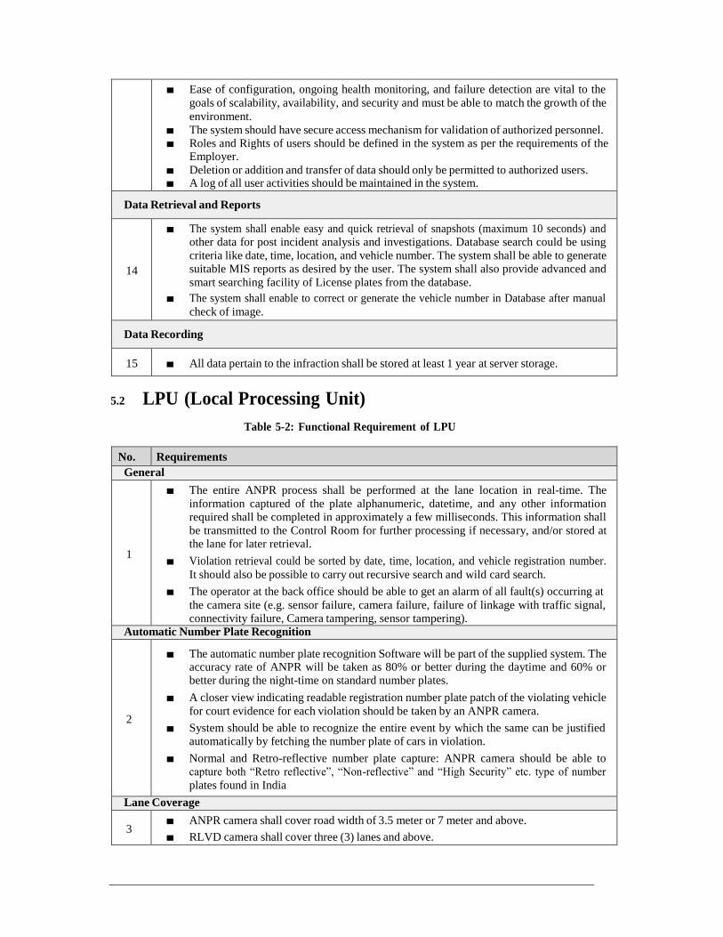
■ Ease of configuration, ongoing health monitoring, and failure detection are vital to the
goals of scalability, availability, and security and must be able to match the growth of the
environment.
■ The system should have secure access mechanism for validation of authorized personnel. ■ Roles and Rights of users should be defined in the system as per the requirements of the
Employer.
■ Deletion or addition and transfer of data should only be permitted to authorized users. ■ A log of all user activities should be maintained in the system.
Data Retrieval and Reports
14
■ The system shall enable easy and quick retrieval of snapshots (maximum 10 seconds) and other data for post incident analysis and investigations. Database search could be using
criteria like date, time, location, and vehicle number. The system shall be able to generate suitable MIS reports as desired by the user. The system shall also provide advanced and
smart searching facility of License plates from the database.
■ The system shall enable to correct or generate the vehicle number in Database after manual
check of image.
Data Recording
15 ■ All data pertain to the infraction shall be stored at least 1 year at server storage.
5.2 LPU (Local Processing Unit)
Table 5-2: Functional Requirement of LPU
No. Requirements
General
1
■ The entire ANPR process shall be performed at the lane location in real-time. The
information captured of the plate alphanumeric, datetime, and any other information required shall be completed in approximately a few milliseconds. This information shall
be transmitted to the Control Room for further processing if necessary, and/or stored at the lane for later retrieval.
■ Violation retrieval could be sorted by date, time, location, and vehicle registration number.
It should also be possible to carry out recursive search and wild card search.
■ The operator at the back office should be able to get an alarm of all fault(s) occurring at
the camera site (e.g. sensor failure, camera failure, failure of linkage with traffic signal, connectivity failure, Camera tampering, sensor tampering).
Automatic Number Plate Recognition
2
■ The automatic number plate recognition Software will be part of the supplied system. The accuracy rate of ANPR will be taken as 80% or better during the daytime and 60% or better during the night-time on standard number plates.
■ A closer view indicating readable registration number plate patch of the violating vehicle
for court evidence for each violation should be taken by an ANPR camera.
■ System should be able to recognize the entire event by which the same can be justified automatically by fetching the number plate of cars in violation.
■ Normal and Retro-reflective number plate capture: ANPR camera should be able to capture both “Retro reflective”, “Non-reflective” and “High Security” etc. type of number
plates found in India
Lane Coverage
3 ■ ANPR camera shall cover road width of 3.5 meter or 7 meter and above.
■ RLVD camera shall cover three (3) lanes and above.

Detection Speed
4
■ ANPR/RLVD cameras deployed should use fast electronic shutter (low exposure time)
should be used to capture even vehicles moving at 100 km/h without any image blur. Frame rate should be sufficient to capture all violations and all vehicle ANPR video.
Vehicle violation criterion at Intersection
5
The system shall detect and capture vehicle details when:
■ violates the stop line/zebra crossing
■ violates the red-light signal
System Mounting
6
■ System can be composite unit with all components inside the IP66 box or comprised of
camera or other units mounted on poles or gantries with controller and processors at side poles to make sure all lanes of the road are covered.
IR Illuminator
7
■ Integrated external Infrared shall be capable to take images in nighttime and automatically
detect number plate at distance of minimum 30 meters. The IR should be integrated with
camera unit with single power source
Security
8 ■ Standard Digital signature on each violation to assure data integrity. Strong encryption on
data during local storage and data transfer to back office / Cloud storage.
Data Storage at site
9
■ The output of the OCR process and all captured images shall be stored on an industrial
processing unit in the cabinet and also transmit to CCC.
■ If the connectivity to CCC is not established, then all data pertain to the infraction shall be stored at least 7 days on site and will be transferred once the connectivity is re-
established automatically. If when the data storage reaches capacity, the image processor shall automatically over-write the oldest data.
10
■ ALL vehicle ANPR capture system: The ANPR systems should also be capable of
capturing number plate and images of all vehicles passing through the installed
location. All vehicle images and numbers should be transmitted to control room and
kept in database for post search for analysis purposes.
Alert Generation
11
■ System shall be able to show live health status of each field component, subcomponents in control center and system shall be able to generate alert and display in the control room for
following status but not limited:
a. Power status (Law power, UPS),
b. Low battery alert,
c. Cabinet door Open, Close
d. Connectivity status
e. Illuminator Status f. Temperature status
g. Camera status
h. LPU alert etc.
Traffic Violation Detection
12
■ Minimum following “RLVD Analytics” shall be part of the RLVD System. The Incident to be detected by the RLVD System shall be” Stop Line Violation”, “Red Light Violation”, “Automatic Number Plate Recognition”,
■ The following addon functionality shall be cover in the proposed solution but not limited to “No Helmet”, “Triple Riding”.” Wrong Way”, “Hot Listed”, “Blacklisted”, “Stolen vehicle” etc.

■ The system shall have the function to enter manually for an offense based on evidence
collected by the RLVD system for further processing
■ Images zoom function for number plate and images should be provided. In case the
number plate of the infracting vehicle is readable only through the magnifier then in such
cases, the printing should be possible along with the magnified image. ■ The system shall be able to detect all vehicles infracting simultaneously in each lane/ arm
at the junction as per locations provided. It should also be able to detect the vehicles infracting serially one after another in the same lane. The vehicles should be identifiable and demarcated in the image produced by the camera system.
■ The Evidence image produced by the system should be wide enough to give the exact position of the infracting vehicles concerning the stop line and indicate the color of the Traffic light at the instant of Infraction even if any other means are being used to report the color of the light.
■ Some exceptional cases will be considered for non-detection of “RLVD Analytics” such
as.
a. The number plate detection could not process due to overlapping of another vehicle, b. Over speeding vehicle,
c. Non-Standard Number plate.
d. Number plate cover by Mud or non-readable form necked eye’s
e. Red Light Non-Functional or Malfunction but system shall have the functionality to track and update any such kind of alert on priority to authority and operator to register an incident.
f. Any other case study observed during operation shall be considered by the Employer /Consultant/Authorities shall be considered in the non-detection exemption.
General
13 ■ Entire functionalities define under this section shall be executed only at the LPU level and
shall not be an effect due to communication interruption with Server
6 Hardware Requirement
All hardware equipment shall as a minimum, meet all the requirements listed in the specifications. The equipment’s provided shall accommodate to future technological advances which exceeds the minimum requirements provided in the specifications.
6.1 RLVD Camera (Overview Camera)
Table 6-1: Hardware Requirement of RLVD Camera (Overview Camera)
No. Item Specification
1. Resolution 2MP or better, Minimum 1920 x 1080
2. Image Sensor Minimum 1/3” CCD/CMOS or better
3. Framerate min. 25/30 fps
4. Shutter Speed Auto/Manual: 1/50 to 1/10000 and above
5. Lens 3-12.7 mm or better (required )
6. Streams Minimum 3 simultaneous H.264 and MJPEG streams
7. Day night operation Automatic removable IR cut filter
8. Power 12 VDC or PoE IEEE 802.3af Class 1
9
Certification
The camera should be IP66 standards capable of withstanding
vandalism and harsh weather conditions (certification to be
produced) or better and Complete camera unit should have CE
certificate and test certifications.

Certification for box camera UL (Underwriters Laboratories) and BIS (Bureau of Indian Standards)
6.2 ANPR Camera
Table 6-2: Hardware Requirement of ANPR Camera
No. Item Specification
1 Video Compression H.264, H.265 or better
2 Video Resolution 2 MP or better
3 Frame rate Min. 25 FPS
4 Image Sensor 1/ 2.8” Progressive Scan CCD / CMOS
5 Lens Type Varifocal, C/CS Mount, IR Correction full HD lens
6 Shutter Speed 1/50 – 1/10,000 (25fps / 1 input)
7 Lens 5~50mm or suitable lenses to capture minimum 3.5 meters lane width from a minimum height of 6.5 meters or better
8 IR Cut Filter Automatically Removable IR-cut filter
9 Day/Night Mode Color, Mono, Auto
10 Region of Interest 4 zones (ON/OFF)
11 S/N Ratio ≥ 50 Db
12 WDR 120 dB
13 Stream H.264, H.265 / H.265+ Triple & Individual Configurable, At least 1 stream at 2MP @ 25 FPS, Minimum 3 simultaneous
14 Streaming Method Unicast, Multicast
15 Auto adjustment + Remote Control of
Image settings
Colour, Brightness, sharpness, contrast, white balance, exposure control, backlight compensation, Gain Control, Ture
Wide Dynamic Range
16 Local storage Minimum 128 GB Memory card in a Memory card slot. In the event of failure of connectivity to the central server the camera
shall record video locally on the SD card automatically to
storage video at 2MP, 25 fps for minimum 7 days. After the connectivity is restored, these recordings shall be
automatically merged with the server recording such that no manual intervention is required to transfer the SD card-based recordings to server. The SD storage shall be expandable up to 1TB.
17 Protocol IPv4, IGMP, ICMP, ARP, TCP, UDP, DHCP, PPPoE, RTP, RTSP, RTCP, DNS, DDNS, NTP, FTP, UPnP, HTTP, HTTPS, SMTP, 802.1x, SNMP, QoS
18 Security Password Protection, IP Address filtering, User Access Log, HTTPS Encryption
19 Operating conditions As per city weather conditions
20 Casing NEMA 4X / NEMA TS2 / IP-66 / IK10 rated
21 Alarm I/O Minimum 2 Input &1 / 2 Output contact for 3rd party integration
22 Video Interface 1 port (BNC) / Ethernet 1Vp-p, 75 Ohm
23 Certification UL, EN, CE, FCC, BIS
24 ONVIF Compliance The camera should be ONVIF Profile S & G Conformant for both present & future generation cameras of OEM

6.3 LPU (Local Processing Unit)
Table 6-3: Hardware Requirement of LPU
No. Item Specification
1. CPU Industrial or better
2. Memory 2 GB DDR2/DDR3 RAM better
3. Storage minimum 1 TB SSD
4. Network Adapter (NIC). 100 / 1000 base-t
5. Others The processor should be fanless type rated upto 70°
6.4 Network Infrastructure
The Contractor shall supply and install network equipment with necessary accessories at each
location to connect each peripheral to the system. The Bidder shall supply and install all equipment, cables, connectors, terminals and other miscellaneous materials necessary to establish a working local area network connecting these systems.
The type and the number of the network equipment proposed by the Bidder as per the network
design shall be mentioned by the Bidder in the BOQ. The network configuration shall be determined by the Bidder. The cost of the network devices and materials that is not explicitly listed in the BOQ of the Bid submitted by the Bidder or supplied by the Bidder during the installation works but deemed necessary for the system during any stage of this Contract shall be included in the cost of appropriate items and the Contract Price, and no separate payment shall be made.
6.5 Industrial Grade Layer -2 Switch
Table 6-4: Hardware requirement of Industrial grade Layer-2 switch
No. Item Requirements
1 Ethernet Interfaces 4 x 10/100/1000 Base-T PoE+ Ports auto-negotiation Plus 4 x 1000 Base-X SFP Uplink Slots (Should be loaded with 2 x 1G Single
mode Industrial Grade Fiber Modules supports up to 10 Km)
2 Performance Switching fabric 16 Gbps or more
Forwarding rate 11.8 Mpps or more
3 PoE Budget 120 Watts
4 VLANS 512
5 Level 2 switching IEEE 802.1, 802.3 standards, NTP, UDLD, LLDP, Unicast MAC filter, LACP, Private VLAN, Voice VLAN, VLAN double tagging (QinQ), STP, RSTP, MSTP, GARP, GMRP, GVRP, SNMPv1/v2c/v3, SNMP Inform, DHCP Server/Relay/Client, DHCP Option 66/67/82, BootP, RARP, TFTP, RMON, HTTP, HTTPS,
Syslog, MRP (Client), LLDP, 802.1x, NetFlow/sFlow, port
mirroring, Digital Diagnostic Monitoring (DDM)
6 Quality of Service (QoS)
Rate limit, auto QoS, ingress policing, egress queuing, and shaping
7 Multicast IGMPv1, v2, v3 snooping, IGMP filtering, IGMP querier, MLD snooping v1, v2

8 Management ICMP, Telnet, SSH, ARP, Syslog, SNMPv1/v2, RMON, SMTP, HTTP, HTTPS IPv4, IPv6

9 Security Port security, 802.1x, Dynamic VLAN assignment, Dynamic Host Configuration Protocol (DHCP) snooping, dynamic ARP inspection, IP Source Guard, storm control - unicast, multicast, broadcast, SSH, SNMPv3, TACACS+
10 Power Input Voltage 12 to 56 VDC with Redundant dual power inputs with 5-PIN Lockable Terminal Block
Reverse Polarity Protection
11 Warranty Min 5 years
12 Power Supply Bidder should provide Industrial Grade AC/DC DIN RAIL power supply.
6.6 SFP Transceiver
Table 6-5: Hardware requirement of SFP transceiver
No Item Requirements
1 Media Type Single-Mode or compatible with operator’s network to be surveyed by bidder
2 Data Rate 1250 (Mbps)
3 Grade Industrial
6.7 Din Rail Power Supply
Table 6-6: Hardware requirement of Din rail power supply
No Item Requirements
1 Input Voltage 180~240VAC
2 Input Frequency 50~60Hz
3 Output DC Voltage 48VDC±10%
4 Rated Current 2.5Amp
5 Current Range 0 ~ 5Amp
6 Rated Power 120W
7 Voltage Range 48~53VDC
8 Over-Voltage Protection 55~60VDC
9 Mounting Style DIN Rail
10 Warranty 2 Years
11 Grade Industrial
6.8 Gantry (U-Type)
Table 6-7: Hardware Requirement of Gantry (U-Type)
No. Item Specification
1. ■ The Contractor shall conduct the detailed design for the suitable gantry based on his/her site survey.
■ The minimum vertical clearance between the finished road surface and the bottom of the
support structure/bottom of the Gantry shall be 6 m. ■ Required Informatory/guide sign as per IRC67 shall be mounted.

■ The structure for mounting of RLVD equipment and informatory/guide sign should be designed for wind speeds as per IS-875 part 3.
■ The mounting should be capable of withstanding roadside vibrations at site of installation.
6.9 Cantilever (L-Type)
Table 6-8: Hardware Requirement of Cantilever (L-Type)
No. Item Specification
1. ■ The Contractor shall conduct the detailed design for the suitable cantilever based on his/her site survey.
■ The minimum vertical clearance between the finished road surface and the bottom of the
support structure/bottom of the cantilever shall be 6 m.
■ Required Informatory/guide sign as per IRC67 shall be mounted. ■ The structure for mounting of RLVD equipment and informatory/guide sign should be
designed for wind speeds as per IS-875 part 3. ■ The mounting should be capable of withstanding roadside vibrations at site of installation.
6.10 Power Supply and Outdoor UPS
Power supply and UPS shall be provided at each RLVD location. The Bidder shall present the calculation of power consumption and capacity of power supply system to be used for the RLVD system. The Bidder shall also consider the power requirement of network devices, wireless access points, switch, etc. suitably during the calculation. Proper earthing shall be provided at each equipment location.
The type and the number of the Power supply, Electric Meter proposed by the Bidder as per
the design shall be mentioned by the Bidder in the BOQ. The cost of the Power Supply devices and materials that is not explicitly listed in the BOQ of the Bid submitted by the Bidder or supplied by the Bidder during the installation works but deemed necessary for the system during any stage of this Contract shall be included in the cost of appropriate items and the Contract Price, and no separate payment shall be made.
Table 6-9: Hardware Requirement of UPS
No. Item Requirements
1. Input / Output Voltage
■ AC 230 V / 50 Hz basically. ■ Output voltage: AC230V/50Hz ■ Commercial Power generally but with existing condition of
power failure, instantaneous power failure and voltage fluctuation

2 UPS ■ The UPS shall be of True online with double conversion topology.
■ The UPS shall work in outdoor environment to ensure all
equipment’s getting necessary power supply. No power surge.
■ The UPS unit shall have load level indicators that display the approximate electrical load placed upon the UPS. The UPS unit shall have a row of battery level indicators that display the approximate battery capacity.
■ The UPS unit shall have a minimum of the following as per
OEM standard indicators:
➢ UPS Mode: On-line, Backup/Battery and Bypass; ➢ Over Load Indicator: This will display when UPS is
running on overload;

➢ Battery Status Indicator: This will illuminate when battery is low or faulty/disconnected; and
➢ System Fault: This will illuminate when there is some
fault or interruption in UPS.
■ The UPS unit shall include Ethernet communication port to support remote management and monitoring capabilities
using SNMP including alarm contacts and remote shutdown.
Remote monitoring and testing software shall be included. The manufacturer shall provide all SNMP traps.
■ The UPS unit shall include automatic restart. Upon
restoration of utility AC power after complete battery discharge, the UPS shall automatically restart and resume
operation. ■ The UPS unit shall be compliant to IEC 62040-1, CE,
IEC602040-2 safety standards. ■ The UPS and batteries shall be mounted in a separate cabinet
& the enclosure shall be under lock & key, utilising the minimum possible space and arranged in an aesthetic manner.
■ Any field UPS system (as per MSI’s design) shall be supplied
with an environmentally rated cabinet for installation of the UPS and batteries. The cabinet shall have a rating of IP 55.
The cabinet shall be supplied with in-built fans and proper
ventilation as needed to ensure that the temperature inside the cabinet does not exceed 40 degrees C at any given point in
time. ■ Backup time at least 3 hrs or more
6.11 Cabinet
Table 6-10: Hardware Requirement of
Cabinet
No. Item Specification
1. The cabinet shall be electrically and mechanically robust and shall have a degree of protection of IP65 or higher specified in “IEC60529 Degrees of Protection Provided by
Enclosures (IP Code)”.
The cabinet shall have the provision for temperature controlling for optimal performance of equipment.
A right hinged door shall be provided on the front to realize easy maintenance work. The turning direction of the handle shall be counterclockwise.
The power supply including UPS shall be provided with a circuit breaker.
The anti-lightning and surge protection complying with the IEC61643-1 shall be provided.
Protection under/overvoltage condition shall be provided.
Monitoring status of temperature, buttery and power supply
The cabinet shall be finished with the anticorrosive treatment
An internal lighting system
220VAC plugs protected by a differential circuit breaker
An intercom jack
A file holder for the documentation
Standard key locks
Fixed on metallic cabinet frames (when false floor)
7 Communication Requirement

Table 7-1: Communication Requirements of
RLVD
No. Requirements
1. ■ Communication between the roadside equipment of RLVD and the RLVD server at
Chennai Traffic Information and Management Centre shall be wired connectivity
provided by a single communication company, if required MPLS VPN shall be provided. ■ The required bandwidth for RLVD to ensure the stable communication connectivity shall be
proposed by the Contractor and subsequently approved by the Engineer.
8 Installation Requirement
The Contractor shall make the provision for necessary civil, foundation, earthing, necessary cable conducting, manhole, Power supply, redundant communication, new meter connection, quality, safety and last mile connectivity etc. to meet the functional requirement intended for the system. The Contractor shall obtain necessary permission from respective agency.
The Contractor shall make the provision of all types of necessary Road Marking to fulfill the SLA requirement during the project period. For greater efficiency of the RLVD system the necessary road marking ( such as stop line, etc) shall be done on a regular interval of at least every six months or more as required.
The RLVD solution is installed on the gantry or cantilever structure at the intersection depending on the applicability of the solution. While all the RLVD cameras, ANPR cameras are placed downstream of the stop-line/Before stop line monitoring it from behind for better performance to match define SLA.
All the ANPR cameras and RLVD cameras shall be mounted on the gantry / cantilever with the required informatory and other signages board as per applicable standards and as indicted in the reference drawing. In any case, RLVD cameras shall be placed at a height of approximately 6 m. ANPR cameras shall be placed at a height of 6 m as well overlooking the traffic approach shall be enforced .

Chapter 2-8 Requirements of Automatic Traffic
Counters-cum-classifier
1 General
The ATCC system includes two different types of Automatic Traffic Counter-cum-classifier
(ATCC), i.e., ATCC- 1 and ATCC-2.
The primary purpose of ATCC-1 is to collect speed data for vehicles on Chennai Bypass and Outer Ring Road where the Operational frequency of MTC buses is minimal. Data collected by the system will be used to supplement the Probe System to calculate the congestion level on these roads. ATCC-1 will be installed on both directions of Chennai Bypass and Outer Ring Road at the identified locations. The ATCC-1 also collect traffic volume data categorized into different classes of vehicle on ORR & Chennai Bypass.
The primary purpose of ATCC-2 is to collect traffic volume data categorized into different classes of vehicles, on arterial roads all over Chennai City. The collected data will be
accumulated and analyzed for road and traffic management purposes. They will be installed at mid-point locations between major junctions as well as collect speed of vehicles to provide information Probe System to calculate the congestion level on these roads.
The number of ATCC locations to be installed is:
ATCC-1: 86 units (on Chennai Bypass and Outer Ring Road at certain
intervals) ATCC-2: 144 units (at mid-point locations between major junctions
of arterial roads)
This is recommended as to be part of the implementation of this project (115 locations & 230
Numbers). This specification covers Automatic Traffic Counter-cum-Classifier (ATCC) system to be installed as one of the sub-systems of the Traffic Information System (TIS). The ATCC System shall be introduced to the Project with following objectives.
(a) To understand the current traffic condition through the traffic volume and vehicle speed data at the predetermined locations within the city and including some designated locations on Inner Ring
Road (IRR), Chennai Bypass Road, Outer Ring Road and National Highways.
(b) To accumulate traffic condition data useful for traffic management and road planning (c) To measure large-sized vehicle traffic for planning of future pavement repair or other road facility
maintenance
(d) To share the measured and processed traffic information with road planning agencies, road administrators and traffic police for their use
2 System Configuration
The ATCC System shall consist of the following components:
ATCC Server in the DC:
ATCC roadside equipment consisting of image recognition type detector, processing unit,
network equipment, power supply equipment and peripheral, Communication network between the ATCC Server and roadside equipment, and Supporting structure and foundation at site.
ATCC device installed in the project can be either a combined type or a separate type. The

combined type is the one where the image recognition detector and processing unit are supplied together as a single unit. The separate type is the one where the image recognition detector and
processing unit are installed as separate components. The interface between the image recognition detectors and processing unit shall be compatible each other in whatever the ATCC device type is installed in the project. No periodical manual adjustment shall be required for image recognition detector and processing unit.

The TIMS Command Control Centre shall have an ATCC Server for receiving pre-processed data from the ATCC roadside equipment. IP based network equipment shall be provided to connect the ATCC roadside equipment with the ATCC Server through wireless network or Fiber connectivity for better performance.
Cloud-based Datacentre
Figure 2-1: System Configuration of ATCC
3 Equipment Location and Type
The proposed locations for Automatic Traffic Counter and Classifier (ATCC) is shown below in the Table. The Contractor shall adhere to the proposed locations as much as possible to satisfy the above requirements. In case of any changes in the locations the Contractor shall get the written approval from the Engineer based on the alignment, geometry, viewing area (based on site visit).
Table 3-1: Target Locations of ATCC
No. ATCC ID Device ID Latitude Longitude Location Description
1 ATCC 1 ATCC 1-1 13.1371201 79.9148150 NH 716 ,SI Nagar,Thiruvallur 2 ATCC 2 ATCC 1-2
3 ATCC 3 ATCC 2-1 13.1265539 80.0123525 Church, Veppambaattu 4 ATCC 4 ATCC 2-2
5 ATCC 5 ATCC 3-1 13.1186349 80.0887953 NH 716 ,Gandhi Nagar, Avadi 6 ATCC 6 ATCC 3-2
7 ATCC 7 ATCC 4-1 13.1300571 80.1253971 Vaishnavi Nagar,Thirumullaivoyal 8 ATCC 8 ATCC 4-2
9 ATCC 9 ATCC 5-1 13.0999400 80.1684800 NH 205 ,Sai nagar ,Ambattur ,Industrial Estate 10 ATCC 10 ATCC 5-2
11 ATCC 11 ATCC 6-1 13.0900900 80.2288200 Palaiyam Nagar, Ayanavaram 12 ATCC 12 ATCC 6-2
13 ATCC 13 ATCC 7-1 12.9631718 79.9469125 NH 48, Nenmeli, Sriperumbudur 14 ATCC 14 ATCC 7-2
15 ATCC 15 ATCC 8-1 13.0247250 80.0241995 Madras Bombay Trunk Rd, Kuthambakkam 16 ATCC 16 ATCC 8-2
Roadside Equipment of ATCC Powered by Grid
Cabinet
Image Recognition Processing
Detector (LHS) Unit (LHS)
Network
Equipment
Image Recognition Processing
Detector (RHS) Unit(RHS)
Distribution Board
UPS
Power Supply (Grid)
Co
mm
un
ica
t

17 ATCC 17 ATCC 9-1 13.0556418 80.0934580 Poonamallee Bypass Rd, Poonamallee 18 ATCC 18 ATCC 9-2

No. ATCC ID Device ID Latitude Longitude Location Description
19 ATCC 19 ATCC 10-1 13.0652344 80.1729256 Ponamallee High Road, Pallavan
Nagar, Maduravoyal 20 ATCC 20 ATCC 10-2
21 ATCC 21 ATCC 11-1 13.0750943 80.2167051 Ponamallee High Road, NSK Nagar, Arumbakkam 22 ATCC 22 ATCC 11-2
23 ATCC 23 ATCC 12-1 13.0792000 80.2570800 Ponamallee High Road, Purasaiwakkam 24 ATCC 24 ATCC 12-2
25 ATCC 25 ATCC 13-1 12.7840712 80.0135220 Karaivanar Street, Thellar Big St, Peramanur , Maraimalai Nagar 26 ATCC 26 ATCC 13-2
27 ATCC 27 ATCC 14-1 12.8517094 80.0659531 Guduvanchery EB Office, Guduvanchery 28 ATCC 28 ATCC 14-2
29 ATCC 29 ATCC 15-1 12.9045602 80.0943644 Rajamanickam St, Balaji Nagar,
Tambaram East, New Perungalathur
30 ATCC 30 ATCC 15-2
31 ATCC 31 ATCC 16-1 12.9389500 80.1294900 Kamaraj Nagar Tambaram Sanatorium 32 ATCC 32 ATCC 16-2
33 ATCC 33 ATCC 17-1 12.9980900 80.1916900 Grand Southern Trunk Rd 34 ATCC 34 ATCC 17-2
35 ATCC 35 ATCC 18-1 13.0170000 80.2250000 Anna Salai Road ,Saidapet Bridge 36 ATCC 36 ATCC 18-2
37 ATCC 37 ATCC 19-1 13.3384581 80.1433989 Chennai Kolkata Hwy, Puduvoyal 38 ATCC 38 ATCC 19-2
39 ATCC 39 ATCC 20-1 13.2809000 80.1496900 SSS Complex, Panchetty NH-16 40 ATCC 40 ATCC 20-2
41 ATCC 41 ATCC 21-1 13.1697100 80.1997700 46, GNT Rd, Kavankarai, Puzhal 42 ATCC 42 ATCC 21-2
43 ATCC 43 ATCC 22-1 13.1499013 80.2129539 Chennai Kolkata Hwy, Retteri lake, Madhavaram 44 ATCC 44 ATCC 22-2
45 ATCC 45 ATCC 23-1 13.1323200 80.2368500 Old Madhavaram Bus Depot, Mcetich Colony, Madhavaram 46 ATCC 46 ATCC 23-2
47 ATCC 47 ATCC 24-1 13.2520407 80.2926704 Athipattu Main Rd, Athipattu Pudunagarr 48 ATCC 48 ATCC 24-2
49 ATCC 49 ATCC 25-1 13.2154759 80.2721526 SH 104, 50 ATCC 50 ATCC 25-2
51 ATCC 51 ATCC 26-1 13.1704165 80.3111301 SH 114, Jeevarathinam Nagar, Tiruvottiyur 52 ATCC 52 ATCC 26-2
53 ATCC 53 ATCC 27-1 13.1601361 80.2705482 Chennai Petroleum Corporation Limited Manali 54 ATCC 54 ATCC 27-2
55 ATCC 55 ATCC 28-1 13.1285812 80.2955441 Fishing Harbour ,Tondiarpet 56 ATCC 56 ATCC 28-2
57 ATCC 57 ATCC 29-1 13.0812593 80.2884150 Secretariat, Chennai Port Trust , Fort St George 58 ATCC 58 ATCC 29-2
59 ATCC 59 ATCC 30-1 13.0673200 80.2090100 72 A, Jawaharlal Nehru Rd, Vadapalani 60 ATCC 60 ATCC 30-2
61 ATCC 61 ATCC 31-1 13.0909400 80.1985800 Pioneer Colony, Anna Nagar West Extension 62 ATCC 62 ATCC 31-2
63 ATCC 63 ATCC 32-1 13.1274300 80.2091500 200 Feet Rd, Kannagi Nagar, Kolathur 64 ATCC 64 ATCC 32-2
65 ATCC 65 ATCC 33-1 13.1676784 80.2297548 Inner Ring Rd, Assisi Nagar, Madhavaram, Mathur 66 ATCC 66 ATCC 33-2
67 ATCC 67 ATCC 34-1 13.0619200 80.2829500 Kamarajar Promenade 68 ATCC 68 ATCC 34-2
69 ATCC 69 ATCC 35-1 13.0225500 80.2718300 Dinakaran Salai 70 ATCC 70 ATCC 35-2
71 ATCC 71 ATCC 36-1 12.9927300 80.2560500

No. ATCC ID Device ID Latitude Longitude Location Description
72 ATCC 72 ATCC 36-2 Indira Nagar, Adyar,
Thiruvanmiyur 73 ATCC 73 ATCC 37-1 12.9361300 80.2523500 ECR 74 ATCC 74 ATCC 37-2
75 ATCC 75 ATCC 38-1 12.8562100 80.2416200 Kanathur Reddykuppam 76 ATCC 76 ATCC 38-2
77 ATCC 77 ATCC 39-1 12.7821500 80.2294400 Kelambakkam 78 ATCC 78 ATCC 39-2
79 ATCC 79 ATCC 40-1 12.8550000 80.2260000 Semmancherry 80 ATCC 80 ATCC 40-2
81 ATCC 81 ATCC 41-1 12.8011400 80.1958200 Vandalur- Kelambakkam Road , Pudupakkam 82 ATCC 82 ATCC 41-2
83 ATCC 83 ATCC 42-1 12.8840127 80.1712996 MDR 633 Sithalapakkam 84 ATCC 84 ATCC 42-2
85 ATCC 85 ATCC 43-1 12.8594012 80.1322835 Kelambakkam-Vandalur Rd, Rathinamangalam 86 ATCC 86 ATCC 43-2
87 ATCC 87 ATCC 44-1 12.9001500 80.2345300 Ramaniyam Pushkar Phase 1, Kakaignar Karunanidhi Slai, Sholinganallur
88 ATCC 88 ATCC 44-2
89 ATCC 89 ATCC 45-1 12.9252900 80.2308200 Vivekananda Nagar, Karappakam 90 ATCC 90 ATCC 45-2
91 ATCC 91 ATCC 46-1 12.9061400 80.2062900 Medavakkam, Kailash nagar 92 ATCC 92 ATCC 46-2
93 ATCC 93 ATCC 47-1 12.9369300 80.2046900 Velachery-Tambaram Main Rd, Pallikaranai 94 ATCC 94 ATCC 47-2
95 ATCC 95 ATCC 48-1 12.9189325 80.1745277 Velachery Main Rd, Santhosapuram Vengavasal 96 ATCC 96 ATCC 48-2
97 ATCC 97 ATCC 49-1 12.9620000 80.2460000 Old Mahabalipuram Rd 98 ATCC 98 ATCC 49-2
99 ATCC 99 ATCC 50-1 12.9497203 80.2269481 SH109, Pallikaranai , Pallikaranai 100 ATCC 100 ATCC 50-2
101 ATCC 101 ATCC 51-1 12.9610600 80.2149300 Velachery Rd 102 ATCC 102 ATCC 51-2
103 ATCC 103 ATCC 52-1 12.9500000 80.1800000 Pallavaram-Thuraipakkam Rd 104 ATCC 104 ATCC 52-2
105 ATCC 105 ATCC 53-1 12.9724797 80.1390113 Pammal Main Rd, Krishna Nagar, Muthamizh Nagar, Pammal 106 ATCC 106 ATCC 53-2
107 ATCC 107 ATCC 54-1 13.0247528 80.1088646 Jaya Nagar, Mangadu 108 ATCC 108 ATCC 54-2
109 ATCC 109 ATCC 55-1 12.9813400 80.2417900 Mahatma Gandhi Nagar, Taramani Link Road 110 ATCC 110 ATCC 55-2
111 ATCC 111 ATCC 56-1 12.9975400 80.2164700 Velachery Main Rd 112 ATCC 112 ATCC 56-2
113 ATCC 113 ATCC 57-1 13.0080000 80.2340000 Sardar Patel Rd 114 ATCC 114 ATCC 57-2
115 ATCC 115 ATCC 58-1 13.0173400 80.1884800 Mount Poonamallee high Road 116 ATCC 116 ATCC 58-2
117 ATCC 117 ATCC 59-1 13.0393600 80.1320900 Mount Poonamallee high Road, Kattupakkam 118 ATCC 118 ATCC 59-2
119 ATCC 119 ATCC 60-1 13.0483614 80.1078896 Mount Poonamallee Road , Ayyappanthangal ,
Karayanchavadi 120 ATCC 120 ATCC 60-2
121 ATCC 121 ATCC 61-1 13.0447600 80.2630500 Dr.Radha Krishnan Salai, Kattukoil Garden,Mylapore 122 ATCC 122 ATCC 61-2

No. ATCC ID Device ID Latitude Longitude Location Description
123 ATCC 123 ATCC 62-1 13.0623400 80.2449700 Thousand Lights West 124 ATCC 124 ATCC 62-2
125 ATCC 125 ATCC 63-1 13.0538700 80.2266000 Arcot Road, United India Colony, Kodambakkam 126 ATCC 126 ATCC 63-2
127 ATCC 127 ATCC 64-1 13.1640553 80.0991952 MDR575, Bharathi Nagar, New Vellanyr 128 ATCC 128 ATCC 64-2
129 ATCC 129 ATCC 65-1 12.9766100 80.0506000 Kundrathur-Sriprembudur 130 ATCC 130 ATCC 65-2
131 ATCC 131 ATCC 66-1 12.9239700 80.0145900 Manimanglam Road SH 110 132 ATCC 132 ATCC 66-2
133 ATCC 133 ATCC 67-1 12.8556000 80.1995400 Karanai Main Road 134 ATCC 134 ATCC 67-2
135 ATCC 135 ATCC 68-1 13.0546400 80.2540500 Nagapattinam Chennai Hwy Road- Mount Road 136 ATCC 136 ATCC 68-2
137 ATCC 137 ATCC 69-1 13.0358400 80.2122800 Grand Southern Tunk Road 138 ATCC 138 ATCC 69-2
139 ATCC 139 ATCC 70-1 13.0620900 80.2364400 Tank Bund Road 140 ATCC 140 ATCC 70-2
141 ATCC 141 ATCC 71-1 13.0271000 80.2568100 2nd Main Road 142 ATCC 142 ATCC 71-2
143 ATCC 143 ATCC 72-1 13.0460700 80.1880400 Arcot Road 144 ATCC 144 ATCC 72-2
145 ATCC 145 ATCC 73-1 12.9182118 80.1013776 NH32-Chennai By-Pass 146 ATCC 146 ATCC 73-2
147 ATCC 147 ATCC 74-1 12.9568900 80.1194700 NH32-Chennai By-Pass 148 ATCC 148 ATCC 74-2
149 ATCC 149 ATCC 75-1 12.9961000 80.1229500 NH32-Chennai By-Pass 150 ATCC 150 ATCC 75-2
151 ATCC 151 ATCC 76-1 13.0464681 80.1497506 NH32-Chennai By-Pass 152 ATCC 152 ATCC 76-2
153 ATCC 153 ATCC 77-1 13.0571939 80.1597472 NH32-Chennai By-Pass 154 ATCC 154 ATCC 77-2
155 ATCC 155 ATCC 78-1 13.0736171 80.1610064 NH32-Chennai By-Pass 156 ATCC 156 ATCC 78-2
157 ATCC 157 ATCC 79-1 13.0921998 80.1614585 NH32-Chennai By-Pass 158 ATCC 158 ATCC 79-2
159 ATCC 159 ATCC 80-1 13.1098626 80.1636040 NH32-Chennai By-Pass 160 ATCC 160 ATCC 80-2
161 ATCC 161 ATCC 81-1 13.1267243 80.1684746 NH32-Chennai By-Pass 162 ATCC 162 ATCC 81-2
163 ATCC 163 ATCC 82-1 13.1375592 80.1845840 NH32-Chennai By-Pass 164 ATCC 164 ATCC 82-2
165 ATCC 165 ATCC 83-1 13.1458256 80.1963684 NH32-Chennai By-Pass 166 ATCC 166 ATCC 83-2
167 ATCC 167 ATCC 84-1 12.8830500 80.0813700 Chennai Outer Ring Road 168 ATCC 168 ATCC 84-2
169 ATCC 169 ATCC 85-1 12.8971100 80.0703000 Chennai Outer Ring Road 170 ATCC 170 ATCC 85-2
171 ATCC 171 ATCC 86-1 12.9166900 80.0753200 Chennai Outer Ring Road 172 ATCC 172 ATCC 86-2
173 ATCC 173 ATCC 87-1 12.9344300 80.0814200 Chennai Outer Ring Road 174 ATCC 174 ATCC 87-2
175 ATCC 175 ATCC 88-1 12.9513400 80.0877500 Chennai Outer Ring Road 176 ATCC 176 ATCC 88-2

No. ATCC ID Device ID Latitude Longitude Location Description
177 ATCC 177 ATCC 89-1 12.9694900 80.0897800 Chennai Outer Ring Road 178 ATCC 178 ATCC 89-2
179 ATCC 179 ATCC 90-1 12.9877100 80.0891000 Chennai Outer Ring Road 180 ATCC 180 ATCC 90-2
181 ATCC 181 ATCC 91-1 13.0032400 80.0894100 Chennai Outer Ring Road 182 ATCC 182 ATCC 91-2
183 ATCC 183 ATCC 92-1 13.0202200 80.0937100 Chennai Outer Ring Road 184 ATCC 184 ATCC 92-2
185 ATCC 185 ATCC 93-1 13.0383700 80.0870200 Chennai Outer Ring Road 186 ATCC 186 ATCC 93-2
187 ATCC 187 ATCC 94-1 13.0549400 80.0811400 Chennai Outer Ring Road 188 ATCC 188 ATCC 94-2
189 ATCC 189 ATCC 95-1 13.0704900 80.0711000 Chennai Outer Ring Road 190 ATCC 190 ATCC 95-2
191 ATCC 191 ATCC 96-1 13.0824100 80.0631300 Chennai Outer Ring Road 192 ATCC 192 ATCC 96-2
193 ATCC 193 ATCC 97-1 13.0965500 80.0521600 Chennai Outer Ring Road 194 ATCC 194 ATCC 97-2
195 ATCC 195 ATCC 98-1 13.1133900 80.0519200 Chennai Outer Ring Road 196 ATCC 196 ATCC 98-2
197 ATCC 197 ATCC 99-1 13.1319500 80.0526000 Chennai Outer Ring Road 198 ATCC 198 ATCC 99-2
199 ATCC 199 ATCC 100-1 13.1512700 80.0548800 Chennai Outer Ring Road 200 ATCC 200 ATCC 100-2
201 ATCC 201 ATCC 101-1 13.1655400 80.0657600 Chennai Outer Ring Road 202 ATCC 202 ATCC 101-2
203 ATCC 203 ATCC 102-1 13.1765400 80.0791400 Chennai Outer Ring Road 204 ATCC 204 ATCC 102-2
205 ATCC 205 ATCC 103-1 13.1790800 80.0976600 Chennai Outer Ring Road 206 ATCC 206 ATCC 103-2
207 ATCC 207 ATCC 104-1 13.1816800 80.1158600 Chennai Outer Ring Road 208 ATCC 208 ATCC 104-2
209 ATCC 209 ATCC 105-1 13.1790600 80.1342700 Chennai Outer Ring Road 210 ATCC 210 ATCC 105-2
211 ATCC 211 ATCC 106-1 13.1870100 80.1492800 Chennai Outer Ring Road 212 ATCC 212 ATCC 106-2
213 ATCC 213 ATCC 107-1 13.2020600 80.1595100 Chennai Outer Ring Road 214 ATCC 214 ATCC 107-2
215 ATCC 215 ATCC 108-1 13.2155800 80.1760300 Chennai Outer Ring Road 216 ATCC 216 ATCC 108-2
217 ATCC 217 ATCC 109-1 13.2201100 80.1867000 Chennai Outer Ring Road 218 ATCC 218 ATCC 109-2
219 ATCC 219 ATCC 110-1 13.2291100 80.2038900 Chennai Outer Ring Road 220 ATCC 220 ATCC 110-2
221 ATCC 221 ATCC 111-1 13.2393300 80.2194300 Chennai Outer Ring Road 222 ATCC 222 ATCC 111-2
223 ATCC 223 ATCC 112-1 13.2516000 80.2351800 Chennai Outer Ring Road 224 ATCC 224 ATCC 112-2
225 ATCC 225 ATCC 113-1 13.2648700 80.2469900 Chennai Outer Ring Road 226 ATCC 226 ATCC 113-2
227 ATCC 227 ATCC 114-1 13.2695000 80.2618200 Chennai Outer Ring Road 228 ATCC 228 ATCC 114-2
229 ATCC 229 ATCC 115-1 13.2791600 80.2601700 Chennai Outer Ring Road to Minjur 230 ATCC 230 ATCC 115-2

4 System Functional Requirement
The ATCC-1 and ATCC-2 hall have the functionalities described below.
Table 4-1: Functional Requirement of ATCC
Application
No. Requirements
Vehicle Detection and Counting Function
1. The ATCC roadside equipment shall continuously take the image of the road area covered. It shall be possible to adjust the angle and coverage area of the image recognition detector to maximize the
detection accuracy. Images taken by the ATCC equipment shall be processed to obtain the required traffic data. The processing unit shall be capable of:
■ Detecting all types of vehicle including auto rickshaw moving in any direction and recognize the shape or edge of the vehicle.
■ Counting the number of vehicles that pass the sensing area during the unit measurement time. ■ For ATCC-1, classifying the vehicle into large and small size vehicle shall be required. The
definition of the large and small size shall be made according to the vehicle length and the
classification parameter shall be adjustable. ■ For ATCC-2, classifying the vehicle into Truck, Bus, Sedan, Subcompact Car and Auto-
Rickshaw as a minimum classification shall be required. The definition of the large and small size shall be made according to the vehicle length and the classification parameter shall be adjustable.
■ Calculating an average speed per unit time which is the arithmetic average of the speed of vehicles that have passed the sensing area during one-unit measurement time.
■ The ATCC system is expected to have 92% for vehicle counting accuracy and 85% for vehicle classification accuracy. Contractor shall propose the counting accuracy to be
guaranteed.
■ Unit duration of detection, measurement and calculation shall be one (1) minute time interval.
Data Processing Function
2. The ATCC roadside equipment shall process the vehicle detection data and produce the following
data:
■ One-minute traffic volume ■ One minute large-sized vehicle volume ■ One-minute arithmetic average speed
Data Transmission Function
3. The ATCC roadside equipment shall send the processed data to the ATCC Server in TIMS
Command Control Centre along with the equipment status at one-minute interval. The data
transmission timing shall use the internal timer of the roadside equipment.
Sub-system Types of Data Interval
ATCC System
Traffic volume (all types)
One (1) minute
Traffic volume (large)
Average speed
Equipment operational status
Error Checking Function

4. The data sent from the roadside equipment shall be tested first for possible errors. The thresholds shall be defined, and data received from the roadside equipment shall be checked
with the threshold. If a data is judged as abnormal, the equipment shall be marked as marginal. If marginal data continues consecutively for the specified number of times, the equipment shall be
marked as malfunctioned. Likewise, if error signal is sent from ATCC roadside equipment, it shall be marked malfunctioned, and an alarm shall be issued to the Operator Console. The

faulty detector shall be recorded in the operation log. The data judged as abnormal shall not be used for further processing.
The data from the vehicle detector marked as malfunctioned shall be checked continuously for data abnormality. If data is judged normal, normal processing of the data shall resume
automatically.
Data Processing Function
5. The ATCC Server shall process the one-minute traffic data collected into five (5) minute data.
Traffic volume shall be the sum of the latest five one-minute data and speed data shall be the
arithmetic average of the latest five one-minute data.
Five-minute traffic volume data shall be accumulated into one-hour traffic volume data and
one-hour data shall be accumulated into 24-hour traffic volume data. No further processing is
required for the average speed data longer than five-minute data.
Data storage and retrieval function
6 All processed data shall be stored in the ATCC server and then TIMS Server for analysis and future usage. In addition, status of ATCC roadside equipment (normal or malfunctioned) shall
be recorded in the ATCC Server as operation log with error code and time stamp for future reliability analysis. Data retrieval and presentation software shall be provided to show the
historical traffic flow data and operating condition of the specified roadside equipment location
at the specified time, hour or day. Graphical presentation of historical traffic flow data such as hourly variation and daily variation shall also be considered.
The processed traffic volume information is aggregated for 1 hour, day, month and saved for a certain period (over 1 year) file. Data older than the retention period shall be deleted in order
from the oldest and old data can be saved in the storage device etc. of the TIMS Server. In
addition to the above data, it also stores information necessary for system operation. It is assumed that the saved information can be output (MS Excel etc.) from the operator console.
Sub-System Data Interval/Timing
ATCC System
Traffic volume (all types) 5 minutes / 1hour/ 24 hours
Traffic volume (large) 5 minutes / 1hour/ 24 hours
Average speed 5 minutes
Equipment status Upon status change
Screen Display Function
7 The information display shall be schematic map-based interface and as well in the form of a
list. The schematic map-based display shall cover the entire selected area and be able to enlarge
individual locations on the map when selected. The enlarged view shall be able to display the details for each selected location. The details displayed shall cover not be limited, the contents described in the Table below.
Item Contents on Schematic Map Graphic List
Equipment location and status
Location of ATCC roadside equipment and
its status (normal / malfunctioned)
Current traffic volume
One (1) minute volume (all/large) One (1) minute average speed
Five (5) minute volume (all type/large) Five (5) minute average speed
Historical traffic volume
Five (5) minute volume (all type/large) variation
Five (5) minute speed variation Hourly traffic volume variation (all type /large)

Health Status & Alert
Door Open, close, Power status on UPS or Row, subcomponents health status etc.
Operation log Error log (date and time of failure and recovery)
Parameter Parameters for viewing and editing
Reporting Function
8 The ATCC Server shall have the reporting function as described hereunder. The reports shall be generated as per the schedule or upon the system operator’s request. It shall be possible to generate the report as a file in portable document file format.
Item Contents
Traffic volume Daily report of hourly traffic volume (all type and large vehicle) Monthly report of daily traffic volume by vehicle class (all type and large vehicle)
Operation and error log
Status (normal / malfunctioned) of roadside equipment Error record (showing date and time of failure and recovery)
Alert Function
9 ■ System shall be able to show live health status of each field component, sup components in
control center and system shall be able to generate alert and display in the control room for following status but not limited:
a. Power status (Law power, UPS),
b. Low battery alert,
c. Cabinet door Open, Close d. Connectivity status e. Temperature status f. Image processing unit status g. LPU alert etc.
Data Storage at site
■ The analyzed data of ATCC at the site shall be stored on an industrial processing unit in the
cabinet and also transmit to CCC. ■ If the connectivity to CCC is not established, then all data pertain to the infraction shall be
stored at least 7 days on site and will be transferred once the connectivity is re-established
automatically. If when the data storage reaches capacity, the image processor shall automatically over-write the oldest data.
Others
9 ■ The ATCC System shall measure the traffic flow data listed below at the locations specified. The unit duration of measurement, detection, identification and calculation shall
be within one (1) minute interval.
✓ Volume of all types of vehicle (Truck, BUS, Sedan, Subcompact Car, Auto-
Rickshaw etc.)
✓ Vehicle Speed ■ The system shall process the data measured and the measurement location. ■ The ATCC System shall produce sufficiently accurate traffic condition data even under
complex traffic and road conditions in and around Chennai. ■ The traffic data shall be transmitted to the TIMS Command Control Centre at specified
interval and the data shall be stored for a certain period.
■ Image recognition type ATCC equipment shall be adopted, and it shall detect vehicles on multiple lanes of traffic.
■ The detection target of ATCC shall be vehicles passing through the sensor area at a speed not less than 1 km/h and not more than 160 km/h.
■ The ATCC system is expected to have 92% for vehicle counting accuracy and 85% for
vehicle classification accuracy.
■ The Contractor shall state the accuracy of ATCC that he proposes together with supporting
data in his technical proposal.

■ The ATCC system shall be share required data with other ITS components as well as Servers.
■ The ATCC system shall maintain the communication log/acknowledgment for data
exchange with other systems.
■ All the maintenance, SLA, Inventory, fault related activity for ATCC system shall be automated, manageable, trackable through CCC.
■ The Contractor shall demonstrate the accuracy proposed in his technical proposal under the
test conditions defined by the Engineer during technical evaluation
■ The following vehicles and conditions shall be excluded for measurement
✓ Vehicles running in the opposite direction
✓ Hidden vehicles due to overlapping with the vehicles in front.
5 Hardware Requirement
All hardware equipment shall as a minimum, meet all the requirements listed in the
specifications. The equipment’s provided shall accommodate to future technological advances
which exceeds the minimum requirements provided in the specifications.
5.1 Image Recognition Detector and Processing Unit
Table 5-1: Hardware Requirement of Image Recognition Detector and Processing Unit
No. Item Specifications
1. Imaging device CCD or MOS or CMOS
2. Effective pixels 640(H) x 480(V) or more
3. Resolution VGA: 640 x 480 or more
4. Image distribution MPEG-4 / H.264, JPEG
5. Frame rate 25 fps or more
6. Detected data ■ Traffic volume (Large vehicle/Small vehicle) ■ Vehicle Speed
7. Transmitting Period 1 Minutes
8. LAN Interface 10BASE-T/100BASE-TX (RJ-45) x 1 port
9. Power Requirements AC220-240V, 50Hz Backup power supply: UPS with 15 minutes backup
10 Power Consumption 100 VA or less
11 Operating Temperature 0 to +70 degrees Celsius
12 Degrees of Protection Image Recognition Detector: IP67 or more
13 Lightning-induced surge protection
IEC 61643-1 Class Ⅱ or better
14 Reliability and maintainability
MTBF: 30,000 hours MTTR: 0.5 hours
5.2 LPU(Local Processing Unit)
Table 5-2: Hardware requirement of Local Processing Unit
No. Item Specification
1. CPU Industrial or better
2. Memory 2 GB DDR2/DDR3 RAM better

No. Item Specification
3. Storage minimum 1 TB SSD
4. Network Adapter (NIC). 100 / 1000 base-t
5. Others The processor should be fanless type rated upto 70°
5.3 Network Infrastructure
The Contractor shall supply and install network equipment at each location to connect each
peripheral to the system. The Bidder shall supply and install all equipment, cables, connectors, terminals and other miscellaneous materials necessary to establish a working local area network connecting these systems. The network between the Control Centre and sub-systems shall either use the optical fibre cable network or high-end Wireless Access Points along the Project Area and a data communication network shall be established using layered switches to be supplied by the Contractor.
The type and the number of the network equipment proposed by the Bidder as per the network design shall be mentioned by the Bidder in the BOQ. The network configuration shall be determined by the Bidder. The cost of the network devices and materials that is not explicitly listed in the BOQ of the Bid submitted by the Bidder or supplied by the Bidder during the installation works but deemed necessary for the system during any stage of this Contract shall be included in the cost of appropriate items and the Contract Price, and no separate payment shall be made.
5.4 Industrial Grade Layer -2 Switch
Table 5-3: Hardware requirement of Industrial grade Layer-2 switch
No. Item Requirements
1 Ethernet Interfaces 4 x 10/100/1000 Base-T PoE+ Ports auto-negotiation Plus 4 x 1000
Base-X SFP Uplink Slots (Should be loaded with 2 x 1G Single mode Industrial Grade Fiber Modules supports up to 10 Km)
2 Performance Switching fabric 16 Gbps or more
Forwarding rate 11.8 Mpps or more
3 PoE Budget 120 Watts
4 VLANS 512
5 Level 2 switching IEEE 802.1, 802.3 standards, NTP, UDLD, LLDP, Unicast MAC
filter, LACP, Private VLAN, Voice VLAN, VLAN double tagging (QinQ), STP, RSTP, MSTP, GARP, GMRP, GVRP,
SNMPv1/v2c/v3, SNMP Inform, DHCP Server/Relay/Client, DHCP Option 66/67/82, BootP, RARP, TFTP, RMON, HTTP, HTTPS,
Syslog, MRP (Client), LLDP, 802.1x, NetFlow/sFlow, port mirroring, Digital Diagnostic Monitoring (DDM)
6 Quality of Service (QoS)
Rate limit, auto QoS, ingress policing, egress queuing, and shaping
7 Multicast IGMPv1, v2, v3 snooping, IGMP filtering, IGMP querier, MLD snooping v1, v2
8 Management ICMP, Telnet, SSH, ARP, Syslog, SNMPv1/v2, RMON, SMTP, HTTP, HTTPS IPv4, IPv6
9 Security Port security, 802.1x, Dynamic VLAN assignment, Dynamic Host
Configuration Protocol (DHCP) snooping, dynamic ARP inspection, IP Source Guard, storm control - unicast, multicast, broadcast, SSH, SNMPv3, TACACS+

10 Power Input Voltage 12 to 56 VDC with Redundant dual power inputs with 5-PIN Lockable Terminal Block

No. Item Requirements
Reverse Polarity Protection
11 Warranty Min 5 years
12 Power Supply Bidder should provide Industrial Grade AC/DC DIN RAIL power supply.
5.5 SFP Transceiver
Table 5-4: Hardware requirement of SFP transceiver
No Item Requirements
1 Media Type Single-Mode or compatible with operator’s network to be surveyed by bidder
2 Data Rate 1250 (Mbps)
3 Grade Industrial
5.6 Din Rail Power Supply
Table 5-5: Hardware requirement of Din rail power supply
No Item Requirements
1 Input Voltage 180~240VAC
2 Input Frequency 50~60Hz
3 Output DC Voltage 48VDC±10%
4 Rated Current 2.5Amp
5 Current Range 0 ~ 5Amp
6 Rated Power 120W
7 Voltage Range 48~53VDC
8 Over-Voltage Protection 55~60VDC
9 Mounting Style DIN Rail
10 Warranty 2 Years
11 Grade Industrial
5.7 Power Supply and Outdoor UPS
Power supply and UPS shall be provided at each ATCC location. The Bidder shall present the
calculation of power consumption and capacity of power supply system to be used for the ATCC. The Bidder shall also consider the power requirement of network devices, wireless access points, switch, etc. suitably during the calculation. Proper earthing shall be provided at each equipment location.
The type and the number of the Power supply, Electric Meter proposed by the Bidder as per
the design shall be mentioned by the Bidder in the BOQ. The cost of the Power Supply devices and materials that is not explicitly listed in the BOQ of the Bid submitted by the Bidder or supplied by the Bidder during the installation works but deemed necessary for the system during any stage of this Contract shall be included in the cost of appropriate items and the Contract Price, and no separate payment shall be made.

Table 5-6: Hardware Requirement of Outdoor UPS
No. Item Requirements

1. Input / Output Voltage
■ AC 230 V / 50 Hz basically. ■ Output voltage: AC230V/50Hz ■ Commercial Power generally but with existing condition of power failure,
instantaneous power failure and voltage fluctuation
2 UPS ■ The UPS shall be of True online with double conversion topology. ■ The UPS shall work in outdoor environment to ensure all equipment’s
getting necessary power supply. No power surge.
■ The UPS unit shall have load level indicators that display the approximate electrical load placed upon the UPS. The UPS unit shall
have a row of battery level indicators that display the approximate battery capacity.
■ The UPS unit shall have a minimum of the following as per OEM standard indicators:
➢ UPS Mode: On-line, Backup/Battery and Bypass; ➢ Over Load Indicator: This will display when UPS is running on
overload; ➢ Battery Status Indicator: This will illuminate when battery is low or
faulty/disconnected; and
➢ System Fault: This will illuminate when there is some fault or interruption in UPS.
■ The UPS unit shall include Ethernet communication port to support remote management and monitoring capabilities using SNMP including
alarm contacts and remote shutdown. Remote monitoring and testing
software shall be included. The manufacturer shall provide all SNMP traps.
■ The UPS unit shall include automatic restart. Upon restoration of utility
AC power after complete battery discharge, the UPS shall automatically restart and resume operation.
■ The UPS unit shall be compliant to IEC 62040-1, CE, IEC602040-2 safety standards.
■ The UPS and batteries shall be mounted in a separate cabinet & the enclosure shall be under lock & key, utilising the minimum possible
space and arranged in an aesthetic manner. ■ Any field UPS system (as per MSI’s design) shall be supplied with an
environmentally rated cabinet for installation of the UPS and batteries. The
cabinet shall have a rating of IP 55. The cabinet shall be supplied with in- built fans and proper ventilation as needed to ensure that the temperature
inside the cabinet does not exceed 40 degrees C at any given point in time.
■ Backup time at least 3 hrs or more
5.8 Cabinet
Table 5-7: Hardware Requirement of
Cabinet
No. Item Specification
1. ■ The cabinet shall be electrically and mechanically robust and shall have a degree of
protection of IP65 or higher specified in “IEC60529 Degrees of Protection Provided by Enclosures (IP Code)”.
■ The cabinet shall have the provision for temperature controlling for optimal performance of equipment.
■ A right hinged door shall be provided on the front to realize easy maintenance work. The turning direction of the handle shall be counterclockwise.
■ The power supply including UPS shall be provided with a circuit breaker.
■ The anti-lightning and surge protection complying with the IEC61643-1 shall be
provided.

■ Protection under/overvoltage condition shall be provided. ■ Monitoring status of temperature, buttery and power supply
■ The cabinet shall be finished with the anticorrosive treatment
■ An internal lighting system
■ 220VAC plugs protected by a differential circuit breaker ■ An intercom jack
■ A file holder for the documentation ■ Standard key locks ■ Fixed on metallic cabinet frames (when false floor)
5.9 Pole
Table 5-8: Hardware Requirement of Pole
No. Item Specification
1. ■ The Contractor shall conduct the detailed design for the pole based on his site survey. ■ The Contractor shall conduct the appropriate measure for preventing the vibration which
will affect the detection accuracy. ■ All components of poles may be hot dip galvanized, all components must be well
protected against corrosion, minimum thickness of zinc coatings is 85 µ m and min
density 500 gm/m 2 on both inside and outside surfaces ■ Certified BS EN 10025-4:2019 – TC ■ Required Lighting arrester arrangement inside the pole.
6 Communication Requirement
Table 6-1: Communication Requirements of
ATCC
No. Minimum Specifications
1. ■ Communication between the ATCC server in the CCC and the ATCC roadside
equipment shall be Wireless 3G/4G or upcoming 5G Connectivity provided by a single communication company.
■ The required bandwidth to make the system functional shall be proposed by the Contractor
7 Installation Requirement
The Contractor shall make the provision for necessary civil, foundation, earthing, necessary
cable conducting, manhole, Power supply, redundant communication, new meter connection, quality, safety and last mile connectivity etc. to meet the functional requirement intended for the system. The Contractor shall obtain necessary permission from respective agency.
ATCC-1 need to be installed on Chennai Bypass Road and Chennai Outer Ring road and
ATCC-2 need to be installed within the city on major link roads .
ATCC camera sensors need to be housed in a cabinet. Sensors should be placed in the median as far as possible. If possible, sensors covering both directions need to be installed in the median on a single pole to optimize installation, civil works, and maintenance cost. In case sensors are not feasible to be placed in the median, a practical roadside location should be chosen such that detectors can cover all the lanes in the direction under study and optimal detection can be achieved.

Poles, fixtures, and other peripherals should be manufactured in accordance with relevant standards and need to be secured on a foundation.

Chapter 3 Requirements of City Bus System
Chapter 3-1 Requirements of Command Control Centre for City Bus System
1 General
The City Bus System (CBS) shall be an integrated system that supports effective operation of the MTC fleet and accurate real-time information to riders about the status of operations:
The CBS-CCC is intended to achieve the overall objectives as described below.
(a) The Command Control Centre (CCC) must create an environment in which information is gathered,
processed, and disseminated clearly and in real time.
(b) Each bus shall be equipped with an On-Board Unit (OBU) for location tracking that incorporates
cellular data communications and sends frequent periodic location reports to the central operations management system at the CBS Command Control Centre.
(c) These periodic location reports will provide ongoing information about current traffic speed on key
road segments, to serve as traffic probes data input to other systems. (d) The Command Control Centre fleet operations management software will support the operation
and effective use of a Computer Aided Dispatch / Automatic Vehicle Location (CAD/AVL) system. This will enable tracking of the route and schedule adherence for each vehicle, and the
management/logging of incidents. (e) The Passenger Information System (PIS) will use the route and schedule adherence tracking
information to provide information about predicted arrival times on PIS at many terminals and bus shelters visible to waiting riders. And providing this real-time information through a website and mobile application.
(f) Each depot will be equipped with the Depot Management System (DMS) to enable and manage their effective operation. This software will manage service scheduling, crew rostering, vehicle
dispatch, crew attendance, and business intelligence/reporting.
(g) Provide information and data management system for the overall control, supervision,
configuration, and maintenance of Bus service.
(h) Real time monitoring of fleet on GIS map based on geo positions received from the onboard device
mounted on buses and simultaneous constant computation of expected arrival times at downstream
stations using the efficient travel time algorithms.
(i) Operational management and alert monitoring of the buses in real-time to ensure improved
efficiency for the agency and better service to the commuters
(j) Passive monitoring of safety and security for city service infrastructure and real-time decision
making for any emergency management services.
(k) Transmitting of all the outputs to the corresponding ITS units at stations or on-board of the buses
in real-time through wired / wireless communication system.
(l) Transfer necessary information to the concerned agencies like police, GCC and CUMTA
authorities.
(m) As it supports a lot of data processing and transmitting, CCC requires large amount of
communication system to support its operations through wired or wireless.
(n) The accurate data analysis includes the data cleaning, fusion and analysis. Once data from the
sensors or onboard device received to CCC, it should be checked. Reliable passenger information
should be passed on to the public on-time through efficient system having the capabilities to
transmit the information through SMS, Internet and to terminal.

Figure 1-1: Concept of CBS Functions

Internet
Server
2 System Configuration
MTC Command and Control Centre Video Wall (DLP, 70-inch x8x6)
L2-SW
Video Switcher
Video Switcher
(Console)
x 16 Operator Terminal
(3 Monitors)
Chennai Traffic Information
and Management Centre
L3-SW
x 20
Land line phone
(IP phone)
IP-PBX
Call Recording
Device
x 2 Network Color
Laser Printer
x 2
Firewall with
IPS
Internet
Router
L2-SW
Server Load
Balancer
Hypervisor
Hypervisor
Internet
Server x 2
Cen
tra
l Ma
na
ge
men
t Serv
er
(ma
in)
PIS
Serv
er (m
ain
)
CA
D/A
VL
Serv
er (m
ain
)
TID
S S
erv
er (m
ain
)
VM
S S
erv
er (m
ain
)
ITM
S S
erv
er (m
ain
)
System Server Architecture
on Cloud for Disaster Recovery
Figure 2-1: System Configuration of CBS Command Control Center
3 Equipment Location
Table 3-1: Location of CBS Command Control Center
No. Location Type Location Name
1 CBS Command Control Center MTC Corporate Office
4 System Functional Requirement
4.1 Server Architecture
The system server architecture for the System is shown in the figure below.
Storage (NAS)
SAN-SW
Netw
ork
pro
vid
ed b
y IS
P
Cen
tra
l Ma
na
gem
en
t
Serv
er (m
ain
)
Co
ntr
ol C
en
tre S
erv
er
(ma
in)
CA
D/A
VL
Server
(ma
in)
PIS
Serv
er (m
ain
)
Cen
tra
l Ma
na
ge
men
t
Serv
er (sta
nd
by
)
Co
ntr
ol C
en
tre S
erv
er
(stan
db
y)
CA
D/A
VL
Server
(stan
db
y)
PIS
Serv
er (sta
nd
by
)
DM
S S
erv
er (m
ain
) D
MS
Serv
er (sta
nd
by
)

System Server Architecture
at Chennai Traffic Information & Management Centre
System Server Architecture
at MTC Command & Control Centre
Figure 4-1: System Server Architecture the
System
4.2 Data Centre
The data center shall be used to house all active equipment like all Application, Database and
Domain server with primary and redundant capability, Security system, Network Switch, IP
communication equipment etc. in logical perspective, for CBS application, CAD/AVL, PIS
and DMS.
Data center of CBS-CCC shall be the heart and core of MTC to maintain important
information and serving communication between field equipment and central system
servers. All information held and processed by datacenter is subject to the risks of attack,
error and natural disaster, and other vulnerabilities inherent to its use. The up time of the
CITS Project systems shall be high and shall maintain security up to high level for data,
equipment etc. by the Contractor.
The Contractor shall maintain following standards for Data Center
■ TIA‐942: Telecommunications Infrastructure Standard for Data Centre - TIA‐942 defines
practical methods to ensure electrical continuity throughout the rack materials and proper
grounding of racks and rack‐ mounted equipment. This is the only specification that addresses
problems specific to data center infrastructure.
■ ISO 27001 – ISMS: The Data center should comply with ISO 27001 – ISMS guideline provided by International Organization for Standardization. This standard helps organizations
keep information assets of the Data center secure.
■ Guideline of MUHA and relevant update time to time
Data Storage for traffic big
data (physical only)
Data Storage for traffic big
data (physical only)
ITMS Server (Application
& Database) x2
ATCS Server (Application
& Database) x2
TIDS Server (Application
& Database) x2
VMS Server (Application &
Database) x2
RLVD Server (Application
& Database) x2
SLVD Server (Application
& Database) x2
PIS Server (Application &
Database) x2
DMS Server (Application &
Database) x2
(Application & Database) x2
Hypervisor Hypervisor
Replication of Hypervisor on Cloud
Traffic Information and Management System Component City Bus System Component
ITMS Server (Application
& Database) x1
TIDS Server (Application
& Database) x1
VMS Server (Application &
Database) x1
PIS Server (Application &
Database) x1

4.3 Disaster Recovery
Table 4-1: Functional requirement of Disaster recovery
No. Requirements
General
1
■ The Contractor shall propose the suitable disaster recovery plan for the System. ■ The minimum following two (2) servers of City Bus System which will be critical for
operation at a time of disaster shall be protected by replicating them on cloud.
(1) Computer Aided Dispatch/Automatic Vehicle Location Server (Application and Database) to continue the service to bus uses at a time of disaster.
(2) Passenger Information Server (Application and Database) to continue the service to bus users at a time of disaster
Replication Method
2.
■ The Contractor shall propose the suitable replication method for the System. ■ Host based replication will be preferable for the data replication. ■ The traffic big data
Recovery Time Objective (RTO) / Recovery Point Objective (RPO)
3. ■ Recovery Time Objective (RTO) shall be less than 24.0 hours ■ Recovery Point Objective (RPO) shall be less than 24.0 hours
4.4 Security
Table 4-2: Functional requirement of Security
No. Requirements
Security requirement
1. ■ For Control Center End point security is essential to any device that is physically an
end point on a network. Laptops, desktops, mobile phones, tablets, servers can all be termed as endpoints.
■ Endpoint security refers to cybersecurity services for network endpoints. These services
include antivirus, email filtering, web filtering, and firewall services. Endpoint security plays a crucial role for businesses, ensuring critical systems, intellectual property,
customer data, employees, and guests are protected from ransomware, phishing,
malware, and other cyberattacks. ■ Endpoint Service Features
✓ Anti-virus - Smart Scan leverages anti-malware and antispyware signatures stored
in-the-cloud ✓ Anti-spyware - Conventional Scan leverages anti-malware and antispyware
components stored locally on Security Agents ✓ Application Control (Win PC only) - Create rules to restrict the applications that
can execute or install on the endpoints.
✓ Behavior Monitoring Incl. Ransomware Protection (Win PC only) - Behavior
Monitoring protects endpoints from unauthorized changes to the operating system,
registry entries, other software, or files and folders. Protect documents against unauthorized encryption or modification, automatically back-up and restore files
changed by suspicious programs, Block processes commonly associated with ransomware, enable program inspection to detect and block compromised
executable files
■ Endpoint Sensor ■ Firewall (Win PC only) - The firewall can block or allow certain types of network traffic
by creating a barrier between the endpoint and the network
■ Full Disk Encryption ■ HTTPS Web Threat Protection

■ Predictive Machine Learning ■ Role-based Administration ■ Unauthorized Change Prevention Service (Win PCs only) - Regulates application
behavior and validates program trustworthiness. ■ URL Filtering - URL Filtering allows administrators to block specific types of websites
during different times of the day. ■ Industry leading protection from Virus, Spyware, Phishing and Hacking. URL filtering.
USB Port Blocking. Data Theft prevention
■ Web Reputation enhances protection against malicious websites. ■ Physical or virtual network appliance that monitors 360 degrees of network to create
complete visibility into all aspects of targeted attacks, advanced threats, and
ransomware. ■ Prevent assess potential vulnerabilities and proactively protect endpoints, servers, and
applications. Detect advanced malware, behavior, and communications invisible to standard defenses. Enable rapid response through shared threat intelligence and
delivery of real-time security updates. Must gain centralized visibility across the
network and systems; analyze and assess the impact of threats. ■ Ability to scan through all file types and various compression formats. Ability to scan
HTML, VBScript Viruses, malicious applets and ActiveX controls. Able to update itself
over internet for virus definitions, program updates etc. (periodically as well as in push- updates in case of outbreaks).
■ Able to perform different scan Actions based on the virus type (Trojan/ Worm, Joke, Hoax, Virus, other). Provides Real-time Product Performance Monitor, Built-in Debug
and Diagnostic tools, and context – sensitive help. The solution provides protection to
multiple remote clients. Provides for virus notification options for Virus Outbreak Alert and other configurable conditional Notification. Capable of providing multiple layers
of defense. Facility to clean, delete and quarantine files affected with virus. Supports online update, whereby most product updates and patches can be performed without bringing messaging server off-line.
CCTV surveillance at Control Centre
2 ■ The Contractor must supply, installation, commissioning, and maintenance of
appropriate CCTV system to monitor activity in CBS-CCC related for CITS Project Facilities such as server room, UPS Room, inventory Room etc
✓ Fixed Dome Camera ✓ Fixed Bullet Camera
✓ Fisheye Camera ✓ NVR With 42” Monitor ✓ Storage Capacity minimum 4 months ✓ 5 MP or better
4.5 Enterprise Management System
Table 4-3: Functional requirement of Enterprise Management System (EMS)
No. Requirements
ENTERPRISE MANAGEMENT SYSTEM (EMS)
Network Management and Control
1 ■ The network management function shall be provided to the system and the function shall
continuously monitor the Level 2 switch and Layer 3 switch using Simple Network
Management Protocol (SNMP). In case of identification of a malfunction, the network management system shall issue an alarm to the operator console and at the same time store the malfunction record in the network operation log.

No. Requirements
■ Database storage shall have a capacity of 2 years for recording the operation log.
■ SLA calculation and reporting function shall be provided.
■ The proposed system shall support multiple types of discovery like IP range discovery –
including built-in support for IPv6, Seed router-based discovery, and discovery whenever
new devices are added with the capability to exclude specific devices.
■ The proposed system shall support the exclusion of specific IP addresses or IP address
ranges.
■ The proposed solution shall provide a detailed asset report, organized by proper naming of
all devices, listing all ports for all devices. The proposed system shall provide sufficient
reports that identify unused ports in the managed network infrastructure that can be reclaimed and reallocated.
■ The proposed solution shall determine device availability and shall exclude outages from
the availability calculation with an option to indicate the reason.
■ The proposed solution shall provide the box root cause analysis.
■ The proposed solution shall have an integrated user-friendly application.
■ The proposed solution shall include all required licenses.
■ The proposed solution shall provide real-time monitoring of the entire network infrastructure and shall allow users to easily navigate with a graphical interface and easy- to-use network management tools.
■ The proposed solution shall provide at a minimum, event alert via the existing Microsoft Exchange Server email or pop-up alarm or export to CSV.
■ The proposed solution shall automatically generate reports on a daily, weekly, and monthly basis in formats including graphs, bar charts, distribution, and summary. The system shall
be capable of printing out reports and also exporting the reports to other systems or web servers.
■ The proposed solution shall display a simple map of the whole network as a tree and shall have the option of direct selection of objects. The system shall provide a navigation tree to
display the current alarm status of each subnet. All the systems shall support PAN/ ZOOM feature and shall have all the devices visible in one window along with the provision for
these two features
■ The proposed solution shall provide polling agents to upload status, changes, or alerts of
the local devices attached with the Ethernet enabling devices.
■ The proposed solution shall provide real-time Management Information Bases (MIBs)
displays and shall provide the MIB variable data in tabular or graphical format. The MIB
displays shall provide various expressions like utilization, percentage errors, and volume
■ The proposed solution shall provide features for security and accountability and shall
generate a log file for any user access to configuration or platform changes.
■ The proposed solution shall be capable of managing any SNMP/ICMP device from any vendor.
■ The proposed solution shall support SNMPV1, SNMPV2C, and SNMPV3 and shall automatically discover and poll SNMP and ICMP devices.
■ SNMP traps for all IP-enabled devices shall be provided by the respective product manufacturers.
■ The proposed solution shall allow notifications to be automatically sent to phones, offsite workstations, etc. for efficient response.
■ The proposed solution shall monitor as a minimum the base station unit and the subscriber station units along with other IP-enabled equipment that is being provided as part of this
Project.
■ The proposed solution shall allow for providing different levels of security access i.e.,
viewing, logging and managing.

No. Requirements
■ The proposed solution shall allow for the display of different colors for the links including
red, green, orange, yellow to show the status of the links and the connected devices
■ The operation of the NMS shall be tested while the backbone network is under 30% network utilization.
■ The proposed solution must provide an interface for IT helpdesk personnel to create guest credentials.
■ The proposed solution shall be supplied with a server with Windows or Linux-based OS (latest) or later.
Service Level - Monitoring, Management, and Reporting
2 ■ The proposed service management system shall provide a detailed service dashboard view
indicating the health of each of the components and services provisioned as well as the
SLAs
■ The system shall provide an outage summary that gives a high-level health indication for each service as well as the details and root cause of an outage.
■ The system shall be capable of managing IT and Non-IT resources in terms of the business services they support, specify and monitor service obligations, and associate users/Departments/ Organizations with the services they rely on and related Service/Operational Levels Agreements. Presently, services shall include E-mail, Internet Access, Intranet, and other services hosted.
■ SLA violation alarms shall be generated to notify whenever an agreement is violated or is in danger of being violated. These alarms shall be automatically shared with the authorized
people.
■ The system shall provide the capability to designate planned maintenance periods for services and take into consideration maintenance periods defined at the IT resources level.
In addition, the capability to exempt any service outage from impacting an SLA shall be available.
■ The reports supported shall include one that monitors service availability (including Mean
Time to Repair (MTTR), Mean Time Between Failure (MTBF), and Maximum Outage Time thresholds) and the other that monitors service transaction response time.
■ The system shall provide a historical reporting facility that shall allow for the generation
of on-demand and scheduled reports of Service-related metrics with capabilities for customization of the report presentation.
Application Performance - Monitoring, Management, and Reporting
3 ■ The proposed solution shall proactively monitor all user transactions for any web application hosted; detect failed transactions; gather evidence necessary for triage and diagnosis of problems that affect user experiences and prevent completion of critical business processes.
■ The proposed solution shall determine if the cause of performance issues is inside the
application, in connected back-end systems, or at the network layer.
■ The proposed solution shall correlate performance data from HTTP Servers (external
requests) with internal application performance data.
■ The proposed solution shall see response times based on different call parameters. For example, the proposed solution shall be able to provide CPU utilization metrics.
■ The proposed solution shall allow data to be seen only by those with a need to know and
limit access by user roles.
■ The solution shall be deployable as an appliance or physical or virtual server-based system acting as an active/passive listener on the network thus inducing zero overhead on the
network and application layer.

No. Requirements
■ The proposed solution shall be able to provide the ability to detect and alert which exact
end-users experience HTTP error codes such as 404 errors or errors coming from the web
application.
■ The proposed system shall be able to detect user-impacting defects and anomalies and
reports them in real-time for Slow Response Time, Fast Response time, Low Throughput, Partial Response, Missing component within the transaction.
■ The proposed system shall be able to instantly identify whether performance problems like
slow response times are within or outside the Datacenter without having to rely on network monitoring tools.
Systems and Database Performance - Monitoring, Management, and Reporting
4 ■ The proposed system shall address management challenges by providing centralized
management across physical and virtual systems.
■ The proposed system shall be able to monitor various operating system parameters such as
processors, memory, files, processes, file systems, etc. where applicable, using operators on the servers to be monitored.
■ It shall be possible to configure the operating system monitoring operators to monitor based
on user-defined thresholds for warning/critical states and escalate events to the event
console of the enterprise management system.
■ It shall also be able to monitor various operating system parameters depending on the
operating system being monitored yet offer a similar interface for viewing the operators
and setting thresholds.
■ The proposed solution shall support monitoring Processors, File Systems, Log Files,
System Processes, and Memory, etc.
■ The proposed tool shall provide Process and NT Service Monitoring wherein if critical application processes or services fail, administrators are immediately alerted, and processes
and services are automatically restarted.
■ The proposed tool shall be able to provide Log File Monitoring which enables the
administrator to watch system logs and text log files by specifying messages to watch for.
When matching messages get logged, the proposed tool shall notify administrators and enable them to take action like sending an email.
■ The proposed database performance management system shall integrate network, server & database performance management systems and provide a unified view of the performance
state in a single console.
■ It shall be able to automate monitoring, data collection, and analysis of performance from a single point.
■ It shall also provide the ability to set thresholds and send notifications when an event occurs, enabling Database Administrators (DBAs) to quickly trace and resolve
performance-related bottlenecks.
■ Role-based Access — Enables role-based management by defining access privileges according to the role of the user.
■ The proposed Virtual Performance Management system shall integrate the latest
virtualization technologies.
Helpdesk - Monitoring, Management, and Reporting
5 ■ The proposed helpdesk system shall provide flexibility of logging, viewing, updating, and
closing incident manually via the web interface.
■ The proposed helpdesk system shall support ITIL processes like request management, problem management, configuration management, and change order management with
out-of-the-box templates for various ITIL service support processes.
■ Each incident shall be able to associate multiple activity logs entries via a manual update

No. Requirements
or automatic update from other enterprise management tools.
■ The proposed helpdesk system shall be able to provide flexibility of incident assignment
based on the workload, category, location, etc.
■ Each escalation policy shall allow easy definition on multiple escalation levels and notification to different personnel via window GUI/console with no or minimal
programming.
■ The proposed helpdesk system shall provide grouping access to different security knowledge articles for different groups of users.
■ The proposed helpdesk system shall have an updatable knowledge base for technical
analysis and further help end-users to search for solutions for previously solved issues.
■ The proposed helpdesk system shall support tracking of SLA (Service Level Agreements)
for call requests within the help desk through service types.
■ The proposed helpdesk system shall be capable of assigning call requests to tech al staff manually as well as automatically based on predefined rules, and shall support notification and escalation over email, web, etc.
■ The proposed helpdesk system shall integrate tightly with the knowledge tools and CMDB and
shall be accessible from the same login window.
■ It shall allow the IT team to create solutions & make them available on the end-user login window for the most common requests.
■ The helpdesk shall be a web-enabled management system with an SMS and email-based alert system for the Helpdesk Call management and SLA reporting.
■ The Help desk shall log user calls related to the system and assign an incident/ call ID
number. Severity shall be assigned to each call as per the SLAs.
■ Helpdesk shall track each incident/call to resolution. Escalate the calls, to the appropriate
levels, if necessary, as per the escalation matrix agreed upon with Authority/authorized
entity.
Traffic Analysis through EMS
6 ■ The traffic analysis system shall be from the same OEM providing Network Fault &
Performance Management System.
■ The tool shall support Flow monitoring and traffic analysis for NetFlow, J-Flow, sFlow, Netstream, IPFIX technologies.
■ The solution shall provide a central web-based integration point across any of the flow
protocols and shall be able to report from a single console.
■ The solution shall be of passive-type and should not cause any performance overheads.
Incident Management and Root Cause Analysis Reporting
7 ■ An information security incident is an event (or chain of events) that compromises the confidentiality, integrity, or availability of information. All information security incidents
that affect the information or systems of the enterprise (including malicious attacks,
abuse/misuse of systems by staff, loss of power/communications services, and errors by users or computer staff) shall be dealt with following a documented information security
incident management policy
■ Incidents shall be categorized and prioritized. While prioritizing incidents the impact and urgency of the incident shall be taken into consideration.
■ It shall be ensured that the incident database is integrated with the Known Error Database (KeDB), Configuration Management Database (CMDB). These details shall be accessible
to relevant personnel as and when needed.
■ Testing shall be performed to ensure that recovery action is complete and that the service has been fully restored.

No. Requirements
■ When the incident has been resolved, it shall be ensured that the service desk records of the resolution steps are updated and confirm that the action taken has been agreed to by the
end-user. Also, unresolved incidents (known errors and workarounds) shall be recorded and reported to provide information for effective problem management.
■ Information security incidents and weaknesses associated with information systems shall
be communicated in a manner allowing timely corrective action to be taken
Change and Configuration Management
8 ■ Change management provides information on changes and enables better control of
changes to reduce errors and disruption in services.
■ All changes shall be initiated using a change management process, and a Request for Change (RFC) shall be created. All change requests shall be evaluated to determine the impact on business processes and IT services and to assess whether change shall adversely affect the operational environment and introduce unacceptable risk.
■ All changes are logged, prioritized, categorized, assessed, authorized, planned, and scheduled to track and report all changes. All the logs should be immutable.
■ Ensure review of changes for effectiveness and take actions agreed with interested parties. Change requests shall be analyzed at planned intervals to detect trends. The results and conclusions drawn from the analysis shall be recorded and reviewed to identify opportunities for improvement.
■ The roles and responsibilities of the management shall include review and approval of the implementation of change management policies, processes, and procedures
■ A configuration management database shall be established which stores unique information about each type of Configuration Item CI or group of CI.
■ The Configuration Management Database (CMDB) shall be managed such that it ensures its reliability and accuracy including control of update access.
■ The degree of control shall maintain the integrity of services and service components taking into consideration the service requirements and the risks associated with the CI.
■ Corrective actions shall be taken for any deficiencies identified in the audit and shall be reported to the management and process owners
■ Information from the CMDB shall be provided to the change management process and the changes to the CI shall be traceable and auditable.
■ A configuration baseline of the attached CI shall be taken before deployment of a release into the live environment. It shall be stored in a safe environment with appropriate access
control.
■ Master copies of CI shall be recorded in the CMDB and shall be stored in secure physical
or electronic libraries which shall be referenced in the configuration records. This shall
apply to documentations, license information, software, and hardware configuration images.
■ The NMS shall facilitate the retrieval, storage, analysis, and display of status information from all network devices attached to the system that are SNMP and/or ICMP capable and
shall facilitate remote configuration of these devices. NMS shall support both IPv4 and IPv6 device integration.
■ The NMS shall provide the ability to view the network and its associated IP SNMP/ICMP
enabled devices including switches and other IP devices connected over the network. It shall support a minimum of 10,000 endpoints
5 Hardware Requirement
All hardware equipment shall as a minimum, meet all the requirements listed in the specifications. The equipment’s provided shall accommodate to future technological advances which exceeds the minimum requirements provided in the specifications.

5.1 Servers
Table 5-1: Hardware requirement of Servers
No. Items Requirements
1 General ■ Minimum 6U size, rack-mountable, capable of accommodating
minimum 8 or higher hot-pluggable blades ■ Have the capability for installing industry-standard flavors of
Microsoft Windows, and Enterprise RedHat Linux OS as well as
virtualization solutions such as VMware. ■ DVD ROM shall be available in chassis, can be internal or external,
which can be shared by all the blades allowing remote installation of
software ■ Minimum 1 USB port
2 Processor ■ Latest series/ generation of 64-bit x86 processor(s) with Ten or
higher Cores
■ Processor speed should be a minimum of 2.4 GHz
■ Minimum 2 processors per physical server
3 RAM Min. 24 DIMM slots, should be provided with 256 GB RAM using DDR4
DIMM's operating at 2666 MT/s (depending on processor model)
4 Internal Storage 2 x 400 GB SAS (10k rpm) hot swap disk with extensible bays
5 Network interface 2 X 20GbE LAN ports for providing Ethernet connectivity
Optional: 1 X Dual-port 16Gbps FC HBA for providing FC connectivity
6 Power supply Dual Redundant Power Supply
7 RAID support As per requirement/solution
8 Operating System The licensed version of 64 bit latest version of Linux/ Unix/Microsoft®
Windows-based Operating system
9 Form Factor Rack mountable/ Blade
10 Virtualization Shall support Industry-standard virtualization hypervisors like Hyper-V,
VMWARE, and Citrix.
11 Storage controller SAS Raid Controller with RAID 0/1
12 Bus Slots Minimum of 2 Nos of PCIe 3.0 based mezzanine slots supporting
Converged Ethernet adapters
13 Motherboard Intel Chipset compatible with the offered processor
14 Interfaces Minimum of 1 Internal USB 3.0 port, 1 Internal SD Card Slot
15 Redundancy Must have port level and card level redundancy

No. Items Requirements
16 Operating System
& Virtualization
Support
■ Microsoft Windows Server (latest version)
■ Red Hat Enterprise Linux (RHEL) (latest version)
■ SUSE Linux Enterprise Server (latest version)
■ VMware / feature-rich virtualization software supporting solution
design & stack
17 Warranty 5 Year OEM Warranty
5.2 Video Wall
Table 5-2: Hardware requirement of Video wall
No. Item Requirements
1. Display Type Color DLP Laser or LED light source
2. Display Size 70 inches or higher - DLP Cube- With Laser Light Source or LED Light Source – SLIM Cube
3 Videowall Grid
Videowall in the matrix with 9 (3 cubes in column and 3 cubes in row)
4. Number of pixels
1920×1080 (full HD), 16:9 Widescreen
5. Contrast Ratio 1800:1 or higher
6. Brightness 700 nits
7. Bezel-to-Bezel Width
0.44 or Bezel less
8. Viewing angle 178 degree/178 degree (H/V)
9. Access to the Cube
Front/Rear access
10. Input Signal RGB Digital, DVI-D or HMDI (Input interface shall be compatible with output interface of Video Switches.)
11. Control input RS-232C(D-SUB9) or RJ-45(10/100BASE-T)
12. Expected Power Consumption
400VA or less
13. Mount VESA Standard Mount Interface
14. Control On Screen Display (OSD) - IP/IR remote control
15. Operations 24 x 7, Life of light source 100000 hrs in eco-mode.
16. Standards BIS or equivalent
5.3 Video Wall Controller
Table 5-3: Hardware requirement of Video wall controller
No Item Requirements
1. Controller Controller to control Video wall as per requirement along with software

2. Chassis 19” Rack mount
3. Processor Latest Generation 64-bit Quad Core processor (3.3Ghz) or better
4. Operating System Pre-loaded 64-bit Operating System Windows / Linux / Equivalent, with
recovery disc
5. RAM 16 GB DDR3 ECC RAM
6. HDD 2x500 GB 7200 RPM HDD
7. Networking Ethernet Controller with RJ-45 port
8. Power Supply (1+1) Redundant hot swappable
9. Accessories Keyboard and Optical USB mouse
10. USB Ports Minimum 4 USB Ports
11. Redundancy support Power Supply, HDD, LAN port & Controller
12. Scalability Display multiple source windows in any size, anywhere on the wall
13. Control functions Brightness/Contrast/ Saturation/ Hue/ Filtering/ Crop/ Rotate
14.
Inputs
Controller should also have at least
12 or 24 DVI/HDMI inputs for connecting workstations
15. Output To connect to required Displays through HDMI/DVI
16. Operating Temperature 10°C to 35°C, 80 % humidity
17. Cable & Connections The Contractor should provide all the necessary cables and connectors,
so as to connect Controller with Display units
18.
Integration
Seamless integration among display unit, controller, wall management
software to be ensured. Preferred to have same OEM.
5.4 Video Wall Management Software
Table 5-4: Requirement of Video wamm Management Software
No Items Requirements
1. Display &Scaling At least 20 layers
2. Input Management All input sources can be displayed on the video wall in freely
resizable and movable windows
3. Scenarios management Save and load desktop layouts from local or remote machines
4. Layout Management Support all layout from input sources, Internet Explorer, desktop
and remote desktop application
5. Multi View Option Multiple view of portions or regions of Desktop, multiple
application can view from single desktop
6.
Other features
SMTP support
7. Remote Control over LAN
8. Alarm management
9. Remote management
10. Multiple concurrent client

11. KVM support
5.5 LED Display
Table 5-5: Hardware requirement of LED display
No Item Requirements
1. Product Type LED-backlit LCD flat panel display with touchscreen
2. Diagonal Size 70”
3. Commercial Use Yes - interactive
4. Resolution 1920 x 1080
5. Display Format 1080p (Full HD)
6. Video Interface HDMI
7. HDMI Ports Qty 3 ports
8. PC Interface VGA (HD-15), DisplayPort, Mobile High-Definition Link (MHL)
9. LCD Backlight Technology LED backlight
10. Image Aspect Ratio 16:9
11. TV Tuner No tuner
12. Speaker System 2 speakers
13. USB Yes
14. Included Accessories Remote control, 2 styluses, stylus pen holder, wireless remote control, wire saddle, remote control holder, LSA1U wall mount kit
15. Voltage AC 120/230 V (50/60 Hz)
16. Power Consumption Operational
220 Watt
17. Power Consumption Stand by 0.4 Watt
18. Dimensions (WxDxH) 159.35 cm x 9.51 cm x 93.261 cm
19. Environmental Standards ENERGY STAR Qualified
5.6 Data Storage
Table 5-6: Hardware Requirement of Data Storage
No Item Requirements
1. Solution/ Type IP Based/iSCSI/FC/NFS/CIFS
2. Storage Storage Capacity should be a minimum of 50 TB (usable, after configuring
in offered RAID configuration) for online and Near-line data.
RAID solution offered must protect against double-disc failure.
Disks should be preferably minimum of 8 TB capacity
To store all types of data (Data, Voice, Images, Video, etc)
Storage system capable of scaling vertically and horizontally
3. Hardware Platform Rack-mounted form-factor
Modular design to support controllers and disk drives expansion
4. Controllers At least 2 Controllers in active/active mode
The controllers / Storage nodes should be upgradable seamlessly, without
any disruptions/downtime to production workflow for performance, capacity
enhancement, and software/firmware upgrades.
5. RAID support RAID 0, 1, 1+0, 5+0 and 6

No Item Requirements
6. Cache Minimum 128 GB of useable cache across all controllers. If the cache is
provided in additional hardware for a unified storage solution, then the cache
must be over and above 128 GB.
7. Redundancy and
High Availability
The Storage System should be able to protect the data against a single point
of failure concerning hard disks, connectivity interfaces, fans, and power
supplies
8. Management
software
All the necessary software (GUI Based) to configure and manage the storage
space, RAID configuration, logical drives allocation, snapshots, etc. are to be
provided for the entire system proposed.
Licenses for the storage management software should include disc
capacity/count of the complete solution and any additional disks to be
plugged in in the future, up to the max capacity of the existing
controller/units.
A single command console for the entire storage system.
Should also include storage performance monitoring and management
software
Should provide the functionality of proactive monitoring of Disk drive and
Storage system for all possible disk failures
Should be able to take "snapshots" of the stored data to another logical drive
for backup purposes
9. Data Protection The storage array must have a complete cache protection mechanism either
by de-staging data to disk or providing complete cache data protection with
battery backup for up to 4 hours
5.7 Backup Software
Table 5-7: Hardware requirement of Backup software
No Item Requirements
1 General ■ The software shall be able to back up the necessary and relevant video
feeds from storage, various databases, etc. The device should provide
minimum throughput of 10Gbps
■ Should support file-level backup/recovery.
■ Should perform Scheduled unattended backup using policy-based
management for all Server and OS platforms
■ The software should support online backup and restore of various
applications and Databases
■ Should support database platforms like Microsoft Exchange Server,
Oracle, Microsoft SQL Server, Microsoft SharePoint, Sybase, MySQL,
Informix, IBM Domino (Lotus), SAP, IBM DB2, Big database etc.
■ Should support backup hardware like tape, virtual tape, optical, disk,
interface hardware, etc
■ The backup software should be capable of having multiple back-ups
sessions simultaneously
■ The backup software should support different types of backup such as Full
back up, Incremental back up, Differential back up, Selective back up, Point
in Time back up, and Progressive Incremental back up and snapshots

■ The backup software should support different types of user interface
such as GUI, Web-based interface
Should have logging and reporting features
5.8 Tape Library
Table 5-8: Hardware requirement of Tape library
No. Requirements
1. ■ Shall support Native data capacity of 200TB ■ (uncompressed) expandable to 400TB (compressed).
2 ■ Shall be offered with Minimum of four LTO7 FC tape drive. Drive shall support encryption.
3 ■ Shall be offered with minimum of 48 Cartridge slots and scalable to minimum 100 Cartridge
4 ■ Tape Library shall provide 8 Gbps native FC connectivity to SAN switches.
5 ■ Library shall be able to back up the encrypted keys in a redundant fashion
6 ■ Tape Library shall provide web based remote management.
7 ■ The library should have cartridge I/O slots for secure & easy off‐site backup storage
8 ■ Tape Library shall have GUI Panel ■ Shall be rack mountable.
■ Shall have option for redundant power supply
9 ■ Should support industry leading backup software
10 ■ 40 LTO7 barcode labelled cartridges & 4 cleaning cartridges from the tape library OEM
to be provided
5.9 Network Switch -Level 2
Table 5-9: Hardware Requirement of Network Switch -Level 2
No. Item Requirements
1. Switching bus 56 Gbps or more Switching fabric capacity or better
2. WAN Interface 1) 10/100BASE-TX x4 port or more
2) Optical port (Media Converter) x2 port or more
3. LAN Interface 100/1000BASE-T x16 port or more and two SFP
4. LAN Protocol TCP/IP, IP Multicast
5. Level 2 switching function
Present
6. Maximum VLAN 200 or better
7.
VLAN Trunk function
Support 802.1Q Tagged VLAN and port-based VLANs and Private VLAN
The switch must support dynamic VLAN Registration or equivalent
Dynamic Trunking protocol or equivalent
Should support Media access control (MAC) authentication to provide simple authentication based on a user's MAC address
8. Spanning Tree Possible
9. Routing Protocol RIP, RIPv2, OSPF

Network Time Protocol or equivalent Simple Network Time
Protocol support.
The switch should support traffic segmentation.
Traffic classification should be based on user-definable
application types: TOS, DSCP, Port-based, TCP/UDP port
number
10. Multicast IGMP
11. Monitoring/control SNMPv1, v2, and v3 and Remote monitoring (RMON) support
12. Power AC230V
14 Grade Industrial
5.10 Network Switch -Level 3
Table 5-10: Hardware Requirement of Network Switch -Level 3
No. Item Requirements
1. Switching bus 56 Gbps or more Switching fabric capacity or better
2. WAN Interface 1) 10/100BASE-TX x4 port or more
2) Optical port (Media Converter) x2 port or more
3. LAN Interface 100/1000BASE-T x16 port or more and two SFP
4. LAN Protocol TCP/IP, IP Multicast
5. Layer 3 switching function
Present
6. Maximum VLAN 200 or better
7.
VLAN Trunk function
Support 802.1Q Tagged VLAN and port based VLANs and Private VLAN
The switch must support dynamic VLAN Registration or equivalent
Dynamic Trunking protocol or equivalent
8. Spanning Tree Possible
9.
Routing Protocol
RIP, RIPv2, OSPF Network Time Protocol or equivalent Simple Network Time Protocol support.
Switch should support traffic segmentation.
Traffic classification should be based on user-definable application types: TOS, DSCP, Port based, TCP/UDP port number
10. Multicast IGMP
11. Monitoring/control SNMP
12. Power AC230V
5.11 SAN Switch
Table 5-11: Hardware requirement of SAN switch
No. Item
Requirements

1. Converge Fiber switch should be quoted with a minimum of 48 FC ports of 16 Gbps
speed with all supported licenses from day one.
2. Protocols Fibre channel or Ethernet
3. Controllers The switch should have auto-sensing, zoning, integrate Ethernet, and a serial
port for communication
4. Chassis The switch should be rack-mountable 1U size and should be supplied with a
mounting kit
5. Redundancy The switch should be equipped with a redundant hot-swap power supply and
fan and allow hot-swap ability with resetting the switch or affecting the
operations of the switch
5.12 Load Balancer
Table 5-12: Hardware requirement of Load balancer
No Item Requirements
1
General
■ The device should support load balancing of both TCP and UDP based
traffic using algorithms like round-robin, weighted round-robin, least
connections, persistent connects, etc
■ The device should provide minimum throughput of 10Gbps
■ The device should provide 4x10G ports scalable to an additional
4x10G ports
■ Should support Client availability (Heartbeat) monitoring
■ Should support High Availability in Active-Active, Active-
Passive mode.
■ Should be Manageable using CLI(SSH), WebUI(SSL), SNMP (V1,
V2, V3), etc.
■ The management option should allow configuration, operation,
firmware upgrade, traffic reporting, error logs, status logs
■ Should support IPv6 from day one
■ Should support static and dynamic routing
■ Should support Global Server Load balancing, URL based Load
balancing, HTTP, HTTP redirection, HTTP Layer 7 redirection, DNS
redirection, DNS Fallback redirection,
■ Should be able to create and load HTTP/SSL certificates
■ Should be Rack-mountable & should be supplied with Indian
standard AC power cord
■ Should support multiple instances having dedicated CPU, memory,
SSL & I/O for guaranteed performance

5.13 Firewall
Table 5-13: Hardware Requirement of Firewall
No Item Requirements
1
Physical attributes ■ Should be mountable on 19” Rack ■ Modular Chassis ■ Internal redundant power supply
2 Interfaces ■ Minimum 8 x 10 GBPS Interface ■ Console Port 1 number
3
Performance and Availability
■ Encrypted Next Generation Firewall Throughput: minimum 20 Gbps for internet and 20 Gbps for intranet firewall"
■ Concurrent connections: up to 100,000 ■ Simultaneous VPN tunnels: 2000
4
Routing Protocols ■ Static Routes ■ RIPv1, RIPv2 ■ OSPF
5
Protocols
■ TCP/IP, PPTP ■ RTP, LEVEL 2TP ■ IPSec, GRE, DES/3DES/AES
■ PPPoE, EAP-TLS, RTP
■ FTP, HTTP, HTTPS
■ SNMP, SMTP ■ DHCP, DNS ■ Support for Ipv6
6
Other support ■ 802.1Q, NAT, PAT, IP Multicast support, Remote Access VPN,
Time based Access control lists, URL Filtering, support VLAN, Radius/ TACACS
7
QoS ■ QoS features like traffic prioritization, differentiated services,
committed access rate. Should support for QoS features for defining the QoS policies.
8
Management ■ Console, Telnet, SSHv2, Browser based configuration ■ SNMPv1, SNMPv2 ■ Should Support SDK for IOT
5.14 Network Rack/ Server Rack
Table 5-14: Hardware Requirement of Network Rack/Server Rack
No. Item Requirements
1. Structure In house independent type (Floor Mounted 19” 42U Rack)
2.
Material
■ Steel plate or Aluminium extruded profile ■ 42U with Heavy Duty Extruded Aluminium Frame for
rigidity. Top cover with FHU provision. Top & Bottom cover with cable entry gland plates. Heavy Duty Top
and Bottom frame of MS. Two pairs of 19" mounting angles with 'U' marking. Depth support channels - 3
pairs with an overall weight carrying Capacity of
500Kgs. ■ Detachable side panels (set of 2 per Rack) ■ All racks should have mounting hardware 2 Packs,
Blanking Panel. ■ Stationery Shelf (2 sets per Rack).

■ All racks must be lockable on all sides with unique key for each rack.
■ Racks should have Rear Cable Management channels,
Roof and base cable access.
■ The racks must have steel (solid / grill / mesh) front / rear doors and side panels. Racks should NOT have
glass doors / panels. Front and Back doors should be
perforated with at least 63% or higher perforations. Both the front and rear doors should be designed with
quick release hinges allowing for quick and easy
detachment without the use of tools.
4. Plate thickness t=1.5mm more
5. Cable manager Four nos. of Horizontal covered PVC Cable manager and two nos. of Verticals covered PVD cable manager.
6.
Power Distribution Units Two nos. of Vertically Mounted PDU 12 Point (5/15 amp)
and 12 power outs IEC C13 sockets, 32 AMPS MCB, Surge and Spike Protection, LED Readout,
7. Earthing Kit Should have Rack Ground Kit of 5 KV AC isolated input to Ground & Output to Ground
8. Ventilation The rack shall have proper exhaust / ventilation using at least 4 fans housing units on top of the rack
5.15 UPS Parallel Redundant
Table 5-15: Hardware Requirement of UPS
No. Item Requirements
1. Input voltage ■ Commercial Power generally but with existing condition of power failure, instantaneous power failure and voltage fluctuation
2 UPS ■ Adequate capacity to cover the System Components at respective location
■ Three 3 hours or longer backup power supply for Equipment in TIMS-CCC.
■ Ability to shutdown equipment safely when low battery.
■ Ability to start up equipment safely when restoration of AC power. ■ Protection for voltage fluctuation and voltage spike. ■ Output: AC 230 V / 50 Hz sine wave, constant voltage and constant
frequency.
■ Long life battery to meet the Design Life. ■ Output condition shall meet equipment to be supplied by the
Contractor.
■ Applying appropriate measures in order to be available even in severe environmental conditions outdoors.
5.16 Wi-Fi Equipment
Table 5-16: Hardware requirement of Wi-Fi equipmen
No. Item Requirements
1. Wi-Fi Contractor shall implement industrial grade and rugged Wi-Fi router
device in CCC to support and operational minimum define option:
■ 802.11 − Pertains to wireless LANs and provides 1 - or 2-Mbps
transmission in the 2.4-GHz band

■ 802.11a − an extension to 802.11 that pertains to wireless LANs and
goes as fast as 54 Mbps in the 5-GHz band.
■ 802.11g − Pertains to wireless LANs and provides 20+ Mbps in the
2.4-GHz band.
■ 802.11b − 802.11 high rate WIFI is an extension to 802.11 that pertains
to wireless LANs and yields a connection as fast as 11 Mbps
transmission in the 2.4-GHz band
5.17 EPABX
Table 5-17: Hardware requirement of EPABX
No. Item Requirements
1 Technology PCM-TDM , IP, Non-blocking
2 Type of Interface ISDN interface for digital, basic interface for Analog lines
3 No. of lines - ,ISDN PRI lines & Analog / Digital Extensions
2 PRI, 32 Extensions ( IP / Analog / Digital )
4 Type of Extension Support Analog , Digital and IP
5 Expansion of Extensions Multiples of 8 / 16
6 Contact centre Expansion available (Max. capacity)
It must support at least 32 Call centre Agents
7 Max. loop resistance for
analog trunk lines 1200 ohms at –48 Volts DC
8 Other ISDN supplementary services for Digital phone
Support for digital trunk lines
Working on 230v AC mains and DC voltage
Support for ACD call centre with CTI and advanced
call routing
9 Design of EPABX System Rack mountable
10 Conferencing To be configurable as required
5.18 Landline Phone
Table 5-18: Hardware requirement of Landline phone
No Item Requirements
1 Headset Port for Head set (Headset also to be provided)
2 VoIP Protocol SIP V2
3 PoE IEEE 802.3af or better
4 Supported Protocols SNMP, DHCP, DNS
5 Codecs G.711, G.722 including handset and speakerphone
6 Speaker Phone Full duplex speaker phone with echo cancellation
speaker on/ off button, microphone mute
7 Volume control Easy decibel level adjustment for speaker phone, handset and
ringer
8 Phonebook/Address book Minimum 100 contacts

9 Call Logs Access to missed, received, and placed calls. (Minimum 20
overall)
10 Clock Time and Date on display
11 Ringer Selectable Ringer tone
12 Directory Access LDAP standard directory
Digital Calling VoIP & EPABX including 2 – PRI
The system shall support minimum 100 IP Phones with at least 50 concurrent
sessions with features like – Provide reports for calls based on records, calls on a user basis, calls through gateways etc.
Able to add bulk add, delete, and update operations for devices and users
Session Initiation Protocol (SIP) Trunk support
Centralized, configuration database, Web based management
Lightweight Directory Access Protocol (LDAP) directory interface
Facilities to users like Call Back, Call Forward, Directory Dial, Last number Redial, etc.
Calling Line Identification
Table 5-19: Hardware requirement of VoIP and
EPABX
No Item Requirements
1. Technology PCM-TDM , IP, Non-blocking
2. Interface Should support all telecom interfaces in Indian Telecom Service
provider offerings
3. Type of Interface ISDN interface for digital, basic interface for Analog lines
4. No. of lines - ,ISDN PRI lines
& Analog / Digital Extensions 2 PRI, 32 Extensions ( IP / Analog / Digital )
5. Type of Extension Support Analog , Digital and IP
6. Expansion of Extensions Multiples of 8 / 16
7. Run Distance Not less than 800 meters. on 0.5mm dia. Cable
8. Max. Loop resistance for
analog trunk lines Extensions 2500 ohms including telephone
9.
Requirement at the time of
supply
02 ISDN PRI, 24 Analog Ports & 8 Digital extension ports.
Expected to handle at least 30 external lines.
10. Contact centre Expansion
available (Max. capacity) It must support at least 16 Call centre Agents
11. Max. loop resistance for analog trunk lines
1200 ohms at –48 Volts DC
12.
Other
• ISDN supplementary services for Digital phone
• Support for digital trunk lines
• Working on 230v AC mains and DC voltage
• Support for ACD call centre with CTI and advanced call routing
13. Design of EPABX System Modular with universal slots, Wall/Rack mountable
14. Conferencing 5 party conferencing to be provided (to be configurable
dynamically)

5.19 Laser Printer (A3, A4)
Table 5-20: Hardware requirement of Laser printer (A3, A4)
No Item Requirements
1.
Print Speed Black: 16 ppm or A3, 24 ppm or above on A4 Color : 8 ppm or above on A3, 12 ppm or above on A4
2. Resolution 600 X 600 DPI
3. Memory 8 MB or more
4. Paper Size A3, A4, Legal, Letter, Executive, custom sizes
5. Paper Capacity 250 sheets or above on standard input tray, 100 Sheet or above on
Output Tray
6. Duty Cycle 25,000 sheets or better per month
7. OS Support Linux, Windows 2000, Vista, 7, 8, 8.1
8. Interface Ethernet Interface
9. Other requirement(s) Shall have the ability to Scan, Send and Receive Fax
5.20 All in One Printer (Print, Copy & Scan)
Table 5-21: Hardware requirement of All in one printer
No. Item Requirements
1 Output Black and white
2 Product type Laser printers
3 Functions Print, scan and copy
4 Ports 1 Hi-Speed USB 2.0; 1 Fast Ethernet 10/100Base-TX; 1 Wireless 802.11b/g/n
5 Network ready Standard (built-in Ethernet, WiFi 802.11b/g/n)
6 Connectivity, standard 1 Hi-Speed USB 2.0; 1 Fast Ethernet 10/100Base-TX; 1 WiFi 802.11b/g/n
7 Display HP 2-line LCD (text)
8 Scan speed (normal, letter) Up to 7 ppm (b&w), up to 5 ppm (color)
9 Scan speed (normal, A4) Up to 7 ppm (b&w), up to 5 ppm (color)
10 Print speed black (normal, letter)
Up to 21 ppm
11 Print speed black (normal, A4)
Up to 20 ppm
12 Print speed Print speed up to 21 ppm (black)
13 Copy speed (black, normal quality, A4)
Up to 20 cpm
14 Copy speed black (normal, letter)
Up to 21 cpm
15
Power Consumption 465 watts (Printing), 110 watts (Copying), 2.2 watts (Ready), 0.7 watts
(Sleep/Auto-Off), 0.2 watts (Manual Off)
16 ENERGY STAR® certified
Yes

No. Item Requirements
17 Scan Resolution, Hardware
Up to 1200 x 1200 dpi
18 Enhanced scanning resolution
Up to 1200 dpi
19 Scan Resolution, Optical Up to 1200 dpi
20 Memory 128 MB
5.21 Workstation for AVL & PIS
Table 5-22: Hardware requirement of Workstation for AVL & PIS
No Item Requirements
1. CPU Quad core CPU with 8 threads or equivalent or better
2. Memory 8 GB DDR4 or better
3. Hard-Disk Drive
512 GB SSD or better
4. Display Two number 21”-inch LCD / LED Display
5. Display ports
4 Display Port / mini Display Ports Toolkit/Stand to install the dual monitors
6.
GPU
Base clock: 1290 Mhz or better Number of cores: 768 or better VRAM: 4GB
or better
Display connectors: DP 1.4, HDMI 2.0b, dual link-DVI multi- monitor support Max resolution: 7680 x 4320 @ 60 Hz or better
7. Keyboard Wired keyboard with 104 keys
8. Mouse Wired Optical with USB interface
9. Ports USB Ports including 2 USB 3.0 Ports and audio ports for microphone and
headphone
10. Cabinet Mini Tower.
11. Operating system
Windows 10 64-bit operating system
12. Software Tools
Microsoft Office 365 or equivalent
13. Antivirus To be provided
5.22 Indoor Fixed Dome Camera at Command Control Centre
Table 5-23: Hardware requirement of Indoor fixed dome camera at
CCC
No Item Requirements
1. Video Compression H.264 / H.265 or better
2. Video Resolution 1080p or better
3. Frame rate Min. 25 fps
4. Image Sensor 1/3” Progressive Scan CCD / CMOS
5. Lens Type Varifocal, IR Correction Full HD lens compatible to camera imager

6. Lens# Auto IRIS 2.8-10mm

No Item Requirements
7.
Multiple Streams
Dual streaming with 2nd stream at minimum 720P at 30fps at H.264
individually configurable
8. Minimum Illumination Colour: 0.1 lux, B/W: 0.01 lux (at 30 IRE)
9. IR Cut Filter Automatically Removable IR-cut filter
10. Day/Night Mode Colour, Mono, Auto
11. S/N Ratio ≥ 50 dB
12.
Auto adjustment +
Remote Control of Image settings
Colour, brightness, sharpness, contrast, white balance, exposure control, backlight compensation, Gain Control, Auto back focus
13. Wide Dynamic Range True WDR upto 80 db
14. Audio Full duplex, line in and line out, G.711, G.726
15.
Local storage
microSDXC card 128GB (Class 10) or better In the event of failure of
connectivity to the central server the camera shall record video locally on the SD card automatically. After the connectivity is restored these
recordings shall be automatically merged with the server recording such that no manual intervention is required to transfer the SD card based recordings to server.
16.
Protocol
HTTP, HTTPS, FTP, RTSP, RTP, TCP, UDP, RTCP, DHCP,
ONVIF Profile S &G
17.
Security Password Protection, IP Address filtering, User Access Log, HTTPS
encryption
18. Intelligent Video Motion Detection & Tampering alert
19. Alarm I/O Minimum 1 Input & Output contact for 3rd part interface
20. Operating conditions 0⁰C to 50°C
21. Casing NEMA 4X / IP-66 rated & IK 09
22. Certification UL / CE / FCC
23. Power 802.3af PoE (Class 0) and 12VDC/24AC
5.23 UPS Parallel Redundant
UPS Room All the required UPS for CBS-CCC shall be installed in the dedicated UPS room in control center building. This room shall be under surveillance and restricted area. All the entry & exit log shall be maintained using automatic system for audit.
The grounding system for the data center shall not just for protection against lightning strike but also it shall be an active functioning system that provides protection for personnel and
equipment. Surges that are not properly dissipated by the grounding system introduce electrical noise on data cables.
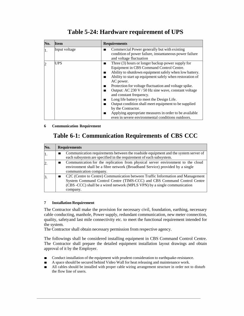
Table 5-24: Hardware requirement of UPS
No. Item Requirements
1. Input voltage ■ Commercial Power generally but with existing condition of power failure, instantaneous power failure
and voltage fluctuation
2 UPS ■ Three (3) hours or longer backup power supply for
Equipment in CBS Command Control Centre.
■ Ability to shutdown equipment safely when low battery. ■ Ability to start up equipment safely when restoration of
AC power.
■ Protection for voltage fluctuation and voltage spike. ■ Output: AC 230 V / 50 Hz sine wave, constant voltage
and constant frequency.
■ Long life battery to meet the Design Life. ■ Output condition shall meet equipment to be supplied
by the Contractor.
■ Applying appropriate measures in order to be available
even in severe environmental conditions outdoors.
6 Communication Requirement
Table 6-1: Communication Requirements of CBS CCC
No. Requirements
1. ■ Communication requirements between the roadside equipment and the system server of each subsystem are specified in the requirement of each subsystem.
2. ■ Communication for the replication from physical server environment to the cloud environment shall be a fibre network (Broadband Service) provided by a single
communication company.
3. ■ C2C (Centre to Centre) Communication between Traffic Information and Management
System Command Control Centre (TIMS-CCC) and CBS Command Control Centre (CBS -CCC) shall be a wired network (MPLS VPN) by a single communication company.
7 Installation Requirement
The Contractor shall make the provision for necessary civil, foundation, earthing, necessary
cable conducting, manhole, Power supply, redundant communication, new meter connection, quality, safety and last mile connectivity etc. to meet the functional requirement intended for the system. The Contractor shall obtain necessary permission from respective agency.
The followings shall be considered installing equipment in CBS Command Control Centre. The Contractor shall prepare the detailed equipment installation layout drawings and obtain approval of it by the Employer.
■ Conduct installation of the equipment with prudent consideration to earthquake-resistance.
■ A space should be secured behind Video Wall for heat releasing and maintenance work. ■ All cables should be installed with proper cable wiring arrangement structure in order not to disturb
the flow line of users.

Chapter 3-2 Requirements of Computer Aided Dispatch /
Automatic Vehicle Location
1 General
(a) Each bus shall be equipped with an On-Board Unit (OBU) for location tracking that incorporates
cellular data communications and sends frequent periodic location reports to the central operations
management system at the CBS Command Control Centre (CBS-CCC).
(b) These periodic location reports will provide ongoing information about current traffic speed on key
road segments, to serve as traffic probes data input to other systems.
(c) The CCC fleet operations management software will support the operation and effective use of a
Computer Aided Dispatch / Automatic Vehicle Location (CAD/AVL) system. This will enable
tracking of the route and schedule adherence for each vehicle, and the management/logging of
incidents.
2 System Configuration
The system configuration of CAD/AVL is shown in the figure below.
Figure 2-1: System Configuration of CAD/AVL
Following are the typical integration with proposed system with other system being
implemented in MTC.

Figure 2-2: Typical Integration of CAD/AVL System with other systems
Figure 2-3: Typical Integration of Depot Management System with other systems

Figure 2-4: Typical Integration of Incident Management System with
other systems
Figure 2-5: Typical Integration of Website & Mobile App with other systems

3 Equipment Location and Type
The onboard ITS device of CAD/AVL will be installed inside 2940 city buses of MTC. There will be additional 560 onboard ITS devices will be supplied and installed by another agency to be integrated by selected contractor with CAD/AVL, PIS and DMS.
4 System Functional Requirement
Table 4-1: System functional requirement of CAD/AVL
No. Requirements
GENERAL
1. Contractor shall conduct a detailed study of the ground situation and understand all aspects of rolling stock, infrastructure, operations, and management required for the various components of CAD/AVL.
2. System shall allow role-based access and shall be web-based application.
3. System shall provide read and write access for dispatcher to view and edit information
4. All active devices supplied as a part of the AVL System shall have self-diagnostic capabilities which can be initiated from the equipment and also remotely from the central
server at a pre- defined time each day (configurable) to know and generate the status and health of the equipment.
5. All applications proposed for City Bus System scope shall be web based applications. CAD/AVL CENTRAL SOFTWARE
6. Contractor shall provide all software and hardware that comprise the overall central system, including the required number of licenses for all users. The CAD/AVL software shall be provided outright with perpetual, royalty free license.
7. All data shall be the property of the Employer and shall be immediately available to the
Employer.
8. All servers shall be fully redundant and capable of automatic failover without administrator intervention.
9. System shall allow dispatcher to send message to multiple fleet vehicles simultaneously.
10. System shall allow dispatcher to select one vehicle, multiple vehicles, all vehicles, depot wise and service wise.
11. All workstation application software shall have the latest available operating system platform.
12. Preceding three years of data shall be retained in a historical database for use by management and other Employer’s staff to plan and assess system performance, and to address inquiries, conflicts and related issues.
13. The CAD/AVL software shall be installed on CCC workstations, and at required off-site locations for managerial staff to review the operations.
14. The CAD/AVL Application software shall be LAN based at the CCC and web-based
versions shall be available for offsite access. If the Bidder proposes web-based Software for the CCC, the Bidder shall show that the access speeds are satisfactory for the system requirements.
15. All CAD/AVL data shall be stored in a manner that allows direct access through the software for at least the preceding 180 days. Utilities shall be provided to support archive and restore functions for older data.
16. The onboard computer will send the location data every 10 seconds or at a user configurable
value, which central system software shall capture and process. Various alerts, to be finalized in the design stage, shall be shown to the dispatcher in real-time to help support operations.
17. GPS location data shall be transmitted using a 3G/GPRS connection to the central system software within 1 minute for all the vehicles.
18. The CAD/AVL system shall transmit the location data every 10 seconds to the probe processing module of Integrated Traffic Management System (ITMS) of Chennai Traffic

No. Requirements
Information and Management System Command Control Centre (TIMS-CCC) with suitable data format for the module.
19. During project implementation or maintenance, if the Employer find the cellular service used by the Bidder is not satisfactory, the Contractor shall migrate the SIMs to a better
service provider approved by the Employer at no additional cost.
20. The CAD/AVL system shall integrate with Depot Management System to maintain and receive updates for schedule, crew and fleet information.
21. If crew is on vacation, system shall able to identify his/her vacation and notify to operator to replace the crew.
22. Vehicle maintenance shall seamlessly integrate with Depot Management system so that no redundancy of master data exists between the systems.
23. The vehicle status list (e.g., headway adherence) shall be displayed capable of being sorted on any data field by the individual dispatcher.
24. Two-way voice communication from CCC to Vehicle: Central system software shall allow the through software. Dispatchers at CCC shall use headphones to talk to the crew.
25. Two-way voice communication from Vehicle to CCC: All the calls shall land in
EPABX/VoIP or similar Employer approved system so that multiple calls at CCC can be handled by the dispatchers.
26. All the two-way communication cost shall be borne by the Contractor for the period of the project including Maintenance period.
27. CAD/AVL system shall have System Audit trail feature.
28. CAD/AVL system shall interface with other ITS systems mentioned below and in the document. Contractor need to share the relevant data generated from CAD/AVL and DMS
with other systems mentioned below and receive & integrate with data that are required
during the design stage.
Incident Management System
Human Resource Management System
Fare collection system
Route rationalization
Maintenance management system
Workshop management system
29. AVL system shall provide centre-to-centre communications with ATCS (Signal) system when vehicles (MTC buses, emergency vehicles, VIP vehicles, etc.) traverse preset geo- fences. The AVL system shall provide information for the signal system to initiate Transit Signal Priority in a timely manner as per operational requirements.
Data Sharing with Traffic Information & Management System (TIMS)
30. CAD/AVL system shall be capable of sharing the bus probe data in GTFS format with the
probe processing module of Integrated Traffic Management System (ITMS) of Chennai
Traffic Information and Management System Command Control Centre (TIMS-CCC). The bus probe data shall contain the following data items as minimum.
(a) Minimum Items to be shared ✓ Bus ID
✓ Positioning Time (Time stamp at GPS device)
✓ Location Data (Longitude and Latitude)
✓ Ignition Status
✓ Vehicle Speed
✓ Harsh Braking
✓ Geofence triggers
✓ Vehicle Health & Monitoring parameter
✓ etc.
(b) Minimum Transmission Frequency
✓ 10 seconds or less
(c) Data Format ✓ Suitable format for the probe processing module of TIMS
MAPS

No. Requirements
31. The CAD/AVL system shall incorporate maps to support the functionality, comprised of a selection of individually selectable theme layers (e.g., stations, streets, names, water features, parks, major buildings). The base map shall be Google Maps or similar quality.
32. The CAD/AVL system shall have a smart search feature to filter the data shown by the software.
33. The Bidder shall develop a GIS based base map for the project at a scale of at least 1:2500 or better resolution operationally.
34. The system shall include mechanisms to allow for periodic independent updates to the central software maps.
35. Fleet icons on the Map shall show the direction of travel of each bus in real-time.
36. The client shall be able to develop additional overlay map layers to the external source map that shall include polygons (e.g., municipal boundaries, fare zones), lines (e.g., route traces) and points (e.g., landmarks, transfer locations, time-points, stops), with the color, shape and thickness being selectable.
37. Map shall have a tool to measure the distance through mouse clicks.
38. Software shall allow authorized Employer staff to create, modify and delete the Points of Interest and Geofencing on the Map.
39. The Employer shall help to identify the locations of bus stops, bus stations, terminals, depots, etc. to the Contractor. Bidder is responsible for carrying out the necessary surveys and bearing the cost of equipment, persons, transportation, etc.
40. The software shall allow users to view the map, including a selectable combination of the source map layers and new layers, at various user-defined zoom levels.
41. The system shall receive location reports from each vehicle. The system shall use the time stamped location reports in combination with schedule data to derive the current schedule adherence status.
42. Application shall have reasonable filters to track the vehicle movement in real time
43. Application shall allow dispatcher to select multiple vehicles using mouse clicks. Dispatcher shall be able to send group messages or conduct voice call to the selected vehicles in one shot.
44. Application shall be capable to figure out where bus had deviated from and rejoined the defined route and show this on the map.
45. The system shall receive and store latitude and longitude information together with the associated schedule adherence, stamped with date, time, vehicle, schedule, route, and store this data.
46. Information shown along with the vehicle on the map shall be user selectable. The User shall have the option of selecting to display vehicle number, route, schedule, speed, delay time, etc. with the vehicle. The actual parameters are to be defined during design stage by Bidder through discussion with the Employer.
47. The display icon of the bus on the map shall provide an indication if the latest reported location being displayed is older than the reporting interval or not.
48. The display icon of the bus on the map shall provide an indication in different colour based on current bus status
• On time
• Late
• Early
• Over speeding • Route deviation
• Last report older than reporting interval
• SOS Alert
The details to be defined during design stage by Bidder through discussion with the Employer.
49. The system shall track headways for each individual route.
50. Schedule Adherence shall be based on Planned Schedule vs. Actual schedule using mainly automated geofence data of trip ends. Additional, time-based adherence of schedule should

No. Requirements
be implemented to ensure Operational challenges that are commonly seen in Indian conditions.
51. Based on configurable thresholds, the system shall use the observed headways to report to dispatcher using a real-time alert when headways are shorter or longer than desired range of
headway.
52. The system shall highlight the vehicle IDs of those vehicles operating with out of tolerance headway, using tabular and map displays to indicate the current headway adherence status.
53. The tabular display entries and the map display symbols for these vehicles shall use distinct and configurable colour codes for short headways and long headways status.
54. Map should refresh the vehicle location on every 10 seconds interval. The application shall allow the Employer to reconfigurable this reporting interval at any time without need for code or program change.
55. The system shall provide a real-time output of the current location and schedule adherence for all fleet vehicles, for use by the stop arrival prediction software.
56. More than 70% of the predictions for Estimated Time of Arrival made 15 minutes before the bus arrival shall have accuracy between -2 to 7 minutes. The thresholds shall be
reassessed during operations for better passenger confidence on the predictions. 57. ETA should be shown for buses across Trips based on selected schedule.
58. Estimated Time of Arrival shall be calculated and displayed on the PIS display board located at terminals, bus stops/shelter and interchanges in real time.
59. In case of vehicle breakdown or other incident being logged by the dispatcher, the system shall record the event and send an alerting SMS to configured persons.
60. Contractor shall document and provide to the Employer the communications protocols,
command sets and message formats used in all interfaces.
61. On left/right click of the mouse, the following vehicle information, at a minimum, shall show on the Map:
• Vehicle Number
• Contact no of Crew • Current Trip/Schedule no
• Current Delay
• ETA for minimum of next 3 stops
• Last stop
• Next approaching stop • Last GPS time stamp • Current Vehicle status • Current Speed
62. All the alerts shall meet MTC business requirements. Various alert types as explained below, shall be discussed and finalized during design stage.
63. Alerts to the dispatchers shall be configurable by authorized MTC staff.
64. Dispatchers shall have ability to filter or sort the alerts by type.
65. By double clicking the vehicle icon the CAD/AVL application shall provide the history of all alerts throughout that day for that vehicle.
66. Alert window shall have option to show recent alerts for specified preceding time, that entire day or for preceding 3 months.
67. The CAD/AVL Application GUI and map should interface to provide extensive alerts required for real-time operational support. If required the following alerts shall be sent by
Email and SMS to the configured Employer staff (ex: Service and Maintenance Alerts). For critical alerts the system will also generate an audio alert. Following is the tentative list,
which may be updated or added to during the design and implementation period:
I. Critical Alerts (SOS) a. Ambulance Required
b. Accident/Breakdown/Fire c. Bus stopped idle for x minutes during the Trip (Time must be configurable by the Employer)
II. Major Alerts

No. Requirements
a. Bus running without Schedule/Trip on the Road
b. Route Deviation Alerts c. Schedule Adherence Alerts – colour coded by gap time
d. Bus Bunching Alerts
e. Speed Violation
III. Vehicle Status Alerts
a. Over Speeding b. Tamper Alert
c. Harsh Acceleration d. Harsh Braking
IV. Service and Maintenance Alerts
a. Crew license expiry
b. Vehicle FC renewal c. Vehicle routine maintenance d. Vehicle insurance and road permit
68. • The CAD/AVL Central Software shall display the following information, at a minimum, for a selected stop(s):
• Stop ID;
• ETA for the next ‘x’ number of buses, where x is configurable through the application.
• Routes servicing the stop; and • Number of buses that shall arrive as per Schedule in the next x minutes, where x is
configurable through the application.
69. The Alerts shall be easily identified on the map through double-clicking of the alert. Location playback features shall be available on clicking of Alerts.
LOCATION PLAYBACK
70. The dispatcher shall be able to review on the map display the chronological sequence of reported locations for a specified vehicle over a specified time period.
71. The software shall provide controls to view the entire sequence of reported locations from the beginning of the time period or to step through the sequence incrementally forwards or backwards.
72. The system shall allow replay for a single vehicle, selected set of vehicles or all vehicles on the selected map view for selected time period. Selection can be time period, or area in which vehicles arrive or a combination of both.
73. System shall include multiple features for location playback, to allow variable speeds and time period selections for ease of replaying.
74. The system shall allow selection of any time period for playback using the historical data.
75. Replay functionality shall have necessary filters for dispatcher to find the vehicles
76. The replay data shall include location and schedule/headway adherence data.
77. All users accessing the CAD/AVL software shall be able to access the playback function.
78. Replay functionality to support vehicle with or without an assigned schedule/trip.
79. The system shall allow the ability to use playback without exiting from the current CAD/AVL operational view.
80. The system shall be able to store a playback in a format that can be exported for viewing on any computer.
Data Logging and Retrieval
81. All incoming and outgoing data shall be stored for retrieval, analysis, display and printing.
82. The system shall allow all such data to be retrieved, even if it has been archived.
83. This historical information shall include all reported and derived data for vehicles (including at minimum the date/time, vehicle, schedule, route, trip, location data, schedule adherence data, headway adherence data, station/stop arrival predictions); and all central software user logons and logoffs.
84. The system shall include a means of archiving transaction data, or restoring data from an archive, while the system is in operation.
85. It shall not be necessary to shut down the database to perform a successful back-up operation.

No. Requirements
86. The stored data shall enable accessing the historical data from both the online and archived storage, and selective sorting and retrieval based on user-specified criteria for any of the fields.
87. Historical data shall be read-only with modification only permitted to individual pre-defined fields, with prior approval from the Employer
CAD/AVL GUI REQUIREMENTS
88. The central system shall be delivered with a fully functioning Graphical User Interface (GUI).
89. The GUI shall be based on standard Windows controls or equivalent.
90. Scheduling and rescheduling shall be very convenient for day to day operations for the dispatcher.
91. Dashboard: Multiple dashboards shall be created based on dispatcher category. At minimum
preceding month, preceding week, preceding day, current day. The dashboards shall be
made available as soon as dispatcher login and there should be option to include dashboard access in the menu.
92. All screens with paging data shall open and populate with the initial data in 3 seconds and thereafter page updates shall be retrieved within 1 second.
93. Dragging the cursor bar for a scrollable list shall cause instantaneous redisplay of the list in time with the movement of the cursor bar.
94. A single screen shall show the vehicle no, vehicle status, last stop, and last GPS timestamp received
95. All the buses within the map view shall be shown concurrently in the GUI with both static and real-time data
96. Multiple configurable views using the GUI shall be available for the dispatcher, available for retrieval through a dropdown list.
97. The hover features should be present giving an indication of the main vehicle movement
characteristics in real-time, which shall include at minimum the current speed, distance
travelled, next nearest stop, delay if any, trip number etc. These parameters should be also configurable easily, to display system features as required by the Employer.
98. CAD/AVL GUI shall use line diagrams to show dynamic status of all vehicles along a selected route.
99. Various master data files should be available through the CAD/AVL GUI. These include but not limited to:
I. Schedule Master
II. Route Master III. Bus Stop Master
IV. Depot Master (for future requirements)
V. Crew Master
VI. Onboard Computer Master VII. PIS Master VIII. Landmark Master
PREDICTION SOFTWARE REQUIREMENTS
100. The system shall use the real time location and schedule adherence data to create a continuously updated table, XML data feed and GTFS real-time data stream of the last reported location for all vehicles and the next arrival predictions within the Employer’s configurable upcoming time window for all stations/stops
101. The system shall provide this data table and XML data feed and GTFS real-time data feed to which the Employer and designated third parties have the right to perpetual and royalty-
free access, for the purposes for integration with future Passenger Information System (PIS) or other public information methods and importing data into the long term database.
102. The Bidder shall also provide a data dictionary and Entity Relationship Diagram for the data tables and XML schema documentation.
103. The information required by the algorithm(s) shall be manually entered into a prediction support database by the Bidder.
104. The system shall allow the user to configure the prediction support database values.

No. Requirements
105. A system report providing accuracy predictions stratified by minutes in advance of the arrival, filtered on a stop and time period basis, shall be provided to enable accuracy assessment during and after the implementation. With such a report, the Bidder shall still be required to assist with sufficient field data collection to validate the system prediction
accuracy report, as well as with efforts to use the report data to maximize the accuracy of the arrival predictions.
SYSTEM SECURITY REQUIREMENTS
106. The Central System & CCC Workstation shall only be accessible by authorized persons, controlled using login and password protection.
107. It shall be possible to create multiple user classes with different privileges.
108. The system shall maintain a transaction log that records when each user accesses each report, any edits and changes to the database, and the system logon and log-off times.
109. The transaction log shall maintain this information for a minimum of one year.
110. The system security shall provide features to maintain data integrity, including error checking, error monitoring, error handling, and encryption.
111. Features shall be provided to automatically detect, correct and prevent the propagation of invalid or erroneous data throughout the system.
112. All systems, sub-systems and devices shall only allow access to authorized user classes.
113. All security breach detections shall be confidential, and accessible only to users of the appropriate class.
114. The Central System shall be capable of data communication with all system components in real-time.
115. The central system shall update its date and time by applying time synchronisation to servers using the internet and using this to in turn update the date and time on all onboard computer and PIS Displays.
116. The central computer system shall manage all device activity including data storage and processing.
117. All active equipment shall have an internally maintained date and time clock synchronized at
a time interval via the communications controller with the Central System date and time clock.
118. The time synchronisation application in the device shall have the capability to adjust the minimum time interval to update itself with the central system time and date, and shall be able to update time every minute (configurable) with the central system.
119. All mobile equipment (onboard computer) shall operate with a real-time data connection to the central system via the communications (GPRS) network
120. If the data connection to the central system is temporarily lost, all equipment shall seamlessly switch to an offline mode in which all data is temporarily stored in internal memory and transmitted to the central system as soon as the data connection is re- established.
121. All equipment shall have sufficient memory to operate in offline mode, with no loss of data, for not less than 168 hours.
122. It shall be possible to “future-date” messages to PIS systems so that they can be uploaded ahead-of-time and automatically displayed during the planned date and time.
123. The central software shall provide over-the-air updates & firmware updates to all devices, separate from other immediate critical updates.
124. The systems shall be driven by configurable parameters and shall provide the flexibility for maximum configuration. The configurations shall consist of, but not be limited to:
a. Time based messages
b. User Groups and user privileges c. Addition & deletion of onboard computer, PIS nodes, user groups, users d. Configurable messages in English and Tamil languages e. Reports access
125. The system shall handle all exceptions. Exceptions can be, but not limited to: a. Message not being displayed on the PIS

No. Requirements
b. Triggers for panel opening of any equipment c. Default message shall be configurable in case of the lost central connectivity
126. The system shall handle all degraded conditions, including but not limited to: a. Any supplied equipment not functional
b. Power failures c. Data Connection lost d. Central Server down
MAINTENANCE MODE – OPERATIONAL REQUIREMENTS
127. The Central system and all the equipment (on-board ITS equipment, PIS displays in terminals, bus stops/shelters, etc.) shall support a maintenance mode for use during repair, replacement and testing of equipment.
128. The maintenance mode shall have feature to be activated by only a person having the highest user privilege in terms of system operations.
129. Logins and logouts shall be transmitted to the central system, along with associated Date/Time, employee ID, equipment ID etc.
130. It shall be possible to upgrade the firmware/software of the onboard computer from the central server using the communication network.
131. System shall allow update for configuration changes at multiple fleets onboard computer over the air.
132. The Employer shall be the owner of all system data and able to use the central system to export transactions data for processing/analysis using other software.
133. Data received from system devices shall be maintained at the original level of transactions and not be aggregated, consolidated, or combined within the database.
134. Sufficient data storage capacity shall be provided in the central system to store online a minimum of two years activity data.
135. All data shall be automatically backed-up daily without human intervention, using the backup devices and media. Bidder shall provide all needed data cartridges, as required during O & M period.
136. Means shall be provided to automatically archive data older than two years using the archiving media.
137. The system shall use archived data to process comparative reports, such as but not limited to reports utilizing and comparing data from non-consecutive month periods in two different years, or day-of-week comparisons over multiple month or annual periods.
138. The transactional database shall store the date/ time stamped details of all information transmitted to the central system from system devices.
139. In addition to transaction records, the database shall incorporate additional tables to record
information of interest, including but not limited to:
a. Device locations (e.g. PIS Displays) b. Diagnostic/maintenance data (such as error records) c. Exception data (e.g. alarms, memory clears)
SCALABILITY/FUTURE OPERATIONAL REQUIREMENTS
140. The central software shall be scalable to accommodate 6000 buses, 5000 bus stop PIS display, 250 PIS boards at terminal, DMS solutions up to 50 depots without any
modifications to the central software except minor configuration changes, with the details of how scalable the system is provided in the proposal by the Bidder without any additional cost to the Employer. No additional amount will be paid for the software components for the quantity mentioned here.
141. Employer plans to implement several other service or feeder routes in future, for which the
existing central system shall be used, by including only additional hardware for additional buses as per the requirement.
142. Contractor shall be able to generate all reports separately for every service under operation.
143. Contractor need to provide additional 1 TB storage to store the data that are received from various other systems like. Fare collection, Route Rationalization, any other application expected to integrate with CAD/AVL, PIS & DMS.
MIS REPORTS REQUIREMENTS (BUSINESS INTELIGENT APPLICATION)

No. Requirements
144. The Contractor shall provide latest version of proven Data analytics/BI tool to analyze and
provide the data to MTC in detail. Contractor shall provide details in their proposal related to reports offered and the degree to which they can be configured (at minimum all reports shall
be configurable for a specified date/time range and routes or schedules or service type). Summary
reports for different levels of management staff shall be designed by Bidder during the design stage. Automated graphs/plots for commonly used data shall be provided in discussion with
the Employer. Following are tentative list, this may be updated/added during design and implementation period:
1. Schedule adherence at depot, terminal and various selected bus stops/stations 2. Headway adherence/Bus bunching report
3. Active fleet (weekday and weekend)
4. Service hours and mileage 5. Speed violation reports
6. Alerts reports
7. Missed/Cancelled Trip
8. Route Deviation 9. Dead KMs report 10. Vehicle Distance Travelled as per schedule/ trip/ charted trip
11. Bus stop skipped
12. Improper stop report
13. Daily bus out shedding report 14. Bus breakdown report
15. Depot IN/OUT report 16. Monthly summary reports broken down by system, division, depot, route, bus type,
driver, conductor, bus make, etc.
17. Bus Location by date/time, location, and other parameters 18. Driver performance report consisting of bus stop skipping, harsh acceleration, harsh deceleration, over speeding, etc.
19. Fraudulent activity reports with the hardware (Tampering reports)
20. Faults and errors 21. Bus trip reports;
22. System exceptions reports
23. System performance and activity reports 24. Financial reports SLA violation report based on the business rules specified in bus operations tender.
25. Travel time reports between stops.
26. Reports on events that hinder movement of buses. 27. Consolidated GPS analysis report – service provider wise
28. Consolidated GPS analysis report – vehicle wise, depot wise, service wise
29. Historical reports
a. Employee detail b. Vehicle detail c. Bus stops d. Bus stop names by route
145. The Contractor shall be able to collect all the required data from the onboard computer to generate the required PIS display data and MIS reports.
146. The software shall have the capability to generate reports based on exceptions as per thresholds set by the Employer staff for various CAD/AVL components.
147. Reports shall have summary and detail information based on the Employer needs.
148. The Contractor shall provide tools to generate ad-hoc / custom reports on stored CAD/AVL data.
149. All reports must use standard reporting tools similar to Apache Spark, Hadoop, IBM IoT
framework, Microsoft Azure, and have the ability to export data into file formats that can be exported to and edited with standard office software (e.g., Microsoft Word and Excel, Adobe Acrobat .PDF)

No. Requirements
150. Any portion of the transactional database shall be exportable in standard formats (such as .csv, xls, xlsx, xml, etc.) for analysis in third party programs.
151. It shall be possible for users to build custom reports from the data in the transactional database with support. The reports should be customizable for various time periods through the dashboard of the reporting system.
152. A data dictionary shall be provided to the Employer to facilitate development of custom reports.
153. The Central System shall provide sufficient summarized and detailed data, including features to generate standard reports based on pre-established criteria, as well as as-required
reports based on a user-definable set of search criteria.
154. All reports shall be generated using a query language and standard query engine (to be
approved by Employer) that provides flexibility for future updates, and for creation of new reports. BI Analytics capability must be in-built in the platform without usage of additional COTS product or additional integrations
Platform must be capable of providing slice and dicing capability using the visual representations and actions available in the dashboard widget system
Platform must be capable of analyzing the data coming from different domains and the different sub-systems
Platform must have user friendly BI tool for manual as well as automated analytics. Platform must be capable of mashing the data from different domains and different
sub-systems, and thus provide cross-domain analysis capability
The Analytics engine must be an artificial intelligence-based module to maximize
business value through advanced machine learning capabilities. The machine learning capabilities must aid in operations management and result in better outcomes.
Analytics Engine must have automatic Model training and retraining capability and should not have any manual intervention
Analytics Engine must be able analyze the simulated data, train the models using simulated data and predict the possible outcomes
Based on data analyzed from multiple data sources of the city, Analytics Engine must provide recommendations which can derive value/outcomes in terms of revenue
optimization and cost savings for the city.
155. Reporting software shall include the ability to generate graphs and charts based on criteria and format defined by the user
156. All reports shall be generated with configurable time parameters, including as a minimum annual, monthly, weekly, daily, hourly and with user defined start-end date and time ranges
157. As a minimum, the Central System shall generate required standard reports daily, weekly, monthly, quarterly and annually. These reports shall be available through the CAD/AVL Software.
158. The Contractor shall provide an ad-hoc reporting function and interface into the data and
reports server to allow the Employer personnel to create, execute and receive custom reports
without Bidder assistance. An Internet-based interface shall be provided for this function, accessible by the Employer personnel with appropriate permissions. The Employer users
shall be able to generate ad-hoc reports and do additional analysis of ridership, revenue and
other System data. The Bidder shall enable The Employer staff to generate reports and use the system. Examples of the types of reports include: a. Transaction-level reports by stop and for user-defined start and end points; b. Statistical and research reports using user-defined criteria.
159. It shall be possible to aggregate data (filter) for reporting, at a minimum, by:
a. Date/Time b. Origin
c. Destination
d. Location e. Equipment Serial Number f. Vehicle number g. Crew Name

No. Requirements
It shall not be necessary that values be consecutive for the purposes of aggregation (e.g. non- consecutive months).
160. The actual bus operational business rules will keep varying and the Employer shall periodically share these with the selected Bidder, which the Bidder shall reflect in the CAD/AVL application for generating any additional reports during the project period.
161. The Software shall be capable of establishing automatic periodic (monthly/quarterly/yearly) routines to automatically produce and email standard reports to defined user groups.
162. The Software shall provide a web-based reporting tool to allow for access from anywhere. The access and views of the reports will be based on role based access control.
163. Software shall allow The Employer to generate Summary and Detail reports as applicable. PERFORMANCE REQUIREMENTS
164. Server hardware and licenses shall be sufficient for up to 50 dispatcher work-stations to access the central software concurrently, with no loss of performance.
165. Contractor to arrange and provide application, software and antivirus licenses as per
numbers mentioned in system inventory table. If any additional licenses are required as per
the system design approved for the Contractor then Contractor to provide necessary licenses without any additional cost.
166. The central software shall be scalable to accommodate 6000 buses, 5000 bus stop PIS display, 250 PIS boards at terminal, DMS solutions up to 50 depots without any modifications to the central software except minor configuration changes, with the details of how scalable the system is provided in the proposal by the Bidder.
167. The servers shall have capacity to process 300,000 service transactions/hour
ON-BOARD ITS (onboard computer) Interface with AVL Application
Single Control Unit (SCU) / Bus Driver Console (BDC)
168. Contractor shall provide the end to end support to integrate with central system software. This hardware shall have UBS II or equivalent specification. Following hardware would be
supplied: • SCU • BDC
169. The city services are existing buses for which the Bidder shall supply, install and
operationalize the SCU, BDC and two-way communication (audio interface) system. The SCU, BDC and audio interface shall be compliant with UBS-II requirements or have equivalent standards that are acceptable to the Employer.
170. At the onset of the project, the Bidder shall study the power surges on cold cranking of buses using OCR and design the SCU to withstand these surges. A report on the surges in various types of buses shall be provided to the Employer before SCU installation.
171. The Contractor shall provide for the CBS equipment: • Communication protocols: The SCU communications shall be based on open protocols.
Contractor shall provide the protocols, API and interface documents to the Employer before system acceptance or when it was asked by the Employer.
• Installation: The installation of the CAD/AVL equipment shall be done professionally. The
BDC shall be installed such that it is can be comfortably viewed and touched by a range of drivers during vehicle operation.
• GUI Customization: BDC GUI shall be customized for the Employer requirements. Customization is for making the BDC support the CBS operations to be undertaken by the Employer, including showing selected information in the local language.
• A timer shall be provided with SCU so that the SCU can be switched off after a variable set period (1 minute to 2 hours) after the bus ignition is switched off. The timer shall help
protect the life of the bus battery, while ensuring file transfers can be completed in the depot after the bus ignition is switched off.
172. The onboard computer firmware shall be able to update over the air (OTA) from CAD/AVL central system software at Command Control Center.
173. Contractor shall understand the MTC requirements and develop the interface for BDC as mentioned below at a minimum:

No. Requirements
• BDC interface shall mainly be graphical and shall support both the language Tamil and English to be selected between by crew at their convenience.
• Login for driver through pin number to be entered using BDC
• Route selection function is to be provided on BDC • All driver related route information to be displayed on BDC • Alerts of harsh braking, harsh speed, harsh acceleration, route deviation, speed violation, shall be sending to BDC from central system software.
• BDC shall provide basic map of Chennai city and Rural. Using that crew can see the
vehicle location.
• BDC shall provide a line diagram of the route with a current vehicle location and where
the vehicle should be present as per schedule, in real-time. Clear graphical indication of on- time/early/delayed performance shall be provided through colour coded thresholds.
• Next stop name with distance • Application shall able to send route and its related information to BDC. Route selection could be automated or manual selection based on MTC business requirement, this would be discussed and finalized during design.
• SOS: Multiple SOS messages shall be provided to crew to send to CCC. • Depends on SOS type dispatcher shall be able to acknowledge the SOS received from bus.
• SOS interface developed by Contractor shall support that if required SOS messages shall
be passed to multiple staff from central system software.
• Two way voice communication: interface shall support making two way voice communications from vehicle to CCC or CCC to vehicle.
• Two way voice communication: Interface shall support only registered number can make
outgoing and incoming call to the vehicle.
174. The onboard computer shall be able to automatically pull the route information from the central system software depending on the operations schedule associated with a particular bus.
175. The onboard computer shall send the current location report as determined by the GPS receiver over the 3G/GPRS network to the Central System, at an interval specified by the
Employer. The Employer shall be able to choose a location report interval, with a minimum of 10 seconds.
176. The onboard computer shall detect if the vehicle stops for more than x minutes
(configurable) at a location other than a station or a traffic signal or any other pre-defined
location and send a time stamped report of this occurrence to the central system. If this occurs when the vehicle is not in cellular data coverage, this report shall be sent as soon as cellular coverage is acquired.
177. In case of reported vehicular stoppage, the interface shall be able to allow the reasons for such delay and exclude such delays due to unforeseen conditions to be excluded by
impacting the penalties of the bus operator. However, such exclusions shall be possible only to be included by the Employer.
178. SCU is capable to store waypoint data. CAD/AVL central software shall be able to pull the bulk data from multiple SCU.
179. Contractor shall ensure that selected service provider for the cellular data network(s) shall have complete coverage in Chennai, acceptable to MTC.
180. Interface shall be developed by the Contractor to integrate the SCU and BDC with central system software to display information in Tamil or in simple enough graphical form that the Crew can comprehend it with minimal training.
181. Contractor shall provide connectivity between the onboard computer and the existing vehicle CANbus to enable the onboard computer to monitor CANbus messages.
182. Contractor shall develop and customize the onboard computer application to monitor and
interpret all messages on the existing vehicle CANbus, including the ability to configure actions to take to store and/or send data when configured messages are detected.
183. Data received from the onboard computers as a resulting of this CANbus messages
monitoring bus shall be stored by the central software. And shall be transferred for use by vehicle maintenance software provided by others for data processing and analysis purposes.

No. Requirements
184. Contractor need to develop and customize onboard computer application to support the integration of following components without any additional cost as on when required.
In-bus PIS board
In-bus Surveillance and analytics
Vehicle Health Monitoring and Diagnostic device using CAN bus protocol
In-bus announcement system
In-bus Route boards Existing Variable Message Boards installed in Chennai
185. In-bus route boards shall display Expected Time of Departure (ETD) while buses standing at the terminals.
186. Currently safe city project being implemented in MTC for 2500 buses. Selected bidder is expected to integrate Onboard Computer (SCU) with Mobile NVR installed in the bus to transfer the Video data to control centre where Video Management System is running.
187. Currently MTC is planning to buy additional buses which will have UBS II specifications similar to SCU and BDC mentioned in this document. Selected bidder is expected to integrate along with this scope of work.
188. Single Control Unit shall be capable of storing at least 8000 schedules in it.
189. Change of schedule by crew through BDC shall not be allowed without acknowledgement by the dispatcher/branch manager or designated person of MTC.
5 Hardware Requirement
All hardware equipment shall as a minimum, meet all the requirements listed in the specifications. The equipment’s provided shall accommodate to future technological advances which exceeds the minimum requirements provided in the specifications.
5.1 Onboard ITS Device (SCU & BDC)
Table 5-1: Hardware requirement of Onboard ITS device (SCU & BDC)
No. Onboard ITS Device (SCU & BDC)
1 (1) Single Control Unit
■ Processor: 32/ 64 bit ■ Operating system: embedded Windows/Linux with programming software (Windows 7
or latest at the time of calling the tenders)
■ Memory: flash: 2 GB minimum, RAM 512 MB minimum (RAM memory includes SCU and BDC)
■ Interface: CAN 2.0, RS 485, RS 232, fast Ethernet, USB, digital outputs, digital/Analog
inputs, WLAN, audio input output, amplified audio output
■ Interface protocols: as specified elsewhere in this document
■ In built GPS and 3G(GSM) modules
■ WLAN ■ Combi antenna using RG174 cable. The connectors on Combi antenna will be preferably
SMA(M) ST plug type for GPS and FME(F) jack type 1/4"-36UNS-2B for 3G
■ In built /external two channel amplifier minimum 10 Watts rms each suitable for 4 ~8 Ohm impedance with input for external microphone
■ In-built MP3 files storage/playback function.
■ Power to SCU & BDC will be supplied through bus multiplexing wiring system
(2) Technical specifications: GPS modules
■ Rating:22 tracking/66 acquisition minimum ■ Tracking sensitivity: -165 dBm typ
■ Navigation sensitivity; -148 dBm typ
■ Update rate I Hz (configurable to 10 Hz) ■ Time to first fix cold acquisition 35 seconds typ ■ Hot acquisition 1 second typ.

No. Onboard ITS Device (SCU & BDC)
■ Navigation accuracy 3M horizontal
(3) Technical specifications: 3G(GSM) modules
■ GSM/GPRS SMT quad band and UMTS (3G) ■ Temperature range -40°C to +85°C
(4) Technical specifications: ‘Combi’ Antenna
a. AMPS 850MHz, GSM900MHz, ISM868MHz, DCS1800MHz,
PCS1900MHz, 3G UMTS 2.1GHz, Wifi /Blue Tooth (2.4 GHz), GPS (1575.42MHz). Separate WLAN antenna may be provided if necessary.
b. GPRS
i Impedance 50 Ohm
ii Radiation pattern Omni-directional
iii Polarization linear (vertical)
c. GPS
i Impedance 50 Ohms
ii VSWR <1.5:1
iii Polarization RHCP
d. Waterproof IP-66 e. Temperature range -40°C to +85°C
2 Technical Specification: BDC
a. Display
i Size 8” diagonal minimum
ii Full color graphic TFT-640 x 480 dots minimum, capable of showing minimum 10 lines in English.
iii Viewing angle (horizontal) 60°/75° (right/left)/ (vertical) 60°/75° (up and down)
5.2 Workstation for CAD/AVL at Depot
Table 5-2: Hardware requirement of Workstation for CAD/AVL at depot
No Parameter Requirements
1. CPU Quad core CPU with 8 threads or equivalent or better
2. Memory 8 GB DDR4 or better
3. Hard-Disk Drive 512 GB SSD or better
4. Display One number 21”-inch LCD / LED Display
5. Display ports 4 Display Port / mini Display Ports Toolkit/Stand to install the dual monitors
6. GPU Base clock: 1290 Mhz or better Number of cores: 768 or better VRAM: 4GB or better Display connectors: DP 1.4, HDMI 2.0b, dual link-DVI multi- monitor support Max resolution: 7680 x 4320 @ 60 Hz or better
7. Keyboard Wired keyboard with 104 keys
8. Mouse Wired Optical with USB interface
9. Ports USB Ports including 2 USB 3.0 Ports and audio ports for microphone and headphone
10. Cabinet Mini Tower.
11. Operating system Windows 10 64-bit operating system
12. Software Tools Microsoft Office 365 or equivalent
13. Antivirus To be provided

5.3 UPS
Table 5-3: Hardware Requirement of UPS
No. Item Requirements
1. Input voltage ■ Commercial Power generally but with existing condition of power failure, instantaneous power failure and voltage fluctuation
2 UPS ■ three (3) hours or longer backup power supply for Workstation for
CAD/AVL at Depot
■ Ability to shutdown equipment safely when low battery.
■ Ability to start up equipment safely when restoration of AC power.
■ Protection for voltage fluctuation and voltage spike. ■ Output: AC 230 V / 50 Hz sine wave, constant voltage and constant
frequency.
■ Long life battery to meet the Design Life. ■ Output condition shall meet equipment to be supplied by the
Contractor.
■ Applying appropriate measures in order to be available even in severe
environmental conditions outdoors.
6 Communication Requirement
Table 6-1: Communication Requirements of CAD/AVL
No. Requirements
1. ■ Communication between the CAD/AVL server in the CBS CCC and the on-board unit shall be Wireless 3G/4G or upcoming 5G Connectivity provided by a single communication company.
■ The required bandwidth to ensure the stable communication connectivity shall be proposed by the Contractor and subsequently approved by the Engineer.
7 Installation Requirement
The proposed onboard device consists of two connected units one is computing device, and another is its driver display console peripheral. Computing device will be installed with less access to commuters/public, in a location where it will have access to vehicle power/ground and be accessible to remove for maintenance/replacement.
Driver display console will be installed on the dashboard of the bus within comfortable reach and view for the range of driver sizes, and without vibration or obstructing the driver view. During Operation & Maintenance stage contractor require to uninstall and reinstall the onboard device as required by MTC.
All required cables, connectors and accessories to be provided by the Contractor.
The Contractor shall make the provision for necessary earthing, cable, communication,
quality, safety to meet the functional requirement intended for the system.

Chapter 3-3 Requirements of Passenger Information System
1 General
(a) The Passenger Information System (PIS) will use the route and schedule adherence
tracking information to provide information about predicted arrival times on PIS at
terminals and bus shelters visible to waiting riders. And providing this real-time
information through a website and mobile application.
2 System Configuration
The system configuration of PIS is shown in the figure below.
Figure 2-1: System Configuration of PIS

3 Equipment Location
The proposed locations for PIS are shown below in the Table. The Contractor shall adhere to
the proposed locations as much as possible to satisfy the above requirement. In case of any changes in the locations the Contractor shall get the written approval from the Engineer based on the alignment, geometry, viewing area (based on site visit). Following are the tentative terminal and bus shelter locations.
Table 3-1: Tentative terminal and Bus
Stop/Shelter locaitons
S. No Bus Terminal Name No. of Boards
1 Adyar 1
2 Adambakkam 1
3 Ambathur Estate 1
4 Anna Nagar West 2
5 Avadi 1
6 Ayanavaram 1
7 Besant Nagar 1
8 Ennore 1
9 Foreshore Estate 1
10 Iyyappanthangal 2
11 Vallalar Nagar 3
12 J.J.Nagar East 1
13 J.J.Nagar West 1
14 K.K.Nagar 1
15 K.Kannadasan Nagar 1
16 Kannagi Nagar 1
17 M.K.B.Nagar 1
18 M.M.D.A. 1
19 Mandaveli 1
20 Perambur 2
21 Periyar Nagar 1
22 Semmenchery 1
23 T.Nagar 1
24 T.V.K Nagar 1
25 Thiruvanmiyur 1
26 Thiruverkadu 2
27 Thiruvotriyur 1
28 Tollgate 1
29 Vadapalani 1
30 Villivakkam 2
31 Padiyanallur 1
32 Ambathur O.T. 1
33 Anna Square 1
34 Broadway 2
35 C.M.B.T. 2
36 Central 1

37 Chengalpet 1
38 Egmore 1
39 Guduvanchery 2
40 Guindy 2
41 Hasthinapuram 1
42 I.C.F. 1
43 I.O.C. 1
44 Karanodai 1
45 Kelambakkam 1
46 Kilkattalai 1
47 Korattur 1
48 Korukkupet 1
49 Kovalam 1
50 Kundrathur 2
51 Manali 1
52 Madhavaram Village 1
53 Mamallapuram 1
54 Medavakkam 1
55 Minjur 1
56 Pallavaram 1
57 Pattabiram 1
58 Periyapalayam 1
59 Poonamallee 1
60 Pozhichalur 1
61 Pudur 1
62 Red Hills 1
63 Saidapet 1
64 Sanatorium 1
65 Sriperumbudur 1
66 Tambaram 1
67 Thiruporur 2
68 Thiruvallur 1
69 Vandalur Zoo 1
70 Velachery 1
71 Vevekananda House 1
Total 84
Bus Stop/Shelter Location Names:
S. No Bus Shelter Name No. of Boards
1 Broadway 2
2 Parrys corner 2
3 Secretariat 2
4 War memorial 2

5 Marina Beach 2
6 Kannagi Statue or presidency
college 2
7 Swami Vivekananda House 2
8 Queen Marys College 2
9 All India Radio Light House 2
10 Simson or Periyar Bridge 2
11 Shanthi Theatre 2
12 LIC 2
13 Spensor Plaza TVS 2
14 Anand Theatre 2
15 Thousand light 2
16 DMS 2
17 Vanavil 2
18 SIET 2
19 Nandanam 2
20 SHB 2
21 Saidapet 2
22 Saidapet bridge 2
23 Little Mount 2
24 Concorde 2
25 Chellammal College 2
26 MGR Medical University 2
27 Guindy Railway station 2
28 Maduvankarai 2
29 Guindy MKN Salai 2
30 Prnaipalai 2
31 St. Thomas Mount 2
32 Alandur Court 2
33 Alandur 2
34 Meeanambakkam Airport 2
35 Thirusoolam 2
36 HP Petrol Station 1
37 Central Station 2
38 Hotel Everest 2
39 Thinathanthi 2
40 Dasaprakash 2
41 Sangam Theatre 2
42 KMC Hospital 2
43 Taylors Road 2
44 Pachaiyappas College 2
45 Amaindhakarai 2
46 NSK Nagar Arumbakkam 2

47 DG Vaishnava College 2
48 Arumbakkam Post Office 2
49 Arumbakkam PH Road 2
50 CIPET 2
51 Ekkattuthangal or Ambal
Nagar 2
52 Kalaimagal Nagar 2
53 KK Nagar Telephone
Exchange 2
54 Udhyam theater or Ashok
Pillar 2
55 Vadapalani 2
56 Vadapalani Kovil 2
57 Thirunagar 2
58 MMDA Colony Road
Junction 2
59 CMBT Bus Depot 2
60 Koyambedu Chathiram 2
61 Thirumangalam 2
62 Anna Nagar West Depot 2
63 wheels India Road Junction 2
64 Agrakaram 2
65 Senthil Nagar 2
66 Ambedkar Nagar 2
67 Retteri Junction 2
68 RTO or kolathur Shathri
Nagar 2
69 Madhavam Roundtana 2
70 Kalpana Lamps 2
71 Kanagachathiram 2
72 Madhavaram Bus Depot 2
73 Moolakadai 2
74 Moolakadai Market 2
75 Leather Company 2
76 Santhome Church 1
77 Employment Office 2
78 Foreshore Estate 4
79 Rogini garden 1
80 MRC Nagar 2
81 Iyappan Koil 1
82 Tholkappiar Poonga 1
83 Music College 1
84 Sathya Studio 4
85 Malar hospital 3

86 Adyar Signal 1
87 Adyar Old Depot 1
88 Gandhi Nagar 4
89 Mathiyakailash 5
90 Mathiyakailash Temple 1
91 CLRI 2
92 Gandhi Mandapam 3
93 Anna University 3
94 Raj Bhavan 2
95 SPIC 2
96 Racecource 1
97 Guindy 2
98 US Consulate 1
99 Drive in Woodlands 1
100 Semmozhi Poonga 2
101 Stella Marris 4
102 Chola Hotel 4
103 New Woodlands 4
104 AVM Rajeshwari Kalyana
Mandapam 3
105 Yellow Pages 2
106 VM Street 1
107 City Centre 2
108 Kalyani Hospital 3
109 DGP Office 2
110 Nandanam 2
111 Kotturpuram 4
112 Kotturpuram Housing Board 1
113 AMM School 4
114 AC Tech 1
115 Gandhi Mandapam 1
116 Adyar Depot 3
117 Jayanthi Theatre 1
118 Tiruvanmiyur Signal 1
119 VHS Bus Stop 6
120 WPT Bus stop 6
121 Eldams Road 2
122 Eldams Road 1
123 Gemini Sun Plaza 1
124 Bharathiraja Hospital 1
125 Vani Mahal 2
126 Giri Road 1
127 Jeeva Park 1

128 Panagal Park 4
129 Thiyagaraya Nagar 1
130 Kalyan Jewellery 1
131 Globus 2
132 Holy Angels 2
133 Big Bazaar 1
134 Pondy Bazaar 1
135 Pondy Bazaar Big Bazaar 1
136 Pondy Bazaar Police Station 1
137 Pondy Bazaar Panagal Park 1
138 Venkat Narayana Road 3
139 CIT Nagar 2
140 Thiyagaraya Nagar 1
141 Viveks & Co 1
142 Bharathi Nagar 2
143 Mahalingapuram 2
144 Power House 1
145 Pudhur High School 2
146 Pudhur A School 2
147 Andhra Bank 1
148 Ashok nagar 7th Avenue 2
149 West Mambalam 1
150 Duraiswamy Subway 1
151 Burkit Road 1
152 T.Nagar Thiyagaraya Road 1
153 Nair Road 4
154 Tirumalai Pillai Road 1
155 Quality Sabari Inn Hotel 2
156 Valluvar Kottam 4
157 Nungambakkam Police Station 1
158 Sterling Road 1
159 Raj Bhavan hotel 1
160 Chetpet 1
161 Chetpet Nicholas Road 1
162 Puspha Nagar 1
163 Loyala College 4
164 Mehta Nagar 3
165 MGM Hospital 1
166 Chetpet 3
167 RTO Office 2
168 Presidency School 2
169 Egmore Childrens Hospital 2

170 Guild of Service 1
171 TB Hospital 1
172 Chetpet Taluk Office 1
173 Meterological Department 3
174 Standard Charted 1
175 Shastri Bhavan 3
176 Sterling Road 2
177 Uttamar Gandhi Salai 1
178 Taj Coramandel 2
179 Taj Coramandel 2
180 Income Tax Office 1
181 Isphani Centre 2
182 MOP Vaishnava 1
183 Wellington Plaza 2
184 Express Avenue 1
185 Royapettah Woodlands Theatre 1
186 Wesley School 3
187 Royapettah Hospital 1
188 Hotel Swagath 1
189 Ajantha Hotel 2
190 Tiruvalluvar Statue 3
191 Luz Corner 1
192 Mylapore Tank 5
193 RK Mutt Road 1
194 Mandaveli Market 1
195 Mandaveli BSNL Office 2
196 Rani Meiyammai 1
197 RK Mutt Road 1
198 CID Quarters 4
199 Devanathan Street Bus Stop 1
200 Sirungeri Mutt Stop 1
201 Kaliyappa Hospital 1
202 Crown Plaza 1
203 Park Sheraton 1
204 Chamiers Road 2
205 Venkateswara Hospital 1
206 Adyar Gate 3
207 Indian Terrain 1
208 TTK Road 1
209 Ethiraj Kalyana Mandapam 2
210 Alwarpet 1
211 Narathagana Saba 2
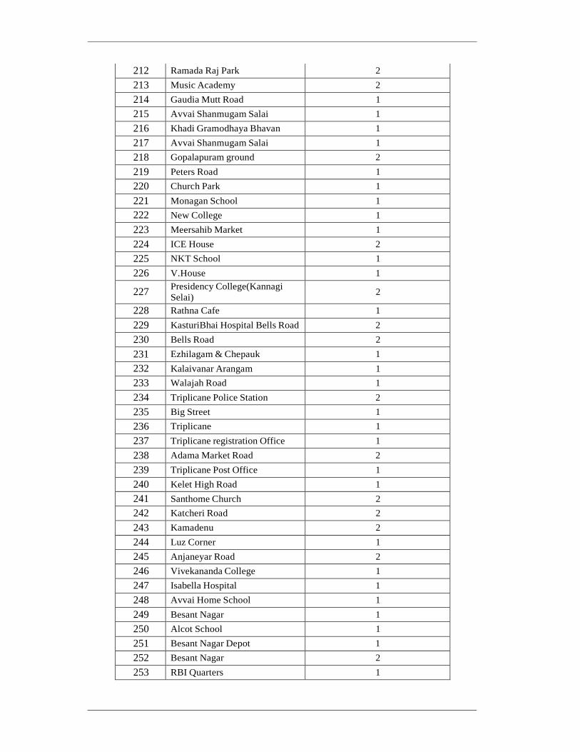
212 Ramada Raj Park 2
213 Music Academy 2
214 Gaudia Mutt Road 1
215 Avvai Shanmugam Salai 1
216 Khadi Gramodhaya Bhavan 1
217 Avvai Shanmugam Salai 1
218 Gopalapuram ground 2
219 Peters Road 1
220 Church Park 1
221 Monagan School 1
222 New College 1
223 Meersahib Market 1
224 ICE House 2
225 NKT School 1
226 V.House 1
227 Presidency College(Kannagi
Selai) 2
228 Rathna Cafe 1
229 KasturiBhai Hospital Bells Road 2
230 Bells Road 2
231 Ezhilagam & Chepauk 1
232 Kalaivanar Arangam 1
233 Walajah Road 1
234 Triplicane Police Station 2
235 Big Street 1
236 Triplicane 1
237 Triplicane registration Office 1
238 Adama Market Road 2
239 Triplicane Post Office 1
240 Kelet High Road 1
241 Santhome Church 2
242 Katcheri Road 2
243 Kamadenu 2
244 Luz Corner 1
245 Anjaneyar Road 2
246 Vivekananda College 1
247 Isabella Hospital 1
248 Avvai Home School 1
249 Besant Nagar 1
250 Alcot School 1
251 Besant Nagar Depot 1
252 Besant Nagar 2
253 RBI Quarters 1

254 Vannathurai 2
255 Indira Nagar Water Tank 3
256 Aranganathan Subway 1
257 Srinivasa Theatre 1
258 Mettupalayam 1
259 Mettupalayam 1
260 RR Colony 2
261 Raghava Colony 1
262 West Saidapet 1
263 Jayaraj Theatre 1
264 Manthoppu School 2
265 Jones Road 1
266 TNHB Flats 1
267 Kamdar Nagar 1
268 Periyar Road 3
269 Vetinary Hospital 1
270 Opp to ONYX 2
271 MGR Salai 1
272 Palm Grove 1
273 Vidyodaya school 2
274 Meenakshi College 3
275 Meenakshi College 1
276 Trustpuram School 2
277 Powerhouse 3
278 Ram theater 3
279 Pachaiyappa College 1
280 New Avadi Road 1
281 Kilpauk Garden 1
282 Water Tank Kilpauk New Avadi
Rd 1
283 VOC Nagar 1
284 Gandhi Nagar Hospital 2
285 Gandhi Nagar 1
286 Nathamuni Talkies 1
287 Bala Vihar 2
288 Chinthamani 2
289 Anna Nagar Roundtana 2
290 Blue Star 2
291 Ayyapan Kovil 2
292 12th Main Road 2
293 Aminjikarai Police Station 1
294 Anna Siddha Hospital 2
295 Vasantham Colony 1

296 Labour Officers Quarters 2
297 Vijaya Maruthi (Anna Nagar) 1
298 South Colony 2
Total 532
4 System Functional Requirement
Table 4-1: Functional requirement of PIS
Sl
No.
Requirements
Real-Time PIS Display Boards
1. PIS shall be used to display information to passengers at selected bus terminalsand busstops.
2. The signs shall support a variety of information displayschemes, including multi-phase messages and the ability to display scrolling text. Related parameters (e.g. Multi-phase Message Transition Time, Display Line Scroll Speed and List Sorted By) shall be configurable.
3. Content can include –Transportation Information (Bus schedules, alerts, etc.), safety information,
localized community information, GPS driven localized data, Environmental data, advertising (still images, animation, video), tourist information.
4. All type of PIS shall have the capacity to store static information in the display controller (including schedules), which shall be shown if the communication link is lost and after real-time information expires.
5. The static information shall be stored in non-volatile memory, with memory capacity at least double that required for the initial data.
6. The total weight of the signs, including all internal and external components, shall be such that it doesn’t cause any structural or any other damage to the structure to which the sign is mounted. Contractors need to assess the existing structure and design the PIS mounting provision.
7. The sign enclosures shall be vandal proof, and the housing shall be black for effective message contrast and legibility.
8. The sign assemblies shall be secured to sustain the shock and vibration that exists in outdoor environment.
9. The signs shall not contain controls accessible to the public.
10 The signs shall be legible when sunlight is shining directly on the display face or when the sun is directly behind the display.
11 PIS software that can upload Tamil and English text as per business and operational needs of the Employer shall be provided.
12 The PIS display board shall be industrial grade that can withstand the environmental and working conditions found at bus bus/shelter and terminals in Chennai. The panels shall allow for 24/7 operations.
13 The signs shall be capable of receiving the following as inputs from the central system, on an as- required basis:
• System management commands (e.g. system status requests)
• Static display information (e.g. bus schedules, hours of operation and bus routes)
• Real-time display information (e.g. current time and time until arrival of next bus(es))
• Ad-hoc information (e.g. traveller warnings, current weather conditions and advertisements)
PIS shall support alphanumeric, video, image, animations and graphics.
14 All types of display board shall provide for modular layout enabling parallel display of content
on different areas of the screen – Transit information, Time/Date, Weather, Public announcements, Commercial advertising.
15 All types of display boards shall have in-built test facility, able to carry out self- check at periodic intervals as well as exchange of diagnostic information from the central control stations including power availability, and its current status.
16 The display system shall support remote settings such as display intensity, time synchronization.
17 PIS display shall be refreshed automatically every 10 seconds to show updated information.

18 When an entire message cannot fit on the PIS, it shall be possible to display the entire message by displaying the message using multiple frames by pagination or scrolling through the messages.
19 The choice of display method will be selectable by the Employer and message scroll speed shall be fully configurable by the Employer.
20 Time for which information is displayed in each language shall be configurable by the Employer.
21 PIS application shall be integrated with Environmental sensor application and display the environmental information on PIS display board.
22 PIS displays shall be managed locally without workstation or server.
23 Contractor shall arrange all the switches, network items and cables, etc. as required.
24 Contractor shall be responsible for arrangement of all communication.
25 The API and Integration document to be provided for to integrate with PIS application and any other application envisaged by MTC.
26 Display boards shall have NTCIP communication protocol. No proprietary protocol is allowed to use.
27 Characters shall be at least 8cm - 12 cm high to allow for a viewing distance up to 15 meters at bus stops/shelters for Type B and Type C LED boards and up to 30 meters viewing distance for the Type A LED display boards.
28 For Type A display boards 3 hours power backup and for Type B and C display boards 1 hour power backup is required.
29 Only outdoor rated UTP CAT6 cable shall be used to connect the device to the respective switch port. If for any case, the distance between the switch port and device exceeds 90 m, use outdoor
rated multi-mode fibre cable with environmentally rugged media converters. 30 The system shall default to display the predicted number of minutes until arrival of the next bus.
Website Requirement
31 Website shall be designed to show the information in Tamil and English language.
32 Website shall allow commuter to plan their bus trip using direct routes and transfers of the city- wide bus system including suburban buses.
33 Information requested by commuter on map line diagram or table shall be updated automatically without manual page refresh.
34 The Contractor shall build the new website pages with the purchaser input (branding, graphics and colours).
35 The Contractor shall be responsible for integration and setup of the website and source code of the website shall be submitted by the Contractor.
36 The Bidder shall provide a Web Server to host the website. SMS
37 Contractor is expected to develop SMS for commuters without a GPRS connection with their mobile. This is to provide ETA, Stop code, fare, pass, route no, etc., through SMS.
38 All the sent and receive SMS information shall be stored in the system to generate report by dispatcher. At least 10,000 SMS shall be considered every month.
39 Contractor requested to provide complete support if any third-party integration id required to integrate SMS for MTC
40 Contractor to develop the SMS system to provide both instant response and preconfigured.
41 Contractor to provide the report with the detail of how many SMS sent from system, how many are received, unique numbers, etc.
42 Contractor has to develop the Mobile application that shall work in at least two major mobile OS platforms. Preferably Android, and iOS platform
43 Contractor is responsible to upload the software to online mobile stores on behalf of MTC Mobile Application
44 The mobile application/website shall have at least following features both in Tamil and English :
Smart card recharge
Vehicle location finder
Real time bus arrival on the selected bus station
Commuter to find the nearest bus station from his/her location along with distance
Display ETA for the selected bus station, buses arrive in next 15 minutes
Find nearest landmark (this will be shared by purchaser)

Provide Fare, Stop name, Stop code, Bus Pass, other major places, feedback,
Provide option for commuter to share the photos taken in case of any problem they found on the bus service limited to project jurisdiction (Chennai)
Feedback/ Grievances
Distance between two stops
Displays stop code and name for the selected route/direction
Notification on the predefined alerts
Identify nearest parking location
Integration with other mode of transport
Source code of the Mobile application shall be submitted by the Contractor.

5 Hardware Requirement
All hardware equipment shall as a minimum, meet all the requirements listed in the specifications. The equipment’s provided shall accommodate to future technological advances which exceeds the minimum requirements provided in the specifications.
5.1 LED display board
Table 5-1: Hardware requirement of LED display board
S. No. Parameter Requirements
1. Color Amber
2. Brightness & Legibility
To be read even in broad daylight without any shade.
The displayed image shall not appear to flicker to the normal human eye.
3. Luminance Class L-3 as per EN 12966
4.
Display capability
Fully programmable, LED displays, Alpha-numeric,
Pictorials, Information on the display shall be refreshed every 10 seconds
5. Information Display Method
Static, Dynamic, Pagination, Right - Left,
6. Display Language Multilingual Tamil and English
7. Display Front Panel 100% anti-glare
8. Auto Dimming Auto dimming sensor adjusts to ambient light level
9.
Display Area
For Type A, clear viewing area Horizontal: 3.00 meters
Vertical: 2.50 meters
For Type B, clear viewing area Horizontal: 1.20 meters
Vertical: 1.00 meters
For Type C, clear viewing area Horizontal: 1.20 meters
Vertical: 0.60 meters
Clear viewing area means excluding frame, brackets, etc.
10. Number of Lines in each type of board
For Type A – 10 lines For Type B – 4 lines For Type C – 2 lines
11. Connectivity Ethernet or GPRS through modem for each display board separately
12. Protocol NTCIP protocol
13. Controller Controller shall have the functionality to turn off the display when not required or non-operational hours.
14. Casing Front: IP-54 for Display of PIS Rear and Side: IP-66 for cabinet
15. Operating conditions 0° to 55°C
16. Pole and Foundation The pole and handing provision shall withstand at least 180 km
wind speed for all type of display boards
17. Earthing and Lighting Arrester
Earthing and Lighting arrestor to be designed and provided

5.2 Power Supply and Outdoor UPS
Table 5-2: Hardware Requirement of Outdoor UPS
No. Item Requirements
1. Input / Output Voltage
■ AC 230 V / 50 Hz basically. ■ Output voltage: AC230V/50Hz
■ Commercial Power generally but with existing condition of power
failure, instantaneous power failure and voltage fluctuation
2 UPS ■ The UPS shall be of True online with double conversion topology. ■ The UPS shall work in outdoor environment to ensure all
equipment’s getting necessary power supply. No power surge.
■ The UPS unit shall have load level indicators that display the approximate electrical load placed upon the UPS. The UPS unit
shall have a row of battery level indicators that display the approximate battery capacity.
■ The UPS unit shall have a minimum of the following as per OEM
standard indicators:
➢ UPS Mode: On-line, Backup/Battery and Bypass; ➢ Over Load Indicator: This will display when UPS is running
on overload;
➢ Battery Status Indicator: This will illuminate when battery is low or faulty/disconnected; and
➢ System Fault: This will illuminate when there is some fault or interruption in UPS.
■ The UPS unit shall include Ethernet communication port to
support remote management and monitoring capabilities using SNMP including alarm contacts and remote shutdown. Remote
monitoring and testing software shall be included. The
manufacturer shall provide all SNMP traps. ■ The UPS unit shall include automatic restart. Upon restoration of
utility AC power after complete battery discharge, the UPS shall automatically restart and resume operation.
■ The UPS unit shall be compliant to IEC 62040-1, CE, IEC602040- 2 safety standards.
■ The UPS and batteries shall be mounted in a separate cabinet & the enclosure shall be under lock & key, utilising the minimum
possible space and arranged in an aesthetic manner.
■ Any field UPS system (as per MSI’s design) shall be supplied with an environmentally rated cabinet for installation of the UPS and
batteries. The cabinet shall have a rating of IP 55. The cabinet shall be supplied with in-built fans and proper ventilation as needed to
ensure that the temperature inside the cabinet does not exceed 40
degrees C at any given point in time.
■ Backup time at least 3 hrs for Type A and 1 hour for Type B & C
5.3 Pole
Table 5-3: Pole Specification
No. Item Specification
1. ■ The PIS shall be installed either on T shape structure. ■ The Contractor shall make all design considerations during design of pole to withstand

wind speeds of at least 180 kmph and shall be designed and approved by the Engineer and following appropriate guidelines.
■ Any cable entering into the PIS board shall be properly protected and should not be visible
outside.
■ PIS Pole shall be hot dip galvanized after fabrication with silver coating of 86 micron as per IS:2629; Fabrication in accordance with IS-2713 (1980)
■ Height of pole shall be minimum 3 meters above the ground.
■ Casting of Civil Foundation with foundation bolts, to ensure vibration free erection ■ The pole shall be equipped with lightning arrester as per the requirements ■ The Structure should have walkway for maintenance staff to easily access and maintain
PIS. ■ The passage from structure to PIS should have locking provisions to avoid any
unauthorized access.
■ A sign board describing words such as “Don’t Touch / This area is under surveillance”
shall be hanged on the pole. The Contractor shall conduct the detailed design for the pole based on his site survey.
■ The Contractor shall conduct the appropriate measure for preventing the vibration which will affect the detection accuracy.
■ All components of poles may be hot dip galvanized, all components must be well protected against corrosion, minimum thickness of zinc coatings is 85 µ m and min
density 500 gm/m 2 on both inside and outside surfaces ■ Certified BS EN 10025-4:2019 – TC ■ Required Lighting arrester arrangement inside the pole.
6 Communication Requirement
Table 6-1: Communication Requirements of PIS
No. Requirements
1. ■ Communication between the PIS server in the CCC and the PIS board at each terminal shall be Wireless Connectivity provided by a single communication company.
■ The required bandwidth to ensure the stable communication connectivity shall be proposed by the Contractor and subsequently approved by the Engineer.
7 Installation Requirement
The Contractor shall make the provision for necessary civil, foundation, earthing, necessary
cable conducting, manhole, Power supply, redundant communication, new meter connection, quality, safety and last mile connectivity etc. to meet the functional requirement intended for the system. The Contractor shall obtain necessary permission from respective agency. At the terminals and bus shelters, LED based passenger information display boards will be installed
with their base at least 10 feet height from the surface level. LED board will be installed on the unipole structure with strong foundation, and with orientation configured with MTC for desired areas where riders will need to view. Pole will be MS material with rust protection coating, and with safety warning stickers as per standard. UPS to be fixed on the cabinet to protect from vandalism.

Chapter 3-4 Requirements of Depot Management System
1 General
(a) Each depot will be equipped with the Depot Management System (DMS) to enable and
manage their effective operation. This software will manage service scheduling, crew
rostering, asset management and maintenance, vehicle fueling/availability, crew
attendance, and business intelligence/reporting.
2 System Configuration
The system configuration of DMS is shown in the figure below.
Figure 2-1: System Configuration of DMS
3 Equipment Location
The proposed locations for DMS are shown below in the Table. The Contractor shall adhere to the proposed locations as much as possible to satisfy the above requirement. In case of any changes in the locations the Contractor shall get the written approval from the Engineer based on the alignment, geometry, viewing area (based on site visit).
Table 3-1: Depot locations
No. Location Type Location Name Latitude Longitude
1 Depot Adambakkam 12.99489 80.20669
2 Depot Adyar 12.998189 80.256461
3 Depot Alandur 12.997006 80.191718
4 Depot Ambattur Industrial Estate 13.099555 80.169956
5 Depot Anna Nagar West 13.093802 80.198147
6 Depot Avadi 13.12138 80.102082
7 Depot Ayanavaram 13.098746 80.241035
8 Depot Ayyapanthangal 13.037233 80.134635

9 Depot Basin Bridge 13.102701 80.273682

No. Location Type Location Name Latitude Longitude
10 Depot Central Depot 13.07584 80.275799
11 Depot Chrompet I 12.947442 80.14092
12 Depot Chrompet II 12.947509 80.144356
13 Depot Ennore 13.215657 80.32077
14 Depot K.K Nagar 13.034841 80.205415
15 Depot Kundrathur 12.980404 80.102187
16 Depot Madhavaram 13.131771 80.236474
17 Depot Mandaveli 13.026362 80.266311
18 Depot Padiyanallur 13.203698 80.174104
19 Depot Perambur 13.102234 80.249026
20 Depot Poonamallee 13.052055 80.090679
21 Depot Saidapet 13.014439 80.225685
22 Depot Tambaram 12.932504 80.121025
23 Depot Theyagaraya Nagar 13.034499 80.230046
24 Depot Thiruvanmiyur 12.986873 80.259291
25 Depot Thiruvottiyur 13.172324 80.304347
26 Depot Tondairpet I 13.131906 80.292436
27 Depot Tondairpet II with Workshop 13.135094 80.290183
28 Depot Vadapalani 13.05047 80.206876
29 Depot Vyasarpadi 13.120182 80.259245
30 Depot Kannagi Nagar 12.925528 80.238407
31 Depot Perumbakkam 12.886605 80.210028
4 System Functional Requirement
Table 4-1: Functional requirement of Depot
Management System
No General Requirements
1. The system shall be able to support operations for a minimum of 6000 buses.
2. Ability to optimize the complete service delivery by developing the route and publish final timetables & rosters.
3. Ability to Generate informative statistical summaries and MIS from the system
4. The software shall provide standard reports based on the DMS data. Bidders shall provide details in their proposal related to reports offered and the degree to which they can be configured (at
minimum all reports shall be configurable for a specified date/time range and routes or schedules
or service type). Summary reports for different levels of management staff shall be designed by Contractor during the design stage. Automated graphs/plots for commonly used data shall be
provided in discussion with the Employer. Following are tentative list, this may be
updated/added during design and implementation period:
• Route Plan & Timetables • Trips & Vehicle Planning • Crew Schedules

• Roster and Dispatch (Operations) • Crew Kiosks (optional) • Performance monitoring • Bus travel time data from CAD/AVL system
5. The application shall provide feature for creating vehicles in one depot and process for transferring vehicles to other depots.
6. Application shall have feature to capture trip/schedule wise revenue kilometre
7. Capability to capture dead kilometres in the System.
8. Ability to define and create Charter trips into the system. Solution shall provide the entire process – Quote, Booking, Allocation, Invoicing, etc
9. The charter trips should be reflected into the operation module for rostering and dispatch functions.
10. Ability to capture requirements from customer for chartered trips into the system.
11. Ability to make quick changes in routes and bus stop locations due to traffic management (traffic police) changes (one-way streets, construction, etc.)
12. Ability to create users in the system
13. Ability to assign roles, access and user permission in the system
14. System should support user defined event definition for sending alerts and message
15. System should be able to send alerts and email based on certain conditions/events/transactions.
16. Ability to produces printouts of crew schedules, duty rosters, route timetables, bus stop timetables etc.
17. Ability to generate On-demand statistical reports and summaries
18. The system shall ability to generate following reports, but not limited to, • Route
• Timetable
• Crew Rostering
• Statistics Report - Headway, Running times for each trips.
• Dispatch report • Schedule cancellation report
• Crew allocation • Schedule allocation
• Crew utilization report
• Fleet departure at depot
• Fleet dead KM per route/ fleet wise
• Revenue kilometre • Schedule or trip cancellation • Crew license renewal history • Overtime details per staff wise
19. The ability to import and export master data such as nodes detail with its respective GIS data to the Map, Crew, Vehicle, Schedule, Routes with stop, etc.
20. System shall provide facility to export data/reports into PDF, Excel, CSV and XML formats
21. Proposed System should be able to perform trip time deviation analysis to find where the critical trips
22. Route Creation and Timetable
Vehicle Scheduling & Dispatching & Crew Rostering
23. System should have ability to edit/specify inbound and/or outbound timetable for a specified day type.
24. Allow user to define the path type for the timetable - circular, loop, Radial etc.
25. Ability to add, edit and copy/duplicate timetables
26. Only authorized user should be able add, edit or delete timetables
27. Ability to link/add trips to the selected timetable.
28. Allow an authorized user to add, edit, delete and copy/duplicate a bus schedule.
29. Ability to link all the inbound and outbound trips in manual, assisted and auto mode.
30. Ability to indicate the number of buses required to operate all of the trips upon complete linking of all the trips.

31. System shall have ability to provide appropriate error messages in case layover times and dead run
timings do not match in the timetables, buses are less, Crew are less, etc. 32. System shall have ability to minimize shifts
33. System shall have ability to minimize layover time at Depots and meal/relief points
34. System shall have ability to suggest minimum vehicles required for the schedule.
35. System shall have ability to maximise or minimise the bus running hours
36. System shall have ability to display exceptions such as trip without any bus
37. System shall have ability to colour code trips
38. System shall have ability to link /unlink buses to trips
39. System shall have ability to perform parallel scheduling of services such as trunk and feeder
system, the schedule of the trunk bus and the feeder bus must be synchronized to the extent possible, to minimize the transfer waiting time for passengers. The system should allow for such synchronization and calculate automatically the trips and schedules of a route/multiple routes
40. System shall have ability to provide multiple MIS and reports from the System, including but not
limited to:
• For timetable
• by path • by route
• by start time
• by end time
• by trip number
• by distance • by speed • bus arrival and departure summary from a depot • Number of buses operating in traffic from a depot and/or division spread over 24 hours
41. The system shall support existing MTC employee rules. The Contractor is expected to study before the bid submission.
42. System shall have ability to create crew schedules considering different shift parameters such as shift spreads, mealtime etc.
43. System shall have ability to create crew scheduling as per the Motor Vehicle Act followed by MTC.
44. System shall have ability to define shift start and end points
45. System shall have ability to minimize travel time from relief points to depot / meal locations
46. System shall have ability to minimize breaks between 2 blocks of service
47. System shall have ability to schedule duties such that the last portion of duty shall close at a particular depot/terminal or specified location defined by MTC
48. System should be capable of creating crew schedules for bus schedules that operate from a specific depot or division.
49. Crew transfer within division
50. Capability to create crew schedule considering a specific meal break location for a particular Route Number / selected route numbers
51. System should be accessible by all Depot authorized users to download the Crew schedules created by the system
52. System shall support following reports but not limited to, a) Detailed Crew report for each duty / crew day(s) of the week clearly indicating Sign On, Sign
Off , Trip details that are to be performed, meal break location, etc.. b) Consolidated Crew report for all duties in a depot for day(s) of the week clearly indicating Sign On, Sign Off , Steering time and hours of duty for driver and conductors
c) Statistics reports of crew and depot.
d) Horizontal Blocks to provide duty wise details of each crew along with the Route number on
which they will perform duty
53. The Bidder shall provide a Crew Rostering Software, already used by Public Transport Operators.
54. The Software shall have provision for creating the Roster as per Rules, Acts and statutory requirements.
55. Crew Rostering module shall be able to create group of users based on set of defined parameters.

56. The proposed rostering module shall plan and generate the rostering automatically for next one month, through to the end of the current financial year, or for the subsequent fiscal year.
57. It shall allow admin or authorized user to create and view the planning for a week/month before applying it to real production.
58. System shall have provisions to easily make changes to the planned roster
59. System shall have provision to create rosters for user definable day types such as Public Holidays, weekends etc.
60. System shall have capability to automatically rotate crew as per the user definable parameters
61. System shall have ability to create groups and types of crew.
62. System shall have ability to assign crew work/duties based on user defined groups
63. System should have provision to include non-driving work in the roster
64. System should have provision to utilise drivers from other Depots
65. The proposed rostering application shall display or provide rostering using graphical representation for the selected period
66. The Rostering module shall interface with scheduling module to assign crews automatically to the schedule.
67. In case schedule is cancelled then rostering shall update crew’s operation hours, ideal hours, etc., for day to improve the operation.
68. Rostering shall have technique to minimize and help MTC in identifying the non- performing/underperforming crew.
69. All schedules shall be identified by schedule number and/or start and destination name.
70. Schedule master shall have minimum start place, end place, starting and end time of each trip, rest time in between the trips, distance between the start and end place, distance between stops, overnight stay, crew name, fleet registration number, etc.
71. Scheduling module shall allow admin or authorized user to update, modify or cancel the schedule.
72. It shall also allow user to cancel a particular trip in the case of a partial schedule cancellation.
73. The proposed application shall allow users to modify/update the schedule quickly.
74. The system shall provide following MIS reports at minimum, but are not limited to (Following are tentative list, this may be updated/added during design and implementation period):
• Distance Reports
• Depot Reports
• Station Reports
• Route Reports
• Form-4 Reports or any other types followed in MTC • Anomalies Reports • Dead Kilometre Reports • Comparative Reports
75. A design document for content and formats for the display board information shall be developed by the Contractor and approval shall be obtained from the Purchaser before implementing the design.
76. Bidder shall provide one Printer cum scanner to each depot to scan A4 and letter size paper.
77. The software shall have the capability to generate reports based on exceptions as per thresholds set by MTC.
78. The Bidder shall provide tools to generate ad-hoc reports on stored CAD/AVL data.
79. All reports must use standard reporting tools similar to Apache Spark, Hadoop, IBM IoT
framework, Microsoft Azure, and have the ability to export data into file formats that can be
exported to and edited with standard office software (e.g., Microsoft Word and Excel, Adobe Acrobat .PDF)
80. Any portion of the transactional database shall be exportable in standard formats (such as .csv, xls,
xlsx, xml, etc.) for analysis in third party programs. 81. A data dictionary shall be provided to MTC to facilitate development of custom reports.
82. All reports shall be generated using a query language and standard query engine (to be approved by MTC) that provides flexibility for future updates, and for creation of new reports.
83. Reporting software shall include the ability to generate graphs and charts based on criteria and format defined by the user

84. The Software shall be capable of establishing automatic periodic (monthly/ quarterly/ yearly) routines to automatically produce and email standard reports to defined user groups.
85. The Software shall provide a web-based reporting tool to allow for access from anywhere. The access and views of the reports will be based on Role based access control.
86. Software shall allow MTC to generate Summary and Detail reports as applicable.
87. The system shall provide following reports at minimum, but are not limited to (Additional reports and Template will be discussed finalized along with MTC during the design stage) :
• Breakdown • Accident • Vehicle In/Out
• Pending Maintenance • KMPL for each Fleet • Vehicle FC, Road permit history • Complete history of each vehicle maintenance by month and year
88. The proposed application shall store employee related master details without any limitation.
89. Attendance shall be recorded using Biometric Readers installed at various places across MTC locations.
90. The system shall not allow any records to be deleted. But it shall allow admin to edit employee personal info, others as required.
91. Access shall be configurable based on location/user-type/user-group.
92. The Super User or Admin shall have access to all data.
93. The Master table will have minimum of Date of birth, Date of Joining, Earlier Service, Experience, Department, Designation, Seniority, Salary, etc.
94. Attendance system shall interface with Depot Management System to provide crew absence.
95. Overtime and festival working renumeration shall be calculated automatically by the System.
96. System shall Maintain leave and holidays as per MTC list or as desired by the Employer time to time.
97. Application shall have provision to request transfer of fleet/bus and crew to other depots or other places.
98. Staff shall be able to check available vacation and sick leave using the system.
99. Application shall support deputation for emergency and required time.
100. System shall be able to save documents like birth certificates, education certificates, license, offer/ appointment order, etc.
101. Admin shall be able to export birth certificates, education certificates, license, offer/ appointment order, etc. from the system in PDF format.
102. The proposed systems shall be interfaced with ITS systems as mentioned in this RFP document.
103. All modules/sub-modules of the Depot Management System shall be seamlessly integrated
104. System shall support deriving efficient vehicle assignment by route through minimizing repositioning and dead runs
105. System shall have integrated Optimization Tool for vehicle and crew based on various constraints and preferences
106. The solution shall have ability to generate “what-if” scenarios.
107. The mobile application shall have at least following minimum features both in Tamil and English:
Mobile app shall show the features as per role defined during design stage.
For crew, fleet Schedule and vehicle details, license renewal, request for leave, attendance
For branch manager, fleet FC renewal, fleet maximum operational years or maximum running kilo meter
Provide option to share the photos taken during incidents
5 Hardware Requirement
5.1 Workstation at Depot for DMS

Table 5-1: Hardware requirement of Workstation at depot for DMS
No Item Requirements
1. CPU Quad core CPU with 8 threads or equivalent or better
2. Memory 8 GB DDR4 or better
3. Hard-Disk Drive 512 GB SSD or better
4. Display One number 21”-inch LCD / LED Display
5. Display ports 4 Display Port / mini–Display Ports Toolkit/Stand to install the dual monitors
6.
GPU
Base clock: 1290 Mhz or better Number of cores: 768 or better VRAM: 4GB or better Display connectors: DP 1.4, HDMI 2.0b, dual link-DVI multi- monitor support Max resolution: 7680 x 4320 @ 60 Hz or better
7. Keyboard Wired keyboard with 104 keys
8. Mouse Wired Optical with USB interface
9. Ports USB Ports including 2 USB 3.0 Ports and audio ports for
microphone and headphone 10. Cabinet Mini Tower.
11. Operating system Windows 10 64-bit operating system
12. Software Tools Microsoft Office 365 or equivalent
13. Antivirus To be provided
5.2 Laser Printer – A4
Table 5-2: Hardware requirement of Laser printer – A4
No Item Requirements
1. Print Speed Black: 16 ppm or A3, 24 ppm or above on A4
2. Resolution 600 X 600 DPI
3. Memory 8 MB or more
4. Paper Size A4, Legal, Letter, Executive, custom sizes
5. Paper Capacity 250 sheets or above on standard input tray, 100 Sheet or above
on Output Tray
6. Duty Cycle 25,000 sheets or better per month
7. OS Support Windows 8, and any latest version
8. Interface Ethernet Interface
9. Other requirement(s) Shall have the ability to Scan, Send and Receive Fax
5.3 Biometric Reader
Table 5-3: Hardware requirement of Biometric reader
No Item Requirements
1. Display LCD display with operating system
2. Reader Type Both Fingerprint and Smart card
3. Memory Internal: 512MB External: 2 GB
4. Application API / Web application
5. Connectivity Ethernet, Wi-Fi, USB

6. Power supply 12v DC and inbuilt battery backup of 2 hours
7. Security certification STQC
8. Storage capacity Two fingers of each staff: 1,000 Smart card: 500 Transaction storage 1,00,000
5.4 UPS at Depot
Table 5-4: Hardware requirement of UPS at depot
No Item Requirements
1 Capacity Adequate capacity to cover all above IT Components at respective location
2 Output Wave Form Pure Sine wave
3 Input Power Factor at Full Load >0.90
4 Input Three Phase 3 Wire for over 100 KVA
5 Input Voltage Range 305-475VAC at Full Load
6 Input Frequency 50Hz +/- 3 Hz
7 Output Voltage 400V AC, Three Phase for over 100 KVA UPS
8 Output Frequency 50Hz+/- 0.5% (Free running); +/- 3% (Sync. Mode)
9 Inverter efficiency >90%
10 Overall AC-AC Efficiency >85%
11 Battery Backup 3 hours in full load with SMF battery
12
Indicators & Metering
Indicators for AC Mains, Load on Battery, Fault, Load
Level, Battery Low Warning, Inverter On, UPS on Bypass, Overload, etc.
13 Cabinet Rack / Tower type
14 Operating Temp 0⁰C to 50⁰C
6 Communication Requirement
Table 6-1: Communication Requirements of DMS
No. Minimum Specifications
1. ■ Communication between the DMS terminal at each depot and the DMS server at CBS CCC shall be wired connectivity provided by a single communication company, if
required MPLS VPN shall be provided.
■ The required bandwidth for DMS to ensure the stable communication connectivity shall
be proposed by the Contractor and subsequently approved by the Engineer.
7 Installation Requirement
The Contractor shall make the provision for necessary civil, foundation, earthing, necessary cable conducting, manhole, Power supply, redundant communication, new meter connection, quality, safety and last mile connectivity etc. to meet the functional requirement intended for the system. The Contractor shall obtain necessary permission from respective agency. A smart card reader (with associated camera to capture image of the person using) will be installed near each entry and exit of the depot to log attendance times within the facility. These devices will be powered by UPS backup to ensure smooth and continuous operation.

Chapter 4 Bill of Quantity (BOQ)
1 Supply of Plant/Equipment and Spare parts
Item
No. Description Unit Qty
(1) (2) (3) (4)
201 Chennai Traffic Information & Management System
Command Control Centre (TIMS-CCC) - -
i Control Centre Room - -
A1 Call Centre Application and Database No 1
A2 IP PABX System with IVR No 1
A3 Operator Client Licenses Lot 1
ii Meeting Room - -
A4 70” LED display Nos 2
A5 Over Head Projector No 1
iii Furniture - -
A6 TIMS Operation Room Operator Desks Lot 1
A7 TIMS Management Room Manager's Desks Lot 1
A8 TIMS Management Room Meeting Table (14-Seater or More)
Lot 1
A9 Call Centre Operator Desks Lot 1
A10 Security Room Desks Lot 1
A11 Help Desk Team Desks Lot 1
A12 Technical Support Team Desks Lot 1
A13 Meeting Room Furniture (10-Seater or More) Lot 1
A14 High Back Executive Chair Lot 1
iv Building Utilities - -
A15
Interior works including fall ceiling, utility duct, Accessories as per requirement (Power Switch Boards, PVC
Conduits, Power and Network cables, etc) (Approx. 7500 Sq. Ft)
Lot
1
A16 Access Control System Nos 4
A17 Fire & Smoke Detection System Lot 1
A18 Lighting Lot 1
A19 DG Set for TIMS Control Centre with 72 hours backup No 1
A20 Air-condition for TIMS Control Centre Lot 1
A21 UPS Parallel Redundant with Battery backup of 3 hours Lot 1
A22 CCTV surveillance at TIMS Control Centre Nos 4
A23 PA system for building Lot 1
A24 Wi-Fi accessible across control centre Lot 1
A25 Provision for Sanitization Lot 1
v Hardware Components - -
Hardware Components for Data Centre - -
A26 Network Racks Lot 1
A27 Server Racks Lot 1
A28 Servers- (As per System Design) Lot 1

Item
No. Description Unit Qty
(1) (2) (3) (4)
A29 Internet Server Lot 1
A30 Load Balancer Lot 1
A31 Firewall with IPS Lot 1
A32 Data Storage Lot 1
A33 SAN Switch Lot 1
A34 L3 Switch (Copper or/and OFC) Lot 1
A35 LEVEL 2 Switch (24 Port) Lot 1
A36 LEVEL 2 Switch (48 Port) Lot 1
A37 Web Application Firewall (WAF) Appliance with DDOS Protection
Lot 1
A38 Tape Drive Nos 1
A39 Cartridge Magazine Lot 1
Hardware components for Control Centre - -
A40 Video Wall Panel, with Controller, 70" Nos 48
A41 Video Wall Switcher No 1
A42 Multi-Function Laser Printer – Colour A3, A4 (TIMC Management Room)
Nos 2
A43 Operator Workstations -3 Monitor (TIMC Management Room)
Nos 16
A44 Manager Workstation (TIMC Management Room) No 1
A45 Help Desk Team Workstations Nos 2
A46 Technical Support Team Workstations Nos 4
A47 Call Centre Workstations Nos 4
A48 Security Room Workstations Nos 2
A49 Meeting/Situation Room Workstation No 1
A50 IP Phones Nos 36
A51 Call Recording Device No 1
Software Components at Data Center - -
A52 Video wall management Software Lot 1
A53 Virtualization Software Lot 1
A54 Centralized Antivirus Software Lot 1
A55 Access Control System Software Lot 1
A56 Backup software Lot 1
A57 CAL, OS, database licence Lot 1
vi Network Bandwidth - -
TIMS Network Backbone - -
A58 Redundant Bandwidth Cost (For Edge Equipment) Lot 1
A59 Primary Internet Bandwidth (For TIMS to CBS Data Center)
Lot 1
A60 Primary Internet Bandwidth (For TIMS to DR) Lot 1
A61 Secondary Internet Bandwidth (For TIMS to CBS Data Center)
Lot 1
A62 Secondary Internet Bandwidth (For TIMS to DR) Lot 1
vii ITMS
A63 ITMS (Application Software) Lot 1

Item
No. Description Unit Qty
(1) (2) (3) (4)
A64 EMS Application No 1
A65 Website No 1
A66 Mobile Application (Android & iOS) No 1
viii Mandatory Spare Parts
A67 L3 Switch (Copper /OFC) Nos 1
A68 LEVEL 2 Switch (24 Port) Nos 1
A69 LEVEL 2 Switch (48 Port) Nos 1
A70 SAN-SW Nos 1
A71 IP Phones Nos 2
A72 Call Recording Device Nos 1
ix Other Items - -
A73 Other Items to make system functional and meet SLA Lot 1
202 Adaptive Traffic Signal Control System (ATCS) - -
i Controller with accessories - -
B1 Signal Controller Nos 165
B2 Controller Cabinet Nos 165
ii Detector - -
B3 Vehicle Detector Nos 570
iii Mounting - -
B4 Standard Poles Nos 716
B5 Cantilever Poles Nos 567
iv Aspects & Activation Buttons - -
B6 Vehicular Aspect - Red Ball Nos 1158
B7 Vehicular Aspect - Amber Ball Nos 1158
B8 Vehicular Aspect - Green Ball / Straight Nos 953
B9 Vehicular Aspect - Green Arrow Left Nos 814
B10 Vehicular Aspect - Green Arrow Right Nos 839
B11 Vehicular Aspect - Red Arrow Right Nos 260
B12 Vehicular Aspect - Amber Arrow Right Nos 260
B13 Pedestrian Aspects – Walk Nos 1154
B14 Pedestrian Aspects - Flashing Don’t Walk With Timer Nos 1154
B15 Pedestrian - Push Button Nos 1154
B16 Pedestrian Buzzer Nos 1154
B17 Green U- turn aspect Nos 57
V Software - -
B18 ATCS Application Lot 1
vi Connectivity - -
B19 Network Equipment with accessories Nos 165
vii Power Requirements - -
B20 Outdoor UPS with batteries for 3-hour backup for field elements
Nos 165
viii Mandatory Spare Parts - -
B21 Standard Poles Nos 46

Item
No. Description Unit Qty
(1) (2) (3) (4)
B22 Cantilever Poles Nos 34
B23 Signal Controller Nos 10
B24 Controller Cabinet No 10
B25 Vehicle Detector Nos 34
B26 Vehicular Aspect - Red Ball Nos 70
B27 Vehicular Aspect - Amber Ball Nos 70
B28 Vehicular Aspect - Green Ball / Straight Nos 58
B29 Vehicular Aspect - Green Arrow Left Nos 50
B30 Vehicular Aspect - Green Arrow Right Nos 50
B31 Vehicular Aspect - Red Arrow Right Nos 16
B32 Vehicular Aspect - Amber Arrow Right Nos 16
B33 Pedestrian Aspects – Walk Nos 70
B34 Pedestrian Aspects - Flashing Don’t Walk with Timer Nos 70
B35 Pedestrian - Push Button Nos 70
B36 Pedestrian Buzzer Nos 70
B37 Green U - turn aspect Nos 5
B38 Network Equipment with accessories Nos 3
B39 Outdoor UPS with batteries for 3-hour backup for field elements
Nos 8
Ix Other items - -
B40 Other items to make system functional and meet the SLA Lot 1
203 Traffic Incident Detection System (TIDS) - -
i Equipment - -
C1 TIDS (Application Software) Lot 1
C2 TID Camera Nos 63
C3 PTZ Camera Nos 58
C4 Controller Nos 58
C5 Network Equipment with accessories Nos 58
C6 UPS for 3-hour backup with Batteries and Outdoor junction Box
Nos 58
ii Material - -
C7 Cabinet Nos 58
C8 Standard Pole Nos 52
C9 Cantilever Pole Nos 6
iii Mandatory Spare Parts - -
C10 Cabinet Nos 3
C11 Standard Pole Nos 3
C12 Cantilever Pole Nos 1
C13 TID Camera Nos 4
C14 PTZ Camera Nos 3
C15 TIDS Cameras Controller Nos 3
C16 Network Equipment with accessories Nos 3

Item
No. Description Unit Qty
(1) (2) (3) (4)
C17 UPS for 3-hour backup with Batteries and Outdoor junction Box
Nos 3
iv Other items - -
C18 Other items to make system functional and meet the SLA Lot 1
204 Variable Message Sign System (VMS) - -
i Equipment - -
D1 VMS System (Application Software) Lot 1
D2 VMS Board with controller and necessary accessories Nos 17
D3 Network Equipment with accessories Nos 17
D4 UPS for 3- hours backup with Batteries and Outdoor junction Box
Nos 17
ii Material - -
D5 Cabinet Nos 17
D6 Gantry Nos 17
iii Mandatory Spare Parts - -
D7 VMS Board with controller and necessary accessories No 1
D8 Network Equipment with accessories No 1
D9 UPS for 3- hours backup with Batteries and Outdoor junction Box
No 1
iv Other items - -
D10 Other items to make system functional and meet the SLA Lot 1
205 Speed Limit Violation Detection System (SLVD) - -
i Equipment - -
E1 SLVD (Application Software) Lot 1
E2 Doppler Radar and ANPR Camera Nos 11
E3 IR Illuminator/Flash for SLVD Nos 11
E4 Local Software for SLVD Nos 11
E5 LPU for SLVD Nos 11
E6 Speed Display Board (Radar based) Nos 11
E7 Network Equipment with accessories Nos 11
E8 UPS for 3-hours backup with Batteries and Outdoor junction Box
Nos 11
ii Material - -
E9 Cabinet Nos 11
E10 Standard Pole Nos 11
iii Mandatory Spare parts - -
E11 Cabinet Nos 1
E12 Standard Pole Nos 1
E13 Doppler Radar and ANPR Nos 2
E14 IR Illuminator for SLVD Nos. 2
E15 LPU for SLVD No 1
E16 Speed display (Radar based) No 1
E17 Network Equipment with accessories No 1

Item
No. Description Unit Qty
(1) (2) (3) (4)
E18 UPS for 3 -hours backup with Batteries and Outdoor junction Box
No 1
iv Other items - -
E19 Other items to make system functional and meet the SLA Lot 1
F Red Light Violation Detection System (RLVD) - -
i Equipment - -
F1 RLVD System (Application Software) Lot 1
F2 ANPR Camera (One per lane) Nos 439
F3 IR Illuminator for ANPR Nos 439
F4 RLVD Camera Nos 165
F5 Local Software for ANPR Nos 439
F6 Local Software for RLVD Nos 165
F7 LPU for RLVD & ANPR Nos 165
F8 Network Equipment with accessories Nos 50
F9 UPS for 3h backup with Batteries and Outdoor junction Box Nos 50
ii Material - -
F10 Cabinet Nos 50
F11 Gantry (U-Type) Nos 135
F12 Cantilever Pole (L-Type) Nos 30
iii Mandatory Spare Parts - -
F13 Cabinet Nos 3
F14 Gantry (U-Type) Nos 1
F15 Cantilever Pole (L-Type) Nos 2
F16 ANPR Camera (One per lane) Nos 23
F17 IR Illuminator for ANPR Nos 23
F18 RLVD Camera Nos 12
F19 LPU for RLVD & ANPR Nos 12
F20 Network Equipment with accessories Nos 3
F21 UPS for 3- hours backup with Batteries and Outdoor junction Box
Nos 3
iv Other items - -
F22 Other items to make system functional and meet the SLA Lot 1
G Automatic Traffic Cum- Counter (ATCC) - -
i Equipment - -
G1 ATCC1 System (Application Software) Lot 1
G2 ATCC2 System (Application Software) Lot 1
G3 Image Recognition Detector Nos 230
G4 Processing Unit Nos 230
G5 Network Equipment with accessories Nos 230
G6 UPS for 3- hours backup with Batteries and Outdoor junction Box
Nos 230
ii Material - -

Item
No. Description Unit Qty
(1) (2) (3) (4)
G7 Cantilever Pole with Dual Arm Nos 54
G8 Cantilever Pole with Single Arm Nos 117
G9 Cabinet Nos 171
iii Mandatory Spare Parts - -
G10 Cantilever Pole with Dual Arm Nos 3
G11 Cantilever Pole with Single Arm Nos 6
G12 Cabinet Nos 6
G13 Image Recognition Detector Nos 12
G14 Processing Unit Nos 12
G15 Network Equipment Nos 12
G16 UPS for 3h backup with Batteries and Outdoor junction Box Nos 12
iv Other items - -
G17 Other items to make system functional and meet the SLA Lot 1
208 Computer Aided Dispatch/ Automatic Vehicle Location
System (CAD/AVL) - -
i CAD/AVL Software
H1 CAD/AVL Central Application Lot 1
H2 EMS Application Lot 1
ii CAD/AVL Hardware - -
H3 Onboard ITS Device (SCU & BDC) Nos 2940
H4 SIM Cards Nos 2940
H5 Cable Between onboard ITS device and CANBus Port Nos 2940
H6 Workstation at Depot - with 21" dual monitor Nos 31
H7 UPS for 3 hours backup with Batteries Nos 31
iii CAD/AVL Mandatory Spare Parts - -
H8 Onboard ITS Device (SCU&BDC) Nos 147
H9 Workstation at Depot - with 21" dual monitor Nos 2
H10 UPS for 3 hours backup with Batteries Nos 2
iv Other items - -
H11 Other items to make system functional and meet the SLA Lot 1
209 Passenger Information System (PIS)
i PIS Software - -
I1 PIS Software with ETA/ETD calculation No 1
I2 Commuter Website No 1
I3 Commuter SMS System No 1
I4 Commuter Mobile Application (Android & iOS) No 1
ii PIS Hardware - -
I5 Type A - PIS - LED boards at Terminals Nos 20
I6 Type B - PIS - LED 4 Line boards Nos 96
I7 Type C - PIS - LED 2 Line boards Nos 500
I8 Pole Nos 20

Item
No. Description Unit Qty
(1) (2) (3) (4)
I9 SIM Cards Nos 616
I10 UPS for 3 hours backup with Batteries and Outdoor junction Box
Nos 20
I11 UPS for 1 hour backup for 4-line and 2-line boards with Batteries and Outdoor junction Box
No 596
iii PIS Mandatory Spare Parts - -
I12 Type A - PIS - LED boards at Terminals No 1
I13 UPS for 3 hours backup with Batteries and Outdoor junction Box
Nos 1
I14 Type B - PIS - LED 4 Line boards Nos 5
I15 Type C - PIS - LED 2 Line boards Nos 20
I16 UPS for 1 hour backup for 4-line and 2-line boards with Batteries and Outdoor junction Box
Nos 25
iv Other items - -
I17 Other items to make system functional and meet the SLA Lot 1
210 Depot Management System (DMS)
i DMS Software - -
J1 Vehicle Planning and Scheduling No 1
J2 Vehicle Dispatch and Crew Rostering No 1
J3 Attendance Management System No 1
J4 MTC Staff Mobile Application (Android & iOS) No 1
ii DMS Hardware - -
J5 Workstation at Depot - with 21" single monitor Nos 31
J6 Printer Laser – A4 Nos 31
J7 Biometric Reader Nos 62
J8 UPS with 3 hours backup for DMS Workstation & Printer Nos 31
iii Mandatory Spare Parts - -
J9 Biometric Reader Nos 4
J10 Workstation at Depot - with 21" single monitor Nos 2
J11 UPS with 3 hours backup for DMS Workstation & Printer Nos 2
iv Other items - -
J11 Other items to make system functional and meet the SLA Lot 1
211 CBS Command Control Centre - -
i Control Centre Room - -
K1 IP PABX/EPABX System including 2 - PRI lines No 1
K2 Land Line Phone (IP phone Video Phones) Nos 14
ii Meeting Room - -
K3 70” LED display No 1
iii Furniture - -
K4 Control centre Table and Chair as per the proposed layout Lot 1
iv Building Utilities - -
K5 Fire & Smoke Detection System Lot 1
K6 Lighting Lot 1

Item
No. Description Unit Qty
(1) (2) (3) (4)
K7 DG Set CBS (ITS equipment Load Only) 72 hours backup No 1
K8 100% parallel redundant UPS with 3 hours backup Lot 1
K9 CCTV surveillance at CBS Control Centre Nos 4
K10 Wi-Fi accessible at control Center Lot 1
K11 Provision for Sanitization Lot 1
K12
Interior works including fall ceiling, utility duct, Accessories as per requirement (Power Switch Boards, PVC Conduits, Power and Network cables, etc) (Approx. 2500 Sq. Ft)
Lot
1
v Hardware Components - -
K13 Network Racks Lot 1
K14 Server Racks Lot 1
K15 Servers (AVL, PIS & DMS) Lot 1
K16 Internet Server No 1
K17 Load Balancer No 1
K18 Firewall with IPS Nos 2
K19 Data Storage Lot 1
K20 SAN Switch No 1
K21 L3 Switch (Copper + OFC) Nos 2
K22 LEVEL 2 Switch (48 Port) Nos 2
K23 Web Application Firewall (WAF) Appliance + DDOS Protection
No 1
K24 Tape Drive No 1
K25 Cartridge Magazine Lot 1
vi Hardware components for Control Centre - -
K26 Video Wall Panel, with Controller, 70" (3x3) No 1
K27 Video Wall Switcher No 1
K28 Network LaserJet Printer - A3 & A4 paper No 1
K29 All in One Printer (Colour Print, Copy, FAX) No 1
K30 Workstation for CAD/AVL & PIS with 21" dual Monitor Nos 22
K31 Technical Support Team Laptop Nos 4
vii Software Components at Data Centre - -
K32 Video wall management Software Lot 1
K33 Virtualization Software Lot 1
K34 Centralized Antivirus Software Lot 1
K35 Backup software Lot 1
K36 CAL, OS, database licence as per design Lot 1
viii Network Bandwidth - -
CBS Network Backbone - -
K37 Primary Connectivity (Mpls or Leased line) Lot 1
K38 Secondary Connectivity (Mpls or Leased line) Lot 1
ix Mandatory Spare Parts
K39 L3 Switch (Copper + OFC) Nos 1
K40 LEVEL 2 Switch (48 Port) Nos 1

Item
No. Description Unit Qty
(1) (2) (3) (4)
K41 SAN-SW Nos 1
K42 Land Line Phone (IP phone Video Phones) Nos 1
K43 Hands free/Headphone for dispatchers Nos 1
x Other Items - -
K44 Other Items to make system functional and meet SLA Lot 1
2 On site Installation, Training and Testing
Item
No.
Description Unit Qty
301 Chennai Traffic Information & Management System Command
Control Centre (TIMS-CCC) -
-
A1 Installation to meet functional requirement Location 1
A2 Test and Commissioning Location 1
A3 Training Lot 1
A4 Safety measures items Lot 1
A5 Other items to make system functional and meet SLA Lot 1
302 Adaptive Traffic Control System (ATCS) - -
B1 Installation including power supply, cabling and wiring,
grounding/earthing, protection against lightning, cabinet/junction box,
support structure, radio interference, road signs and markings and
necessary civil works etc to meet the functional requirement
Location
165
B2 Test and Commissioning Location 165
B3 Training Lot 1
B4 Safety measures items Lot 1
B5 Other items to make system functional and meet SLA Lot 1
303 Traffic Incident Detection System (TIDS) - -
C1 Installation including power supply, cabling and wiring,
grounding/earthing, protection against lightning, cabinet/junction box,
support structure, radio interference, road signs and markings and
necessary civil works etc to meet the functional requirement
Location
58
C2 Test and Commissioning Location 58
C3 Training Lot 1
C4 Safety measures items Lot 1
C5 Other items to make system functional and meet SLA Lot 1
304 Variable Message Sign System (VMS) - -
D1 Installation including power supply, cabling and wiring,
grounding/earthing, protection against lightning, cabinet/junction box,
support structure, radio interference, road signs and markings and
necessary civil works etc to meet the functional requirement
Location
17
D2 Test and Commissioning Location 17
D3 Training Lot 1
D4 Safety measures items Lot 1

Item
No.
Description Unit Qty
D5 Other items to make system functional and meet SLA Lot 1
305 Speed Limit Violation Detection System (SLVD) - -
E1 Installation including power supply, cabling and wiring,
grounding/earthing, protection against lightning, cabinet/junction box,
support structure, radio interference, road signs and markings and
necessary civil works etc to meet the functional requirement
Location
11
E2 Test and Commissioning Location 11
E3 Training Lot 1
E4 Safety measures items Lot 1
E5 Other items to make system functional and meet SLA Lot 1
306 Red Light Violation Detection System (RLVD) - -
F1 Installation including power supply, cabling and wiring,
grounding/earthing, protection against lightning, cabinet/junction box,
support structure, radio interference, road signs and markings and
necessary civil works etc to meet the functional requirement
Location
50
F2 Test and Commissioning Location 50
F3 Training Lot 1
F4 Safety measures items Lot 1
F5 Other items to make system functional and meet SLA Lot 1
307 Automatic Traffic Cum-Classifier (ATCC) - -
G1 Installation including power supply, cabling and wiring,
grounding/earthing, protection against lightning, cabinet/junction box,
support structure, radio interference, road signs and markings and
necessary civil works etc to meet the functional requirement
Location
171
G2 Test and Commissioning Location 171
G3 Training Lot 1
G4 Safety measures items Lot 1
G5 Other items to make system functional and meet SLA Lot 1
308 Computer Aided Dispatch/ Automatic Vehicle Location System
(CAD/AVL) - -
H1 Installation including cabling and wiring, etc to meet functional
requirement Bus 2940
H2 Test and Commissioning Bus 2940
H3 Training Lot 1
H4 Safety measures items Lot 1
H5 Other items to make system functional and meet SLA Lot 1
309 Passenger Information System (PIS) - -
I1 Installation including power supply, cabling and wiring,
grounding/earthing, protection against lightning, cabinet/junction box,
support structure, radio interference, road signs and markings and
necessary civil works etc to meet the functional requirement
Location
616
I2 Test and Commissioning Location 616
I3 Training Lot 1
I4 Safety measures items Lot 1

Item
No.
Description Unit Qty
I5 Other items to make system functional and meet SLA Lot 1
310 Depot Management System (DMS) - -
J1 Installation including to meet functional requirement Location 31
J2 Test and Commissioning Location 31
J3 Training Lot 1
J4 Safety measures items Lot 1
J5 Other items to make system functional and meet SLA Lot 1
311 CBS Command Control Centre - -
K1 Installation to meet functional requirement Location 1
K2 Test and Commissioning Location 1
K3 Training Lot 1
K4 Safety measures items Lot 1
K5 Other items to make system functional and meet SLA Lot 1

Chapter 5 Drawings
Refer the drawings provided as separate volume
1) Part 2 – Employers requirements –
Section VII. Technical Requirements
Drawing for references – Vol 1
2) Part 2 – Employers requirements –
Section VII. Technical Requirements
Drawing for references – Vol 2

Section VIII Operation and Maintenance
Requirements
1 Introduction
Operation and Maintenance of CITS Project shall be executed in the manner originally intended, that is to collect and analyze the traffic and bus operations data into useful information, disseminate the information to road users and public transport commuters in accordance with the procedures as set forth herein and instructions given by the Engineer and Employer time to time during the Project period. The system shall be in operation for 24 hours a day and 7 days a week without interruption. The Contractor shall not divert and modify the procedure without written approval by the Employer, and Engineer.
The purpose of Operation and Maintenance of system is to keep the traffic information and management system (TIMS) and city bus system (CBS) and related facilities in operation in the manner originally intended, that is to collect and analyze the traffic and bus operations data into useful information, disseminate the information to road users and public transport
commuters and to prolong the life of the system and the equipment. Therefore, time is of essence. Repair must be done in a timely manner.
The specifications described herein shall be considered the minimum standards to be followed for the maintenance and repair of all equipment’s, facilities, tools etc covered under the Contract. Unless otherwise specified, the standards for equipment and equipment performance shall be in accordance with the Technical Specification of Employer’s Requirements
2 Scope of Works
Apart from installation of scope delivered by the Contractor also includes Operation and
Maintenance, Manpower, Spare parts inventory for a period of 60 Months from the date of completion of trail run and acceptance which includes 24 Months of Defects Notification Period.
Except otherwise specified in the Operation & Maintenance Specifications of Employer’s Requirements, it is the Contractor's responsibility to provide sufficient manpower to implement flawless execution of CITS Project and related systems under this Contract in operation in the manner originally intended, that is to collect road, traffic data to process and analyses useful information, disseminate the information to road users and undertake the Services that are not specifically mentioned in these requirements but essential for the safe and efficient traffic operation on the Chennai ITS under this contract.
The Contractor shall maintain qualified staff at the Command-and-Control Center with require necessary, tools, shop facilities, equipment, consumables, transportation and materials and perform all works necessary to maintain in good working manner of system and associated equipment under this contract.
2.1 Operation and Maintenance service Proposal
The Contractor shall describe the methodology and outline to execute proposed Services both Operation & Maintenance in sufficient detail in his Services Proposal to enable the Employer to evaluate the technical capability and qualification of the Contractor and to judge whether the proposal is adequately responsive or not.
The Contractor shall update and furnish the Service Proposal two (2) months before expected

starting date of Operation period for approval by The Engineer and Employer.
The Services Proposal shall describe the operation and maintenance activities taking
Manufacturer or OEM recommendations for all hardware and software into consideration and shall be written in the same sequence as the Employer’s Requirement. Where the supporting documents such as brochure, article, report, or paper are provided, they shall be attached at the end of the proposal or in a separate volume and a cross reference shall be prepared. The Services Proposal shall be written in English.
This plan shall be updated as necessary during the O&M period so as to reflect the actual conditions of O&M

The Operation and Maintenance proposal also includes the Manpower deployment schedule in accordance with the requirement defined in this document.
2.2 Main requirement for Operation & Maintenance service
Main requirement for Operation & Maintenance service but not limited are; Operation & Maintenance of the system under this contract
Emergency Response and recovery of the system
Periodic Inspection, Preventive Maintenance, and Corrective Maintenance
Upgrading software
SLA Monitoring and Management
Call Center & another day-to-day operation
Spare parts management
Training
Helpdesk services
Any other as necessary or desired in order to maintain the SLA
2.3 Sub-system for Operation & Maintenance service
Operation & Maintenance services are required to cover the following sub-system;
Two Command and Control Center one for TIMS and another for CBS at the respective
Locations. Traffic Information and Management System (TIMS)
Adaptive Traffic Signal System (ATCS)
Traffic Incident Detection System (TIDS)
Red Light Violation Detection System (RLVD)
Speed Limit Violation Detection System (SLVD)
Variable Message Sign (VMS)
Automatic Traffic Counter and Classifier (ATCC)
Command Control Center (TIMS-CCC)
City Bus System (CBS) Automatic Vehicle location System (AVL)
Passenger Information System (PIS)
Depo Management System (DMS)
Command Control Centre (CBS-CCC)
Others Network monitoring and Management
Power Supply and Management
hardware and software, and other related facilities, tools, equipment’s and infrastructure etc.
installed as part of the CITS project during the Contract Period.
Any other items covered under this contract during the project period
3 General Requirement
The specifications described herein shall be considered the minimum standards to be followed for the maintenance and repair of all equipment and software covered under the Contract. Unless otherwise specified, the standards for equipment and equipment performance shall be
in accordance with the Technical Specification.
3.1 The Contractor’s Personnel

3.1.1 Key Personnel
For the purpose of discharging its obligations under the Contract, the Contractor shall recruit and
deploy the specified number of key personnel, non-Key staff, full time or intermittent of suitable qualification and experience as described in this document. The Contractor shall ensure that the key personnel deployed are of good health, of highest integrity, punctual, well dressed, well behaved and of qualification and experience prescribed in the Employer requirement table given in this document. The CV submitted for the key staff will be considered for evaluation of the Contractor capability.
Frequent replacement of key personnel is not desirable unless they are found involved in malpractices or non-compliances. However, a permission of replacement of key personnel shall be obtained from the Engineer in advance together with the request for approval of replacement. The Engineer, if satisfied with the reasons submitted to him, may allow such
replacement after verifying the CVs strictly in accordance with the requirements.
The Indicative List of Personnel given in Section VI. General Requirement. however, the
Contractor shall mobilize the requisite additional personnel according to the site condition during the Project Period with a written request to the Engineer and Employer and subsequent approval.
3.1.2 Non- Key Personnel
For the purpose of discharging its obligations under the Contract, the Contractor shall recruit and deploy the specified number of Non- key personnel of suitable qualification and experience. The Contractor shall ensure that the key personnel deployed are of good health, of the highest integrity, punctual, well dressed, well behaved, and of qualification and experience prescribed hereunder.
The frequent replacement of Non- key personnel is not desirable unless they are found
involved in malpractices or non-compliances. However, the permission of replacement of Non- key personnel shall be obtained from the Engineer in advance together with the request for approval of replacement. The Engineer, if satisfied with the reasons submitted to him, may allow such replacement after verifying the CVs strictly in accordance with the requirements and better than original.
The Indicative List of Personnel given in the table below however, the Contractor shall mobilize the requisite additional personnel according to the site condition during the Project Period with a written request to the Engineer and Employer and subsequent approval.
3.1.3 Deployment of Personnel
The Contractor shall recruit and deploy suitable personnel as outlined in this document during the operation and maintenance in the Employer Requirement. The manpower shown is minimum in number of Key Personal and Non-Key personal having fulltime and intermittent inputs along with Field Support Engineers and staffs, however the Contractor shall deploy additional manpower in order keep the Operation and Maintenance services as intended in the Employer Requirement.
The Contractor shall furnish to the Employer and Engineer, in addition to the list of key personnel provided with the tender, a list of persons deployed for the purpose of discharging
its obligations under the Contract, containing all the details like their educational qualifications, experience, training undergone, and recent photograph.

The Employer reserves its right to object to the deployment of any personnel for any reason. In such case, the person or persons being objected to by the Employer shall be removed by
the Contractor forthwith and replace.
The Employer shall not be liable for any misconduct or misdeeds or any act or incident involving the Contractor or any of its personnel in any criminal or civil case. The Contractor shall be responsible for consequences and if any such incident takes place, the Contractor shall forthwith intimate the said incident to the Employer.

The Contractor shall employ Project Director, Project Managers and the suitable number of operators. The temporary number of these staff and the tasks assigned to them estimated by Employer is shown in this RFP. It shall be noted that the number indicated in the table is the minimum requirements by Employer and it is the Contractor’s responsibility to provide high quality service seamlessly and effective staff arrangement shall be recruited if necessary. International Staff shall carry out the technology transfer as an important aspect including CITS Project technology through operation and maintenance works to Employer and
Contractor’s local staffs.
The staff member shown in this RFP is the persons directly engaged in the CITS Project
Operation and Maintenance Services and the Contractor shall recruit and deploy the necessary number of managers, operators and technicians.
The Contractor shall provide all personnel necessary for performing the CITS Project operation and maintenance by the personnel listed in Table. The Contractor shall submit curriculum vitae of the candidate non- key person for the Engineer’s approval two (2) months in advance of the start of operation and maintenance work. These engineers shall be involved in the installation, adjustment, test on completion and training of the Stakeholder Organisation staff of the CITS Project to be supplied under the Contract.
The Contractor shall submit the list of all CITS Project Operation and maintenance staff with name, birth date and address together with copy of ID every month to the Engineer. If there is any change in the composition of the operation and maintenance staff, it shall be reported immediately to the Employer. The Employer will issue an ID to each staff member. The Contractor shall be responsible for the proper use of the ID to gain the access to the access-controlled places and system facilities and return it immediately if a staff member no longer works for the CITS Project Operation and maintenance.
During O&M period, The Contractor shall submit the system generated attendance record of each employee deployed at the locations with each service invoice. The Engineer shall have the access to the logs of biometric attendance management system for verification of the actual manpower working days in a month. The amount against manpower will be payable only for the duration the O&M personnel will be available at site. In case the required manpower is not available at any location for more than 15 days in a month, no payment shall be made against manpower (as quoted in the financial bid) for that location for whole month, apart from other
deductions / penalties as applicable.
3.1.4 Penalty for delay in Manpower Mobilisation - Delay in submission of detailed written statements and/or mobilization of aforesaid Key
Personnel shall attract penalty @ INR 1,00,000/- (Rupees One Lacs) per day per Key Personnel
- In case the delay is more than 3 weeks, the Employer reserves the right to encash the
Performance Security towards the aforesaid penalty and may proceed with termination of the project, as the case may be.
3.1.5 Penalty for Replacement of Manpower The Manpower proposed shall be dedicated to the project and shall not be proposed for any other
project or assigned any other project. The resource cannot be changed for at least two years.
In case of any variation or change in the manpower/person proposed in the Technical Proposal and manpower/person deployed upon successful award of the works, minimum of 20% remuneration of the proposed role for the total contract period shall be deducted.

The substitute proposed by the Contractor must propose for equivalent or better than the proposed candidate in all respect (no. of years of relevant experience, no. of similar projects executed, qualification of the replacement candidate, etc.).

The Maximum replacement 20% of Key staff and Non-key staff shall be allowed during the Project Period under normal circumstances. If the situation beyond the control of the Contractor, the necessary approval must be taken by the Contractor from the Engineer/Employer.
3.1.6 Working Shift
Two-shift (+1 backup person) system shall be adopted for TIMS and CBS operation. The tentative shift is as shown below.
■ First shift: 05:45 -14:00 hours
■ Second shift: 13:45 - 22:00 hours
3.1.7 Welfare of Contractor's Employee
The Contractor shall be solely responsible and liable for complying with statutory liability for welfare of the employees such as ESI, EPF, workmen’s compensation, wages, bonus medical leave, etc. However, if considered necessary, the Employer shall have every right to enquire and seek documentary evidence from the Contractor to confirm, whether all the statutory dues like ESI, EPF, minimum wages, weekly offs, bonus, medical leave, workman compensation and any
other entitlements, in accordance with the statutory dues applicable in the area are being paid.
3.2 Safety, Security and Protection of Environment
Throughout the period of Contract, the Contractor shall have full regard for safety of all persons
entitled to be upon the CCC area and for the avoidance of danger to such persons specially from moving traffic. All staff employed by the Contractor shall receive the training on the work area safety before assigned to the position. The Contractor shall provide all necessary safety equipment such as reflective vests, hard hats, etc to the persons.
3.3 Employer's Equipment and Property
3.3.1 Provision of Equipment and Property
In order to enable the Contractor to discharge its duties of TIMS Operation and Maintenance Services and CBS Operation and Maintenance Services efficiently and uninterruptedly, the
Employer shall provide such infrastructural facilities including Traffic Information and Management System hardware and software as may be considered appropriate by the Employer and CBS System by MTC.
3.3.2 Care of Equipment
The Contractor shall use the Employer's equipment and property that the Contractor is
allowed to use with utmost care and attention. If the equipment or property under custody of the Contractor becomes inoperative or defective due to the inappropriate operation or use of them by the Contractor's staff, the Contractor shall repair or replace them at his own cost after obtaining the instruction from the Employer as to the remedial measure to be taken. If any liability or obligation with regard to the repair or replacement of Employer's equipment and property is remained unfulfilled by the Contractor at the time of return upon termination of the Contract, the amount necessary for the repair or replacement shall be detected to the payment due to the Contractor. All consumables including but not limited to the printer paper and printer toner shall be arranged and purchased by the Contractor at his own cost.

3.3.3 Power supply and Communication
The Contractor shall make necessary arrangements for provision of power supply at all field
locations, server room and CCC. The Contractor shall make necessary arrangements for provision of Communication at all field locations, server room, CCC, DC, DR, Exchange Information etc..
The Contractor shall perform all the necessary application procedures to the Power Company
required for the power to be supplied to the Chennai Traffic Information & Management
System Command

Control Centre (TIMS-CCC), City Bus System Command Control Centre (CBS-CCC), and all the field equipment’s. All the expenses charged by Power Companies regarding such applications shall be borne by the Contractor. The Contractor shall make all necessary arrangements for to the electricity needed for smooth Operation and maintenance of CITS Project for the entire period of the Contract.
The fixed charges, installation charges, recurring charges, electricity bill, maintenance etc. for each field equipment, TIMS-CCC, CBS-CCC, Contractor’s site office, or any other facility being used by the Contractor under the scope of this Contract shall be in the scope of the Contractor only for the entire Contract period i.e. Design phase, procurement, installation, testing, trail-run, commissioning, operations and maintenance period. The Employer shall not responsible
for any provision for power supply during implementation as well as operations and maintenance period. last mile connectivity work shall be completed before start of the operation and Maintenance services for CITS Project during the project period.
3.4 Inspection and Evaluation
3.4.1 Inspection
The Employer reserves the right to conduct inspection of the Contractor's work at any time without
prior notice, to check, observe, and witness the activities of the Contractor at CCC.
The Contractor shall permit the Employer’s Representative at any time or times during the execution of the Contract to enter upon any place where the Contractor is allowed to access within the Employer's premises for the purpose of inspection or for any other legitimate purpose. The Contractor shall give all required information and inspection of records to the Engineer regarding the operation of the Traffic Information and Management System, if asked for. The purpose of the inspection is to monitor the Contractor's activities and to ensure that all the activities required under the Contract are being carried out properly by the personnel deployed by the Contractor. The Employer may exercise any check control to ensure discharge of various obligations by the Contractor under the Contract including but not limited to following:
1. Adherence to operation procedure stipulated in the operation manuals; 2. Promptness and responsiveness to Emergency call;
3. Promptness and adequateness to communicate with other organizations;
4. Handling of the system and equipment; 5. Adequateness and promptness of VMS message;
6. Adequateness of record keeping;
7. Cleanness and tidiness of the CCC and the rooms that are used by the Contractor's staff; 8. Traffic safety awareness; and
9. Any other check or control as considered
3.4.2 Evaluation by Employer
The Employer will conduct from time to time the evaluation of the TIMS & CBS Operation and Maintenance Service provided by the Contractor under the Contract based on the performance of service level parameters specified in Service level Table.
4 Operation Requirements
The various type of operation related services to be performed by the Contractor shall include the following:
4.1 Standard Operating Procedures

The CITS system is designed and implemented to be up and running for 24 X 7opertions, therefore the staffs are required to be placed in shifts as required. The shift would be varying personnel depending on peak and non-peak traffic pattern and based on requirement from the authorities on weekends and weekdays respectively.

The daily operational activity carries out concerning both Command Control Center (TIMS & CBS). For successful operation and maintenance, Contractor shall define the in minimum standard procedure in consultation of Engineer/Employer but not limited.
Jurisdiction of the TIMS/CBS with maps
Organization structure and reporting relationships
Hours of operation, shift details, staff deployment during various shifts
Emergency and other contact numbers
Details regarding capturing log of various operational activities
Responsibilities of various agencies
The role description of various positions
Coordination mechanism with various agencies
Facility and building management aspects such as utilities, services, etc.
Procedures for notifications
Data backup and archival policies
Asset custody and maintenance related procedures
Access control mechanism
Data and asset security
Communication with Media
Communication infrastructure
Procedure for bypassing any policy requirements
Handling visitors
Office Administration
Training requirements
Other TIMS/CBS manuals
Call Centre detail Operation procedure
Reporting and review of performance metrics
Reporting Application Availability of Average loading time of transaction and Average report
loading
Security testing for Vulnerability assessment
Any other function as desired by the Employer time to time
The Sop’s shall be evaluated from time to time with the Employer as well as the Engineer and
inline needs to be updated for better operation and performance. Contractor shall conduct periodic training or indeed
4.2 TIMS Operation
The TIMS Operation shall be executed in accordance with the procedures as set forth herein and instructions given by the Chennai Traffic Police (CTP). The system shall be in operation for 24 hours a day and 7 days a week without interruption. The Contractor shall not divert and modify the procedure without written approval by the CTP.
4.2.1 Briefing at shift change
Shift time of operators shall be arranged in such a way that there will be an overlapping period of at least 15 minutes. During the overlapped period, new operation team shall be briefed or shall
review the status and notes shared by the previous operation team as to the following: General traffic condition
Weather condition
Existing incidents and accident being disposed of
On-going and scheduled works in the City
On-going and scheduled events in the City and major roads along with critical junctions
Messages being displayed on VMS
Equipment malfunctioned and the status of maintenance work
Other matters that need attention of the operation team

4.2.2 Confirmation of equipment condition
At the start of a shift, operators shall confirm the condition of all equipment through operation or through the consoles. If there is a new failure that was not reported by the previous shift team, the operator shall record it and report it to the maintenance team for proper maintenance action. During the operation of the system, if the operator detects any abnormality of the equipment,
software, or database, he shall report it to the maintenance team for proper maintenance action. The operator shall refrain from manipulating equipment, modifying operating parameters, reloading software, or other action without instruction by the maintenance staff when abnormal or defective behavior of the equipment or software is found. If the fault signal or no diagnosis signal response from roadside equipment is received at CCC, operator shall contact the maintenance team and report the location and status of equipment with failure.
4.2.3 Operation of ATCS
Monitor the operation of traffic signals and take suitable interventions as per the traffic situation and incidents and as required, such as change in signal plan, change of signal timing to reduce the congestion from TIMS-CCC enabling green corridor, Plan for Traffic Diversions, or any others measures to improve the traffic flow etc. Periodic change of signal plans and other configurations parameters on directions of Authority (CTP) including following operation.
Planning of Traffic Movement
Design of timing plans
Operation and Management of Traffic Signals
Review and support to the Employer by the Contractor on Signaling Operations
System Audit and Fine Tuning of ATCS parameters
Monitor health of traffic signal equipment and initiate immediate corrective action in any of any fault.
4.2.4 Operation of Incident Management and Traffic Information
Dissemination
(1) Manual Incident Management
When the Operator receives the information from the Help desk and relevant agencies on lane closure, accident, fallen object, construction work, stalled vehicle, pavement problem, adverse weather, fire nearby, etc, Operator shall review the information and generate and resist incidents
manually. All alerts, incidents shall be acknowledged, and corresponding responsive action shall be undertaken as per the type of incident.
(2) Automatic Incident Management
When Operator receives the incident information (heavy congestion and traffic incident detected by TIDS) automatically, the Operator shall review the incidents generated by the TIDS system or related sub-system. All alerts, incidents shall be acknowledged, and corresponding responsive action shall be undertaken as per the type of incident.
(3) Other Incident
Any other incident as defined by the Employer time to time
4.2.5 Operation of RLVD & SLVD
The operator shall review the violations reported by RLVD & SLVD systems and forward them authentic violations to the concerned enforcement officer for the outcome.
Process e-challans for the violation captured by RLVD & SLVD, including generation, verification, and data availability of e-challans.

Track specified vehicles (stolen vehicles or vehicles involved in crimes) based on RLVD/SLVD data.

4.2.6 Operation of VMS
Operators shall exercise utmost care while posting/updating the appropriate messages and images specifically in the selection of messages/words depicted to the road users. The operator shall ensure removal of messages posted after the restoration to normal traffic condition The operator shall disseminate messages on VMS related to.
Cautionary Messages
o Incidents Status o Traffic Condition in the downstream location
Informatory Messages
o Travel Time Messages
o Safety Messages Operator shall manage the message function on VMS related to.
Create message management
o Compose message combination
o Select readily available message and modify o Create display image
Priority management
o Link area management
o Seriousness of incidents and the distance
4.2.7 Operation of ATCC and Review of Traffic Situation
The operator shall ensure the collection of data goes unhindered; the threshold values that are used to detect abnormal traffic conditions shall be reviewed from time to time to confirm that the values are appropriate. The traffic counts and classification provided by ATCC will have to be compared with manual traffic surveys for sample durations to the calculation of accuracy.
4.2.8 Data analysis and sharing
All the system data collected shall be analyzed in a effective way to achieve the project goals
and betterment of the city. The data shall be available is the required format for sharing with
any other stakeholder agency in the required format.
4.2.9 Set up a Call Centre for public help
Call center for communication, emergency information, transportation requirement with public and other team and communication for information sharing and exchange with relative stake holders
4.3 CBS Operation
The public transport buses for Chennai city is managed and operated by Metropolitan
Transport Corporation. Currently, the operations team of MTC manages its fleet of around 3500 buses operated from 31 depots and 9 regions. As part of this project, the City Bus System is being procured for supporting effective operations and provide reliable real-time information to commuters. City Buses operate from 5 AM to 11 PM daily. Currently, each of the regions is managing the daily routine operational activities covering two operational shifts. The CBS operations shall be managed by the Employer’s team. The Contractor shall ensure the availability of the corresponding systems and software. The Contractor’s personnel shall support the operations conducted by Employer’s personnel. The Contractor’s Key Personnel for CBS shall review the operations and shall provide inputs on the improvements to be

undertaken and also recommend the best practices to be followed.
The expected daily operations for CBS areas by Employer but supported by Contractor are outlined below.
Vehicle Planning
o Ensuring availability of Buses for operations
o Allocation of Buses for operations

Scheduling
o Operational Bus Schedules/Trips o Assignment of Buses to Schedule / Trips o Assignment of Crew to Buses
Dispatch of Buses from Depots
Monitoring of Bus operations – schedule/trip adherence, skipping stops, early departures, bunching of buses, disruptions, etc
Manage dispatch of buses as per demand
Review of Passenger Information dissemination through website, helpdesk, etc
Reporting and review of performance metrics
5 Maintenance Requirements
The various type of maintenance and repair works and related services to be performed by the Contractor shall include the following:
Preventive Maintenance of all sub-systems
Ensuring uptime and connectivity of the field equipment
Review and reporting of any issues on the connectivity of field equipment
Repair of faulty and breakdown equipment
Management of warranties and AMCs of all hardware
Review of hardware performance and necessary corrective maintenance action for the upkeep
of the same
Management of software/firmware updates and patches for all subsystems and hardware
5.1 General Requirement for Maintenance
5.1.1 Inspection of Faulty Parts
The Contractor shall inspect the faulty part retrieved from the equipment repaired and prepare and submit a report describing the nature of the failure to the Engineer together with his opinion whether the failure is caused by defect, inadequate operation, act by the third party, normal wear and tear or other reasons.
(1) Malfunction (Fault) Report and Work Order
Each corrective maintenance and accident repair work shall be documented on the Malfunction (Fault) Report form and work order form by the Contractor. The Contractor shall prepare and submit the form together with the list of inspection items for the approval of the Engineer. A copy of completed work order forms shall be submitted with the Monthly Progress Report. No payment shall be made without submitting the completed work order forms in Quarterly progress report and quarterly Invoice. The Fault Reports shall be kept in a logbook and shall be made available to the Engineer upon request at any time.
(2) Maintenance and repair records
The Contractor shall maintain a comprehensive record of all maintenance and repair activities and spare parts consumptions and inventory. The records shall include minimum maintenance checklists, fault reports, spare parts receiving and consumption records, and work orders. These records shall be kept in a database and various operations including but not limited to search and retrieval of fault record by specified key, statistical processing of records into performance index, and calculation of MTBF, MTTR, and other parameters shall be possible.
5.1.2 Maintenance Facilities
(1) Maintenance Equipment and Tools
The Contractor shall maintain the required set of maintenance equipment and tool, and

monitoring and testing software normally required for the maintenance of the electrical and server system. The maintenance equipment and tools shall be maintained in good working condition so that they shall be available all the time. If periodical calibration is required, it shall be calibrated at the regular interval as specified by the supplier of the maintenance equipment. The maintenance staff shall be trained as to the

use of the maintenance equipment and tools. The purchase or depreciation cost of the maintenance equipment and tools shall be deemed to be included in the appropriate cost item in the bid and no separate payment shall be made.
(2) Operation/Maintenance room/space
The Employer will provide the allocated space for operation and maintenance purposes in
Command- and-Control Center at both the locations at CTP & MTC to the Contractor. The Contractor shall observe the regulations regarding the use of the maintenance office. Only persons authorized by the Engineer shall be allowed to use the office and the office shall be used solely for the operation & maintenance of the TIMS and CBS. The Contractor shall prepare at his cost desks, chairs, shelves, cabinets, telephone, Internet access, and other furniture and facilities necessary for the efficient operation & maintenance.
(3) Maintenance Office
The Contractor shall prepare and maintain Maintenance Office in Chennai at their own cost.
The Contractor shall prepare at his cost all running costs of power and telephone/internet,
desks, chairs, shelves, cabinets, and other furniture and facilities necessary for the efficient
maintenance operation.
(4) Maintenance Vehicle
The Contractor shall provide a suitable number of vehicles for their operation & maintenance use. The vehicle shall be of the type suitable for maintenance work in terms of the number of staff/ engineers and load-carrying capacity. The vehicle shall meet the relevant government regulations and be managed by the Contractor. The vehicles shall be maintained in good condition to run across the project locations. The vehicle shall clearly indicate a maintenance vehicle on the side of the vehicle and a yellow flashing light shall be provided on the roof of the vehicle. A set of traffic safety devices consisting of safety cones, stand-alone flashing light, and reflective guide and warning signs shall be provided to the maintenance vehicle. The cost of obtaining, operating, and maintaining the maintenance vehicle shall be included in the contract and no separate payment shall be made.
(5) Spare Parts and Consumable
The Contractor shall maintain required spare parts to maintain required service levels. An undertaking to be submitted along with technical bid that the Contractor has the sufficient infrastructure and capability to keep / store spares required for maintenances and will at all times
during the contract period maintain sufficient inventory of spares and consumables for operating and maintaining the TIMS and CBS and to meet the Service Level requirements.
The inventory of spare parts shall be maintained during the project period. The mandatory spare parts shall be maintained as specified in Chapter 4 Bill of Quantity and will be audited time to time during the project period and any shortfall in this will be subject to penalty as per
one hundred twenty percent (120%) of the unit price quoted in the price bid by the bidder during the project period on quarterly basis. This inventory of mandatory spare parts shall be handed over to the Employer by the Contractor after performance certificate issued by Engineer.
5.2 Preventive Maintenance
The Contractor shall perform the preventive maintenance of all equipment and software
supplied under the Contract in accordance with the preventive maintenance schedule to be

developed by the Contractor and approved by the Engineer.
5.2.1 Inspection Item for Preventive Maintenance
The Contractor shall prepare and submit to the Engineer a list of inspection items for all preventive maintenance work under the Contract two (2) months before the expected starting
date of the O&M period. The inspection item list shall indicate the type of inspection to be performed daily/weekly, monthly, bi-annually, and annually. The inspection item shall cover all the equipment to be supplied under the Contract.

5.2.2 Schedule for Preventive Maintenance
The Contractor shall prepare and submit to the Employer a schedule for all preventive maintenance work under the Contract two (2) months before the expected starting date of the O&M period.
The schedule shall be in sufficient detail to indicate which part of the monthly inspections is to be performed each week and which part of the bi-annual and annual inspections is to be performed each month and the number of maintenance engineers and technicians to be assigned to the work. The Contractor will be required to revise the schedule if the workload and the manpower assignment are unbalanced or unrealistic. Failure to submit an acceptable schedule within the specified time shall be a sufficient cause for suspension of the Contract and/or withholding of payments due to the Contractor.
5.2.3 Check List
The Contractor shall develop and prepare checklists to be used for preventive maintenance for each type of equipment and software and submit them for the Engineer for his approval. The checklists shall include the type of equipment, equipment ID, serial number, location, date of inspection, name of the inspector, check item, and remarks.
The checklist shall be used every time a periodical inspection of the equipment is made, and the results of the inspection shall be recorded together with other details.
The Contractor is required to submit a copy of all recorded checklists every month and as
requested by the Engineer at any time. Failure to maintain or submit the checklists shall be a sufficient cause for suspension of the Contract and/or withholding of payments due to the Contractor.
5.2.4 Software Preventive Maintenance
The Contractor shall perform preventive maintenance of the software to be provided under the Contract as part of the maintenance work. The Contractor shall exert the utmost care not to inadvertently damage the software and database and cause erroneous or abnormal operation of the system.
The items for software maintenance shall include but not be limited to the following: Monitoring of CPU, memory, and disk space utilization
Monitoring of system availability over TCP/IP
Monitoring of anti-virus and system security software operation
Backup of the system and restoration of the system when necessary.
Monitoring and review of system and event logs.
5.2.5 System modification and update
The work to be done consists of modifying the system, system parameter, and other operating conditions and improving the operation or conforming to new operational requirements. The work shall be done as directed by the Engineer. No additional Cost to be paid by the Employer during the project period under this contract.
5.3 Corrective Maintenance and Accident Repair
The Contractor shall provide corrective maintenance and accident repair. Upon reception of a failure/damage notice by the contact person, the Contractor shall log the notice and determine the nature and severity of the failure/damage, prepare the repair plan and dispatch the maintenance crew to the site. Immediate action shall be taken to safeguard the public at any time if the failure

is of nature that causes the hazardous condition.
If the fault cannot be permanently repaired immediately, a temporary repair or remedial measure sufficient to safeguard the operation of the system shall be affected by the Contractor
and the Employer shall be so notified. The Contractor shall assess the extent of the damage, prepare the remedial plan.
5.3.1 Resolution Time and Penalty

The purpose of Service Level Requirement (SLR) is to define the required levels of service provided by the Contractor to the Employer for the duration of the contract.
The benefits of this are: ■ Help the Employer to control the levels and performance of Contractor services:
■ Create clear requirements for measurement of the performance of the system and help in monitoring the same during the Contract duration.
■ The Service Levels Requirement are identified according to Service Level Agreement (SLA) between the Employer and the Contractor.
SLA shall become the part of the Contract between the Employer and the Contractor. SLA
defines the terms of Contractor responsibility in ensuring the timely delivery of the deliverables
and the correctness of the deliverables based on the agreed performance indicators as detailed
in this section.
Service level means the service delivery criteria established for the services specified in Service Level Table. The purpose of Service Levels specified in the Service Levels Tables is to clearly define the levels of service which shall be provided by the Contractor to Employer during O&M period i.e. Five Years from the date of go live of CITS System. The service level parameters mentioned in the service level table shall be measured on a quarterly basis as per the individual service level parameter requirements, through appropriate service level measurement tool of Enterprise Management System (EMS) and Network Management System (NMS). Measurement of service levels for systems shall be automatic using reports
from appropriate management tool of EMS. Measurement of service levels for services, which are not delivered using a dedicated tool, will be carried out using appropriate and relevant reports from the Service Desk tool.
The Contractor would be penalized for non-compliance in meeting Service Level Requirement (SLR). Any penalty levied by Employer or Employer’s representative shall be applicable and deducted from the quarterly payable amount. The Contractor should enable and facilitate continuous measurement of all-round performance of the CITS Project System and not just
event-based performance.
The maximum penalty applicable on quarterly applicable payment for not adhering to the SLA's is capped at 25% of the quarterly applicable payment proposed by the Contractor. However, the Employer along with CTP and MTC has an option to consider termination of the contract if the penalty exceeds 20% of the quarterly applicable payment for any two quarter in four consecutive quarters to the Contractor.
The Contractor shall comply with the SLAs to ensure adherence to project timelines, quality and availability of services throughout the duration of the Contract. For the purpose of the SLA,
definitions and terms as specified in the document along with the following terms shall have the meanings set forth below:
Measurement of Service Level parameters will be carried out on a cumulative basis in a quarter. The Contractor needs to try to ensure that the service levels as per the service level table. The Contractor needs to submit a service level report in a quarter.
If the performance of the system/services is degraded significantly at any given point in time during the contract and if the immediate measures are not implemented and issues are not rectified to the complete satisfaction of the Employer, then Employer will have the right to take appropriate corrective actions including termination of the Agreement.
The Contractor and Employer shall regularly review the performance of the services being

provided by the Contractor and the effectiveness of this Service Levels. The Contractor is responsible for the development and implementation of appropriate management tools of EMS. Which shall be the basis for all project reviews.

The Exhibit below provides the Service Level Agreement (SLA) to be adhered to by the Contractor during the operational hours of the project/system/sub-system/components. In case of non-adherence of the SLR, the corresponding penalties as defined in the Exhibits below shall apply:
5.3.2 Requirement of Resolution Time from Damaged/Failure situation
In case, System and facility is damaged and failure for operation, Contractor is required to resolve the system and facility as soon as possible. For all cases, the failure shall be classified into three severity levels, Critical, Major and Minor. The Contractor shall satisfy the resolution time specified for each type of failure as presented hereunder.
Figure 5-1: Requirement of resolution time
Severity
of Incidents
Definitions Resolution
Time
Falls
By
Penalty
(INR)
Definition Calculation
Incidents 2 5,000/ "Resolution time with For every which have hours “Critical severity level " is Increase of 2 high defined as: time taken to repair hours in time- possibility of the to-repair per immediately device/equipment/application/ instance, a impairing shall be <6 hours and every penalty of road user’s increase of 2 hours penalty INR. 5,000 safety. will be calculated shall be
Critical The impact on <6 hours imposed. the
monitoring /
control of the
system and
information
provision to
public will be
larger.
Incidents 4 5,000 "Resolution time with “Major For every which may hours severity level " is defined as: Increase of 4 impair road time taken to repair the hours in time- user’s safety. device/equipment/application/ to-repair per The impact on shall be <12 hours and every instance, a the increase of 4 hours penalty penalty of
Major monitoring / <12 hours will be calculated INR. 5,000 control of the shall be system and imposed. information
provision to
public is
partial.
Failures of control system that does not have any possibility to impair road users’ safety.
8 50,000 "Resolution time with “Minor For every hours severity level " is defined as: Increase of 8 time taken to repair the hours in time- device/equipment/application/ to-repair per
Minor <24 hours shall be <24 hours and every
increase of 8 hours penalty instance, a penalty of
will be calculated INR. 50,000 shall be

The impact on monitoring
imposed.

Severity of Incidents
Definitions Resolution
Time
Falls
By
Penalty
(INR)
Definition Calculation
/ control of the system
and information
provision to
public is
small in
nature.
1. “Resolution Time” – Time elapsed from the moment incident is reported to the Helpdesk either manually or automatically through system, to the time by which the incident is resolved and services as per the Contract are restored. If complete resolution is not possible in short time, temporally resolution is also considered for recovery from damage and failure.
Category case of Severity Category case of Severity for each component is shown from Table 5.3 to 5.14 in 5.3.4 Requirement of Availability of each component.
5.3.3 Requirement of Repair Time for bug or accuracy fix
Following incident is not so critical to be solved, but to be improved or repaired shortly within few days.,
Table 5-1: Requirement of Repair time for system
bugs and Accuracy fix
No Component Repair time
Falls By
Penalty (INR)
Definition Calculation
1 Application/Software Minor bug fixes
< 7 days 1 day 20,000 "Application/Software
Minor bug fixes" is defined as time taken to fix bus so
that no effect on normal operations occur
For every increase of
1 day in time to fix the bug per instance,
a penalty of INR.
20,000 shall be
imposed. 2 Application/Software < 3day 1 day 50,000 "Application/Software For every increase of
Major Software bugs - Major Software bugs - 1 day in restoring Previous version Previous version previous version per restoration restoration" is defined as instance, a penalty of restoration of the previous INR. 50,000 shall be version of the software imposed. within 1 calendar day so
that application
functionality is restored.
3 Application/Software < 30 days 1 day 50,000 "Application/Software For every increase of Major Software bugs - Major Software bugs - 1 day in version Release new version Release new version" is release with bug fix, defined as Release new per instance, a version of penalty of INR. application/software within 50,000 shall be 30 calendar days with the imposed. fix of the major software
bug

4 Data Accuracy Fix < 7 days 1 day 20,000 "Data Accuracy Fix" is defined as time taken to fix data accuracy as per the functional and technical
For every increase of 1 day in time-to- repair per instance, a penalty of INR.

No Component Repair time
Falls By
Penalty (INR)
Definition Calculation
specifications as defined in the bidding documents.
5,000 shall be imposed.
Major bug ; possible to cause a Critical or Major severity
situation. Minor bug ; not possible to cause a Critical or Major
severity situation.
5.3.4 Requirement of Availability of each component
“Availability “means. When the system is working properly performing all business and
functional requirements as defined in this RFP. The Contractor shall comply with the SLA to ensure adherence to project timelines, quality and availability of services throughout the duration of the Contract. For the purpose of the SLA, definitions and terms as specified in the document along with the following terms shall have the meanings set forth for availability calculation below:
Availability (%) = [1- {(Total Downtime) / (Total Time - Permissive downtime)}] *100.
■ “Total Time” – Total number of hours in consideration for evaluation of SLA performance. ■ “Downtime” – Time period for which the specified services/components/system are not available
in the concerned period, being considered for evaluation of SLA
■ “Availability” as Requirement – Required Time period (%) for which the specified services are available in the period being considered for evaluation of SLA.
■ “Permissive down time” – It includes the time period required for Scheduled Maintenance, repair
works for damages caused by the third parties (e.g. traffic accidents, surge caused by thunder storm, fire, vandalism, etc.), Force Majeure, reasons beyond the control of the Contractor and works as
instructed by the Employer ■ “Scheduled Maintenance Time” – Time period for which the specified
services/components/system with specified technical and service standards are not available due to scheduled maintenance activity. The scheduled maintenance shall be carried out during non-peak hours and shall not exceed more than six (6) hours and not more than four (4) times in a year
■ “Total Down Time” – Any event/abnormalities in the service/system being provided that may lead to
disruption in regular/normal operations and services to the end user.
The below table covers typical incidents which would act as a guideline. If it is left for the
Contractor to decide, they can propose the severities reasonable for severity.

Table 5-2: Availability of ATCS
No Component Severity Level
Requirement Falls By percent
Penalty (INR)
Definition Calculation
1 ATCS Controller Availability
Critical 99.5% 0.5% 5,000 “Controller Availability” is defined as: (1)
device availability, (2) data availability at control center, and (3) proper functioning of the controller and all its related components as per the functional and technical
specifications as defined in the bidding documents.
For every decrease of 0.50% in
performance of each device, its
associated component in a quarter, penalty of INR. 5000 shall be imposed.
2 Detector
Availability
Major 99.0% 0.5% 500 “Detector Availability” is defined as device
availability and proper functioning of the detector and all its related components as per
the functional and technical specifications as defined in the bidding documents.
For every decrease of 0.50% in
performance of each device, its associated component in a quarter,
penalty of INR. 500 shall be imposed.
3 Signal aspect
Availability
Critical 99.0 % 0.5% 100 “Signal aspect Availability” is defined as
device availability and proper functioning of the aspect and all its related components as
per the functional and technical specifications
as defined in the bidding documents.
For every decrease of 0.50% in
performance of each device, its
associated component in a quarter, penalty of INR. 100 shall be imposed.
4 ATCS Application Availability
Critical 99.5% 0.5% 50,000 "ATCS Application Availability” is defined as
the proper functioning of the ATCS Central application and database as per the functional
& technical specifications defined in the bidding documents; this shall also include
software license validity of any COTS,
Database, Software, Anti-virus etc. which is part of the system to achieve operational requirements.
For every decrease of 0.50% in
performance for a quarter, a penalty of INR. 50,000 shall be imposed.

Table 5-3: Availability of TIDS
No Component Severity Level
Require ment
Falls By percent
Penalty (INR)
Definition Calculation
1 TIDS Availability Major 99.0% 0.5% 5,000 “TIDS Availability” is defined as: (1) device
availability, (2) data availability at control center, and (3) proper functioning of the controller and all its related components as per
the functional and technical specifications as defined in the bidding documents.
For every decrease of 0.50% in performance of each device & its
associated component in a quarter, a
penalty
2 TIDS Application Availability
Critical 99.5% 0.5% 50,000 "TIDS Application Availability” is defined as the proper functioning of the TIDS Central
application and database as per the functional &
technical specifications defined in the bidding documents; this shall also include software
license validity of any COTS, Database, Software, Anti-virus etc. which is part of the system.
For every decrease of 0.50% in performance for a quarter, a penalty of
INR. 50,000 shall be imposed.
Table 5-4: Availability of RLVD
No Component Severity Level
Require ment
Falls By percent
Penalty (INR)
Definition Calculation
1 RLVD Availability Major 99.0% 0.5% 5,000 “RLVD Availability” is defined as: (1) device
availability, (2) data availability at control center, and (3) proper functioning of the RLVD devices and all its related components as per
the functional and technical specifications as defined in the bidding documents.
For every decrease of 0.50% in
performance of each device & its
associated component in a quarter, a penalty of INR. 5000 shall be imposed.
2 RLVD Application Availability
Critical 99.5% 0.5% 50,000 "RLVD Application Availability” is defined as the proper functioning of the RLVD application
and database as per the functional & technical specifications defined in the bidding documents;
For every decrease of 0.50% in performance for a quarter, a penalty of
INR. 50,000 shall be imposed.

No Component Severity
Level
Require
ment
Falls By
percent
Penalty
(INR)
Definition Calculation
this shall also include software license validity of any COTS, Database, Software, Anti-virus etc. which is part of the system to achieve operational acceptance.
Table 5-5: Availability of SLVD
No Component Severity Level
Require ment
Falls By percent
Penalty (INR)
Definition Calculation
1 SLVD Availability Major 99.0% 0.5% 5,000 “SLVD Availability” is defined as: (1) device
availability, (2) data availability at control center, and (3) proper functioning of the controller and all its related components as per
the functional and technical specifications as defined in the bidding documents.
For every decrease of 0.50% in performance of each device & its
associated component in a quarter, a
penalty of INR. 5000 shall be imposed.
2 SLVD Application
Availability
Critical 99.5% 0.5% 50,000 "SLVD Application Availability” is defined as
the proper
functioning of the SLVD application and database as per the functional & technical
specifications defined in the bidding documents;
this shall also include software license validity of any COTS, Database, Software, Anti-virus etc. which is part of the system.
For every decrease of 0.50% in
performance for a quarter, a penalty of
INR. 50,000 shall be imposed.
Table 5-6: Availability of VMS
No Component Severity Level
Require ment
Falls By percent
Penalty (INR)
Definition Calculation
1 VMS Availability Major 99.0% 0.5% 5,000 “VMS Availability” is defined as: (1) device
availability, (2) data availability at control center, and
(3) proper functioning of VMS/controller and all
its related components as per the functional and
For every decrease of 0.50% in performance of each device & its
associated component in a quarter, a

No Component Severity
Level
Require
ment
Falls By
percent
Penalty
(INR)
Definition Calculation
technical specifications as defined in the bidding documents.
penalty of INR. 5000 shall be imposed.
2 VMS Application Availability
Critical 99.5% 0.5% 50,000 "VMS Application Availability” is defined as the proper
functioning of the SLVD application and database as per the functional & technical specifications defined
in the bidding documents; this shall also include software license validity of any COTS, Database, Software, Anti-virus etc. which is part of the system.
For every decrease of 0.50% in performance for a quarter, a penalty
of INR. 50,000 shall be imposed.
Table 5-7: Availability of ATCC
No Component Severity Level
Require ment
Falls By percent
Penalty (INR)
Definition Calculation
1 ATCC Availability Major 99.0% 0.5% 5,000 “ATCC Availability” is defined as: (1)
device availability, (2) data availability at control center, and (3) proper functioning of the controller and all its related components as per the functional and technical
specifications as defined in the bidding documents.
For every decrease of 0.50% in performance of each device & its associated component in
a quarter, a penalty of INR. 5000 shall be
imposed.
2 ATCC Application
Availability
Critical 99.5% 0.5% 50,000 "ATCC Application Availability” is defined as the proper functioning of the ATCC Central application and database as per the functional & technical specifications defined in the bidding documents; this shall also include software license validity of any COTS, Database, Software, Anti-virus etc. which is part of the system.
For every decrease of 0.50% in performance
for a quarter, a penalty of INR. 50,000 shall be imposed.

Table 5-8: Availability of ITMS Platform
No Component Severity Level
Require ment
Falls By percent
Penalty (INR)
Definition Calculation
1 Application Availability
Critical 99.5% 0.5% 50,000 "ITMS Application Availability” is defined
as the proper functioning of the ITMS
Central application and database as per the functional & technical specifications defined
in the bidding documents; this shall also
include software license validity of any COTS, Database, Software, Anti-virus etc. which is part of the system.
For every decrease of 0.50% in performance
for a quarter, a penalty of INR. 50,000 shall
be imposed.
Table 5-9: Availability of CAD/AVL
No Component Severity Level
Require ment
Falls By percent
Penalty (INR)
Definition Calculation
1 SCU/BOC Availability
Major 99.0% 0.5% 1,000 “SCU/BDC Availability” is defined as: (1)
device availability, (2) data availability at control center, and (3) proper functioning of
the SCU/BDC and all its related
components as per the functional and
technical specifications as defined in the bidding documents.
For every decrease of 0.50% in performance
of each device & its associated component in a quarter, a penalty of INR. 1000 shall be
imposed.
2 CAD/AVL Application Availability
Critical 99.5% 0.5% 50,000 "CAD/AVL Application Availability” is defined as the proper functioning of the
CAD/AVL central application and database
as per the functional & technical specifications defined in the bidding
documents; this shall also include software
license validity of any COTS, Database, Software, Anti-virus etc. which is part of the system.
For every decrease of 0.50% in performance for a quarter, a penalty of INR. 50,000 shall
be imposed.

Table 5-10: Availability of PIS
No Component Severity Level
Require ment
Falls By percent
Penalty (INR)
Definition Calculation
1 PIS Availability Major 99.0% 0.5% 5,000 “PIS Availability” is defined as: (1) device
availability, (2) data availability at control center, and (3) proper functioning of the PIS and all its related components as per the
functional and technical specifications as
defined in the bidding documents.
For every decrease of 0.50% in performance
of each device & its associated component in
a quarter, a penalty of INR. 5000 shall be imposed.
Table 5-11: Availability of DMS
No Component Severity
Level
Require
ment
Falls By
percent
Penalty
(INR)
Definition Calculation
1 DMS Application Availability
Critical 99.5% 0.5% 1,000 "DMS Application Availability” is defined as the proper functioning of the DMS
application and database as per the functional & technical specifications defined
in the bidding documents; this shall also
include software license validity of any COTS, Database, Software, Anti-virus etc. which is part of the system.
For every decrease of 0.50% in performance for a quarter, a penalty of INR. 50,000 shall
be imposed.
Table 5-12: Availability of Communications Network
No Component Severity
Level
Require
ment
Falls By
percent
Penalty
(INR)
Definition Calculation
1 Communication
(Wired Connectivity) Availability
Critical 99.5% 0.25% 10,000 "Communications (wired connectivity)" is
defined as the uptime of connectivity between all device locations and Control Center.
For every decrease of 0.25% in performance
of each device/location & its associated component in a quarter, a penalty of INR. 10,000 shall be imposed

No Component Severity
Level
Require
ment
Falls By
percent
Penalty
(INR)
Definition Calculation
2 Communication (Wireless
Connectivity-SIM
Card) Availability
Critical 99.5% 0.5% 200 "Communications (wireless connectivity)" is defined as the uptime of connectivity
between all device locations and buses to
application accessability at Control Center.
For every decrease of 0.50% in performance of each device/location & its associated
component in a quarter, a penalty of INR. 200
shall be imposed
Table 5-13: Availability of Command Control Centre
No Component Severity
Level
Require
ment
Falls By
percent
Penalty
(INR)
Definition Calculation
1 Video wall Display
Availability
Major 95.0% 0.5% 2,000 “Video wall Display Availability” is
defined as display panel availability and proper functioning of the display and all its related components as per the functional and
technical specifications as defined in the bidding documents.
For every decrease of 1% in performance of
individual display panel and its associated
component in a quarter, a penalty of INR. 2,000 shall be imposed.
2 Server / Storage /
Tape drive/ Router/ Load
Balancer, etc.
Availability
Critical 99.99% 0.10% 50,000 "Server / Storage / Tape drive/ Router/ Load
Balancer, etc. Availability” is defined as: a device/ equipment is working properly with
all its features & functions along with required hardware & software as defined in the bidding documents
For every decrease of 0.10% in performance
of each device & its associated component in a quarter, a penalty of INR. 50,000 shall be
imposed
3 Firewall Availability
Critical 99.99 % 0.10% 50,000 "Firewall Availability” is defined as:
Firewall is available and working properly with all its features & functions along with
required hardware & software as defined in the bidding documents
For every decrease of 0.10% in performance
of each device & its associated component in a quarter, a penalty of INR. 50,000 shall be
imposed
4 Workstations/ Printer Availability
Moderate 99.5% 0.5% 2,000 "Workstations/ Printer Availability” is defined as: Workstations/ Printer is available and working properly with all its features & functions along with required hardware & software as defined in the bidding documents
For every decrease of 0.50% in performance of each device & its associated component in
a quarter, a penalty of INR. 2,000 shall be
imposed

No Component Severity Level
Require ment
Falls By percent
Penalty (INR)
Definition Calculation
5 Local area network
within CCC
Critical 99.50% 0.25% 2,000 "Local area network within CCC” is defined
as: device/ equipments at Depots, Terminals & Command and Control Center shall be
available (up & running) as per the
requirements defined in the bidding documents. The availability will be
calculated based on each individual subarea level.
For every decrease of 0.25% in Local
Network availability for each location in a period of one month, a penalty of INR. 2,000
shall be imposed
6 UPS with 3 hours battery backup at all locations (data center, field, etc.)
Critical 99.5% 0.50% 5,000 "UPS Availability” is defined as: UPS running in “Bypass” mode shall also be considered as unavailability.
For every decrease of 0.50% in performance
of each device & its associated component in
a quarter, a penalty of INR. 5,000 shall be imposed. Availability shall be calculated only
for power outages that are less than the UPS backup time. Power outages beyond UPS
backup time shall be excluded from the SLA calculations.
7 Other application Availability (Web
Portal/ Mobile
App/ Any other application,
Integration
services, etc.)
Critical 99.50% 0.50% 50,000 "Other Application Availability” is defined as the proper functioning of the all other
application and database as per the
functional & technical specifications defined in the bidding documents; this shall also
include software license validity of any
COTS, Database, Software, API, Anti-virus etc. which is part of the system.
For every decrease of 0.50% in performance for a quarter, a penalty of INR. 50,000 shall
be imposed.
8 SMS services Major 99.00% 0.50% 5,000 "SMS service” is defined as the proper functioning of SMS service and database as
per the functional & technical specifications defined in the bidding documents; this shall
also include software license validity of
Database, API, Software, Anti-virus etc. which is part of the system.
For every decrease of 0.50% in performance for a quarter, a penalty of INR. 50,000 shall
be imposed.

No Component Severity
Level
Require
ment
Falls By
percent
Penalty
(INR)
Definition Calculation
9 EMS & NMS application Availability
Major 99.50% 0.50% 50,000 "EMS & NMS Application Availability” is defined as the proper functioning of the EMS
& NMS application and database as per the
functional & technical specifications defined in the bidding documents; this shall also
include software license validity of any
COTS, Database, Software, Anti-virus etc. which is part of the system.
For every decrease of 0.50% in performance for a quarter, a penalty of INR. 50,000 shall
be imposed.
5.3.5 Requirement of Performance/Accuracy of the component
Sample inspection on Accuracy count to compare count by manual count by video, by handy detector or etc.
Table 5-14: Performance/Accuracy of ATCS
No Component Severity Level
Require ment
Falls By percent
Penalty (INR)
Definition Calculation
1 ATCS Counting Accuracy
Minor 92.0% 0.5% 1,000 "Counting Accuracy” is defined as:
Percentage of vehicles counted at control center to the vehicles counted in the field.
For every decrease of 0.50% in performance
for a quarter, a penalty of INR. 1000 shall be imposed. Measurement to be made at
different time of the day for random time periods set by Employer, every quarter.
Table 5-15: Performance/Accuracy of TIDS
No Component Severity Level
Require ment
Falls By percent
Penalty (INR)
Definition Calculation

1 TIDS Data
accuracy Minor 95.0% 0.5% 2,000 "TIDS Data Accuracy” is defined as:
Percentage of incidents counted at control center to the incidents counted in the field.
For every decrease of 0.50% in performance for a quarter, a penalty of INR. 2000 shall be imposed. Measurement to be made at different time of the day for random time periods set by Employer, every quarter.

Table 5-16: Performance/Accuracy of RLVD
No Component Severity Level
Require ment
Falls By percent
Penalty (INR)
Definition Calculation
1 RLVD Data accuracy
Minor 95.0% 0.5% 2,000 "RLVD Data Accuracy” is defined as:
Percentage of violations counted at control
center to the violations counted in the field.
For every decrease of 0.50% in performance
for a quarter, a penalty of INR. 2000 shall be
imposed. Measurement to be made at different time of the day for random time periods set by Employer, every quarter.
2 ANPR for standard
number plates accuracy
Minor 75.00% 0.50% 10,000 ANPR for standard number plates Accuracy”
is defined as: The detection accuracy of a ANPR system is measured against the
correct license plates been read by the system. Any standard license plate not
correctly read by ANPR system shall be
considered as unreadable and specified penalty is applicable as per the above parameters.
For every decrease of 0.50% in performance
for a quarter, a penalty of INR. 10,000 shall be imposed.
3 Generation of
violation tickets
Minor 99.50 % 0.50% 1,000 "Generation of violation tickets” is defined
as: Generation of E-challan/ Violation tickets to violators automatically from the application.
For every decrease of 0.50% in performance
for a quarter, a penalty of INR. 1000 shall be
imposed.
Table 5-17: Performance/Accuracy of SLVD
No Component Severity Level
Require ment
Falls By percent
Penalty (INR)
Definition Calculation
1 SLVD Data
accuracy
Minor 95.0% 0.5% 2,000 "SLVD Data Accuracy” is defined as:
Percentage of violations counted at control center to the violations counted in the field.
Sample inspection on SLVD Counting
Accuracy to compare count by Handy Speed Detector
For every decrease of 0.50% in performance
for a quarter, a penalty of INR. 2000 shall be imposed. Measurement to be made at
different time of the day for random time
periods set by Employer, every quarter.

No Component Severity
Level
Require
ment
Falls By
percent
Penalty
(INR)
Definition Calculation
2 ANPR for standard number plates
accuracy
Minor 75.00% 0.50% 10,000 ANPR for standard number plates Accuracy” is defined as: The detection accuracy of a ANPR system is measured against the correct license plates been read by the system. Any standard license plate not correctly read by ANPR system shall be considered as unreadable and specified penalty is applicable as per the above parameters.
For every decrease of 0.50% in performance for a quarter, a penalty of INR. 10,000 shall
be imposed.
3 Generation of
violation tickets
Minor 99.50 % 0.50% 1,000 "Generation of violation tickets” is defined
as: Generation of E-challan/ Violation tickets to violators automatically from the application.
For every decrease of 0.50% in performance
for a quarter, a penalty of INR. 1000 shall be
imposed.
Table 5-18: Performance/Accuracy of ATCC
No Component Severity Level
Require ment
Falls By percent
Penalty (INR)
Definition Calculation
1 ATCC Counting accuracy
Minor 92.0% 1.0% 5,000 "Counting Accuracy” is defined as: Percentage of vehicles counted at control center to the vehicles counted in the field.
For every decrease of 1% in performance for a quarter, a penalty of INR. 5000 shall be imposed. Measurement to be made at different time of the day for random time periods set by Employer, every quarter.
2 Classification
Accuracy
Minor 75.00% 5.00% 5,000 "Classification Accuracy” is defined as:
Weighted percentage of vehicles classified at control center to the vehicles classified in the
field.
For every decrease of 1% in performance for
a quarter, a penalty of INR. 5000 shall be imposed. Measurement to be made at different time of the day for random time periods set by Employer, every quarter.

Table 5-19: Performance of ETA Accuracy
No Component Severity Level
Require ment
Falls By percent
Penalty (INR)
Definition Calculation
1 Predictions for ETA made 15
minutes before the
bus arrival shall have accuracy
between -2 to 7
minutes
Minor 70.00 0.5% 5,000 ETA Accuracy” is calculated at all bus shelters/terminals for
the buses as the difference between the
expected and actual
arrival times. This should be within -2 to 7
minutes, predicted
15 minutes before the actual measured arrival time
For every decrease of 0.50% in performance for a quarter, a penalty of INR. 5000 shall be
imposed.
Table 5-20: Application Performance
No Component Severity Level
Require ment
Falls By percent
Penalty (INR)
Definition Calculation
1 Data Loading in 3 seconds for all
applications/software
Minor 99.5% 0.5% 2,000 "Data Loading Time" is defined as the time elapsed between sending request from client
to server and receiving the response.
For every decrease of 0.50% in performance for a quarter, a penalty of INR. 2,000 shall
be imposed. Applies to all project applications.
2 Report Loading in 5 seconds for all applications/software
Minor 99.5% 0.5% 2,000 "Report Loading Time" is defined as the time elapsed between sending request from client to server and receiving the response for loading a report.
For every decrease of 0.50% in performance for a quarter, a penalty of INR. 2,000 shall be imposed. Applies to all project applications.
Table 5-21: Security Requirement Performance
No Component Severity Level
Require ment
Falls By percent
Penalty (INR)
Definition Calculation
1 Security Reporting Minor Quarterly security report to be submitted with 100% KPIs defined for security
100% 5,000 "Security report" is defined as: Generation of security report for systems/subsystems as per defined KPI during the quarter.
For every delay of one day a penalty of INR. 5,000/ day shall be imposed

No Component Severity
Level
Require
ment
Falls By
percent
Penalty
(INR)
Definition Calculation
2 Vulnerability assessment and
closure
Minor Quarterly security report for all systems/ subsystems to be
submitted within 1st week of
each quarter. All detected vulnerabilities to
be closed within 7 days of
security report generation. Employer may appoint third party agency to cross-check".
100% 20,000 "Vulnerability assessment and closure" is defined as: vulnerability found in the
assessment report shall be fixed and same
may be verified by third party auditor appointed by Employer.
For every delay of one day after 7 days a penalty of
INR. 20,000 /day shall be
imposed
3 Penetration testing Minor Penetration testing shall be
conducted once in every quarter. All vulnerabilities shall be closed within 7 days.
100% 2,000 "Penetration testing" is defined as:
vulnerability found in the testing shall be fixed and same may be verified by third party auditor appointed by Employer.
For every delay of one day
after 7 days a penalty of INR. 2,000/day shall be imposed
4 Application Security
Minor Cyber Crime/ Hacking/ Data Theft/ Fraud attributable to the
Contractor to be evaluated per occurrence.
100% 2,000 "Application security" is defined as: Cyber Crime/ Hacking/ Data Theft/ Fraud
attributable on the system will be evaluated per occurrence. vulnerability found in the
testing shall be fixed and same may be verified by third party auditor appointed by Employer.
For every delay of one day after 7 days a penalty of
INR. 2,000/day shall be imposed
Table 5-22: Helpdesk Performance
No Component Severity Level
Require ment
Falls By percent
Penalty (INR)
Definition Calculation
1 Helpdesk application
Availability
Major 99.50% 0.50% 2,500 "Helpdesk application Availability” is defined as the proper functioning of the Helpdesk application
and database as per the functional & technical
specifications defined in the bidding documents; this shall also include software license validity of
any COTS, Database, Software, Anti-virus etc.
which is part of the system.
For every decrease of 0.50% in performance for a quarter, a penalty
of INR. 2,500 shall be imposed.

No Component Severity Level
Require ment
Falls By percent
Penalty (INR)
Definition Calculation
2 Helpdesk logging
of service tickets
Minor 99.50% 0.50%% 2,500 "Helpdesk logging of service tickets” is defined as
the proper functioning of the Helpdesk logging of service tickets automatically and manually by the
operator/Employer on the ticketing tool..
For every decrease of 0.50% in
logging of service ticket number calculated over a period of one
quarter, a penalty of INR. 2,500 shall be imposed

5.3.6 Reporting Procedures
The Contractor representative shall prepare and distribute SLA Monitoring Report in a mutually agreed format Quarterly. The reports shall include “actual versus target” Service Level Performance, variance analysis, and discussion of appropriate issues or significant events. Performance reports shall be distributed to the Employer management personnel as directed by the Employer.
Also, the Contractor may be required to get the SLA Monitoring Report audited by a third-party Auditor appointed
by the Employer.
5.3.7 Service Level Change Control
It is acknowledged that this Service Levels may change as the Employer’s business needs evolve over the course of the contract period. As such, this document also defines the following management procedures: A process for negotiating changes to the Service Levels.
An issue management process for documenting and resolving particularly difficult issues.
the Employer and Contractor management escalation process to be used if an issue is not being resolved in a timely manner by the lowest possible level of management.
Any changes to the levels of service provided during the term of this Agreement shall be requested, documented, and negotiated in good faith by both Parties. Either party can request a change.
(1) Service Level Change Process:
The Parties may amend Service Level by mutual agreement in accordance. Changes can be proposed by either Party. Unresolved issues shall also be addressed. Contractor’s representative shall maintain and distribute current copies of the Service Level document as directed by the Employer. Additional copies of the current Service Levels shall always be available to authorized Parties.
(2) Version Control / Release Management:
All negotiated changes shall require changing the version control number. As appropriate, minor changes may be accumulated for periodic release or for release when a critical threshold of change has occurred.
(3) Service Levels Review Process:
Either Employer or Contractor may raise an issue by documenting the business or technical problem, which presents a reasonably objective summary of both points of view and identifies specific points of disagreement with possible solutions.
A meeting or conference call will be conducted to resolve the issue in a timely manner. The documented issues will be distributed to the participants at least 24 hours prior to the discussion if the issue is not an emergency requiring immediate attention.
The Employer and the Contractor shall develop an interim solution, if required, and subsequently the permanent solution for the problem at hand. The Contractor will then communicate the resolution to all interested parties.
In case the issue is still unresolved, the arbitration procedures described in Clause 20 of Conditions of Contract will be
applicable.


(Bid Covering Letter / Annexure-A)
To
ITI Limited, MSP-
Delhi
Core-1 Floor-11
Scope Minar
Laxmi Nagar
New Delhi-92
Ref: Tender no. ………………………………… dated …………………….
Dear Sir,
Having examined the EoI/RFP/Tender document, we hereby submit our bid for the subject requirement
which has emerged from some Government body to implement the above captioned project.
We confirm that the information contained in this response or any part thereof, including its exhibits, and
other documents and instruments delivered or to be delivered to ITI Limited is true, accurate, verifiable and
complete. This response includes all information necessary to ensure that the statements therein do not in
whole or in part mislead the Buyer in its short-listing process.
We fully understand and agree to comply that on verification, if any of the information provided here is
found to be misleading the short-listing process, we are liable to be dismissed from the selection process or
termination of the agreement during the project, if selected to do so.
We agree for unconditional acceptance of all the terms and conditions set out in the EoI/RFP/Tender
document including annexures and corrigendum if any and also agree to abide by this tender response for
a period of 6 months from the date fixed for bid opening.
We hereby declare that in case the agreement is awarded to us, we shall submit the Performance Guarantee
in the form of bank guarantee in the format to be provided by ITI Limited.
We agree that ITI Limited is not bound to accept any tender response that they may receive. We also agree
that ITI Limited reserves the right in absolute sense to reject all or any of the services specified in the tender
response.
Subject: Bid Covering Letter against Expression of Interest (EoI) for
Design, Supply, Installation, Commissioning, Operations and
Maintenance of Intelligent Transportation Systems in a metropolitan
city

It is hereby confirmed that I/We are entitled to act on behalf of our company/ corporation/ firm/ organization
and empowered to sign this document as well as such other documents, which may be required in this
connection.
We understand that it will be the responsibility of our organization to keep ITI Limited informed of any
changes in respect of authorized person and we fully understand that ITI Limited shall not be responsible
for non-receipt or non-delivery of any communication and/or any missing communication in the event
reasonable prior notice of any change in the authorized person of the company is not provided to ITI
Limited.
Dated this Day of 2021
Authorized Signatory
Name:
Designation:
(Company Seal)
Note: To be submitted in Company Letterhead

(Annexure-B)
Bidder’s Profile
1. Name and address of the company
2. Contact Details of the Bidder (Contact
person name with Designation,
Telephone Number, FAX, E- mail and
Web site)
3. Area of Business
4. Annual Turnover in last 3 financial
years (Rs in Crore)
2018-19 2019-20 2020-21
5. IT Turnover in last 3 financial years (Rs
in Crore)
2018-19 2019-20 2020-21
6. Profit / Loss in last 3 financial years (Rs
in Crore)
2018-19 2019-20 2020-21
7. Net-worth in last 3 financial years (Rs
in Crore)
2018-19 2019-20 2020-21
8. Date of Incorporation
9. GST Registration number
10. PAN Number
11. CIN Number, if applicable
12. Number of technical manpower in
company’s rolls
Dated this Day of 2021
Authorized Signatory
Name:
Designation:
(Company Seal)
Note: To be submitted in Company Letterhead

(Annexure-C)
To
ITI Limited, MSP-
Delhi
Rohit House, 3
Tolstoy Marg New
Delhi- 110001
Subject: Undertaking towards Non-Black Listing of our firm by any Govt. Body
Dear Sir,
We hereby declare that we have not been BLACK LISTED by any Govt. department/ PSU (State or
Central)/ Autonomous Institution against our performance obligation in India and there has been no
litigation with any government department on account of similar services for the last 5 years.
This declaration is being submitted as per the requirement of your EoI/RFP/Tender.
Dated this Day of 2021
Authorized Signatory
Name:
Designation:
(Company Seal) Note: To be submitted in+ Company Letterhead

(Declarations / Annexure-D)
To
ITI Limited, MSP-
Delhi
Rohit House, 3
Tolstoy Marg New
Delhi- 110001
Subject: Declarations against Expression of Interest (EoI) for Design, Supply, Installation,
Commissioning, Operations and Maintenance of Intelligent Transportation Systems in a metropolitan city Tender no. ………………………………... dated …………………
Dear Sir,
We hereby declare / undertake the following.
We hereby declare that we will work with ITI as per EOI/RFP/Tender terms and conditions of ITI as well
as end customer including warranty & post-warranty services and implementation of the project in the event
of ITI winning the contract on back-to-back basis.
We hereby declare that we will submit the Tender Fee & EMD (while submitting the bid to the end customer
in the form of Bank Guarantee / Demand Draft / Online Payment from any Nationalized / Scheduled Bank)
& Performance Bank Guarantee to end customer or ITI (as decided by ITI) as per EoI/RFP/Tender terms
& conditions. We also undertake that we will provide EMD & PBG to ITI as per the end-customer’s
EoI/RFP/Tender terms even if ITI is exempted to submit the same to end- customer because of its PSU
status.
We hereby declare that we have ‘No Objection/ No Claim/ No Compensation’ from ITI Limited if this
EoI/RFP/Tender is cancelled at any stage of evaluation process by ITI or the main EoI/RFP/Tender is
cancelled by the end customer.
We hereby undertake that we will be equipped with the required manpower with qualifications,
certifications and experience as required in the end customer’s EoI/RFP/Tender.
We hereby undertake that we will be able to give the proposed solution as required in the end customer’s
EoI/RFP/Tender.
We hereby undertake that we will arrange required certificate & support (warranty & post-
warranty/maintenance) in the name of ITI Limited from the OEM as per end customer’s requirement.
We hereby undertake that we will obtain relevant statutory licenses for operational activities.
We hereby undertake that we will sign Consortium Agreement /Teaming Agreement / Integrity Pact with
ITI for addressing the end customer’s EoI/RFP/Tender if required.
We indemnify ITI Limited from any claims / penalties / statuary charges / liquidated damages / legal
expenses if any etc. as charged by the end customer.
We hereby undertake to make arrangement for signing of agreement between OEM and ITI as per end
customer’s EoI/RFP/Tender requirements.

We hereby undertake that the OEMs who meet the eligibility and other conditions as per end customer’s
EoI/RFP/Tender requirement will be finalized by us and produce the required eligibility documents and
other related documents of the OEM for final bid submission.
We hereby agree to take the responsibilities covered in the agreement (on back-to-back basis) to be signed
between ITI & OEM (if required) as per end customer’s EoI/RFP/Tender terms&conditions.
We hereby declare to supply equipment/components which are brand new, first hand and contain no
previously used, recycled or refurbished components.
We hereby declare not to partner with any other organization for addressing this EoI/RFP/Tender.
We hereby declare to accept payment terms on back-to-back basis. Penalties, if any, will be borne by us.
We hereby declare to provide Bank Guarantee (110% of value for the period till the advance is settled) for
getting the advance payment if any on back-to-back basis.
We hereby agree that ITI may take any punitive action as deemed fit, including forfeiture of EMD / Security
submitted by us, if it is found that any of the documents / information provided by us (to meet the tender
requirement including eligibility) is wrong/ forged/ misleading at any stage of tender processing /
evaluation. The decision of ITI regarding forfeiture of the EMD shall be final and shall not be called upon
question under any circumstances
Dated this Day of 2021
Authorized Signatory
Name:
Designation:
(Company Seal)
Note: To be submitted in Company Letterhead

(Annexure-E)
Compliance Statement of Eligibility Criteria
Ref: Tender no. ………………………….……. dated ……………………..
Sl. No. Clause No. Clause Compliance
(Complied/Not Complied)
Remarks with Documentary
Reference
Dated this Day of 2021
Authorized Signatory
Name:
Designation:
(Company Seal)

(Annexure-F)
INTEGRITY PACT
PURCHASE ORDER No.
THIS Integrity Pact is made on…………………day of ......................... 21 .
BETWEEN:
ITI Limited having its Registered & Corporate Office at ITI Bhavan, Dooravaninagar, Bangalore
– 560 016 and established under the Ministry of Communications, Government of India
(hereinafter called the Principal), which term shall unless excluded by or is repugnant to the
context, be deemed to include its Chairman & Managing Director, Directors, Officers or any of
them specified by the Chairman & Managing Director in this behalf and shall also include its
successors and assigns) ON THE ONE PART
AND:
……………………………………………….. represented by .......................... Chief Executive
Officer (hereinafter called the Contractor(s), which term shall unless excluded by or is repugnant
to the context be deemed to include its heirs, representatives, successors and assigns of the
contractor ON THE SECOND PART.
Preamble
WHEREAS the Principal intends to award, under laid down organizational procedures, contract
for ………………………………………………. of ITI Limited. The Principal, values full
compliance with all relevant laws of the land, regulations, economic use of resources and of
fairness/ transparency in its relations with its Contractor(s).
In order to achieve these goals, the Principal has appointed an Independent External Monitor
(IEM), who will monitor the tender process and the execution of the contract for compliance with
the principles as mentioned herein this agreement.
WHEREAS, to meet the purpose aforesaid, both the parties have agreed to enter into this Integrity
Pact the terms and conditions of which shall also be read as integral part and parcel of the Tender
Documents and contract between the parties.
NOW THEREFORE, IN CONSIDERATION OF MUTUAL COVENANTS STIPULATED
IN THIS PACT THE PARTIES HEREBY AGREE AS FOLLOWS AND THIS PACT
WITHNESSETH AS UNDER:

SECTION 1 – COMMITMENTS OF THE PRINCIPAL
1.1 The Principal commits itself to take all measures necessary to prevent corruption and to
observe the following principles:
a. No employee of the Principal, personally or through family members, will in
connection with the tender for or the execution of the contract, demand, take a
promise for or accept, for self or third person, any material or immaterial benefit
which the personal is not legally entitled to.
b. The Principal will, during the tender process treat all bidder(s) with equity and
reason. The Principal will in particular, before and during the tender process,
provide to all bidder(s) the same information and will not provide to any bidder(s)
confidential/additional information through which the bidder(s) could obtain an
advantage in relation to the tender process or the contract execution.
c. The Principal will exclude from the process all known prejudiced persons.
1.2 If the Principal obtains information on the conduct of any of its employee, which is a
criminal offence under IPC/PC Actor if there be a substantive suspicion in this regard, the
Principal will inform the Chief Vigilance Officer and in addition can initiate disciplinary
action as per its internal laid down Rules/ Regulations.
SECTION 2 – COMMITMENTS OF THE BIDDER/CONTRACTOR
2.1 The Contractor(s) commits himself to take all measures necessary to prevent corruption.
He commits himself observe the following principles during the participation in the tender
process and during the execution of the contract.
a. The contractor(s) will not, directly or through any other person or firm offer, promise
or give to any of the Principal’s employees involved in the tender process or the
execution of the contract or to any third person any material or other benefit which
he/she is not legally entitled to, in order to obtain in exchange any advantage of any
kind whatsoever during the tender process or during the execution of the contract.
b. The contractor(s) will not enter with other contractors into any undisclosed agreement
or understanding, whether formal or informal. This applies in particular to prices,
specifications, certifications, subsidiary contracts, submission or non-submission of
bids or any other actions to restrict competitiveness or to introduce cartelization in the
bidding process.
c. The contractor(s) will not commit any offence under IPC/PC Act, further the
contractor(s) will not use improperly, for purposes of competition of personal

gain, or pass onto others, any information or document provided by the Principal as
part of the business relationship, regarding plans, technical proposals and business
details, including information contained or transmitted electronically.
d. The Contractor(s) of foreign original shall disclose the name and address of the
agents/representatives in India, if any. Similarly, the Bidder(s)/Contractor(s) of Indian
Nationality shall furnish the name and address of the foreign principals, if any.
e. The Contractor(s) will, when presenting the bid, disclose any and all payments made,
are committed to or intend to make to agents, brokers or any other intermediaries in
connection with the award of the contract.
f. The Contractor(s) will not bring any outside influence and Govt bodies directly or
indirectly on the bidding process in furtherance to his bid.
g. The Contractor(s) will not instigate third persons to commit offences outlined above
or to be an accessory to such offences.
SECTION 3 – DISQUALIFICATION FROM TENDER PROCESS & EXCLUSION FROM FUTURE
CONTRACTS
3.1 If the Contractor(s), during tender process or before the award of the contract or during
execution has committed a transgression in violation of Section 2, above or in any other
form such as to put his reliability or credibility in question the Principal is entitled to
disqualify Contractor(s) from the tender process.
3.2 If the Contractor(s), has committed a transgression through a violation of Section 2 of the
above, such as to put his reliability or credibility into question, the Principal shall be entitled
exclude including blacklisting for future contract award process. The imposition and
duration of the exclusion will be determined by the severity of the transgression. The
severity will be determined by the Principal taking into consideration the full facts and
circumstances of each case, particularly taking into account the number of transgression,
the position of the transgressor within the company hierarchy of the Contractor(s) and the
amount of the damage. The exclusion will be imposed for a period of minimum one year.
3.3 The Contractor(s) with its free consent and without any influence agrees and undertakes to
respect and uphold the Principal’s absolute right to resort to and impose such exclusion and
further accepts and undertakes not to challenge or question such exclusion on any ground
including the lack of any hearing before the decision to resort to such exclusion is taken.
The undertaking is given freely and after obtaining independent legal advice.

3.4 A transgression is considered to have occurred if the Principal after due consideration of
the available evidence concludes that on the basis of facts available there are no material
doubts.
3.5 The decision of the Principal to the effect that breach of the provisions of this Integrity Pact
has been committed by the Bidder(s)/ Contractor(s) shall be final and binding on the
Bidder(s)/ Contractor(s), however the Bidder(s)/ Contractor(s) can approach IEM(s)
appointed for the purpose of this Pact.
3.6 On occurrence of any sanctions/ disqualifications etc arising out from violation of integrity
pact Bidder(s)/ Contractor(s) shall not entitled for any compensation on this account.
3.7 subject to full satisfaction of the Principal, the exclusion of the Contractor(s) could be
revoked by the Principal if the Contractor(s) can prove that he has restored/ recouped the
damage caused by him and has installed a suitable corruption preventative system in his
organization.
SECTION 4 – PREVIOUS TRANSGRESSION
4.1 The Contractor(s) declares that no previous transgression occurred in the last 3 years
immediately before signing of this Integrity Pact with any other company in any country
conforming to the anti-corruption/ transparency International (TI) approach or with any
other Public Sector Enterprises/ Undertaking in India of any Government Department in
India that could justify his exclusion from the tender process.
4.2 If the Contractor(s) makes incorrect statement on this subject, he can be disqualified from
the tender process or action for his exclusion can be taken as mentioned under Section-3 of
the above for transgressions of Section-2 of the above and shall be liable for compensation
for damages as per Section- 5 of this Pact.
SECTION 5 – COMPENSATION FOR DAMAGE
5.1 If the Principal has disqualified the Bidder(s)/Contractor(s) from the tender process prior
to the award according to Section 3 the Principal is entitled to forfeit the Earnest Money
Deposit/Bid Security/ or demand and recover the damages equitant to Earnest Money
Deposit/Bid Security apart from any other legal that may have accrued to the Principal.
5.2 In addition to 5.1 above the Principal shall be entitled to take recourse to the relevant
provision of the contract related to termination of Contract due to Contractor default. In
such case, the Principal shall be entitled to forfeit the Performance Bank Guarantee of the
Contractor or demand and recover liquidate and all damages as per the provisions of the
contract agreement against termination.
SECTION 6 – EQUAL TREATMENT OF ALL BIDDERS/CONTRACTORS

6.1 The Principal will enter into Integrity Pact on all identical terms with all bidders and
contractors for identical cases.
6.2 The Bidder(s)/Contractor(s) undertakes to get this Pact signed by its sub- contractor(s)/sub-
vendor(s)/associate(s), if any, and to submit the same to the Principal along with the tender
document/contract before signing the contract. The Bidder(s)/Contractor(s) shall be
responsible for any violation(s) of the provisions laid down in the Integrity Pact Agreement
by any of its sub-contractors/sub- vendors/associates.
6.3 The Principal will disqualify from the tender process all bidders who do not sign this
Integrity Pact or violate its provisions.
SECTION 7 – CRIMINAL CHARGES AGAINST VIOLATING BIDDER(S)/ CONTRACTOR(S)
7.1 If the Principal receives any information of conduct of a Contractor(s) or sub- contractor/sub-
vendor/associates of the Contractor(s) which constitutes corruption or if the Principal has
substantive suspicion in this regard, the Principal will inform the same to the Chief
Vigilance Officer of the Principal for appropriate action.
SECTION 8 – INDEPENDENT EXTERNAL MONITOR(S)
8.1 The Principal appoints competent and credible Independent External Monitor(s) for this
Pact. The task of the Monitor is to review independently and objectively, whether and to
what extend the parties comply with the obligations under thispact.
8.2 The Monitor is not subject to any instructions by the representatives of the parties and
performs his functions neutrally and independently. He will report to the Chairman and
Managing Director of the Principal.
8.3 The Contractor(s) accepts that the Monitor has the right to access without restriction to all
product documentation of the Principal including that provided by the Contractor(s). The
Bidder(s)/Contractor(s) will also grant the Monitor, upon his request and demonstration of
a valid interest, unrestricted and unconditional access to his project documentation. The
Monitor is under contractual obligation to treat the information and documents
Contractor(s) with confidentiality.
8 .4 The Principal will provide to the Monitor sufficient information about all meetings among the
parties related to the project provided such meeting could have an impact on the contractual
relations between the Principal and the Contractor(s). As soon as the Monitor notices, or
believes to notice, a violation of this agreement, he will so inform the Management of the
Principal and request the Management to discontinue or take corrective action, or to take
other relevant action. The monitor can in this regard submit non-binding recommendations.
Beyond this, the Monitor has no right to demand from the parties that they act in specific
manner, refrain from action or tolerate action.

8.5 The Monitor will submit a written report to the Chairman & Managing Director of the
Principal within a reasonable time from the date of reference or intimation to him by the
principal and, should the occasion arise, submit proposals for correcting problematic
situations.
8.6 If the Monitor has reported to the Chairman & Managing Director of the Principal a
substantiated suspicion of an offence under relevant IPC/PC Act, and the Chairman &
Managing Director of the Principal has not, within the reasonable time taken visible action
to proceed against such offence or reported it to the Chief Vigilance Officer, the Monitor
may also transmit this information directly to the Central Vigilance Commissioner.
8.7 The word ‘Monitor’ would include both singular and plural.
Any changes to the same as required / desired by statutory authorities is applicable.
SECTION 9 – FACILITATION OF INVESTIGATION
9.1 In case of any allegation of violation of any provisions of this Pact or payment of commission,
the Principal or its agencies shall be entitled to examine all the documents including the
Books of Accounts of the Bidder(s)/Contractor(s) and the Bidder(s)/Contractor(s) shall
provide necessary information and documents in English and shall extend all help to the
Principal for the purpose of verification of the documents.
SECTION 10 – LAW AND JURISDICTION
10.1 The Pact is subject to the Law as applicable in Indian Territory. The place of performance
and jurisdiction shall the seat of the Principal.
10.2 The actions stipulated in this Pact are without prejudice to any other legal action that may
follow in accordance with the provisions of the extant law in force relating to any civil or
criminal proceedings.
SECTION 11 – PACT DURATION
11.1 This Pact begins when both the parties have legally signed it. It expires after 12 months on
completion of the warranty/guarantee period of the project / work awarded, to the fullest
satisfaction of the Principal.
11.2 If the Contractor(s) is unsuccessful, the Pact will automatically become invalid after three
months on evidence of failure on the part of the Contractor(s).
11.3 If any claim is lodged/made during the validity of the Pact, the same shall be binding and
continue to be valid despite the lapse of the Pact unless it is discharged/determined by the
Chairman and Managing Director of the Principal.

SECTION 12 – OTHER PROVISIONS
12.1 This pact is subject to Indian Law, place of performance and jurisdiction is the Registered
& Corporate Office of the Principal at Bengaluru.
12.2 Changes and supplements as well as termination notices need to be made in writing by both
the parties. Side agreements have not been made.
12.3 If the Contractor(s) or a partnership, the pact must be signed by all consortium members
and partners.
12.4 Should one or several provisions of this pact turn out to be invalid, the remainder of this
pact remains valid. In this case, the parties will strive to come to an agreement to their
original intentions.
12.5 Any disputes/ difference arising between the parties with regard to term of this Pact, any
action taken by the Principal in accordance with this Pact or interpretation thereof shall not
be subject to any Arbitration.
12.5 The action stipulates in this Integrity Pact are without prejudice to any other legal action that
may follow in accordance with the provisions of the extant law in force relating to any civil
or criminal proceedings.
In witness whereof the parties have signed and executed this Pact at the place and date first
done mentioned in the presence of the witnesses:
For PRINCIPAL For CONTRACTOR(S)
………………………………… ………………………………………
(Name & Designation) (Name & Designation)

Witness Witness
1) ……………………………………1)……………………………………………...
2) ……………………………………. 2)……………………………………………...
Related Documents