DESIGN OPTIMIZATION OF A WIND TURBINE BLADE by BHARATH KORATAGERE SRINIVASA RAJU Presented to the Faculty of the Graduate School of The University of Texas at Arlington in Partial Fulfillment of the Requirements for the Degree of MASTER OF SCIENCE IN AEROSPACE ENGINEERING THE UNIVERSITY OF TEXAS AT ARLINGTON May 2011

Welcome message from author
This document is posted to help you gain knowledge. Please leave a comment to let me know what you think about it! Share it to your friends and learn new things together.
Transcript

DESIGN OPTIMIZATION OF A WIND TURBINE BLADE
by
BHARATH KORATAGERE SRINIVASA RAJU
Presented to the Faculty of the Graduate School of
The University of Texas at Arlington in Partial Fulfillment
of the Requirements
for the Degree of
MASTER OF SCIENCE IN AEROSPACE ENGINEERING
THE UNIVERSITY OF TEXAS AT ARLINGTON
May 2011

Copyright © by Bharath Koratagere Srinivasa Raju 2011
All Rights Reserved

iii
ACKNOWLEDGEMENTS
I would like to thank my thesis advisor Dr. B. P. Wang for his constant guidance and
support for my thesis work. I am indebted to him for his constructive criticism and patience in
guiding my thesis work. His knowledge and teaching skills are unique and I am totally motivated
and am thankful for him choosing me as his student.
I would like to thank my parents back in India and their constant support in every
aspect of my life, without whom I could have never achieved my masters. I am full of love and
honor for their sacrifice they have done for my benefit, it is something I can never return.
I would love to acknowledge all of my friends here in USA, UK, India and other relatives
who were there in times when i needed them for advice and guidance. It’s a warm feeling to
know all of them are there to support me
It is a privilege and honor that I am able to thank my GURUJI, Sri Sri Ravi Shankar,
because of whom I am inspired to do this work and all of my education has value only because
of my service to him. It is to Him I owe my entire life. Guruji thanks for choosing me to be a part
of your life.
April 11, 2011
iv
ABSTRACT
DESIGN OPTIMIZATION OF A WIND TURBINE BLADE
Bharath Koratagere Srinivasa Raju, M. S.
The University of Texas at Arlington, 2011
Supervising Professor: Dr. Bo Ping Wang
This work focuses on designing a blade of 45 meters in length that produces a power of
1.6 MW. The design of the blade was done using the Blade Element Momentum theory and the
Prandtl’s tip loss factor was used. The aerodynamic loads and differential power at are
tabulated and plotted.
The finite element method for analysis of the blade is used. As the chord lengths vary
decreasingly along the blade radii in order to use the simple beam theory the breath and height
of the blade is considered as a function of the chord length, hence the analysis is done
assuming the blade to be a tapered hollow beam. The first few natural frequencies in the axial
and transverse direction and mode shapes are calculated and plotted.
In order to reduce the weight of the blade designed and increase the power two sets of
optimization was done. The design variables are the chord lengths, with objective function as
power mass constraints was used. The other optimization was using the mass as objective
function and power as the constraint. The chord distribution results are plotted and discussed.

v
TABLE OF CONTENTS
ACKNOWLEDGEMENTS ................................................................................................................iii ABSTRACT ..................................................................................................................................... iv LIST OF ILLUSTRATIONS..............................................................................................................vii LIST OF TABLES ............................................................................................................................ ix Chapter Page
1. INTRODUCTION……………………………………..………..….. ..................................... 1
2. LITERATURE REVIEW ................................................................................................. 10 3. AIRFOIL THEORY ........................................................................................................ 13
3.1 Introduction..................................................................................................... 13 3.2 Reynolds Number .......................................................................................... 14
4. AERODYNAMICS ......................................................................................................... 18
4.1 Introduction..................................................................................................... 18 4.2 Betz Limit ........................................................................................................ 21 4.3 Induction Factor ............................................................................................. 22 4.4 Tip Speed Ratio ............................................................................................. 24 4.5 Pitch, Twist and Chord Lengths ..................................................................... 24
4.5.1 Pitch ............................................................................................... 24 4.5.2 Twist ............................................................................................... 25 4.5.3 Chord Lengths ................................................................................ 25
5. BLADE ELEMENT MOMENTUM THEORY .................................................................. 26 6. RESULTS ...................................................................................................................... 32

vi
7. STRUCTURAL ANLYSIS .............................................................................................. 40
7.1 Simple Beam Theory ...................................................................................... 40 7.2 Stiffness Matrix ............................................................................................... 46 7.3 Mass Matrix .................................................................................................... 47 7.4 Mode Shapes ................................................................................................. 48 7.5 Breadth and Height ........................................................................................ 50
8. DESIGN OPTIMIZATION .............................................................................................. 54 9. CONCLUSION .............................................................................................................. 69 10. FUTURE WORK .......................................................................................................... 70
APPENDIX
A. LIST OF SYMBOLS ...................................................................................................... 71 REFERENCES ............................................................................................................................... 73 BIOGRAPHICAL INFORMATION .................................................................................................. 75

vii
LIST OF ILLUSTRATIONS Figure Page 1.1 Coriolis Force ............................................................................................................................. 2 1.2 Flow of Wind and Currents across the Globe ............................................................................ 3 1.3 Smock Mill Wind Turbine............................................................................................................ 4 1.4 Rotor Diameter vs Years ............................................................................................................ 6 1.5 Enercon and Gedser Wind Turbine ............................................................................................ 7 3.1 Airfoil......................................................................................................................................... 15 3.2 FX 66 S 196 V1 Coefficient of Lift Vs Angle of Attack ............................................................. 16 3.3 FX 66 S 196 V1 Coefficient of Drag Vs Coefficient of Lift ........................................................ 17 4.1 Ideal Rotor Velocity and Pressure Profiles............................................................................... 19 4.2 Ideal Rotor Control Volume ...................................................................................................... 20 4.3 Betz Limit .................................................................................................................................. 22 4.4 Velocity Triangle Over Airfoil .................................................................................................... 23 4.5 Pitch and Twist with Velocity Triangles .................................................................................... 25 5.1 Velocity Triangle of A Section of Wind Turbine Blade ............................................................. 27 5.2 Normal Forces Over Airfoil ....................................................................................................... 28 6.1 Chord Distribution ..................................................................................................................... 33 6.2 Twist Distribution ...................................................................................................................... 34 6.3 Differential Power ..................................................................................................................... 35 6.4 Differential Thrust ..................................................................................................................... 36 6.5 Differential Torque .................................................................................................................... 37 7.1 Reaction and Moments of A Beam .......................................................................................... 42

viii
7.2 Tapered Cantilever Beam ........................................................................................................ 43 7.3 First Mode Shape ..................................................................................................................... 52 7.4 Second Mode Shape ................................................................................................................ 52 7.5 Third Mode Shape .................................................................................................................... 53 7.6 Fourth Mode Shape.................................................................................................................. 53 8.1 Flow Chart of Optimization Process ......................................................................................... 55 8.2 Optimized Chord Distribution Problem 1 .................................................................................. 56 8.3 Optimized Twist Distribution Problem 1 ................................................................................... 57 8.4 Optimized Differential Thrust Problem 1 .................................................................................. 58 8.5 Optimized Differential Power Problem 1 .................................................................................. 59 8.6 Optimized Chord Distribution Problem 2 .................................................................................. 61 8.7 Optimized Chord Distribution Problem 2 .................................................................................. 62 8.8 Optimized Twist Distribution Problem 2 ................................................................................... 63 8.9 Optimized Differential Power Problem 2 .................................................................................. 64 8.10 Optimized Chord Distribution Problem 3 ................................................................................ 66

ix
LIST OF TABLES
Table Page
6.1 Distribution of Differential Thrust, Torque, Power and Flow Angles ........................................ 38
7.1 Natural Frequency in the Transverse Direction ....................................................................... 51
7.2 Natural Frequency in the Axial Direction .................................................................................. 51
8.1 Optimization problem definition ................................................................................................ 48
8.2 Original and Optimized Power and Mass Problem 1 ............................................................... 60
8.3 First three natural Frequencies Transverse Direction Problem 1 ............................................ 60
8.4 First three natural Frequencies Axial Direction Problem 1....................................................... 60
8.5 Original and Optimized Power and Mass Problem 2 ............................................................... 65
8.6 First Three Natural Frequencies Transverse Direction Problem 2 .......................................... 65
8.7 First Three Natural Frequencies Axial Direction Problem 2 ..................................................... 65
8.8 Original and Optimized Power and Mass Problem 3 ............................................................... 67
8.9 First three natural Frequencies Transverse Direction Problem 3 ............................................ 67
8.10 First three natural Frequencies Axial Direction Problem 3..................................................... 67

1
CHAPTER 1
INTRODUCTION
The need for electricity in our generation is of prime importance due to the sort of
evolved life mankind leads. The production of power using traditional methods has taken its toll
on the environment and the earth has been polluted to degrees beyond imagination. Alternative
energy and green energy from natural recourses is the need of the hour. Technology must be
used so as to provide human need and luxuries but still not affect our planet. With increasing
awareness about our needs and priorities one alternative source where we can draw power
would be the wind.
Wind is such a resource available that it just blows everywhere, from large areas to
local winds it just blows. There are various phenomenons that occur that makes the flow of wind
across the globe. Wind blows along the planet due to the difference in temperatures across the
surface of earth, the hot air rises up and cool air rushes to fill up the void. The equatorial region
of the earth gets heated up and in turn heats the air above it causing the wind to blow higher
due to which pressure drops and the air that’s cooler near to the poles rush towards the
equator, called the Geostrophic Wind. This occurs at higher altitudes of the atmosphere. There
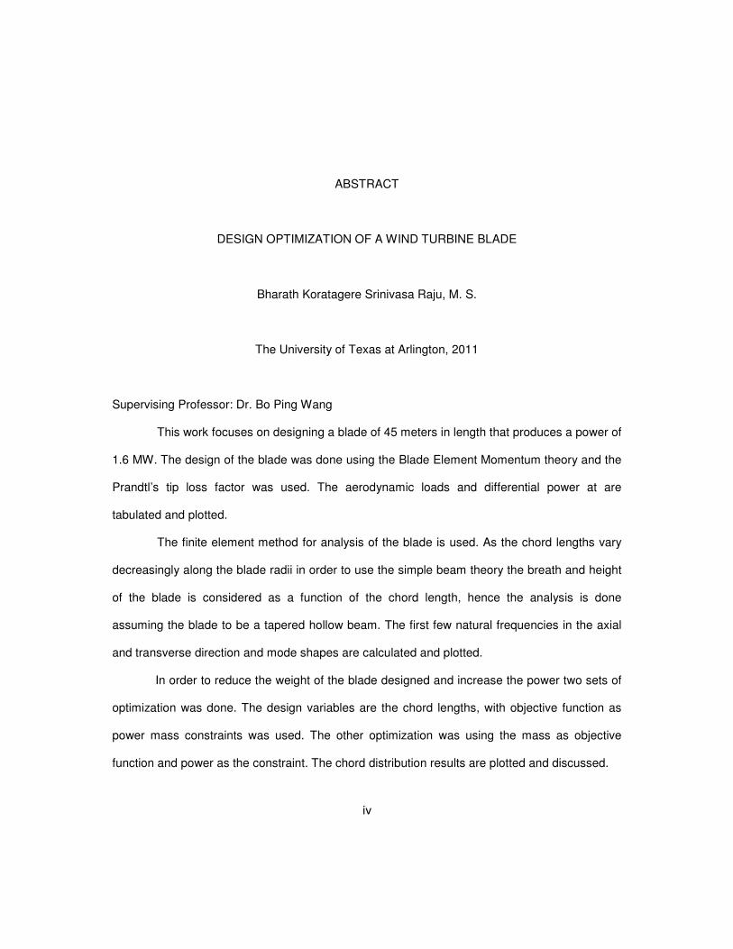
is a Coriolis force due to the rotation of the earth, the northern hemisphere the winds move
counter clockwise and the southern hemisphere it rotates clockwise figure 1.1 shows this effect.
Surface winds are affected by the obstacles on the earth up to a height of 100 meters. There
are winds called sea breeze and land breeze which can also be a source of wind. The Danish
wind industry association [18] has documented these results in more detail
The local winds are also influenced by the global and local effects, the landscape of the
region. The seasonal winds change too at places in south Asia. The winds around mountain
2
regions due to the pressure differences and the height of the hills make up for these kinds of
winds that are strong. Hence based on research it is conclusive that winds across the globe are
consistent, depending on the region as well figure 1.2 shows the currents across the globe.
Something that is so freely available in nature is a source where enormous power can
be harnessed and used. The clean, inexhaustible, constant everyday occurrence and green
energy part of this source is the essence why we need to choose as a part of our large
consumption of energy needs.
Figure 1.1 Coriolis Force [19]

3
Figure 1.2 Flow of Wind and Currents across the Globe [20]
A brief history goes on to show that harnessing wind energy was done for a variety of
purposes in as early as 7th century. The use of wind energy in getting water out of wells and
grinding was a part where this source was of great significance for free power. Older wind
capturing machines developed in 200 BC is considered to be the first instance where wind was
as a power source for machines. The European countries had built smock mill type of turbines
which was mainly used for drawing water from wells and for agricultural purpose, figure 1.3.

4
Figure 1.3 Smock Mill Wind Turbine [21]
The power of wind if harnessed completely can actually power a whole nation, and if
used with other natural alternative energy we can create a pollution free green environment.
This energy is so important to third world countries where basic electricity is not available.
Power of wind turbines has increased 100 times compared to the wind mills those existed a
couple of decades ago.
In order to harness the wind effectively and for the low costs, the advancement of
technology over the last few decades has given rise to not individual turbines but wind farms in

5
general. Advances in materials and composites used for construction of turbines, the analysis
for efficiency of aerodynamics and structures, accurate prediction of winds and their direction
have provided for cost effective production of power. As technology in every area is advancing
the turbines go higher and grow powerful. As Greenpeace international puts it, “Behind the tall,
slender towers and steadily turning blades lays a complex interplay of lightweight materials,
aerodynamic design and computer controlled electronics”.
There are two types of wind turbines that are developed, one is the vertical axis wind
turbines and the other is the horizontal axis wind turbines. The vertical axis is the kind where the
main rotor shaft is set vertically and perpendicular to the ground. The horizontal axis wind
turbines are those where the main shaft and rotation of blades is perpendicular to the direction
of wind. The former type is highly useful due to its ease of construction and in small scale for
small wind farms and single buildings but their efficiency is low for large scale applications. The
horizontal axis is used for large scale production of power and can be used in offshore as well
as on shore and can be efficient in small scale production in farms as well. Although the
aerodynamics of both are the same, the most preferred in industry for large scale production of
power is the horizontal axis wind turbines (HAWT) and is used as a standard in this thesis.
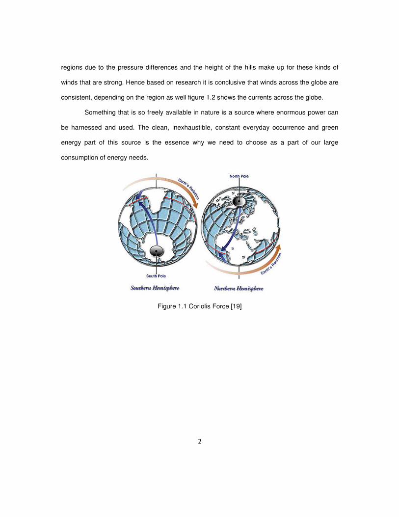
The first wind turbine of modern type was produced by Johannes Juul named the
Gedser Wind Turbine figure 1.5 was the first one built for a power of 200 KW in 1904. HAWT
are of various types depending on the number of blades ranging from one blade to any ode
number of blades. The three bladed rotors are the most industry accepted design and version.
The largest wind turbine today is the ‘Enercon E-126’ figure 1.5, which produces an excess of 7
MW of power producing about 20 million KWh per year. As wind turbines go higher and wider,
these can be used only at certain places. The usage of wind turbine in wind farms are of each
producing 1.5 MW and around 40-50 meters in length. Figure 1.4 gives an approximate rotor
diameter and years in production.

6
Figure 1.4 Rotor Diameter vs Years [23]
The aerodynamic efficiency is lower on a two bladed rotor compared to a three bladed
rotor, the rotation speed needs to be higher so as to achieve the same power as that of the
three bladed rotor. The two and single bladed rotors need a special kind of arrangement that is
hinged or teetering hub. Each time the rotor passes the tower and in order to avoid heavy
shocks the rotor is to tilt away. Also the arrangement can have balance issues and in time the
blades are bound to hit the tower during operation. The three bladed rotors are effective to use
the yawing mechanism in them.
Analysis of blades using wind tunnel would be possible for small scale rotors, but the
increase in diameters has called for the use of Computational Fluid Dynamics for fluid flow over
blades and prediction of loads.
7
Figure 1.5 Enercon and Gedser Wind Turbine [22, 18]

8
The current energy needs of man are dependent on carbon based fuels that are cheap
and easily accessible, but the limitation and the environmental effects it has staggeringly
improvised the need for alternate cleaner energy. The advancement of technology and the
greener energy needed for the luxuries of mankind are the prime reason for this report and also
the advancements as seen from figure 1.5.
For the use of alternative sources of energy, we need to bring in more laws and the
promotion of this is definitely an added advantage considering what natural calamities can do to
power plants that are dangerous as in the case of nuclear energy or the dangers of burning coal
and exhausting the reserves of carbon based fuel. It takes commitment and action on part of all
of human kind for promoting these energies.
In order to produce larger wind turbines the efficiency of the blades designed must be
optimum. Since turbines growing larger in diameter, the rotation speed is slow and hence power
production is dependent on high performing aerodynamic design, a rigid structure, advanced
composite materials and optimization techniques to maximize power minimize cost of
production are of importance and to be scientifically studied and implemented.
There is no perfect rotor design, the choice of parameters are just optimized to obtain
one of a kind of rotor, the different airfoils and the choice of material with the speed of rotation
and the wind speeds for which the turbine is designed just leads an understanding that
optimization is critical in the design phase of the wind turbine rotors.
In order to produce power efficiently medium scale turbines that are of 1 MW to 5 MW
capacities are designed. In order to be efficient in drawing power from the wind optimization
techniques are needed at various stages in design of the rotors to the arrangement of the
turbines in the wind farms is of importance.
A survey of literatures for this thesis has yielded that structural optimizations on blades
of lengths of well between 10 to 30 meters has been optimized for maximizing power and

9
decreasing the weight of the blades. The blades of length greater than 50 meters has a different
design concept and the usage of CFD is needed for optimizing aerodynamically and the
structures of the blades are very different. In most cases the small turbines are scaled
dimensionally for designing medium scale turbines, hence an initial estimate of how designing
and optimizing of a medium scale turbine from beginning forms the basis for this research.

10
CHAPTER 2
LITERATURE REVIEW
A significant amount of exhaustive research has been done in the area of small and
medium scale wind turbine blades and most of them have used the classical blade element
momentum theory for designing the blades and calculating the forces acting on it. Lot of
research on finding the optimum chord lengths has been made using a variety of evolutionary
optimizing techniques. Some work that forms the background for this research is as follows.
Mahri and Rouabah [1] had calculated the dynamic stresses on a blade which was
designed using the blade element theory. The rotor diameter was 10 meters and the dynamic
analysis was made using the beam theory and the modal analysis is made using the finite
element modeling and also using the blade motion equation. Mickael Edon [2] had designed a
blade for 38 meters for a 1.5MW power using the BEM theory, and had suggested in his future
work the chord distribution formula which I have implemented. Since his blade was close to my
design I choose the same airfoil profile.
Philippe Giguere and Selig [3] had described blade geometry optimization for the
design of wind turbine rotors, pre-programmed software was used to optimize structures and
cost model. M. Jureczko, M. Pawlak, A. Mezyk [4] used the BEM theory to design and used
ANSYS for calculation of natural frequencies. They had found out the mode shape of the blades
by using the Timoshenko twisted tapered beam element theory. The genetic algorithm was
used to minimize blade vibration, maximize output, minimize blade cost and increase stability.
Tingting Guo, Dianwen Wu, Jihui Xu, Shaohua Li [5] developed a 1.5 MW turbine rotor
of 35 meters blade length, using Matlab programming for designing and concluded the
feasibility of Matlab for designing large wind turbines, further they had also compared with CFD

11
results and the found out Matlab was economical in artificial design and optimizing for
efficiency. Carlo Enrico Carcangiu [6] used CFD tool FLUENT to a better understanding of fluid
flow over blades.
Jackson, et.al [7] made a preliminary design of a 50 meters long blade, two versions
one of fiber glass and one with carbon composite was used to test the cost and thickness of
cross sections was changed in order to improve structural efficiency. The aerodynamic
performance was made using computational techniques and the computations were predicted
using clean and soiled surface.
Wang Xudong, et al [8] used three different wind turbine sizes in order to optimize the
cost based on maximizing the annual energy production for particular turbines at a general site.
In their research using a refined BEM theory, an optimization model for wind turbines based on
structural dynamics of blades and minimizes the cost of energy. Effective reduction of the
optimization was documented.
Karam and Hani [9] optimized using the variables as cross section area, radius of
gyration and the chord length, the optimal design is for maximum natural frequency. The
optimization is done using multi dimensional search techniques. The results had shown the
technique was efficient.
Ming-Hung Hsu [10] has given a model for analysis of twisted tapered beams using the
spline collocation method. The expressions for cross sectional area and moment of inertias are
given which are used in this present work.
Rao and Gupta [11] used the finite element method for the analysis of twisted tapered
rotating Timoshenko beams. The stiffness and mass matrices are derived using the shape
functions and the natural frequency is found out by converting the problem to an Eigen value
problem.
12
B. Hillemer,et al [12] designed wind turbines which were to output beyond 5 MW and
they had scaled up existing rotors and further calculated stress, moments and natural
frequencies. For the analysis they had used the simple beam theory. The scaled up blades
were optimized for minimizing weight by changing the airfoil shell thickness and web and flange
at every cross section. The constraints used for their work being structural strength and
minimum weight.
J.H.M. Gooden [13] investigated two dimensional characteristics of FX 66 S 196 V1
airfoil which is the airfoil that has been used in this report. The coefficients of lift and drag for
various Reynolds number.
This present work is done in designing a wind turbine blade using the Blade Element
Theory for a length of 45 meters. The chord lengths are calculated using the formula in
reference [2] and the chord distributions, flow angles, the differential power, thrust and torque
are all at discrete intervals of the blade are plotted. The blade is then assumed to be a tapered
hollow beam and the stiffness and mass matrix are derived as explained in the reference [11].
The natural frequency is found out by solving the Eigenvalue problem. The first six natural
frequencies for axial and transverse direction are calculated. The mode shapes are plotted as
well. The optimization involves chord length as the design variables and the power and mass
were used as objective functions. The constraints are the natural frequency along with the
power or the mass depending on the optimization problem.

13
CHAPTER 3
AIRFOIL THEORY
3.1 Introduction
The most important part in designing a wind turbine blade is the choice of airfoil, as the
entire blade is made up of airfoils sections and the lift generated from this airfoil at every section
causes the rotation of the blade, also the performance of the blade is highly dependent on this
choice making the selection and study of the airfoil of prime importance. From Figure 3.1 we
can define the chord to be a straight line connecting the leading edge to the trailing edge of the
airfoil. The angle of attack is defined as the angle between the chord line and the free stream
velocity of air. All the forces generated from the airfoil act on the aerodynamic center which is
located about a fourth of the chord length from the leading edge of the airfoil.
The forces generated by the airfoil is resolved into lift the force perpendicular to the
direction of free flow of wind and the drag force in direction of the free flow of wind. The lift and
drag force are given by the expression,
21
2lL C cVρ=
(3.1)
21
2dD C cVρ=
(3.2)
lC and
dC
are the coefficients of lift and drag.

14
3.2 Reynolds Number
The forces over the airfoil change with respect to the fluid properties the length of the airfoil and
surrounding temperature. Hence a non dimensional parameter called the Reynolds number is
defined. The ratio between the inertia and viscous forces, given by the expression,
ce
VLR
ν=
(3.3)
V is the free stream velocity,
cL is the characteristic length of the chord,
ν is dynamic viscosity of air
The choice of airfoils is such that the maximum lift is obtained for a given angle of
attack. The Reynolds number for aircrafts are really high compared to the wind turbine blades,
hence airfoils used in aircraft wings cannot be used to design wind turbine blades. The ‘Wind
Turbine Catalogue’ from The Riso national laboratory of Denmark had provided data for a
variety of airfoil families for designing and choosing airfoils in the design of wind turbine blades.
Based on the catalogue for large wind turbine blade design the FX66-S196-V1 type of airfoil is
given to be the best. Although in some cases of blade design mixtures of airfoils are used from
the root to the tip end of the blade, this is true in case if the airfoil type has a group. The FX66-
S196-V1 does not have a family group hence I have designed the blade with the same airfoil
throughout.
The coefficient of lift versus angle of attack and coefficient of lift versus coefficient of
drag for various Reynolds number is show in the graphs below. Form the graphs it is evident the
optimum angle of attack for this airfoil is 9°.

15
Figure 3.1 Airfoil [25]
L
c/4

16
Figure 3.2 FX 66 S 196 V1 Coefficient of Lift Vs Angle of Attack [13]

17
Figure 3.3 FX 66 S 196 V1 Coefficient of Drag Vs Coefficient of Lift [13]
18
CHAPTER 4
AERODYNAMICS
4.1 Introduction
The principle of wind turbine is that the kinetic energy from the wind is converted to
mechanical energy. Before understanding the blade element momentum theory a brief ideal
rotor case understanding is essential. An ideal rotor is assumed such that no friction and there
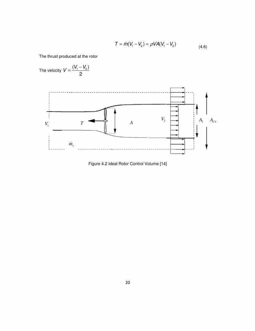
is no rotational velocity component in the wake. From the control volume figure below, the
velocity of air between upstream and downstream is reduced at the rotor. Expressions for thrust
and power with velocities are all derived. The pressure difference between upstream and
downstream is converted to thrust of the rotor given by expressionT A p= ∆ .
From Newton’s second law dp
Fdt
= where p is the momentum and t is time. Integrating over
control volume and applying the Newton’s second law is,
CV CS
dpF Vdv V VdA
dt tρ ρ
∂= = +
∂ ∫ ∫ ∫ ∫ ∫ (4.1)
21
2p V constρ+ =
(4.2)
From Bernoulli equation
2 2
1 1
1 1
2 2p V p Vρ ρ+ = + and
2 2
1 2
1 1
2 2p p V p Vρ ρ− ∆ + = +
2 2
1 2
1( )
2p V Vρ∆ = −
(4.3)

19
Figure 4.1 Ideal Rotor Velocity and Pressure Profiles [14]
Applying the conservation of mass from Figure 4.2
2 2 2
2 2 1 2 1 1 1( ( ) )CV s CVV A V A A V m V V A Tρ ρ ρ− + − + − =� (4.4)
Where 2 1 2( )sm A V Vρ= −�
The conservation of mass also gives the relation
2 2m AV A Vρ ρ= =� (4.5)
The above equations 4.4 and 4.5 give
1V
p
2V
p V
V
1V
2V
1p
20
1 2 1 2( ) ( )T m V V VA V Vρ= − = −� (4.6)
The thrust produced at the rotor
The velocity 1 2( )
2
V VV
−=
Figure 4.2 Ideal Rotor Control Volume [14]
T A 2
V CV
A
1V
2A
sm�

21
4.2 Betz Limit
A German physicist Albert Betz proved that the maximum that a wind turbine can
extract and convert the kinetic energy of wind to power is only 59.3%. This was termed as Betz’
limit and the proof is as follows. Assuming a rotor, the mass of air moving through the rotor is
1 2
2
V Vm Aρ
+ =
(4.7)
The power extracted at the rotor from wind is
2 2
1 2
1( )
2P m V V= −
(4.8)
From equation 4.7 and 4.8
2 2
1 2
1( )
2P AV V Vρ= −
(4.9)
The total power available in the wind is given
3
1
1
2oP AVρ=
(4.10)
The coefficient of power is the ratio between the actual power of rotor to available
power given by the expression
2
2 2
1 1
11 1
2P
o
V VPC
P V V
= = − +
Plotting a graph for PC versus 2
1
V
V
we get plot as

22
Figure 4.3 Betz Limit
4.3 Induction Factor
The drop in velocity of the free stream of air at the rotor in the axial direction we
introduce an axial induction factor a , expressed as
1(1 )V a V= − (4.11)
The thrust and power expressions in terms of axial induction factor are
3 2
1
2 2
1
2 (1 )
2 (1 )
P AV a a
T AV a a
ρ
ρ
= −
= − (4.12)
The aerodynamic shape of the blade causes a torque on the rotor when it comes in
contact with the wind. The thrust is produced as a consequence of the torque. The torque is a
force exerted by the wind on the blades. According to Newton’ third law an equal and opposite
reaction the blades exerts a force on the wind causing the air behind the rotor to rotate in the
opposite direction to that of the rotor. This induced tangential velocity in the wake of the rotor
gives the tangential induction factor given by
(1 ')rotV a rω= + , where r is the radial distance from the center of the rotor.

23
Figure 4.4 Velocity Triangle Over Airfoil
The relative velocity component is the actual velocity induced on the element of the
blade. Since the rotation of the blade and the velocity of free stream of air is perpendicular to
each other, the relative velocity of air hitting the blade is dependent on the radius of the blade,
in turn the induction factors.
W
1V
Rotor direction
'a rω
φ aV
rω
φ
L
relV
V

24
4.4 Tip Speed Ratio
The tip speed ratio is the ratio between the rotor rotational speed and the free stream
velocity of the wind given by
1
R
V
ωλ = . The local tip speed ratio is given by
1
rx
V
ω= . The tip
speed ratio affects the angular velocity of the rotor in turn the rotations per minute of the blade.
The tip speed ratio is of prime importance while designing a wind turbine as it affects the twist of
the blade and the power produced.
4.5 Pitch, Twist and Chord Lengths
Since the induction factors are dependent on radius of the element along the blade, it is
evident that the inductions factors changes. The velocity triangle for the induction factors are as
shown below explains the relative velocity component.
4.5.1 Pitch
As wind turbines go higher the range of operating speeds also needs to increase hence
the turbines are designed for a wide range of wind speeds. In figure 4.5, the top images show
the free stream velocity at both low and high speed and because of which the relative velocity
changes and in order for the optimum angle of attack of the blade to face the wind, the entire
blade has to be pitched.
25
Figure 4.5 Pitch and Twist with Velocity Triangles [2]
4.5.2 Twist
In the left half of figure 4.5 the top and bottom images show the relative velocity across
the length of the blade changes as the rotation speeds vary along the blade length, due to
which the entire section of the blade made up of a number of airfoil strips needs to face the wind
at optimum angle of attack of the incoming wind, hence the blades are twisted throughout.
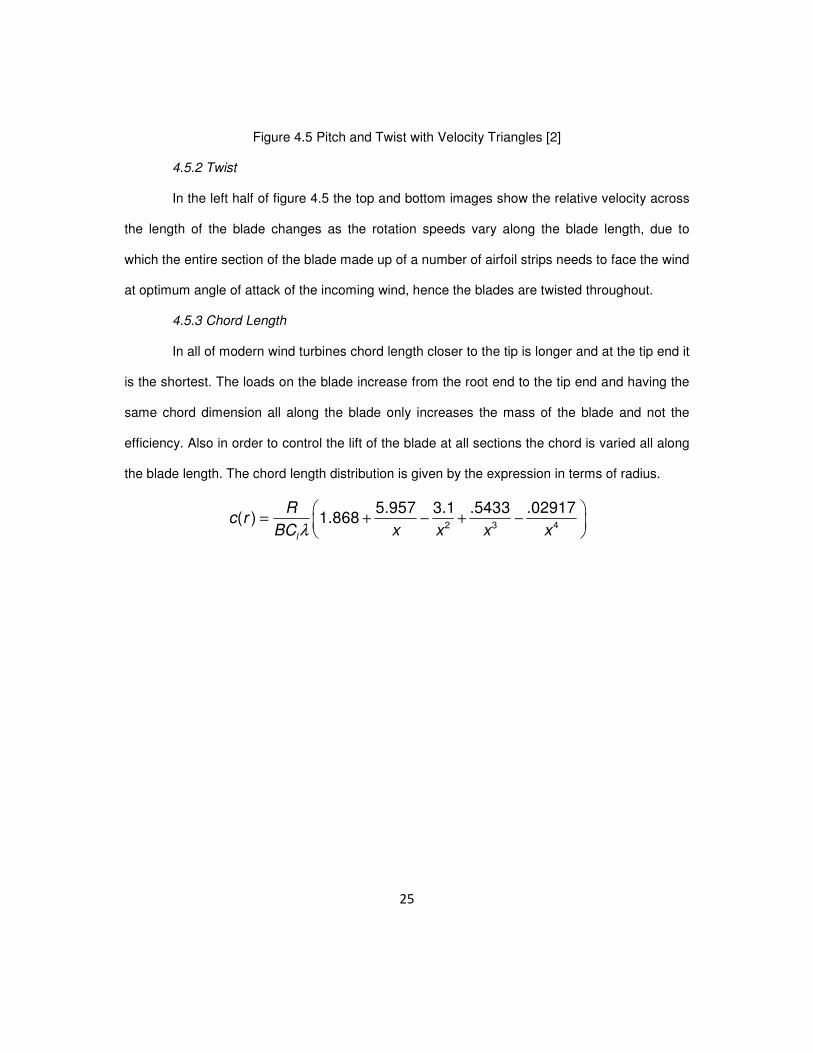
4.5.3 Chord Length
In all of modern wind turbines chord length closer to the tip is longer and at the tip end it
is the shortest. The loads on the blade increase from the root end to the tip end and having the
same chord dimension all along the blade only increases the mass of the blade and not the
efficiency. Also in order to control the lift of the blade at all sections the chord is varied all along
the blade length. The chord length distribution is given by the expression in terms of radius.
2 3 4
5.957 3.1 .5433 .02917( ) 1.868
l
Rc r
BC x x x xλ
= + − + −

26
CHAPTER 5
BLADE ELEMENT MOMENTUM THEORY
The classical blade element momentum theory was developed in order to predict the
behavior of propellers. This method was also used to determine the loads on the blade. This
theory has been used constantly to design propeller blades of helicopters, aircrafts and also the
blades for harnessing wind power. The simplicity of this theory gives all the performance
parameters like thrust and power of any blade that is designed. The theory begins with the
conservation of momentum theory. The blade to be designed is divided into discrete elemental
sections, also the independency of each element, i.e. the neighboring elements are
independent of the forces acting on each element. Another assumption is the force from the
blades onto the flow is constant for each discrete element, this indicates an assumption of an
infinite number of blades. The correction for this assumption is incorporated in this thesis work
and explained later. This iterative method is used to calculate the flow angles, the differential
thrust, torque and power. Once the differential toque and power are known and integrated along
the blade element to obtain total power of the blade. This theory uses aerodynamic data from
the airfoils chosen and also the specific chord lengths. A basic flow chart is given later in this
chapter.

27
Figure 5.1 Velocity Triangle of A Section of Wind Turbine Blade
The differential thrust and torque is given by
2
1
3
1
4 (1 )
4 '(1 )
dT r V a a dr
dM r V a a dr
π ρ
π ρ ω
= −
= − (5.1)
From the given velocity triangle diagram we see that the angle of attack and twist of the blade
section is given by
1(1 )tan
(1 ')
a V
a r
α φ θ
φω
= −
−=
+ (5.2)
The lift and drag are given by equations
2
2
1
2
1
2
rel l
rel d
L V cC
D V cC
ρ
ρ
=
= (5.3)
1(1 )a V−

28
Figure 5.2 Normal Forces over Airfoil [14]
As the forces on in the normal and tangential direction to the rotor plane are important, the lift
and drag forces when resolved as shown in figure give expression as
cos sin
sin cos
N
T
P L D
P L D
φ φ
φ φ
= +
= − (5.4)
When the normal and tangential forces are normalized with respect to 21
2relV cρ the
expressions in terms of &l dC C are
cos sin
sin cos
n l d
t l d
C C C
C C C
φ φ
φ φ
= +
= − (5.5)
Where 2 2
&1 1
2 2
N Tn t
rel rel
P PC C
V c V cρ ρ= =

29
A parameter called the solidity is defined as the ratio of the area of the blades to the swept area
of the rotor, given by the expression ( )
( )c r B
rr
σπ
=
The differential thrust and torque in terms of normal and tangential forces on the control volume
of thickness dr are
N
T
dT BP dr
dM rBP dr
=
= (5.6)
The expression for differential thrust and toque on substitution for &N TP P
2 2
1
2
1
(1 )1
2 sin
(1 ) (1 ')1
2 sin cos
n
t
V adT B cC dr
V a r adM B cC rdr
ρφ
ωρ
φ φ
−=
− +=
(5.7)
On equating the thrust and toque equations we get expressions for the induction factors as
2
1
4sin1
1'
4sin cos1
n
t
a
C
a
C
φ
σ
φ φ
σ
=
+
=
− (5.8)
Since all the expressions are for an ideal rotor case and of infinite blades we introduce
a parameter called the Prandtl’s Tip Loss Factor. This correction changes the vortex system of
the wake for finite number of blades. The correction F incorporated into the thrust and torque
equations are,
2
1
3
1
4 (1 )
4 '(1 )
dT r V a a Fdr
dM r V a a Fdr
π ρ
π ρ ω
= −
= − (5.9)

30
The Prandtl’s correction factor F
12cos ( )
( )
2 sin
fF e
B R rf
r
π
φ
− −=
−=
(5.10)
The induction factors expressions change to
2
1
4 sin1
1'
4 sin cos1
n
t
aF
C
aF
C
φ
σ
φ φ
σ
=
+
=
− (5.11)
The flow chart for the Blade element momentum theory is given as follows

31
Once the values of & 'a a converge the differential thrust and torque can be calculated. The
power of the blade is computed by dP dMω=
Guess initial
value of a and a’
1(1 )tan
(1 ')
a V
a r
α φ θ
φω
= −
−=
+
cos sin
sin cos
n l d
t l d
C C C
C C C
φ φ
φ φ
= +
= −
2
1
4sin1
n
a
C
φ
σ
=
+
1
'4sin cos
1t
a
C
φ φ
σ
=
−
Check for convergence
of a and a’
a and a’
Y
N

32
CHAPTER 6
RESULTS
From the above concepts the blade of the wind turbine was designed and the
calculated values are as follows.
The length of the blade was chosen to be 45L = meters.
The radius of rotor is 46R = meters.
The tip speed ratio is 6TSR = .
The coefficient of performance was chosen to be as PC =0.4.
The free stream velocity of air is chosen as V =12 m/s.
The rotation speed of the blade based on the TSR was calculated to be
1.56V
TSRR
ω
= =
The rotation per minute 30
14.94RPM ωπ
= =
As the stresses on the root end of the blade will be high having an airfoil shape at the
root end is not feasible hence the root end is circular in shape and then transcends to an airfoil
shape is needed. This transition length of 4 meters was used.
I have taken 40 elements of 1 meter span across the entire blade and the chord lengths
were calculated but the distribution of chord lengths was from 9.5 m to 4.9 m. the length of the
chord near the root end was very large and after studying various literatures the size of the
chord at the root end for large wind turbines I came up with a distribution ranging from 3.72 m to

33
1.94 m. Using the blade element momentum theory, the twist of the blades, differential thrust,
torque and power are calculated.
The plots of chord distribution, twist or flow angle distribution, differential power, thrust
and torque are plotted with respect to radius.
Figure 6.1 Chord Distribution
The chord lengths in meters along the length of the blade element, from 3.72 meters at
4 metes of the blade length to 1.94 meters at 44 meters of the blade element.

34
Figure 6.2 Twist Distribution
The degrees of twist in degrees along the length of the blade element, from 42.210 at 4 metes of
the blade length to -3.430 at 44 meters of the blade element.

35
Figure 6.3 Differential Power

36
Figure 6.4 Differential Thrust

37
Figure 6.5 Differential Torque

38
Table 6.1 Distribution of Differential Thrust, Torque, Power and Flow Angles
radius (m) Chord lengths
(m)
Thrust x10^5
(N)
Torque
(MN.m) Power (MW)
twist
(deg)
4 3.7235 0.4969 0.1899 0.2971 42.2153
5 3.8331 0.6278 0.2589 0.405 38.022
6 3.7967 0.7554 0.3277 0.5126 34.2509
7 3.7009 0.8862 0.3971 0.6213 30.8194
8 3.5843 1.0228 0.4682 0.7324 27.7142
9 3.464 1.1667 0.5412 0.8468 24.9219
10 3.3475 1.3184 0.6166 0.9647 22.4206
11 3.2381 1.4781 0.6945 1.0866 20.183
12 3.1367 1.6459 0.7749 1.2124 18.1802
13 3.0434 1.8217 0.8578 1.342 16.3845
14 2.9577 2.0055 0.943 1.4753 14.7705
15 2.8791 2.1972 1.0305 1.6122 13.3153
16 2.8069 2.4043 1.1195 1.7514 11.9735
17 2.7406 2.6125 1.211 1.8946 10.778
18 2.6794 2.8282 1.3043 2.0405 9.6891
19 2.623 3.0513 1.3993 2.1891 8.6941
20 2.5708 3.2911 1.4944 2.3379 7.7608
21 2.5224 3.53 1.5919 2.4905 6.9207
22 2.4774 3.7759 1.6905 2.6448 6.1455

39
Table 6.1 continued
radius (m) Chord lengths
(m)
Thrust x10^5
(N)
Torque
(MN.m) Power (MW)
twist
(deg)
23 2.4355 4.0386 1.7881 2.7975 5.4103
24 2.3964 4.2994 1.8879 2.9537 4.7435
25 2.3598 4.5667 1.988 3.1103 4.1228
26 2.3255 4.8507 2.0859 3.2634 3.5276
27 2.2934 5.1311 2.1854 3.4191 2.9846
28 2.2631 5.4167 2.2842 3.5737 2.4753
29 2.2346 5.7187 2.379 3.7219 1.981
30 2.2078 6.0139 2.4744 3.8713 1.5285
31 2.1824 6.3236 2.5643 4.012 1.0867
32 2.1583 6.6237 2.6537 4.1517 0.6805
33 2.1356 6.935 2.7353 4.2794 0.2812
34 2.114 7.2315 2.8142 4.4029 -0.0872
35 2.0934 7.5332 2.882 4.5089 -0.4523
36 2.0739 7.8227 2.9397 4.5992 -0.8026
37 2.0553 8.0927 2.9845 4.6693 -1.1402
38 2.0376 8.3329 3.0124 4.7129 -1.4669
39 2.0206 8.5285 3.0179 4.7216 -1.7848
40 2.0045 8.6573 2.9937 4.6837 -2.096
41 1.989 8.6974 2.9253 4.5766 -2.4135
42 1.9742 8.5855 2.8005 4.3814 -2.7304
43 1.96 8.2444 2.5908 4.0533 -3.0626
44 1.9464 7.5165 2.2487 3.5181 -3.4317

40
CHAPTER 7
STRUCTURAL ANALYSIS
7.1 Simple Beam Theory
The structural analysis of the blade was done by performing the modal analysis of the
blade (calculating the natural frequency). This finite element method is used in order to obtain
the stiffness and mass matrices. The blades are assumed to be a hollow rectangular beam
element while performing the analysis with the breadth and depth as a function of the chord
length. Since the assumption involves the chord as a parameter for determining the dimensions
of the blade element and since chord length is largest at the root end and smallest at the tip,
hence the beam is to be analyzed as a tapered beam.
Considering a beam element and the displacements and moments at the nodes are as
shown. A linear elastic beam equation is derived as follows. The beam is subjected to a load in
the y direction, as ( )w x . Choosing an element of the beam and from force and moment
equilibrium,
ˆ( ) 0w dx dR− + =
ˆdRw
dx= −
(7.1)
ˆ ( ) 0R dx dM+ =
ˆ dMR
dx=
(7.2)
Curvature of the beam is given by

41
1 M
EIκ = =
Θ (7.3)
Where Θ is the radius of deflection. E is Young’s modulus, I is the moment of inertia, the
expressions for these is given later for tapered beams.
2
2
d v
dxκ =
(7.4)
v is the deflections in the axial and tangential direction.
2
2
d v M
dx EI∴ =
(7.5)
Substituting into equations 7.1 and 7.2 after solving for moment force M from 7.5,
2 2
2 2( )
d d vEI w x
dx dx
= −
(7.6)

42
Figure 7.1 Reaction and Moments of A Beam [15]
43
Figure 7.2 Tapered Cantilever Beam [11]
From figure 7.2 cross sectional area of the beam changes with respect to radius ‘r’. The area is
given as a function of radius as,
( ) ( ) ( )A r b r h r=
1 1( ) 1 1r r
A r b hR R
= + Μ + Ν
(7.7)
2 1 2 1
1 1
&b b h h
b h
− −Μ = Ν =
r
R
ez
x
r
y
1V 2V 3V 4V

44
&b h are the breadth and height.
The moment of inertia is given by
33
1 1( ) 1 112
xx
b h r rI r
R R
= + Μ + Ν
33
1 1( ) 1 112
yy
b h r rI r
R R
= + Μ + Ν
(7.8)
Choosing a displacement function as
3 2
1 2 3 4( )v x a r a r a r a= + + + (7.9)
As shown in the figure since the degrees of freedom is 4 the cubic displacement function is
chosen. Further expressing v as a function of nodal degrees of freedom 1 2 3 4, , ,v v v v as shown
in the figure 7.2,
1 4
2 3
3 2
3 1 2 3 4
2
1 2 3
(0)
(0)
( )
( ) 3 2
v v a
dv v a
dx
v r v a r a r a r a
dv r a r a r a
dx
= =
= =
= = + + +
= + +
(7.10)
Solving for 1 2 3 4, , ,a a a a and substituting in equation
3 2
1 3 2 4 1 3 2 4 2 13 2 2
2 1 3 1( ) ( ) ( ) ( )v v v v v x v v v v x v x v
L L L L
= − + − + − − − − + + (7.11)
In matrix form the expression is given by ˆ[ ]v N d=

45
1 2 3 4[ ] [ ]N N N N N= and
1
2
3
4
ˆ
v
vd
v
v
=
Where
3 2
3 21
2
3 23
4
3 2
2 3 1
2
2 3
x x
L L
N x xL L x
N L L
N x x
N L L
x xL L
L L
− +
− + =
− +
−
are the shape functions.
From beam element theory the assumption that the cross section does not deform in
shape even with the bending of the beam. Strain of the element is given as,
2
2( , )x
d vx y y
dxε = −
(7.12)
From the beam element theory, the traverse displacement function and the bending
moment and shear force are related.
2
2( )
d vM r EI
dx=
And
3
3ˆ d v
R EIdx
= (7.13)

46
7.2 Stiffness Matrix
Using the nodal and beam theory and the equation 7.11 and 7.13
3
1 1 2 3 43 3
22 2
2 1 2 3 42 3
3
3 1 2 3 43 3
22 2
4 1 2 3 42 3
(0)ˆ (12 6 12 6 )
(0)(6 4 6 2 )
( )ˆ ( 12 6 12 6 )
( )(6 2 6 4 )
d v EIf R EI v Lv v v
dx L
d v EIf m EI Lv L v Lv L v
dx L
d v L EIf R EI v Lv v v
dx L
d v L EIf m EI Lv L v Lv L v
dx L
= = = + − +
− −= = = + − +
= − = − = − − + −
= = = + − + (7.14)
ˆF Kd=
1 1
2 22 2
3
3 3
2 2
4 4
12 6 12 6
6 4 6 2
12 6 12 6
6 2 6 4
f vL L
f vL L L LEI
f vL L L
L L L Lf v
− − = − − −
−
2 2
3
2 2
12 6 12 6
6 4 6 2
12 6 12 6
6 2 6 4
L L
L L L LEIK
L L L
L L L L
− − = − − −
−

47
7.3 Mass Matrix
For modal analysis the usage of lumped mass matrix although easier, the mass matrix derived
from shape functions yields better results. The mass matrix is given by,
0
[ ] [ ] [ ]L
T
A
M N N dAdxρ= ∫ ∫∫
2 2
2 2
156 22 54 13
22 4 13 3[ ]
420 54 13 156 22
13 3 22 4
L L
L L L LALM
L L
L L L L
ρ
− − = − − − −
From the stiffness and mass matrix the natural frequency of the beam element can be
computed by solving it as an eigenvalue problem ( ) 0K M vλ− = .
In order to find the natural frequencies in the transverse and axial directions the following
expressions for stiffness matrix and mass matrix is used.
Transverse direction
2 2
3
2 2
12 6 12 6
6 4 6 2
12 6 12 6
6 2 6 4
xx
L L
L L L LEIK
L L L
L L L L
− − = − − −
−
and
2 2
2 2
156 22 54 13
22 4 13 3[ ]
420 54 13 156 22
13 3 22 4
L L
L L L LALM
L L
L L L L
ρ
− − = − − − −
Axial direction
2 2
3
2 2
12 6 12 6
6 4 6 2
12 6 12 6
6 2 6 4
yy
L L
EI L L L LK
L L L
L L L L
− − = − − −
−
and
2 2
2 2
156 22 54 13
22 4 13 3[ ]
420 54 13 156 22
13 3 22 4
L L
L L L LALM
L L
L L L L
ρ
− − = − − − −
7.4 Mode Shapes
In order to find the mode shapes of the beam, transverse vibration of Bernoulli-Euler beams,
48
( ")" 0EIV Avρ+ =�� (7.15)
An assumption of harmonic motions is made,
( , ) ( )cos( )v x t V x tω= − Θ (7.16)
Substituting equation 7.16 in 7.15
2( ")" 0EIv A Vρ ω− = (7.17)
This equation reduces to
44
40
d VV
dxλ− =
(7.18)
where
24 A
EI
ω ρλ =
The general solution to the above differential equation is given by
1 2 3 4( ) sinh( ) cosh( ) sin( ) cos( )V x C x C x C x C xλ λ λ λ= + + + (7.19)
The boundary conditions used for the beam is the cantilever beam conditions which are,
2 3
2 3
@ 0
(0)(0) 0; 0
@
( ) ( )0; 0
x
dVV
dx
x L
d V L d V L
dx dx
=
= =
=
= = (7.20)
On using these conditions in equation

49
2 4
1 2 3 4
22
1 2 3 42
33
1 2 3 43
( sinh( ) cosh( ) sin( ) cos( ))
( sinh( ) cosh( ) sin( ) cos( ))
( sinh( ) cosh( ) sin( ) cos( ))
V C C
dVC x C x C x C x
dx
d VC x C x C x C x
dx
d VC x C x C x C x
dx
λ λ λ λ λ
λ λ λ λ λ
λ λ λ λ λ
= +
= + + +
= + − −
= + − − (7.21)
In matrix form,
1
2
2 2 2 2
3
3 3 3 3
4
0 1 0 1 0
0 0 0
sinh cosh sin cos 0
sinh cosh sin cos 0
C
C
CL L L L
L L L L C
λ λ
λ λ λ λ λ λ λ λ
λ λ λ λ λ λ λ λ
= − −
− − (7.22)
As the first two equations give a trivial solution, and in order to find the coefficients a
characteristic equation of the form
cos( )cosh( ) 1L Lλ λ = − (7.23)
The solution for this characteristic equation is solved in […] and the first four values are
1
2
1.8751
4.6941
L
L
λ
λ
=
=and
3
4
7.8548
10.996
L
L
λ
λ
=
=
From the four equation (7.22) we get,
1 3C C= − and 2 4C C= −
The third equation in equation (7.22) and the above equation give
1 2 3 4sinh( ) cosh( ) sin( ) cos( ) 0C x C x C x C xλ λ λ λ+ − − =
1 2(sinh( ) sin( )) (cosh( ) cos( ))C x x C x xλ λ λ λ+ + +
1 2 2
cosh( ) cos( )
sinh( ) sin( )r
x xC C C
x x
λ λχ
λ λ
+= − = −
+
50
The mode shape is given by the expression
( ) [(cosh( ) cos( )) (sinh( ) sin( ))]r rx C L L L Lφ λ λ χ λ λ= + − + (7.24)
7.5 Breadth and Height
In the analysis of the blades I have used the hollow beam theory and the breath and height of
the beam is considered as a function of the chord. The thickness of the element is 20% of the
original breath and height. Hence the area and moment of inertias are given as follows
1 1 2 2
1 1 2 2
0.8 & 0.8
0.8 & 0.8
B b B b
H h H h
= =
= =
2 1 2 11 1
1 1
2 1 2 12 2
1 1
&
&
b b h h
b h
B B H H
B H
− −Μ = Ν =
− −Μ = Ν =
33
1 11 1 1
33
1 12 2 2
( ) 1 112
( ) 1 112
xx
xx
b h r rI r
R R
B H r rI r
R R
= + Μ + Ν
= + Μ + Ν
1 2( ) ( )xx xxIxx I r I r= −

51
The first six natural frequencies are given as follows.
Table 7.1 Natural Frequency in the Transverse Direction
Frequency number Natural frequency
(rad/s)
1 301.1736
2 429.8942
3 498.3677
4 582.6563
5 677.6906
6 789.1982
Table 7.2 Natural Frequency in the Axial Direction
Frequency number Natural frequency
(rad/s)
1 1505.9
2 2149.5
3 2491.8
4 2913.3
5 3388.5
6 3946
The first four mode shapes of the beam are as follows given in the graphs below.

52
Figure 7.3 First Mode Shape
Figure 7.4 Second Mode Shape

53
Figure 7.5 Third Mode Shape
Figure 7.6 Fourth Mode Shape

54
CHAPTER 8
DESIGN OPTIMIZATION
The optimization process in the designing of wind turbines is always essential owing
due to the myriad of parameters that can be varied. As depending on what the design variables
and objective function determines the outcome of the optimization. There is no unique answer in
optimization problems; it is just the physics of the problem that yields the appropriate results
depending on the choice of input variables.
For this work the ‘fmicon’ function in Matlab was used as the optimization tool to
optimize the blade. The design variable was chosen to be the chord length. Since only Matlab
was used and a constant airfoil profile was used, the design variable had to only the lengths of
the chord across the blade element.
Various problems for constrained problems were performed, with only the chord lengths
as the design variable, the power could be maximized or the weight of the blade could be
minimized, where one is constraint and the other is the objective function could be used. As the
natural frequency is used constraints or the deflection to be minimized can also be done. This
report has a study of how the results are generated based on the following problems,

55
Table 8.1 Optimization problem definition
OBJECTIVE FUNCTION CONSTRAINTS
Maximize Power Mass
Minimize Mass Power
Minimize Mass Power and Natural Frequency
The flow chart as to how the optimization process was implemented is as follows.
Chord and radius
Thrust, Torque
Power and flow
angle
Natural Frequency
Constraint
Optimal Chord length
Blade
element
theory
Stiffness &
Mass matrix
N
Y
Figure 8.1 Flow Chart of Optimization Process

56
Problem 1: with the objective function is power and constraint of mass less than 7000
Kilograms, the optimization yielded, the following chord length distribution, twist, differential
power and thrust across the blade element.
Figure 8.2 Optimized Chord Distribution Problem 1
57
Figure 8.3 Optimized Twist Distribution Problem 1

58
Figure 8.4 Optimized Differential Thrust Problem 1

59
Figure 8.5 Optimized Differential Power Problem 1

60
The power and mass of the blade before and after optimization is tabulated,
Table 8.2 Original and Optimized Power and Mass Problem 1
Power MW Mass in Kilograms
Original 1.5787 13060
Optimized 1.7232 6806.8
Table 8.3 First Three Natural Frequencies Transverse Direction Problem 1
Optimized rad/sec Original rad/sec
269.3 301.1736
359.5 429.8942
389.5 498.3677
Table 8.4 First Three Natural Frequencies Axial Direction Problem 1
Optimized rad/sec Original rad/sec
1346 1506
1798 2149
1947 2492

61
Problem 2: Objective function Mass and constraint of Power greater 1.7 MW, the optimization
yielded, the following chord length distribution, twist, differential power and thrust across the
blade element
Figure 8.6 Optimized Chord Distribution Problem 2
From this problem it is evident that the physics of the problem yields results with constant chord
length and still satisfies the constraints of power. As the disadvantages of having a constant
chord throughout the length of the blade are higher, this result although right cannot be taken
into account. With constant chord the aerodynamics at the root end is not efficient and hence
practically not feasible. The lower bound on the problem is changed and the results are checked
again. The results after changing the lower bounds yield

62
Figure 8.7 Optimized Chord Distribution Problem 2

63
Figure 8.8 Optimized Twist Distribution Problem 2

64
Figure 8.9 Optimized Differential Power Problem 2

65
Table 8.5 Original and Optimized Power and Mass Problem 2
Power MW Mass in Kilograms
Original 1.5787 13060
Optimized 1.6825 9106
Table 8.6 First Three Natural Frequencies Transverse Direction Problem 2
Optimized rad/sec Original rad/sec
288.9 301.1736
403 429.8942
448.6 498.3677
Table 8.7 First Three Natural Frequencies Axial Direction Problem 2
Optimized rad/sec Original rad/sec
1444 1506
2015 2149
2243 2492

66
As seen from the results the constraints are violated in the frequency. Due to the fact
that we cannot predict the lower bounds for all the problems, we do not consider this
optimization to be precise, as only an initial guess is possible, but the results are not wrong they
are unique as it is for defining the optimization problem.
Problem 3: Objective function is the mass with the constraints natural frequency greater than
300 and power greater than 1.7 MW, the optimization results yielded, are
Figure 8.10 Optimized Chord Distribution Problem 3
67
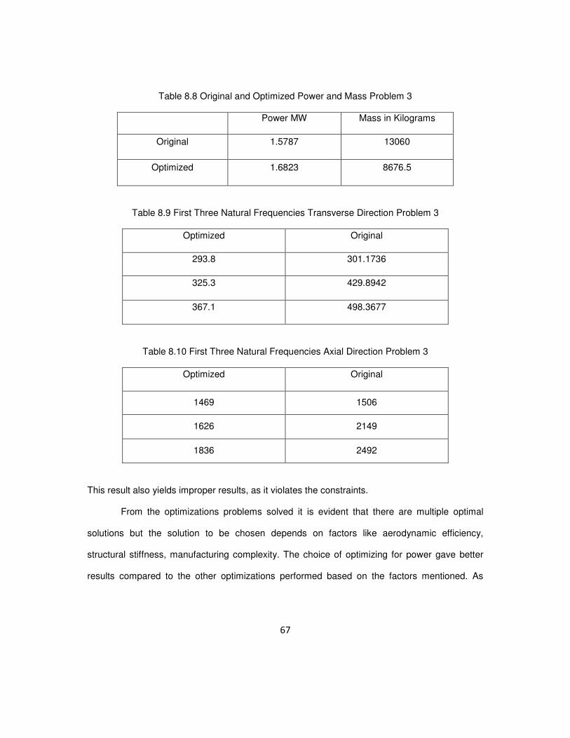
Table 8.8 Original and Optimized Power and Mass Problem 3
Power MW Mass in Kilograms
Original 1.5787 13060
Optimized 1.6823 8676.5
Table 8.9 First Three Natural Frequencies Transverse Direction Problem 3
Optimized Original
293.8 301.1736
325.3 429.8942
367.1 498.3677
Table 8.10 First Three Natural Frequencies Axial Direction Problem 3
Optimized Original
1469 1506
1626 2149
1836 2492
This result also yields improper results, as it violates the constraints.
From the optimizations problems solved it is evident that there are multiple optimal
solutions but the solution to be chosen depends on factors like aerodynamic efficiency,
structural stiffness, manufacturing complexity. The choice of optimizing for power gave better
results compared to the other optimizations performed based on the factors mentioned. As

68
there is no perfect answer in optimizing and certainly not unique, the results can vary depending
on the problem formulation.

69
CHAPTER 9
CONCLUSION
In this thesis a wind turbine blade of 45 meters in length and a wind speed of 12 m/s
was designed using the blade element moment theory where the flow angles and differential
thrust, torque and power was calculated. The blade designed was further analyzed as a hollow
tapered beam and the stiffness and mass matrices were calculated with the cross sectional
area and moment of inertia was calculated as mentioned in reference [11], for a tapered beam.
The chord lengths at every section determined the taper and breadths and the height of the
beam was also a function of the chord length and assumed to be the thickness of the airfoil. The
natural frequencies in the axial and transverse direction are tabulated.
After analysis the blade was optimized using Matlab as a tool and fmincon as the
function. The design variables were the chord lengths and three different optimization problems
were solved. With using power as the objective function and mass as a constraint the first set of
optimized chord lengths were plotted as well as the differential thrust, torque and power. The
second and third optimization was done with the objective function as mass and constraint as
power and natural frequency.

70
CHAPTER 10
FUTURE WORK
Further studies on the optimum composite layering for the blades so that the optimal
design for stress and weight can be found out is one of the prime continuation of the work, with
the introduction of the composite layering gives a better understanding of the behavior of the
blades dynamic qualities.
This report gives only an understanding how we can start designing process of a wind
turbine blade and optimizing it for performance structurally. The future of this work could be to
include interactions between multiple airfoil data and aerodynamically optimizing the blade for
aerodynamic performance. More often the larger blades are scaled from smaller ones as they
are already proven to be efficient, so in order to improvise on aerodynamics inclusion of CFD
analysis simultaneously for determining the aerodynamic parameters and structural analysis of
the blade using Ansys for a better understanding of how the analysis and design of the blade
could be improved can be determined. If an airfoil database is created from where data can be
input, optimizations based on wider design variables can be formulated.
The optimization techniques used in this work was fmincon in Matlab, but there are
other evolutionary algorithms that can be used for optimizing the blades. If the design variables
are increased to incorporate other parameters of the blade the possibility of designing blades of
high efficiency at less time is possible, basically finding the global optimum value in a whole set
of optimum values.

71
APPENDIX A
LIST OF SYMBOLS

72
a Axial induction factor
'a Tangential induction factor
B Number of blades c Chord length
PC Coefficient of power
&n tC C Coefficient of normal and tangential force
dM Differential torque
dT Differential thrust
F Prandtl’s tip loss factor
&xx yyI I Moment of inertia
K Stiffness matrix
L Length of blade
M Mass matrix m Mass of air flowing over rotor
P Power
&n tP P Normal and tangential force over airfoil
R Radius of rotor
V Velocity of free stream air
1V Velocity of air farthest from the rotor
relV Relative velocity of air over blade/airfoil
x Local tip speed ratio ω Angular velocity of rotor
α Angle of attack
φ Flow angle
θ Local pitch angle
λ Tip speed ratio
( )xλ Eigenvalue

73
REFRENCES
[1] Z.L. Mahri, M.S. Rouabah, “Calculation of dynamic stresses using finite element
method and prediction of fatigue failure for wind turbine rotor“ Wseas Transactions
On Applied And Theoretical Mechanics, Issue 1, Volume 3, January 2008
[2] Mickael Edon, “38 meter wind turbine blade design, internship report“
[3] Philippe Giguere and Selig, “Blade Geometry Optimization For The Design Of Wind
Turbine Rotors” AIAA-2000-0045
[4] M. Jureczko, M. Pawlak, A. Mezyk, “Optimization of wind turbine blades“, Journal of
Materials Processing Technology 167 (2005) 463–471
[5] Tingting Guo, Dianwen Wu, Jihui Xu, Shaohua Li, “The Method of Large-scale Wind
Turbine Blades Design Based on MATLAB Programming”, IEEE
[6] Carlo Enrico Carcangiu, “CFD-RANS Study of Horizontal Axis Wind Turbines” ,Doctor
of philosophy Thesis report
[7] K.J.Jackson, et al., “Innovative design approaches for large wind turbine blades”, 43rd
AIAA Aerospace Sciences Meeting and Exhibit 10 - 13 January 2005, Reno, Nevada
[8] Wang Xudong, et al.,”Blade optimizations for wind turbines”, Wind Energy. 2009;
12:781–803, Published online 29 April 2009 in Wiley Interscience
[9] Karam Y, Hani M, ”Optimal frequency design of wind turbine blades”, Journal of Wind
Engineering and Industrial Aerodynamics 90 (2002) 961–986
[10] Ming-Hung Hsu, “Vibration Analysis Of Pre-Twisted Beams Using The Spline
Collocation Method”, Journal of Marine Science and Technology, Vol. 17, No. 2, pp.
106-115 (2009)

74
[11] S. S .Rao, R.K Gupta ,” Finite Element Vibration Analysis Of Rotating Timoshenko
Beams”, Journal of Sound and vibration (2001) 242(1), 103}124
[12] B. Hillmer et al.,” Aerodynamic and Structural Design of Multi MW Wind Turbine Blades
beyond 5MW”, Journal of Physics: Conference Series 75 (2007) 012002
[13] J.H.M. Gooden, ”Experimental Lowe speed Aerodynamic Characteristics of the
Wortmann FX 66-S-196 V1 Airfoil”, http://www.standardcirrus.org/FX66-S-196V1-
Gooden.PDF
[14] Martin O.L. Hansen, “Aerodynamics of Wind Turbines”, second edition.
[15] Daryl L. Logan, “A Finite Course in the Finite Element Method”, second edition.
[16] Roy R. Craig and Andrew J. Kurdila, “Fundamentals of Structural Dynamics” Wiley
publications
[17] Done and Balmford, “Bramwell’s Helicopter Dynamics” second edition, AIAA
[18] http://guidedtour.windpower.org/en/core.htm
[19] http://www.uwsp.edu/geo/faculty/ritter/geog101/textbook/circulation/coriolis_and%20frict
ion.html
[20] http://www.ic.ucsc.edu/~wxcheng/envs23/lecture6/lect6_prnt.htm
[21] http://en.wikipedia.org/wiki/Smock_mill
[22] http://www.treehugger.com/files/2008/02/enercon_e126_largest_wind_turbine.php
[23] http://eetweb.com/wind/wind-turbines-go-supersized-20091001/
[24] Guidelines for Design of Wind Turbines − DNV/Risø
[25] http://www.av8n.com/irro/conformi_e.html

75
BIOGRAPHICAL INFORMATION
Mr. Bharath Koratagere Srinivasa Raju completed his bachelor’s in Mechanical
engineering from Visveswaraiah Technological University, India. He has worked in National
Aerospace Laboratories, Bangalore, as a project graduate trainee and was a part of the team in
the first US Asian MAV demonstration held at Agra. He joined The University of Texas at
Arlington in 2009 for the Masters in Aerospace engineering program. He worked under Dr. B. P.
Wang for his thesis research. He is interested to pursue a career in wind energy and become
an entrepreneur in a few years time.
Related Documents